Loading ...
Loading ...
Loading ...
18
Drive Belt Replacement
WARNING: Run the engine com-
pletely dry of gasoline before tipping
snowthrower.
To remove and replace your snow thrower’s auger belt,
proceed as follows:
1. Remove the plastic belt cover on the front of the
engine by removing the two self-tapping screws. See
Figure 6-4.
2 Carefully pivot the snow thrower up and forward so
that it rests on the auger housing. See Figure 6-5.
3. Remove the frame cover from the underside of the
snow thrower by removing four self-tapping screws
which secure it.
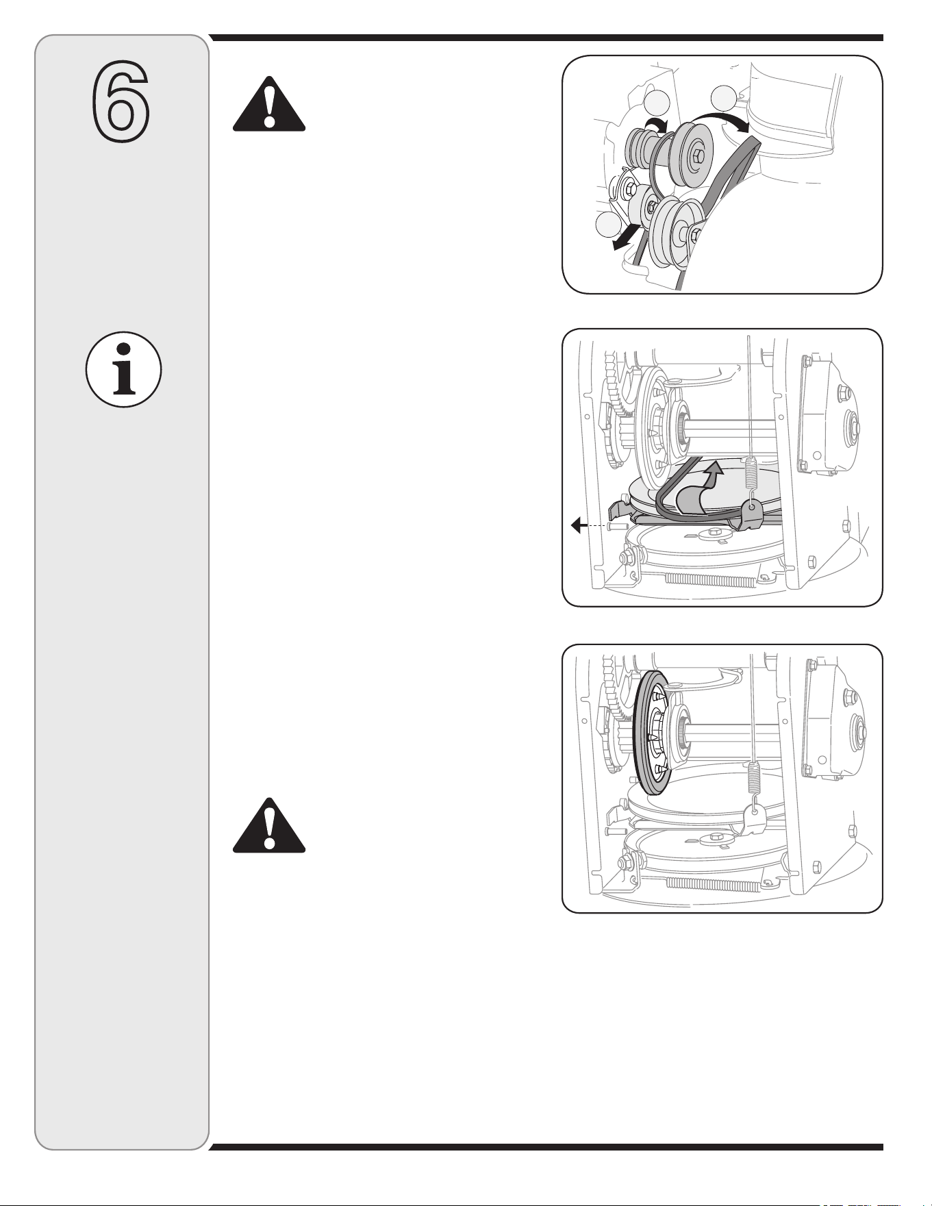
4. a. Roll the auger belt off the engine pulley.
b. Use a wrench to pivot the idler pulley toward the
right. See Figure 6-9.
c. Lift the drive belt off engine pulley.
5. Back out the stop screw until the support bracket
rests on the auger pulley. See Figure 6-10.
6. Slip the drive belt off the pulley and between friction
wheel and drive plate. See Figure 6-10.
7. Remove and replace belt in the reverse order.
NOTE: Repeat the drive control adjustment in the
“Adjustment” section before operating the snowthrower.
Friction Wheel Inspection
If the snow thrower fails to drive with the drive control
engaged, and performing the drive control cable adjust-
ment fails to correct the problem, the friction wheel may
need to be replaced.
NOTE: Special tools are required and several com-
ponents must be removed and in order to replace the
snow thrower’s friction wheel rubber. See an authorized
Service Dealer to have the friction wheel rubber
replaced or phone Customer Support as instructed on
page 2 for information on ordering a Service Manual.
WARNING: Run the engine com-
pletely dry of gasoline before tipping
snowthrower.
To inspect the friction wheel, proceed as follows:
1. Carefully pivot the snow thrower up and forward so
that it rests on the auger housing. See Figure 6-5.
2. Remove the frame cover from the underside of the
snow thrower by removing four self-tapping screws
which secure it. See Figure 6-5.
3. Examine the friction wheel for signs of wear or
cracking. See Figure 6-11.
Off-Season Storage
If unit is to be stored over 30 days, prepare for storage
as instructed in the separate engine manual packed with
your snow thrower.
6
Maintaining
Your Snow
Thrower
NEVER replace the
auger shear pins with
standard hex pins.
Any damage to the
auger gearbox or
other components
as a result of failing
to do so will NOT be
covered by your snow
thrower’s warranty.
Figure 6-9
Figure 6-10
Figure 6-11
Clean snow thrower thoroughly.•
Lubricate as instructed in the Maintenance section of •
this manual.
Refer to engine manual for correct engine storage •
instructions.
Store the snow thrower in a clean, dry area.•
When storing any type of power equipment in a •
poorly ventilated or metal storage shed, care should
be taken to rustproof the equipment, especially
springs, cables and all moving parts.
c
a
b
Loading ...
Loading ...
Loading ...