Loading ...
Loading ...
Loading ...
24
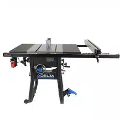
Figure 31
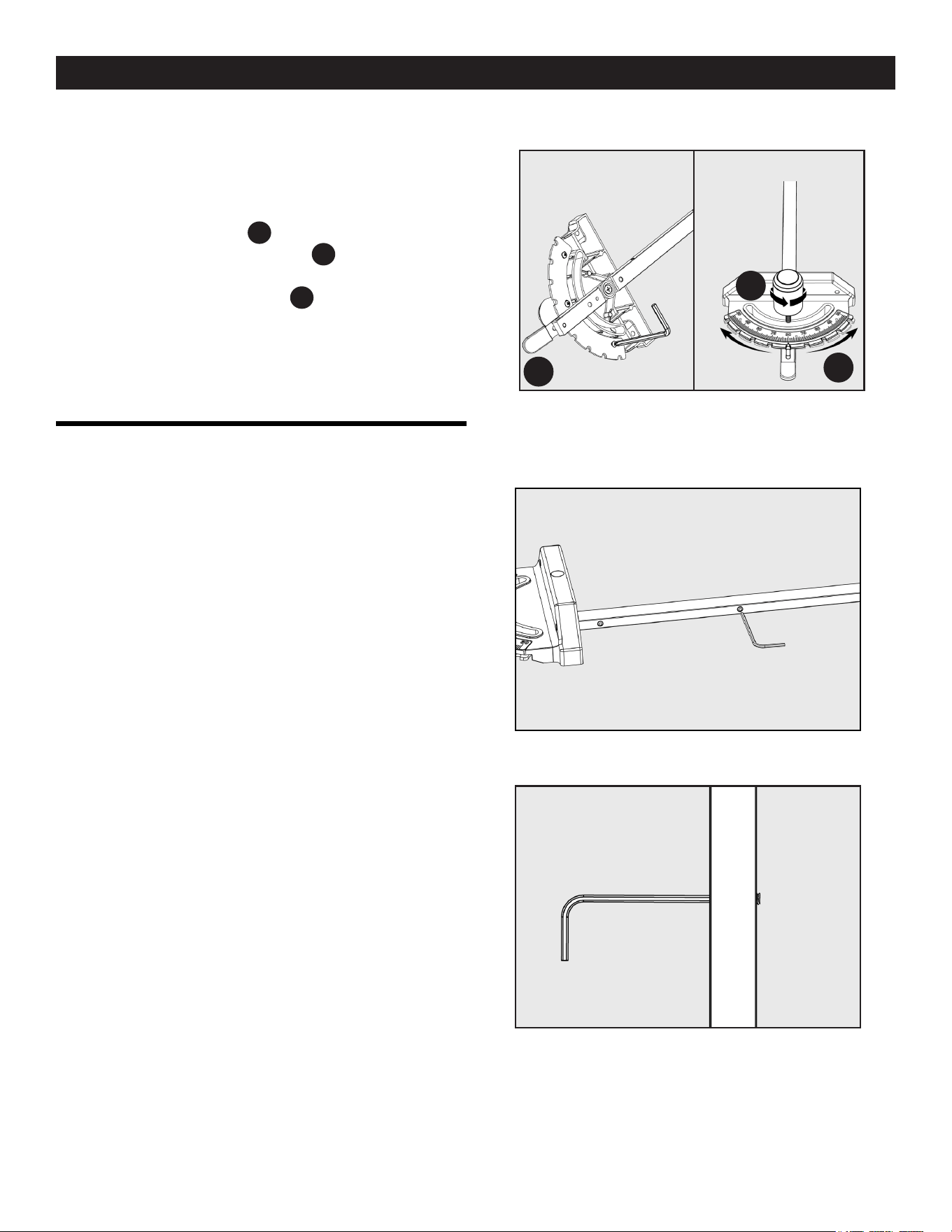
Figure 32
Figure 33
A
B
C
ADJUSTING THE MITER GAUGE
FITMENT
To adjust the tment between the miter gauge bar and the miter
slot:
1. Use a 3/32 inch Allen wrench on any of the three set
screws located on the side of the bar. See Figure 32 and
33.
2. To remove any side-to-side movement between the miter
gauge bar and miter gauge table slot adjust the three small
set screws found along the length of the miter gauge bar.
NOTE: The set screws should extend just beyond the side of the
bar.
ADJUSTING THE MITER GAUGE
SCALE
1. Use the supplied 3/16 inch two-way Allen wrench to loosen
the three Phillip screws located in the back of the miter
gauge, see in Figure 31
A
.
2. Loosen the knob, see in Figure 31
B
.
3. Adjust the detent plate so that the indicator measures the
correct angle, see in Figure 31
C
.
4. Once lined up, re-tighten the knob, and Phillip screws back
in place.
NOTE: Use a combination square to check bar to head angle. If
miter gauge bar is not square to miter gauge head, then adjustment
is necessary.
MAKING ADJUSTMENTS
Loading ...
Loading ...
Loading ...