Loading ...
Loading ...
Loading ...
20
BLADE GUARD
To reduce the risk of serious personal
injury, the Blade Guard MUST be in place when making a
through cut.
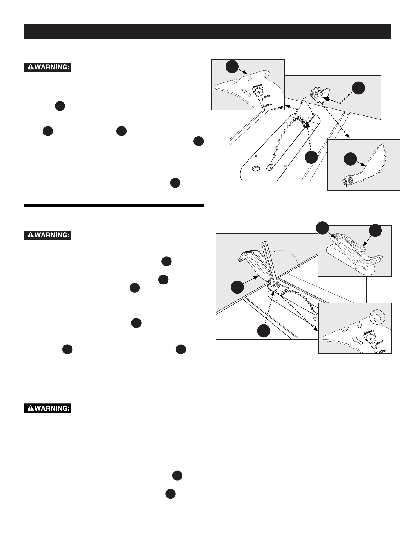
1. Before installing the Blade Guard Assembly
PC5
, make sure
the riving knife is raised to the through-cut position.
2. While holding the Blade Guard Assembly
PC5
in a vertical
position, hook the Locating Pin
B
at the back end of the
Blade Guard Assembly into the slot at the back edge of the
Riving Knife.
3. Rotate the Blade Guard Assembly toward the front of the
Saw until the metal portion
C
of the Blade Guard
Assembly is parallel to the Table as shown in Figure 23.
4. While holding down on the front of the metal portion of the
Guard
C
press the Blade Guard Lock Lever
D
down
until it snaps into the locked position. Check to make sure
the Guard is locked onto the Riving Knife by pulling on the
Guard. If the Guard is not locked, the Blade Guard Lock
Lever will ip up to the unlocked position.
If the metal portion of the Blade Guard
Assembly is not parallel to the table, the Riving Knife is not
in the raised position. Remove Blade Guard Assembly and
Anti-Kickback Pawls and raise Riving Knife, then reinstall
the Anti-Kickback Pawls and the Blade Guard Assembly.
NOTE: Also reference Figure 40, page 28.
To remove the blade guard assembly:
1. Lift the Blade Guard Assembly Lock Lever
D
to the
unlocked position.
2. Rotate the Guard back and slide the Pin
B
from the
Riving Knife Slot.
Figure 23
NOTE: Check the Blade Guard for clearances and free movement.
Figure 22
ANTI-KICKBACK PAWLS
To reduce the risk of serious personal
injury, Anti-Kickback Pawls MUST be in place when making
a through cut.
1. See Figure 22 and locate the Anti-Kickback Pawls Mounting
Slot
A
in the middle of the top edge of the Riving Knife.
2. Slide Slot in the middle of the Anti-Kickback Pawls
Assembly along the top of the Riving Knife until the stem
B
locates the center slot
A
on the Riving Knife.
3. Depress the stem on the Anti-Kickback Pawls Assembly
PC11
to allow the Assembly to drop into the slot. Push down on
the Anti-Kickback Pawls Assembly until it snaps into place
and locks. Release stem. NOTE: Pull up on the Anti-
Kickback Pawls to make sure it is locked in place.
To remove the Anti-Kickback Pawls, depress the stem
B
and pull
the Anti-Kickback Assembly o the Riving Knife.
PC5
A
PC11
A
B
B
ASSEMBLY
C
D
Loading ...
Loading ...
Loading ...