Loading ...
Loading ...
Loading ...
16
ASSEMBLY
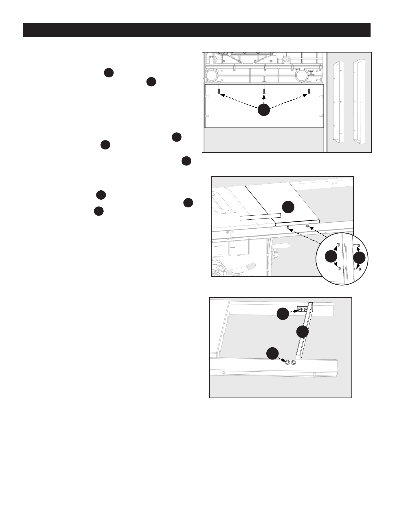
1. Attach the Extension Wings
PC10
to the Table using (6) 5/16-18
x 7/8 Hex Screw with Split Lock Washers
HP7
, (3) for each
Wing. The Wings attach from underneath as shown in Figure
10. Be sure to use a Level or Combination Square to keep the
Extension Wings level with the Table. NOTE: Hole patterns on
the two long edges of the extensions are dierent. See Figure
10A.
2. Attach the Extension Wings to the Front and Rear rails using
(8) 5/16-18 x 1-1/8 inch Flat Countersunk Hex Screw
HP15
and
5/16-18 Hex Flange Nuts
HP13
, (4) for each wing. See Figure
11. Be sure to conrm the Front and Rear Rails are level with
the Extension Wings by using the Rail Alignment Gauge
HP20
.
See Figure 5-9.
3. Repeat this process on Front and Rear Rails for both Extension
Wings.
4. Attach the Spreader Bar
PC17
to the outboard end of the Front
and Rear Rails using (4) M8 x 16 Hex Shoulder Screws
HP8
and (4) M8 Nylock Nuts
HP9
. See Figure 12.
Figure 12
Figure 10
Figure 10A
Figure 11
EXTENSIONEXTENSION
WINGWING
UNDERSIDE OF WINGUNDERSIDE OF WING
EXTENSION WINGS
Hardware Bag “C,D”
HP7
HP15
HP13
PC10
HP8
HP9
PC17
Loading ...
Loading ...
Loading ...