
Loading ...
Loading ...
Loading ...
14
ASSEMBLY
• DO NOT lift Saw without help. Hold it close to your body
while lifting. KEEP knees bent and lift with your legs, not your
back.
• Fully assemble Saw with Leg assembly prior to use. Leg
assembly is an integral and necessary part of the Support
Structure for this Saw.
• DO NOT modify Saw, or create accessories not recommended
for use with this Saw.
• Make sure Power Switch is in “OFF” position before connecting
to Power Supply.
• DO NOT connect to Power Supply until assembly is complete.
STAND
Hardware Bag “A”
Avoid contact with Blade Teeth. KEEP
Blade stored or lowered when possible.
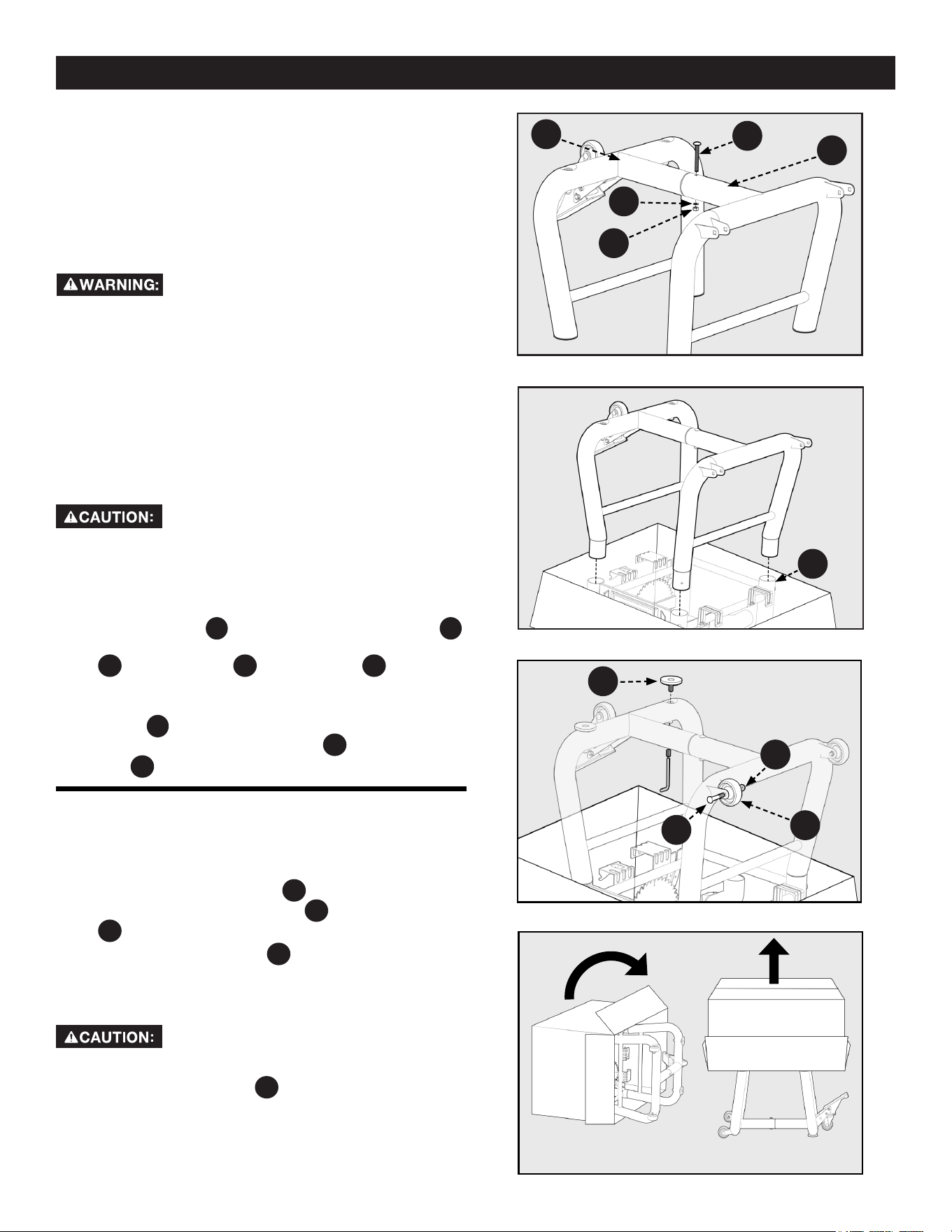
1. Connect the two Tube Legs together by inserting the end
of the Left Leg
PC2
into the end of the Right Leg
PC3
.
Secure them together with (4) M8 x 75mm Carriage Bolt
HP4
, M8 Flat Washer
HP3
, M8 Nylock Nut
HP2
and tighten.
See Figure 1.
2. Insert the four open ends of the Tube Legs into the Leg
Collars
A
as shown. Secure each Leg to the Saw Body
with (4) M6 x 72mm Carriage Bolts
HP4
and (4) M6 Nylock
Nuts
HP5
and tighten. See Figure 2.
TOOLS REQUIRED FOR ASSEMBLY (NOT
INCLUDED):
• Flat Head Screwdriver
• Phillips Head Screwdriver
• 8mm Wrench
• 10mm Wrench
• 12mm Open-Ended Wrench
• 13mm Wrench
Figure
1
• 9/16 inch Wrench
• 5/32 inch Allen Wrench
• Framing (Carpenter's) Square
• Combination Square
• Straight Edge
Figure 2
Figure 3
Figure 4
FIXED WHEELS AND STATIONARY
FEET
Hardware Bag “B”
1. Attach the two Fixed Wheels
PC13
to the Left Leg using the
(2) M8 x 53mm Carriage Bolts
HP6
and M8 Nylock Nuts
HP2
. One for each wheel as shown in Figure 3.
2. Screw the Adjustable Feet
PC12
into the threaded inserts in
the Right Leg.
3. Carefully stand the box right side up and remove packaging
once the machine has been lifted from the ground.
The machine is heavy, two people may
be required to stand the machine up.
4. The two Adjustable Feet
PC12
can be raised and lowered by
rotating them clockwise or counterclockwise. The Feet
may be adjusted to level the Saw and can be locked in
place with the pre-assembled Set Screws using the
provided 6mm Allen Wrench. See Figure 3.
PC3
HP1
HP3
HP2
HP2
PC2
A
PC13
HP6
PC12
Loading ...
Loading ...
Loading ...