Loading ...
Loading ...
Loading ...
21
RIP FENCE
Before installing the Rip Fence, make sure you have attached the
Rip Fence Handle to the Fence Cam. The Rip Fence slides onto the
Rear Fence Rail so that the Hook is under the Rear Rail and rides
on the Front Guide Tube. The Fence locks in place by applying
pressure in a downward motion on the Rip Fence Handle. Rip Fence
alignment should be checked prior to using your saw. To check
alignment of the Rip Fence, see alignment instructions on page 25.
MITER GAUGE
Insert Miter Gauge into each Miter Slot to make sure it slides
freely. See "ADJUSTING THE MITER SCALE" section on page 24 for
adjustment of Miter Gauge Accuracy.
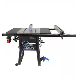
ON-BOARD STORAGE
The DELTA
®
#36-725 T2 Contractor Table Saw comes with On-
Board Storage for the provided Miter Gauge, Blade Wrench, Push
Stick, Fence, Anti-Kickback Pawls and Blade Guard. There is also
On-Board Storage for spare Saw Blades (sold separately). The
Push Stick, Spare Blade (Blade should be stored protected to
avoid injury), Blade Wrench, Anti-Kickback Pawls and Blade Guard
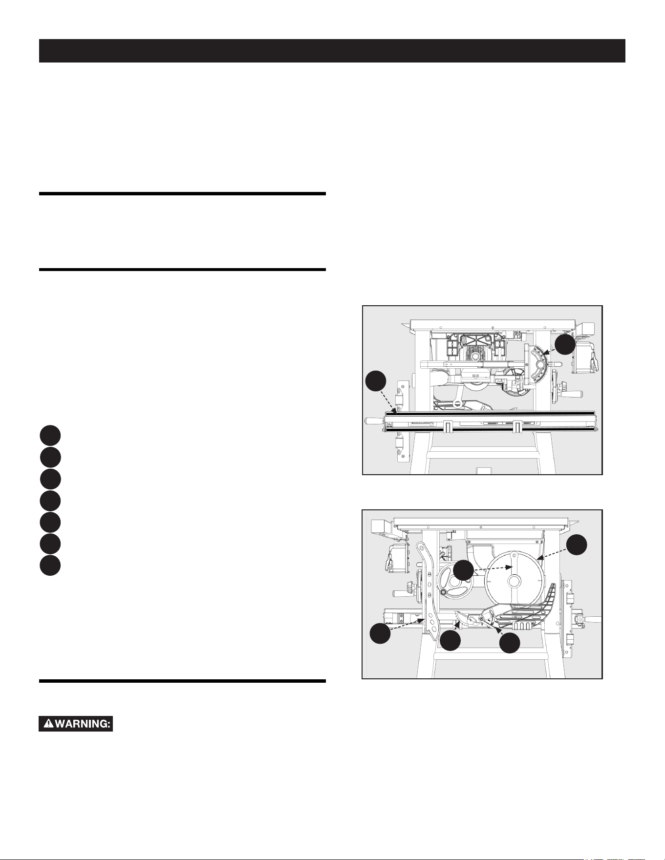
Storage areas are located on the Right Side of the Machine, see
Figure 25. On-board storage for the Miter Gauge and Fence are
located on the left side of the machine as seen in Figure 24.
Figure 24
Figure 25
PC4
PC4
PC5
PC5
PC6
PC6
PC7
PC7
PC9
PC9
PC11
PC16
PC16
PC11
Rip Fence
Blade Guard
Miter Gauge
Push Stick
Blade Wrench
Anti-Kickback Pawls
10 inch Blade (Pre-Installed)
ASSEMBLY
SECURING SAW TO FLOOR
This Saw is designed for mobility. DO NOT
attempt to use the Saw to cut a large or cumbersome workpiece
without rst taking appropriate steps to protect against tipping the
Saw. Examples of appropriate steps include the use of Support
Tables and/or securing the Saw Legs to the oor by replacing the
Saw Feet with Connecting Bolts or by attaching the Legs to a Floor
Mounted Bracket with U-Bolts.
LEFT SIDELEFT SIDE
RIGHT SIDERIGHT SIDE
Loading ...
Loading ...
Loading ...