Loading ...
Loading ...
Loading ...
PC20
HP18
HP19
HP18
17
ASSEMBLY
FENCE GUIDE AND
POWER CONTROL BOX
Hardware Bag “E”
LEFT FENCE LEFT FENCE
GUIDE (SHORT) GUIDE (SHORT)
CONTROL BOXCONTROL BOX
STRAIGHT EDGESTRAIGHT EDGE
BACK BACK
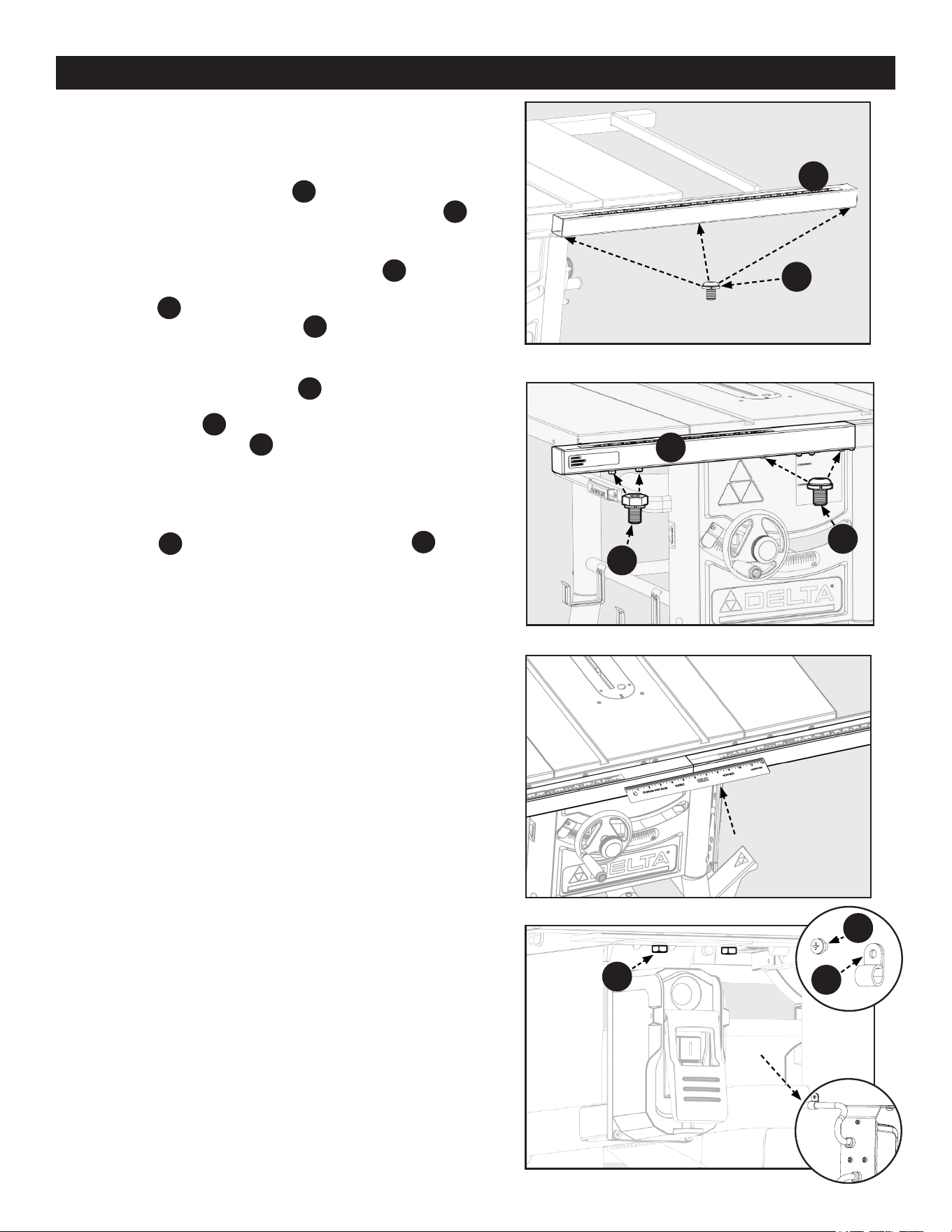
1. Attach the Right Fence Guide
PC20
using (3) 1/4-20 x 1/2
inch Button Head Hex Screw with Split Lock Washers
HP18
through the holes on the bottom side of the Front Rail. See
Figure 13.
2. Attach the Left Fence Guide to the Front Rail
PC20
using (2)
1/4-20 x 1/2 inch Button Head Hex Screw with Split Lock
Washers
HP18
through the right two holes on the bottom
side of the left half Front Rail
PC19
. NOTE: Leave these
screws loose until the control box screws are started.
3. Align the two holes in the Switch Box Bracket with the
holes underneath the Front Rail
PC19
, see Figure 14, located
on the left side of the saw. Secure the Power Control Box
to the Front Rail
PC19
using (2) 1/4-20 x 1/2 inch Hex Screw
with Split Lock Washers
HP19
. Use a ruler to check that both
Left and Right Fence Guides are parallel. See Figure 15.
NOTE: To tighten the bolts that fasten the switch, you may need
to use a 12mm open-ended wrench.
4. Fix the hanging Power Cord at rear side of Front Rail by
Wire Clip
HP17
and M5 x 6mm Phillips Head Screw
HP16
. See
Figure 16.
Figure 13
Figure 14
Figure 15
RIGHT FENCE
GUIDE (LONG)
Figure 16
PC20
HP16
HP17
HP19
Loading ...
Loading ...
Loading ...