Loading ...
Loading ...
Loading ...

12
6. KVM Operation
Computers connected to the KVM switch can be accessed via the local console or over IP. This chapter discusses the basic operation of the KVM
switch, both locally and remotely.
6.1 Sharing USB Peripheral Devices
6.2 Powering Off and Restarting
6.3 Local Console Login
The USB 1.1 port on the LCD panel of the console KVM switch can be used to share USB peripherals between connected computers. Simply
connect a USB device to this port, and any connected computer you switch to will have access to the device. The USB peripheral sharing
functionality works the same whether you are accessing the connected computers via the local console or over IP.
Note: The following limitations apply to the USB peripheral port:
1. This port serves as a 1 port USB 1.1 hub; USB 2.0 devices can be connected, but will not function as designed.
2. USB peripherals can only be shared among computers that are connected to the KVM switch via the USB connectors on the P778-Series
USB/PS2 Combo KVM Cable Kit.
3. USB peripherals can only be shared among computers that are connected to the KVM switch that the USB peripheral is plugged into. If a
USB peripheral is plugged into the USB 1.1 port of the third KVM switch in a daisy-chain installation, only computers connected to that KVM
can access the USB peripheral; computers connected to any other KVM in the installation will not be able to access the USB peripheral.
4. When accessing a USB peripheral on a connected computer, it is recommended that you properly eject the device before switching to another
computer. When switching computers, the device is automatically disconnected from the previous computer and connected to the next, as if it
was manually unplugged from a USB port on one computer and then plugged into the USB port of another computer.
If it becomes necessary to power off the KVM switch, follow this procedure:
1. Shut down all computers connected to the KVM switch. If you are powering off multiple computers in a daisy-chain installation, shut down all
computers connected to each KVM switch you are powering off.
Note: It is necessary to unplug any computers that have the Keyboard Power On function. If left on, the KVM switch will continue to receive
power via these computers.
2. Turn off the KVM switch (console KVM only) and unplug the KVM switch from its power source. Power OFF and unplug each additional KVM
switch in succession.
3. Wait 10 seconds and then plug the KVM switch, starting with the first station, back into its power source. Turn on the power to the KVM
switch (console KVM only).
4. Once the first station KVM switch has ascertained its position in the daisy-chain, power on and plug in the next KVM switch in the installation.
Follow this procedure for each additional KVM switch in the installation.
5. Once all KVM switches in the installation have been powered back ON, turn on the power to all connected computers.
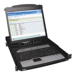
When accessing the console KVM switch for the first time, a prompt
will appear asking for a username and password. The default
username is administrator, and the default password is password.
For security purposes, a “Change Password” prompt will appear
requiring you to immediately change the password from the default. It
is strongly recommended that you also change the default username
to a unique one as well (see section 5.7.4 Changing the Super
Administrator Login for details). Once the KVM has been set up and
user accounts have been created, the login prompt will only appear
when a user logs out of the KVM. When you have entered your
username and password, the OSD will appear with the following page
displayed.
Note: When using the [Scroll Lock, Scroll Lock] OSD invocation
sequence, you must hold down the [Fn] key, as the [Scroll Lock] key
is part of the [Num Lock] key.
Note: 1) The diagram depicts the Administrator’s Main Screen. The User Main Screen does not have the F4 and F6 functions, since they can’t
be accessed by ordinary Users and are reserved for the Administrator.
2) OSD always starts in List view, with the highlight bar at the same position it was when the OSD was last closed.
3) Only the ports that have been set accessible by the Administrator for the currently logged in User are visible.
4) If the port list is collapsed into stations, simply click on the plus sign next to the desired station number, or highlight the desired station
number and hit the [Enter] key.
Loading ...
Loading ...
Loading ...