
PowerFlex 750-Series Drives with TotalFORCE Control
Built-in EtherNet/IP Adapter
Catalog Numbers 20G; 20J
User Manual
Original Instructions
Important User Information
Read this document and the documents listed in the additional resources section about installation, configuration, and
operation of this equipment before you install, configure, operate, or maintain this product. Users are required to
familiarize themselves with installation and wiring instructions in addition to requirements of all applicable codes, laws,
and standards.
Activities including installation, adjustments, putting into service, use, assembly, disassembly, and maintenance are
required to be carried out by suitably trained personnel in accordance with applicable code of practice.
If this equipment is used in a manner not specified by the manufacturer, the protection provided by the equipment may
be impaired.
In no event will Rockwell Automation, Inc. be responsible or liable for indirect or consequential damages resulting from
the use or application of this equipment.
The examples and diagrams in this manual are included solely for illustrative purposes. Because of the many variables and
requirements associated with any particular installation, Rockwell Automation, Inc. cannot assume responsibility or
liability for actual use based on the examples and diagrams.
No patent liability is assumed by Rockwell Automation, Inc. with respect to use of information, circuits, equipment, or
software described in this manual.
Reproduction of the contents of this manual, in whole or in part, without written permission of Rockwell Automation,
Inc., is prohibited.
Throughout this manual, when necessary, we use notes to make you aware of safety considerations.
Labels may also be on or inside the equipment to provide specific precautions.
WARNING: Identifies information about practices or circumstances that can cause an explosion in a hazardous
environment, which may lead to personal injury or death, property damage, or economic loss.
ATTENTION: Identifies information about practices or circumstances that can lead to personal injury or death, property
damage, or economic loss. Attentions help you identify a hazard, avoid a hazard, and recognize the consequence.
IMPORTANT Identifies information that is critical for successful application and understanding of the product.
SHOCK HAZARD: Labels may be on or inside the equipment, for example, a drive or motor, to alert people that dangerous
voltage may be present.
BURN HAZARD: Labels may be on or inside the equipment, for example, a drive or motor, to alert people that surfaces may
reach dangerous temperatures.
ARC FLASH HAZARD: Labels may be on or inside the equipment, for example, a motor control center, to alert people to
potential Arc Flash. Arc Flash will cause severe injury or death. Wear proper Personal Protective Equipment (PPE). Follow ALL
Regulatory requirements for safe work practices and for Personal Protective Equipment (PPE).

Rockwell Automation Publication 750COM-UM009A-EN-P - May 2017 3
Table of Contents
Preface . . . . . . . . . . . . . . . . . . . . . . . . . . . . . . . . . . . . . . . . . . . . . . . . . . . . . . .13
Conventions Used in This Manual . . . . . . . . . . . . . . . . . . . . . . . . . . . . . 13
Additional Resources . . . . . . . . . . . . . . . . . . . . . . . . . . . . . . . . . . . . . . . . . . 13
Chapter 1
Getting Started Components. . . . . . . . . . . . . . . . . . . . . . . . . . . . . . . . . . . . . . . . . . . . . . . . . . 18
Features . . . . . . . . . . . . . . . . . . . . . . . . . . . . . . . . . . . . . . . . . . . . . . . . . . . . . . 18
Dual Ethernet Ports . . . . . . . . . . . . . . . . . . . . . . . . . . . . . . . . . . . . . . . 19
Required Equipment . . . . . . . . . . . . . . . . . . . . . . . . . . . . . . . . . . . . . . . . . . 20
Equipment Shipped with the Drive . . . . . . . . . . . . . . . . . . . . . . . . . 20
User-supplied Equipment . . . . . . . . . . . . . . . . . . . . . . . . . . . . . . . . . . 21
Choose an Ethernet Switch. . . . . . . . . . . . . . . . . . . . . . . . . . . . . . . . . 22
Safety Precautions . . . . . . . . . . . . . . . . . . . . . . . . . . . . . . . . . . . . . . . . . . . . . 23
Chapter 2
Configure the Interface Configuration Tools. . . . . . . . . . . . . . . . . . . . . . . . . . . . . . . . . . . . . . . . . . . 26
Setting the IP Address . . . . . . . . . . . . . . . . . . . . . . . . . . . . . . . . . . . . . . . . . 26
Connecting the Interface to the Network . . . . . . . . . . . . . . . . . . . . . . . 29
Apply Power . . . . . . . . . . . . . . . . . . . . . . . . . . . . . . . . . . . . . . . . . . . . . . . . . . 30
Start-up Status Indications . . . . . . . . . . . . . . . . . . . . . . . . . . . . . . . . . 31
Configuring and Verifying Key Drive Parameters. . . . . . . . . . . . . 33
Use Interface Parameters to Set the IP Address . . . . . . . . . . . . . . . . . . 33
Using the PowerFlex 20-HIM-A6 or 20-HIM-C6S
to Access Parameters. . . . . . . . . . . . . . . . . . . . . . . . . . . . . . . . . . . . . . . 34
Using a BOOTP or DHCP Server. . . . . . . . . . . . . . . . . . . . . . . . . . . . . . 36
Setting the Data Rate . . . . . . . . . . . . . . . . . . . . . . . . . . . . . . . . . . . . . . . . . . 40
Setting Communication Hierarchy . . . . . . . . . . . . . . . . . . . . . . . . . . . . . 41
Setting a Controller Hierarchy. . . . . . . . . . . . . . . . . . . . . . . . . . . . . . 41
Setting a Fault Action . . . . . . . . . . . . . . . . . . . . . . . . . . . . . . . . . . . . . . . . . 44
Changing the Fault Action . . . . . . . . . . . . . . . . . . . . . . . . . . . . . . . . . 44
Setting the Fault Configuration Parameters. . . . . . . . . . . . . . . . . . 45
Resetting the Interface . . . . . . . . . . . . . . . . . . . . . . . . . . . . . . . . . . . . . . . . . 45
Restore Interface Parameters to Default Configurations . . . . . . . . . . 45
Viewing the Interface Status Using Parameters. . . . . . . . . . . . . . . . . . . 47
Updating the Interface Firmware . . . . . . . . . . . . . . . . . . . . . . . . . . . . . . . 47
Chapter 3
Configuring the Drive in a Logix
System
Establish Communication . . . . . . . . . . . . . . . . . . . . . . . . . . . . . . . . . . . . . 50
Uploading the Electronic Data Sheet (EDS) File . . . . . . . . . . . . . . . . . 52
Obtain Add-on Profiles. . . . . . . . . . . . . . . . . . . . . . . . . . . . . . . . . . . . . . . . 53
Create Logix Controller Project . . . . . . . . . . . . . . . . . . . . . . . . . . . . . . . . 53
Example Network . . . . . . . . . . . . . . . . . . . . . . . . . . . . . . . . . . . . . . . . . 53
Adding the Bridge to the I/O Configuration. . . . . . . . . . . . . . . . . 54
Add the Drive to the Project . . . . . . . . . . . . . . . . . . . . . . . . . . . . . . . . . . . 56

4 Rockwell Automation Publication 750COM-UM009A-EN-P - May 2017
Table of Contents
Configure Input and Output Data . . . . . . . . . . . . . . . . . . . . . . . . . . 59
Download the Configuration to the Controller . . . . . . . . . . . . . . . . . . 62
Correlate the Drive with the Controller . . . . . . . . . . . . . . . . . . . . . 64
Updating the AOPs and Database Files . . . . . . . . . . . . . . . . . . . . . . . . . 65
Configuration to Aid in Field-Failure Replacement . . . . . . . . . . . . . . 67
Using an Ethernet Switch with DHCP/BOOTP Server . . . . . . . . . . 68
Using Firmware Supervisor. . . . . . . . . . . . . . . . . . . . . . . . . . . . . . . . . 69
Using Automatic Device Configuration (ADC) . . . . . . . . . . . . . . . . . 71
Configure a PowerFlex 755T Drive for ADC . . . . . . . . . . . . . . . . 73
ADC and Logix Memory. . . . . . . . . . . . . . . . . . . . . . . . . . . . . . . . . . . 76
Peripheral Changes When Using ADC. . . . . . . . . . . . . . . . . . . . . . 76
Special Considerations For 20-750-S1 Safe Speed Module (S1) 77
Special Considerations for Communications and Option
Developers Kit Option Cards. . . . . . . . . . . . . . . . . . . . . . . . . . . . . . . 79
Testing ADC . . . . . . . . . . . . . . . . . . . . . . . . . . . . . . . . . . . . . . . . . . . . . 79
Monitoring ADC Progress . . . . . . . . . . . . . . . . . . . . . . . . . . . . . . . . . 80
Programmatically Monitoring Connection Status and the ADC
Configuration Signature . . . . . . . . . . . . . . . . . . . . . . . . . . . . . . . . . . . . . . . 83
Best Practices. . . . . . . . . . . . . . . . . . . . . . . . . . . . . . . . . . . . . . . . . . . . . . 85
Chapter 4
Using the I/O About I/O Messaging . . . . . . . . . . . . . . . . . . . . . . . . . . . . . . . . . . . . . . . . . 87
Understanding the ControlLogix Controller I/O Image. . . . . . . . . . 88
Using Logic Command/Status . . . . . . . . . . . . . . . . . . . . . . . . . . . . . . . . . 89
Using Reference/Feedback . . . . . . . . . . . . . . . . . . . . . . . . . . . . . . . . . . . . . 89
Using Datalinks . . . . . . . . . . . . . . . . . . . . . . . . . . . . . . . . . . . . . . . . . . . . . . . 91
Example of Ladder Logic Program Information . . . . . . . . . . . . . . . . . . 92
Functions of the Example Programs . . . . . . . . . . . . . . . . . . . . . . . . . 92
Logic Command/Status Words. . . . . . . . . . . . . . . . . . . . . . . . . . . . . 92
ControlLogix Controller Example . . . . . . . . . . . . . . . . . . . . . . . . . . . . . . 92
Create Ladder Logic Using the RSLogix or
Studio 5000 with Drive Add-on Profiles. . . . . . . . . . . . . . . . . . . . . 92
Chapter 5
Using Explicit Messaging About Explicit Messaging . . . . . . . . . . . . . . . . . . . . . . . . . . . . . . . . . . . . . . 96
Performing Explicit Messaging . . . . . . . . . . . . . . . . . . . . . . . . . . . . . . . . . 98
ControlLogix Controller Examples . . . . . . . . . . . . . . . . . . . . . . . . . . . . . 99
Ladder Logic Program to Read a Single Parameter . . . . . . . . . . . . 99
Formatting a Message to Read a Single Parameter . . . . . . . . . . . 100
Ladder Logic Program to Write a Single Parameter . . . . . . . . . . 101
Formatting a Message to Write a Single Parameter . . . . . . . . . . 102
Ladder Logic Program to Read Multiple Parameters . . . . . . . . . 103
Formatting a Message to Read Multiple Parameters. . . . . . . . . . 104
Ladder Logic Program to Write Multiple Parameters . . . . . . . . 106
Formatting a Message to Write Multiple Parameters. . . . . . . . . 107

Rockwell Automation Publication 750COM-UM009A-EN-P - May 2017 5
Table of Contents
Explanation of Request and Response Data for
Scattered Read Multiple Messaging . . . . . . . . . . . . . . . . . . . . . . . . 109
Chapter 6
Troubleshooting Viewing Interface Diagnostic Items . . . . . . . . . . . . . . . . . . . . . . . . . . . . 113
Viewing and Clearing Events . . . . . . . . . . . . . . . . . . . . . . . . . . . . . . . . . . 116
Drive Status Indicators . . . . . . . . . . . . . . . . . . . . . . . . . . . . . . . . . . . . . . . 118
ENET Status Indicator . . . . . . . . . . . . . . . . . . . . . . . . . . . . . . . . . . . . . . . 119
LNK1 Status Indicator . . . . . . . . . . . . . . . . . . . . . . . . . . . . . . . . . . . . . . . 119
LNK2 Status Indicator . . . . . . . . . . . . . . . . . . . . . . . . . . . . . . . . . . . . . . . 120
Appendix A
Status Indicators Understanding the Status Indicators . . . . . . . . . . . . . . . . . . . . . . . . . . . 121
ENET Status Indicator . . . . . . . . . . . . . . . . . . . . . . . . . . . . . . . . . . . . . . . 122
LINK Status Indicators . . . . . . . . . . . . . . . . . . . . . . . . . . . . . . . . . . . . . . . 123
Appendix B
Specifications Communication . . . . . . . . . . . . . . . . . . . . . . . . . . . . . . . . . . . . . . . . . . . . . 125
Regulatory Compliance. . . . . . . . . . . . . . . . . . . . . . . . . . . . . . . . . . . . . . . 125
Appendix C
Interface Parameters How Parameters Are Organized . . . . . . . . . . . . . . . . . . . . . . . . . . . . . . . 127
Parameter List . . . . . . . . . . . . . . . . . . . . . . . . . . . . . . . . . . . . . . . . . . . . . . . 128
Appendix D
EtherNet/IP Objects Supported Data Types . . . . . . . . . . . . . . . . . . . . . . . . . . . . . . . . . . . . . . . . 135
Identity Object. . . . . . . . . . . . . . . . . . . . . . . . . . . . . . . . . . . . . . . . . . . . . . . 136
Assembly Object . . . . . . . . . . . . . . . . . . . . . . . . . . . . . . . . . . . . . . . . . . . . . 137
PCCC Object . . . . . . . . . . . . . . . . . . . . . . . . . . . . . . . . . . . . . . . . . . . . . . . 138
DPI Device Object . . . . . . . . . . . . . . . . . . . . . . . . . . . . . . . . . . . . . . . . . . . 142
DPI Parameter Object . . . . . . . . . . . . . . . . . . . . . . . . . . . . . . . . . . . . . . . . 145
Formulas for Converting . . . . . . . . . . . . . . . . . . . . . . . . . . . . . . . . . . 152
DPI Fault Object. . . . . . . . . . . . . . . . . . . . . . . . . . . . . . . . . . . . . . . . . . . . . 154
DPI Alarm Object. . . . . . . . . . . . . . . . . . . . . . . . . . . . . . . . . . . . . . . . . . . . 156
DPI Diagnostic Object . . . . . . . . . . . . . . . . . . . . . . . . . . . . . . . . . . . . . . . 158
DPI Time Object . . . . . . . . . . . . . . . . . . . . . . . . . . . . . . . . . . . . . . . . . . . . 159
Host DPI Parameter Object. . . . . . . . . . . . . . . . . . . . . . . . . . . . . . . . . . . 163
Formulas for Converting . . . . . . . . . . . . . . . . . . . . . . . . . . . . . . . . . . 169
TCP/IP Interface Object . . . . . . . . . . . . . . . . . . . . . . . . . . . . . . . . . . . . . 171
Ethernet Link Object. . . . . . . . . . . . . . . . . . . . . . . . . . . . . . . . . . . . . . . . . 173

6 Rockwell Automation Publication 750COM-UM009A-EN-P - May 2017
Table of Contents
Appendix E
Logic Command/Status Words:
PowerFlex 755T Drives and Bus
Supplies
Drive Products. . . . . . . . . . . . . . . . . . . . . . . . . . . . . . . . . . . . . . . . . . . . . . . 175
Logic Command Word . . . . . . . . . . . . . . . . . . . . . . . . . . . . . . . . . . . . . . . 175
Logic Status Word . . . . . . . . . . . . . . . . . . . . . . . . . . . . . . . . . . . . . . . . . . . 176
Bus Supply Products. . . . . . . . . . . . . . . . . . . . . . . . . . . . . . . . . . . . . . . . . . 178
Logic Command Word . . . . . . . . . . . . . . . . . . . . . . . . . . . . . . . . . . . . . . . 178
Logic Status Word . . . . . . . . . . . . . . . . . . . . . . . . . . . . . . . . . . . . . . . . . . . 179
Glossary . . . . . . . . . . . . . . . . . . . . . . . . . . . . . . . . . . . . . . . . . . . . . . . . . . . . 181
Index . . . . . . . . . . . . . . . . . . . . . . . . . . . . . . . . . . . . . . . . . . . . . . . . . . . . . . 189

Rockwell Automation Publication 750COM-UM009A-EN-P - May 2017 7
Table of Contents
Drive and Interface Start-up Status Indications . . . . . . . . . . . . . . . . . . . . . . . . . . . . . . . . . . . . . . . . . 32
Fault Configuration Parameter Values . . . . . . . . . . . . . . . . . . . . . . . . . . . . . . . . . . . . . . . . . . . . . . . 45
Interface Status Parameters . . . . . . . . . . . . . . . . . . . . . . . . . . . . . . . . . . . . . . . . . . . . . . . . . . . . . . . . 47
Drive Status Indicators - Operational . . . . . . . . . . . . . . . . . . . . . . . . . . . . . . . . . . . . . . . . . . . . . . . . 81
Logix Control ADC Failure Examples . . . . . . . . . . . . . . . . . . . . . . . . . . . . . . . . . . . . . . . . . . . . . . . 82
ControlLogix I/O Image for PowerFlex 755T Drives
(32-bit Logic Command/Status, Reference/Feedback, and Datalinks) . . . . . . . . . . . . . . . . . . . . . . . 89
PowerFlex755T Drives Example Velocity Reference/Feedback Scaling . . . . . . . . . . . . . . . . . . . . 90
Explicit Messaging Class Code Compatibility with PowerFlex 755T Drive . . . . . . . . . . . . . . . . . . 96
Explicit Messaging Compatibility with PowerFlex 755T Drive . . . . . . . . . . . . . . . . . . . . . . . . . . . . 97
Example Controller Tags to Read a Single Parameter . . . . . . . . . . . . . . . . . . . . . . . . . . . . . . . . . . . . 99
Example Controller Tags to Write a Single Parameter . . . . . . . . . . . . . . . . . . . . . . . . . . . . . . . . . . . 101
Example Controller Tags to Read Multiple Parameters . . . . . . . . . . . . . . . . . . . . . . . . . . . . . . . . . . 103
Example Controller Tags to Write Multiple Parameters . . . . . . . . . . . . . . . . . . . . . . . . . . . . . . . . . . 106
Data Structures for Scattered Read Messages . . . . . . . . . . . . . . . . . . . . . . . . . . . . . . . . . . . . . . . . . . 109
Data Structures for Scattered Write Messages . . . . . . . . . . . . . . . . . . . . . . . . . . . . . . . . . . . . . . . . . . 110
Interface Diagnostic Items . . . . . . . . . . . . . . . . . . . . . . . . . . . . . . . . . . . . . . . . . . . . . . . . . . . . . . . . . 113
Interface Diagnostic Items . . . . . . . . . . . . . . . . . . . . . . . . . . . . . . . . . . . . . . . . . . . . . . . . . . . . . . . . . 116
PowerFlex 755T Drive Status Indicator Descriptions . . . . . . . . . . . . . . . . . . . . . . . . . . . . . . . . . . . . 118
ENET Status Indicator Description . . . . . . . . . . . . . . . . . . . . . . . . . . . . . . . . . . . . . . . . . . . . . . . . . . 119
LNK1 Status Indicator Descriptions . . . . . . . . . . . . . . . . . . . . . . . . . . . . . . . . . . . . . . . . . . . . . . . . . 119
LNK2 Status Indicator Descriptions . . . . . . . . . . . . . . . . . . . . . . . . . . . . . . . . . . . . . . . . . . . . . . . . . 120
ENET Status Indicators . . . . . . . . . . . . . . . . . . . . . . . . . . . . . . . . . . . . . . . . . . . . . . . . . . . . . . . . . . . 122
LNK1 Status Indicator . . . . . . . . . . . . . . . . . . . . . . . . . . . . . . . . . . . . . . . . . . . . . . . . . . . . . . . . . . . . 123
LNK2 Status Indicator . . . . . . . . . . . . . . . . . . . . . . . . . . . . . . . . . . . . . . . . . . . . . . . . . . . . . . . . . . . . 123
Port 0: Parameter List . . . . . . . . . . . . . . . . . . . . . . . . . . . . . . . . . . . . . . . . . . . . . . . . . . . . . . . . . . . . 128
Supported Data Types . . . . . . . . . . . . . . . . . . . . . . . . . . . . . . . . . . . . . . . . . . . . . . . . . . . . . . . . . . . . 135
Identity Object: Class Code . . . . . . . . . . . . . . . . . . . . . . . . . . . . . . . . . . . . . . . . . . . . . . . . . . . . . . . . 136
Identity Object: Services . . . . . . . . . . . . . . . . . . . . . . . . . . . . . . . . . . . . . . . . . . . . . . . . . . . . . . . . . . 136
Identity Object: Instances . . . . . . . . . . . . . . . . . . . . . . . . . . . . . . . . . . . . . . . . . . . . . . . . . . . . . . . . . 136
Identity Object: Class Attributes . . . . . . . . . . . . . . . . . . . . . . . . . . . . . . . . . . . . . . . . . . . . . . . . . . . . 136
Identity Objects: Instance Attributes . . . . . . . . . . . . . . . . . . . . . . . . . . . . . . . . . . . . . . . . . . . . . . . . . 136
Assembly Object: Class Code . . . . . . . . . . . . . . . . . . . . . . . . . . . . . . . . . . . . . . . . . . . . . . . . . . . . . . 137
Assembly Object: Services . . . . . . . . . . . . . . . . . . . . . . . . . . . . . . . . . . . . . . . . . . . . . . . . . . . . . . . . 137
Assembly Object: Instances . . . . . . . . . . . . . . . . . . . . . . . . . . . . . . . . . . . . . . . . . . . . . . . . . . . . . . . . 137
Assembly Object: Class Attributes . . . . . . . . . . . . . . . . . . . . . . . . . . . . . . . . . . . . . . . . . . . . . . . . . . 137
Assembly Object: Instance Attributes . . . . . . . . . . . . . . . . . . . . . . . . . . . . . . . . . . . . . . . . . . . . . . . . 138
PCCC Object: Class Code . . . . . . . . . . . . . . . . . . . . . . . . . . . . . . . . . . . . . . . . . . . . . . . . . . . . . . . . . 138
PCCC Object: Services . . . . . . . . . . . . . . . . . . . . . . . . . . . . . . . . . . . . . . . . . . . . . . . . . . . . . . . . . . . 138
PCCC Object: Message Structure for Execute_PCCC . . . . . . . . . . . . . . . . . . . . . . . . . . . . . . . . . . . 139
PCCC Object: Message Structure for Execute_DH+ . . . . . . . . . . . . . . . . . . . . . . . . . . . . . . . . . . . . 139
PCCC Object: EtherNet/IP Interface Supports . . . . . . . . . . . . . . . . . . . . . . . . . . . . . . . . . . . . . . . . . 139
N-File Descriptions (All N-files are 16-Bit integers) . . . . . . . . . . . . . . . . . . . . . . . . . . . . . . . . . . . . 140
DPI Device Object: Class Code . . . . . . . . . . . . . . . . . . . . . . . . . . . . . . . . . . . . . . . . . . . . . . . . . . . . . 142
DPI Device Object: Service . . . . . . . . . . . . . . . . . . . . . . . . . . . . . . . . . . . . . . . . . . . . . . . . . . . . . . . . 142
DPI Device Object: Instances . . . . . . . . . . . . . . . . . . . . . . . . . . . . . . . . . . . . . . . . . . . . . . . . . . . . . . 142
DPI Device Object: Nonvolatile Class Attributes . . . . . . . . . . . . . . . . . . . . . . . . . . . . . . . . . . . . . . . 143

8 Rockwell Automation Publication 750COM-UM009A-EN-P - May 2017
Table of Contents
DPI Device Object: Instance Attributes . . . . . . . . . . . . . . . . . . . . . . . . . . . . . . . . . . . . . . . . . . . . . . . 145
DPI Parameter Object: Class Code . . . . . . . . . . . . . . . . . . . . . . . . . . . . . . . . . . . . . . . . . . . . . . . . . . 145
DPI Parameter Object: Instances . . . . . . . . . . . . . . . . . . . . . . . . . . . . . . . . . . . . . . . . . . . . . . . . . . . . 145
DPI Parameter Object: Class Attributes . . . . . . . . . . . . . . . . . . . . . . . . . . . . . . . . . . . . . . . . . . . . . . 146
DPI Parameter Object: Instance Attributes . . . . . . . . . . . . . . . . . . . . . . . . . . . . . . . . . . . . . . . . . . . . 147
DPI Parameter Object: Descriptor Attributes . . . . . . . . . . . . . . . . . . . . . . . . . . . . . . . . . . . . . . . . . . 150
DPI Parameter Object: Extended Descriptor Attributes . . . . . . . . . . . . . . . . . . . . . . . . . . . . . . . . . . 151
DPI Parameter Object: Common Services . . . . . . . . . . . . . . . . . . . . . . . . . . . . . . . . . . . . . . . . . . . . . 153
DPI Parameter Object Specific Services . . . . . . . . . . . . . . . . . . . . . . . . . . . . . . . . . . . . . . . . . . . . . . 153
Get_Attributes_Scattered and Set_Attributes_Scattered . . . . . . . . . . . . . . . . . . . . . . . . . . . . . . . . . . 153
Get_Attributes_Scattered and Set_Attributes_Scattered: Response . . . . . . . . . . . . . . . . . . . . . . . . . 153
DPI Fault Object: Class Code . . . . . . . . . . . . . . . . . . . . . . . . . . . . . . . . . . . . . . . . . . . . . . . . . . . . . . 154
DPI Fault Object: Services . . . . . . . . . . . . . . . . . . . . . . . . . . . . . . . . . . . . . . . . . . . . . . . . . . . . . . . . 154
DPI Fault Object: Instances . . . . . . . . . . . . . . . . . . . . . . . . . . . . . . . . . . . . . . . . . . . . . . . . . . . . . . . . 154
DPI Fault Object: Class Attributes . . . . . . . . . . . . . . . . . . . . . . . . . . . . . . . . . . . . . . . . . . . . . . . . . . 155
DPI Fault Object Instance Attributes . . . . . . . . . . . . . . . . . . . . . . . . . . . . . . . . . . . . . . . . . . . . . . . . . 155
DPI Alarm Object: Class Code . . . . . . . . . . . . . . . . . . . . . . . . . . . . . . . . . . . . . . . . . . . . . . . . . . . . . 156
DPI Alarm Object: Services . . . . . . . . . . . . . . . . . . . . . . . . . . . . . . . . . . . . . . . . . . . . . . . . . . . . . . . 156
DPI Alarm Object: Instances . . . . . . . . . . . . . . . . . . . . . . . . . . . . . . . . . . . . . . . . . . . . . . . . . . . . . . . 156
DPI Alarm Object: Class Attributes . . . . . . . . . . . . . . . . . . . . . . . . . . . . . . . . . . . . . . . . . . . . . . . . . 156
DPI Alarm Objects: Instance Attributes . . . . . . . . . . . . . . . . . . . . . . . . . . . . . . . . . . . . . . . . . . . . . . 157
DPI Diagnostic Object: Class Code . . . . . . . . . . . . . . . . . . . . . . . . . . . . . . . . . . . . . . . . . . . . . . . . . . 158
DPI Diagnostic Object: Services . . . . . . . . . . . . . . . . . . . . . . . . . . . . . . . . . . . . . . . . . . . . . . . . . . . . 158
DPI Diagnostic Object: Instances . . . . . . . . . . . . . . . . . . . . . . . . . . . . . . . . . . . . . . . . . . . . . . . . . . . 158
DPI Diagnostic Object: Class Attributes . . . . . . . . . . . . . . . . . . . . . . . . . . . . . . . . . . . . . . . . . . . . . . 158
DPI Diagnostic Object: Instance Attributes . . . . . . . . . . . . . . . . . . . . . . . . . . . . . . . . . . . . . . . . . . . . 159
DPI Time Object: Class Code . . . . . . . . . . . . . . . . . . . . . . . . . . . . . . . . . . . . . . . . . . . . . . . . . . . . . . 159
DPI Time Object: Services . . . . . . . . . . . . . . . . . . . . . . . . . . . . . . . . . . . . . . . . . . . . . . . . . . . . . . . . 160
DPI Time Object: Instances . . . . . . . . . . . . . . . . . . . . . . . . . . . . . . . . . . . . . . . . . . . . . . . . . . . . . . . . 160
DPI Time Object: Class Attributes . . . . . . . . . . . . . . . . . . . . . . . . . . . . . . . . . . . . . . . . . . . . . . . . . . 160
DPI Time Object: Instance Attributes . . . . . . . . . . . . . . . . . . . . . . . . . . . . . . . . . . . . . . . . . . . . . . . . 161
Host DPI Parameter Object: Class Code . . . . . . . . . . . . . . . . . . . . . . . . . . . . . . . . . . . . . . . . . . . . . . 163
Host DPI Parameter Object: Instances . . . . . . . . . . . . . . . . . . . . . . . . . . . . . . . . . . . . . . . . . . . . . . . . 163
Host DPI Parameter Object: Class Attributes . . . . . . . . . . . . . . . . . . . . . . . . . . . . . . . . . . . . . . . . . . 163
Host DPI Parameter Object: Instance Attributes . . . . . . . . . . . . . . . . . . . . . . . . . . . . . . . . . . . . . . . . 164
Host DPI Parameter Object: Descriptor Attributes . . . . . . . . . . . . . . . . . . . . . . . . . . . . . . . . . . . . . . 167
Host DPI Parameter Object: Extended Descriptor Attributes . . . . . . . . . . . . . . . . . . . . . . . . . . . . . . 168
Host DPI Parameter Object: Common Service . . . . . . . . . . . . . . . . . . . . . . . . . . . . . . . . . . . . . . . . . 169
Host DPI Parameter Object: Object Specific Services . . . . . . . . . . . . . . . . . . . . . . . . . . . . . . . . . . . 170
Get_Attributes_Scattered and Set_Attributes_Scattered . . . . . . . . . . . . . . . . . . . . . . . . . . . . . . . . . . 170
Get_Attributes_Scattered and Set_Attributes_Scattered Response . . . . . . . . . . . . . . . . . . . . . . . . . . 170
TCP/IP Interface Object: Class Code . . . . . . . . . . . . . . . . . . . . . . . . . . . . . . . . . . . . . . . . . . . . . . . . 171
TCP/IP Interface Object: Services . . . . . . . . . . . . . . . . . . . . . . . . . . . . . . . . . . . . . . . . . . . . . . . . . . . 171
TCP/IP Interface Object: Instances . . . . . . . . . . . . . . . . . . . . . . . . . . . . . . . . . . . . . . . . . . . . . . . . . . 171
TCP/IP Interface Object: Class Attributes . . . . . . . . . . . . . . . . . . . . . . . . . . . . . . . . . . . . . . . . . . . . . 171
TCP/IP Interface Object: Instance Attributes . . . . . . . . . . . . . . . . . . . . . . . . . . . . . . . . . . . . . . . . . . 171
Ethernet Link Object: Class Code . . . . . . . . . . . . . . . . . . . . . . . . . . . . . . . . . . . . . . . . . . . . . . . . . . . 173

Rockwell Automation Publication 750COM-UM009A-EN-P - May 2017 9
Table of Contents
Ethernet Link Object: Services . . . . . . . . . . . . . . . . . . . . . . . . . . . . . . . . . . . . . . . . . . . . . . . . . . . . . 173
Ethernet Link Object: Instances . . . . . . . . . . . . . . . . . . . . . . . . . . . . . . . . . . . . . . . . . . . . . . . . . . . . . 173
Ethernet Link Object: Class Attributes . . . . . . . . . . . . . . . . . . . . . . . . . . . . . . . . . . . . . . . . . . . . . . . 173
Ethernet Link Object: Instance Attributes . . . . . . . . . . . . . . . . . . . . . . . . . . . . . . . . . . . . . . . . . . . . . 173
Logic Command Word . . . . . . . . . . . . . . . . . . . . . . . . . . . . . . . . . . . . . . . . . . . . . . . . . . . . . . . . . . . 175
Logic Status Word . . . . . . . . . . . . . . . . . . . . . . . . . . . . . . . . . . . . . . . . . . . . . . . . . . . . . . . . . . . . . . . 176
Logic Command Word . . . . . . . . . . . . . . . . . . . . . . . . . . . . . . . . . . . . . . . . . . . . . . . . . . . . . . . . . . . 178
Logic Status Words . . . . . . . . . . . . . . . . . . . . . . . . . . . . . . . . . . . . . . . . . . . . . . . . . . . . . . . . . . . . . . 179

10 Rockwell Automation Publication 750COM-UM009A-EN-P - May 2017
Table of Contents
Notes:

Rockwell Automation Publication 750COM-UM009A-EN-P - May 2017 13
Preface
This manual provides information about the dual-port, built-in EtherNet/IP
interface in PowerFlex® 755T drives and bus supplies, and how to use it for
network communication.
To order paper copies of documentation, contact your local Allen-Bradley
distributor or Rockwell Automation® sales representative.
To find your local Allen-Bradley distributor or sales representative, visit http://
www.rockwellautomation.com/locations.
For information, such as firmware updates or answers to drive-related
questions, go to the Drives Service and Support website at http://
www.ab.com/support/abdrives and click the Downloads or Knowledgebase
link.
Conventions Used in This
Manual
These conventions are used throughout this manual:
Parameter names are shown in the format Device Parameter xxx - [*] or Host
Parameter xxx - [*]. The xxx represents the parameter number. The *
represents the parameter name—for example, Device Parameter 01 -
[Operating Mode].
• Where a parameter is referenced outside of the native port, it is
referenced as Port#:Parameter# [parameter name]
(0:301 - [Net Addr Scr] or 10:350 - [Vref Source])
• The dialog box images in this manual resulted from using this software:
– RSLinx® Classic software, version 2.52
– RSLogix 5000® software, version 20, for Automatic Device
Configuration (ADC) information
– Studio 5000™ environment, version 21 or later, for Automatic Device
Configuration (ADC) information
Different versions of the software can have dialog boxes that vary in
appearance, and differences in procedures.
Additional Resources
These documents contain additional information concerning related products
from Rockwell Automation.
Resource Description
PowerFlex 750-Series Products with TotalFORCE Control
Installation Instructions, publication 750-IN100
Provides the basic steps to install PowerFlex 755TL
low harmonic drives, PowerFlex 755TR regenerative
drives, and PowerFlex 755TM drive systems.
PowerFlex 755TM IP00 Open Type Kits Installation
Instructions, publication 750-IN101
Provides instructions to install IP00 Open Type kits in
user-supplied enclosures.
14 Rockwell Automation Publication 750COM-UM009A-EN-P - May 2017
Preface
PowerFlex 755TM AC Precharge Modules Unpacking and
Lifting Instructions, publication 750-IN102
These publications provide detailed information on:
• Component weights
• Precautions and recommendations
• Hardware attachment points
• Lifting the component out of the packaging
PowerFlex 755TM DC Precharge Modules Unpacking and
Lifting Instructions, publication 750-IN103
PowerFlex 755TM Power and Filter Modules Unpacking
and Lifting Instructions, publication 750-IN104
PowerFlex 750-Series Service Cart and DCPC Module Lift
Installation Instructions, publication 750-IN105
Provides detailed set-up and operating instructions
for the module service cart and DC precharge module
lift.
PowerFlex 755TM Power and Filter Module Storage
Hardware Instructions, publication 750-IN106
Provides detailed installation and usage instructions
for this hardware accessory.
PowerFlex 755T Module Service Ramp Instructions,
publication 750-IN108
Provides detailed usage instructions for the module
service ramp.
PowerFlex 750-Series Products with TotalFORCE Control
Product Information, publication 750-PC100
These publications identify technical documentation
resources that can be obtained on-line at http://
www.rockwellautomation.com/global/literature-
library/overview.page.
PowerFlex 755TM IP00 Open Type Kits Product
Information, publication 750-PC101
PowerFlex 755TM UL-Listed Accessories Product
Information, publication 750-PC102
PowerFlex 755TM Accessories Product Information,
publication 750-PC103
PowerFlex 750-Series Products with TotalFORCE Control
Renewal Parts, publication 750-PC104
PowerFlex Drives with TotalFORCE Control Programming
Manual, publication 750-PM100
Provides detailed information on:
• I/O, control, and feedback options
• Parameters and programming
• Faults, alarms, and troubleshooting
PowerFlex 750-Series Products with TotalFORCE Control
Technical Data, publication 750-TD100
Provides detailed information on:
• Drive and bus supply specifications
• Option specifications
• Fuse and circuit breaker ratings
PowerFlex 755TM IP00 Open Type Kits Technical Data,
publication 750-TD101
Provides detailed information on:
•Kit selection
• Kit ratings and specifications
• Option specifications
PowerFlex 750-Series Products with TotalFORCE Control
Hardware Service Manual, publication 750-TG100
Provides detailed information on:
• Preventive maintenance
•Component testing
• Hardware replacement procedures
PowerFlex 750-Series Safe Speed Monitor Option Module
Safety Reference Manual, publication 750-RM001
These publications provide detailed information on
installation, set-up, and operation of the 750-Series
safety option modules.
PowerFlex 750-Series Safe Torque Off Option Module User
Manual, publication 750-UM002
PowerFlex 750-Series ATEX Option Module User Manual,
publication 750-UM003
PowerFlex Drives with TotalFORCE Control Built-in
EtherNet/IP Adapter User Manual, publication 750COM-
UM009
Provides information on how to install, configure, and
troubleshoot applications for the PowerFlex drives
with the built-in EtherNet/IP adapter.
Industry Installation Guidelines for Pulse Width Modulated
(PWM) AC Drives, publication DRIVES-AT003
Provides basic information on enclosure systems,
considerations to help protect against environmental
contaminants, and power and grounding
considerations for installing Pulse Width Modulated
(PWM) AC drives.
Resource Description

Rockwell Automation Publication 750COM-UM009A-EN-P - May 2017 15
Preface
You can view or download publications at
http://www.rockwellautomation.com/global/literature-library/overview.page
.
To order paper copies of technical documentation, contact your local
Allen-Bradley distributor or Rockwell Automation sales representative.
Drives in Common Bus Configurations with PowerFlex
755TM Bus Supplies Application Techniques, publication
DRIVES-AT005
Provides basic information to properly wire and
ground the following products in common bus
applications:
• PowerFlex 755TM drive system for common bus
solutions
• PowerFlex 750-Series AC and DC input drives
• Kinetix 5700 servo drives
Wiring and Grounding Guidelines for Pulse Width
Modulated (PWM) AC Drives, publication DRIVES-IN001
Provides basic information to properly wire and
ground PWM AC drives.
Product Certifications website, http://
www.rockwellautomation.com/global/certification/
overview.page
Provides declarations of conformity, certificates, and
other certification details.
Resource Description

16 Rockwell Automation Publication 750COM-UM009A-EN-P - May 2017
Preface
Notes:

Rockwell Automation Publication 750COM-UM009A-EN-P - May 2017 17
Chapter 1
Getting Started
The built-in EtherNet/IP interface, on the main control board in PowerFlex®
755T drives, is used for network communication.
Topic Page
Components 18
Features 18
Dual Ethernet Ports 19
Required Equipment 20
Equipment Shipped with the Drive 20
User-supplied Equipment 21
Choose an Ethernet Switch 22
Safety Precautions 23
18 Rockwell Automation Publication 750COM-UM009A-EN-P - May 2017
Chapter 1 Getting Started
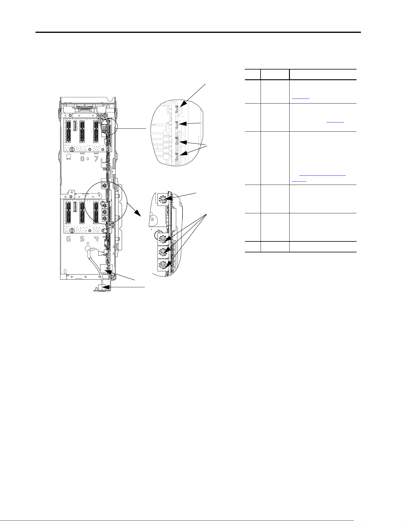
Components
Features
The features of the built-in EtherNet/IP interface include the following:
• Switches are used to set an IP address before power is applied to the
drive. Other methods are also available to configure the IP address:
– Interface parameters
– BOOTP (Bootstrap Protocol) server
– DHCP (Dynamic Host Configuration Protocol) server
• Configuration tool compatibility between the built-in EtherNet/IP
interface and host drive:
– PowerFlex 20-HIM-A6 or 20-HIM-C6S HIM (Human Interface
Module) on the drive, if installed
– Connected Components Workbench™ (CCW) software, release 10
or later
• Indicators that report the status of the built-in EtherNet/IP interface
and network communication. They are visible when the drive cover is
open or closed.
• Controller hierarchy that can be configured to transmit data to and
from a controller.
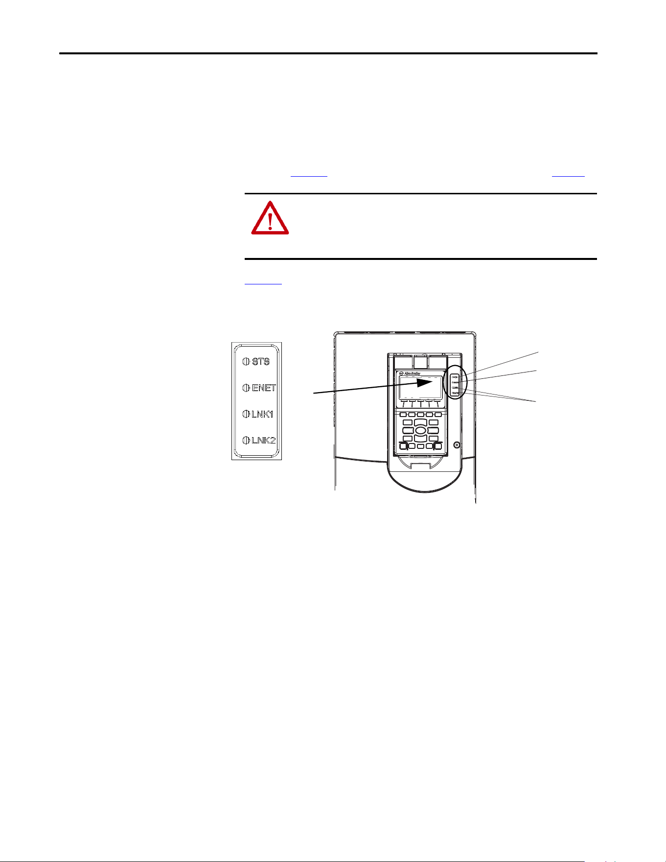
Item Part Description
1Status
Indicator -
ENET
Indicates the overall status of
network communication. See
Chapter 6, Troubleshooting.
2Status
indicators -
LNK1 and
LNK2
Indicates the status of the
network link to each of the two
physical ports. See Chapter 6,
Troubleshooting.
3 IP Address
Switches
Sets the IP address of the interface
(port 0) when not using any of
these other methods:
• Interface parameters
•BOOTP server
• DHCP server firmware
See Setting the IP Address on
page 26 for details.
4Ethernet
Connectors
RJ45 connectors for the Ethernet
cable. The connectors are CAT-5
compliant to deliver data over a
100 Base-TX Ethernet networks.
5 DPI™ Port 2
and 3
Cable connection for DPI port 2
handheld and remote options. DPI
port 3 is available by using a DPI
splitter part number 1203-S03.
6 Reserved
Drive Control Pod
Drive STS Indicator
Components that are shown have the
HIM bezel open and the drive cover
removed
1
3
4
5
2
6
Ones
Position
Hundreds
Position
Tens
Position
Rockwell Automation Publication 750COM-UM009A-EN-P - May 2017 19
Getting Started Chapter 1
• Parameter-configured 32-bit datalinks in the I/O to meet application
requirements: 16 datalinks to write data from the network to the drive,
and 16 datalinks to read data to the network from the drive.
•Explicit Messaging support.
• User-defined fault actions to determine how the built-in
EtherNet/IP interface and its host PowerFlex 755T drive respond to the
following:
– I/O messaging communication disruptions (Comm Flt Action)
– Controllers in Program mode (Idle Flt Action)
– Explicit Messaging disruptions for drive control via PCCC or the
CIP based network Assembly Object (Msg Flt Action)
• Automatic Device Configuration (ADC), an RSLogix 5000 software,
and Studio 5000 environment feature, which support the automatic
downloads of configuration data.
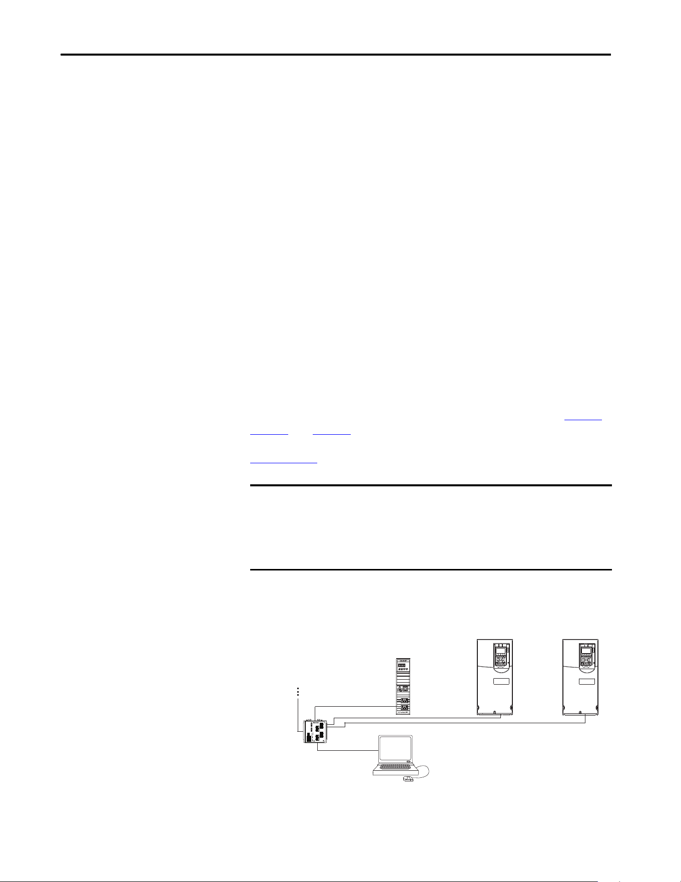
Dual Ethernet Ports
Dual Ethernet ports provide connection for star, linear, or Device Level Ring
(DLR) network topologies.
Examples of different EtherNet/IP network topologies are shown in Figure 1
,
Figure 2
, and Figure 3. For information about linear and Device Level Ring
(DLR) topologies, see EtherNet/IP built-in Switch Technology, publication
ENET-AP005
.
Figure 1 - Connecting the Ethernet Cable in a Star Topology Network
IMPORTANT The adapter has EtherNet/IP built-in switch technology, and ENET1 and
ENET2 network ports to connect to a linear or Device Level Ring (DLR)
network in a subnet.
You cannot use the ENET1 and ENET 2 network ports as two network
interfaces that are connected to two different Internet Protocol (IP) subnets.
Controller
PowerFlex 755T drives
(1)
External
Ethernet
Switch
Computer with
Ethernet Connection
To other
EtherNet/IP
networks
(1)
The Ethernet cable can be connected to the adapters ENET1 or ENET 2 network port.
20 Rockwell Automation Publication 750COM-UM009A-EN-P - May 2017
Chapter 1 Getting Started
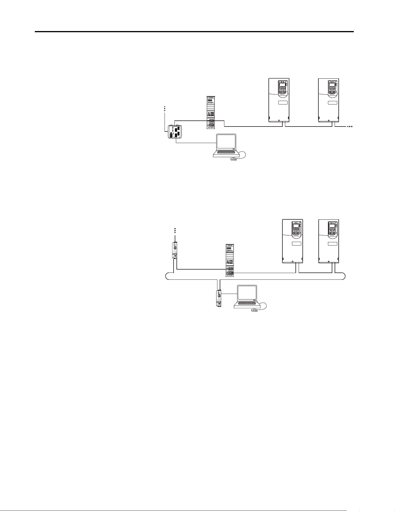
Figure 2 - Connecting the Ethernet Cable in a Linear Topology Network
Figure 3 - Connecting the Ethernet Cable in a DLR Topology Network
Required Equipment
Some required equipment used with the built-in EtherNet/IP interface is
shipped with the drive. The sections that follow describe some of the other
user-supplied equipment that is also required.
Equipment Shipped with the Drive
Since the EtherNet/IP interface is built in the main control board in the
PowerFlex 755T drive, it is always a part of the drive. There are no separate
physical installation instructions for the interface.
Controller
PowerFlex 755T drives
(1)
External
Ethernet Switch
Computer with
Ethernet Connection
To other
EtherNet/IP
networks
(1)
The adapters ENET1 and ENET2 network ports are both used.
Controller
PowerFlex 755T drives
(1)
Computer with
Ethernet Connection
To other
EtherNet/IP
networks
1783-ETAP
1783-ETAP
(1)
The adapters ENET1 and ENET2 network ports are both used.

Rockwell Automation Publication 750COM-UM009A-EN-P - May 2017 21
Getting Started Chapter 1
User-supplied Equipment
To configure the built-in EtherNet/IP interface, you must supply the
following:
• A small flat-blade screwdriver for setting the network address switches.
• An Ethernet cable (for details, see the EtherNet/IP Media Planning and
Installation Manual, ODVA publication 148, available on the ODVA
website at http://odva.org/Home/ODVATECHNOLOGIES/
EtherNetIP/EtherNetIPLibrary/tabid/76/Default.aspx). Note: A user
name and password are required to access the ODVA publications.
• An Ethernet switch (for details, see the Ethernet Design Considerations
Reference Manual, publication ENET-RM002
).
Configuration Tool Options
Any of the following configuration tools can be used:
• PowerFlex 20-HIM-A6 or 20-HIM-C6S HIM
• Connected Components Workbench (CCW) software release 10 or
later
• Connected Components Workbench is the recommended standalone
software tool for use with PowerFlex drives. You can obtain a free copy
by internet download at the Product Compatibility and Download
Center, which is located at http://
compatibility.rockwellautomation.com/Pages/home.aspx.
• Controller configuration software, such as RSLogix 5000 software,
version 20, or Studio 5000 Logix Designer® application, version 21 and
later.
• Automatic Device Configuration (ADC), an RSLogix 5000 and
Studio5000 software feature that supports the automatic download of
configuration data. The download occurs as the Logix controller
establishes an EtherNet/IP network connection to a PowerFlex 755TR,
755TL, or 755TM drive and its associated peripherals. The AOP must
be installed for ADC to be functional with Studio 5000 or RSLogix in
versions newer than version 30. After version 30, the AOP comes
preinstalled in Studio 5000.
• A computer connection to the EtherNet/IP network.

22 Rockwell Automation Publication 750COM-UM009A-EN-P - May 2017
Chapter 1 Getting Started
Choose an Ethernet Switch
If the built-in EtherNet/IP interface is used to communicate with a
controller that has multicast connections, a managed switch that
supports IGMP snooping is suggested. EtherNet/IP implicit (I/O)
messaging can be configured to use IP multicast to distribute I/O
control data, which is consistent with the CIP-based network Producer/
Consumer model. If multiple built-in EtherNet/IP interfaces are
connected to the switch in a redundant configuration, a managed switch
is required. A managed switch also provides useful diagnostic features
such as port mirroring.
The built-in EtherNet/IP interface, RSLogix 5000 software version 20,
Studio 5000 Logix Designer application version 21 and later, and a
Logix controller all support unicast connections. Unicast is the default
setting when adding the drive to the I/O controller. When all built-in
EtherNet/IP interfaces are installed as unicast devices, then an IGMP
snooping (managed) switch is not needed.
The choice of a switch involves many factors. See publication ENET-
RM002 for details.

Rockwell Automation Publication 750COM-UM009A-EN-P - May 2017 23
Getting Started Chapter 1
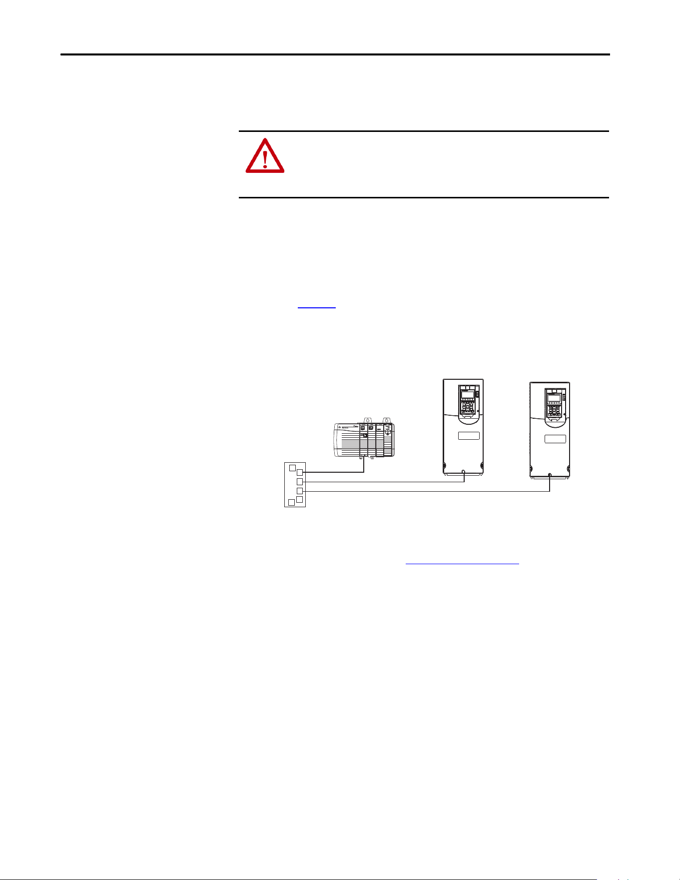
Safety Precautions
Read the following safety precautions carefully.
ATTENTION:
• Risk of injury or equipment damage exists. Only personnel familiar with
drive and power products and the associated machinery can plan or
implement the installation, start up, configuration. Only qualified personnel
can perform subsequent maintenance of the drive by using this built-in
interface. Failure to comply can result in injury and/or equipment damage.
• Risk of equipment damage exists. The built-in interface contains
electrostatic discharge (ESD) sensitive parts that can be damaged if you do
not follow ESD control procedures. ESD control precautions are required
when handling the interface. If you are unfamiliar with ESD control
procedures, see Guarding Against Electrostatic Damage, publication
8000-4.5.2
.
• Risk of injury or equipment damage exists. If the interface is transmitting
control I/O to the drive, the drive can fault when you reset the interface.
Determine how your drive responds before resetting the interface.
• Risk of injury or equipment damage exists. Built-in adapter 0:360 - [Comm
Flt Action], 0:361 - [Idle Flt Action], and 0:363 - [Msg Flt Action] let
you determine the action of the interface and drive when one of the
following occurs:
- I/O communication is disrupted
- The controller is in Program Mode
- Explicit Messaging for drive control is disrupted
By default, these parameters fault the drive. You can configure these
parameters so that the drive continues to run; however, verify that the
settings of these parameters do not create a risk of injury or equipment
damage. When commissioning the drive, verify that your system responds
correctly to various situations (for example, a disconnected cable or a
controller in Program Mode).
• Risk of injury or equipment damage exists. When a system is configured for
the first time, there can be unintended or incorrect machine motion.
Disconnect the motor from the machine or process during initial system
testing.
• Risk of injury or equipment damage exists. The examples in this publication
are intended solely for purposes of example. There are many variables and
requirements with any application. Rockwell Automation® does not assume
responsibility or liability (to include intellectual property liability) for actual
use of the examples that are shown in this publication.

24 Rockwell Automation Publication 750COM-UM009A-EN-P - May 2017
Chapter 1 Getting Started
Notes:

Rockwell Automation Publication 750COM-UM009A-EN-P - May 2017 25
Chapter 2
Configure the Interface
This chapter provides instructions and information for setting the parameters
to configure the built-in EtherNet/IP interface.
For a list of parameters, see Appendix C
, Parameter List. For definitions of
terms in this chapter, see the Glossary
.
Topic Page
Configuration Tools 26
Setting the IP Address 26
Connecting the Interface to the Network 29
Apply Power 30
Start-up Status Indications 31
Configuring and Verifying Key Drive Parameters 33
Use Interface Parameters to Set the IP Address 33
Using the PowerFlex 20-HIM-A6 or 20-HIM-C6S to Access Parameters 34
Using a BOOTP or DHCP Server 36
Setting the Data Rate 40
Setting Communication Hierarchy 41
Setting a Controller Hierarchy 41
Setting a Fault Action 44
Changing the Fault Action 44
Setting the Fault Configuration Parameters 45
Resetting the Interface 45
Restore Interface Parameters to Default Configurations 45
Viewing the Interface Status Using Parameters 47
Updating the Interface Firmware 47
26 Rockwell Automation Publication 750COM-UM009A-EN-P - May 2017
Chapter 2 Configure the Interface
Configuration Tools
The built-in EtherNet/IP interface stores parameters and other information in
nonvolatile storage (NVS). The following tools can be used to access the
interface parameters.
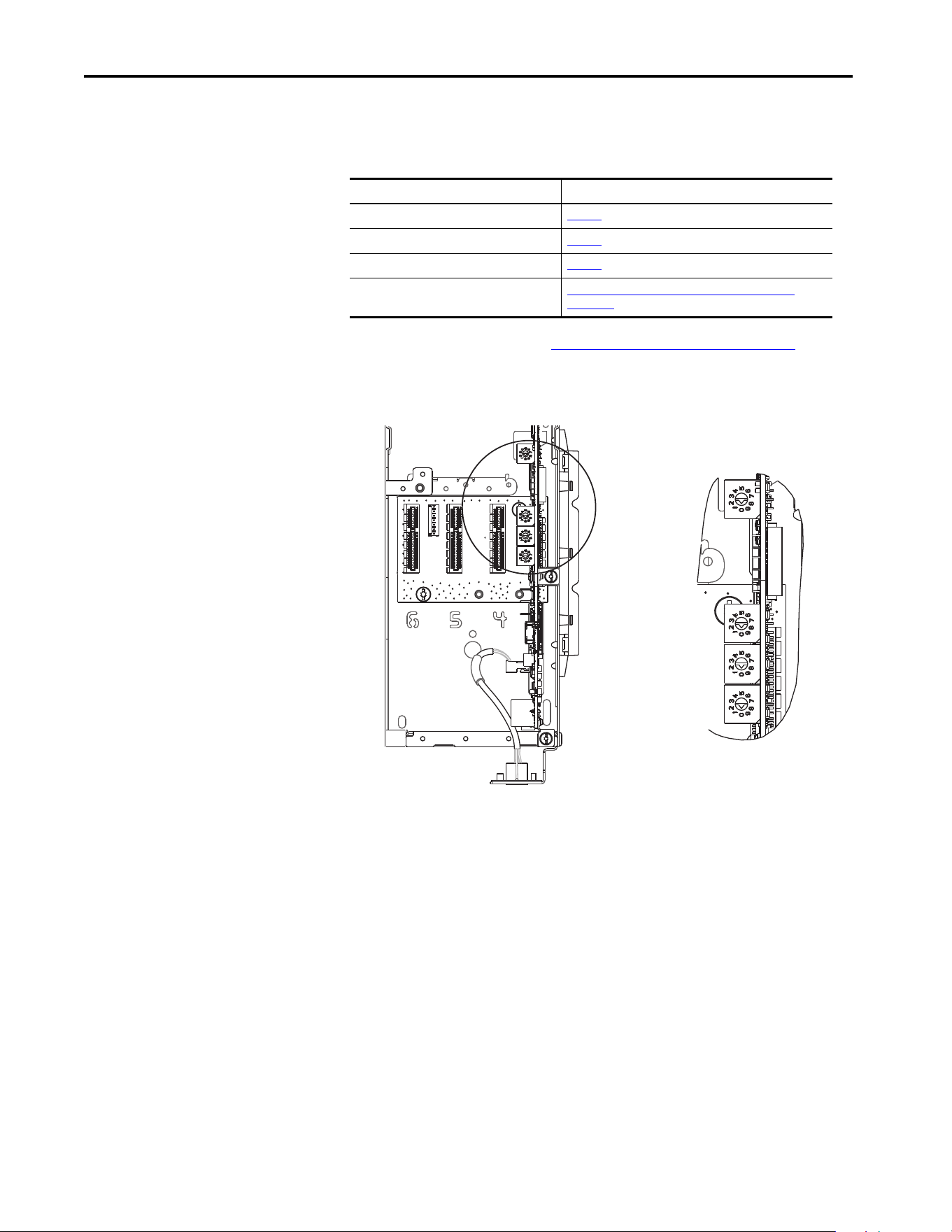
Setting the IP Address
Figure 4 - Setting the IP Address Switches
There are four ways to configure the built-in EtherNet/IP interface IP address:
• Interface Rotary Switches — Use the switches when working on a
simple, isolated network (with IP addresses in the range, 192.168.1.xxx),
and you prefer a simplified node addressing method that has other
products with switches to set their IP addresses.
The three interface switches are grouped near the middle of the drive.
These switches are read when the drive powers up, and represent three
decimal digits from top to bottom. If set to a valid address (001…254),
the interface uses that value as the last octet of its IP address
(192.168.1.xxx, where xxx = the rotary switch settings), along with a
subnet mask of 255.255.255.0 and a gateway address of 192.168.1.1.
Also, the setting for interface 0:300 - [Net Addr Sel] is automatically
ignored.
Tool See
PowerFlex® 20-HIM-A6 or 20-HIM-C6S HIM page 34
BOOTP server page 36
DHCP server page 36
Connected Components Workbench™ (CCW)
software, release 10 or later
(1)
(1) CCW release10 requires an additional software updates to add PowerFlex 755T support. It is downloadable from the
Product Compatibility and Download Center at: http://compatibility.rockwellautomation.com/Pages/home.aspx
http://compatibility.rockwellautomation.com/Pages/
home.aspx, or online help (installed with the software)
Ones
Position
Hundreds
Position
Tens
Position

Rockwell Automation Publication 750COM-UM009A-EN-P - May 2017 27
Configure the Interface Chapter 2
See Figure on page 28 and its accompanying table for switch settings
and their related descriptions.
• Interface Parameters — Use interface parameters for more flexibility
when configuring the IP address. To use parameters as the source for the
IP address, set the rotary switches to 999. Set 0:300 - [Net Addr Sel] to
‘1’ (Parameters). The IP address, subnet mask, and gateway address
come from the values set using the associated interface 0:302...313.
• BOOTP — Use BOOTP when you want to configure an IP address,
subnet mask, and gateway address for the interface by using a BOOTP
server. To use BOOTP as the source for the IP address, set the rotary
switches to 999. Set 0:300 - [Net Addr Sel] to ‘2’ (BOOTP).
Record the interface hardware Ethernet (MAC) address from the
Ethernet address label on the main control board of the drive. This
address is used when configuring the BOOTP server (see Using a
BOOTP or DHCP Server on page 36 for details).
• DHCP (Dynamic Host Configuration Protocol) Use DHCP when
you want to configure an IP address, subnet mask, and gateway address
for the interface by using a DHCP server. To use DHCP as the source
for the IP address, set the rotary switches to 999.
Set 0:300 - [Net Addr Sel] to ‘3’ (DHCP).
Make note of the Ethernet (MAC) address for the hardware interface
that is shown on the Ethernet address label on the main control board of
the drive. The MAC is used when configuring the DHCP server. See
Using a BOOTP or DHCP Server on page 36
for details.
IMPORTANT When using the interface rotary switches, set the IP address before power is
applied because the interface uses the switch settings that it detects when it
first receives power.
TIP If the PowerFlex 755TM, 755TR, or 755TL drive is connected to a Stratix®
6000 or Stratix 8000 managed Ethernet switch and the drive is set for BOOTP
or DHCP mode, the ‘dynamic IP address assignment by port’ (Stratix 6000)
or ‘DHCP persistence’ (Stratix 8000) feature can be used to set the IP address
for the drive. For more details, see the Stratix 6000 Ethernet Managed
Switch User Manual, publication 1783-UM001
, or the Stratix 8000 and
Stratix 8300 Ethernet Managed Switches User Manual, publication 1783-
UM003.
IMPORTANT When the DHCP lease expires, the adapter stops communicating on the
network. A power cycle or option module reset is required.

28 Rockwell Automation Publication 750COM-UM009A-EN-P - May 2017
Chapter 2 Configure the Interface
The switch settings can be verified by viewing Port 0 Diagnostic Item number
68 (page 113
) with any of the following drive configuration tools:
• PowerFlex 20-HIM-A6 or 20-HIM-C6S HIM
• Connected Components Workbench software, release 10 or later
Also, you can use 0:301 - [Net Addr Src], a read-only parameter, to verify the
active setting for 0:300 - [Net Addr Sel].
IMPORTANT Regardless of the method that is used to set the interface IP address, each
node on the EtherNet/IP network must have a unique IP address. To change
an IP address, you must set the new value and then remove and reapply
power to (or reset) the interface.
Settings Description
001…254 The interface uses the rotary switch settings for the IP address (192.168.1.xxx, where xxx = the
rotary switch settings). The value that is stored in 0: 300 - [Net Addr Sel] is automatically
ignored.
888 Resets the interface IP address and other EtherNet/IP communication settings to factory
defaults. Thereafter, the drive must be powered down, the switches set to a correct value
(001…254 or 999), and then the drive must be powered up again to accept the new address.
999 Disables the rotary switches, and requires using one of the following:
• 0:300 - [Net Addr Sel] selects the source for the interface IP address, which is one of the
following:
– Interface Parameters
–BOOTP server (default)
– DHCP server firmware
Any other
setting
Reserved.
Rockwell Automation Publication 750COM-UM009A-EN-P - May 2017 29
Configure the Interface Chapter 2
Connecting the Interface to
the Network
1. Remove power from the drive and discharge any stored power.
2. To access the drive control pod, open the drive door.
3. Use electrostatic discharge (ESD) control precautions.
4. Connect one end of an Ethernet cable to the network.
See Figure 5
for an example of wiring to an EtherNet/IP network.
Figure 5 - Connecting the Ethernet Cable to the Network
5. Route the other end of the Ethernet cable through the bottom plate of
the drive to either of the Ethernet connectors on the bottom edge of the
control board. See item 4 in Components on page 18
.
ATTENTION: Risk of injury or death exists. The PowerFlex drive can contain high
voltages that can cause injury or death. Remove power from the drive, and then
verify that power has been discharged before connecting the built-in EtherNet/IP
interface to the network. Verify that the DC bus has been discharged.
Ethernet
Switch
Controller
PowerFlex 755T drives
(each with built-in EtherNet/IP interface)

30 Rockwell Automation Publication 750COM-UM009A-EN-P - May 2017
Chapter 2 Configure the Interface
Apply Power
1. Close the cabinet door for the drive.
2. Apply power to the drive.
The built-in EtherNet/IP interface receives its power from the drive.
3. Check the status indicators either by using status parameters, HIM
status, or the software tool status.
When you apply power to the built-in EtherNet/IP interface for the first
time, its EtherNet/IP status indicator is steady green or flashes green
after an initialization.
If it is red or remains off, there is a problem. See Chapter 6
,
Troubleshooting.
ATTENTION: Risk of equipment damage, injury, or death exists. Unpredictable
operation can occur if you fail to Verify that parameter settings are compatible
with your application. Verify that settings are compatible with your application
before power is applied to the drive.
ATTENTION: Wear personal protective equipment (PPE) to avoid death or injury
when applying power with the drive door open.
Rockwell Automation Publication 750COM-UM009A-EN-P - May 2017 31
Configure the Interface Chapter 2
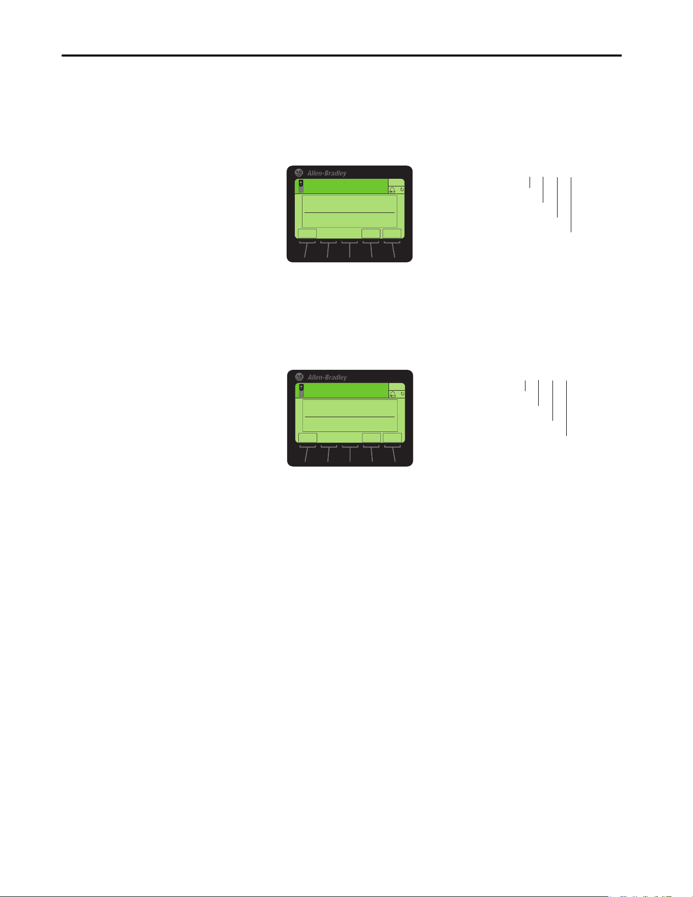
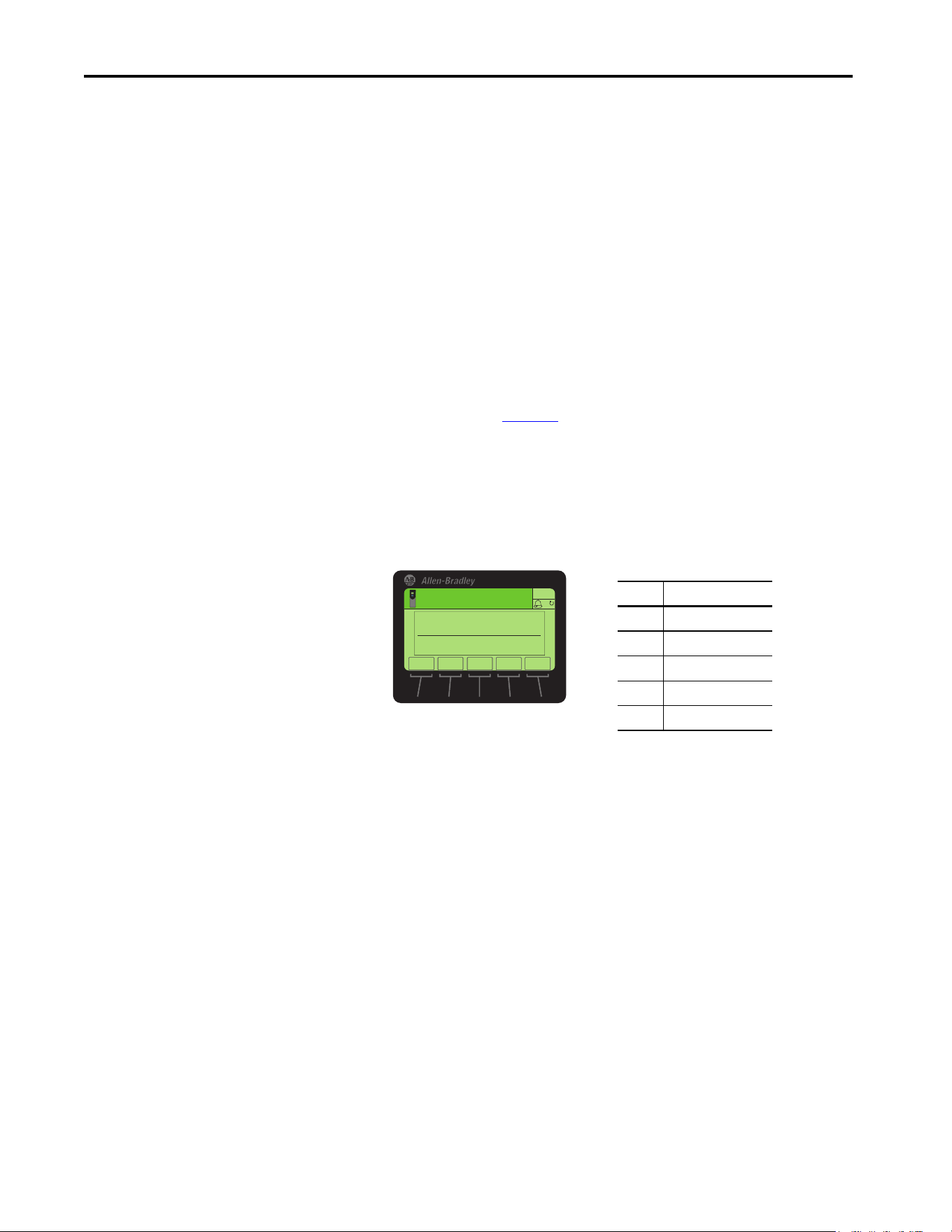
Start-up Status Indications
After power is applied, the drive STS (status) indicator and the built-in
EtherNet/IP interface ENET, LNK1, and LNK2 status indicators can be
monitored via status parameters, HIM status, and the software tool status, if
personal protective equipment is worn, they can also be viewed on the front of
the drive (Figure 6
). Possible start-up status indications are shown in Tab le 1.
Figure 6
is an example of a type of HIM available. Your HIM may appear
differently or in a different location.
Figure 6 - Drive and Interface Status Indicators
ATTENTION: Risk of injury or equipment damage exists. When a system is
configured for the first time, there can be unintended or incorrect machine
motion. Disconnect the motor from the machine or process during initial
system testing.
1
2
3

32 Rockwell Automation Publication 750COM-UM009A-EN-P - May 2017
Chapter 2 Configure the Interface
After verifying correct operation, place the drive HIM bezel to its closed
position and install the drive cover. For more details on status indicator
operation, see page 118
.
Table 1 - Drive and Interface Start-up Status Indications
Item Name Color State Description
Drive STS Indicator
1 STS (Status) Green Flashing Drive ready but is not running, and no faults are present.
Steady Drive is running and no faults are present.
Yellow Flashing When running, a type 2 (non-configurable) alarm condition exists – the drive
continues to run. When stopped, a start inhibit condition exists and the drive
cannot be started (see drive 0:603 - [Start Inhibit]).
Steady A type 1 (configurable) alarm condition exists, but the drive continues to run.
Red Flashing A major fault has occurred. The drive stops. it cannot be started until the fault
condition is cleared.
Steady A non-resettable fault has occurred.
Red/Yellow Flashing
Alternately
A minor fault has occurred. If not enabled a minor fault, acts like a major fault. If
minor faults are enabled and the drive is running, the drive continues to run. The
system is brought to a stop under system control. The fault must be cleared to
continue.
Yellow/
Green
Flashing
Alternately
When running, a type 1 (configurable) alarm exists and the drive continues to
run.
Green/Red Flashing
Alternately
The drive is updating firmware.
Built-in EtherNet/IP interface Status Indicators
2 ENET Unlit Off The interface and/or network is not powered, the interface is not properly
connected to the network, or the interface needs an IP address.
Red Flashing A network connection has timed out, the rotary switches have been changed
since power-up, or the network configuration is invalid.
Steady The interface failed the duplicate IP address detection test or its DCHP lease has
expired.
Red/Green Flashing
Alternately
The interface is performing a self-test.
Green Flashing The interface is properly connected, but the drive is not controlled by the
network.
Steady The interface is properly connected, and the drive is controlled by the network.
3LNK1 and
LNK2
Unlit Off The interface does not have an Ethernet link.
Green
(100 Mbps)
or
Yellow
(10 Mbps)
Flashing The interface is properly connected and is transmitting or receiving data packets
on the network.
Steady The interface is properly connected, but is not transmitting or receiving on the
network.

Rockwell Automation Publication 750COM-UM009A-EN-P - May 2017 33
Configure the Interface Chapter 2
Configuring and Verifying Key Drive Parameters
The PowerFlex 755T drive can be separately configured for the command logic
and reference functions in various combinations. For example, you could set
the drive to have the logic command come from a peripheral or terminal block
but have the reference come from the network. Or you could set the drive to
have its control come from the network with the reference that comes from
another peripheral or terminal block. Or you could set the drive to have both
its logic command and reference come from the network.
The following steps in this section assume that the drive receives the logic
command and reference from the network.
1. To access the required parameters in this procedure, verify that drive
parameter 0:30 - [Access Level] is set to ‘1’ (Advanced) or ‘2’ (Expert).
2. To set the drive velocity reference, use drive 10:1800 - [VRef A Sel].
a. Set the Port field to ‘10 - Pri MtrSideCtrl’ as shown.
b. Set the Parameter field to point to Port 0, which contains the
EtherNet/IP interface.
c. Then choose Parameter 211 [Emb Enet Ref ].
3. Verify that drive 10:350 - [VRef Source] matches your entry to
10:1800 [VRef A Sel].
Any velocity reference that is commanded from the network can be
monitored by using 0:1914 - [VRef Command]. If a problem occurs,
this verification step provides the diagnostic capability to determine
whether the drive, interface, or the network is the cause.
4. If hard-wired discrete digital inputs are not used to control the drive,
verify that all unused digital input drive parameters are set to ‘0’ (Not
Used). These parameters are located in Port 0, in the file Feedback & I/
O, group Command.
Use Interface Parameters to
Set the IP Address
By default, the interface is configured to use a DHCP server as the source for
the IP address interface, subnet mask, and gateway address. To use interface
parameters instead, you must first change the source for the node address to
Parameters by using 0:300 - [Net Addr Sel]. Set the associated interface
parameters as described in the following subsections.

34 Rockwell Automation Publication 750COM-UM009A-EN-P - May 2017
Chapter 2 Configure the Interface
Using the PowerFlex 20-HIM-A6 or 20-HIM-C6S to Access
Parameters
If your drive has an enhanced PowerFlex 20-HIM-A6 or 20-HIM-C6S HIM,
it can be used to access parameters in the interface.
1. Display the Status screen, which is shown on HIM power-up.
2. Use the or key to scroll to the Port 0 where the built-in
EtherNet/IP interface resides.
3. To display the Jump to Param # entry popup box, press the PAR# soft key.
4. Use the numeric keys to enter the desired parameter number, or use the
▲ or ▼ softkey to scroll to the desired parameter number.
For details on how to view and edit parameters, see the
PowerFlex 20-HIM-A6/-C6S HIM (Human Interface Module) User Manual,
publication 20HIM-UM001
.
Change the Source for the Network Address
1. Verify that the IP address switches (Figure on page 28) are set to 999.
2. Set the value of 0:300 - [Net Addr Sel] to ‘1’ (Parameters).
3. Reset the interface by cycling power to the drive or by using the HIM
Reset Device function that is located in the DIAGNOSTIC folder of
the drive.
4. Set the IP address, subnet mask, and gateway address by using interface
parameters. Perform the steps in the following subsections.
Value Setting
1 Parameters
2BOOTP
3 DHCP (default)
ESC
ENTER
Stopped
0.00 Hz
AUTO
F
▲▼
Edit Net Addr Sel
Parameters 1
1<<3
Rockwell Automation Publication 750COM-UM009A-EN-P - May 2017 35
Configure the Interface Chapter 2
Set the IP Address
1. Verify 0:300 - [Net Addr Sel] is set to ‘1’ (Parameters).
2. Set the value of 0:302 - [IP Addr Cfg 1] … 305 - [IP Addr Cfg 4] to a
unique IP address.
Set the Subnet Mask
1. Verify 0:300 - [Net Addr Sel] is set to ‘1’ (Parameters).
2. Set the value of 0:306 - [Subnet Cfg 1] … 309 - [Subnet Cfg 4] to the
desired value for the subnet mask.
• The PowerFlex 755T subnet mask cannot be 0.0.0.0.
• The PowerFlex 755T gateway address can be 0.0.0.0. If the gateway
address is 0.0.0.0, the PowerFlex 755T can only communicate with
devices on the same subnet as the drive. It is not able to communicate
with devices on other subnets.
• If the PowerFlex 755T gateway address is not set to 0.0.0.0, then it must
be set to an address that is on the same subnet as the drive's IP address.
Default = 0.0.0.0 255.255.255.255
[IP Addr Cfg 1]
[IP Addr Cfg 2]
[IP Addr Cfg 3]
[IP Addr Cfg 4]
Edit IP Addr Cfg 1
0
0 << 255
ESC
ENTER
Stopped
0.00 Hz
AUTO
F
Default = 0.0.0.0 255.255.255.255
[Subnet Cfg 1]
[Subnet Cfg 2]
[Subnet Cfg 3]
[Subnet Cfg 4]
Edit Subnet Cfg 1
0
0<<255
ESC
ENTER
Stopped
0.00 Hz
AUTO
F

36 Rockwell Automation Publication 750COM-UM009A-EN-P - May 2017
Chapter 2 Configure the Interface
Set the Gateway Address
1. Verify 0:300 - [Net Addr Sel] is set to ‘1’ (Parameters).
2. Set the value of 0:310 - [Gateway Cfg 1] … 313 - [Gateway Cfg 4] to
the IP address of the gateway device.
• The PowerFlex 755T subnet mask cannot be 0.0.0.0.
• The PowerFlex 755T gateway address can be 0.0.0.0. If the gateway
address is 0.0.0.0, the PowerFlex 755T can only communicate with
devices on the same subnet as the drive. It is not able to communicate
with devices on other subnets.
• If the PowerFlex 755T gateway address is not set to 0.0.0.0, then it must
be set to an address that is on the same subnet as the drive's IP address.
3. Reset the interface by cycling power to the drive or by using the HIM
Reset Device function that is located in the DIAGNOSTIC folder of
the drive.
Using a BOOTP or DHCP
Server
There are various BOOTP and DHCP servers available. The following
instructions use the Rockwell Automation® BOOTP/DHCP Server. This is a
free standalone program that incorporates the functionality of standard
BOOTP and DHCP utilities with a graphical interface page installed
automatically as part of the RSLinx software. It is available at the Product
Compatibility and Download Center (PCDC) at http://
compatibility.rockwellautomation.com/Pages/ home.aspx. From the website,
choose the ‘Find Downloads’ link and search for the word ‘BOOTP’). See the
Read-me file and online Help for directions and more information.
Default = 0.0.0.0 255.255.255.255
[Gateway Cfg 1]
[Gateway Cfg 2]
[Gateway Cfg 3]
[Gateway Cfg 4]
Edit Gateway Cfg 1
0
0<<255
ESC
ENTER
Stopped
0.00 Hz
AUTO
F
TIP If the PowerFlex 755TM, 755TR, or 755TL drive is connected to a Stratix 6000
or Stratix 8000 managed Ethernet switch and the drive is set for BOOTP or
DHCP mode, the ‘dynamic IP address assignment by port’ (Stratix 6000) or
‘DHCP persistence’ (Stratix 8000) feature can be used to set the IP address
for the drive. For more details, see the Stratix 6000 Ethernet Managed
Switch User Manual, publication 1783-UM001
, or the Stratix 8000 and
Stratix 8300 Ethernet Managed Switches User Manual, publication 1783-
UM003.
TIP If you prefer to configure the IP address, subnet mask, and gateway address
by using interface parameters, set interface 0:300 - [Net Addr Sel] to ‘0’
(Parameters). For details, see Use Interface Parameters to Set the IP Address
on page 33.
Rockwell Automation Publication 750COM-UM009A-EN-P - May 2017 37
Configure the Interface Chapter 2
1. Depending on the type of server (BOOTP or DHCP) being used, set
0:300 - [Net Addr Sel] to either ‘2’ (BOOTP) or ‘3’ (DHCP)
respectively.
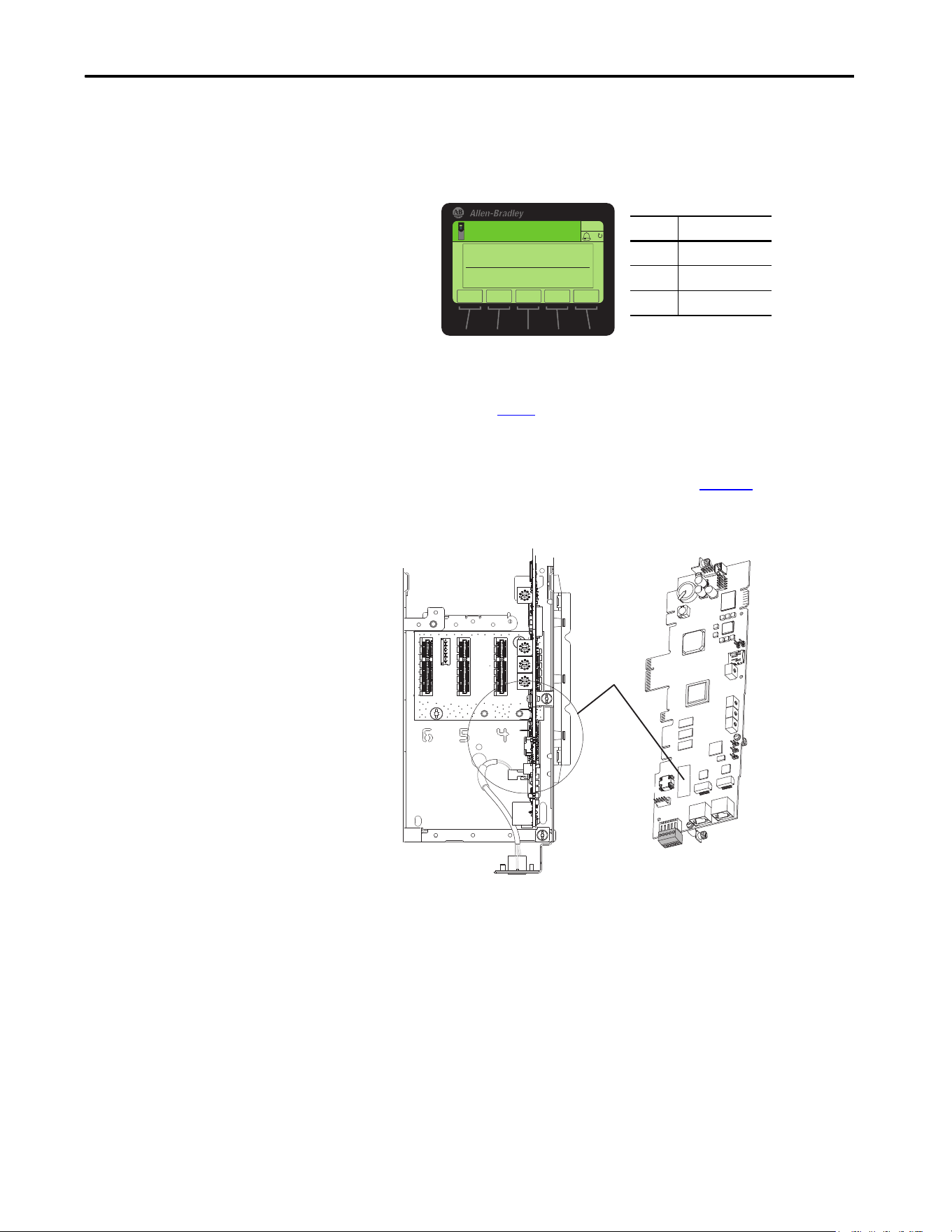
2. Make note of the Ethernet Address (MAC) of the interface hardware,
which is used in step
7.
There are two ways to find the media access control (MAC) address:
• Remove the drive cover and locate the hardware Ethernet Address
label on the main control board of the drive (Figure 7
).
Figure 7 - Location of the Interface Hardware Address Label
• Use the HIM to scroll to drive Port 0 and access the built-in
EtherNet/IP interface DIAGNOSTIC folder screen. Then scroll to
Diagnostic Items 43…48 (HW Addr 1…6) to view the hardware
Ethernet Address (MAC) of the interface. Finally, convert these
decimal values to hex values.
Value Setting
1 Parameters
2BOOTP
3DHCP (default)
ESC
ENTER
Stopped
0.00 Hz
AUTO
F
Edit Net Addr Sel
1<<3
With drive firmware 1.xxx or later
Ethernet
Address
(MAC)
Label
Location
Drive Control Pod
Ethernet Connectors
Front View - Main Control Board
38 Rockwell Automation Publication 750COM-UM009A-EN-P - May 2017
Chapter 2 Configure the Interface
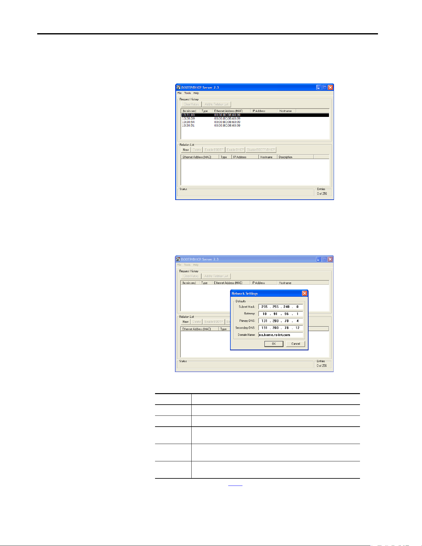
3. On a computer that is connected to the EtherNet/IP network, start the
BOOTP/DHCP software.
The BOOTP/DHCP Server dialog box appears.
To configure devices on your EtherNet/IP network, you must configure
settings in the BOOTP/DHCP software to match the network.
4. From the Tools menu, choose Network Settings.
The Network Settings dialog box opens.
5. Edit the following:
Box Type
Subnet Mask
(1)
(1) For definitions of these terms, see the Glossary.
The subnet mask for the built-in EtherNet/IP of the interface network.
Gateway
(1)
The IP address of the gateway device on the network of the interface.
Primary DNS Optional - the address of the primary Domain Name Service (DNS) server that is used
to locate devices on the network by name instead of by IP address.
Secondary DNS Optional - the address of the secondary DNS server to be used on the local end of the
link for negotiating with remote devices when the primary DNS server is unavailable.
Domain Name Optional - The text name that corresponds to the network containing the BOOTP/DHCP
server and the drive being configured.
Rockwell Automation Publication 750COM-UM009A-EN-P - May 2017 39
Configure the Interface Chapter 2
6. Click OK to apply the settings.
Devices on the network that issue BOOTP/DHCP requests appear in
the BOOTP/DHCP Request History list.
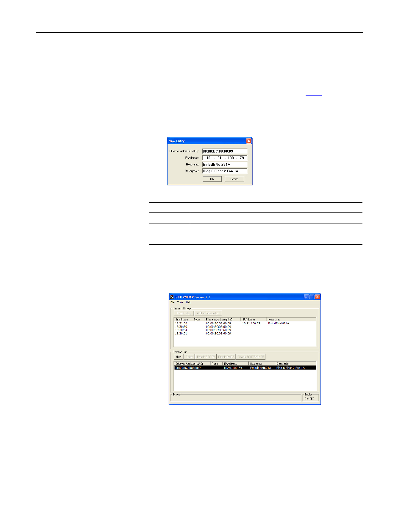
7. In the BOOTP/DHCP Request History list, either double-click the
Ethernet Address (MAC) of the interface noted in step 2
, or click New
in the Relation List.
The New Entry dialog box appears. In the first instance, the Ethernet
Address (MAC) is automatically entered. In the latter instance, it must
be manually entered.
8. Edit the following:
9. Click OK to apply the settings.
After the interface makes the next BOOTP or DHCP request, the
interface appears in the Relation List with the new settings.
10. After the BOOTP/DHCP Server has provided an IP address, to assign
this configuration permanently to the interface, select the device in the
Relation List, and click Disable BOOTP/DHCP.
When power is cycled on the interface, it uses the configuration that you
assigned it and does not issue new BOOTP or DHCP requests.
Box Type
IP Address
(1)
(1) For definition of this term, see the Glossary.
A unique IP address for the interface
Host Name Optional - a text name for the drive being configured
Description Optional - text to describe the device that is saved only in the BOOTP/DHCP software
40 Rockwell Automation Publication 750COM-UM009A-EN-P - May 2017
Chapter 2 Configure the Interface
11. From the File menu, choose Save to save the Relation List.
Setting the Data Rate
By default, the interface is set to autodetect, so it automatically detects the data
rate and duplex setting that is used on the network. If you must set a specific
data rate and duplex setting, use the 0:314 - [Net Rate Cfg 1] and 0:316 -
[Net Rate Cfg 2] values. These values determine the Ethernet data rate and
duplex settings that the interface uses to communicate. For definitions of data
rate and duplex, see the Glossary
.
1. Verify that the Ethernet cable is connected to Ethernet port 1 or port 2
to change the data rate or duplex setting. Port 1 is the connector closest
to the front edge of the control board.
2. Set the value of 0:314 - [Net Rate Cfg 1] or 0:316 - [Net Rate Cfg 2]
to the data rate at which your network is operating.
3. Reset the interface by cycling power to the drive or by using the Reset
Device function of the HIM located in the DIAGNOSTIC folder for
the drive.
TIP To enable BOOTP or DHCP for an interface that has had BOOTP/DHCP
disabled, first select the interface in the Relation List. Then, depending on
the type of server, click Enable BOOTP or Enable DHCP and, lastly, reset
the interface or power cycle the drive.
TIP Auto detection of the data rate and duplex works only if the device (usually
a switch) on the other end of the cable is also set to detect the rate/duplex.
If one device is using fixed data rate/duplex, the other device must use the
same fixed settings.
Value Data Rate
0 Autodetect (default)
1 10 Mbps Full
2 10 Mbps Half
3 100 Mbps Full
4 100 Mbps Half
ESC
ENTER
Stopped
0.00 Hz
AUTO
F
Edit Net Rate Cfg 1
Autodetect 0
0<<4
▲▼

Rockwell Automation Publication 750COM-UM009A-EN-P - May 2017 41
Configure the Interface Chapter 2
Setting Communication
Hierarchy
A hierarchy determines the type of device with which the interface exchanges
data. In a Controller hierarchy, the interface exchanges data with the
ControlLogix® controller or another communication bridge.
When a multicast I/O connection is used or when the interface does not have a
valid gateway address, the controller must be on the same IP subnet as the
interface to establish an I/O connection. See IP addresses in the Glossary
for
information about IP subnets.
Setting a Controller Hierarchy
To set the Controller hierarchy, follow the instructions in this section to enable
datalinks to read and write data.
Enable Datalinks to Write Data
The controller output image (controller outputs-to-drive) always contains the
logic command and reference fields. It can also have 0...16 additional 32-bit
parameters (datalinks). They are configured using 0:321 - [DL From Net 01]
… 336 - [DL From Net 16]. The output connection size in the controller
determines the number of datalinks that are actively used. See the respective
controller example sections in Chapter 3
for more information on setting the
connection size.
When using a ControlLogix controller, configure the datalink parameters now
as described in this section.
0:321 - [DL From Net 01] …336 - [DL From Net 16] control which
parameters receive the values from the network. These parameters apply to the
drive, option module, or any other connected peripheral. You can use the
PowerFlex 20-HIM-A6 or 20-HIM-C6S HIM, or another drive configuration
tool, such as Connected Components Workbench software, to select the drive
or peripheral by port number and the parameter by name. As an alternate
method, set the parameter value manually by number by using this formula:
From Net Parameter Value = (10000 * Port Number) + (Destination Parameter Number)
IMPORTANT Always use the datalink parameters in consecutive numerical order. Start
with the first parameter. For example, use 0:321… 323 to configure three
datalinks to write data. Otherwise, the network I/O connection size is larger
than necessary, which needlessly increases controller response time and
memory usage.
TIP When using the ControlLogix controller and RSLogix 5000 software, version
20 and Studio 5000® environment, version 21 or later, there is no need to
configure datalink parameters. They are assigned when configuring the
RSLogix 5000 drive Add-on Profile (see Configure Input and Output Data on
page 59).

42 Rockwell Automation Publication 750COM-UM009A-EN-P - May 2017
Chapter 2 Configure the Interface
For example, if you want to use 0:321 - [DL From Net 01] to write to
Parameter 3 of an optional encoder card plugged into drive Port 5. By using
the formula, the value for 0:321- [DL From Net 01] would be (10000 * 5) +
(3) = 50003.
Follow these steps to enable datalinks to write data.
1. Set the values of only the required number of contiguous controller-to-
drive datalinks that write data to the drive and are included in the
network I/O connection.
2. Reset the drive by cycling power to the drive or by using the Reset
Device function of the HIM located in the DIAGNOSTIC folder for
the drive.
3. Since the logic command and reference are always used in the interface,
configure the parameters in the drive to accept the logic command and
reference from the interface.
When using the controller for speed reference via the interface, set two
fields in drive 10:1800 - [VRef A Sel].
a. Set the Port field for the drive (for example, 0 - PowerFlex 755T).
b. Set the Parameter field to point to the parameter containing the
reference value received from the parameter containing the reference
value that is received from the embedded EtherNet/IP interface
0:211 -[Emb Enet Ref ].
Also, verify that the mask parameters in the drive, (for example,
0:41 - [Logic Mask]) are configured to receive the desired logic
command from the interface. See the drive documentation for
details.
The interface is ready to receive input data and transfer control data
from the controller.
Next, configure the controller to recognize and transmit I/O to the interface.
See Chapter 3
, Configuring the drive in a Logix System.
Enable Datalinks to Read Data
The controller input image (drive-to-controller inputs) always contains the
logic status and feedback fields. It can also have 0...16 additional 32-bit
parameters (datalinks). They are configured using 0:340 - [DL To Net 01] …
355 - [DL To Net 16]. The input connection size in the controller determines
the number of datalinks that are actively used. See the respective controller
example sections in Chapter 3
for more information on setting the connection
size.

Rockwell Automation Publication 750COM-UM009A-EN-P - May 2017 43
Configure the Interface Chapter 2
When using a ControlLogix controller, configure the datalink parameters now
as described in this section.
0:340 - [DL To Net 01] … 355 - [DL To Net 16] configure which parameters
in the drive, interface, or any other connected peripheral send the values to the
network. Select the drive or peripheral by port number and the parameter by
name. Use the PowerFlex 20-HIM-A6 or 20-HIM-C6S HIM, or another drive
configuration tool such as Connected Components Workbench software. As
an alternate method, use this formula to set the parameter value manually by
number:
To Net Parameter Value = (10000 * Port Number) + (Origination Parameter Number)
For example, suppose that you want to use 0:340 - [DL To Net 01] to read
Parameter 2 of an optional I/O card plugged into drive Port 6. By using the
formula, the value for 0:340 - [DL To Net 01] would be (10000 * 6) + (2) =
60002.
Follow these steps to enable datalinks to read data.
1. Set the values of only the required number of contiguous drive-to-
controller datalinks that read data from the drive and are included in the
network I/O connection.
2. Reset the interface by cycling power to the drive or by using the Reset
Device function of the HIM located in the DIAGNOSTIC folder for
the drive.
The interface is configured to send output data to the controller. Configure the
controller to recognize and transmit I/O to the interface. See Chapter 3
,
Configuring the drive in a Logix System.
IMPORTANT Always use the datalink parameters in consecutive numerical order. Start
with the first parameter. For example, use 0:340…344 to configure five
datalinks to read data. Otherwise, the network I/O connection size is larger
than necessary, which needlessly increases controller response time and
memory usage.
TIP When using a ControlLogix controller and an RSLogix 5000 software, version
20 and Studio 5000 environment, version 21 or later, there is no need to
configure datalink parameters. They are assigned when configuring the
RSLogix 5000 drive Add-on Profile (see Configure Input and Output Data on
page 59).
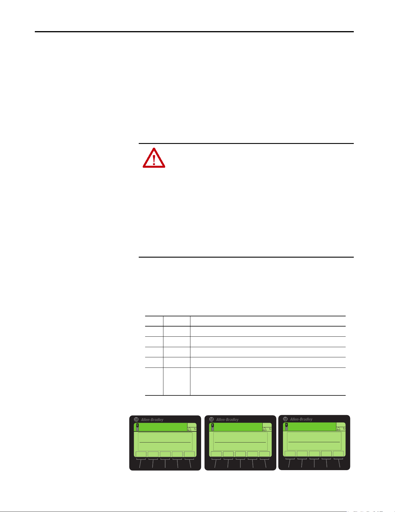
44 Rockwell Automation Publication 750COM-UM009A-EN-P - May 2017
Chapter 2 Configure the Interface
Setting a Fault Action
By default, when the drive is controlled by the network or receives information
from the network; communication is disrupted. The drive responds by
faulting, if it is using I/O from the network. Possible causes include that the
network cable is disconnected, the controller is idle (in Program mode or
faulted), or Explicit Messaging for drive control is disrupted. You can configure
another response to these faults:
• Disrupted I/O communication by using 0:360 - [Comm Flt Action]
•An idle controller by using 0:361 - [Idle Flt Action]
• Disrupted Explicit Messaging for drive control via PCCC or the CIP-
based network Assembly Object by using 0:363 - [Msg Flt Action]
Changing the Fault Action
Set the values of 0:360 - [Comm Flt Action], 361 - [Idle Flt Action], and
363 - [Msg Flt Action] to an action that meets your application requirements.
Figure 8 - Edit Fault Action HIM Screens
ATTENTION: Risk of injury or equipment damage exists. To determine the action
for the interface and the drive when I/O communication is disrupted, the
controller is idle, or Explicit Messaging for drive control is disrupted, use these:
• 0:360 - [Comm Flt Action]
• 0:361 - [Idle Action]
• 0:363 - [Msg Flt Action]
By default, these parameters fault the drive. You can configure these parameters so
that the drive continues to run. However, verify that the settings of these parameters
do not create a risk of injury or equipment damage. When commissioning the drive,
verify that your system responds correctly to various situations (for example, a
disconnected network cable, controller in idle state, or Explicit Message control
disruption).
Value Action Description
0 Fault The drive is faulted and stopped (default).
1 Stop The drive is stopped, but not faulted.
2 Zero Data The drive is sent ‘0’ values for data. This value does not command a stop.
3 Hold Last The drive continues in its present state.
4 Send Flt Cfg The drive is sent the data that you set in the fault configuration parameters:
• 0:364 - [Flt Cfg Logic]
• 0:365 - [Flt Cfg Ref]
• 0:366 - [Flt Cfg DL 01] … 381 - [Flt Cfg DL 16]).
ESC
ENTER
Stopped
0.00 Hz
AUTO
F
Edit Comm Flt Action
Fault 0
0<<4
ESC
ENTER
Stopped
0.00 Hz
AUTO
F
Edit Idle Flt Action
Fault 0
0<<4
ESC
ENTER
Stopped
0.00 Hz
AUTO
F
Edit Msg Flt Action
Fault 0
0<<4
▲▼
▲▼
▲▼

Rockwell Automation Publication 750COM-UM009A-EN-P - May 2017 45
Configure the Interface Chapter 2
Changes to these parameters take effect immediately. A reset is not required.
If communication is disrupted and then re-established, the drive automatically
receives commands over the network again.
Setting the Fault Configuration Parameters
When, these Port 0:Parameters are set to ‘Send Flt Cfg’:
• 0:360 - [Comm Flt Action]
• 0:361 - [Idle Flt Action]
• 0:363 - [Msg Flt Action]
The values in Tab le 2
are sent to the drive after a communication fault, idle
fault, and/or Explicit Messaging for drive control fault occurs. Set these
parameters to values required by your application.
Table 2 - Fault Configuration Parameter Values
Changes to these parameters take effect immediately. A reset is not required.
Resetting the Interface
Changes to rotary switch settings and some interface parameters require that
you reset the interface before the new settings take effect. You can reset the
interface by cycling power to the drive or by using the Reset Device function of
the HIM located in the DIAGNOSTIC folder for the drive.
Restore Interface
Parameters to Default
Configurations
Interface parameters can be restored in two ways:
• ALL—restores ALL parameters on the port to their default
configuration values.
• MOST—restores MOST parameters on the port —except the
following, which are used for network setup Port 0:
• 0:300 - [Net Addr Sel]
• 0:302…305 - [IP Addr Cfg 1…4]
• 0:306…309 - [Subnet Cfg 1…4]
• 0:310…313 - [Gateway Cfg 1…4]
• 0:314 - [Net Rate Cfg 1]
• 0:316 - [Net Rate Cfg 2]
Interface Parameter Description
0:364 - [Flt Cfg Logic] A 32-bit value sent to the drive for logic command.
0:365 - [Flt Cfg Ref] A 32-bit REAL (Floating Point) value that is sent to the drive for reference.
0:366 - [Flt Cfg DL 01]
…
0:381 - [Flt Cfg DL 16]
A 32-bit Integer value sent to the drive for a datalink. If the destination of
the datalink is a REAL (Floating Point) parameter, you must convert the
desired value to the binary representation of the REAL value. An internet
search of hex to float provides a link to a tool to perform this conversion.
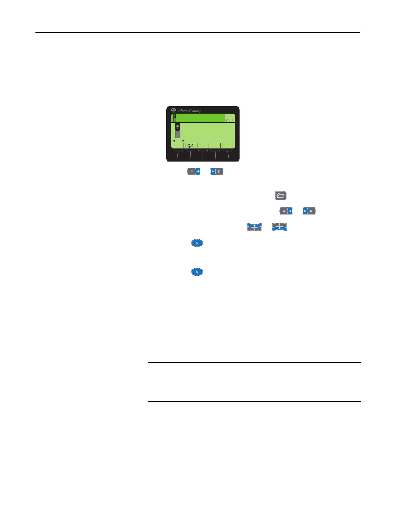
46 Rockwell Automation Publication 750COM-UM009A-EN-P - May 2017
Chapter 2 Configure the Interface
Because the built-in EtherNet/IP interface is part of Port 0, restoring the port
defaults also resets other drive configuration settings that are made in Port 0.
Follow these steps to restore interface parameters to their default configuration
values.
1. Access the Status screen, which is displayed on HIM power-up.
2. Use the or key to scroll to Port 0, which is the drive port
contains the built-in EtherNet/IP interface.
3. display the last-viewed folder, select the key.
4. To scroll to the MEMORY folder, use the or key.
5. To select Set Defaults, use the or key.
6. Press the (Enter) key.
The Set Defaults popup box appears.
7. Press the (Enter) key again.
The warning popup box appears.
8. Reset parameters to their default configuration values by selecting the
appropriate option:
• To restore MOST parameters to default configurations, press the
MOST soft key.
• To restore ALL parameters, press the ALL soft key.
• To cancel, press the ESC soft key.
9. Reset the interface by cycling power to the drive or by using the Reset
Device function of the HIM, located in the DIAGNOSTIC folder for
the drive.
IMPORTANT When performing a Set Defaults, the drive can detect a conflict and then not
allow this function to occur. If a conflict happens, first resolve the conflict
and then repeat this Set Defaults procedure. Common reasons for a conflict
include a drive that is running or a controller in Run mode.
00
Stopped
0.00 Hz
AUTO
PowerFlex 755TR
240V Cycle
Rev. 1.001 Ser. A
ESC REF TEXT
F
PAR#

Rockwell Automation Publication 750COM-UM009A-EN-P - May 2017 47
Configure the Interface Chapter 2
Viewing the Interface Status
Using Parameters
The following parameters provide information about the status of the
interface. You can view these parameters at any time.
Updating the Interface
Firmware
The interface firmware is contained within the PowerFlex 755T drive
firmware. The interface firmware can be updated over the network.
When updating firmware over the network, you can use the Allen-Bradley®
ControlFLASH™ software tool.
To obtain a firmware update for this interface, go to
http://compatibility.rockwellautomation.com/Pages/home.aspx
. This website
contains all firmware update files and associated Release Notes that describe
the following items:
• Firmware update enhancements and anomalies
• How to determine the existing firmware revision
• How to update the firmware using ControlFLASH software
Table 3 - Interface Status Parameters
Interface Parameter Description
0:356 - [DLs From Net Act] The number of controller-to-drive datalinks that are included in the network I/O
connection (controller outputs).
0:357 - [DLs To Net Act] The number of drive-to-controller datalinks that are included in the network I/O
connection (controller inputs).
0:301 - [Net Addr Src] Displays the active source for the interface node address, subnet mask, and gateway
address.
‘Switches’ (0) – The address comes from the rotary switches on the main control board.
‘Parameters’ (1) – The addresses come from 0:302 [IP Addr Cfg 1]…313 [Gateway Cfg
4].
‘BOOTP’ (2) – The address comes from a BOOTP server on the network.
‘DHCP’ (3) – The address comes from a DHCP server on the network and could be a
Stratix switch.
0:315 - [Net Rate Act 1] The data rate/duplex used by the ENET1 network port on the interface.
0:317 - [Net Rate Act 2] The data rate/duplex used by the ENET2 network port on the interface.

48 Rockwell Automation Publication 750COM-UM009A-EN-P - May 2017
Chapter 2 Configure the Interface
Notes:

Rockwell Automation Publication 750COM-UM009A-EN-P - May 2017 49
Chapter 3
Configuring the Drive in a Logix System
This chapter provides instructions on how to configure an Allen-Bradley®
ControlLogix® controller to communicate with a connected PowerFlex® 755T
drive. The minimum RSLogix 5000® or Studio 5000® software version that can
work with the PowerFlex 755T drives is version 20.
Topic Page
Establish Communication 48
Uploading the Electronic Data Sheet (EDS) File 50
Obtain Add-on Profiles 51
Create Logix Controller Project 51
Example Network 51
Adding the Bridge to the I/O Configuration 52
Add the Drive to the Project 54
Configure Input and Output Data 57
Download the Configuration to the Controller 60
Correlate the Drive with the Controller 62
Updating the AOPs and Database Files 63
Configuration to Aid in Field-Failure Replacement 65
Using an Ethernet Switch with DHCP/BOOTP Server 66
Using Firmware Supervisor 67
Using Automatic Device Configuration (ADC) 69
Configure a PowerFlex 755T Drive for ADC 71
ADC and Logix Memory 74
Peripheral Changes When Using ADC 74
Special Considerations For 20-750-S1 Safe Speed Module (S1) 75
Testing ADC 77
Monitoring ADC Progress 77
Programmatically Monitoring Connection Status and the ADC Configuration
Signature
80
Best Practices 82
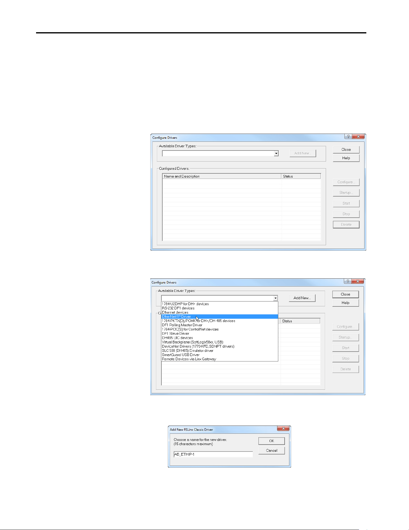
50 Rockwell Automation Publication 750COM-UM009A-EN-P - May 2017
Chapter 3 Configuring the Drive in a Logix System
Establish Communication
RSLinx® Classic software, in all its variations (Lite, Gateway, OEM, and so
forth), is used to provide a communication link between the computer,
network, and controller. RSLinx Classic software requires its network-specific
driver to be configured before communication is established with network
devices. To configure the RSLinx® Classic Driver, follow this procedure.
1. Start RSLinx Classic software.
2. From the communication menu, choose Configure Drivers to display
the Configure Drivers dialog box.
3. From the Available Driver Types pull-down menu, choose EtherNet/IP
Driver.
4. Click Add New to display the Add New RSLinx Classic Driver dialog
box.
5. Use the default name or type a name.
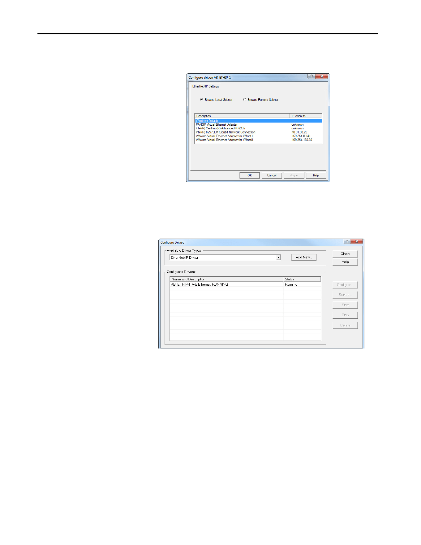
Rockwell Automation Publication 750COM-UM009A-EN-P - May 2017 51
Configuring the Drive in a Logix System Chapter 3
6. Click OK.
The ‘Configure Driver:’ dialog box appears.
7. Depending on your application, select either the browse local or remote
subnet option.
8. Click OK.
The Configure Drivers dialog box reappears with the new driver in the
Configured Drivers list.
9. Click Close to close the Configure Drivers dialog box.
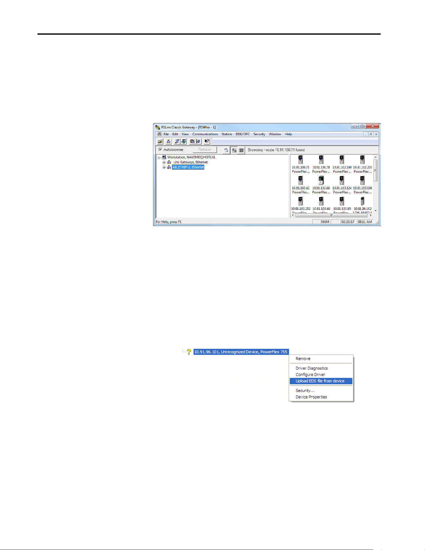
52 Rockwell Automation Publication 750COM-UM009A-EN-P - May 2017
Chapter 3 Configuring the Drive in a Logix System
10. Keep running RSLinx software and verify that the computer connects
with the drive.
a. From the Communication menu, choose RSWho.
b. In the menu tree, click the ‘+’ next to the Ethernet driver.
If the ‘EtherNet/IP Driver’ cannot see your drive, as an alternative, use
either the ‘Ethernet devices’ or the ‘Remote Devices via Linx Gateway’
RSLinx driver.
Uploading the Electronic
Data Sheet (EDS) File
PowerFlex 755T Series drives have built-in EDS files for RSLinx software to
upload and register.
1. Right-click the EtherNet/IP drive that is shown as a yellow question
mark or ‘Unrecognized Device’ in the RSWho dialog box.
2. Choose ‘Upload EDS file from device’ as shown in the following
example.
By uploading the EDS file, it also uploads the icon files for the device.
The question mark changes to a drive icon.

Rockwell Automation Publication 750COM-UM009A-EN-P - May 2017 53
Configuring the Drive in a Logix System Chapter 3
Obtain Add-on Profiles
When a new drive is used, or to benefit from new updates for Add-on Profiles
(AOP), you need the newest Add-on Profile update. Drive Add-on Profiles can
be updated anytime, and contain the latest database files available at the time of
release.
Go to http://compatibility.rockwellautomation.com/Pages/home.aspx
to
download the latest drive Add-on Profile for the PowerFlex 755T drive. The
Logix Designer application drive Add-on Profiles provide these advantages:
• Profiles for specific drives that provide descriptive controller tags for
basic control I/O words (logic command/status and reference/
feedback) and datalinks. Additionally, datalinks automatically take
the name of the drive parameter to which they are assigned. All Tags
are of the proper data type so there is no need for manual conversion
in the user program. These profiles substantially reduce I/O
mismatch errors and drive configuration time.
• The drive tab removes the need for a separate drive-software-
configuration tool. All drive configuration can be done within the
AOP.
• Drive configuration settings are saved as part of the controller project
file (.ACD) and also downloaded to the controller.
• Automatic Device Configuration (drive Add-on Profiles version
1.xxx or later, controller software version 20 or later).
Create Logix Controller
Project
The example in this section is for a ControlLogix® controller, revision 20 or
later, and the PowerFlex 755T drives, firmware 1.xxx or later. The minimum
RSLogix 5000 or Studio 5000 environment version that supports the
PowerFlex 755T drives is version 20.
Example Network
This section provides the steps to configure a simple EtherNet/IP network (see
Figure 9
). In our example, we configure a 1756-EN2T bridge to communicate
with a drive by using logic command/status, reference/feedback, and 32
datalinks (16 to read and 16 to write) over the network.
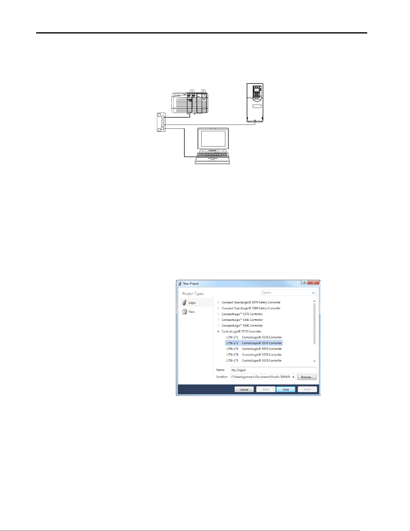
54 Rockwell Automation Publication 750COM-UM009A-EN-P - May 2017
Chapter 3 Configuring the Drive in a Logix System
Figure 9 - Example ControlLogix Controller EtherNet/IP Network
Adding the Bridge to the I/O Configuration
To establish communication between the controller and interface over the
network, you must first add the ControlLogix controller and its bridge to the
I/O configuration.
1. Start Studio 5000 Logix Designer® application software.
2. From the File menu, choose New to display the New Controller dialog
box. Select the desired controller, give your project a Name, and click
Next.
Select the Revision, Chassis used, and Slot location for the controller.
Edit Security and Redundancy if desired. Click Finish.
IP address 10.91.166.96
ControlLogix Controller
IP address 10.91.166.21
PowerFlex 755T drive with built-
in EtherNet/IP interface
Computer with
Ethernet Connection
Ethernet
Switch
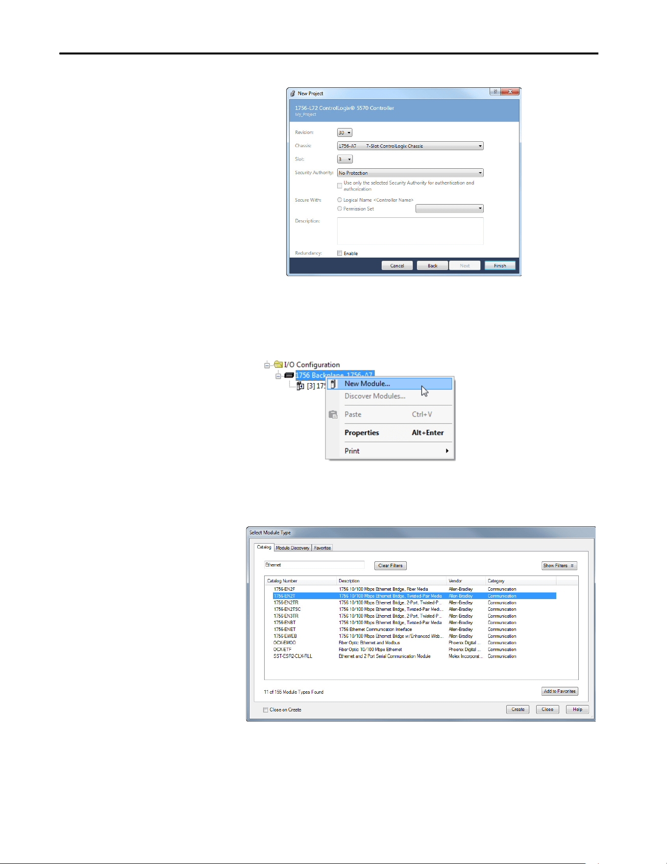
Rockwell Automation Publication 750COM-UM009A-EN-P - May 2017 55
Configuring the Drive in a Logix System Chapter 3
The Logix Designer application dialog box reappears with the tree
view in the left pane.
3. In the tree view, right-click the 1756 Backplane in the I/O
Configuration folder and choose New Module.
The Select Module Type dialog box appears.
4. To filter the displayed devices, enter the word Ethernet into the Search
field.
5. In the list, select the EtherNet/IP bridge that is used by your controller.
In this example, we are using a 1756-EN2T.
6. Click Create.
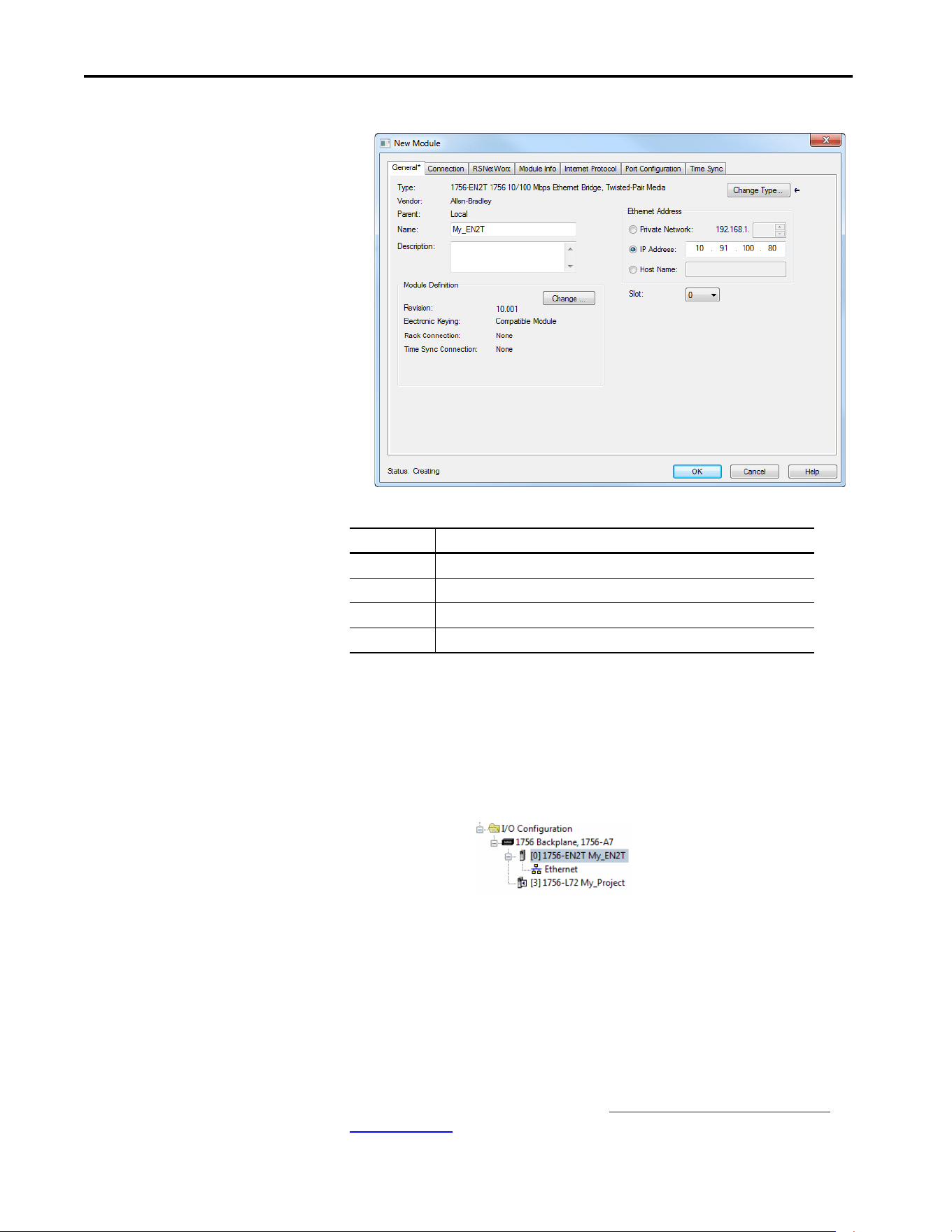
56 Rockwell Automation Publication 750COM-UM009A-EN-P - May 2017
Chapter 3 Configuring the Drive in a Logix System
The New Module dialog box for the bridge appears.
7. Edit the following:
Click Change if you to edit the Revision, Electronic Keying, or other
features.
8. Click OK.
The bridge is now configured for the EtherNet/IP network, added to
the Logix Designer application project, and appears in the I/O
Configuration folder.
In our example, a 1756-EN2T bridge appears under the I/O
Configuration folder with its assigned name.
9. Click Close to close the Select Module Type window.
Add the Drive to the Project
To transmit data between the controller and the drive, you must add the drive
as a child device to the parent Ethernet bridge. In this example, Studio 5000
Logix Designer application software version 30 is used with PowerFlex 755T
Add-on Profile version 1.01. See section Updating the AOPs and Database
Files on page 63 to determine which AOP version you are currently using.
Box Setting
Name A name to identify the bridge.
Description Optional – description of the bridge.
Ethernet Address The address to use for the Ethernet bridge.
Slot The slot location in the chases where the Ethernet bridge resides.
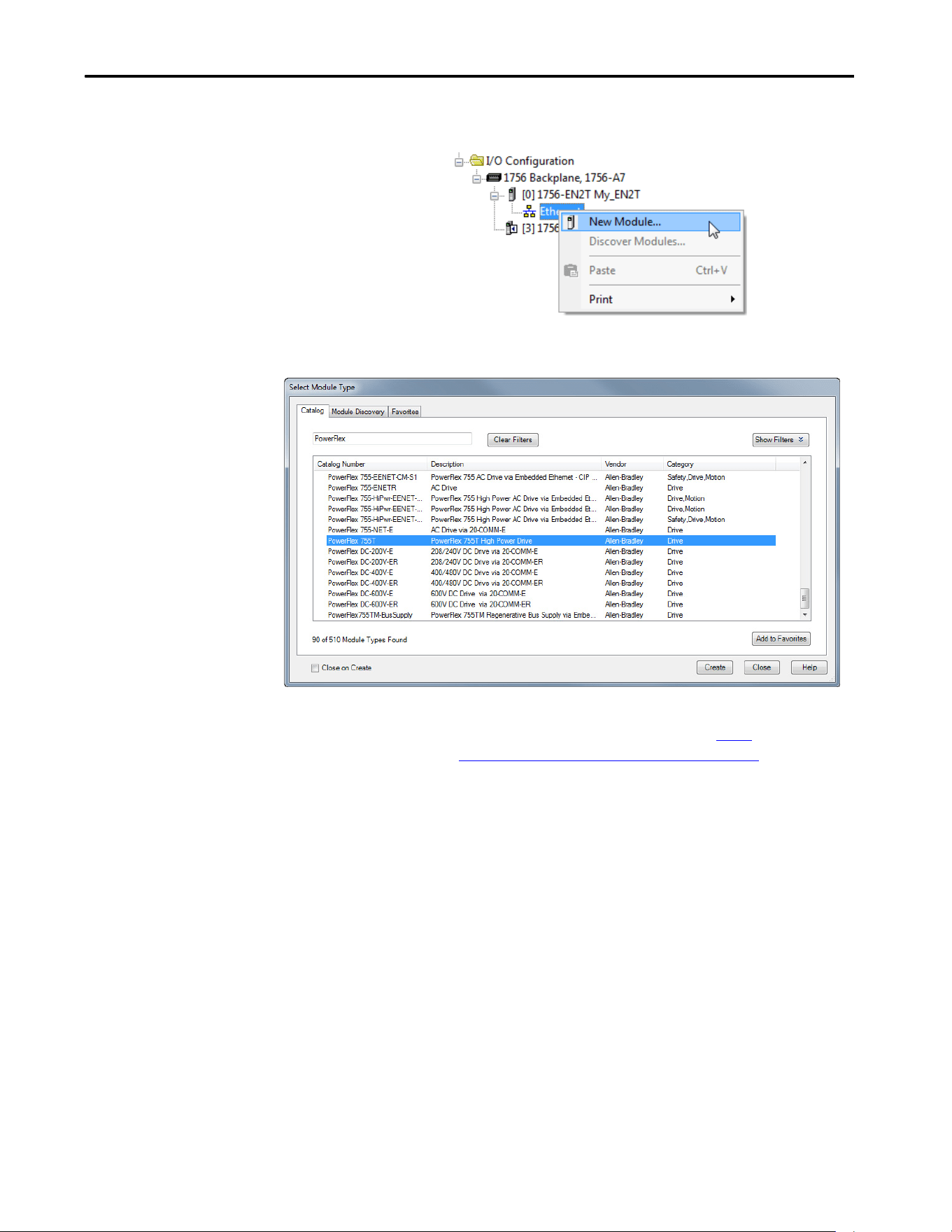
Rockwell Automation Publication 750COM-UM009A-EN-P - May 2017 57
Configuring the Drive in a Logix System Chapter 3
1. In the tree view, right-click the Ethernet network under the Ethernet
bridge and choose New Module to display the Select Module dialog box.
Enter ‘PowerFlex’ in the Search field to display the available PowerFlex
drives.
2. From the list, select the PowerFlex 755T drive.
3. Click Create.
After you click Create, the dialogue box may appear. If the drive is on
the network, select Create Database from Device. If the drive is not
on the network, select Update database from website. The link takes
you to the Rockwell Automation Download website to download the
750 Series Connected Components Workbench™ software database
files.
TIP If the desired PowerFlex drive is not shown, go to http://
compatibility.rockwellautomation.com/Pages/home.aspx and
download the latest PowerFlex 755T Add-on Profile.
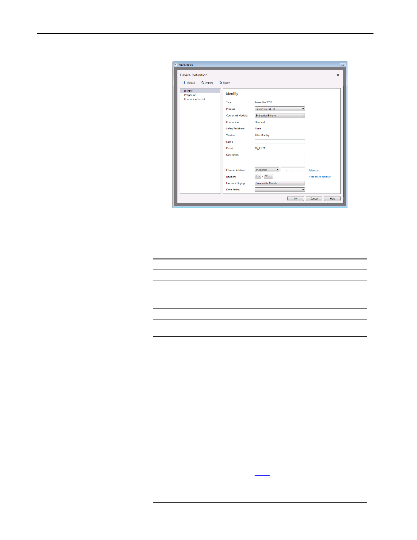
58 Rockwell Automation Publication 750COM-UM009A-EN-P - May 2017
Chapter 3 Configuring the Drive in a Logix System
The Device Definition window for the drive appears.
4. On the Identity window, edit the following data about the drive.
TIP If a drive has been replaced and programmed, do an upload on the
Device Definition window to update any inconsistencies on the
Device Definition window.
Box Setting
Product Select the type of PowerFlex 755T used.
Connected
Module
Select the Ethernet connection that is used by the drive.
Name A name to identify the drive.
Description Optional – description of the drive.
Ethernet
Address
The IP address of the drive. Click the Advanced link if Network Address Translation (NAT) is
used.
Revision The major and minor revision of the firmware in the drive. If the desired major and minor
revision for the drive is not listed, the drive database is not installed on your computer. To get
the correct database revision, click the ‘Need more options?’ link to:
Create Database Device: Creates a database from an online network drive.
– To locate the desired drive, navigate the RSLinx software RSWho dialog box.
– Select the desired drive, and click OK. Data is uploaded from the drive to create the
database on the computer.
– Close the Module Definition dialog box and then reopen it to display the new revision.
Update Database from website: When a drive is not available online, do the following.
– Automatically opens the Product Compatibility and Download Center website with the
necessary database install file listed.
– Download the file.
– Close the Module Definition dialog box.
– Reopen it to display the new revision.
Electronic
Keying
Compatible Module is recommended when Firmware Supervisor is not used to update a
replacement of this drive. The ‘Compatible Module’ setting for Electronic Keying verifies that
the physical module is consistent with the software configuration before the controller and
bridge make a connection. Make sure to set the correct revision in this dialog box. See the
online Help for additional information on this and other Electronic Keying settings.
When using Firmware Supervisor to store firmware for the drive, always choose ‘Exact Match’.
When using ADC, see the table on page 73
for more details.
Drive Rating The voltage and current rating of the drive. If the drive rating is not listed, the drive database
is not installed on your computer. For information on how to get a drive database, select
‘Need More Options?’ described in the Revision section of this table.
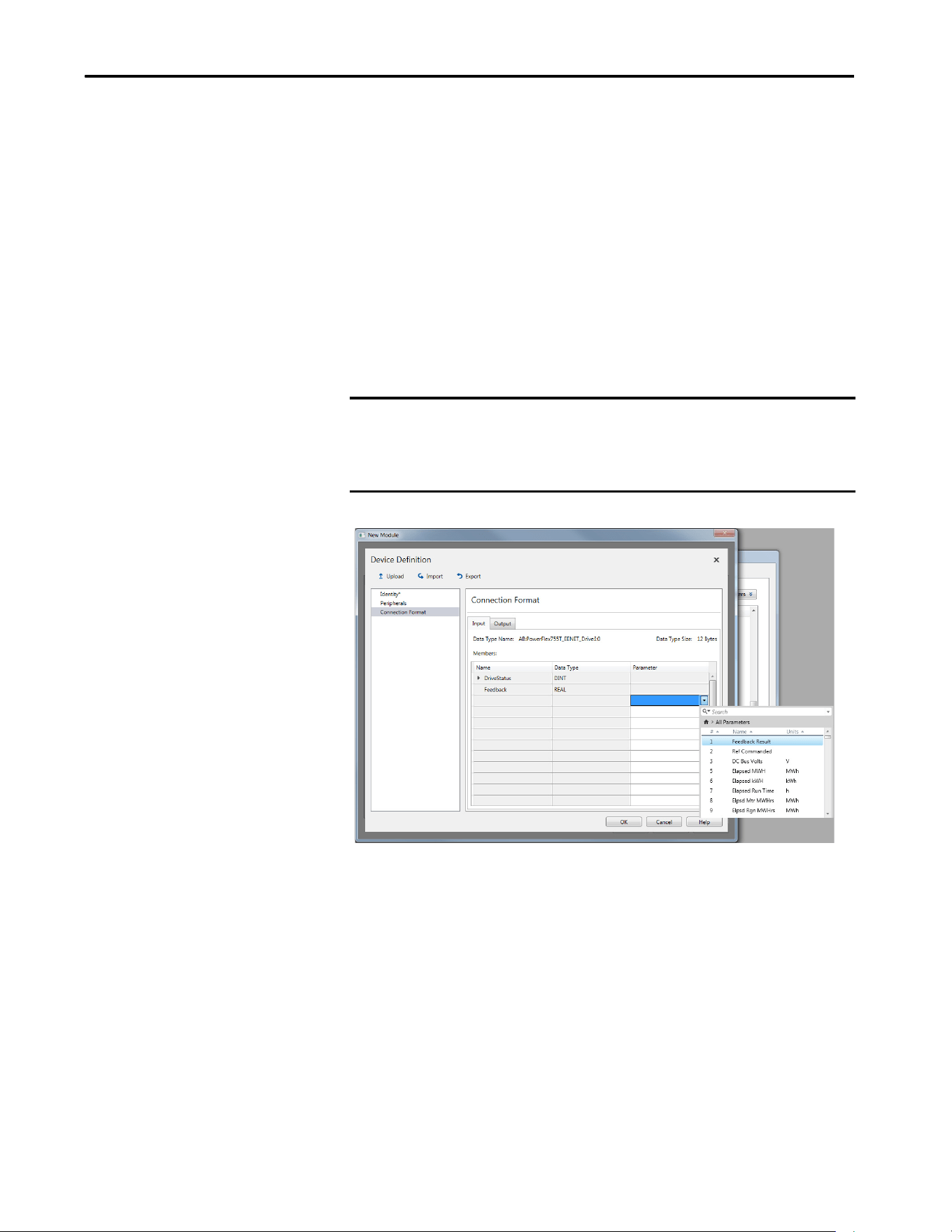
Rockwell Automation Publication 750COM-UM009A-EN-P - May 2017 59
Configuring the Drive in a Logix System Chapter 3
Configure Input and Output Data
Logic status, feedback, logic command, and reference words are automatically
configured by default and are always transmitted.
1. Select Connection Format to display the Input and Output tables that
are used to select the I/O communicated between the controller and
drive via datalinks.
The Input tab contains inputs to the controller from the drive and the
Output tab contains outputs from the controller to the drive. Up to 16
datalink inputs and 16 datalink outputs can be configured for a
PowerFlex 755T drive.
2. Start in the first editable field in the Parameter column on the Input tab.
Use the pull-down menu and open the parameter window to select the
desired parameter for datalink.
3. Repeat for any additional datalinks.
IMPORTANT Always use the datalink parameters in consecutive numerical order by
starting with the first parameter. Otherwise, the network I/O connection is
larger than necessary, which needlessly increases response time and
memory usage.
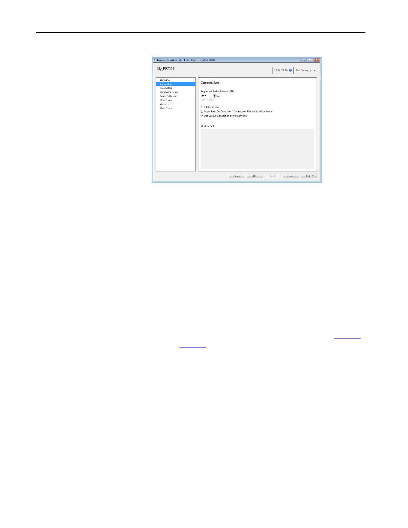
60 Rockwell Automation Publication 750COM-UM009A-EN-P - May 2017
Chapter 3 Configuring the Drive in a Logix System
4. Repeat for the Output tab and select the desired parameters to datalink.
5. In the Requested Packet Interval (RPI) box, set the RPI to the desired
value (default is 20.0 milliseconds).
This value determines the interval that a controller uses to move data to
and from the drive. To conserve bandwidth, use higher values for
communicating with low priority devices.
The ‘Inhibit Module’ box, when checked, inhibits the controller from
communicating with the drive. When the ‘Major Fault On’ box is
checked, a major controller fault occurs when the connection to the
drive fails while the controller is in the Run mode.
Unicast reduces network traffic and is recommended whenever possible.
6. Click OK.
The new node now appears under the bridge in the I/O Configuration
folder. If you double-click the Controller Tags, you see that module-
defined data types and tags have been automatically created (Figure 10
and Figure 11
).
All tag names are defined and datalinks include the assigned drive
parameter name. After you save and download the configuration, these
tags allow you to access the Input and Output data of the drive via the
ladder logic of the controller.
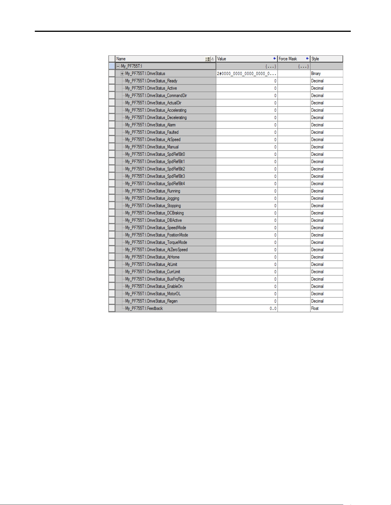
Rockwell Automation Publication 750COM-UM009A-EN-P - May 2017 61
Configuring the Drive in a Logix System Chapter 3
Figure 10 - Controller Input Tags Example
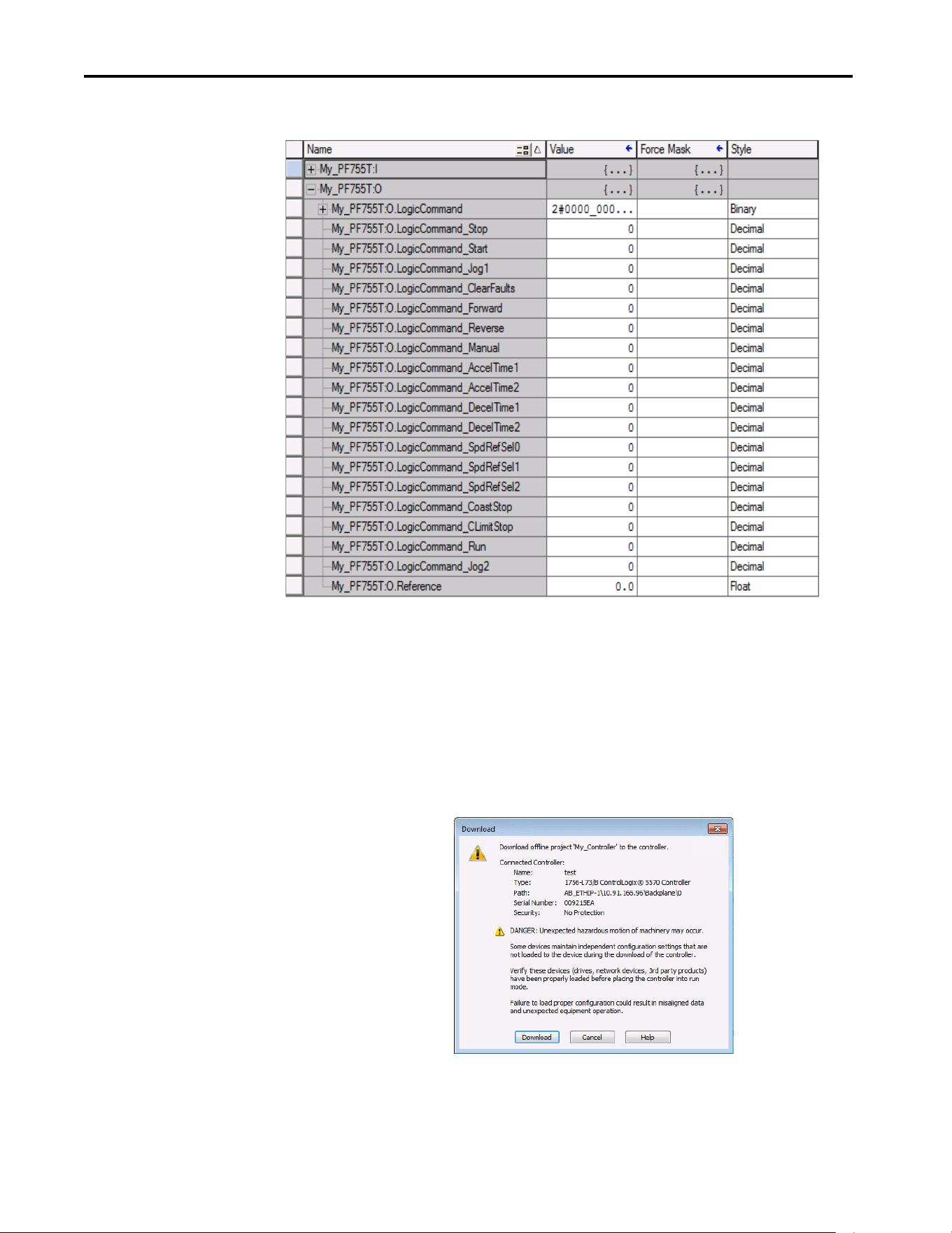
62 Rockwell Automation Publication 750COM-UM009A-EN-P - May 2017
Chapter 3 Configuring the Drive in a Logix System
Figure 11 - Controller Output Tags Example
Download the Configuration
to the Controller
After adding the bridge and drive to the I/O configuration, download the
configuration to the controller. Save the project on your computer.
1. Save the Project on your computer.
2. From the Communication menu in the Logix Designer application
dialog box, choose Download.
The Download dialog box appears.

Rockwell Automation Publication 750COM-UM009A-EN-P - May 2017 63
Configuring the Drive in a Logix System Chapter 3
3. Click Download to download the configuration to the controller.
When the download is successfully completed, Logix Designer
application software goes into the Online mode.
If the controller was in Run mode before Download was clicked, Logix
Designer application software prompts you to change the Controller
mode back to Remote Run. In this case, choose the appropriate mode of
operation for your application.
If the controller was in Program mode before Download was clicked,
this prompt does not appear.
4. From the File menu, choose Save.
The first time a project is saved, the Save As dialog box appears.
a. Navigate to a folder.
b. Type a file name.
c. Click Save to save the configuration as a file on your computer.
To verify that present project configuration values are saved, Logix
Designer application software prompts you to upload them.
5. Click Yes to upload and save the values.
TIP If a message box reports that Logix Designer application software is unable
to go online: Find your controller in the Who Active dialog box.
From the Communication menu, choose Who Active.
Find and select the controller.
Click Set Project Path to establish the path.
If your controller does not appear, add or configure the EtherNet/IP driver
with RSLinx software. See Establish Communication on page 48
and RSLinx
online help for details.
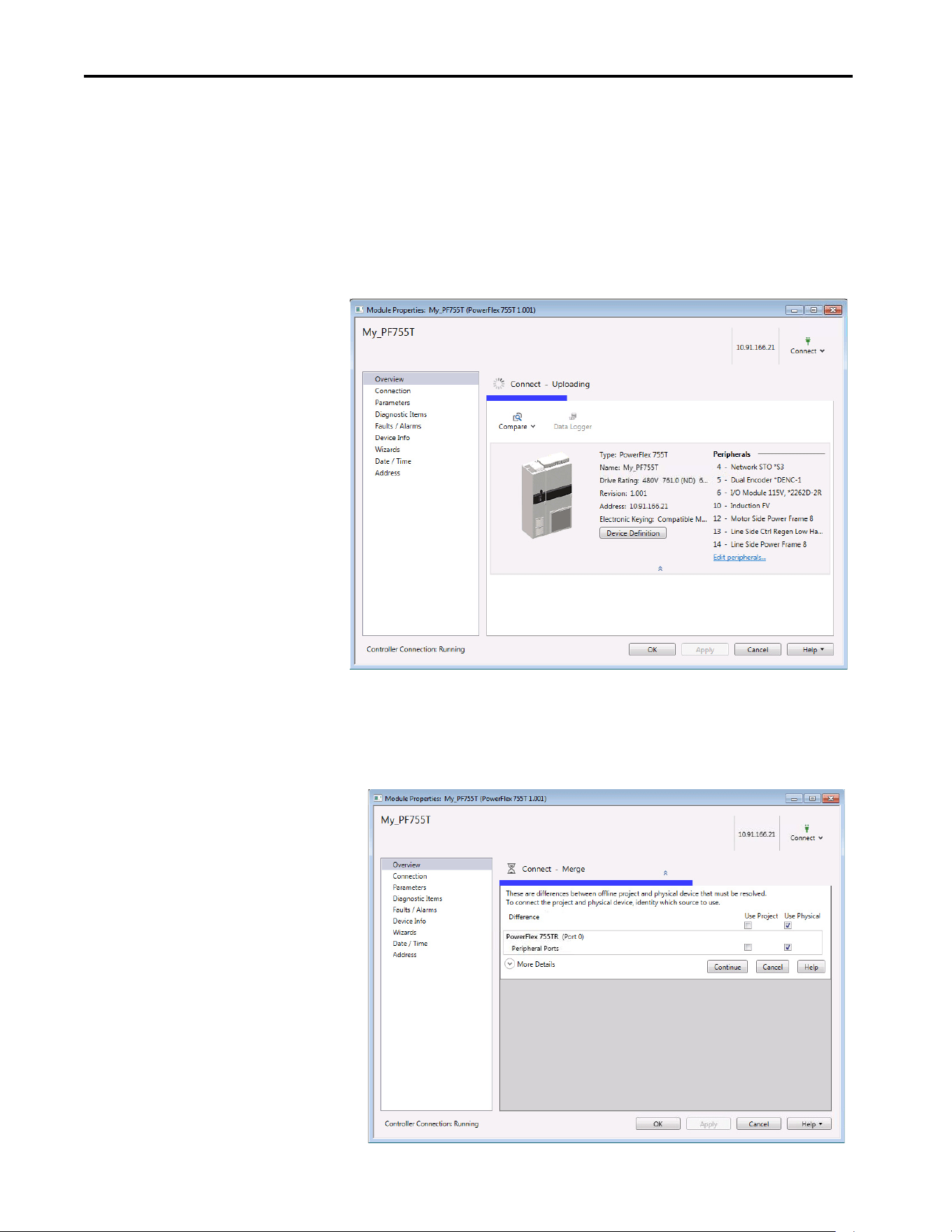
64 Rockwell Automation Publication 750COM-UM009A-EN-P - May 2017
Chapter 3 Configuring the Drive in a Logix System
Correlate the Drive with the Controller
Correlate the drive settings to the Logix Designer application project I/O
settings so that they match. While online with the controller:
1. In the tree view under I/O Configuration, right-click the drive and
choose Properties.
2. The drive profile opens and immediately begins to correlate.
3. If the Differences Found dialog box appears (which is typical), click
Download. The project settings are downloaded from the controller to
the drive and its connected option module.
If Upload is clicked, the drive and option module settings are uploaded
to the controller.
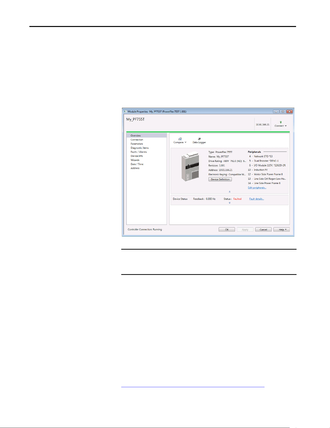
Rockwell Automation Publication 750COM-UM009A-EN-P - May 2017 65
Configuring the Drive in a Logix System Chapter 3
4. Correlation is performed so the configuration in the project matches the
configuration in the physical drive. If differences are found, you need to
select either ‘Use Project’ or ‘Use Physical’ for each identified item.
Check the boxes for your specific needs. To show additional information
about the differences, select the More Details pull-down menu.
5. Click Continue.
After a few moments, the Module Properties dialog box will use a green
bar to indicate that it is connected to the drive.
6. Click OK to close the Module Properties dialog box for the drive.
Updating the AOPs and
Database Files
Each version of the RSLogix 5000 / Studio 5000 application ships with the
latest versions of available AOPs. However, new drives (new AOPs), updates
(software enhancements and anomaly fixes), and device database files that are
required for new firmware releases can occur at any time. If you are missing any
of the following, you can obtain the AOP and database updates via free
download at the Product Compatibility and Download Center (PCDC):
• An AOP for a specific drive
• A specific feature, such as ADC
• A desired firmware revision in an existing AOP
http://compatibility.rockwellautomation.com/Pages/home.aspx
IMPORTANT The I/O OK box in the upper left of the Logix Designer application dialog box
must be steady green. There must not be a yellow warning symbol in the
tree view under the I/O Configuration folder next to the drive.
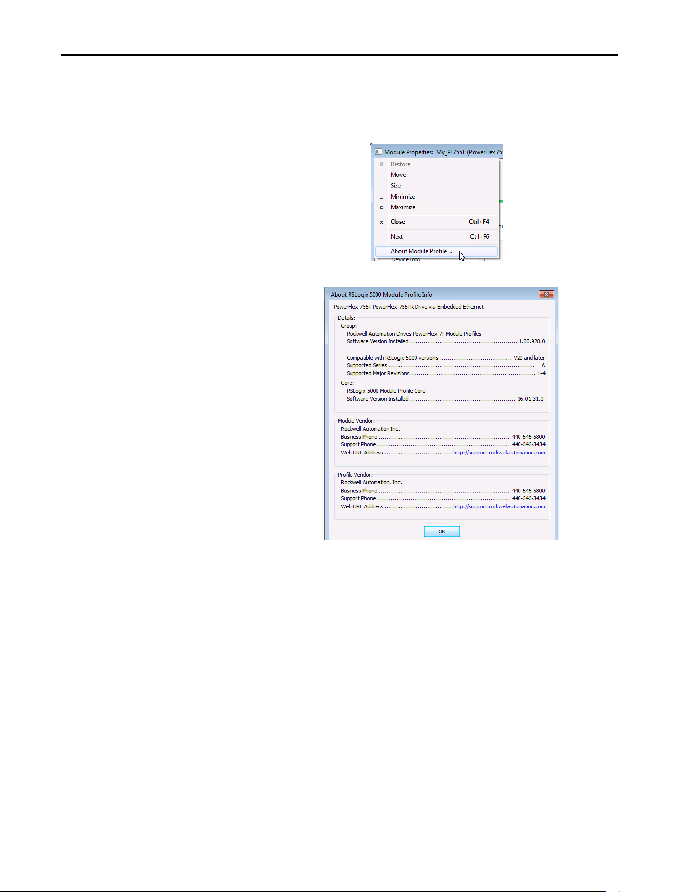
66 Rockwell Automation Publication 750COM-UM009A-EN-P - May 2017
Chapter 3 Configuring the Drive in a Logix System
To determine your AOP version:
1. Left-click on Module Properties icon in the upper left-hand corner of
the AOP.
2. Display the AOP version by selecting About Module Profile.
The drive AOPs are shipped with the latest drive and peripheral database files.
However, new firmware revisions can be released at any time. All available
firmware revisions for a drive are displayed in the Revision field in the Module
Definition window. If you are missing a firmware revision, click the Need more
options? link in the Device Definition window.
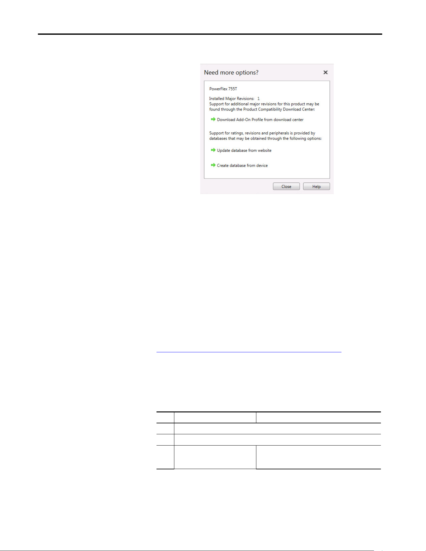
Rockwell Automation Publication 750COM-UM009A-EN-P - May 2017 67
Configuring the Drive in a Logix System Chapter 3
Figure 12 - AOP / Database Update Options
Two methods for updating database files for firmware revisions, one online and
one offline, are provided:
Create Database from Device – Opens the Identifying Device window to
navigate to any drive on the network. This includes a drive type that is different
than the AOP that you are currently using. The AOP automatically creates a
database for the selected device (must be a supported device).
Update Database from Website – Opens a web browser for offline downloads
from the product comparability download center (PCDC). Use the Product
Search to either search for ‘database’ or search for drive (for example
‘PowerFlex 755T’) and select the desired firmware revision.
To access database files, visit the web address:
http://compatibility.rockwellautomation.com/Pages/home.aspx
Configuration to Aid in Field-
Failure Replacement
Historically, field-failure replacement has been a manually intensive process.
Downtime can be minimized by automating some of the steps in the
replacement process:
Step Manual Process Automatic Process
1 Remove failed drive.
2 Mount and wire replacement drive.
3 Manually set IP address setting on drive
so it appears on network.
BOOTP server in Ethernet switch automatically assigns the IP
address. Drive is DHCP enabled by default and accepts
assigned IP address.
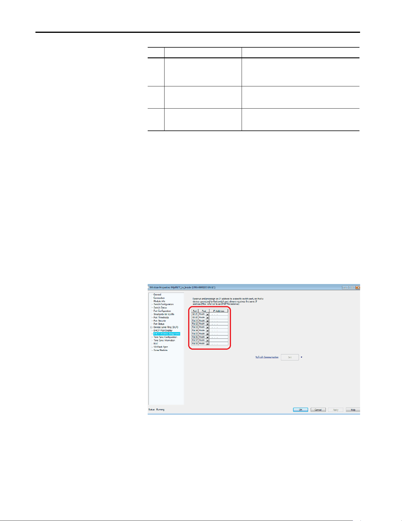
68 Rockwell Automation Publication 750COM-UM009A-EN-P - May 2017
Chapter 3 Configuring the Drive in a Logix System
Automatic IP address assignment in the Ethernet switch, Firmware Supervisor,
and ADC are mutually exclusive and can be used with or without each other. If
Firmware Supervisor and ADC are both enabled, Firmware Supervisor
executes first and must successfully complete before ADC executes.
Using an Ethernet Switch
with DHCP/BOOTP Server
To determine if a BOOTP server feature is supported, see the respective
Stratix® switch or third-party switch user manual (Note: Switches with DHCP
servers typically provide BOOTP server function too). The following Stratix®
switches also provide BOOTP server support:
Stratix 5700 (1783-EMS…)
The Stratix 5700 performs Dynamic IP address Assignment by
Port per the DHCP Address Assignment page.
4 Manually update drive with
ControlFLASH™ if necessary.
Electronic Keying between Logix controller and drive must
resolve successfully. Configure Firmware Supervisor and use
‘Exact Match’ for Electronic Keying to automatically update the
drive / peripheral firmware if needed.
5 Manually connect with CCW. Locate
correct saved configuration file and
download to the drive.
ADC in the Logix controller automatically downloads the
configuration when there is a configuration signature
mismatch, such as replacing a failed drive with a new one.
6 *Applies to manual process only. After the drive has been programmed, pull-up the Device
Definition window in RSLogix 5000 / Studio 5000 and do an
upload.
Step Manual Process Automatic Process
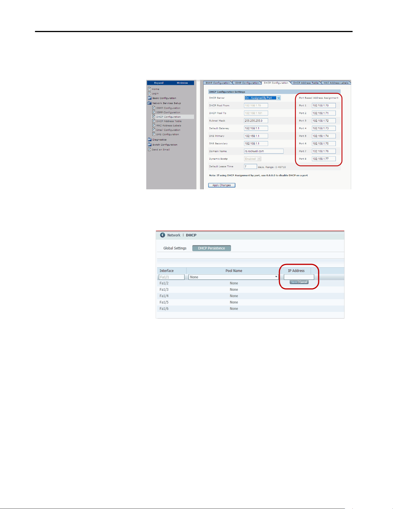
Rockwell Automation Publication 750COM-UM009A-EN-P - May 2017 69
Configuring the Drive in a Logix System Chapter 3
Stratix 6000 (1783-EMS…)
The Stratix 6000 performs ‘Dynamic IP address Assignment by Port’ per the
settings on the DHCP Configuration tab:
Stratix 8000 (1783-MS…) / 8300 (1783-RMS…)
The Stratix 8000/8300 sets the IP address per the ‘DHCP Persistence’ tab:
One IP address is configured for each port on the switch (star topology - one
drive per port). If you have a ring topology, the IP address for drive is set via
other means, such as the HIM or last octet rotary switches on the drive/
communication. Firmware Supervisor and/or ADC can still be used and will
execute after the drive gets its IP address and ‘appears’ on the network to the
Logix controller.
Using Firmware Supervisor
The Logix Firmware Supervisor function has been extended to provide
firmware updates for the peripherals that are connected to the drive. You must
be online and in Program mode with the controller to load/store the Firmware
Supervisor settings. To configure the controller to check and refresh the correct
firmware for the drive and peripherals, perform the following steps:
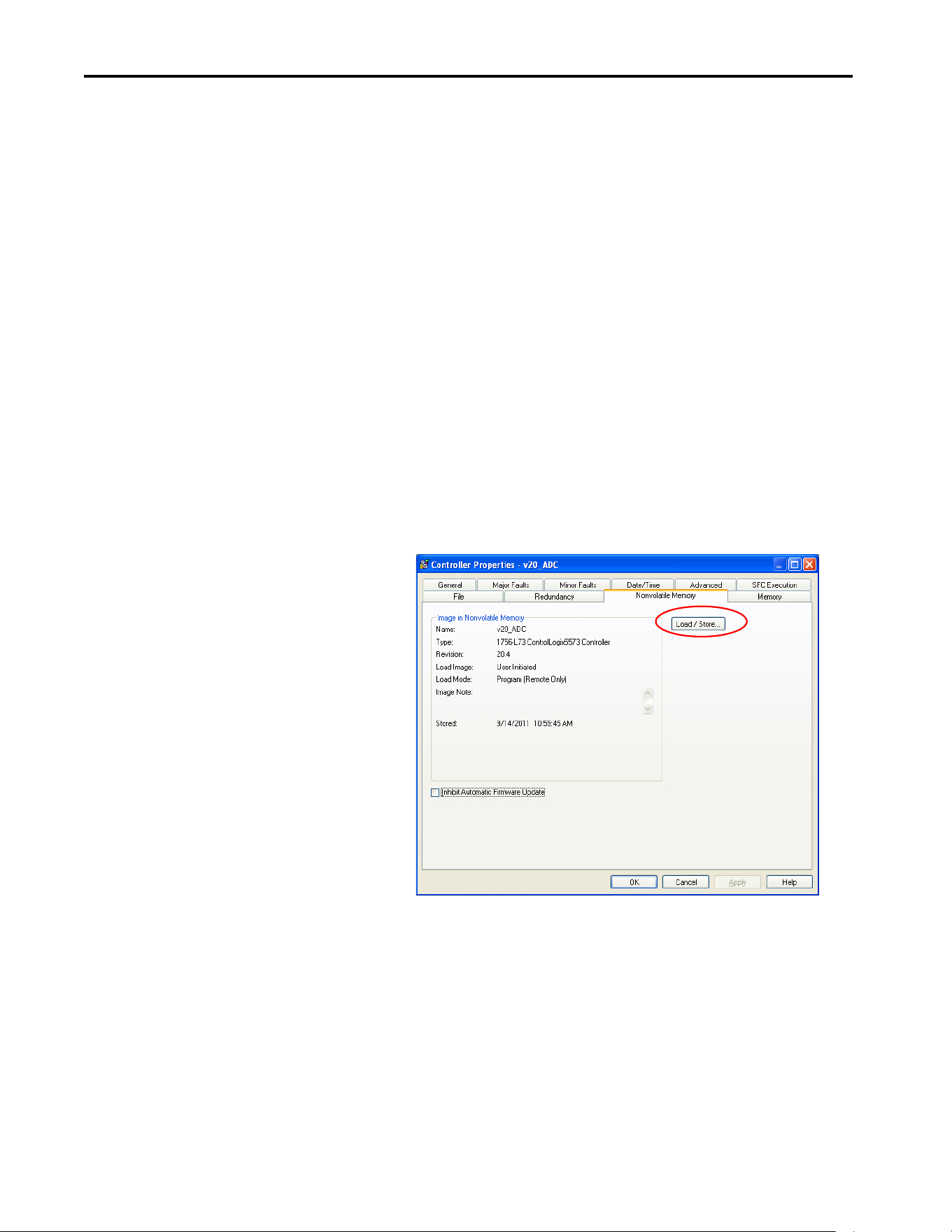
70 Rockwell Automation Publication 750COM-UM009A-EN-P - May 2017
Chapter 3 Configuring the Drive in a Logix System
1. Verify that ‘Exact Match’ keying is selected in the drive and peripherals’
properties dialog boxes.
a. View the drive keying by clicking the General tab.
b. Right-click each peripheral on the Drive tab.
c. View the keying of the peripheral by choosing Properties.
2. Verify that ControlFLASH firmware kits for each revision of firmware
for each device that must be stored in the controller is installed on the
computer that runs the programming software.
3. Verify that a CompactFlash or other storage card is installed in the
controller.
4. Use the programming software to go online with the controller in
Program mode.
5. Download your program if you have not done so already.
6. In the tree view, right-click the controller folder at the top of the
Controller Organizer.
7. Choose Properties.
8. On the Controller Properties dialog box, click the Nonvolatile Memory
tab.
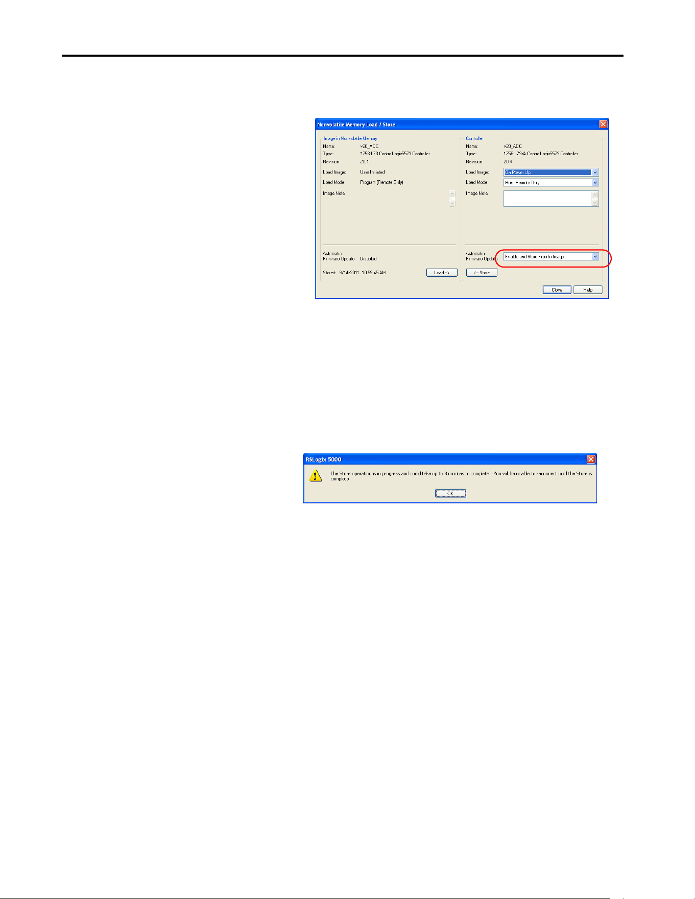
Rockwell Automation Publication 750COM-UM009A-EN-P - May 2017 71
Configuring the Drive in a Logix System Chapter 3
9. Click Load/Store.
The Nonvolatile Memory Load/Store dialog box appears.
10. From the Automatic Firmware Update pull-down menu, choose Enable
and Store Files to Image.
11. Click <-- Store.
Two confirmation dialog boxes open that relate to communication
disruptions and erasure of the current contents of the storage card.
12. If okay, click Yes on either dialog box.
The programming software goes to the Offline state, and this dialog
box appears.
13. Wait for the store operation to complete, and then attempt to go online
with the controller again.
Using Automatic Device
Configuration (ADC)
Automatic Device Configuration (ADC) is a Studio 5000 - Logix Designer
application feature that supports the automatic download of drive
configuration data. When the RSLogix 5000 software controller establishes an
I/O connection with a drive and its associated peripherals, it checks a
configuration signature for each port. This is to determine if an ADC
download is needed. The purpose is to reduce downtime in a field replacement
situation by automatically downloading the configuration rather than
manually with a separate tool.
ADC is available with the following software:
• Studio 5000 - Logix Designer, Version 21 or later
• RSLogix 5000, Version 20
• PowerFlex 755T AOPs, Version 1.xxx or later

72 Rockwell Automation Publication 750COM-UM009A-EN-P - May 2017
Chapter 3 Configuring the Drive in a Logix System
The latest drive AOPs ship with each release of Logix Designer and are also
available for free download at:
http://compatibility.rockwellautomation.com/Pages/home.aspx
ADC works with all versions of the PowerFlex 755T drives when the
Logix I/O connection is made through the embedded Ethernet port.
Firmware updates are available for free download at:
http://compatibility.rockwellautomation.com/Pages/home.aspx
If you do not have the minimum levels of software and hardware, the ADC
feature is not available (ADC icon is missing or appears dimmed).
Drive configuration settings are stored inside the ACD project file. With
ADC enabled, the Logix controller automatically downloads the configuration
settings for a particular drive port if it detects that there is a configuration
signature mismatch with a port.
A configuration signature is a globally unique ID number. The Logix
controller uses the number to perform a quick compare to determine if a
download is needed. If the signatures match, no download is needed. If an
option module or entire drive is replaced, the configuration signature for the
respective port does not match and a download occurs to the port.
TIP To identify the drive AOP version you are using, open the AOP, click the icon
in the upper left corner of the window and select “About Module Profile”.
ATTENTION: Logix holds the Master copy of the drive configuration.
When ADC is enabled, ADC is triggered any time the Logix controller detects
a configuration signature mismatch when establishing an EtherNet/IP
network I/O connection.
• The use of other configuration tools, such as a HIM or CCW software must be
minimized and restricted to monitor-only operation. Any configuration
changes made by these tools will cause a configuration signature mismatch
the next time the Logix controller connects to the device. ADC writes over
any configuration changes made by the other tools. Consider using the Write
Mask function (drive 0:230 - [Write Mask Cfg]). The function stops tools
that are connected to ports other than the built-in EtherNet/IP port in a
PowerFlex 755T drive from writing to the drive. Any drive configuration
changes must be made with the Add-on Profile (AOP).
• The use of Explicit Messaging to perform parameter writes in the Logix
program must be limited to RAM memory by setting the proper Attribute in
the MSG instruction. Any writes to parameter nonvolatile storage (NVS) will
clear the configuration signature and cause a mismatch the next time the
Logix controller connects to the device. This triggers ADC, which writes over
any configuration changes that were previously made.

Rockwell Automation Publication 750COM-UM009A-EN-P - May 2017 73
Configuring the Drive in a Logix System Chapter 3
Configure a PowerFlex 755T Drive for ADC
ADC is configured within the AOP Device Definition window of the
PowerFlex 755T drives.
1. Open the desired PowerFlex 755T drive in the Logix Designer I/O
Configuration folder and click the Device Definition button.
IMPORTANT ADC may execute the first time the Logix controller connects to the drive
after ADC has been enabled. The configuration signatures in the controller
and drive synchronize, and stops future ADC downloads from occurring
unless a configuration change is made or the drive / peripheral is replaced.
If a port has configuration parameters that require a reset to become active,
ADC will reset the drive after the respective port parameters are
downloaded.
IMPORTANT When ADC is enabled, it can be activated if the controller is in Run or
Program mode. Select ‘Inhibit Module’ when changes are made to the drive
to limit ADC from writing over your changes. ‘Inhibit Module’ is on the
Connection tab in the drive module profile.
IMPORTANT Use select Stratix switches to provide the dynamic IP address assignment by
port. This removes the need to manually enter the IP address, subnet mask,
and Gateway address before connecting a replacement drive to the Ethernet
network.
IMPORTANT ADC can work in tandem with the Firmware Supervisor. If the Firmware
Supervisor is configured and enabled for a drive (‘Exact Match’ keying must
be used), the drive/ peripheral firmware is automatically updated (if
necessary) before any ADC operation for that port.
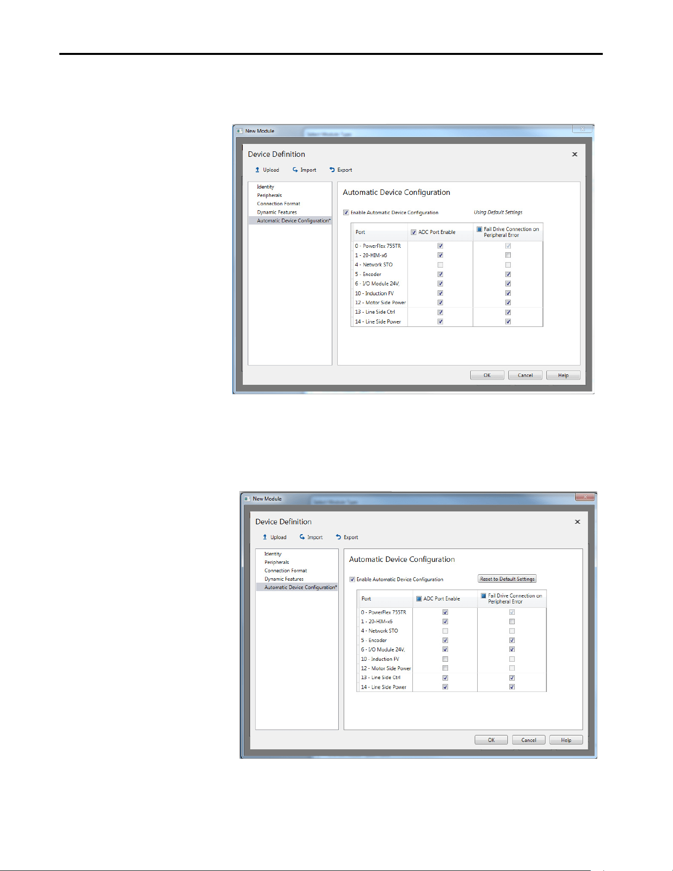
74 Rockwell Automation Publication 750COM-UM009A-EN-P - May 2017
Chapter 3 Configuring the Drive in a Logix System
2. Select Automatic Device Configuration in the navigation list. Check
the Enable Automatic Device Configuration box to enable ADC for the
drive. Default settings are automatically set for ADC.
3. ADC settings can also be adjusted at the port/peripheral level as desired
for your application. The Fail Drive Connection on Peripheral Error, if
selected, fails the network I/O connection with the Logix controller if
an error occurs with the respective port/peripheral. Make any needed
changes. If you make changes and want to revert to the default settings,
click the Reset to Default Settings button. Click OK when finished.
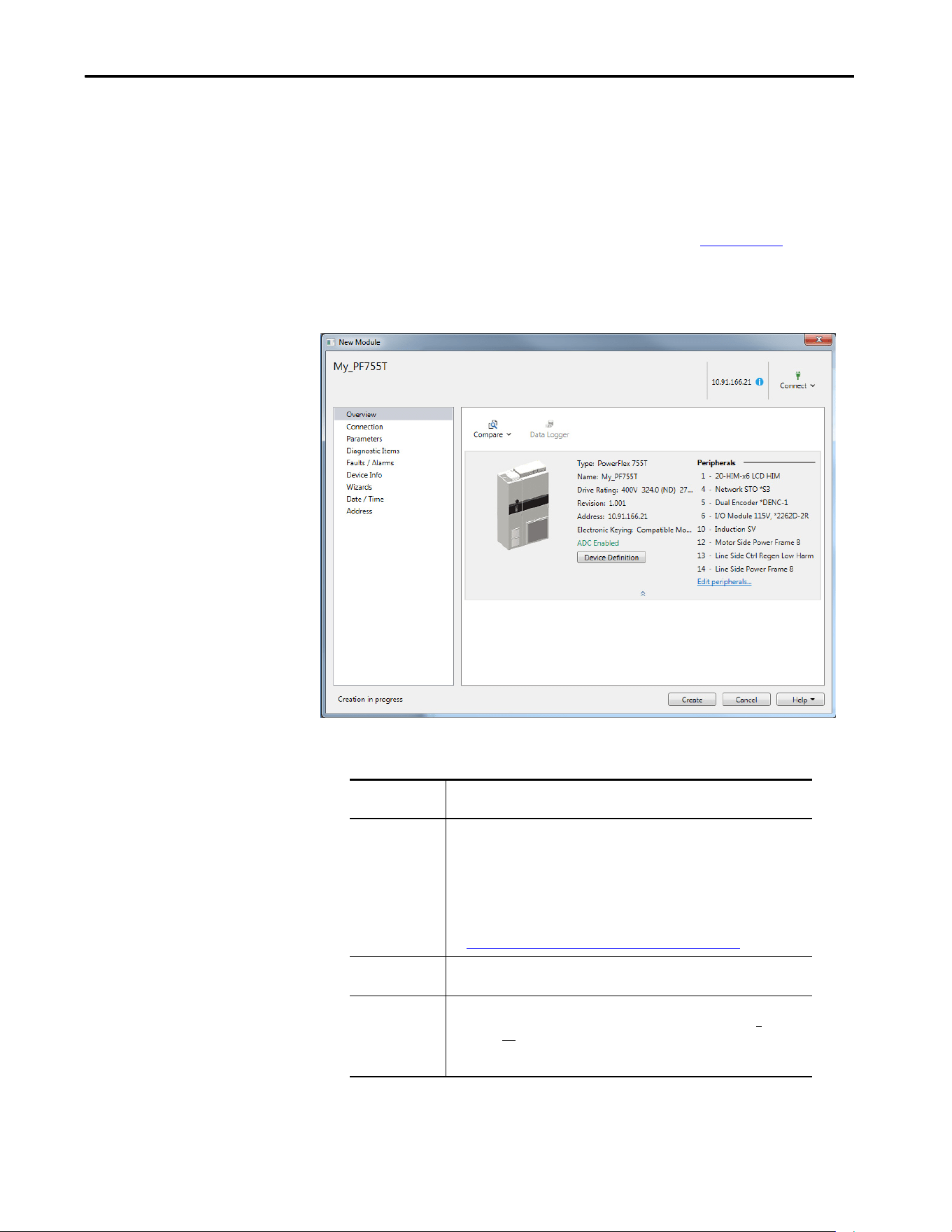
Rockwell Automation Publication 750COM-UM009A-EN-P - May 2017 75
Configuring the Drive in a Logix System Chapter 3
Some peripherals do not use ADC, and the 20-750-S3 Network STO
option module is one example. Its configuration is managed by the
Safety Controller is downloaded in the Safety Forward open
automatically when the safety connection is opened. Its checkboxes
appear dimmed to signify that ADC is not used with this module. For
more information on the S3 option module, see PowerFlex 755
Integrated Safety - Safe Torque Off, publication 750-UM004
.
Option Module
4. When ADC is enabled, the Overview page in the AOP lists ‘ADC
Enabled’. No text is displayed when ADC is not enabled.
Only two Electronic Keying selections are recommended when using
ADC:
It is also recommended that 0:230 [Write Mask] is set to write-protect all
other ports when ADC is used. When ADC is enabled, the Logix controller
Electronic Keying
Selection
Recommendation
Exact Match Use this selection only if:
• Your system design specification requires that a replacement drive/peripheral is
identical—down to the Minor revision of firmware (x.xxx).
• You are implementing Firmware Supervisor upgrade support and ADC.
ControlFLASH™ firmware kits for the revision of firmware that is used for each
drive/peripheral must be installed on the computer that runs the programming
software. Upgrade files can be downloaded from:
http://compatibility.rockwellautomation.com/Pages/home.aspx
Compatible Module This is the recommended setting to use for ADC when Firmware Supervisor is not
used.
Disable Keying When using ADC, this selection is not recommended. This selection allows a
replacement to have any different Device Type, Product Code, or Major (X
.xxx) and/
or Minor (X.xxx) firmware revision. It is up to the user to provide a replacement that
has a firmware revision greater than or equal to the original. If a replacement with
older firmware is used, the ADC download can fail.

76 Rockwell Automation Publication 750COM-UM009A-EN-P - May 2017
Chapter 3 Configuring the Drive in a Logix System
'owns' the configuration in the drive. Only make Configuration changes via the
Add-on Profile (AOP).
If a port is not write-protected, then a change that is made by another tool (for
example, a HIM at Port 1) clears the Configuration Signature for the
respective port. This causes ADC to trigger on the next network I/O
connection and overwrite the change with the configuration that was stored in
the controller.
The HIM and other software tools, such as Connected Components
Workbench, can continue to be used for purposes of monitoring.
ADC and Logix Memory
Start in RSLogix 5000 Designer application software, version 16 or later, drive
configuration settings are stored in the project ACD file that is downloaded
and stored in the controller. Configuration settings for ADC-capable devices
contain additional port and script information.
A typical PowerFlex drive consumes less than 25 kilobytes of Logix memory
per drive. Most Logix controllers have megabytes of memory available, so
memory typically is not an issue. You can monitor Logix memory usage in
RSLogix 5000 / Studio 5000 application via the Controller Properties
window.
Peripheral Changes When Using ADC
The PowerFlex 755T drives and bus supplies check the power peripherals
(power modules, LCL filters, precharge modules, and Torque Accuracy
Modules) every time it powers up. During power up, the system checks to see if
the peripherals are the same and in the same order. If the power peripherals are
replaced, or the order of the power peripherals changes, then the PowerFlex
755T detects the change. Changes to the following items trigger the need for
acknowledgment:
• Power peripheral added
• Power peripheral removed
•Power changed
• Backplane option peripheral removed
• Backplane option peripheral changed
ADC cannot operate until a user acknowledges the change, and the following
features are unavailable until the change is accepted:
• The Line Side Converter cannot be modulated.
• The Motor Side Inverter cannot be modulated.
• A command to reset cannot be accepted.
• A parameter download cannot be accepted.

Rockwell Automation Publication 750COM-UM009A-EN-P - May 2017 77
Configuring the Drive in a Logix System Chapter 3
The PowerFlex 755T indicates a configuration change in 0:90 [Cfg Status].
The configuration change must be manually accepted by entering a value of
'Accept' (1) in 0:91 [Cfg Acknowledge].
Follow the procedure to use ADC when servicing power peripherals:
1. Remove power from the system and de-energize the cabinet.
2. Disconnect the Ethernet cable.
3. Update the hardware configuration as needed, this includes replacing
and re-ordering power peripherals and making the needed fiber optic
connections.
4. Verify the updated hardware configuration for correctness and verify
that the power peripherals are properly secured and installed.
5. Verify that the fiber optic connections to the power peripherals are
correct.
6. Apply power.
7. Accept the configuration change by entering the value ‘Accept (1)’ as the
input for 0:91 [Cfg Acknowledge].
8. Remove power from the system and de-energize the cabinet. This could
be needed to gain safe access to the Ethernet port.
9. Connect the Ethernet cable.
10. Apply power.
11. If a 24V auxiliary power is used, power must be cycled on the drive for a
second time.
If the Ethernet cable is connected before the acknowledgment, ADC attempts
to download repeatedly, and fails repeatedly, until the acknowledgment is
accepted.
Special Considerations For 20-750-S1 Safe Speed Module (S1)
There are special considerations when using ADC with the 20-750-S1 safe
speed module. The discrete wired or hardwired advanced safety cards require
manual user intervention before the drive can become operational. ADC can
still be used, even though a manual step of the drive is required.
IMPORTANT After a power peripheral change is detected, the PowerFlex 755T does not
accept downloads from the controller until the configuration change is
accepted in 0:91 [Cfg Acknowledge].

78 Rockwell Automation Publication 750COM-UM009A-EN-P - May 2017
Chapter 3 Configuring the Drive in a Logix System
Along with the configuration of the Safe Speed Monitor (SSM), the password
for the module is stored in the configuration script in the controller. The
password is used as part of the connection process to allow the configuration
that is stored in the controller to be downloaded to the module. This password
must be entered into the profile for the 20-750-S1 module (S1) in the Module
Properties dialog box of the drive, in RSLogix 5000 / Studio 5000 application.
This password value is entered in Parameter 13 of the 20-750-S1 module (S1)
on controller download to the module. Record the parameter value for future
use when interacting with the module. Enter the password into
Parameter 1 for the 20-750-S1 module (S1) to allow either locking via
Parameter 5 or by changing the password via Parameter 13 and 17.
The following manual steps take an existing configured SSM out of Run mode
to allow the controller to download the configuration to the new SSM. For
example, during replacement of the drive and reuse of the existing module.
1. Inhibit the drive connection—or disconnect the communication card
through which the controller is trying to configure the 20-750-S1
module by using ADC.
2. Set SSM Parameter 1 [Password] to the current password of the
module.
3. Set the SSM Parameter 5 [Lock State] to ‘0’ (Unlock).
4. Set the SSM Parameter 6 [Operating Mode] to ‘0’ (Program).
5. If the SSM password is not ‘0’, change the password of the Module to ‘0’.
6. Set the SSM Parameter 1 [Password] to the current password of the
module.
IMPORTANT Firmware Supervisor cannot be used to update the 20-750-S1 module
firmware, due to unique upgrade components within its safety core. The
firmware can be manually upgraded using ControlFLASH, a 1203-USB Serial
Converter, and the appropriate upgrade file.
IMPORTANT Before you save the configuration to the controller, do not set the SSM
parameters in the Add-on Profile configuration:
• Parameter 5 [Lock State] to ‘1’ (Lock)
• Parameter 6 [Operating Mode] to ‘1’ (Run)
By setting these parameters, you lock the Module, stop writing the higher
numbered parameters, and cause the ADC download to fail. These two
parameters must be changed manually after performing an upload or after
the ADC download.
IMPORTANT Perform these manual steps when the Ethernet cable is disconnected from
the drive.The controller, while attempting to configure the S1 Module locks
out writes from other sources, such as the HIM.

Rockwell Automation Publication 750COM-UM009A-EN-P - May 2017 79
Configuring the Drive in a Logix System Chapter 3
7. Set the SSM Parameter 13 [New Password] to ‘0’.
8. Set the SSM Parameter 17 [Password Command] to ‘1’ (Change
PW).
9. Uninhibit the connection or reconnect the cable.
The controller can download the new configuration, including the new
password.
The following manual steps are required to put the safe speed monitor (S1)
into Run mode, generate a configuration signature, and lock the configuration.
To replace the (S1) Module with a new, out-of-the-box unit.
1. Set the safe module (S1) Parameter 6 [Operating Mode] to ‘1’ (Run).
A configuration signature is generated.
2. Access the safe module (S1) Parameter 10 [Signature ID] and record
the configuration signature value that is stored in this parameter.
3. Enter the current password for the safe module (S1) into parameter 1
[Password].
4. Set the safe module (S1) Parameter 5 [Lock State] to ‘1’ (Lock).
These steps can be performed with a HIM, drive software configuration tool,
or via an HMI that can trigger explicit message writes from the controller
program. To meet SIL CL3, PLe, or Cat 4 requirements, verify that the correct
configuration is locked in the safe speed monitor (S1). See the drive and safe
monitor (S1) documentation for more information.
Special Considerations for Communications and Option Developers
Kit Option Cards
There are special considerations when using ADC with communications
option cards or Options Developer Kit (ODK) cards. Communication option
cards include the following: 20-750-CNETC, 20-750-DNET, 20-750-
ENETR, 20-750-PBUS, 20-750-PNET, and 20-750-PNET2P. ODK cards
include the 20-750sc-8u from Spectrum Controls.
ADC can still be used, but these cards require a power cycle before the drive
can become operational.
Testing ADC
ADC can be tested by clearing the Configuration Signature in a drive port and
then either cycling power or by resetting the drive. Possible methods are:
IMPORTANT Before operating the drive or bus supply, perform a power cycle
after the ADC configuration download.

80 Rockwell Automation Publication 750COM-UM009A-EN-P - May 2017
Chapter 3 Configuring the Drive in a Logix System
Method 1
1. Connect via the Ethernet by using a second configuration tool, such as
Connected Component Workbench (CCW).
2. Change any unused parameters in the drive and/or peripheral ports.
Note the parameter value before and after your change. It is the initial
parameter write that causes the Configuration Signature to clear for a
particular port.
3. Reset the drive from the tool.
ADC triggers and executes.
4. Check the parameter that you changed to verify it has changed back to
the original setting.
Method 2
1. If a HIM is present and the port it resides in Port 1 is not write
protected, use the HIM to change any unused parameter in drive /
peripheral. It is the initial parameter write that causes the Configuration
Signature to clear for a particular port.
2. Reset (similar to step 3).
ADC triggers and executes.
3. Check the parameter that you changed to verify it has changed back to
the original setting.
Monitoring ADC Progress
The time that it takes for the Firmware Supervisor, ADC, and connection
process to complete varies from seconds to several minutes depending on
several factors.
• Whether Firmware Supervisor is enabled and must upgrade the drive
and/or any peripherals before ADC occurs. Updating drives or
peripherals add significantly to the connection process time and is
similar to the time it takes to update manually using ControlFLASH
software.
• The number of peripherals that are enabled for ADC.
• If a configuration signature, for the drive/peripheral, indicates that a
configuration download must be performed for the given port.
• If a 20-750-S1 option module, which requires a manual step in its
configuration process, is used.
• The number of drive resets required for ports with configuration
parameters require a reset to become active.

Rockwell Automation Publication 750COM-UM009A-EN-P - May 2017 81
Configuring the Drive in a Logix System Chapter 3
See the PowerFlex Drives with TotalFORCE™ Programming Manual,
publication 750-PM100 (or PowerFlex 755T Drive Status Indicator
Descriptions on page 116) for information about the status indicators. An
operational drive in a running Logix system has the following status indicator
states.
(1) If the HIM is present, it can display additional information.
Table 4 - Drive Status Indicators - Operational
Name Color State Description
STS
(Status)
Green Flashing Drive ready but not running, and no faults are present.
Steady Drive running, no faults are present.
Yellow /
Green
Flashing
Alternately
When running, a type 1 alarm exists. See 10:465 [Alarm Status A]
and 10:466 [Alarm Status B]
(1)
.
Green /
Red
Flashing
Alternately
Drive is flash updating.
ENET Red /
Green
Flashing
Alternately
The interface is performing a self-test.
Green Flashing The interface is properly connected but is not communicating with
any devices on the network.
Steady The interface is properly connected and communicating on the
network.
LNK1
LNK2
Unlit Off The interface is not powered or is not transmitting on the network.
Green Flashing The interface is properly connected and transmitting data packets on
the network.
Steady The interface is properly connected but is not transmitting on the
network.

82 Rockwell Automation Publication 750COM-UM009A-EN-P - May 2017
Chapter 3 Configuring the Drive in a Logix System
If ADC is unsuccessful, the Studio 5000 environment can be used to get
additional information. When online, the drive at issue has a yellow triangle
next to it in the Logix Designer application project I/O Configuration
folder.
When online, the AOP shows the connection status:
The following are examples of Logix controller ADC ‘failures’ with identified
potential issues and associated solutions.
Connection
Status Field
Description
Running Any desired configuration is complete, and the I/O connection is running.
Configuring ADC is updating the configuration of the drive or one of its peripherals.
Firmware
Updating
ADC is updating the firmware of the drive or one of its peripherals.
Inhibited The program has the connection inhibited.
Faulted A problem that keeps the controller from connecting to the drive (for example, the device at
the IP address that is provided is not a PowerFlex 755T drive).
Table 5 - Logix Control ADC Failure Examples
Scenario/Error Probable Cause Potential Solutions
Unable to replace
with a higher rating
drive.
Not an ‘Exact Match’ for
Electronic Keying.
• Use the same rating for the replacement drive.
• Change ‘Electronic Keying’ to ‘Compatible Module’.
Manually review the parameter settings and any
overload protection. Tuning and other manual
adjustments can be required.
Unable to replace
with a lower
firmware revision.
Not an ‘Exact Match’ or
‘Compatible Module’ for
Electronic Keying.
Use ControlFLASH to update the replacement drive to a
greater than or equal to firmware revision. Firmware can
be downloaded at:
http://compatibility.rockwellautomation.com/Pages/
home.aspx.
Unable to replace
with a higher
firmware revision.
Not an ‘Exact Match’ for
Electronic Keying.
• If ‘Exact Match’ keying is used:
– Use ControlFLASH to update the replacement drive
to the same firmware revision. Firmware can be
downloaded at:
http://compatibility.rockwellautomation.com/
Pages/home.aspx.
• Switch to ‘Compatible module’ keying.
ADC is failing
because the HIM,
1203-USB and/or
1203-SSS are
missing.
The drive port that the
peripheral is connected to is
set to ‘Fail Drive Connection
on Peripheral Error’.
• Add the missing peripheral.
• Open ADC Settings window in the corresponding drive
AOP and uncheck the ‘Fail Drive Connection on
Peripheral Error’ box for the peripheral at issue.
To avoid having to put the controller in Program mode
to download the updated project, perform this while
online with the drive/controller.
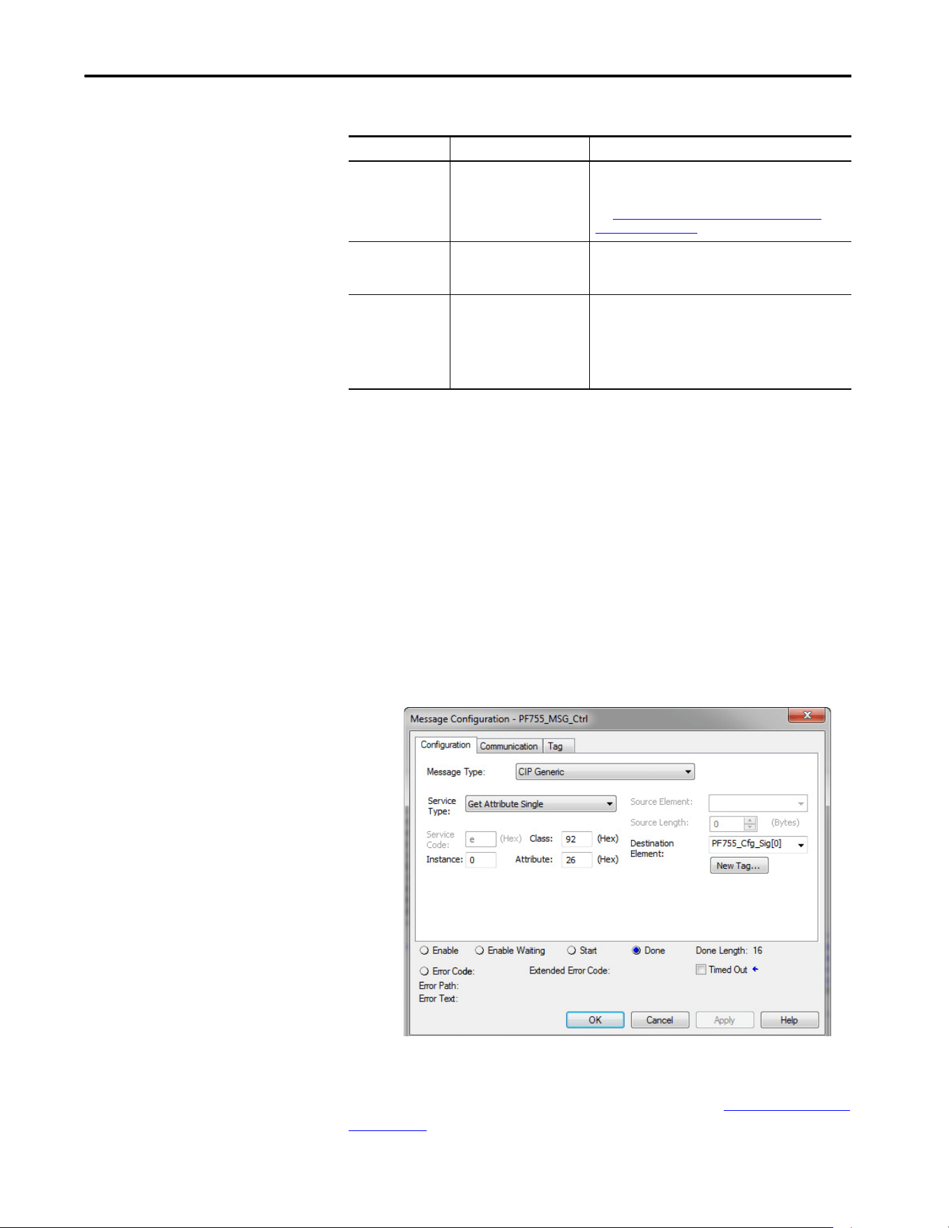
Rockwell Automation Publication 750COM-UM009A-EN-P - May 2017 83
Configuring the Drive in a Logix System Chapter 3
Programmatically
Monitoring Connection
Status and the ADC
Configuration Signature
The Ethernet connection status between the Logix controller and PowerFlex
drive can be monitored using a GSV instruction.
•Class: Module
• Instance: {name of drive in project}
• Attribute: Entry status (returns a value that indicates status)
See the RSLogix 5000 / Studio 5000 application Help for more information
on the GSV Instruction, GSV/SSV Objects, and the Module Object.
The Configuration Signature for a given Port in the PowerFlex drive can be
monitored using an MSG instruction. The following MSG instruction reads
the Configuration Signature from Port 0 in a PowerFlex drive.
The MSG instruction Get Attribute Single uses the DPI™ Device Object
(Class 92 Hex) to access Port 0 in drive (Instance 0). It then reads the
Configuration Signature (Attribute 26 Hex = 38 Dec). See DPI Device Object
on page 138 for additional information.
ADC doesn’t
complete when 20-
750-S1 (S1) option
module is used.
Required manual steps to
unlock/lock and set the
password are not performed.
ADC is not fully automatic when used with a 20-750-S1
(S1) module. Safety systems have a mandatory
requirement for manual steps in the configuration process.
See Special Considerations For 20-750-S1 Safe Speed
Module (S1) on page 75 for more information.
ADC fails due to
parameter out of
range error.
The Min/Max on a parameter
was affected when another
parameter was adjusted.
Out of range parameters have a red highlight in the Linear
List parameter editor. Locate and correct any out of range
parameters.
Drive is at default
configuration
settings after ADC is
performed
(equivalent to a
Reset to Defaults).
Drive configuration did not
upload and save to the drive
AOP and was not saved in the
ACD project that is
downloaded to the controller.
Can occur when a second software tool is being used to
configure the drive. A second tool is not necessary and not
recommended. Upload the configuration from the drive
and save it in the drive AOP. Download project to controller.
Table 5 - Logix Control ADC Failure Examples
Scenario/Error Probable Cause Potential Solutions
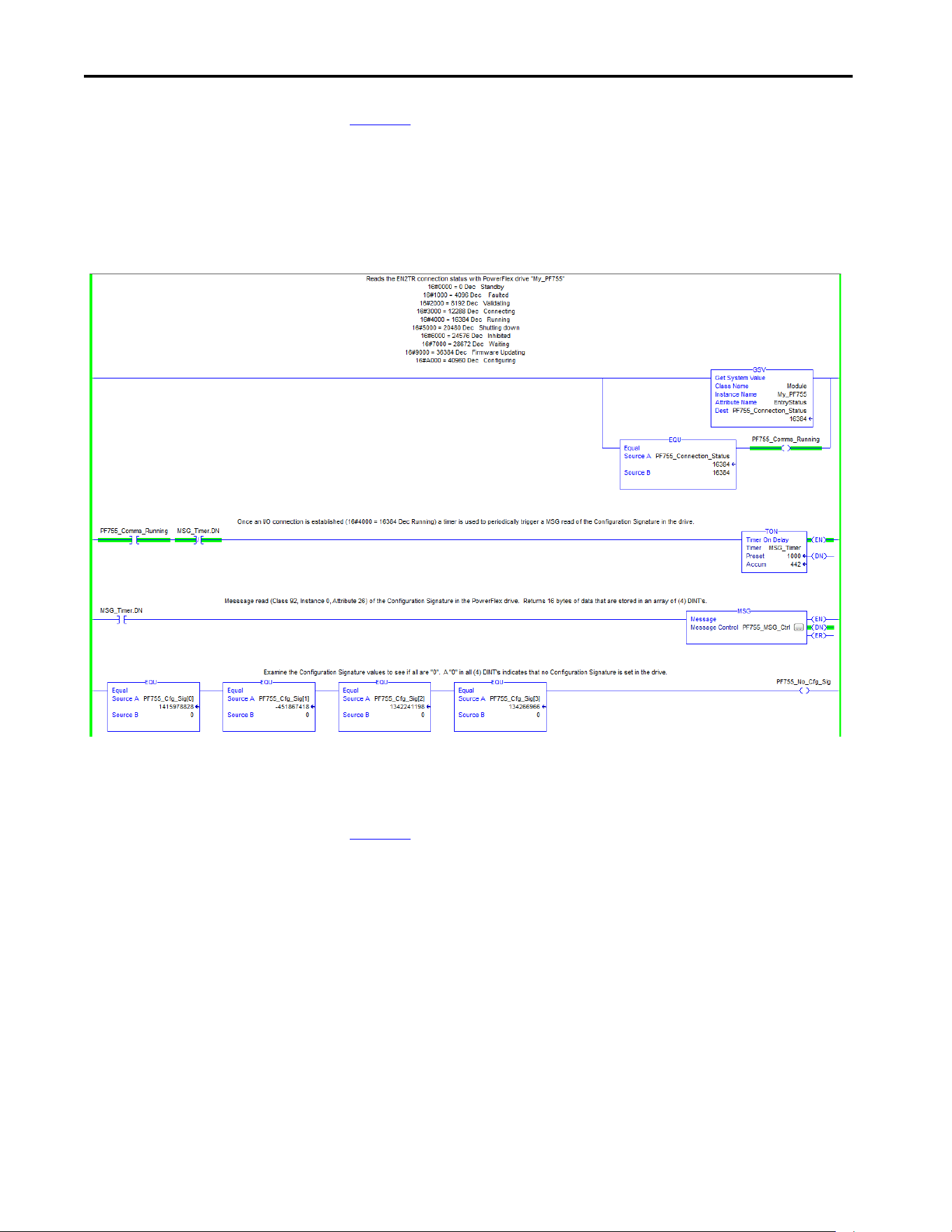
84 Rockwell Automation Publication 750COM-UM009A-EN-P - May 2017
Chapter 3 Configuring the Drive in a Logix System
Figure 13 shows an example Logix program that monitors the Ethernet
connection status to the PowerFlex drive and checks for a Configuration
Signature in Port 0 in the drive. If the connection is running (4000 Hex =
16384 Dec), a timer is used to read the Configuration Signature periodically in
Port 0 in the drive. If there is no Configuration Signature present, all read data
are zeros.
Figure 13 - Example of the Logix Program
Additional MSG instructions would be required to read the Configuration
Signatures in the other ports.
Figure 13
is an example only and is optional. The GSV is good way to check
Ethernet connection status for program use and to display status on an HIM. A
Running connection to control the drive is required. If ADC is enabled, the
Running status confirms a successful ADC download. The status information
that is displayed is the same as when online with the AOP.
Reading the Configuration Signature is not typical, but could be used to detect
and annunciate that a configuration change was made. When a configuration
change is made, ADC triggers and downloads on the next I/O connection. A
drive may not power cycle or reset for a considerable time, it could be days or
months before an I/O connection is dropped and re-established to allow ADC
to occur. When ADC does occur, it overwrites any changes that were made
outside of the drive AOP.

Rockwell Automation Publication 750COM-UM009A-EN-P - May 2017 85
Configuring the Drive in a Logix System Chapter 3
Best Practices
When using ADC in your control system, adhere to the following
recommendations:
• To configure a drive, use only the Studio 5000 environment drive AOP.
If another tool is used to configure the drive, complete the drive
configuration and then upload the configuration to the drive AOP and
save your project. Use the drive AOP for any future configuration
changes. A HIM or CCW can still be used, but only for monitoring.
• Enable ADC as the last step in the commissioning process, after all drive
configurations have been completed. By enabling ADC as the last step, it
inhibits ADC downloads from being triggered after any parameter
adjustments are made during the commissioning process.
• Upload the configuration from the drive before ADC is enabled. This
action makes sure that rating, peripherals, firmware revisions, and
parameter configuration settings in the ACD project match the settings
in the drive.
• Enable and test ADC with one drive or a small group of drives before
enabling it for the remaining drives in the control system. Apply any
lessons learned to the configuration settings of the other drives in the
project. Verify that ADC is successfully working before proceeding to
enable it on other drives.
• After testing ADC with an initial drive, enable ADC in small groups of
drives at a time (for example, five drives). Make sure all drives
successfully come up on the network and are operational before
proceeding to the next group.

86 Rockwell Automation Publication 750COM-UM009A-EN-P - May 2017
Chapter 3 Configuring the Drive in a Logix System
Notes:
Rockwell Automation Publication 750COM-UM009A-EN-P - May 2017 87
Chapter 4
Using the I/O
This chapter provides information and examples that explain how to control,
configure, and monitor PowerFlex® 755T drives by using the configured I/O.
This chapter discusses how to use I/O after you have configured the interface
and controller.
To configure the interface and controller on the network for the required I/O
see Chapter 2
, Configure the interface, and Chapter 3, Configuring the drive
in a Logix System. The Glossary
defines the different options.
About I/O Messaging
On CIP-based networks, including EtherNet/IP and I/O connections, are
used to transfer the data that controls the PowerFlex drive and sets its reference.
I/O connections can also be used to transfer data to and from datalinks in
PowerFlex 755T drives.
The interface includes the logic command, logic status, reference, feedback,
and memory allocation for the generic Ethernet module profile (all as 32-bit
words) in the I/O image of the controller. This basic I/O must be configured
Topic Page
About I/O Messaging 87
Understanding the ControlLogix Controller I/O Image 88
Using Logic Command/Status 89
Using Reference/Feedback 89
Using Datalinks 91
Example of Ladder Logic Program Information 92
Functions of the Example Programs 92
Logic Command/Status Words 92
ControlLogix Controller Example 92
Create Ladder Logic Using the RSLogix or Studio 5000 with Drive Add-on
Profiles
92
ATTENTION: Risk of injury or equipment damage exists. The examples in this
publication are intended solely for purposes of example. There are many
variables and requirements with any application. Rockwell Automation does not
assume responsibility or liability (to include intellectual property liability) for
actual use of the examples that are shown in this publication.

88 Rockwell Automation Publication 750COM-UM009A-EN-P - May 2017
Chapter 4 Using the I/O
in the Ethernet bridge using the RSLogix 5000® / Studio 5000® environment.
Additional I/O, if needed, can be set using up to 16 datalinks to write data
and/or up to 16 datalinks to read data. When using any combination of these
datalinks, add one 32-bit word for each datalink to the basic I/O Input Size
and/or Output Size.
Understanding the
ControlLogix Controller I/O
Image
The terms input and output are defined from the point of view of the
controller. Therefore, output I/O is controller produced data that is used by
the drive. Input I/O is drive produced status data that is used as input by the
controller. The I/O image varies based on the following:
• How many of the 32-bit datalinks (DL From Net 01…16 and DL To
Net 01…16) for the drive are used.
• ControlLogix®/CompactLogix™ Controllers only - The drive profile
that is used in RSLogix 5000 software, version 20 and Studio 5000
environment, version 21 or later. Add-on Profile is version 1.xx or later.
The drive Add-on Profile in the RSLogix 5000 and Studio 5000 environments
provide descriptive controller tags. The I/O image (tag size and location) is
automatically configured based on the drive being used. A generic profile also
exists and could be used.

Rockwell Automation Publication 750COM-UM009A-EN-P - May 2017 89
Using the I/O Chapter 4
Tab le 6 shows the I/O image when using all 32-bit datalinks.
Using Logic Command/Status
The controller produces the logic command, a 32-bit word of control data,
which is used by the drive or bus supply. The drive or bus supply produces logic
status, a 32-bit word of status data, which is used by the controller.
When using a ControlLogix controller with the drive Add-on Profile, the logic
command word is always DINT 0 in the output image. The logic status word is
always DINT 0 in the input image.
This manual contains the bit definitions for compatible products available at
the time of publication in Appendix E
, Logic Command/Status Words:
PowerFlex 755T drives and Bus Supplies.
Using Reference/Feedback
The controller produces the reference, a 32-bit REAL (floating point) word of
control data that is used by the PowerFlex drives 755TL, 755TR, or 755TM
common bus inverter. The drive or bus supply produces feedback, a 32-bit
REAL (floating point) word of status data, which is used by the controller.
Table 6 - ControlLogix I/O Image for PowerFlex 755T Drives
(32-bit Logic Command/Status, Reference/Feedback, and Datalinks)
DINT Output (Controller to Drive) I/O DINT Input (Drive to Controller) I/O
0Logic Command 0Logic Status
1 Reference 1 Feedback
2 DL From Net 01 2 DL To Net 01
3 DL From Net 02 3 DL To Net 02
4 DL From Net 03 4 DL To Net 03
5 DL From Net 04 5 DL To Net 04
6 DL From Net 05 6 DL To Net 05
7 DL From Net 06 7 DL To Net 06
8 DL From Net 07 8 DL To Net 07
9 DL From Net 08 9 DL To Net 08
10 DL From Net 09 10 DL To Net 09
11 DL From Net 10 11 DL To Net 10
12 DL From Net 11 12 DL To Net 11
13 DL From Net 12 13 DL To Net 12
14 DL From Net 13 14 DL To Net 13
15 DL From Net 14 15 DL To Net 14
16 DL From Net 15 16 DL To Net 15
17 DL From Net 16 17 DL To Net 16

90 Rockwell Automation Publication 750COM-UM009A-EN-P - May 2017
Chapter 4 Using the I/O
When using a ControlLogix controller with the drive Add-on Profile, the 32-
bit REAL reference word is always DINT 1 in the output image (see Ta bl e 6
).
The 32-bit REAL feedback word is always DINT 1 in the input image.
When using a drive Add-on Profile, the reference and feedback are
automatically properly formatted and displayed as a controller tag. When using
a generic profile, a COP (copy) instruction or user-defined data type (UDDT)
is required to write values to the reference and read values from the feedback.
The reference and feedback 32-bit REAL values represent drive velocity. The
scaling for the speed reference and feedback is dependent on drive 10:1891 -
[Velocity Units]. For example, if Parameter 1891 is set to hertz, a 32-bit REAL
reference value of ‘30.0’ would equal a reference of 30.0 Hz. If Parameter 1891
is set to RPM, a 32-bit REAL reference value of ‘1020.5’ would equal a
reference of 1020.5 RPM. The commanded maximum speed can never exceed
the value of drive 10:1392 - [Max Speed Fwd]. Tab le 7
shows example
references and their results for a PowerFlex 755T drive that has its:
• 10:1891 - [Velocity Units] set to Hz.
• 10:422 - [Maximum Freq] set to 130 Hz.
• 10:1392 - [Max Speed Fwd] set to 60 Hz.
When 10:1891 - [Velocity Units] is set to RPM, the other parameters are also
in RPM.
Table 7 - PowerFlex755T Drives Example Velocity Reference/Feedback Scaling
Network Reference Value Velocity Command Value
(2)
Output Velocity Network Feedback Value
130.0 130 Hz 60 Hz
(3)
60.0
65.0 65 Hz 60 Hz
(3)
60.0
32.5 32.5 Hz 32.5 Hz 32.5
0.0 0 Hz 0 Hz 0.0
-32.5
(1)
32.5 Hz 32.5 Hz 32.5
(1) The effects of values less than 0.0 depend on whether the PowerFlex 755T drive uses a bipolar or unipolar direction mode. See the
drive documentation for details.
(2) For this example, drive 10:1891 - [Velocity Units] is set to Hz.
(3) The drive runs at 60 Hz instead of 130 Hz or 65 Hz because drive 10:1392 - [Max Speed Fwd] sets 60 Hz as the Maximum velocity.

Rockwell Automation Publication 750COM-UM009A-EN-P - May 2017 91
Using the I/O Chapter 4
Using Datalinks
A datalink is a mechanism that is used by PowerFlex drives to transfer data to
and from the controller. Datalinks allow a drive parameter value to be read or
written to without using an explicit message. When enabled, each datalink
occupies one 32-bit word in a ControlLogix controller.
The following rules apply when using PowerFlex 755T drive datalinks:
• The target of a datalink can be any Host parameter, including host
parameters of a peripheral. For example, drive 10:1915 - [VRef Accel
Time 1] can be the target of the built-in EtherNet/IP interface and any
or all option modules that are installed in the drive.
•The settings of 0:321…336 - [DL From Net 01…16] and
0:340…355 - [DL To Net 01…16] determine the data that is passed
through the datalink mechanism of the drive.
• When an I/O connection that includes datalinks is active, those
datalinks being used are locked and cannot be changed until that I/O
connection becomes idle or inactive.
• When you use a datalink to change a value, the value is not written to
the nonvolatile storage (NVS). The value is stored in volatile memory
and lost when the drive loses power. Use datalinks to change the value of
a parameter frequently.
Datalinks for PowerFlex 755T peripherals are locked when the peripheral has
an I/O connection with a controller. For example, the built-in EtherNet/IP
interface on PowerFlex 755T drives only, and option modules such as an
encoder or a communication module. When a controller has an I/O
connection to the drive, the drive does not allow anything that could change
the makeup of the I/O connection in a running system. For example, a reset to
defaults and configuration download. The I/O connection with the controller
must first be disabled to allow changes to the respective datalinks.
Depending on the controller being used, the I/O connection can be disabled
by doing the following:
• Inhibiting the module in Studio 5000 or RSLogix 5000 environment
• Putting the controller in Program mode
• Disconnecting the drive from the network

92 Rockwell Automation Publication 750COM-UM009A-EN-P - May 2017
Chapter 4 Using the I/O
Example of Ladder Logic
Program Information
The example ladder logic programs in this chapter are intended for and operate
PowerFlex 755T drives.
Functions of the Example Programs
The following can be accomplished by using the example programs.
• Receive logic status information from the drive.
• Send a logic command to control the drive (for example, start, stop).
• Send a reference to the drive and receive feedback from the drive.
• Send/receive datalink data to/from the drive.
Logic Command/Status Words
These examples use the logic command word and logic status word for
PowerFlex 755T drives. See Appendix E
, Logic Command/Status Words:
PowerFlex 755T drives and Bus Supplies to view details.
ControlLogix Controller
Example
This section includes information on how to use a ControlLogix controller,
and an RSLogix 5000 or Studio5000 drive Add-on Profile.
For information on how to use a PLC-5®, SLC™ 500, or MicroLogix™ 1100/
1400 controller or how to use the Logix controller Generic ETHERNET-
MODULE profile, see Controller Examples for EtherNet/IP network
communication with PowerFlex 750-Drives, publication 750COM-AT001
.
Create Ladder Logic Using the RSLogix or Studio 5000 with Drive
Add-on Profiles
The drive Add-on Profile automatically creates descriptive controller tags
(Figure 10
) for the entire I/O image in Chapter 3. Use these tags to control and
monitor the drive without creating any ladder logic program. However, if HIM
devices (for example, a PanelView™ graphic terminal) are used to operate the
drive and view its status, create descriptive user-defined Program tags
(Figure 14
). Also create a ladder logic program that passes the Controller tag
data to the Program tags. The drive profile that is used in RSLogix 5000
software, is version 20 and Studio 5000 environment, is version 21 or later with
Add-on Profile version 1.xx or later.
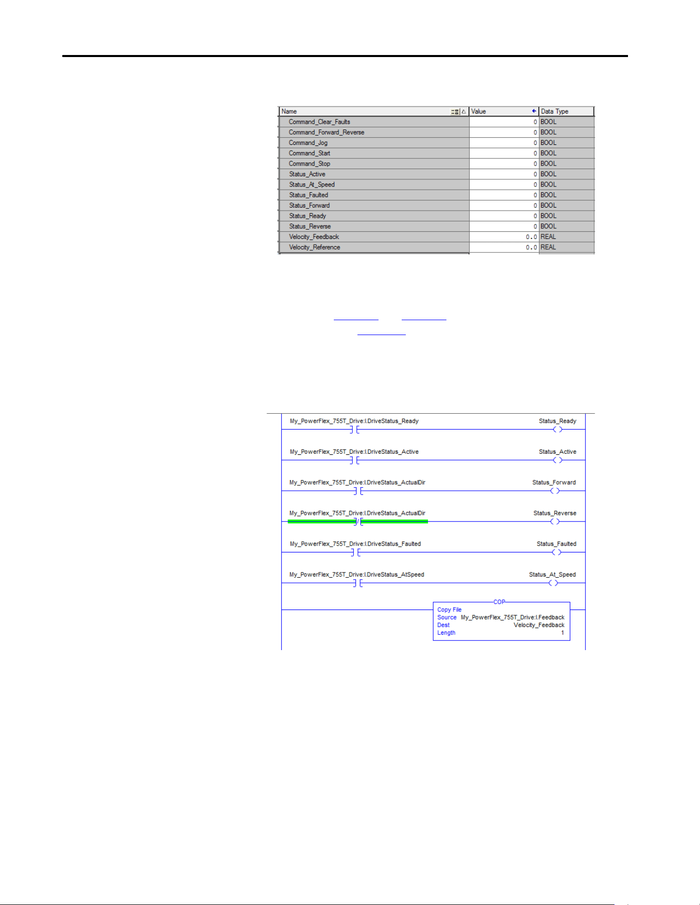
Rockwell Automation Publication 750COM-UM009A-EN-P - May 2017 93
Using the I/O Chapter 4
Figure 14 - ControlLogix Program Tags for Drive Add-on Profile Ladder Logic Program Example
An example ladder logic program that uses the automatically created
descriptive Controller tags and passes their data to the user-defined Program
tags is shown in Figure 15
and Figure 16. The name that is assigned when
configuring the I/O (Chapter 3
) determines the prefix for the drive Controller
tags.
Figure 15 - ControlLogix Controller Example Ladder Logic Program Using a Drive Add-on Profile
for Logic Status/Feedback
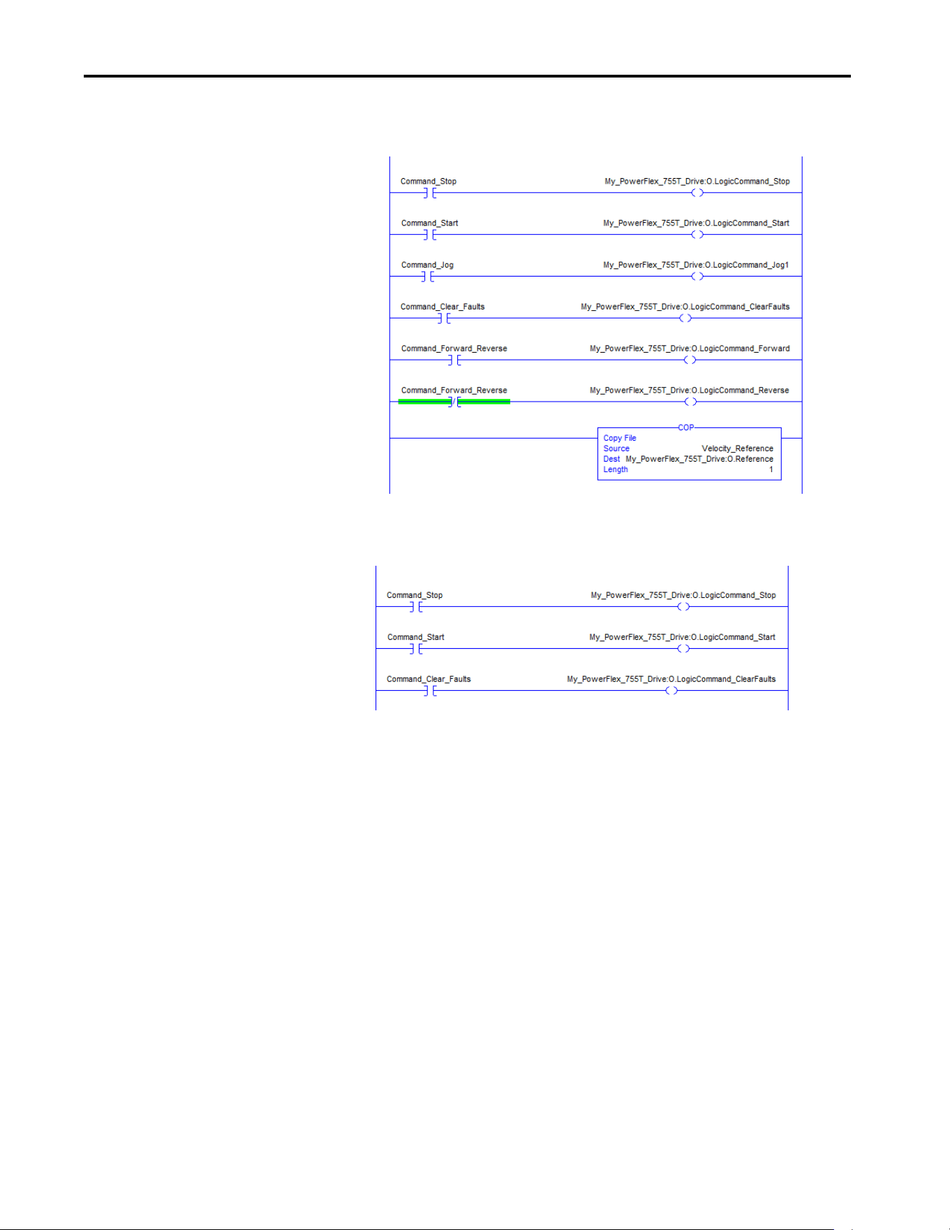
94 Rockwell Automation Publication 750COM-UM009A-EN-P - May 2017
Chapter 4 Using the I/O
Figure 16 - ControlLogix Controller Example Ladder Logic Program Using a Drive Add-on Profile
for Logic Command/Reference
Figure 17 - ControlLogix Controller Example Ladder Logic Program Using a Drive Add-on Profile
for Logic Command/Reference for a Converter

Rockwell Automation Publication 750COM-UM009A-EN-P - May 2017 95
Chapter 5
Using Explicit Messaging
This chapter provides information and examples that explain how to use
Explicit Messaging with a ControlLogix® controller to configure and monitor
the interface and connected PowerFlex® 755TR, 755TL, 755TM drives, and
755TM Bus Supply.
For information on how to use a PLC-5®, SLC™ 500, or MicroLogix™ 1100/
1400 controller, see Controller Examples for EtherNet/IP Network
communication with PowerFlex 750-Drives, publication 750COM-AT001
.
See Chapter 4
for information about the I/O Image, the use of logic
command/status, reference/feedback, and datalinks.
Topic Page
About Explicit Messaging 96
Performing Explicit Messaging 98
ControlLogix Controller Examples 99
Ladder Logic Program to Read a Single Parameter 99
Formatting a Message to Read a Single Parameter 100
Ladder Logic Program to Write a Single Parameter 101
Formatting a Message to Write a Single Parameter 102
Ladder Logic Program to Read Multiple Parameters 103
Formatting a Message to Read Multiple Parameters 104
Ladder Logic Program to Write Multiple Parameters 106
Formatting a Message to Write Multiple Parameters 107
Explanation of Request and Response Data for Scattered Read Multiple Messaging 109
IMPORTANT The drive saves parameter values that are written through Scattered Write
messages into the drives nonvolatile storage (NVS). The NVS allows only a
limited number of write cycles before it cannot store data reliably. To avoid
reaching this limit, do not use the Scattered Write messages for continuous
changes to parameter values.
If a parameter value must be changed continuously, you can use the
datalinks that are associated with the Logix controller's I/O connection, or
you can use individual parameter write messages that store the values that
are written to random access memory (RAM) rather than nonvolatile storage
(NVS) (see class 0x93, instance attribute 10, on page 147
).

96 Rockwell Automation Publication 750COM-UM009A-EN-P - May 2017
Chapter 5 Using Explicit Messaging
About Explicit Messaging
Explicit Messaging is used to transfer data that does not require continuous
updates. With Explicit Messaging, you can configure and monitor the
parameters of a controlling device on the network.
Table 8 - Explicit Messaging Class Code Compatibility with PowerFlex 755T Drive
TIP To message to another device in another drive port, see the Instance table in
Appendix C:
• DPI™ Parameter Object section on page 145
for Device parameters.
• Host DPI Parameter Object section on page 154
for Host parameters.
In the Message Configuration dialog box, set the Instance field to an
appropriate value within the range that is listed for the port in which the
device resides.
IMPORTANT PowerFlex 755T drives have Explicit Messaging limitations. Tabl e 8
shows
the EtherNet/IP Object Class code compatibilities for these drives.
EtherNet/IP Object Class Code Compatibility Explicit Messaging Function
Parameter Object 0x0F No Not supported.
DPI Parameter Object 0x93 Yes (See Table 6) Single and scattered parameter reads/writes.
Host DPI Parameter Object 0x9F Yes (See Table 6) Single and scattered parameter reads/writes.

Rockwell Automation Publication 750COM-UM009A-EN-P - May 2017 97
Using Explicit Messaging Chapter 5
Table 9 - Explicit Messaging Compatibility with PowerFlex 755T Drive
Port Number Host (Drive) Parameters Device Parameters
0 Class 0x93 or 0x9F —
1 — Class 0x93
2 — Class 0x93
3 — Class 0x93
4 Class 0x9F
(1)
(1) Class 0x93 can be used to access the Host parameters if the device at this port has no Device parameters.
See DPI Parameter Object on page 145 for instance (parameter)
numbering.
Class 0x93
5 Class 0x9F
(1)
Class 0x93
6 Class 0x9F
(1)
Class 0x93
7 Class 0x93 or 0x9F —
8 Class 0x93 or 0x9F —
9 Class 0x93 or 0x9F —
10 Class 0x93 or 0x9F —
11 Class 0x93 or 0x9F —
12 Class 0x93 or 0x9F —
13 Class 0x93 or 0x9F —
14 Class 0x93 or 0x9F —
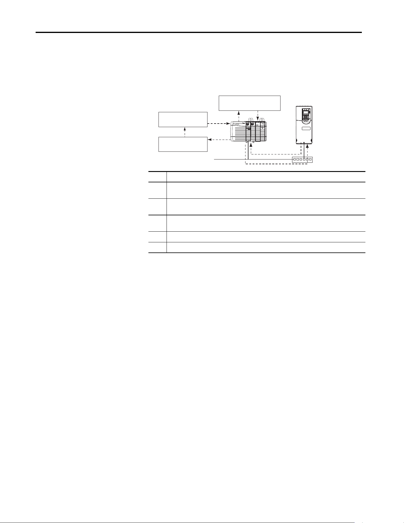
98 Rockwell Automation Publication 750COM-UM009A-EN-P - May 2017
Chapter 5 Using Explicit Messaging
Performing Explicit
Messaging
There are five basic events in the Explicit Messaging process. The details of
each step vary depending on the type of controller being used. See the
documentation for your controller.
Figure 18 - Explicit Message Process
For information on the maximum number of Explicit Messages that can be
executed at a time, see the documentation for the bridge or communication
bridge and/or controller that is being used.
Event Description
1 You format the required data and configure the ladder logic program to send an Explicit Message request to
the communication bridge (download).
2 The communication bridge transmits the Explicit Message Request to the controlled device over the
network.
3 The controlled device transmits the Explicit Message Response back to the communication bridge. The data
is stored in the communication bridge buffer.
4 The controller retrieves the Explicit Message Response from the communication bridge buffer.
5 The Explicit Message is complete.
Complete Explicit
Message
Retrieve Explicit
Message Response
Configure and send Explicit
Message Request
Ethernet
Switch
Network
1
5
4
2
3
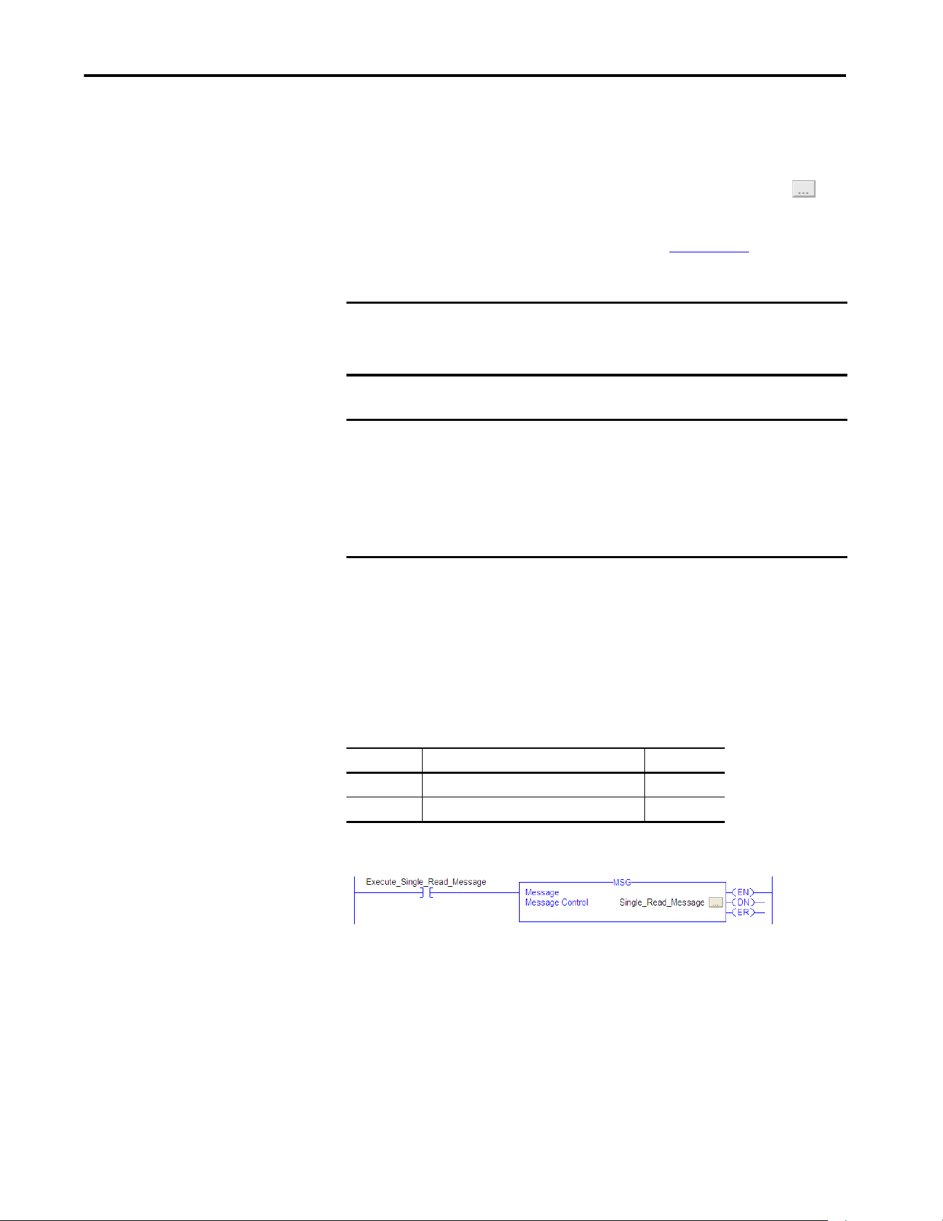
Rockwell Automation Publication 750COM-UM009A-EN-P - May 2017 99
Using Explicit Messaging Chapter 5
ControlLogix Controller
Examples
For supported classes, instances, and attributes, see Appendix D, EtherNet/IP
Objects.
Ladder Logic Program to Read a Single Parameter
A Get Attribute Single message is used to read a parameter. This read message
example reads the value of the 32-bit REAL (floating point) 10:3 - [Output
Current] in a PowerFlex 755T drive.
Table 10 - Example Controller Tags to Read a Single Parameter
Figure 19 - Example Ladder Logic to Read a Single Parameter
TIP To display the Message Configuration dialog box in RSLogix 5000® software,
add a message instruction (MSG), create a tag for the message (Properties:
Base tag type, message data type, controller scope), and click the
button in the message instruction.
IMPORTANT The Explicit Messaging examples in this section can be performed with
RSLogix 5000 software version 20 or Studio 5000® application, version 21 or
later.
IMPORTANT The read and write messaging examples in this section are for Device
parameters, which use Class Code 0x93. For Host parameters, use Class Code
0x9F and format the rest of the message in the same way as these examples.
Do not use the Service Type Parameter Read, which accesses the Parameter
object (class 0x0F). The Parameter object is not supported in PowerFlex 755T
drives.
Operand Controller Tags for Single Read Message Data Type
XIC Execute_Single_Read_Message BOOL
MSG Single_Read_Message MESSAGE
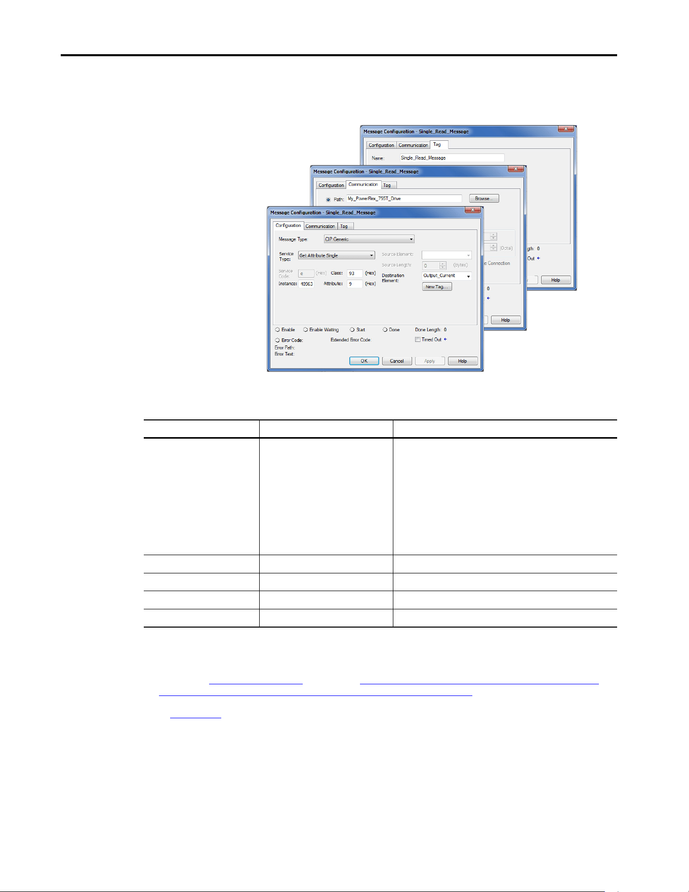
100 Rockwell Automation Publication 750COM-UM009A-EN-P - May 2017
Chapter 5 Using Explicit Messaging
Formatting a Message to Read a Single Parameter
Figure 20 - Get Attribute Single Message, Configuration Dialog-boxes
The following table identifies the data that is required in each box to configure
a message to read a parameter.
Configuration Tab Example Value Description
Message Type
Service Type
(1)
Service Code
(1)
Class
Instance
(2)
Attribute
Source Element
Source Length
Destination
CIP Generic (network)
Get Attribute Single
e (hexadecimal)
93 or 9F (hexadecimal)
(4)
40963 (Dec.)
9 (hexadecimal)
—
0-bytes
Output_Current
(5)
Used to access the DPI Parameter Object in the drive.
This service is used to read a parameter value.
Code for the requested service.
Class ID for the DPI Parameter Object or Host DPI Parameter Object.
Instance number is parameter number plus port offset.
Attribute number for the Parameter Value attribute.
Leave blank (not applicable).
Number of bytes of service data to be sent in the message.
The tag where the data that is read is stored.
Communication Tab Example Value Description
Path
(3)
My_PowerFlex_755T_Drive The path is the route that the message follows.
Tag Tab Example Value Description
Name Single_Read_Message The name for the message.
(1) The default setting for Service Type is ‘Custom’, which enables the entry of a Service Code not available from the Service Type pull-down menu. When choosing a Service
Type other than ‘Custom’ from the pull-down menu, the appropriate hexadecimal value is automatically assigned to the Service Code box, which is dimmed
(unavailable).
(2) The instance is the parameter number plus the offset for the port. For example, to read 10:3 - [Output Current] of a PowerFlex 755T drive, the instance would be 40960
+ 3 = 40963. See DPI Parameter Object on page 145
(Class code 0x93) or The number of instances depends on the maximum number of faults or events that are
supported in the queue. The maximum number of faults/events can be read in Instance 0, Attribute 2. on page 154 (Class code 0x9F) to determine the instance number.
(3) Click Browse to find the path, or type in the name of the device listed in the I/O Configuration folder (for this example, My_PowerFlex_755T_Drive).
(4) See Table 8 on page 96
for limitations of PowerFlex 755T drives when using DPI Parameter Object Class code 0x93 or Host DPI Parameter Object Class code 0x9F for
Explicit Messaging.
(5) In this example, Output Current is a 32-bit REAL (floating point) parameter that requires the Data Type field to be set to ‘REAL’ when creating the controller tag. To read a
32-bit integer parameter, set the tag Data Type field to ‘DINT’. For a 16-bit parameter, set the Data Type field to ‘INT’. See the drive documentation to determine the size
of the parameter and its data type.
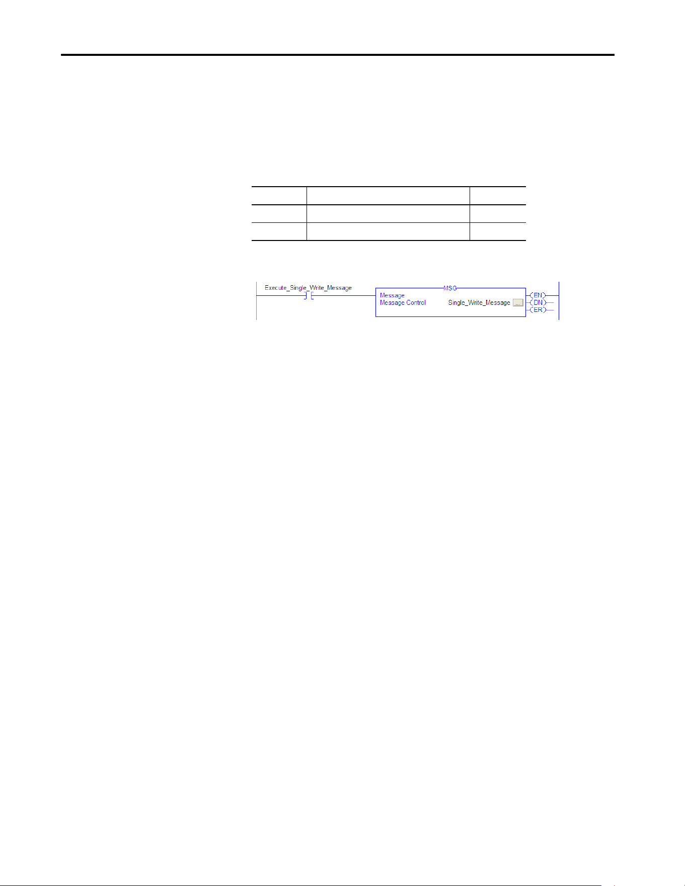
Rockwell Automation Publication 750COM-UM009A-EN-P - May 2017 101
Using Explicit Messaging Chapter 5
Ladder Logic Program to Write a Single Parameter
A Set Attribute Single message is used to write to a parameter. This write
message example writes a value to the 32-bit REAL (floating point) 10: 1915 -
[VRef Accel Time 1] in a PowerFlex 755T drive.
Table 11 - Example Controller Tags to Write a Single Parameter
Figure 21 - Example Ladder Logic to Write a Single Parameter
Operand Controller Tags for Single Write Message Data Type
XIC Execute_Single_Write_Message BOOL
MSG Single_Write_Message MESSAGE
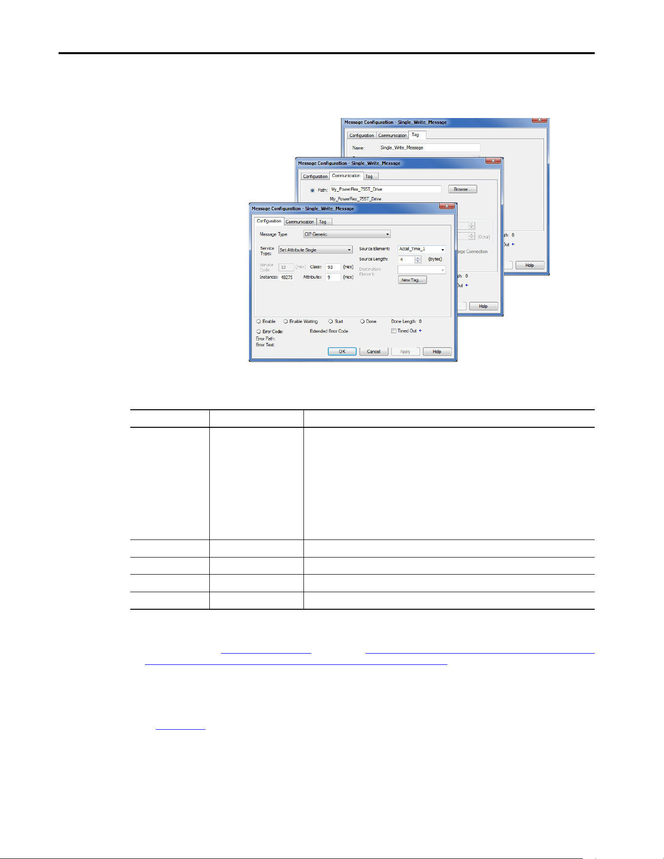
102 Rockwell Automation Publication 750COM-UM009A-EN-P - May 2017
Chapter 5 Using Explicit Messaging
Formatting a Message to Write a Single Parameter
Figure 22 - Set Attribute Single Message, Configuration Dialog-boxes
The following table identifies the data that is required in each box to configure
a message to write a parameter.
Configuration Tab Example Value Description
Message Type
Service Type
(1)
Service Code
(1)
Class
Instance
(2)
Attribute
(3)
Source Element
Source Length
Destination
CIP Generic (network)
Set Attribute Single
10 (hexadecimal)
93 or 9F (hexadecimal)
(5)
42875 (Dec.)
9 or A (hexadecimal)
Accel_Time_1
(6)
4-bytes
(6)
—
Used to access the DPI Parameter Object in the drive.
This service is used to write a parameter value.
Code for the requested service.
Class ID for the Class ID for the DPI Parameter Object or Host DPI Parameter Object.
Instance number is the parameter number plus the port offset
Attribute number for the Parameter Value attribute.
The tag where the data that is written is stored
Number of bytes of service data to be sent in the message.
Leave blank (not applicable).
Communication Tab Example Value Description
Path
(4)
My_PowerFlex_755T_Drive The path is the route that the message follows.
Tag Tab Example Value Description
Name Single_Write_Message The name for the message.
(1) The default setting for Service Type is ‘Custom’, which enables the entry of a Service Code not available from the Service Type pull-down menu. When choosing a Service
Type other than ‘Custom’ from the pull-down menu, the appropriate hexadecimal value is automatically assigned to the Service Code box, which is dimmed (unavailable).
(2) The instance is the parameter number plus the offset for the port. For example, to write to a 10:1915 [Vref Accel Time 1] of a PowerFlex 755T drive, the instance would be
40960 + 1915 = 42875. See DPI Parameter Object on page 145
(Class code 0x93) or The number of instances depends on the maximum number of faults or events that are
supported in the queue. The maximum number of faults/events can be read in Instance 0, Attribute 2. on page 154 (Class code 0x9F) to determine the instance number.
(3) When the Attribute value is set to ‘9’, the parameter value is written to nonvolatile storage (NVS) of the drive. The drive retains the parameter value even after the drive
power is cycled. Important: When set to ‘9’, the NVS can quickly exceed its lifecycle and cause the drive to malfunction. By setting the Attribute value to ‘A’ it writes the
parameter value to temporary memory, which deletes the parameter value after the drive power is cycled. When frequent write messages are required, we recommended
using the ‘A’ setting.
(4) Click ‘Browse’ to find the path, or type in the name of the device listed in the I/O Configuration folder (for this example, My_PowerFlex_755T_Drive).
(5) See Table 8 on page 96
for limitations of PowerFlex 755T drives when using DPI Parameter Object Class code 0x93 or Host DPI Parameter Object Class code 0x9F for Explicit
Messaging.
(6) In this example, Accel Time 1 is a 32-bit REAL (floating point) parameter that requires the Data Type field to be set to ‘REAL’ when creating the controller tag. To write to a
32-bit integer parameter, set the tag Data Type field to ‘DINT’. For a 16-bit parameter, set the Data Type field to ‘INT’. Also, the Source Length field on the Message
Configuration dialog box must correspond to the selected Data Type in bytes. For example, 4-bytes for a REAL or DINT, or 2-bytes for an INT. See the drive documentation to
determine the size of the parameter and its data type.
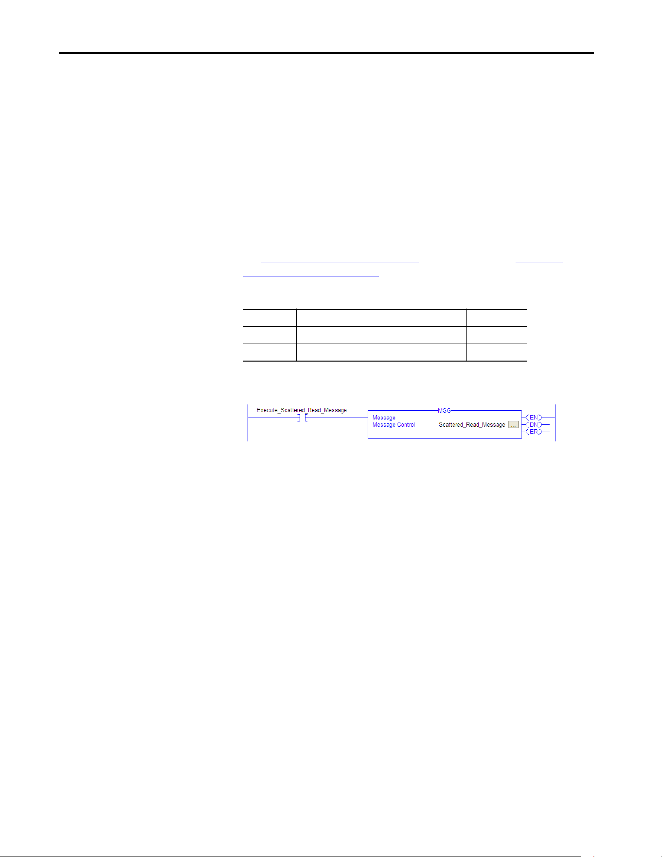
Rockwell Automation Publication 750COM-UM009A-EN-P - May 2017 103
Using Explicit Messaging Chapter 5
Ladder Logic Program to Read Multiple Parameters
A Scattered Read message is used to read the values of multiple parameters.
This read message example reads the values of these floating point parameters
(five 32-bit REAL) in a PowerFlex 755T drive:
• 10:001 - [Output Frequency]
• 10:003 - [Output Current]
• 10:002 - [Output Voltage]
• 10:004 - [Output Power]
• 0:003 - [DC Bus Volts]
See DPI Parameter Object on page 145
(Class code 0x93) or Host DPI
Parameter Object on page 163 (Class code 0x9F) for parameter numbering.
Table 12 - Example Controller Tags to Read Multiple Parameters
Figure 23 - Example Ladder Logic to Read Multiple Parameters
Operand Controller Tags for Scattered Read Message Data Type
XIC Execute_Scattered_Read_Message BOOL
MSG Scattered_Read_Message MESSAGE
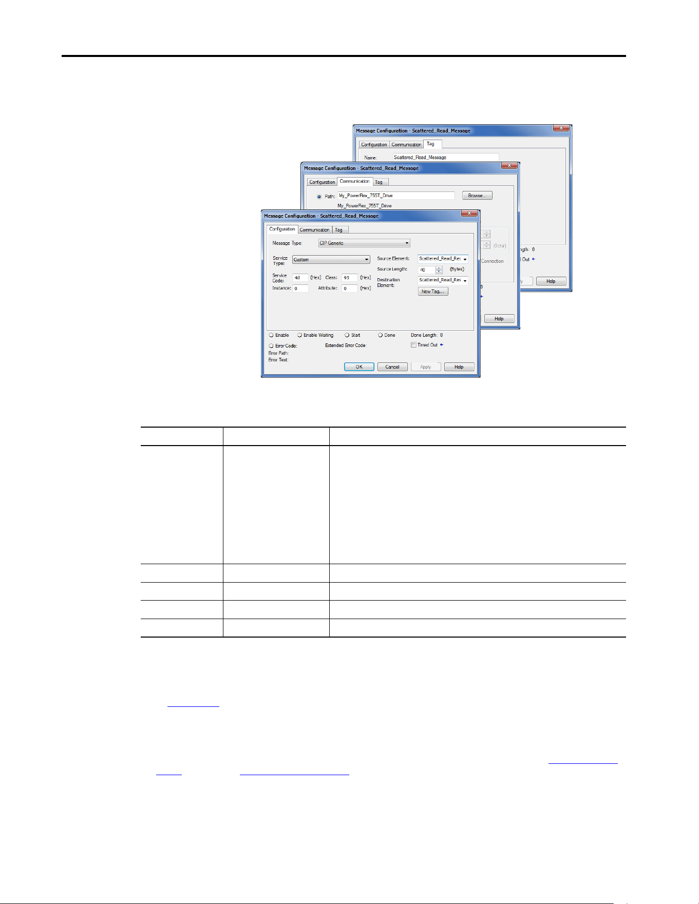
104 Rockwell Automation Publication 750COM-UM009A-EN-P - May 2017
Chapter 5 Using Explicit Messaging
Formatting a Message to Read Multiple Parameters
Figure 24 - Scattered Read Message Configuration Dialog-boxes
The following table identifies the data that is required in each box to configure
a message to read multiple parameters.
Configuration Tab Example Value Description
Message Type
Service Type
(1)
Service Code
(1)
Class
Instance
Attribute
Source Element
Source Length
Destination
CIP Generic (network)
Custom
4d (hexadecimal)
93 or 9F (hexadecimal)
(3)
0 (Dec.)
0 (hexadecimal)
Scattered_Read_Request
(4)
40-bytes
(4)
Scattered_Read_Response
(5)
Used to access the DPI Parameter Object in the drive.
Required for scattered read messages.
Code for the requested service.
Class ID for the Class ID for the DPI Parameter Object or Host DPI Parameter Object.
Required for scattered read messages.
Required for scattered read messages.
The tag for the request service data.
Number of bytes of request service data.
The tag for the response service data.
Communication Tab Example Value Description
Path
(2)
My_PowerFlex_755T_Drive The path is the route that the message follows.
Tag Tab Example Value Description
Name Scattered_Read_Message The name for the message.
(1) The default setting for Service Type is ‘Custom’, which enables the entry of a Service Code not available from the Service Type pull-down menu. When choosing a Service
Type other than ‘Custom’ from the pull-down menu, the appropriate hexadecimal value is automatically assigned to the Service Code box, which is dimmed (unavailable).
When reading 32-bit REAL (floating point) parameters, as in this example, data conversion by using COP (copy) instructions or UDDTs is required to show the parameter
values.
(2) Click ‘Browse’ to find the path, or type in the name of the device listed in the I/O Configuration folder (for this example, My_PowerFlex_755T_Drive).
(3) See Table 8 on page 96
for limitations of PowerFlex 755T drives when using DPI Parameter Object Class code 0x93 or Host DPI Parameter Object Class code 0x9F for Explicit
Messaging.
(4) In this example, we are reading five 32-bit REAL (floating point) parameters. Each parameter being read requires two contiguous DINT registers. Therefore, a controller tag
was created with its Data Type field set to ‘DINT[10]’. Also, the Source Length field on the Message Configuration dialog box must correspond to the selected Data Type in
bytes (for this example, 40-bytes for a DINT[10] array). Scattered Read messages always assume that every parameter being read is a 32-bit parameter, regardless of its
actual size. Maximum message length is 256-bytes, which can read up to 32 parameters, regardless of their size. For parameter numbers, see DPI Parameter Object on
page 145 (Class code 0x93) or Host DPI Parameter Object on page 163 (Class code 0x9F).
(5) The controller tag for ‘Scattered_Read_Response’ must be the same size as the controller tag for ‘Scattered_Read_Request’. For this example, 40-bytes, but it can be
another data type (for this example, a UDDT to handle conversions to parameter values that are a REAL data type).
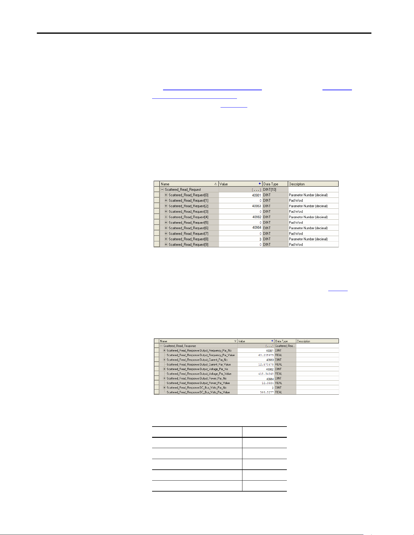
Rockwell Automation Publication 750COM-UM009A-EN-P - May 2017 105
Using Explicit Messaging Chapter 5
ControlLogix Controller Example Scattered Read Request Data
In this message example, the source tag Scattered Read Request, is used to read
the five floating point parameters (32-bit REAL) in the PowerFlex 755T drive.
See DPI Parameter Object on page 145
(Class code 0x93) or Host DPI
Parameter Object on page 163 (Class code 0x9F) for parameter numbering.
See the data structure in Figure 25
.
• 10:001 - [Output Frequency]
• 10:003 - [Output Current]
• 10:002 - [Output Voltage]
• 10:004 - [Output Power]
• 0:003- [DC Bus Volts]
Figure 25 - Example Scattered Read Request Data
ControlLogix Controller Example Scattered Read Response Data
The Scattered Read Request message reads multiple parameters and returns
their values to the destination tag (Scattered_Read_Response). Figure
shows
the parameter values which, in this example, have been converted using a
UDDT for correct presentation. For parameters that are 32-bit integers, do not
COP (copy) the data to a REAL tag. COP (copy) could have been used instead
of a UDDT for parameter less than 32-bits. Example Scattered Read Response
Converted Data
In this message example, the parameters have the following values, the values
are written as Port Number: Parameter Number - [Parameter Name]
PowerFlex 755T Drive Parameter Read Value
10:1 - [Output Frequency] 60.205975 Hz
10:3 - [Output Current] 12.570678 A
10:2 - [Output Voltage] 418.34348V AC
10:4 - [Output Power] 12.3534 kW
0:3 - [DC Bus Volts] 566.5277V DC
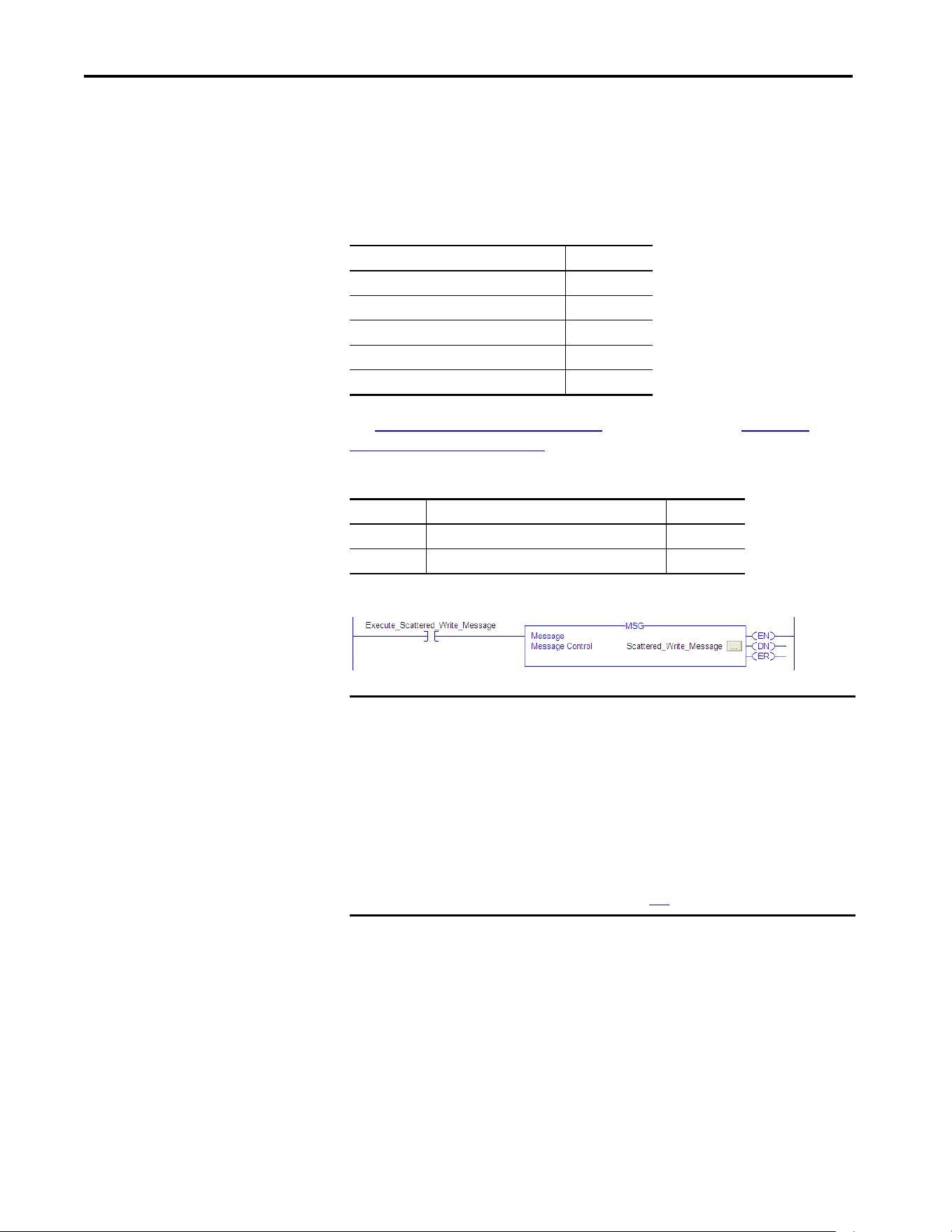
106 Rockwell Automation Publication 750COM-UM009A-EN-P - May 2017
Chapter 5 Using Explicit Messaging
Ladder Logic Program to Write Multiple Parameters
A Scattered Write message is used to write to multiple parameters. This write
message example writes the following values to these floating point (32-bit
REAL) parameters in a PowerFlex 755T drive, the values are written as Port
Number: Parameter Number - [Parameter Name]
See DPI Parameter Object on page 145
(Class code 0x93) or Host DPI
Parameter Object on page 163 (Class code 0x9F) for parameter numbering.
Table 13 - Example Controller Tags to Write Multiple Parameters
Figure 26 - Example Ladder Logic to Write Multiple Parameters
PowerFlex 755T Drive Parameter Write Value
10:1916 - [VRef Accel Time 2] 11.1 Sec
10:1918 - [VRef Decel Time 2] 22.2 Sec
10:1818 - [Preset Speed 5] 33.3 Hz
10:1819 - [Preset Speed 6] 44.4 Hz
10:1820 - [Preset Speed 7] 55.5 Hz
Operand Controller Tags for Scattered Write Message Data Type
XIC Execute_Scattered_Write_Message BOOL
MSG Scattered_Write_Message MESSAGE
IMPORTANT The drive saves parameter values that are written through Scattered Write
messages into the drives nonvolatile storage (NVS). The NVS allows only a
limited number of write cycles before it cannot store data reliably. To avoid
reaching this limit, do not use the Scattered Write messages for continuous
changes to parameter values.
If a parameter value must be changed continuously, you can use the
datalinks that are associated with the Logix controller's I/O connection, or
you can use individual parameter write messages that store the values that
are written to Random Access Memory (RAM) rather than NVS (see class
0x93, instance attribute 10, on page 147
).
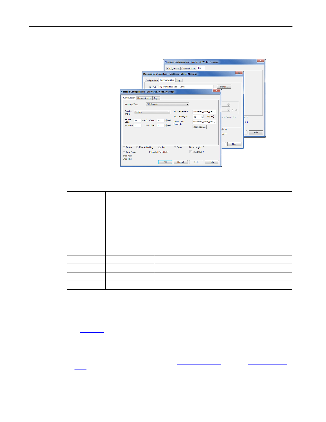
Rockwell Automation Publication 750COM-UM009A-EN-P - May 2017 107
Using Explicit Messaging Chapter 5
Formatting a Message to Write Multiple Parameters
Figure 27 - Scattered Write Multiple Message Configuration Dialog-boxes
The following table identifies the data that is required in each box to configure
a message to write multiple parameters.
Configuration Tab Example Value Description
Message Type
Service Type
(1)
Service Code
(1)
Class
Instance
Attribute
(2)
Source Element
Source Length
Destination
CIP Generic (network)
Custom
4e (hexadecimal)
93 or 9F (hexadecimal)
(4)
0 (Dec.)
0 (hexadecimal)
Scattered_Write_Request
(5)
40-bytes
(5)
Scattered_Write_Response
(6)
Used to access the DPI Parameter Object in the drive.
Required for scattered write messages.
Code for the requested service.
Class ID for the Class ID for the DPI Parameter Object or Host DPI Parameter Object.
Required for scattered write messages.
Required for scattered write messages.
The tag for the request service data.
Number of bytes of request service data.
The tag for the response service data.
Communication Tab Example Value Description
Path
(3)
My_PowerFlex_755T_Drive The path is the route that the message follows.
Tag Tab Example Value Description
Name Scattered_Write_Message The name for the message.
(1) The default setting for Service Type is ‘Custom’, which enables the entry of a Service Code not available from the Service Type pull-down menu. When choosing a Service
Type other than ‘Custom’ from the pull-down menu, the appropriate hexadecimal value is automatically assigned to the Service Code box, which is dimmed
(unavailable). When writing to 32-bit REAL (floating point) parameters, as in this example, data conversion that is using COP (copy) instructions or UDDTs is required to
write the parameter values.
(2) Scattered writes always write parameter values to the nonvolatile storage (NVS) of the drive, which retains these values even after the drive power is cycled. Important:
Be cautious as the NVS can quickly exceed its lifecycle and cause the drive to malfunction.
(3) Click ‘Browse’ to find the path, or type in the name of the device listed in the I/O Configuration folder (for this example, My_PowerFlex_755T_Drive).
(4) See Table 8 on page 96
for limitations of PowerFlex 755T drives when using DPI Parameter Object Class code 0x93 or host DPI Parameter Object Class code 0x9F for
Explicit Messaging.
(5) In this example, we are writing to five 32-bit REAL (floating point) parameters. Each parameter being written to requires two contiguous DINT registers. Therefore, a
controller tag was created with its Data Type field set to the name of the UDDT of five interleaved DINTs and REALs. Also, the Source Length field on the Message
Configuration dialog box must correspond to the selected Data Type in bytes. For this example, 40-bytes for an array of five scattered REAL structures). Scattered write
messages always assume that every parameter being written to is a 32-bit parameter, regardless of its actual size. Maximum message length is 256-bytes, which can
write up to 32 parameters, regardless of their size. For parameter numbers, see DPI Parameter Object on page 145
(Class code 0x93) or Host DPI Parameter Object on
page 163 (Class code 0x9F).
(6) The controller tag for ‘Scattered_Write_Response’ must be the same size as the controller tag for ‘Scattered_Write_Request’ (for this example, 40-bytes). An array of
DINTs is suggested to be able to read any error codes that are returned.
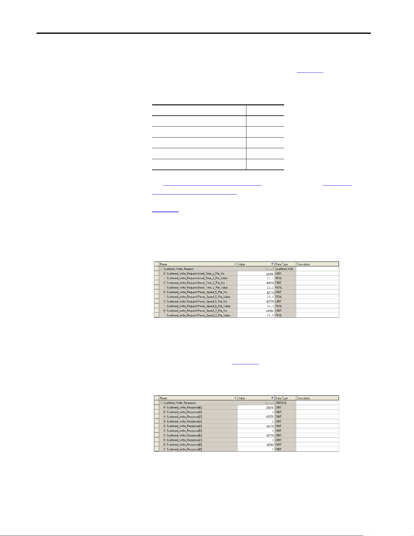
108 Rockwell Automation Publication 750COM-UM009A-EN-P - May 2017
Chapter 5 Using Explicit Messaging
ControlLogix Controller Example Scattered Write Request Data
In this message example, we use the data structure in Figure 28 in the source tag
(Scattered_Write_Request) to write new values to these floating point(32-bit
REAL) parameters. The values are written as Port Number: Parameter
Number - [Parameter Name].
See DPI Parameter Object on page 145
(Class code 0x93) or Host DPI
Parameter Object on page 163 (Class code 0x9F) for parameter numbering.
Figure 28
shows the parameter values which, in this example, have been
converted using a UDDT to write their values. COP (copy) instructions could
have been used for this purpose instead of a UDDT. If the parameters being
written are 32-bit integers, do not COP (copy) the data to a REAL tag.
Figure 28 - Example Scattered Write Request Converted Data
ControlLogix Controller Example Scattered Write Response Data
The results of the message appear in the destination tag named
Scattered_Write_Response (Figure 29
). Values of ‘0’ indicate that no errors
occurred.
Figure 29 - Example Scattered Write Response Data
PowerFlex 755T Drive Parameter Write Value
10:1916 - [VRef Accel Time 2] 11.1 Sec
10:1918 - [VRef Decel Time 2] 22.2 Sec
10:1818 - [Preset Speed 5] 33.3 Hz
10:1819 - [Preset Speed 6] 44.4 Hz
10:1820 - [Preset Speed 7] 55.5 Hz

Rockwell Automation Publication 750COM-UM009A-EN-P - May 2017 109
Using Explicit Messaging Chapter 5
Explanation of Request and Response Data for Scattered Read
Multiple Messaging
The data structures in Tabl e 1 4 and Tab le 15 use 32-bit words and can
accommodate up to 32 parameters in a message. In the Response Message, a
parameter number with Bit 31 set indicates that the associated parameter value
field contains an error code (parameter number in response data is negative).
The PowerFlex drives with TotalFORCE™ Control Programming Manual,
publication 750-PM100
, lists the data type for each parameter. When
performing a Scattered Read of REAL data type parameters, the DINT
parameter value in the Response (Destination Data) array must be COP to a
REAL tag.
Table 14 - Data Structures for Scattered Read Messages
Request (Source Data) Response (Destination Data)
DINT 0 Parameter Number DINT 0 Parameter Number
1 Pad 1 Parameter Value
2 Parameter Number 2 Parameter Number
3 Pad 3 Parameter Value
4 Parameter Number 4 Parameter Number
5 Pad 5 Parameter Value
6 Parameter Number 6 Parameter Number
7 Pad 7 Parameter Value
8 Parameter Number 8 Parameter Number
9 Pad 9 Parameter Value
10 Parameter Number 10 Parameter Number
11 Pad 11 Parameter Value
12 Parameter Number 12 Parameter Number
13 Pad 13 Parameter Value
14 Parameter Number 14 Parameter Number
15 Pad 15 Parameter Value
16 Parameter Number 16 Parameter Number
17 Pad 17 Parameter Value
18 Parameter Number 18 Parameter Number
19 Pad 19 Parameter Value
20 Parameter Number 20 Parameter Number
21 Pad 21 Parameter Value
22 Parameter Number 22 Parameter Number
23 Pad 23 Parameter Value
24 Parameter Number 24 Parameter Number
25 Pad 25 Parameter Value
26 Parameter Number 26 Parameter Number
27 Pad 27 Parameter Value

110 Rockwell Automation Publication 750COM-UM009A-EN-P - May 2017
Chapter 5 Using Explicit Messaging
When performing a Scattered Write to REAL data type parameters, the REAL
parameter value must be COP to the DINT parameter value tag in the Request
(Source Data) array.
28 Parameter Number 28 Parameter Number
29 Pad 29 Parameter Value
30 Parameter Number 30 Parameter Number
31 Pad 31 Parameter Value
32 Parameter Number 32 Parameter Number
33 Pad 33 Parameter Value
34 Parameter Number 34 Parameter Number
35 Pad 35 Parameter Value
...
...
62 Parameter Number 62 Parameter Number
63 Pad 63 Parameter Value
Table 15 - Data Structures for Scattered Write Messages
DINT 0
Request (Source Data)
DINT 0
Response (Destination Data)
Parameter Number Parameter Number
1Parameter Value 1Pad
2 Parameter Number 2 Parameter Number
3Parameter Value 3Pad
4 Parameter Number 4 Parameter Number
5Parameter Value 5Pad
6 Parameter Number 6 Parameter Number
7Parameter Value 7Pad
8 Parameter Number 8 Parameter Number
9Parameter Value 9Pad
10 Parameter Number 10 Parameter Number
11 Parameter Value 11 Pad
12 Parameter Number 12 Parameter Number
13 Parameter Value 13 Pad
14 Parameter Number 14 Parameter Number
15 Parameter Value 15 Pad
16 Parameter Number 16 Parameter Number
17 Parameter Value 17 Pad
18 Parameter Number 18 Parameter Number
19 Parameter Value 19 Pad
20 Parameter Number 20 Parameter Number
21 Parameter Value 21 Pad
22 Parameter Number 22 Parameter Number
23 Parameter Value 23 Pad
24 Parameter Number 24 Parameter Number
25 Parameter Value 25 Pad
26 Parameter Number 26 Parameter Number
27 Parameter Value 27 Pad
Table 14 - Data Structures for Scattered Read Messages (continued)

Rockwell Automation Publication 750COM-UM009A-EN-P - May 2017 111
Using Explicit Messaging Chapter 5
28 Parameter Number 28 Parameter Number
29 Parameter Value 29 Pad
30 Parameter Number 30 Parameter Number
31 Parameter Value 31 Pad
32 Parameter Number 32 Parameter Number
33 Parameter Value 33 Pad
34 Parameter Number 34 Parameter Number
35 Parameter Value 35 Pad
...
...
62 Parameter Number 62 Parameter Number
63 Parameter Value 63 Pad
Table 15 - Data Structures for Scattered Write Messages (continued)

112 Rockwell Automation Publication 750COM-UM009A-EN-P - May 2017
Chapter 5 Using Explicit Messaging
Notes:

Rockwell Automation Publication 750COM-UM009A-EN-P - May 2017 113
Chapter 6
Troubleshooting
This chapter provides information for diagnosing and troubleshooting
potential problems with the interface and network.
Viewing Interface Diagnostic
Items
If you encounter unexpected communication problems, the diagnostic items of
the interface can help you or Rockwell Automation® personnel troubleshoot
the problem. Interface diagnostic items can be viewed with any of these drive
configuration tools:
• PowerFlex® 20-HIM-A6 or 20-HIM-C6S HIM
• Connected Components Workbench™ software, release 10 or later
For details on how to view diagnostic items with the HIM, see the
PowerFlex 20-HIM-A6/-C6S HIM (Human Interface Module) User Manual,
publication 20HIM-UM001
.
Topic Page
Viewing Interface Diagnostic Items 99
Viewing and Clearing Events 101
Drive Status Indicators 116
ENET Status Indicator 117
LNK1 Status Indicator 117
LNK2 Status Indicator 118
Table 16 - Interface Diagnostic Items
No. Name Description
1 Common Logic Cmd The present value of the Common logic command being transmitted to the drive by
this interface.
2 Prod Logic Cmd The present value of the Product logic command being transmitted to the drive by
this interface.
3 Reference The present value of the reference being transmitted to the drive by this interface.
4 Common Logic Sts The present value of the common logic status being received from the drive by this
interface.
5 Prod Logic Sts The present value of the product logic status being received from the drive by this
interface.
6 Feedback The present value of the Feedback being received from the drive by this interface.
7 Input Size The size in bytes of the input image that is transferred from the network to the
drive.
8 Output Size The size in bytes of the output image that is transferred from the drive to the
network.
9 DL Fr Net Avail The number from network datalinks currently available to the interface.

114 Rockwell Automation Publication 750COM-UM009A-EN-P - May 2017
Chapter 6 Troubleshooting
10 DL To Net Avail The number to network datalinks currently available to the interface.
11 DL Fr Net 01 Val The present value of the respective Host DL From Net xx parameter being
transmitted to the drive by this interface. If a datalink is not used, its respective
value is zero.
12 DL Fr Net 02 Val
13 DL Fr Net 03 Val
14 DL Fr Net 04 Val
15 DL Fr Net 05 Val
16 DL Fr Net 06 Val
17 DL Fr Net 07 Val
18 DL Fr Net 08 Val
19 DL Fr Net 09 Val
20 DL Fr Net 10 Val
21 DL Fr Net 11 Val
22 DL Fr Net 12 Val
23 DL Fr Net 13 Val
24 DL Fr Net 14 Val
25 DL Fr Net 15 Val
26 DL Fr Net 16 Val
27 DL To Net 01 Val The present value of the respective Host DL To Net xx parameter being received
from the drive by this interface. If a datalink is not used, its respective value is zero.
28 DL To Net 02 Val
29 DL To Net 03 Val
30 DL To Net 04 Val
31 DL To Net 05 Val
32 DL To Net 06 Val
33 DL To Net 07 Val
34 DL To Net 08 Val
35 DL To Net 09 Val
36 DL To Net 10 Val
37 DL To Net 11 Val
38 DL To Net 12 Val
39 DL To Net 13 Val
40 DL To Net 14 Val
41 DL To Net 15 Val
42 DL To Net 16 Val
Table 16 - Interface Diagnostic Items (continued)
No. Name Description

Rockwell Automation Publication 750COM-UM009A-EN-P - May 2017 115
Troubleshooting Chapter 6
43
44
45
46
47
48
HW Addr 1
HW Addr 2
HW Addr 3
HW Addr 4
HW Addr 5
HW Addr 6
Decimal value of each byte in the Ethernet hardware (MAC) address of the
interface.
49
50
51
52
IP Addr Act 1
IP Addr Act 2
IP Addr Act 3
IP Addr Act 4
Value of each byte in the present IP address of the interface. A value of ‘0’ appears
if the interface does not currently have an IP address.
53
54
55
56
Subnet Act 1
Subnet Act 2
Subnet Act 3
Subnet Act 4
Value of each byte in the present subnet mask of the interface. A value of '0'
appears if the interface does not currently have a subnet mask.
57
58
59
60
Gateway Act 1
Gateway Act 2
Gateway Act 3
Gateway Act 4
Value of each byte in the present gateway address of the interface. A value of '0'
appears if the interface does not currently have a gateway address.
61 Net Rx Rate The number of Ethernet packets that are received per second.
62 Net Rx Overruns The number of receive buffer overruns that the Ethernet hardware has reported.
63 Net Rx Packets The number of Ethernet packets that the interface has received.
64 Net Rx Errors The number of received errors reported by the Ethernet hardware.
65 Net Tx Packets The number of Ethernet packets that the interface has transmitted.
66 Net Tx Errors The number of transmit errors reported by the Ethernet hardware.
67 Missed I/O Pkts The number of incoming I/O connection packets that the interface did not receive.
Table 16 - Interface Diagnostic Items (continued)
No. Name Description
255:255:255:255:255:255
[HW Addr 1]
[HW Addr 2]
[HW Addr 3]
[HW Addr 4]
HW Addr 5]
[HW Addr 6]
255.255.255.255
[IP Addr Act 1]
[IP Addr Act 2]
[IP Addr Act 3]
[IP Addr Act 4]
255.255.255.255
[Subnet Act 1]
[Subnet Act 2]
[Subnet Act 3]
[Subnet Act 4]
255.255.255.255
[Gateway Act 1]
[Gateway Act 2]
[Gateway Act 3]
[Gateway Act 4]

116 Rockwell Automation Publication 750COM-UM009A-EN-P - May 2017
Chapter 6 Troubleshooting
Viewing and Clearing Events
The interface has an event queue to record significant events that occur in the
operation of the interface. When such an event occurs, an entry consisting of
the numeric code of the event and a time stamp is put into the event queue. You
can view the event queue using CCW. The event queue cannot be viewed using
the HIM.
The event queue can contain up to 100 entries, which are stored in nonvolatile
storage (NVS). Eventually the event queue becomes full, since its contents are
retained through power cycles and resets. At that point, a new entry replaces
the oldest entry. Only an event queue clear operation clears the event queue
contents.
Many events in the event queue occur under normal operation. If you
encounter unexpected communication problems, the events can help you or
Allen-Bradley® personnel troubleshoot the problem. The following events can
appear in the event queue.
68 Net Addr Sw The present value of the interface node address (rotary) switches.
69 MDIX Status Indicates the type of cable that is connected to the interface ports.
P1 = ENET1 network port and P2 = ENET2 network port.
Bit 0 - P1 Normal
Bit 1 - P1 Swapped
Bit 2 - P2 Normal
Bit 3 - P2 Swapped
70 Net Heap Avail The amount of data memory available to the network communication firmware
for dynamic (runtime) memory allocations.
Table 16 - Interface Diagnostic Items (continued)
No. Name Description
Table 17 - Interface Diagnostic Items
Code Event Description
350 Net LNK1 Up The interface established a network link on its ENET1
network port.
351 Net LNK1 Down The interface lost the network link on its ENET1 network
port.
352 Net LNK2 Up The interface established a network link on its ENET2
network port.
353 Net LNK2 Down The interface lost the network link on its ENET2 network
port.
354 Net Dup Address Another device having the same IP address as the
interface was detected on the network.
355 Invalid Net Cfg The interface network address configuration parameters
are invalid, or the network address that is provided by
the BOOTP or DHCP server is invalid.
356 BOOTP Response The interface received a response to its BOOTP request.
357 DHCP Response The interface received a response to its DHCP request.
358 DHCP Renew The interface renewed its network address lease with
the DHCP Server.

Rockwell Automation Publication 750COM-UM009A-EN-P - May 2017 117
Troubleshooting Chapter 6
359 DHCP Rebind The interface rebinded its network address lease with
the DHCP Server.
360 DHCP Release The interface network address lease expired.
361 Net Sent Reset The interface received a reset command from the
network.
362 Net I/O Open The I/O connection from the network to the interface has
been opened.
363 Net I/O Idle The interface received I/O connection ‘idle’ packets from
the network.
364 Net I/O Close The I/O connection from the network to the interface
was closed.
365 Net I/O Timeout The interface I/O connection has timed out.
366 Net I/O Abort The interface I/O connection was aborted because the
datalink configuration was changed.
367 PCCC I/O Open The interface began receiving PCCC control messages
after the PCCC Control Timeout was set to a nonzero
value.
368 PCCC I/O Close The device that sends PCCC control messages to the
interface (for example, the Control Bar feature in CCW)
has set the PCCC Control Timeout to zero.
369 PCCC I/O Timeout The interface has not received a PCCC control message
before the PCCC Control Timeout.
370 Msg Ctrl Open The timeout attribute in the CIP-based network
Assembly Object was set to a nonzero value. This allows
control messages to be sent to the interface via the CIP-
based network Assembly Object.
371 Msg Ctrl Close The timeout attribute in the CIP-based network
Assembly Object was set to zero, disallowing control
messages to be sent to the interface via the CIP-based
network Assembly Object.
372 Msg Ctrl Timeout The interface has not received a control message via the
CIP-based network Assembly Object before the object
timeout attribute triggered.
375 Net Ring Up The Device Level Ring (DLR) status is Normal.
376 Net Ring Down The Device Level Ring (DLR) status is Faulted.
Table 17 - Interface Diagnostic Items (continued)
Code Event Description
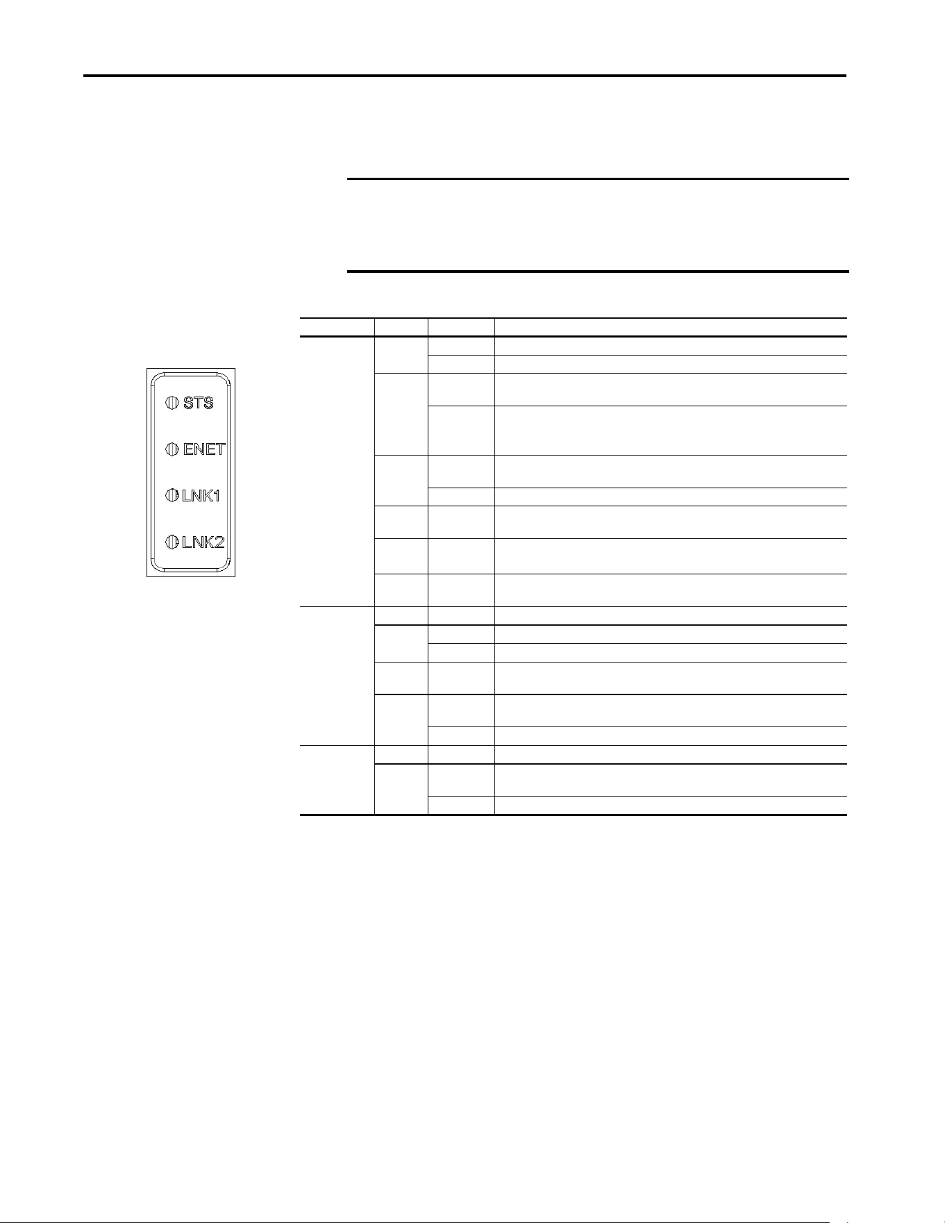
118 Rockwell Automation Publication 750COM-UM009A-EN-P - May 2017
Chapter 6 Troubleshooting
Drive Status Indicators
The condition or state of the drive is constantly monitored and is indicated
through the status indicators and/or the HIM (if present).
Table 18 - PowerFlex 755T Drive Status Indicator Descriptions
IMPORTANT The Status Indicator light-emitting diodes on the HIM cradle do not indicate
the status of an installed communication interface option. If an optional
communication interface is installed, refer to that user manual for a
description of status indicator location and indications.
Name Color State Description
STS
(Status)
Green Flashing Drive ready but not running, and no faults are present.
Steady Drive running, no faults are present.
Yellow Flashing Drive is not running, a type 2 (non-configurable) alarm condition exists and the
drive cannot be started. See 10:467 - [Type 2 Alarms]
(1)
.
Steady Drive is not running, a type 1 (configurable) alarm condition exists and the drive
continues to run.
See 10:465 - [Alarm Status A] and 10:466 - [Alarm Status B]
(1)
.
Red Flashing A major fault has occurred. Drive stops. Drive cannot be started until fault
condition is cleared. See 0:610- [Last Fault Code]
(1)
.
Steady A non-resettable fault has occurred.
Red /
Yellow
Flashing
Alternately
A minor fault has occurred. When running, the drive continues to run. System is
brought to a stop under system control. Fault must be cleared to continue.
Yellow /
Green
Flashing
Alternately
When running, a type 1 alarm exists.
See 10:465 - [Alarm Status A] and 10:466 - [Alarm Status B]
(1)
.
Green /
Red
Flashing
Alternately
Drive is flash updating.
ENET Unlit Off The interface is not properly connected to the network or needs an IP Address.
Red Flashing An EtherNet/IP connection has timed out.
Steady The interface failed the duplicate IP Address detection test.
Red /
Green
Flashing
Alternately
The interface is performing a self-test.
Green Flashing The interface is properly connected but is not communicating with any devices
on the network.
Steady The interface is properly connected and communicating on the network.
LNK 1
LNK 2
Unlit Off The interface is not powered or is not transmitting on the network.
Green Flashing The interface is properly connected and transmitting data packets on the
network.
Steady The interface is properly connected but is not transmitting on the network.
(1) See the PowerFlex 755T Programming Manual, publication 750-RM002, for information about this parameter.

Rockwell Automation Publication 750COM-UM009A-EN-P - May 2017 119
Troubleshooting Chapter 6
ENET Status Indicator
LNK1 Status Indicator
Table 19 - ENET Status Indicator Description
Status Cause Corrective Action
Off The interface is not powered, the interface is not properly connected
to the network, or the interface needs an IP Address.
• Apply power to the drive.
• Securely connect the interface to the network by using an
Ethernet cable.
• Set a unique IP Address by using the rotary switches, a BOOTP
server, a DHCP server, or by using interface parameters.
Flashes Red • The I/O connection has timed out.
• Explicit messaging control has timed out.
• The rotary switches have been changed since power up.
• The network configuration (IP Address, subnet mask, gateway
address) is invalid.
• Re-establish the I/O connection with the controller.
• Check the amount of traffic on the network.
• If the I/O connection is multicast, check the IGMP Snooping
settings on the Ethernet switch.
• Re-establish explicit messaging control with a network client (for
example, enable the Control Bar feature in CCW).
• Cycle power to recognize the new rotary switch settings.
• Write valid values to the interface [IP Addr Cfg x], [Subnet Cfg x],
and [Gateway Cfg x] parameters and cycle power.
Steady Red • Rotary switches are set to a reserved value (0, 255...998).
• A duplicate IP Address was detected.
• The DHCP lease has expired.
• Set the rotary switches to a non-reserved value (1 ... 254, 999).
• Configure the interface to use a unique IP Address and cycle
power.
• Configure the DHCP server to provide longer or infinite leases.
Flashes Green The interface is operating normally but the I/O connection is not
running and explicit messaging control is not active.
• Place the controller in RUN mode.
• Program the controller to recognize and transmit I/O to the
interface.
• Configure the interface for the program in the controller.
• Normal behavior if no I/O is being transferred.
Steady Green The interface is operating normally and the I/O connection is running
or explicit messaging control is active.
No action required.
Table 20 - LNK1 Status Indicator Descriptions
Status Cause Corrective Action
Off The interface is not properly connected to the network. Securely connect the interface to the network by using an Ethernet
cable. Also, make sure that the Ethernet cable is correctly connected
to the Ethernet connector.
Steady Green The ENET1 network port has a 100 Mbps network link, but no
activity.
No action required.
Flashes Green The ENET1 network port has a 100 Mbps network link with activity. No action required.
Steady Yellow The ENET1 network port has a 10 Mbps network link, but no activity. No action required.
Flashes Yellow The ENET1 network port has a 10 Mbps network link with activity. No action required.

120 Rockwell Automation Publication 750COM-UM009A-EN-P - May 2017
Chapter 6 Troubleshooting
LNK2 Status Indicator
Table 21 - LNK2 Status Indicator Descriptions
Status Cause Corrective Action
Off The interface is not properly connected to the network. Securely connect the interface to the network by using an Ethernet
cable. Also, make sure that the Ethernet cable is correctly connected
to the Ethernet connector.
Steady Green The ENET2 network port has a 100 Mbps network link, but no
activity.
No action required.
Flashes Green The ENET2 network port has a 100 Mbps network link with activity. No action required.
Steady Yellow The ENET2 network port has a 10 Mbps network link, but no activity. No action required.
Flashes Yellow The ENET2 network port has a 10 Mbps network link with activity. No action required.
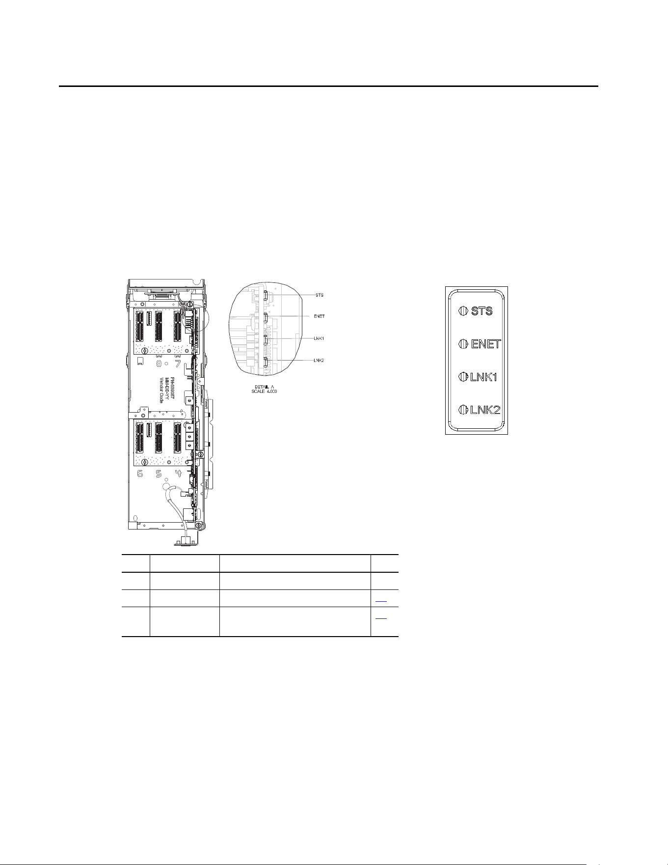
Rockwell Automation Publication 750COM-UM009A-EN-P - May 2017 121
Appendix A
Status Indicators
Understanding the Status
Indicators
The interface has four status indicators. They can be viewed with the drive
HIM bezel closed or open.
Item Indicator Name Description Page
1STS Drive Status --
2 ENET EtherNet/IP Connection Status 122
3LNK1
LNK2
EtherNet/IP Link and Activity Status 123
Built-in EtherNet/IP interface indicators are on
main control board in drive control pod
Indicators that are shown with HIM
bezel closed and drive cover installed

122 Rockwell Automation Publication 750COM-UM009A-EN-P - May 2017
Appendix A Status Indicators
ENET Status Indicator
This red/green bicolor status indicator shows the status of the network
connection for the interface, as shown in the following table.
Table 22 - ENET Status Indicators
Status Cause Corrective Actions
Off The interface is not powered, the
interface is not properly connected to
the network, or the interface needs an
IP address.
• Apply power to the drive.
• Securely connect the interface to the network by
using an Ethernet cable.
• Set a unique IP address by using the rotary
switches, a BOOTP server, a DHCP server, or by using
interface parameters.
Steady Red • Rotary switches are set to a
reserved value (0, 255...998).
• A duplicate IP address was
detected.
• The DHCP lease has expired.
• Set the rotary switches to a non-reserved value
(1...254, 999).
• Configure the interface to use a unique IP address
and cycle power.
• Configure the DHCP server to provide longer or
infinite leases.
Flashing Red • The I/O connection has timed out.
• Explicit Messaging control has
timed out.
• The rotary switches have been
changed since power up.
• The network configuration (IP
address, subnet mask, gateway
address) is invalid.
• Re-establish the I/O connection with the controller.
• Check the amount of traffic on the network.
• If the I/O connection is multicast, check the IGMP
Snooping settings on the Ethernet switch.
• Re-establish Explicit Messaging control with a
network client (for example, enable the Control Bar
feature in CCW).
• Cycle power to recognize the new rotary switch
settings.
• Write valid values to the interface [IP Addr Cfg x],
[Subnet Cfg x], and [Gateway Cfg x] parameters
and cycle power.
Flashing Red/
Green
The interface is performing a self-test. No action is required.
Flashing Green The interface is operating normally but
the I/O connection is not running and
Explicit Messaging control is not active.
• Place the controller in RUN mode.
• Program the controller to recognize and transmit
I/O to the interface.
• Configure the interface for the program in the
controller.
•Normal behavior if no I/O is being transferred.
Steady Green The interface is operating normally and
the I/O connection is running or Explicit
Messaging control is active.
No action is required.

Rockwell Automation Publication 750COM-UM009A-EN-P - May 2017 123
Status Indicators Appendix A
LINK Status Indicators
These green status indicators show the status of the individual Ethernet
connectors for the adapter that transmit or receive data on the network as
shown in the following tables.
Table 23 - LNK1 Status Indicator
Status Cause Corrective Actions
Off The adapter is not properly connected
to the network.
Securely connect the adapter to the network by using
an Ethernet cable. Also, make sure that the Ethernet
cable is correctly connected to the Ethernet connector.
Steady Green The ENET1 network port has a 100
Mbps network link, but no activity.
No action required.
Flashes Green The ENET1 network port has a 100
Mbps network link with activity.
No action required.
Steady Yellow The ENET1 network port has a 10 Mbps
network link, but no activity.
No action required.
Flashes Yellow The ENET1 network port has a 10 Mbps
network link with activity.
No action required.
Table 24 - LNK2 Status Indicator
Status Cause Corrective Action
Off The adapter is not properly connected
to the network.
Securely connect the adapter to the network by using
an Ethernet cable. Also, make sure that the Ethernet
cable is correctly connected to the Ethernet connector.
Steady Green The ENET2 network port has a 100
Mbps network link, but no activity.
No action required.
Flashes Green The ENET2 network port has a 100
Mbps network link with activity.
No action required.
Steady Yellow The ENET2 network port has a 10 Mbps
network link, but no activity.
No action required.
Flashes Yellow The ENET2 network port has a 10 Mbps
network link with activity.
No action required.

124 Rockwell Automation Publication 750COM-UM009A-EN-P - May 2017
Appendix A Status Indicators
Notes:

Rockwell Automation Publication 750COM-UM009A-EN-P - May 2017 125
Appendix B
Specifications
This appendix presents the specifications for the adapter.
Communication
Regulatory Compliance
Network
Protocol
Data Rates
EtherNet/IP network
10 Mbps full-duplex, 10 Mbps half-duplex, 100 Mbps full-duplex, or 100
Mbps half-duplex
Connection Limits 30 TCP connections
16 simultaneous CIP-based network explicit connections plus one exclusive
owner I/O connection.
Class 1 I/O connections (for example, from a ControlLogix® controller)
uses an exclusive-owner I/O connection.
Explicit Messaging when ‘connected’ is chosen (for example, in a checkbox in
RSLogix 5000® software) uses a CIP-based network explicit connection.
Explicit Messaging where the ‘connected’ option is not chosen, does not use
a CIP-based network explicit connection.
Requested Packet Interval (RPI) 2 ms minimum
Packet Rate At least 1000 total packets per second (500 in and 500 out)
UL UL508C
cUL CAN / CSA C22.2 No. 14-M91
CE EN50178 and EN61800-3
CTick EN61800-3
IMPORTANT This product is a category C2 product according to IEC 61800-3. In a domestic
environment, this product causes radio interference, in which case
supplementary mitigation measures can be required.

126 Rockwell Automation Publication 750COM-UM009A-EN-P - May 2017
Appendix B Specifications
Notes:

Rockwell Automation Publication 750COM-UM009A-EN-P - May 2017 127
Appendix C
Interface Parameters
This appendix provides information about the interface parameters.
How Parameters Are
Organized
The built-in EtherNet/IP interface parameters are numbered consecutively
and displayed in a Numbered List or File-Group view order.
You can view the interface parameters with any of the following drive
configuration tools:
• PowerFlex® 20-HIM-A6 or 20-HIM-C6S HIM - use the or
key to scroll to the PowerFlex 755T. Press the (Folders) key, and use
the or key to scroll to the DEV PARAM folder.
• Connected Components Workbench™ software—click Parameters.
Select 0 - PowerFlex 755T from the port pull-down list.
Topic Page
How Parameters Are Organized 127
Parameter List 128
128 Rockwell Automation Publication 750COM-UM009A-EN-P - May 2017
Appendix C Interface Parameters
Parameter List
Icon Descriptions
This icon indicates that the parameter value cannot be changed until the drive is stopped.
This icon indicates that the parameter cannot be set to DataLink In.
This icon indicates that an explicit message write cannot change the parameter value. The parameter value can be changed by using a datalink.
Table 25 - Port 0: Parameter List
No. Display Name
Extended Name
Description
Values
Read-Write
Data Type
Parameter 30
[Access Level]
300 Net Addr Sel
Network Address Selection
Selects the source for the interface node address, subnet mask, and gateway address
when the rotary switches on the main control board are set to 999.
‘Parameters’ (1) – The address comes from parameters 302
[IP Addr Cfg 1]…313
[Gateway Cfg 4].
‘BOOTP’ (2) – The address comes from a BOOTP server on the network.
‘DHCP’ (3) – The address comes from a DHCP server on the network, this could be a
Stratix® switch.
A power cycle or reset is needed for changes to this parameter to take effect.
Default:
Options:
3 = ‘DHCP’
1 = ‘Parameters’
2 = ‘BOOTP’
3 = ‘DHCP’
RW 32-bit
Integer
0
301 Net Addr Src
Network Address Source
Displays the active source for the interface node address, subnet mask, and gateway
address.
‘Switches’ (0) – The address comes from the rotary switches on the main control board.
‘Parameters’ (1) – The address comes from parameters 302
[IP Addr Cfg 1]…313
[Gateway Cfg 4].
‘BOOTP’ (2) – The address comes from a BOOTP server on the network.
‘DHCP’ (3) – The address comes from a DHCP server on the network, this could be a
Stratix switch.
Default:
Options:
0 = ‘Switches’
0 = ‘Switches’
1 = ‘Parameters’
2 = ‘BOOTP’
3 = ‘DHCP’
RO 32-bit
Integer
0
302
303
304
305
IP Addr Cfg 1
IP Addr Cfg 2
IP Addr Cfg 3
IP Addr Cfg 4
IP Address Configuration n
Sets the first, second, third, and fourth byte in the IP address when parameter 301
[Net
Addr Src] is set to 1 ‘Parameters’.
A power cycle or reset is needed for changes to this parameter to take effect.
Default:
Min/Max:
0
0/255
RW 32-bit
Integer
0
306
307
308
309
Subnet Cfg 1
Subnet Cfg 2
Subnet Cfg 3
Subnet Cfg 4
Subnet Configuration n
Sets the first, second, third, and fourth byte in the subnet mask when parameter 301
[Net Addr Src] is set to 1 ‘Parameters’. The subnet mask cannot be 0.0.0.0.
A power cycle or reset is needed for changes to this parameter to take effect.
Default:
Min/Max:
0
0/255
RW 32-bit
Integer
0

Rockwell Automation Publication 750COM-UM009A-EN-P - May 2017 129
Interface Parameters Appendix C
310
311
312
313
Gateway Cfg 1
Gateway Cfg 2
Gateway Cfg 3
Gateway Cfg 4
Gateway Configuration n
Sets the first, second, third, and fourth byte in the gateway address when parameter 301
[Net Addr Src] is set to 1 ‘Parameters’. If the gateway address is 0.0.0.0, the PowerFlex
755T can only communicate with devices on the same subnet as the drive. It is not able
to communicate with devices on other subnets.
If the gateway address is not set to 0.0.0.0, then it must be set to an address that is on
the same subnet as the drive's IP address.
A power cycle or reset is needed for changes to this parameter to take effect.
Default:
Min/Max:
0
0/255
RW 32-bit
Integer
0
314 Net Rate Cfg 1
Net Rate Configuration 1
Sets the speed and duplex at which the interface communicates on its ENET n network
port.
A power cycle or reset is needed for changes to this parameter to take effect. Updates
0:315 - [Net Rate Act 1]
Default:
Options:
0 = ‘Autodetect’
0 = ‘Autodetect’
1 = ‘10 Mbps Full’
2 = ‘10 Mbps Half’
3 = ‘100 Mbps Full’
4 = ‘100 Mbps Half’
RW 32-bit
Integer
0
315 Net Rate Act 1
Network Rate Actual 1
Displays the active network data rate at which interface n communicates.
Default:
Options:
0 = ‘No Link’
0 = ‘No Link’
1 = ‘10 Mbps Full’
2 = ‘10 Mbps Half’
3 = ‘100 Mbps Full’
4 = ‘100 Mbps Half’
5 = ‘Dup IP Addr’
RO 32-bit
Integer
0
316 Net Rate Cfg 2
Net Rate Configuration 2
Sets the speed and duplex at which the interface communicates on its ENET n network
port.
A power cycle or reset is needed for changes to this parameter to take effect. Updates
0:317 - [Net Rate Act 2]
Default:
Options:
0 = ‘Autodetect’
0 = ‘Autodetect’
1 = ‘10 Mbps Full’
2 = ‘10 Mbps Half’
3 = ‘100 Mbps Full’
4 = ‘100 Mbps Half’
RW 32-bit
Integer
0
317 Net Rate Act 2
Network Rate Actual 2
Displays the active network data rate at which interface n communicates.
Default:
Options:
0 = ‘No Link’
0 = ‘No Link’
1 = ‘10 Mbps Full’
2 = ‘10 Mbps Half’
3 = ‘100 Mbps Full’
4 = ‘100 Mbps Half’
5 = ‘Dup IP Addr’
RO 32-bit
Integer
0
Table 25 - Port 0: Parameter List (continued)
No. Display Name
Extended Name
Description
Values
Read-Write
Data Type
Parameter 30
[Access Level]

130 Rockwell Automation Publication 750COM-UM009A-EN-P - May 2017
Appendix C Interface Parameters
321
322
323
324
325
326
327
328
329
330
331
332
333
334
335
336
DL From Net 01
DL From Net 02
DL From Net 03
DL From Net 04
DL From Net 05
DL From Net 06
DL From Net 07
DL From Net 08
DL From Net 09
DL From Net 10
DL From Net 11
DL From Net 12
DL From Net 13
DL From Net 14
DL From Net 15
DL From Net 16
Datalink From Network n
Select a parameter that consumes data, which the datalink nn in the embedded interface
produces.
Default:
Min/Max:
0
0/159999
RW 32-bit
Integer
0
340
341
342
343
344
345
346
347
348
349
350
351
352
353
354
355
DL To Net 01
DL To Net 02
DL To Net 03
DL To Net 04
DL To Net 05
DL To Net 06
DL To Net 07
DL To Net 08
DL To Net 09
DL To Net 10
DL To Net 11
DL To Net 12
DL To Net 13
DL To Net 14
DL To Net 15
DL To Net 16
Datalink To Network n
Select a parameter that produces data, to be consumed by datalink nn in the embedded
interface.
Default:
Min/Max:
0
0/159999
RW 32-bit
Integer
0
356 DLs From Net Act
Datalinks From Network Actual
Displays the number of actual controller-to-drive datalinks being used based on the I/O
connection opened by the controller.
Default:
Min/Max:
0
0/16
RO 32-bit
Integer
0
357 DLs To Net Act
Datalinks To Network Actual
Displays the number of actual drive-to-controller datalinks being used based on the I/O
connection opened by the controller.
Default:
Min/Max:
0
0/16
RO 32-bit
Integer
0
Table 25 - Port 0: Parameter List (continued)
No. Display Name
Extended Name
Description
Values
Read-Write
Data Type
Parameter 30
[Access Level]
Rockwell Automation Publication 750COM-UM009A-EN-P - May 2017 131
Interface Parameters Appendix C
360 Comm Flt Action
Communication Fault Action
Sets the action that the communication interface and drive take when I/O
communication is disrupted. When communication is re-established, the drive
automatically receives the logic command, reference, and datalinks over the network
again.
‘Fault’ (0) – The response is a major fault. The drive stops modulating, the motor coasts
to a stop, and a fault reset is required to resume operation.
‘Stop’ (1) – The response is to stop in the way set by the active stop mode.
‘Zero Data’ (2) – The response is to continue operating, but to put zeros in the logic
command, reference, and datalinks.
‘Hold Last’ (3) – The response is to continue operating, and to use the last values in the
logic command, reference, and datalinks.
‘Send Flt Cfg’ (4) – The response is to continue operating, but to use the logic command
that is specified in parameter 365
[Flt Cfg Logic] and the reference that is specified in 365
[Flt Cfg Ref]. The drive also uses the values in parameters 370 [Flt Cfg DL 01]… 385 [Flt
Cfg DL 16] in the parameters consuming data from those datalinks
Default:
Options:
0 = ‘Fault’
0 = ‘Fault’
1 = ‘Stop’
2 = ‘Zero Data’
3 = ‘Hold Last’
4 = ‘Send Flt Cfg’
RW 32-bit
Integer
0
361 Idle Flt Action
Idle Fault Action
Sets the action that the communication interface and drive take when the controller
leaves the run mode (faulted or in program mode). When the controller returns to the
Run mode, the drive automatically receives the logic command, reference, and datalinks
over the network again.
‘Fault’ (0) – The response is a major fault. The drive stops modulating, the motor coasts
to a stop, and a fault reset is required to resume operation.
‘Stop’ (1) – The response is to stop in the way set by the active stop mode.
‘Zero Data’ (2) – The response is to continue operating, but to put zeros in the logic
command, reference, and datalinks.
‘Hold Last’ (3) – The response is to continue operating, and to use the last values in the
logic command, reference, and datalinks.
‘Send Flt Cfg’ (4) – The response is to continue operating, but to use the logic command
that is specified in parameter 364
[Flt Cfg Logic] and the reference that is specified in 365
[Flt Cfg Ref]. The drive also uses the values in parameters 370 [Flt Cfg DL 01]…385 [Flt
Cfg DL 16] in the parameters consuming data from those datalinks
Default:
Options:
0 = ‘Fault’
0 = ‘Fault’
1 = ‘Stop’
2 = ‘Zero Data’
3 = ‘Hold Last’
4 = ‘Send Flt Cfg’
RW 32-bit
Integer
0
Table 25 - Port 0: Parameter List (continued)
No. Display Name
Extended Name
Description
Values
Read-Write
Data Type
Parameter 30
[Access Level]
ATTENTION: Take precautions to help maintain that the setting of this parameter does not create a risk of injury or equipment damage. When
commissioning the drive, verify that your system responds correctly to various situations (for example, a disconnected cable).
ATTENTION: Take precautions to help maintain that the setting of this parameter does not create a risk of injury or equipment damage. When
commissioning the drive, verify that your system responds correctly to various situations (for example, place the controller in program mode).
132 Rockwell Automation Publication 750COM-UM009A-EN-P - May 2017
Appendix C Interface Parameters
363 Msg Flt Action
Message Fault Action
Sets the action that the interface and drive take when explicit messaging control (only
via PCCC or the CIP Assembly Object) is disrupted. When explicit messaging control is re-
established, the drive automatically receives the logic command, reference, and
datalinks over the network again.
‘Fault’ (0) – The response is a major fault. The drive stops modulating, the motor coasts
to a stop, and a fault reset is required to resume operation.
‘Stop’ (1) – The response is to stop in the way set by the active stop mode.
‘Zero Data’ (2) – The response is to continue operating, but to put zeros in the logic
command, reference, and datalinks.
‘Hold Last’ (3) – The response is to continue operating, and to use the last values in the
logic command, reference, and datalinks.
‘Send Flt Cfg’ (4) – The response is to continue operating, but to use the logic command
that is specified in parameter 364
[Flt Cfg Logic] and the reference that is specified in 365
[Flt Cfg Ref]. The drive also uses the values in parameters 370 [Flt Cfg DL 01]… 385 [Flt
Cfg DL 16] in the parameters consuming data from those datalinks.
Default:
Options:
0 = ‘Fault’
0 = ‘Fault’
1 = ‘Stop’
2 = ‘Zero Data’
3 = ‘Hold Last’
4 = ‘Send Flt Cfg’
RW 32-bit
Integer
0
364 Flt Cfg Logic
Fault Configuration Logic
RW Bit 0
Set the logic command for the drive if any of the following is true:
360
[Comm Flt Action] is set to 4 ‘Send Flt Cfg’ and I/O communication are disrupted.
361
[Idle Flt Action] is set to 4 ‘Send Flt Cfg’ and the controller leaves the run mode.
362 [Peer Flt Action] is set to 4 ‘Send Flt Cfg’ and Peer I/O communication are disrupted.
363 [Msg Flt Action] is set to 4 ‘Send Flt Cfg’ and Explicit Messaging for drive control is disrupted.
Note: The first bit table is for systems that contain both an inverter and a converter or only an inverter. The second bit table is for systems that contain ONLY a converter.
Table 25 - Port 0: Parameter List (continued)
No. Display Name
Extended Name
Description
Values
Read-Write
Data Type
Parameter 30
[Access Level]
ATTENTION: Take precautions to help maintain that the setting of this parameter does not create a risk of injury or equipment damage. When
commissioning the drive, verify that your system responds correctly to various situations (for example, a disconnected cable).
Options
Reserved
Reserved
Reserved
Reserved
Reserved
Reserved
Reserved
Reserved
Reserved
Reserved
Reserved
Reserved
Jog 2
Run
Climit Stop
Coast Stop
Reserved
SpdRef Sel 2
SpdRef Sel 1
SpdRef Sel 0
Decel Time 2
Decel Time 1
Accel Time 2
Accel Time1
Reserved
Manual
Reverse
Forward
Clear Faults
Jog 1
Start
Stop
Default00000000000000000000000000000000
Bit 313029282726252423222120191817161514131211109876543210
Options
Reserved
Reserved
Reserved
Reserved
Reserved
Reserved
Reserved
Reserved
Reserved
Reserved
Reserved
Reserved
Reserved
Run
Reserved
Reserved
Reserved
Reserved
Reserved
Reserved
Reserved
Reserved
Reserved
Reserved
Reserved
Reserved
Reserved
Reserved
Clear Faults
Reserved
Start
Stop
Default00000000000000000000000000000000
Bit 313029282726252423222120191817161514131211109876543210

Rockwell Automation Publication 750COM-UM009A-EN-P - May 2017 133
Interface Parameters Appendix C
365 Flt Cfg Ref
Fault Configuration Reference
Set the reference for the drive if any of the following is true:
360
[Comm Flt Action] is set to 4 ‘Send Flt Cfg’ and I/O communication are disrupted.
361 [Idle Flt Action] is set to 4 ‘Send Flt Cfg’ and the controller leaves the run mode.
362 [Peer Flt Action] is set to 4 ‘Send Flt Cfg’ and Peer I/O communication are disrupted.
363
[Msg Flt Action] is set to 4 ‘Send Flt Cfg’ and Explicit Messaging for drive control is
disrupted.
Default:
Min/Max:
0
-220000000/+220000000
RW Real 0
370
371
372
373
374
375
376
377
378
379
380
381
382
383
384
385
Flt Cfg DL 01
Flt Cfg DL 02
Flt Cfg DL 03
Flt Cfg DL 04
Flt Cfg DL 05
Flt Cfg DL 06
Flt Cfg DL 07
Flt Cfg DL 08
Flt Cfg DL 09
Flt Cfg DL 10
Flt Cfg DL 11
Flt Cfg DL 12
Flt Cfg DL 13
Flt Cfg DL 14
Flt Cfg DL 15
Flt Cfg DL 16
Fault Configuration Datalink nn
Set the data for the parameter consuming data from datalink nn if any of the following is
true:
360
[Comm Flt Action] is set to 4 ‘Send Flt Cfg’ and I/O communication are disrupted.
361
[Idle Flt Action] is set to 4 ‘Send Flt Cfg’ and the controller leaves the run mode.
362 [Peer Flt Action] is set to 4 ‘Send Flt Cfg’ and Peer I/O communication are disrupted.
363 [Msg Flt Action] is set to 4 ‘Send Flt Cfg’ and Explicit Messaging for drive control is
disrupted.
Default:
Min/Max:
0
0/4294967295
RW 32-bit
Integer
0
Table 25 - Port 0: Parameter List (continued)
No. Display Name
Extended Name
Description
Values
Read-Write
Data Type
Parameter 30
[Access Level]

134 Rockwell Automation Publication 750COM-UM009A-EN-P - May 2017
Appendix C Interface Parameters
Notes:

Rockwell Automation Publication 750COM-UM009A-EN-P - May 2017 135
Appendix D
EtherNet/IP Objects
This appendix presents information about the EtherNet/IP objects that can be
accessed using explicit messages.
For information on the format of explicit
messages and example ladder logic programs, see Chapter 5
, Using Explicit
Messaging.
Supported Data Types
Object Class Code Page Object Class Code Page
Hex. Dec. Hex. Dec.
Identity Object 0x01 1 136 DPI Alarm Object 0x98 152 156
Assembly Object 0x04 4 137 DPI Diagnostic Object 0x99 153 158
PCCC Object 0x67 103 138 DPI Time Object 0x9B 155 159
DPI Device Object 0x92 146 142 Host DPI Parameter Object 0x9F 159 163
DPI Parameter Object 0x93 147 145 TCP/IP Interface Object 0xF5 245 171
DPI Fault Object 0x97 151 154 Ethernet Link Object 0xF6 246 173
TIP See the EtherNet/IP specification for more information about EtherNet/IP
objects. Information about the EtherNet/IP specification is available on the
ODVA website (http://www.odva.org
).
Table 26 - Supported Data Types
Data Type Description
BOOL 8-bit value -- low bit is true or false
BOOL[x] Array of n bits
CONTAINER 32-bit parameter value - sign that is extended if necessary
DINT 32-bit signed integer
INT 16-bit signed integer
LWORD 64-bit unsigned integer
REAL 32-bit floating point
SHORT_STRING Struct of: USINT length indicator (L); USINT[L] characters
SINT 8-bit signed integer
STRINGN Struct of: UINT character length indicator (W); UINT length indicator (L); USINT[W x L] string data
STRING[x] Array of n characters
STRUCT Structure name only - no size and elements
TCHAR 8-bit or 16-bit character

136 Rockwell Automation Publication 750COM-UM009A-EN-P - May 2017
Appendix D EtherNet/IP Objects
Identity Object
The number of instances depends on the number of components in the
device that is connected to the interface. This number of components
can be read in Instance 0, Attribute 2.
I
UDINT 32-bit unsigned integer
UINT 16-bit unsigned integer
USINT 8-bit unsigned integer
Table 26 - Supported Data Types (continued)
Data Type Description
Table 27 - Identity Object: Class Code
Hexadecimal Decimal
0x01 1
Table 28 - Identity Object: Services
Implemented for
Service Code Class Instance Service Name
0x05 No Yes Reset
0x0E Yes Yes Get_Attribute_Single
0x01 Yes Yes Get_Attributes_All
Table 29 - Identity Object: Instances
Instance Description
0Class
1 Host
2…15 Peripherals on Ports 1…14
Table 30 - Identity Object: Class Attributes
Attribute ID Access Rule Name Data Type Description
2 Get Max Instance UINT Total number of instances
Table 31 - Identity Objects: Instance Attributes
Attribute ID Access Rule Name Data Type Description
1 Get Vendor ID UINT 1 = Allen-Bradley®
2 Get Device Type UINT 143
3 Get Product Code UINT Number that identifies the product
name and rating
4 Get Revision:
Major
Minor
STRUCT of:
USINT
USINT
Value varies
Value varies

Rockwell Automation Publication 750COM-UM009A-EN-P - May 2017 137
EtherNet/IP Objects Appendix D
Assembly Object
5 Get Status UINT Bit 0 = Owned
Bit 8 = Minor recoverable fault
Bit 10 = Major recoverable fault
6 Get Serial Number UDINT Unique 32-bit number
7 Get Product Name SHORT_STRING Product name and rating
19 Get Protective Mode UINT Bit 0 = Unprotected
Bit 1 = Default protection
Table 31 - Identity Objects: Instance Attributes (continued)
Attribute ID Access Rule Name Data Type Description
Table 32 - Assembly Object: Class Code
Hexadecimal Decimal
0x04 4
Table 33 - Assembly Object: Services
Implemented for
Service Code Class Instance Service Name
0x0E Yes Yes Get_Attribute_Single
0x10 Yes Yes Set_Attribute_Single
Table 34 - Assembly Object: Instances
Instance Description
1 All I/O data being read from the interface (read-only)
2 All I/O data that is written to the interface (read/write)
Table 35 - Assembly Object: Class Attributes
Attribute ID Access Rule Name Data Type Description
1 Get Revision UINT 2
2 Get Max Instance UINT 2
100 Set Control Timeout UINT Control time out in seconds

138 Rockwell Automation Publication 750COM-UM009A-EN-P - May 2017
Appendix D EtherNet/IP Objects
PCCC Object
Instances
Supports Instance 1.
Class Attributes
Not supported.
Instance Attributes
Not supported.
Table 36 - Assembly Object: Instance Attributes
Attribute ID Access Rule Name Data Type Description
1 Get Number of Members UINT 1
2 Get Member List ARRAY of STRUCT:
UINT
UINT
Packed EPATH
Size of member data
Size of member path
Member path
3Conditional
(1)
(1) For instance 1, access rule for the data attribute is Get. For instance 2, it is Get/Set.
Data Array of Bits Data to be transferred
4 Get Size UINT Size of assembly data in bits
IMPORTANT Setting an Assembly Object's Data instance attribute can be done only when
the Control Timeout (class attribute 100) has been set to a nonzero value.
Table 37 - PCCC Object: Class Code
Hexadecimal Decimal
0x67 103
Table 38 - PCCC Object: Services
Service Code Implemented for Service Name
Class Instance
0x4B No Yes Execute_PCCC
0x4C No Yes Execute_DH+
0x4D No Yes Execute_Local_PCCC

Rockwell Automation Publication 750COM-UM009A-EN-P - May 2017 139
EtherNet/IP Objects Appendix D
Table 39 - PCCC Object: Message Structure for Execute_PCCC
Request Response
Name Data Type Description Name Data Type Description
Length USINT Length of requestor ID Length USINT Length of requestor ID
Vendor UINT Vendor number of requestor Vendor UINT Vendor number of requestor
Serial Number UDINT ASA serial number of requestor Serial Number UDINT ASA serial number of requestor
Other Product Specific Identifier of user, task, and so forth, on the
requestor
Other Product Specific Identifier of user, task, and so forth, on the
requestor
CMD USINT Command byte CMD USINT Command byte
STS USINT 0 STS USINT Status byte
TNSW UINT Transport word TNSW UINT Transport word. Same value as the request
FNC USINT Function code. Not used for all CMDs. EXT_STS USINT Extended status. Not used for all CMDs
PCCC_params ARRAY of USINT CMD/FNC specific parameters PCCC_results ARRAY of USINT CMD/FNC specific result data
Table 40 - PCCC Object: Message Structure for Execute_DH+
Request Response
Name Data Type Description Name Data Type Description
DLink UINT Destination Link ID DLink UINT Destination Link ID
DSta USINT Destination Station number DSta USINT Destination Station number
DUser USINT Destination ‘User’ number DUser USINT Destination ‘User’ number
SLink UINT Source Link ID SLink UINT Source Link ID
SSta USINT Source Station number SSta USINT Source Station number
SUser USINT Source User number SUser USINT Source User number
CMD USINT Command byte CMD USINT Command byte
STS USINT 0 STS USINT Status byte
TNSW UINT Transport word TNSW UINT Transport word. Same value as the request
FNC USINT Function code; not used for all CMDs EXT_STS USINT Extended status; not used for all CMDs
PCCC_params ARRAY of
USINT
CMD/FNC specific parameters PCCC_results ARRAY of
USINT
CMD/FNC specific result data
Table 41 - PCCC Object: EtherNet/IP Interface Supports
CMD FNC Description
0x06 0x03 Identify host and some status
0x0F 0x67 PLC-5® typed write
0x0F 0x68 PLC-5 typed read
0x0F 0x95 Encapsulate other protocol
0x0F 0xA2 SLC™ 500 protected typed read with 3 address fields
0x0F 0xAA SLC 500 protected typed write with 3 address fields
0x0F 0xA1 SLC 500 protected typed read with 2 address fields

140 Rockwell Automation Publication 750COM-UM009A-EN-P - May 2017
Appendix D EtherNet/IP Objects
For more information regarding PCCC commands, see the DF1
Protocol and Command Set Reference Manual, publication 1770-
6.5.16.
0x0F 0xA9 SLC 500 protected typed write with 2 address fields
0x0F 0x00 Word range read
0x0F 0x01 Word range write
Table 41 - PCCC Object: EtherNet/IP Interface Supports (continued)
CMD FNC Description
Table 42 - N-File Descriptions (All N-files are 16-Bit integers)
N-File Description
N42 This N-file lets you read and write some values configuring the port.
N42:3 Time-out (read/write): Time (in seconds) allowed between messages to the N45 file. If the interface does not receive a
message in the specified time, it performs the fault action configured in its [Comm Flt Action] parameter. A valid
setting is 1...32767 seconds (5…20 seconds is recommended).
N42:7 Interface Port Number (read only): Drive port in which the interface resides.
N42:8 Peer interface (read only): Bit field of devices with peer messaging capabilities.
N45 This N-file lets you read and write control I/O messages. You can write control I/O messages only when the following
conditions are true:
The interface is not receiving /O from a controller. For example, there is no controller on the network, the controller is
in idle (program) mode, the controller is faulted, or the interface is not mapped to the controller.
The value of N42:3 is set to a nonzero value.
Write Read
N45:0 Logic Command (least significant) Logic Command (least significant)
N45:1 Logic Command (most significant) Logic Command (most significant)
N45:2 Reference (least significant) Feedback (least significant)
N45:3 Reference (most significant) Feedback (most significant)
N45:4 DL From Net 01 (least significant) DL To Net 01 (least significant)
N45:5 DL From Net 01 (most significant) DL To Net 01 (most significant)
N45:6 DL From Net 02 (least significant) DL To Net 02 (least significant)
N45:7 DL From Net 02 (most significant) DL To Net 02 (most significant)
N45:8 DL From Net 03 (least significant) DL To Net 03 (least significant)
N45:9 DL From Net 03 (most significant) DL To Net 03 (most significant)
N45:10 DL From Net 04 (least significant) DL To Net 04 (least significant)
N45:11 DL From Net 04 (most significant) DL To Net 04 (most significant)
N45:12 DL From Net 05 (least significant) DL To Net 05 (least significant)
N45:13 DL From Net 05 (most significant) DL To Net 05 (most significant)
N45:14 DL From Net 06 (least significant) DL To Net 06 (least significant)
N45:15 DL From Net 06 (most significant) DL To Net 06 (most significant)
N45:16 DL From Net 07 (least significant) DL To Net 07 (least significant)
N45:17 DL From Net 07 (most significant) DL To Net 07 (most significant)

Rockwell Automation Publication 750COM-UM009A-EN-P - May 2017 141
EtherNet/IP Objects Appendix D
N45:18 DL From Net 08 (least significant) DL To Net 08 (least significant)
N45:19 DL From Net 08 (most significant) DL To Net 08 (most significant)
N45:20 DL From Net 09 (least significant) DL To Net 09 (least significant)
N45:21 DL From Net 09 (most significant) DL To Net 09 (most significant)
N45:22 DL From Net 10 (least significant) DL To Net 10 (least significant)
N45:23 DL From Net 10 (most significant) DL To Net 10 (most significant)
N45:24 DL From Net 11 (least significant) DL To Net 11 (least significant)
N45:25 DL From Net 11 (most significant) DL To Net 11 (most significant)
N45:26 DL From Net 12 (least significant) DL To Net 12 (least significant)
N45:27 DL From Net 12 (most significant) DL To Net 12 (most significant)
N45:28 DL From Net 13 (least significant) DL To Net 13 (least significant)
N45:29 DL From Net 13 (most significant) DL To Net 13 (most significant)
N45:30 DL From Net 14 (least significant) DL To Net 14 (least significant)
N45:31 DL From Net 14 (most significant) DL To Net 14 (most significant)
N45:32 DL From Net 15 (least significant) DL To Net 15 (least significant)
N45:33 DL From Net 15 (most significant) DL To Net 15 (most significant)
N45:34 DL From Net 16 (least significant) DL To Net 16 (least significant)
N45:35 DL From Net 16 (most significant) DL To Net 16 (most significant)
Table 42 - N-File Descriptions (continued)(All N-files are 16-Bit integers)
N-File Description

142 Rockwell Automation Publication 750COM-UM009A-EN-P - May 2017
Appendix D EtherNet/IP Objects
DPI Device Object
The number of instances depends on the number of components in the
device. The total number of components can be read in Instance 0, Class
Attribute 4.
Table 43 - DPI Device Object: Class Code
Hexadecimal Decimal
0x92 146
Table 44 - DPI Device Object: Service
Service Code Implemented for: Service Name
Class Instance
0x0E Yes Yes Get_Attribute_Single
0x10 Yes Yes Set_Attribute_Single
Table 45 - DPI Device Object: Instances
Instances Device Example Description
(Hex.) (Dec.)
0x0000…0x0FFF 0…4095 Host Drive 0 Class Attributes (Drive)
0x1000…0x1FFF 4096…8191 Port 1 1 Drive Component 1
0x2000…0x2FFF 8192…12287 Port 2 2 Drive Component 2
0x3000…0x3FFF 12288…16383 Port 3
…
…
0x4000…0x4FFF 16384…20479 Port 4 4096 Class Attributes (Port 1)
0x5000…0x5FFF 20480…24575 Port 5 4097 Port 1 Component 1
0x6000…0x6FFF 24576…28671 Port 6
…
…
0x7000…0x7FFF 28672…32767 Port 7
0x8000…0x8FFF 32768…36864 Port 8
0x9000…0x9FFF 36864…40959 Port 9
0xA000…0xAFFF 40960…45055 Port 10
0xB000…0xBFFF 45056…49151 Port 11
0xC000…0xCFFF 49152…53247 Port 12
0xD000…0xDFFF 53248…57343 Port 13
0xE000…0xEFFF 57344…61439 Port 14

Rockwell Automation Publication 750COM-UM009A-EN-P - May 2017 143
EtherNet/IP Objects Appendix D
Table 46 - DPI Device Object: Nonvolatile Class Attributes
Attribute
ID
Access
Rule
Name Data Type Description
0 Get Family Code USINT 0x00 = DPI Peripheral
0x90 = PowerFlex® 755T Drive
0xA0 = 20-750-xxxx Option Module
0xFF = HIM
1 Get Family Text STRING[16] Text identifying the device.
2 Set Language Code USINT 0 = English
1 = French
2 = Spanish
3 = Italian
4 = German
5 = Japanese
6 = Portuguese
7 = Mandarin Chinese
8 = Russian
9 = Dutch
10 = Korean
3 Get Product Series USINT 1 = A
2 = B …
4 Get Number of Components USINT Number of components (for example,
main control board, I/O boards) in the
device.
5 Set User Definable Text STRING[16] Text identifying the device with a user-
supplied name.
6 Get Status Text STRING[12] Text describing the status of the device.
7 Get Configuration Code USINT Identification of variations.
8 Get Configuration Text STRING[16] Text identifying a variation of a family
device.
9 Get Brand Code UINT 0x0001 = Allen-Bradley
11 Get NVS Checksum UINT Checksum of the nonvolatile storage in a
device.
12 Get Class Revision UINT 2 = DPI
13 Get Character Set Code USINT 0 = HIM
1 = ISO 8859-1 (Latin 1)
2 = ISO 8859-2 (Latin 2)
3 = ISO 8859-3 (Latin 3)
4 = ISO 8859-4 (Latin 4)
5 = ISO 8859-5 (Cyrillic)
6 = ISO 8859-6 (Arabic)
7 = ISO 8859-7 (Greek)
8 = ISO 8859-8 (Hebrew)
9 = ISO 8859-9 (Turkish)
10 = ISO 8859-10 (Nordic)
255 = ISO 10646 (Unicode)
14 Get Product Option Support BOOL[64]
15 Get Languages Supported STRUCT of:
USINT
USINT[n]
Number of Languages
Language Codes (see Class Attribute 2)

144 Rockwell Automation Publication 750COM-UM009A-EN-P - May 2017
Appendix D EtherNet/IP Objects
16 Get Date of Manufacture STRUCT of:
UINT
USINT
USINT
Yea r
Month
Day
17 Get Product Revision STRUCT of:
USINT
USINT
Major Firmware Release
Minor Firmware Release
18 Get Serial Number UDINT Value between 0x00000000 and
0xFFFFFFFF
19 Set Language Selected USINT 0 = Default (HIM prompts at startup)
1 = Language was selected (no prompt)
20 Set Customer-Generated
Firmware
STRING[36] GUID (Globally Unique Identifier) that
identifies customer firmware flashed into
the device.
30 Get International Status Text STRINGN Text describing the status of device with
support for Unicode.
31 Get/
Set
International User
Definable Text
STRINGN Text identifying the device with a user-
supplied name with support for Unicode.
34 Get Key Information STRUCT of:
UDINT
UDINT
UINT
UINT
UINT
USINT
USINT
USINT
USINT
USINT
USINT[16]
Rating Code
Device Serial Number
Customization Code
Customization Revision
Brand Code
Family Code
Config Code
Language Code
Major Revision
Minor Revision
Customer-Generated Firmware UUID
35 Get NVS CRC UDINT A 32-bit CRC of the nonvolatile storage in a
device.
38 Set ADC Configuration
Signature
USINT[16] A device stored value is zeroed if its
configuration changes.
39 Get SI Driver Code UINT Code identifying the protocol between the
device and host.
128 Get Customization Code UINT Code identifying the customized device.
129 Get Customization Revision
Number
UINT Revision of the customized device.
130 Get Customization Device
Tex t
STRING[32] Text identifying the customized device.
Table 46 - DPI Device Object: Nonvolatile Class Attributes (continued)
Attribute
ID
Access
Rule
Name Data Type Description

Rockwell Automation Publication 750COM-UM009A-EN-P - May 2017 145
EtherNet/IP Objects Appendix D
DPI Parameter Object
To access ‘Host Config’ parameters, use the Host DPI Parameter Object (Class
Code 0x9F).
The number of instances depends on the number of parameters in the
device. The total number of parameters can be read in Instance 0,
Attribute 0.
Table 47 - DPI Device Object: Instance Attributes
Attribute ID Access
Rule
Name Data Type Description
3 Get Component Name STRING[32] Name of the component
4 Get Component Firmware
Revision
STRUCT of:
USINT
USINT
Major Revision
Minor Revision
8 Get Component Serial
Number
UDINT Value between 0x00000000 and
0xFFFFFFFF
9GetInternational
Component Name
STRINGN Name of the component with support for
Unicode.
Table 48 - DPI Parameter Object: Class Code
Hexadecimal Decimal
0x93 147
Table 49 - DPI Parameter Object: Instances
Instances Device Example Description
(Hex.) (Dec.)
0x0000…0x0FFF 0…4095 Host Drive 0 Class Attributes (Drive)
0x1000…0x1FFF 4096…8191 Port 1 1 Drive Parameter 1 Attributes
0x2000…0x2FFF 8192…12287 Port 2 2 Drive Parameter 2 Attributes
0x3000…0x3FFF 12288…16383 Port 3
…
…
0x4000…0x4FFF 16384…20479 Port 4 4096 Port 1 Class Attributes
0x5000…0x5FFF 20480…24575 Port 5 4097 Port 1 Device Parameter 1
Attributes
0x6000…0x6FFF 24576…28671 Port 6
…
…
0x7000…0x7FFF 28672…32767 Port 7
0x8000…0x8FFF 32768…36864 Port 8
0x9000…0x9FFF 36864…40959 Port 9
0xA000…0xAFFF 40960…45055 Port 10
0xB000…0xBFFF 45056…49151 Port 11
0xC000…0xCFFF 49152…53247 Port 12
0xD000…0xDFFF 53248…57343 Port 13
0xE000…0xEFFF 57344…61439 Port 14

146 Rockwell Automation Publication 750COM-UM009A-EN-P - May 2017
Appendix D EtherNet/IP Objects
Table 50 - DPI Parameter Object: Class Attributes
Attribute
ID
Access
Rule
Name Data Type Description
0 Get Number of Instances UINT Number of parameters in the device
1 Set Write Protect
Password
UINT 0 = Password disabled
n = Password value
2 Set NVS Command Write USINT 0 = No Operation
1 = Store values in active memory to NVS
2 = Load values in NVS to active memory
3 = Load default values to active memory
4 = Partial defaults
5 = System defaults
3 Get NVS Parameter Value
Checksum
UINT Checksum of all parameter values in a user set in
NVS
4 Get NVS Link Value
Checksum
UINT Checksum of parameter links in a user set in NVS
5 Get First Accessible
Parameter
UINT First parameter available if parameters are
protected by passwords. A ‘0’ indicates that all
parameters are protected.
7 Get Class Revision UINT 2 = DPI
8 Get First Parameter
Processing Error
UINT The first parameter that has been written with a
value outside of its range. A ‘0’ indicates no
errors.
9 Set Link Command USINT 0 = No Operation
1 = Clear All Parameter Links, does not clear links
to function blocks.

Rockwell Automation Publication 750COM-UM009A-EN-P - May 2017 147
EtherNet/IP Objects Appendix D
Table 51 - DPI Parameter Object: Instance Attributes
Attribute ID Access
Rule
Name Data Type Description
6 Get DPI Offline Read Full STRUCT of:
BOOL[32]
CONTAINER
CONTAINER
CONTAINER
STRING[16]
STRING[4]
UINT
UINT
UINT
UINT
UINT
UINT
UINT
USINT
USINT
UINT
UINT
CONTAINER
UINT
UNIT
UNIT
INT
Descriptor
Offline minimum value
Offline maximum value
Offline Default value
Parameter name
Offline parameter units
Online minimum parameter instance
Online maximum parameter instance
Online default parameter instance
Multiplier parameter instance
Divisor parameter instance
Base parameter instance
Offset parameter instance
Formula number
Pad byte (always zero)
Help instance
Pad word (always a value of zero)
Parameter value
Multiplier
Divisor
Base
Offset
7 Get DPI Online Read Full STRUCT of:
BOOL[32]
CONTAINER
(1)
CONTAINER
CONTAINER
CONTAINER
UINT
UINT
STRING[4]
UINT
UINT
UINT
INT
USINT[3]
USINT
STRING[16]
Descriptor (see page 150
)
Parameter value
Minimum value
Maximum value
Default value
Next parameter
Previous parameter
Units (for example, Amps, Hz)
Multiplier
(2)
Divisor
(2)
Base
(2)
Offset
(2)
Link (source of the value) (0 = no link)
Always zero
Parameter name
8 Get DPI Descriptor BOOL[32] Descriptor (see page 150)
9 Get/Set DPI Parameter Value Various Parameter value in NVS.
(3)
10 Get/Set DPI RAM Parameter
Value
Various Parameter value in temporary memory. Valid
only for DPI drives.
11 Get/Set DPI Link USINT[3] Link (parameter or function block that is the
source of the value) (0 = no link).
12 Get Help Object Instance UINT ID for help text for this parameter

148 Rockwell Automation Publication 750COM-UM009A-EN-P - May 2017
Appendix D EtherNet/IP Objects
13 Get DPI Read Basic STRUCT of:
BOOL[32]
CONTAINER
CONTAINER
CONTAINER
CONTAINER
STRING[16]
STRING[4]
Descriptor (see page 150
)
Parameter value
Minimum value
Maximum value
Default value
Parameter name
Units (for example, Amps, Hz)
14 Get DPI Parameter
Name
STRING[16] Parameter name
15 Get DPI Parameter Alias STRING[16] Customer-supplied parameter name.
16 Get Parameter
Processing Error
USINT 0 = No error
1 = Value is less than the minimum
2 = Value is greater than the maximum
18 Get International DPI
Offline Parameter
Tex t
Struct of:
STRINGN
STRINGN
International parameter name
International offline units
19 Get International DPI
Online Parameter
Tex t
Struct of:
STRINGN
STRINGN
International parameter name
International online units
Table 51 - DPI Parameter Object: Instance Attributes (continued)
Attribute ID Access
Rule
Name Data Type Description

Rockwell Automation Publication 750COM-UM009A-EN-P - May 2017 149
EtherNet/IP Objects Appendix D
20 Get International DPI
Online Read Full
Struct of:
BOOL[32]
CONTAINER
CONTAINER
CONTAINER
CONTAINER
UINT
UINT
UINT
UINT
UINT
INT
USINT[3]
USINT
BOOL[32]
STRINGN
STRINGN
Descriptor
Parameter value
Online minimum value
Online maximum value
Online default value
Next
Previous
Multiplier
Divisor
Base
Offset
Link
Pad word (always zero)
Extended descriptor
International parameter name
International online parameter units
21 Get DPI Extended
Descriptor
UDINT Extended Descriptor (see page 151
)
22 Get International DPI
Offline Read Full
Struct of:
BOOL
CONTAINER
CONTAINER
CONTAINER
UINT
UINT
UINT
UINT
UINT
UINT
UINT
USINT
USINT
UINT
UINT
CONTAINER
UINT
UINT
UINT
INT
BOOL[32]
STRINGN
STRINGN
Descriptor
Offline minimum value
Offline maximum value
Offline default value
Online minimum parameter instance
Online maximum parameter instance
Online default parameter instance
Multiplier parameter instance
Divisor parameter instance
Base parameter instance
Offset parameter instance
Formula number
Pad word (always zero)
Help instance
Pad word (always a value of zero)
Parameter value
Multiplier
Divisor
Base
Offset
Extended DPI descriptor
International DPI parameter name
International DPI offline parameter units
(1) A CONTAINER is a 32-bit block of data that contains the data type used by a parameter value. If signed, the value is sign that is
extended. Padding is used in the CONTAINER to maintain that it is 32-bits.
(2) This value is used in the formulas that are used to convert the parameter value between display units and internal units. See
Formulas for Converting on page 152
.
(3) Do NOT continually write parameter data to NVS. See the attention on page 95
.
Table 51 - DPI Parameter Object: Instance Attributes (continued)
Attribute ID Access
Rule
Name Data Type Description

150 Rockwell Automation Publication 750COM-UM009A-EN-P - May 2017
Appendix D EtherNet/IP Objects
Table 52 - DPI Parameter Object: Descriptor Attributes
Bit Name Description
0 Data Type (Bit 1) Right bit is least significant bit (0).
000 = USINT used as an array of Boolean
001 = UINT used as an array of Boolean
010 = USINT (8-bit integer)
011 = UINT (16-bit integer)
100 = UDINT (32-bit integer)
101 = TCHAR ((8-bit (not Unicode) or 16-bits (Unicode))
110 = REAL (32-bit floating point value)
111 = Use bits 16, 17, 18
1Data Type (Bit 2)
2Data Type (Bit 3)
3 Sign Type 0 = unsigned
1 = signed
4 Hidden 0 = visible
1 = hidden
5 Not a Link Sink 0 = Can be the sink end of a link.
1 = Cannot be the sink end of a link.
6 Not Recallable 0 = Recallable from NVS
1 = Not Recallable from NVS
7ENUM 0 = No ENUM text
1 = ENUM text
8Writable 0 = Read only
1 = Read/write
9Not Writable When
Enabled
0 = Writable when enabled. For example, drive running.
1 = Not writable when enabled.
10 Instance 0 = Parameter value is not a reference to another parameter.
1 = Parameter value refers to another parameter.
11 Uses Bit ENUM Mask This parameter instance supports the Bit ENUM Mask attribute. For more
information, see the definition of the attribute.
12 Decimal Place (Bit 0) Number of digits to the right of the decimal point.
0000 = 0
1111 = 15
13 Decimal Place (Bit 1)
14 Decimal Place (Bit 2)
15 Decimal Place (Bit 3)
16 Extended Data Type (Bit 4) Bit 16 is the least significant bit.
000 = Reserved
001 = UDINT used as an array of Boolean
010 = Reserved
011 = Reserved
100 = Reserved
101 = Reserved
110 = Reserved
111 = Reserved
17 Extended Data Type (Bit 5)
18 Extended Data Type (Bit 6)
19 Parameter Exists Used to mark parameters that are not available to network tools.
20 Not Used Reserved
21 Formula Links Indicates that the Formula Data is derived from other parameters.
22 Access Level (Bit 1) A 3-bit field that is used to control access to parameter data.
23 Access Level (Bit 2)
24 Access Level (Bit 3)

Rockwell Automation Publication 750COM-UM009A-EN-P - May 2017 151
EtherNet/IP Objects Appendix D
25 Writable ENUM ENUM text: 0 = Read Only, 1 = Read/Write
26 Not a Link Source 0 = Can be the source end of a link.
1 = Cannot be the source end of a link.
27 Enhanced Bit ENUM Parameter supports enhanced bit ENUMs.
28 Enhanced ENUM Parameter supports enhanced ENUMs.
29 Uses DPI Limits Object Parameter uses the DPI Limits Object.
Intelligent offline tools use the Limits Object to select limits and units.
30 Extended Descriptor Parameter uses Extended Descriptor bits, which can be obtained by reading the
DPI Extended Descriptor attribute for this parameter.
31 Always Upload/Download Always include parameter in uploads and downloads.
Table 52 - DPI Parameter Object: Descriptor Attributes (continued)
Bit Name Description
Table 53 - DPI Parameter Object: Extended Descriptor Attributes
Bit Name Description
0 Indirect Mode 0 = Analog (selects entire parameters)
1 = Digital (selects individual bits within parameters)
1 Indirect Type 0 Analog input list (Instance 0xFFFF)
2 Indirect Type 1 Digital input list (Instance 0xFFFE)
3 Indirect Type 2 Feedback list (Instance 0xFFFD)
4 Indirect Type 3 Analog output list (Instance 0xFFFC)
5 Indirect Type 4 Digital output list (Instance 0xFFFB)
6 Indirect Type 5 Undefined (Instance 0xFFFA)
7 Indirect Type 6 Undefined (Instance 0xFFF9)
8 Indirect Type 7 Undefined (Instance 0xFFF8)
9 Indirect Type 8 Undefined (Instance 0xFFF7)
10 Indirect Type 9 Undefined (Instance 0xFFF6)
11 Indirect Type 10 Undefined (Instance 0xFFF5)
12 Indirect Type 11 Undefined (Instance 0xFFF4)
13 Indirect Type 12 Undefined (Instance 0xFFF3)
14 Indirect Type 13 Undefined (Instance 0xFFF2)
15 Indirect Type 14 Parameter-specific list
16 FP Max Decimals Bit 0 These 4-bits are used on REAL parameters only. They indicate the maximum number
of decimal places to be displayed for small values. A value of 0 indicates that there is
no limit to the number of decimal places used.
17 FP Max Decimals Bit 1
18 FP Max Decimals Bit 2
19 FP Max Decimals Bit 3
20 Extended Parameter
Reference
0 = Not an Extended Parameter Reference.
1 = Extended Parameter Reference.
An Extended Parameter Reference contains a reference to another parameter. The
value is formatted the same as an analog-mode Indirect Selector parameter
SSpppp. Where SS = slot number of device to which this Extended Parameter
Reference is pointing. And pppp = number of the parameter or diagnostic item to
which this Extended Parameter Reference is pointed. An Extended Parameter
Reference can only select parameters unlike an Indirect Selector. An Extended
Parameter Reference could be used to configure a datalink or show the source of a
Reference (among other uses).

152 Rockwell Automation Publication 750COM-UM009A-EN-P - May 2017
Appendix D EtherNet/IP Objects
Formulas for Converting
Display Value = ((Internal Value + Offset) x Multiplier x Base) / (Divisor x 10
Decimal Places
))
Internal Value = ((Display Value x Divisor x 10
Decimal Places
) / (Multiplier x Base)) - Offset
21 Uses Rating Table
Object
This parameter has rating-dependent defaults and limits that can be obtained from
the Rating Table Object. The Offline Read Full includes the default value for the
smallest rating and limits. These limits accommodate the full range of values that
are allowed in the family of devices using this particular combination of Family Code
and Config Code. The Online Read Full includes the rating-dependent default and
limit values for this particular combination of Family Code, Config Code, and Rating
Code.
22 Writable Referenced
Parameter
This bit must be zero unless the parameter is an Extended Parameter Reference. If
the parameter is an Extended Parameter Reference, then:
0 = The referenced parameter can be read-only or writable.
1 = The referenced parameter must always be writable (including while
running).
23 Disallow Zero This bit must be zero unless the parameter is an Indirect Selector or Extended
Parameter Reference. If the parameter is an Indirect Selector or Extended Parameter
Reference, then:
0 = Allow zero
1 = Disallow zero
If this bit is cleared, to indicate that a value of zero is allowed. The device must
support the ‘Zero Text’ parameter attribute so that a software tool or HIM can obtain
text from the Zero Text parameter attribute.
If this bit is set (indicating that a value of zero is disallowed), a software tool or HIM
does not allow you to enter a value of zero.
24 Datalink Out This bit is used by offline tools and indicates a datalink Out parameter. Set bit 20.
25 Datalink In This bit is used by offline tools and indicate a datalink In parameter. Set bits 20 and
22.
26 Not Writable While I/O
Active
This parameter cannot be written if the I/O data being exchanged between the Host
and the peripheral is valid.
27 Command Parameter This parameter commands the drive to do an action, such as ‘Reset Defaults’ or
‘Autotune’, and then returns to a value of zero. Offline software tools does not allow
setting this parameter to anything other than a value of zero. If an offline file
contains a Command Parameter with a nonzero value, the offline software tool
changes the value to zero. Command parameters cannot have values that do not
return to zero.
28 Current Value Is Default This bit identifies a parameter that does not change if a ‘Reset Defaults’ is
commanded. For example, if a drive contains a Language parameter that is set to
German, setting defaults leave the parameter set to German. Likewise, if the
parameter is set to French, setting defaults leave the parameter set to French.
29 Use Zero Text If the ‘Disallow Zero’ bit is set, this bit must be cleared. If the ‘Disallow Zero’ bit is
cleared, then:
0 = Use Disabled Text parameter class attribute.
1 = Use Zero Text parameter instance attribute.
30…3
1
Reserved Reserved
Table 53 - DPI Parameter Object: Extended Descriptor Attributes (continued)
Bit Name Description

Rockwell Automation Publication 750COM-UM009A-EN-P - May 2017 153
EtherNet/IP Objects Appendix D
The response data appears in the following format:
Table 54 - DPI Parameter Object: Common Services
Service Code Implemented for: Service Name
Class Instance
0x0E Yes Yes Get_Attribute_Single
0x10 Yes Yes Set_Attribute_Single
Table 55 - DPI Parameter Object Specific Services
Service Code Implemented for: Service Name Allocation Size (in bytes)
Class Instance Par. Number Par. Value
0x4D Yes No Get_Attributes_Scattered 4 4
0x4E Yes No Set_Attributes_Scattered 4 4
Table 56 - Get_Attributes_Scattered and Set_Attributes_Scattered
Name Data Type Description
Parameter Number UDINT Parameter to read or write
Parameter Value UDINT Parameter value writes (zero when reading)
Table 57 - Get_Attributes_Scattered and Set_Attributes_Scattered: Response
Name Data Type Description
Parameter Number UDINT Parameter can read or write
(1)
(1) If an error occurred, bit 31 is turned on in the response.
Parameter Value UDINT Parameter value read (zero when writing)
(2)
(2) If an error occurred, the error code appears instead of the value.

154 Rockwell Automation Publication 750COM-UM009A-EN-P - May 2017
Appendix D EtherNet/IP Objects
DPI Fault Object
Products such as PowerFlex drives use this object for faults. Option
modules use this object for events.
The number of instances depends on the maximum number of faults or
events that are supported in the queue. The maximum number of faults/
events can be read in Instance 0, Attribute 2.
Table 58 - DPI Fault Object: Class Code
Hexadecimal Decimal
0x97 151
Table 59 - DPI Fault Object: Services
Service Code Implemented for: Service Name
Class Instance
0x0E Yes Yes Get_Attribute_Single
0x10 Yes Yes Set_Attribute_Single
Table 60 - DPI Fault Object: Instances
Instances Device Example Description
(Hex.) (Dec.)
0x0000…0x0FFF 0…4095 Host Drive 0 Class Attributes (Drive)
0x1000…0x1FFF 4096…8191 Port 1 1 Most Recent Drive Fault
0x2000…0x2FFF 8192…12287 Port 2 2 Second Most Recent Drive Fault
0x3000…0x3FFF 12288…16383 Port 3
…
…
0x4000…0x4FFF 16384…20479 Port 4 4096 Port 1 Class Attributes
0x5000…0x5FFF 20480…24575 Port 5 4097 Port 1 Most Recent Event
0x6000…0x6FFF 24576…28671 Port 6
…
…
0x7000…0x7FFF 28672…32767 Port 7
0x8000…0x8FFF 32768…36864 Port 8
0x9000…0x9FFF 36864…40959 Port 9
0xA000…0xAFFF 40960…45055 Port 10
0xB000…0xBFFF 45056…49151 Port 11
0xC000…0xCFFF 49152…53247 Port 12
0xD000…0xDFFF 53248…57343 Port 13
0xE000…0xEFFF 57344…61439 Port 14

Rockwell Automation Publication 750COM-UM009A-EN-P - May 2017 155
EtherNet/IP Objects Appendix D
Table 61 - DPI Fault Object: Class Attributes
Attribute ID Access Rule Name Data Type Description
1 Get Class Revision UINT Revision of object
2 Get Number of Instances UINT Maximum number of faults/events that the device
can record in its queue.
3 Set Fault Command Write USINT 0 = No Operation
1 = Clear Fault/Event
2 = Clear Fault/Event Queue
3 = Reset Device
4 Get Fault Trip Instance Read UINT Fault that tripped the device. For option modules,
this value is always 1 when faulted.
5 Get Fault Data List STRUCT of:
USINT
USINT
UINT[n]
Reserved
6 Get Number of Recorded Faults UINT Number of faults/events in the queue. A ‘0’
indicates that the fault queue is empty.
7 Get Fault Parameter Reference UINT Reserved
Table 62 - DPI Fault Object Instance Attributes
Attribute ID Access Rule Name Data Type Description
0 Get Full/All Information STRUCT of UINT
STRUCT of:
USINT
USINT
STRING[16]
STRUCT of:
LWO RD
BOOL[16]
UINT
CONTAINER[n]
Fault code
Fault source
DPI port
DPI Device Object
Fault text
Fault time stamp
Timer value (0 = timer not supported)
BOOL[0]: (0 = invalid data, 1 = valid data)
BOOL[1]: (0 = elapsed time, 1 = Real-time)
BOOL[2…15]: Not used
Reserved
Reserved
1 Get Basic Information STRUCT of UINT
STRUCT of:
USINT
USINT
STRUCT of:
LWO RD
BOOL[16]
Fault code
Fault source
DPI port
DPI Device Object
Fault time stamp
Timer value (0 = timer not supported)
BOOL[0]: (0 = invalid data, 1 = valid data)
BOOL[1]: (0 = elapsed time, 1 = Real-time)
BOOL[2…15]: Not used
2 Get International Fault Text STRINGN Text describing the fault with support for Unicode.

156 Rockwell Automation Publication 750COM-UM009A-EN-P - May 2017
Appendix D EtherNet/IP Objects
DPI Alarm Object
Products such as PowerFlex drives use this object for alarms or warnings.
Option Modules do not support this object.
The number of instances depends on the maximum number of alarms
that are supported by the queue. The maximum number of alarms can be
read in Instance 0, Attribute 2
Table 63 - DPI Alarm Object: Class Code
Hexadecimal Decimal
0x98 152
Table 64 - DPI Alarm Object: Services
Service Code Implemented for: Service Name
Class Instance
0x0E Yes Yes Get_Attribute_Single
0x10 Yes Yes Set_Attribute_Single
Table 65 - DPI Alarm Object: Instances
Instances Device Example Description
(Hex.) (Dec.)
0x0000…0x0FFF 0...4095 Host Drive 0 Class Attributes (Drive)
Only host devices can have alarms. 1 Most Recent Alarm
2 Second Most Recent Alarm
…
…
Table 66 - DPI Alarm Object: Class Attributes
Attribute
ID
Access
Rule
Name Data Type Description
1 Get Class Revision UINT Revision of object
2 Get Number of Instances UINT Maximum number of alarms that
the device can record in its queue.
3 Set Alarm Command Write USINT 0 = No Operation
1 = Clear Alarm
2 = Clear Alarm Queue
3 = Reset Device
4 Get Fault Data List STRUCT of:
USINT
USINT
UINT[n]
Reserved
5 Get Number of Recorded Alarms UINT Number of alarms in the queue. A
‘0’ indicates that the alarm queue is
empty.

Rockwell Automation Publication 750COM-UM009A-EN-P - May 2017 157
EtherNet/IP Objects Appendix D
Table 67 - DPI Alarm Objects: Instance Attributes
Attribute
ID
Access Rule Name Data Type Description
0 Get Full/All Information STRUCT of UINT
STRUCT of:
USINT
USINT
STRING[16]
STRUCT of:
LWO RD
BOOL[16]
UINT
CONTAINER[n]
Alarm code
Alarm source
DPI port
DPI Device Object
Alarm text
Alarm time stamp
Timer value (0 = timer not supported)
BOOL[0]: (0 = invalid data, 1 = valid data)
BOOL[1]: (0 = elapsed time, 1 = Real-time)
BOOL[2…15] Reserved
Reserved
Reserved
1 Get Basic Information STRUCT of UINT
STRUCT of:
USINT
USINT
STRUCT of:
LWO RD
BOOL[16]
Alarm code
Alarm source
DPI port
DPI Device Object
Alarm time stamp
Timer value (0 = timer not supported)
BOOL[0]: (0 = invalid data, 1 = valid data)
BOOL[1]: (0 = elapsed time, 1 = Real-time)
BOOL[2…15] Reserved
2 Get International Alarm Text STRINGN Text describing the alarm with support for Unicode.

158 Rockwell Automation Publication 750COM-UM009A-EN-P - May 2017
Appendix D EtherNet/IP Objects
DPI Diagnostic Object
The number of instances depends on the maximum number of
diagnostic items in the device. The total number of diagnostic items can
be read in Instance 0, Attribute 2.
Table 68 - DPI Diagnostic Object: Class Code
Hexadecimal Decimal
0x99 153
Table 69 - DPI Diagnostic Object: Services
Service Code Implemented for: Service Name
Class Instance
0x0E Yes Yes Get_Attribute_Single
0x10 Yes Yes Set_Attribute_Single
Table 70 - DPI Diagnostic Object: Instances
Instances Device Example Description
(Hex.) (Dec.)
0x1000…0x1FFF 4096…8191 Port 1 1 Drive Diagnostic Item 1
0x2000…0x2FFF 8192…12287 Port 2 2 Drive Diagnostic Item 2
0x3000…0x3FFF 12288…16383 Port 3
…
…
0x4000…0x4FFF 16384…20479 Port 4 4096 Port 1 Class Attributes
0x5000…0x5FFF 20480…24575 Port 5 4097 Port 1 Diagnostic Item 1
0x6000…0x6FFF 24576…28671 Port 6
…
…
0x7000…0x7FFF 28672…32767 Port 7
0x8000…0x8FFF 32768…36864 Port 8
0x9000…0x9FFF 36864…40959 Port 9
0xA000…0xAFFF 40960…45055 Port 10
0xB000…0xBFFF 45056…49151 Port 11
0xC000…0xCFFF 49152…53247 Port 12
0xD000…0xDFFF 53248…57343 Port 13
0xE000…0xEFFF 57344…61439 Port 14
Table 71 - DPI Diagnostic Object: Class Attributes
Attribute ID Access Rule Name Data Type Description
1 Get Class Revision UINT 1
2 Get Number of Instances UINT Number of diagnostic items in the device
3 Get ENUM Offset UINT DPI ENUM object instance offset

Rockwell Automation Publication 750COM-UM009A-EN-P - May 2017 159
EtherNet/IP Objects Appendix D
DPI Time Object
Table 72 - DPI Diagnostic Object: Instance Attributes
Attribute ID Access Rule Name Data Type Description
0 Get Full/All Information STRUCT of:
BOOL[32]
CONTAINER
(1)
CONTAINER
CONTAINER
CONTAINER
UINT
UINT
STRING[4]
UINT
UINT
UINT
INT
UDINT
STRING[16]
Descriptor (see page 150
)
Value
Minimum value
Maximum value
Default value
Pad Word
Pad Word
Units (for example, Amps, Hz)
Multiplier
(2)
Divisor
(2)
Base
(2)
Offset
(2)
Link (source of the value) (0 = no link)
Diagnostic name text
1 Get/Set Value Various Diagnostic item value
2 Get International Diagnostic
Item Text
Struct of:
STRINGN
STRINGN
Diagnostic name text
Diagnostic units text
3 Get International Full Read All STRUCT of:
BOOL[32]
CONTAINER
CONTAINER
CONTAINER
CONTAINER
UINT
UINT
UINT
UINT
UINT
INT
UDINT
BOOL[32]
STRINGN
STRINGN
Descriptor
Value
Minimum
Maximum
Default
Pad word
Pad word
Multiplier
Divisor
Base
Offset
Pad
Extended descriptor
Diagnostic name text
Diagnostic units text
(1) A CONTAINER is a 32-bit block of data that contains the data type used by a value. If signed, the value is sign that is extended. Padding is
used in the CONTAINER to make sure that it is always 32-bits.
(2) This value is used in the formulas that are used to convert the value between display units and internal units. See Formulas for Converting on
page 152.
Table 73 - DPI Time Object: Class Code
Hexadecimal Decimal
0 x9B 155

160 Rockwell Automation Publication 750COM-UM009A-EN-P - May 2017
Appendix D EtherNet/IP Objects
The number of instances depends on the number of timers in the device.
Instance 1 is always reserved for a real-time clock although a device does
not support it. The total number of timers can be read in Instance 0,
Attribute 2.
Table 74 - DPI Time Object: Services
Service Code Implemented for: Service Name
Class Instance
0x0E Yes Yes Get_Attribute_Single
0x10 Yes Yes Set_Attribute_Single
Table 75 - DPI Time Object: Instances
Instances Device Example Description
(Hex.) (Dec.)
0x0000…0x0FFF 0…4095 Host Drive 0 Class Attributes (Drive)
0x1000…0x1FFF 4096…8191 Port 1 1 Real-time Clock
(Predefined, not always
supported)
0x2000…0x2FFF 8192…12287 Port 2 2 Timer 1
0x3000…0x3FFF 12288…16383 Port 3 3 Timer 2
0x4000…0x4FFF 16384…20479 Port 4
…
…
0x5000…0x5FFF 20480…24575 Port 5
…
…
0x6000…0x6FFF 24576…28671 Port 6
0x7000…0x7FFF 28672…32767 Port 7
0x8000…0x8FFF 32768…36864 Port 8
0x9000…0x9FFF 36864…40959 Port 9
0xA000…0xAFFF 40960…45055 Port 10
0xB000…0xBFFF 45056…49151 Port 11
0xC000…0xCFFF 49152…53247 Port 12
0xD000…0xDFFF 53248…57343 Port 13
0xE000…0xEFFF 57344…61439 Port 14
Table 76 - DPI Time Object: Class Attributes
Attribute ID Access Rule Name Data Type Description
1 Get Class Revision UINT Revision of object
2 Get Number of Instances UINT Number of timers in the object, excluding the Real-time clock that is
predefined.
3 Get First Device Specific Timer UINT Instance of the first timer that is not predefined.
4 Set Time Command Write USINT 0 = No Operation
1 = Clear all timers (Does not clear Real-time clock or read-only
timers)
5 Get Number of Supported Time
Zones
UINT Number of time zones that are described in the Time Zone List
attribute.
6 Get Time Zone List STRUCT Identifies a time zone.

Rockwell Automation Publication 750COM-UM009A-EN-P - May 2017 161
EtherNet/IP Objects Appendix D
7 Get/Set Active Time Zone ID UINT The ID field of the Time Zone List structure for the desired time zone.
8 Get Active Time Zone Data Struct of:
INT
USINT
USINT
USINT
USINT
USINT
USINT
INT
USINT
USINT
USINT
USINT
USINT
USINT
Standard bias
Standard month
Standard day of week
Standard week
Standard hour
Standard minute
Standard second
Daylight offset
Daylight month
Daylight day of week
Daylight week
Daylight hour
Daylight minute
Daylight second
9 Get/Set Custom Time Zone Data Struct of:
INT
USINT
USINT
USINT
USINT
USINT
USINT
INT
USINT
USINT
USINT
USINT
USINT
USINT
Standard bias
Standard month
Standard day of week
Standard week
Standard hour
Standard minute
Standard second
Daylight offset
Daylight month
Daylight day of week
Daylight week
Daylight hour
Daylight minute
Daylight second
Table 76 - DPI Time Object: Class Attributes (continued)
Attribute ID Access Rule Name Data Type Description
Table 77 - DPI Time Object: Instance Attributes
Attribute
ID
Access
Rule
Name Data Type Description
0 Get Read Full STRUCT of:
STRING[16]
LWORD or
STRUCT
BOOL[16]
Name of the timer.
Elapsed time in milliseconds unless timer is a Real-time clock (see attribute 2).
See Attribute 3.
1 Get Timer Text STRING[16] Name of the timer
2 Get/Set Timer Value LWORD -or-
STRUCT of:
UINT
USINT
USINT
USINT
USINT
USINT
USINT
Elapsed time in milliseconds unless the timer is a Real-time clock.
Real-time Clock Data:
Milliseconds (0…999)
Seconds (0…59)
Minutes (0…59)
Hours (0…23)
Days (1…31)
Months (1 = January, 12 = December)
Years (since 1972)
3 Get Timer Descriptor BOOL[16] BOOL[0]: (0 = invalid data, 1 = valid data)
BOOL[1]: (0 = elapsed time, 1 = Real-time)
BOOL[2…15]: Not used

162 Rockwell Automation Publication 750COM-UM009A-EN-P - May 2017
Appendix D EtherNet/IP Objects
4 Get International Read Full Struct of:
STRINGN
STRUCT
BOOL[16]
International timer text.
Timer value.
Timer descriptor.
5 Get International Timer Text STRINGN Name of this timer.
6 Get Clock Status BOOL[32] Identifies clock status.
8 Get/Set Number of Leap Seconds INT Identifies the current number of Leap Seconds.
9 Get Clock Options BOOL[32] Identifies the optional functionality available in the System Clock of the
device.
10 Get/Set Clock Options Enable BOOL[32] Identifies which of the options for the clock are enabled.
Table 77 - DPI Time Object: Instance Attributes (continued)
Attribute
ID
Access
Rule
Name Data Type Description

Rockwell Automation Publication 750COM-UM009A-EN-P - May 2017 163
EtherNet/IP Objects Appendix D
Host DPI Parameter Object
To access ‘Device’ parameters, use the DPI Parameter Object (Class Code
0x93).
The number of instances depends on the number of parameters in the
device. The total number of parameters can be read in Instance 0,
Attribute 0.
Table 78 - Host DPI Parameter Object: Class Code
Hexadecimal Decimal
0x9F 159
Table 79 - Host DPI Parameter Object: Instances
Instances Device Example Description
(Hex.) (Dec.)
0x0000…0x0FFF 0…4095 Host Drive 0 Class Attributes (Drive)
0x1000…0x1FFF 4096…8191 Port 1 1 Drive Parameter 1 Attributes
0x2000…0x2FFF 8192…12287 Port 2 2 Drive Parameter 2 Attributes
0x3000…0x3FFF 12288…16383 Port 3
…
…
0x4000…0x4FFF 16384…20479 Port 4 4096 Port 1 Class Attributes
0x5000…0x5FFF 20480…24575 Port 5 4097 Port 1 Host Parameter 2
Attributes
0x6000…0x6FFF 24576…28671 Port 6
…
…
0x7000…0x7FFF 28672…32767 Port 7
0x8000…0x8FFF 32768…36864 Port 8
0x9000…0x9FFF 36864…40959 Port 9
0xA000…0xAFFF 40960…45055 Port 10
0xB000…0xBFFF 45056…49151 Port 11
0xC000…0xCFFF 49152…53247 Port 12
0xD000…0xDFFF 53248…57343 Port 13
0xE000…0xEFFF 57344…61439 Port 14
Table 80 - Host DPI Parameter Object: Class Attributes
Attribute ID Access Rule Name Data Type Description
0 Get Number of Instances UINT Number of parameters in the device
1 Set Write Protect Password UINT 0 = Password disabled
n = Password
2 Set NVS Command Write USINT 0 = No Operation
1 = Store values in active memory to NVS
2 = Load values in NVS to active memory
3 = Load default values to active memory
3 Get NVS Parameter Value Checksum UINT Checksum of all parameter values in a user set in NVS
4 Get NVS Link Value Checksum UINT Checksum of parameter links in a user set in NVS
5 Get First Accessible Parameter UINT First parameter available if parameters are protected by passwords. A ‘0’
indicates that all parameters are protected.

164 Rockwell Automation Publication 750COM-UM009A-EN-P - May 2017
Appendix D EtherNet/IP Objects
7 Get Class Revision UINT 2 = DPI
8 Get First Parameter Processing Error UINT The first parameter that has been written with a value outside of its range.
A ‘0’ indicates no errors.
9 Set Link Command USINT 0 = No Operation
1 = Clear All Parameter Links. Does not clear links to function blocks.
Table 80 - Host DPI Parameter Object: Class Attributes (continued)
Attribute ID Access Rule Name Data Type Description
Table 81 - Host DPI Parameter Object: Instance Attributes
Attribute ID Access Rule Name Data Type Description
6 Get DPI Offline Read Full STRUCT of:
BOOL[32]
CONTAINER
CONTAINER
CONTAINER
STRING[16]
STRING[4]
UINT
UINT
UINT
UINT
UINT
UINT
UINT
USINT
USINT
UINT
UINT
CONTAINER
UINT
UNIT
UNIT
INT
Descriptor
Offline Minimum value
Offline Maximum value
Offline Default value
Parameter name
Offline parameter units
Online minimum parameter instance
Online maximum parameter instance
Online default parameter instance
Multiplier parameter instance
Divisor parameter instance
Base parameter instance
Offset parameter instance
Formula number
Pad byte (always zero)
Help instance
Pad word (always a value of zero)
Parameter value
Multiplier
Divisor
Base
Offset
7 Get DPI Online Read Full STRUCT of:
BOOL[32]
CONTAINER
(1)
CONTAINER
CONTAINER
CONTAINER
UINT
UINT
STRING[4]
UINT
UINT
UINT
INT
USINT[3]
USINT
STRING[16]
Descriptor (see page 167
)
Parameter value
Minimum value
Maximum value
Default value
Next parameter
Previous parameter
Units (for example, Amps, Hz)
Multiplier
(2)
Divisor
(2)
Base
(2)
Offset
(2)
Link (source of the value) (0 = no link)
Always zero
Parameter name
8 Get DPI Descriptor BOOL[32] Descriptor (see page 167
)
9 Get/Set DPI Parameter Value Various Parameter value in NVS.
(3)
10 Get/Set DPI RAM Parameter Value Various Parameter value in temporary memory. Valid only for DPI
drives.

Rockwell Automation Publication 750COM-UM009A-EN-P - May 2017 165
EtherNet/IP Objects Appendix D
11 Get/Set DPI Link USINT[3] Link (parameter or function block that is the source of the
value). (0 = no link)
12 Get Help Object Instance UINT ID for help text for this parameter
13 Get DPI Read Basic STRUCT of:
BOOL[32]
CONTAINER
CONTAINER
CONTAINER
CONTAINER
STRING[16]
STRING[4]
Descriptor (see page 167
)
Parameter value
Minimum value
Maximum value
Default value
Parameter name
Units (for example, Amps, Hz)
14 Get DPI Parameter Name STRING[16] Parameter name
15 Get DPI Parameter Alias STRING[16] Customer supplied parameter name.
16 Get Parameter Processing
Error
USINT 0 = No error
1 = Value is less than the minimum
2 = Value is greater than the maximum
18 Get International DPI Offline
Parameter Text
Struct of:
STRINGN
STRINGN
International parameter name
International offline units
19 Get International DPI Online
Parameter Text
Struct of:
STRINGN
STRINGN
International parameter name
International online units
Table 81 - Host DPI Parameter Object: Instance Attributes (continued)
Attribute ID Access Rule Name Data Type Description

166 Rockwell Automation Publication 750COM-UM009A-EN-P - May 2017
Appendix D EtherNet/IP Objects
20 Get International DPI Online
Read Full
Struct of:
BOOL[32]
CONTAINER
CONTAINER
CONTAINER
CONTAINER
UINT
UINT
UINT
UINT
UINT
INT
USINT[3]
USINT
BOOL[32]
STRINGN
STRINGN
Descriptor
Parameter value
Online minimum value
Online maximum value
Online default value
Next
Previous
Multiplier
Divisor
Base
Offset
Link
Pad word (always zero)
Extended descriptor
International parameter name
International online parameter units
21 Get DPI Extended Descriptor UDINT Extended Descriptor (see page 168
)
22 Get International DPI Offline
Read Full
Struct of:
BOOL
CONTAINER
CONTAINER
CONTAINER
UINT
UINT
UINT
UINT
UINT
UINT
UINT
USINT
USINT
UINT
UINT
CONTAINER
UINT
UINT
UINT
INT
BOOL[32]
STRINGN
STRINGN
Descriptor
Offline minimum value
Offline maximum value
Offline default value
Online minimum parameter instance
Online maximum parameter instance
Online default parameter instance
Multiplier parameter instance
Divisor parameter instance
Base parameter instance
Offset parameter instance
Formula number
Pad word (always zero)
Help instance
Pad word (always a value of zero)
Parameter value
Multiplier
Divisor
Base
Offset
Extended DPI descriptor
International DPI parameter name
International DPI offline parameter units
(1) A CONTAINER is a 32-bit block of data that contains the data type used by a parameter value. If signed, the value is sign that is extended. Padding is used in the
CONTAINER to maintain that it is always 32-bits.
(2) This value is used in the formulas that are used to convert the parameter value between display units and internal units. See Formulas for Converting on page 169
.
(3) Do NOT continually write parameter data to NVS. See the attention on page 95
.
Table 81 - Host DPI Parameter Object: Instance Attributes (continued)
Attribute ID Access Rule Name Data Type Description

Rockwell Automation Publication 750COM-UM009A-EN-P - May 2017 167
EtherNet/IP Objects Appendix D
Table 82 - Host DPI Parameter Object: Descriptor Attributes
Bit Name Description
0 Data Type (Bit 1) Right bit is least significant bit (0).
000 = USINT used as an array of Boolean
001 = UINT used as an array of Boolean
010 = USINT (8-bit integer)
011 = UINT (16-bit integer)
100 = UDINT (32-bit integer)
101 = TCHAR ((8-bit (not Unicode) or 16-bits (Unicode))
110 = REAL (32-bit floating point value)
111 = Use bits 16, 17, 18
1 Data Type (Bit 2)
2 Data Type (Bit 3)
3 Sign Type 0 = Unsigned
1 = Signed
4Hidden 0 = Visible
1 = Hidden
5 Not a Link Sink 0 = Can be the sink end of a link.
1 = Cannot be the sink end of a link.
6 Not Recallable 0 = Recallable from NVS.
1 = Not Recallable from NVS.
7ENUM 0 = No ENUM text
1 = ENUM text
8Writable 0 = Read only
1 = Read/write
9 Not Writable When Enabled 0 = Writable when enabled. For example, drive running.
1 = Not writable when enabled.
10 Instance 0 = Parameter value is not a reference to another parameter.
1 = Parameter value refers to another parameter.
11 Uses Bit ENUM Mask This parameter instance supports the Bit ENUM Mask attribute. For more information, see the definition of the attribute.
12 Decimal Place (Bit 0) Number of digits to the right of the decimal point.
0000 = 0
1111 = 15
13 Decimal Place (Bit 1)
14 Decimal Place (Bit 2)
15 Decimal Place (Bit 3)
16 Extended Data Type (Bit 4) Bit 16 is the least significant bit.
000 = Reserved
001 = UDINT used as an array of Boolean.
010 = Reserved
011 = Reserved
100 = Reserved
101 = Reserved
110 = Reserved
111 = Reserved
17 Extended Data Type (Bit 5)
18 Extended Data Type (Bit 6)
19 Parameter Exists Used to mark parameters that are not available to network tools.
20 Not Used Reserved
21 Formula Links Indicates that the Formula Data is derived from other parameters.
22 Access Level (Bit 1) A 3-bit field that is used to control access to parameter data.
23 Access Level (Bit 2)
24 Access Level (Bit 3)
25 Writable ENUM ENUM text: 0 = Read Only, 1 = Read/Write

168 Rockwell Automation Publication 750COM-UM009A-EN-P - May 2017
Appendix D EtherNet/IP Objects
26 Not a Link Source 0 = Can be the source end of a link.
1 = Cannot be the source end of a link.
27 Enhanced Bit ENUM Parameter supports enhanced bit ENUMs.
28 Enhanced ENUM Parameter supports enhanced ENUMs.
29 Uses DPI Limits Object Parameter uses the DPI Limits Object.
Intelligent offline tools use the Limits Object to select limits and units.
30 Extended Descriptor Parameter uses Extended Descriptor bits, which can be obtained by reading the DPI Extended Descriptor attribute for this parameter.
31 Always Upload/Download Always include Parameter in uploads and downloads.
Table 82 - Host DPI Parameter Object: Descriptor Attributes (continued)
Bit Name Description
Table 83 - Host DPI Parameter Object: Extended Descriptor Attributes
Bit Name Description
0 Indirect Mode 0 = Analog (selects entire parameters)
1 = Digital (selects individual bits within parameters)
1 Indirect Type 0 Analog input list (Instance 0xFFFF)
2 Indirect Type 1 Digital input list (Instance 0xFFFE)
3 Indirect Type 2 Feedback list (Instance 0xFFFD)
4 Indirect Type 3 Analog output list (Instance 0xFFFC)
5 Indirect Type 4 Digital output list (Instance 0xFFFB)
6 Indirect Type 5 Undefined (Instance 0xFFFA)
7 Indirect Type 6 Undefined (Instance 0xFFF9)
8 Indirect Type 7 Undefined (Instance 0xFFF8)
9 Indirect Type 8 Undefined (Instance 0xFFF7)
10 Indirect Type 9 Undefined (Instance 0xFFF6)
11 Indirect Type 10 Undefined (Instance 0xFFF5)
12 Indirect Type 11 Undefined (Instance 0xFFF4)
13 Indirect Type 12 Undefined (Instance 0xFFF3)
14 Indirect Type 13 Undefined (Instance 0xFFF2)
15 Indirect Type 14 Parameter-specific list
16 FP Max Decimals Bit 0 These 4-bits are used on REAL parameters only. They indicate the maximum number of decimal places to be
displayed for small values. A value of 0 indicates that there is no limit to the number of decimal places used.
17 FP Max Decimals Bit 1
18 FP Max Decimals Bit 2
19 FP Max Decimals Bit 1
20 Extended Parameter
Reference
0 = Not an Extended Parameter Reference
1 = Extended Parameter Reference
An Extended Parameter Reference contains a reference to another parameter. The value is formatted the same as
an analog-mode Indirect Selector parameter SSpppp. Where SS = slot number of device to which this Extended
Parameter Reference is pointing. And pppp = number of the parameter or diagnostic item to which this
Extended Parameter Reference is pointed. An Extended Parameter Reference can only select parameters unlike
an Indirect Selector. An Extended Parameter Reference could be used to configure a datalink or show the source
of a reference (among other uses).

Rockwell Automation Publication 750COM-UM009A-EN-P - May 2017 169
EtherNet/IP Objects Appendix D
Formulas for Converting
Display Value = ((Internal Value + Offset) x Multiplier x Base) / (Divisor x 10
Decimal Places
))
Internal Value = ((Display Value x Divisor x 10
Decimal Places
) / (Multiplier x Base)) - Offset
21 Uses Rating Table Object This parameter has rating-dependent defaults and limits that can be obtained from the Rating Table Object. The
Offline Read Full includes the default value for the smallest rating and limits. These limits accommodate the full
range of values that are allowed in the family of devices using this particular combination of Family Code and
Config Code. The Online Read Full includes the rating-dependent default and limit values for this particular
combination of Family Code, Config Code, and Rating Code.
22 Writable Referenced
Parameter
This bit must be zero unless the parameter is an Extended Parameter Reference. If the parameter is an Extended
Parameter Reference, then:
0 = The referenced parameter can be read-only or writable.
1 = The referenced parameter must always be writable (including while running).
23 Disallow Zero This bit must be zero unless the parameter is an Indirect Selector or Extended Parameter Reference. If the
parameter is an Indirect Selector or Extended Parameter Reference, then:
0 = Allow zero
1 = Disallow zero
If this bit is cleared, indicating that a value of zero is allowed. The device must support the ‘Zero Text’ parameter
attribute so that a software tool or HIM can obtain text from the Zero Text parameter attribute.
If this bit is set (indicating that a value of zero is disallowed), a software tool or HIM does not allow you to enter a
value of zero.
24 Datalink Out This bit is used by offline tools and indicates a datalink Out parameter. Set bit 20.
25 Datalink In This bit is used by offline tools and indicates a datalink In parameter. Set bits 20 and 22.
26 Not Writable While I/O Active This parameter cannot be written if the I/O data being exchanged between the Host and the peripheral is valid.
27 Command Parameter This parameter commands the drive to complete and action, such as ‘Reset Defaults’ or ‘Autotune’, and then
returns to a value of zero. Offline software tools do not allow setting this parameter to anything other than a
value of zero. If an offline file contains a Command Parameter with a nonzero value, the offline software tool
changes the value to zero. Command parameters cannot have values that do not return to zero.
28 Current Value Is Default This bit identifies a parameter that does not change if a ‘Reset Defaults’ is commanded. For example, if a drive
contains a Language parameter that is set to German, setting defaults leave the parameter set to German.
Likewise, if the parameter is set to French, setting defaults leave the parameter set to French.
29 Use Zero Text If the ‘Disallow Zero’ bit is set, this bit must be cleared. If the ‘Disallow Zero’ bit is cleared, then:
0 = Use Disabled Text parameter class attribute.
1 = Use Zero Text parameter instance attribute.
30…
31
Reserved Reserved
Table 83 - Host DPI Parameter Object: Extended Descriptor Attributes (continued)
Bit Name Description
Table 84 - Host DPI Parameter Object: Common Service
Service Code Implemented for: Service Name
Class Instance
0x0E Yes Yes Get_Attribute_Single
0x10 Yes Yes Set_Attribute_Single

170 Rockwell Automation Publication 750COM-UM009A-EN-P - May 2017
Appendix D EtherNet/IP Objects
The response data appears in the following format:
Table 85 - Host DPI Parameter Object: Object Specific Services
Service Code Implemented for: Service Name Allocation Size (in bytes)
Class Instance Par. Number Par. Value
0x4D Yes No Get_Attributes_Scattered 4 4
0x4E Yes No Set_Attributes_Scattered 4 4
Table 86 - Get_Attributes_Scattered and Set_Attributes_Scattered
Name Data Type Description
Parameter Number UDINT Parameter to read or write
Parameter Value UDINT Parameter value writes (zero when reading)
Table 87 - Get_Attributes_Scattered and Set_Attributes_Scattered Response
Name Data Type Description
Parameter Number UDINT Parameter to read or write
(1)
(1) If an error occurred, bit 31 is turned on in the response.
Parameter Value UDINT Parameter value read (zero when writing)
(2)
(2) If an error occurred, the error code bit appears instead of the value.

Rockwell Automation Publication 750COM-UM009A-EN-P - May 2017 171
EtherNet/IP Objects Appendix D
TCP/IP Interface Object
The interface supports one instance of the TCP/IP Interface object.
Table 88 - TCP/IP Interface Object: Class Code
Hexadecimal Decimal
0xF5 245
Table 89 - TCP/IP Interface Object: Services
Service Code Implemented for: Service Name
Class Instance
0x0E Yes Yes Get_Attribute_Single
0x10 No Yes Set_Attribute_Single
Table 90 - TCP/IP Interface Object: Instances
Number Description
0Class Attributes
1 Object Attributes
Table 91 - TCP/IP Interface Object: Class Attributes
Attribute ID Access Rule Name Data Type Description
1 Get Revision UINT The revision of this object
Table 92 - TCP/IP Interface Object: Instance Attributes
Attribute ID Access Rule Name Data Type Description
1 Get Status of TCP/IP Network
Interface
UDINT 0 = Not configured
1 = Valid configuration
2…15 = Reserved
2 Get Configuration Capability UDINT Bit | Value (0 = False, 1 = True)
0 = Supports BOOTP
1 = DNS Client (able to resolve host names by query
to DNS server)
2 = DHCP Client (able to obtain network
configuration through DHCP)
3 = DHCP-DNS Update (able to send its host name in
the DHCP request)
4 = Configuration Settable (able to set the network
configuration via TCP/IP object)
5…31 = Reserved
3 Set Configuration Control UDINT Bit | Value
0…3 = Startup configuration
0 = Use configuration that is saved in NVS
1 = Obtain configuration via BOOTP
2 = Obtain configuration via DHCP
3…15 = Reserved
4 = DNS Enabled (resolves host names by query to
DNS server)
5…31 = Reserved

172 Rockwell Automation Publication 750COM-UM009A-EN-P - May 2017
Appendix D EtherNet/IP Objects
4 Get Physical Link Object STRUCT of:
UINT
Padded EPATH
Path size
Path
5 Get Interface Configuration STRUCT of:
UDINT
UDINT
UDINT
UDINT
UDINT
STRING
Interface IP address
Interface subnet mask
Interface gateway address
Primary name server
Secondary name server
Default domain name
6 Get Host Name STRING Host name when using DHCP
10 Set Select ACD BOOL Activates the use of Address Conflict Detection (ACD)
11 Set Last Conflict Detected STRUCT of:
USINT
USINT[6]
USINT[28]
ACD Activity
Remote MAC
ARP PDU
Table 92 - TCP/IP Interface Object: Instance Attributes (continued)
Attribute ID Access Rule Name Data Type Description

Rockwell Automation Publication 750COM-UM009A-EN-P - May 2017 173
EtherNet/IP Objects Appendix D
Ethernet Link Object
The adapter supports one instance of the TCP/IP Interface object.
Table 93 - Ethernet Link Object: Class Code
Hexadecimal Decimal
0xF6 246
Table 94 - Ethernet Link Object: Services
Service Code Implemented for: Service Name
Class Instance
0x0E Yes Yes Get_Attribute_Single
0x4C No Yes Get_and_Clear
0x10 No Yes Set_Attribute_Single
Table 95 - Ethernet Link Object: Instances
Number Description
0 Class Attributes
1 ENET1 network port
2 ENET2 network port
Table 96 - Ethernet Link Object: Class Attributes
Attribute ID Access Rule Name Data Type Description
1 Get Revision UINT The revision of this object
Table 97 - Ethernet Link Object: Instance Attributes
Attribute ID Access Rule Name Data Type Description
1 Get Interface Speed UDINT Speed in megabits per second (Mbs)
2GetInterface FlagsUDINTBit | Value
0 = Link status (0 = inactive, 1 = active)
1 = Duplex (0 = Half-duplex, 1 = Full-duplex)
2…31 = Reserved
3 Get Physical Address USINT[6] MAC address (XX-XX-XX-XX-XX-XX)
The first octet (USINT[0]) is on the left.
4 Get Interface Counters STRUCT of:
UDINT
UDINT
UDINT
UDINT
UDINT
UDINT
UDINT
UDINT
UDINT
UDINT
UDINT
Octets received
Unicast packets received
Non-unicast packets received
Inbound packets that are received but discarded
Inbound packets with errors (not discarded)
Inbound packets with unknown protocol
Octets sent
Unicast packets sent
Non-unicast packets sent
Outbound packets that are discarded
Outbound packets with errors

174 Rockwell Automation Publication 750COM-UM009A-EN-P - May 2017
Appendix D EtherNet/IP Objects
5 Get Media Counters STRUCT of:
UDINT
UDINT
UDINT
UDINT
UDINT
UDINT
UDINT
UDINT
UDINT
UDINT
UDINT
UDINT
RX = Received, TX = Transmitted
RX frames not having integral number of octets long
RX frames not passing FCS check
TX frames having one collision
TX frames having multiple collisions
Number of times of SQE test error message
TX Frames delayed first attempt by busy medium
Collisions detected later than 512 bit-times in trans.
TX frames failing due to excessive collisions
TX frames failing due to intern MAC sublayer TX error
Times of carrier sense condition loss during trans
RX frames exceeding the maximum frame size
RX frames failing due to intern MAC sublayer RX error
6 Set Interface Control STRUCT of:
WORD
UNIT
Control Bits
Forced interface speed
7 Get Interface Type USINT Type of interface; 2=twisted pair
10 Get Interface Type SHORT_STRIN
G
‘1’ = ENET1 network port
‘2’ = ENET2 network port
Table 97 - Ethernet Link Object: Instance Attributes (continued)
Attribute ID Access Rule Name Data Type Description

Rockwell Automation Publication 750COM-UM009A-EN-P - May 2017 175
Appendix E
Logic Command/Status Words:
PowerFlex 755T Drives and Bus Supplies
This appendix presents the definitions of the logic command and logic status
words that are used for PowerFlex® 755T drives and bus supplies.
Drive Products
Here are the logic command and logic status words for PowerFlex 755TM
common-bus inverters, PowerFlex 755TR, and 755TL drives.
Logic Command Word
Table 98 - Logic Command Word
Logic Bit Command Description
0 Normal Stop 0 = Not Normal Stop
1 = Normal Stop
1Start
(1)
0 = Not Start
1 = Start
2Jog 1
(2)
0 = Not Jog 1
1 = Jog 1 (speed set in 10:1894)
3Clear Faults
(3)
0 = Not Clear Faults
1 = Clear Faults
4
5
Unipolar Direction 00 = No Command
01 = Forward Command
10 = Reverse Command
11 = Hold Direction Control
6 Manual 0 = Not Manual
1 = Manual
7 Reserved
8
9
Accel Time 00 = No Command
01 = Use Accel Time 1 (10:1915)
10 = Use Accel Time 2 (10:1916)
11 = Use Present Time
10
11
Decel Time 00 = No Command
01 = Use Decel Time 1 (10:1917)
10 = Use Decel Time 2 (10:1918)
11 = Use Present Time

176 Rockwell Automation Publication 750COM-UM009A-EN-P - May 2017
Appendix E Logic Command/Status Words: PowerFlex 755T Drives and Bus Supplies
Logic Status Word
12
13
14
Ref Select 000 = No Command
001 = Ref A Select (10:1800)
010 = Ref B Select (10:1801)
011 = Preset 3 (10:1816)
100 = Preset 4 (10:1817
101 = Preset 5 (10:1818)
110 = Preset 6 (10:1819)
111 = Preset 7 (10:1820)
15 Reserved
16 Coast Stop 0 = Not Coast to Stop
1 = Coast to Stop
17 Current Limit Stop 0 = Not Current Limit Stop
1 = Current Limit Stop
18 Run
(4)
0 = Not Run
1 = Run
19 Jog 2
(2)
0 = Not Jog 2
1 = Jog 2 (speed set in 10:1895)
20…31 Reserved
(1) A Not Stop condition (logic bit 0 = 0) must first be present before a 1 = Start condition starts the drive.
(2) A Not Stop condition (logic bit 0 = 0) must first be present before a 1 = Jog 1/Jog 2 condition jogs the drive. A transition to a ‘0’
stops the drive.
(3) To perform this command, the value must switch from ‘0’ to ‘1’.
(4) A Not Stop condition (logic bit 0 = 0) must first be present before a 1 = Run condition runs the drive. A transition to a ‘0’ stops
the drive.
Table 98 - Logic Command Word (continued)
Logic Bit Command Description
Table 99 - Logic Status Word
Logic Bit Status Description
0 Run Ready 0 = Not Ready to Run
1 = Ready to Run
1 Active 0 = Not Active
1 = Active
2 Commanded Direction 0 = Reverse
1 = Forward
3Actual Direction 0 = Reverse
1 = Forward
4 Accelerating 0 = Not Accelerating
1 = Accelerating
5 Decelerating 0 = Not Decelerating
1 = Decelerating
6Alarm 0 = No Alarm
1 = Alarm (10:465... 467)
7Fault 0 = No Fault
1 = Fault (10:461 and 10:462)
8 At Setpt Spd 0 = Not at Setpoint Speed
1 = At Setpoint Speed

Rockwell Automation Publication 750COM-UM009A-EN-P - May 2017 177
Logic Command/Status Words: PowerFlex 755T Drives and Bus Supplies Appendix E
9 Manual 0 = Manual Mode Not Active
1 = Manual Mode Active
10
11
12
13
14
Spd Ref ID 00000 = Reserved
00001 = Auto Ref A (10:1800)
00010 = Auto Ref B (10:1801)
00011 = Auto Preset Speed 3 (10:1816)
00100 = Auto Preset Speed 4 (10:1817)
00101 = Auto Preset Speed 5 (10:1818)
00110 = Auto Preset Speed 6 (10:1819)
00111 = Auto Preset Speed 7 (10:1820)
01000 = Reserved
01001 = Reserved
01010 = Reserved
01011 = Reserved
01100 = Reserved
01101 = Reserved
01110 = Reserved
01111 = Reserved
10000 = Man Port 0
10001 = Man Port 1
10010 = Man Port 2
10011 = Man Port 3
10100 = Man Port 4
10101 = Man Port 5
10110 = Man Port 6
10111 = Reserved
11000 = Reserved
11001 = Reserved
11010 = Reserved
11011 = Reserved
11100 = Reserved
11101 = Built-in ENET (0:211)
11110 = Reserved
11111 = Alternate Man Ref Sel (10:1835)
15 Reserved
16 Running 0 = Not Running
1 = Running
17 Jogging 0 = Not Jogging
1 = Jogging (10:1835)
18 Stopping 0 = Not Stopping
1 = Stopping
19 DC Brake 0 = Not DC Brake
1 = DC Brake
20 DB Active 0 = Not Dynamic Brake Active
1 = Dynamic Brake Active
21 Speed Mode 0 = Not Speed Mode
1 = Speed Mode (10:30)
22 Position Mode 0 = Not Position Mode
1 = Position Mode (10:30)
23 Torque Mode 0 = Not Torque Mode
1 = Torque Mode (10:30)
Table 99 - Logic Status Word (continued)
Logic Bit Status Description

178 Rockwell Automation Publication 750COM-UM009A-EN-P - May 2017
Appendix E Logic Command/Status Words: PowerFlex 755T Drives and Bus Supplies
Bus Supply Products
Here are the logic command and logic status words for PowerFlex 755TM bus
supplies.
Logic Command Word
(1)A Not Stop condition (logic bit 0 = 0) must first be present before a 1 = Start condition starts the bus supply modulation.
(2)To perform this command, the value must switch from ‘0’ to ‘1’.
(3)A Not Stop condition (logic bit 0 = 0) must first be present before a 1 = Run condition runs the bus supply modulation. A transition
to a ‘0’ stops the modulation.
24 At Zero Speed 0 = Not at Zero Speed
1 =At Zero Speed
25 At Home 0 = Not at Home
1 = At Home
26 At Limit 0 = Not at Limit
1 = At Limit
27 Current Limit 0 = Not at Current Limit
1 = At Current Limit
28 Bus Freq Reg 0 = Not Bus Freq Reg
1 = Bus Freq Reg
29 Enable On 0 = Not Enable On
1 = Enable On
30 Motor Overload 0 = Not Motor Overload
1 = Motor Overload
31 Regen 0 = Not Regen
1= Regen
Table 99 - Logic Status Word (continued)
Logic Bit Status Description
Table 100 - Logic Command Word
Logic Bit Command Description
0
Normal Stop
0 = Not Normal Stop
1 = Normal Stop
1Start
(1)
0 = Not Start
1 = Start
2 Reserved
3Clear Faults
(2)
0 = Not Clear Faults
1 = Clear Faults
4…17
Reserved
18
Run
(3)
0 = Not Run
1 = Run
19…31 Reserved

Rockwell Automation Publication 750COM-UM009A-EN-P - May 2017 179
Logic Command/Status Words: PowerFlex 755T Drives and Bus Supplies Appendix E
Logic Status Word
Table 101 - Logic Status Words
Logic Bit Status Description
0 Ready 0 = Not Ready to Run
1 = Ready to Run
1 Reserved
2 Auto Restart Active 0 = Auto Restart not active
1 = Auto Restart active
3 Auto Restart Countdown 0 = Auto Restart not counting downtime
1 = Auto Restart counting downtime before attempting
restart
4 Heat Sink Fan On 0 = Heat sink fan off
1 = Heat sink fan on
5 Autotuning 0 = Autotune not active
1 = Autotune active
6Alarm 0 = No Alarm
1 = Alarm
7 Fault 0 = No Fault
1 = Fault
8 At DC Reference 0 = DC Bus voltage not within 1% of reference
1 = DC Bus voltage within 1% of reference
9…14 Reserved
15 Start Inhibit 0 = No condition inhibiting start
1 = Condition is inhibiting start
16 Running 0 = Line-side converter not modulating
1 = Line-side converter modulating
17…20 Reserved
21 AC Ridethrough 0 = Not riding through a power disturbance
1 = Riding through a power disturbance
22 Input Phase Loss 0 = Input phase loss is not occurring
1 = Input phase loss is occurring
23 AC Line Synchronized 0 = Line-side converter that is not synchronized with
incoming power frequency and phase
1 = Line-side converter that is synchronized with incoming
power frequency and phase
24 kVAR Only Active 0 = Line-side converter not commanding only reactive
current
1 = Line-side converter commanding only reactive current
25 In Precharge 0 = Not executing a precharge
1 = Executing a precharge
26 At Limit 0 = Output is not being limited
1 = Output is being limited. See 13:226 [At Limit Status]
27 Cur Limit 0 = Current is not being limited
1 = Current is being limited
28 Converter Bus Regulating 0 = Not actively regulating DC Bus voltage
1 = Actively regulating DC Bus voltage

180 Rockwell Automation Publication 750COM-UM009A-EN-P - May 2017
Appendix E Logic Command/Status Words: PowerFlex 755T Drives and Bus Supplies
29 Enable On 0 = Converter is not being enabled by digital input
1 = Digital input is configured to enable the line-side
converter, and the digital input is set
30 Motoring 0 = Not modulating to draw power from AC line
1 = Modulating to draw power from AC line
31 Regenerating 0 = Not modulating to send power to AC line
1 = Modulating to send power to AC line
Table 101 - Logic Status Words (continued)

Rockwell Automation Publication 750COM-UM009A-EN-P - May 2017 181
Glossary
The following terms and abbreviations are used throughout this manual. For
definitions of terms that are not listed here, refer to the Allen-Bradley®
Industrial Automation Glossary, publication AG-7.1
.
Adapter Devices such as drives, controllers, and computers usually require a network
communication adapter to provide a communication interface between them
and a network such as EtherNet/IP. An adapter reads data on the network and
transmits it to the connected device. It also reads data in the device and
transmits it to the network.
The built-in EtherNet/IP adapter connects its PowerFlex® 755T drive to an
EtherNet/IP network. Adapters are sometimes also called cards, built-in
communication options, gateways, modules, or peripherals.
ADC (Automatic Device
Configuration)
A feature in both RSLogix 5000® software, version 20 and Studio 5000®
environment, version 21 or later. Supports the automatic download of
configuration data upon the Logix controller establishing an EtherNet/IP
network connection to a PowerFlex 755T drive (and its associated
peripherals).
BOOTP (Bootstrap Protocol) BOOTP lets the interface configure its network address dynamically at restart
if the network has a BOOTP server. The BOOTP server assigns the interface a
preconfigured IP address, a subnet mask, and a gateway address. Therefore, you
do not have to configure these with the parameters in the interface. BOOTP
can make it easier to administer an Ethernet network. A free version of the
Rockwell Software® BOOTP-DHCP server can be obtained at http://
www.rockwellautomation.com/global/relianceelectricdrives/bootp-
utility.page.
Bridge A network device that can route messages from one network to another. A
bridge also refers to a communication module in a ControlLogix® controller
that connects the controller to a network.
CIP (Common Industrial Protocol) CIP-based networks are the transport and application layer protocol that is
used for messaging over EtherNet/IP, ControlNet, and DeviceNet networks.
The protocol is used for implicit messaging (real-time I/O) and Explicit
Messaging (configuration, data collection, and diagnostics).
Communication Bridge A communication bridge is a separate module (of a multi-module controller)
or a built-in component (of a single-module controller) that provides
communication with adapters that are connected to a network. See also
Controller.
Connected
ComponentsWorkbench™ software
The recommended tool for monitoring and configuring Allen-Bradley drive
products and option modules. It can be used on computers that run various
Microsoft Windows® operating systems. You can obtain a free copy of
Connected Components Workbench™ software at http://www.ab.com/
support/abdrives/webupdate/software.html.

182 Rockwell Automation Publication 750COM-UM009A-EN-P - May 2017
Glossary
ControlFLASH A free software tool that is used to update the firmware of Allen-Bradley
products. ControlFLASH™ software is downloaded automatically when the
firmware revision file for the product being updated is downloaded from the
Allen-Bradley updates website to your computer. ControlFLASH version 13 is
not supported.
Controller A controller, also called programmable logic controller, is a solid-state control
system that has a user-programmable memory for storage of instructions to
implement specific functions. The functions include: I/O control, logic,
timing, counting, report generation, communication, arithmetic, and data file
manipulation. A controller consists of a central processor, input/output
interface, and memory.
Controller Hierarchy An interface that is configured for a Controller hierarchy exchanges data with
the Logix Controller. Usually, a network has one communication bridge,
which is the controlling device, and all other devices (for example, drives
connected to EtherNet/IP adapters) are I/O devices.
On a network with multiple controllers, each I/O device must have a
communication bridge that is linked to a specified controller.
Data Rate The speed at which data is transferred on the EtherNet/IP network. You can
set the interface to a data rate of 10 Mbps Full-Duplex, 10 Mbps half-duplex,
100 Mbps Full-Duplex, or 100 Mbps Half-Duplex. If the network switch or
link auto-negotiates the data rate, you can set the interface to detect the data
rate.
Datalinks A datalink is a type of pointer that is used by PowerFlex 755T drives to transfer
data to and from the controller. Datalinks allow specified parameter values to
be accessed or changed without using explicit messages. When enabled, each
32-bit datalink in a PowerFlex 755T drive consumes 4-bytes in the input image
and/or 4-bytes in the output image of the controller.
DHCP (Dynamic Host
Configuration Protocol)
DHCP lets the interface configure its network address dynamically at restart if
the network has a DHCP server. The DHCP server assigns the interface a
preconfigured IP address, a subnet mask, and a gateway address. Therefore, you
do not have to configure these with the parameters in the interface. DHCP can
make it easier to administer an Ethernet network. A free version of the
Rockwell Software BOOTP-DHCP server can be obtained at http://
www.rockwellautomation.com/global/relianceelectricdrives/bootp-
utility.page
DLR (Device Level Ring) Network A DLR network is a single-fault tolerant ring network that is intended for the
interconnection of automation devices. This topology is also implemented at
the device level. No additional switches are required.
DNS (Domain Name System) A hierarchical decentralized naming system for any resource that is connected
to the Internet or a private network. It associates various information with
domain names that are assigned to each of the participating entities.

Rockwell Automation Publication 750COM-UM009A-EN-P - May 2017 183
Glossary
Duplex Duplex describes the mode of communication. ‘Full-duplex’ communication
let a device exchange data in both directions simultaneously. ‘Half-duplex’
communication let a device exchange data only in one direction at a time. The
duplex that is used by the interface depends on the type of duplex that other
network devices, such as switches, support.
EDS (Electronic Data Sheet) Files Simple text files that are used by network configuration tools to describe
products so that you can easily commission them on a network. EDS files
describe a product device type and revision. EDS files for many Allen-Bradley
products can be found at http://www.ab.com/networks/eds
.
EtherNet/IP Network EtherNet/IP (Industrial Protocol) is an open Producer/Consumer
communication network that is based on the Ethernet standard (IEEE 802.3),
TCP/IP, UDP/IP, and CIP-based networks. Designed for industrial
communication, both I/O and explicit messages can be transmitted over the
network. Each device is assigned a unique IP address and transmits data on the
network. The number of devices that an EtherNet/IP network can support
depends on the class of IP address. For example, a network with a Class CIP
address can have 254 nodes.
General information about EtherNet/IP and the EtherNet/IP specification is
maintained by the Open DeviceNet Vendor’s Association (ODVA). ODVA is
online at http://www.odva.org
.
Explicit Messaging Explicit messages are used to transfer data that does not require continuous
updates. They are typically used to configure, monitor, and diagnose devices
over the network.
Fault Action A fault action determines how the interface and connected drive act when a
communication fault occurs or when the controller is switched out of run
mode. For example, when there is a disconnected cable. The former uses a
communication fault action, and the latter uses an idle fault action.
Fault Configuration When communication is disrupted (for example, a cable is disconnected), the
interface and connected drive can respond with a user-defined fault
configuration. The user sets the data that is sent to the drive by using specific
fault configuration parameters in the interface. When a fault action parameter
is set to use the fault configuration data and a fault occurs, the data from these
parameters is sent as the logic command, reference, and/or datalinks.
Gateway A device on a network that connects an individual network to a system of
networks. When a node must communicate with a node on another network, a
gateway transfers the data between the two networks. Configure the address
for the gateway device in the interface if you want the interface to
communicate with devices that are not on its network.

184 Rockwell Automation Publication 750COM-UM009A-EN-P - May 2017
Glossary
Hardware Address Each Ethernet device has a unique hardware address (sometimes called a MAC
address) that is 48-bits. The address appears as six digits that are separated by
colons (for example, xx:xx:xx:xx:xx:xx). Each digit has a value from 0 to 255
(0x00 and 0xFF). This address is assigned in the hardware and cannot be
changed. It is required to identify the device if you are using a BOOTP or
DHCP server.
HIM (Human Interface Module) A device that can be used to configure and control a drive. The PowerFlex 20-
HIM-A6 or 20-HIM-C6S HIM can be used to configure PowerFlex 755T
drives and their connected peripherals.
Hold Last When communication is disrupted (for example, a cable is disconnected), the
interface and its connected drive can respond by holding last. Hold last results
in the drive that is receiving the last data that is received via the network
connection before the disruption. If the drive was running and was using the
reference from the interface, it continues to run at the same reference.
Idle Action An idle action determines how the interface and connected drive act when the
controller is switched out of run mode.
IGMP (Internet Group
Management Protocol)
A communication protocol that is used by hosts and adjacent routers on
networks to establish multicast group memberships. IGMP is a part of IP
multicast.
IGMP Snooping The process of listening to Internet Group Management Protocol (IGMP)
network traffic. The feature allows a network switch to listen in on the IGMP
conversation between hosts and routers. By listening to these conversations, the
switch maintains a map of which links need which IP multicast streams.
I/O Data I/O data, sometimes called ‘implicit messages’ or ‘input/output’, is time-critical
data such as a logic command and reference. The terms ‘input’ and ‘output’ are
defined from the controller’s point of view. The output is produced by the
controller and consumed by the interface. The input is produced by the
interface and consumed by the controller. The terms 'To Net' and 'From Net'
used in drive parameters are defined from the drives point of view. 'To Net' is
produced by the drive and consumed by the controller. 'From Net' is produced
by the controller and consumed by the drive.
IP Addresses A unique IP address identifies each node on an EtherNet/IP network. An IP
address consists of 32-bits that are divided into four segments of 1-byte each. It
appears as four decimal integers that are separated by periods
(xxx.xxx.xxx.xxx). Each ‘xxx’ can have a decimal value from 0 to 255. For
example, an IP address could be 192.168.0.1.
An IP address has two parts: a network ID and a host ID. The class of network
determines the format of the address.
01 7 15 23 31
Class A 0 Network ID Host ID
01 7 15 23 31
Class B 1 0 Network ID Host ID

Rockwell Automation Publication 750COM-UM009A-EN-P - May 2017 185
Glossary
The number of devices on your EtherNet/IP network vary depending on the
number of bytes that are used for the network address. In many cases, you are
given a network with a Class C address, in which the first 3-bytes contain the
network address (subnet mask = 255.255.255.0). This leaves 8-bits or 256
addresses on your network. Two addresses are reserved for special uses (0 is an
address for the network that is used by the router, and 255 is an address for
broadcast messages to all network devices). You have 254 addresses to use on a
Class C address block.
To be sure that each device on the Internet has a unique address, contact your
network administrator or Internet Service Provider for unique fixed IP
addresses. Set the unique IP address for the interface by using the rotary
address switches, a DHCP, or BOOTP server, or by manually configuring the
parameters in the interface. The interface reads the values of these parameters
only at power-up.
Logic Command/Logic Status The logic command is used to control the PowerFlex 755T drive (for example,
start, stop, and direction). It consists of one 32-bit word of output to the
interface from the network. The definitions of the bits in this word are shown
in Appendix E
.
The logic status is used to monitor the PowerFlex 755T drive (for example,
operating state and motor direction). It consists of one 32-bit word of input
from the interface to the network. The definitions of the bits in this word are
shown in Appendix E
.
NVS (Nonvolatile Storage) NVS is the permanent memory of a device. Devices such as the interface and
drive store parameters and other information in NVS so that they are not lost
when the device loses power. NVS is sometimes called ‘EEPROM’.
PCCC (Programmable Controller
Communication Command)
PCCC is the protocol that is used by some controllers to communicate with
devices on a network. Some software products also use PCCC to
communicate.
Ping A message that is sent on the network to determine if a node exists.
PowerFlex 755T (Architecture Class)
Drives
The Allen-Bradley PowerFlex 755T drives are part of the PowerFlex class of
architecture class drives.
Reference/Feedback The reference is used to send a set point (for example, speed, frequency, or
torque) to the drive. It consists of one 32-bit word of output to the drive from
the network.
Feedback is used to monitor the speed of the drive. It consists of one 32-bit
word of input from the interface to the network.
0 1 2 7 15 23 31
Class C 1 1 0 Network ID Host ID

186 Rockwell Automation Publication 750COM-UM009A-EN-P - May 2017
Glossary
RSLogix 5000 Software RSLogix® software is a tool to configure and monitor controllers to
communicate with connected devices. It is a 32-bit application that runs on
various Windows operating systems. Information about RSLogix software can
be found at http://www.software.rockwell.com/rslogix
. See also Studio 5000
environment.
Status Indicators Light-emitting diodes that are used to report the status of the interface,
network, and drive. The status indicators for the interface can be viewed on the
front cover of the drive when the drive is powered.
Stop Action When communication is disrupted (for example, a cable is disconnected), the
interface and drive can respond with a stop action. A stop action results in the
drive receiving zero as values for logic command, reference, and datalink data
and an additional command that causes the drive to stop.
Studio 5000 Environment The Studio 5000 Engineering and Design Environment combines engineering
and design elements into a common environment. The first element in the
Studio 5000 environment is the Logix Designer application. The Logix
Designer application is the rebranding of RSLogix 5000 software. It continues
to be the product to program Logix 5000 controllers for discrete, process,
batch, motion, safety, and drive-based solutions.
The Studio 5000 environment is the foundation for the future of Rockwell
Automation engineering design tools and capabilities. It is the one place for
design engineers to develop all elements of their control system.
Subnet Mask An extension to the IP addressing scheme that lets you use one network ID for
multiple physical networks. A bit mask identifies the part of the address that
specifies the network and the part of the address that specifies the unique node
on the network. A ‘1’ in the subnet mask indicates the bit is used to specify the
network. A ‘0’ in the subnet mask indicates that the bit is used to specify the
node.
For example, a subnet mask on a network can appear as follows: 11111111
11111111 11111111 11000000 (255.255.255.192). This mask indicates that
26-bits are used to identify the network and 6-bits are used to identify devices
on each network. Instead of a physical Class C network with 254 devices, this
subnet mask divides it into four networks with up to 62 devices each.
Switches Network devices that provide virtual connections that help to control
collisions and reduce traffic on the network. They are able to reduce network
congestion by transmitting packets to an individual port only if they are
destined for the connected device. In a control application, in which real-time
data access is critical, network switches can be required in place of hubs.
TCP (Transmission
Control Protocol)
EtherNet/IP uses this protocol to transfer Explicit Messaging packets over IP.
TCP helps ensure delivery of data by using retries.
UDP (User Datagram Protocol) EtherNet/IP uses this protocol to transfer I/O packets by using IP. UDP
provides a simple, but fast capability to send I/O messaging packets between

Rockwell Automation Publication 750COM-UM009A-EN-P - May 2017 187
Glossary
devices. This protocol verifies that adapters transmit the most recent data
because it does not use acknowledgments or retries.
UDDT (user-defined data type) A structure data type that defines the development of an application, (for
example, to convert 32-bit REAL parameter data for write and read values then
display them in human readable format).
Update The process of updating firmware in a device. The device can be updated using
various Allen-Bradley software tools. See Updating the Interface Firmware on
page 47 for more information.
Zero Data When communication is disrupted (for example, a cable is disconnected), the
interface and drive can respond with zero data. Zero data results in the drive
receiving zero as values for logic command, reference, and datalink data. If the
drive was running and by using the reference from the interface, it stays
running but at zero reference.

188 Rockwell Automation Publication 750COM-UM009A-EN-P - May 2017
Glossary
Notes:

Rockwell Automation Publication 750COM-UM009A-EN-P - May 2017 189
Index
A
adapter
built-in
23
components
18
configuration tools
21, 26
connecting to the network
29
definition
181
dual Ethernet ports
19
features 18
hardware address
37, 115
IP address
setting with BOOTP server
27, 36
setting with DHCP server
27, 36
setting with parameters
27, 33
setting with switches 26, 28
parameters
128 … 133
ADC (Automatic Device Configuration)
73
20-750-S3 Network STO option
75
best practices
85
configuration
21, 75
configuration signature
83
configure PowerFlex 755T 73
definition
19, 181
electronic keying
58
failures ADC 82
how to use
71 … 83
in LogixController
68
Logix Memory 76
monitoring ADC progress
80
software
71
testing ADC 79
with RSLogix 5000
71
with Stuido 5000
71
with/without Firmware Supervisor
68, 69
AOP (Add-On Profile)
add the drive to the project
56
and ADC
21
best practices
85
configuration 76
drive configuration
53
obtain add-on profiles
53
online connection status
82
update
65 … 67
version
56, 66
website 65
with ADC
71 … 76, 84
Assembly objects
137
attention statements
2, 23, 29, 30, 31, 44, 72,
87
B
baud rate, see data rate
bit definitions Logic Command/Status words
for PowerFlex 750-Series drives
175, 178
BOOTP (Bootstrap Protocol)
definition 181
disabling
34
free server application 181
using
36
using an ethernet switch
68
bus supply products
Logic Command/Status words
178
C
cable, Ethernet 19, 20, 29
child-parent heirarchy
add drive to project
56
definition 182
CIP (Common Industrial Protocol)
181
connections
125
disrupted Explict Messaging
44
I/O Messaging
87
timeout attribute
117
classes of IP addresses
184
Comm Flt Action (No. 360)
131
communication bridge, see scanner
communications module, see adapter
components of the adapter
18
configuration tools
21, 26, 28, 72, 113, 183
Connected Components Workbench
features
18
select drive or peripheral port 41, 43
Connected Components Workbench
software
18
adapter configuration tool
21, 26
definition/website
181
connecting adapter to the network
29
ControlFLASH software
182
controller
182
configuration software
21
mulitcast connections
22
Program Mode
23
unicast connections
22
ControlLogix controller
add the drive to the project
56
Identity window
58
adding the bridge to the I/O configruation
54
configure input and output data
59
configuring the I/O
53
correlate the drive with the controller
64
download the configuration to the controller
62
example scattered read data
105
example scattered write data
108
explanation of request and response data
109
explicit messaging
99
using the I/O
92

190 Rockwell Automation Publication 750COM-UM009A-EN-P-May 2017
Index
D
data rate
definition
182
setting
40
data types
supported
135
database files
update
65 … 67
datalinks
enable read data
42
enable write data
41
parameter configuration 41
using
91
Datalinks (parameters DL From Net 01-16
and DL To Net 01-16)
definition
182
in I/O image
88
using
91
device-level ring (DLR)
network example
20
DHCP (Dynamic Host Configuration Protocol)
definition
182
free server application
182
using
36
using an ethernet switch 68
diagnostic
DPI Object
158
extended parameter reference
151
interface items 113, 116
reset interface
34
DL From Net nn (No. 321…336)
130
DL To Net nn (No. 340…355)
130
DLs From Net Act (No. 356)
130
DLs To Net Act (No. 357)
130
DPI Alarm object
156
DPI Device object
142
DPI Diagnostic object
158
DPI Fault object
154
DPI Parameter object
145
DPI Time object
159
drive
replacement
67
drive profile
correlate with controller
64
DriveExecutive software
adapter configuration tool
26
DriveExplorer software
adapter configuration tool
26
drives, see PowerFlex 755 (Architecture Class)
drives
duplex communication mode
definition
183
selecting
40
E
EDS (Electronic Data Sheet) files
definition/website
183
EEPROM, see Nonvolatile Storage (NVS)
electronic keying
selections
75
ENET status indicator
locating
121
troubleshooting with 119, 122
equipment required
20
Ethernet
cable
19, 20, 29
connector on adapter
18
switch 22, 29, 186
Ethernet Link object
173
EtherNet/IP
data rates
125
example network for ControlLogix controller
53
network definition
183
objects
135
specification
183
events
clearing/viewing
116
explicit messaging
about
96
compatibility with PowerFlex 755T 97
configuring for ControlLogix controller
99
definition
183
performing 98
F
fault action
changing the fault action
44
configuring the adapter for 44
definition
183
fault configuration
configuring the adapter for
45
definition 183
faults, see events
firmware
revision
13
update guidelines
47, 187
using supervisor
69
Flt Cfg DL nn (No. 370…385)
133
Flt Cfg Logic (No. 364)
132
Flt Cfg Ref (No. 365)
133
full duplex, see duplex
G
gateway
definition
183
gateway address
setting with BOOTP server
36
setting with DHCP server 36
Gateway Cfg nn (No. 310…313)
129
H
half duplex, see duplex

Rockwell Automation Publication 750COM-UM009A-EN-P-May 2017 191
Index
hardware address
definition
184
in diagnostic item
115
on label on main control board 37
HIM (Human Interface Module)
accessing parameters with
34
definition
184
features
18
Hold Last
configuring the adapter for
44
definition
184
example 44, 131, 132
Host DPI Parameter object
163
host IDs
184
I
I/O
about
87
configuring for ControlLogix controller
53
data definition
184
understanding the I/O image
88
using with ControlLogix controller 92
Identity objects
136
idle action
definition
184
Idle Flt Action (No. 361)
131
important statements
19, 27, 28, 41, 43, 46,
59, 65, 73, 77, 78, 79
installation
connecting to the network
29
interface
firmware updating
47
resetting
45
restoring parameters to factory default
values
45
see adapter
viewing its status using parameters
47
IP Addr Cfg n (No. 302…305) 128
IP address
definition/classes
184
setting with BOOTP server
27, 36
setting with DHCP server
27, 36
setting with parameters
27, 33
setting with switches
26, 28
L
ladder logic
read multiple parameters
103
read single parameter
99
write multiple parameters
106
write single parameter
101
LEDs, see status indicators
LINK status indicator
locating
121
troubleshooting with
119, 123
Logic Command/Status
bit definitions for PowerFlex 750-Series
drives
175, 178
definition 185
in I/O image for ControlLogix controller
88
using
89
M
MAC address, see hardware address
manual
conventions
13
master-slave hierarchy
configuring adapter for
41
master-slave hierarchy, see child-parent
hierarchy
messages, see explicit messaging or I/O
Msg Flt Action (No. 363)
132
N
Net Addr Sel (No. 300) 128
Net Addr Src (No. 301)
128
Net Rate Act 1 (No. 315)
129
Net Rate Act 2 (No. 317)
129
Net Rate Cfg 1 (No. 314)
129
Net Rate Cfg 2 (No. 316)
129
network cable
19, 20, 29
network IDs
184
N-file descriptions
140
Nonvolatile Storage (NVS)
definition
185
in adapter
26
in drive 91
O
ODVA EtherNet/IP specification 183
P
parameters
accessing
26
convention
13
formatting a message to read multiple
103,
104
formatting a message to read single
100
formatting message to write single
102
formatting to write multiple
107
ladder logic 99
list of
128 … 133
restoring to factory default values
45
PCCC (Programmable Controller
Communications Command)
definition
185
object
138
ping
185

192 Rockwell Automation Publication 750COM-UM009A-EN-P-May 2017
Index
Port 0 Parameters
Comm Flt Action (No. 360)
131
DL From Net nn (No. 321…336)
130
DL To Net nn (No. 340…355) 130
DLs From Net Act (No. 356)
130
DLs To Net Act (No. 357)
130
Flt Cfg DL nn (No. 370…385)
133
Flt Cfg Logic (No. 364)
132
Flt Cfg Ref (No. 365)
133
Gateway Cfg nn (No. 310…313) 129
Idle Flt Action (No. 361)
131
IP Addr Cfg n (No. 302…305)
128
Msg Flt Action (No. 363) 132
Net Addr Sel (No. 300)
128
Net Addr Src (No. 301)
128
Net Rate Act 1 (No. 315) 129
Net Rate Act 2 (No. 317)
129
Net Rate Cfg 1 (No. 314)
129
Net Rate Cfg 2 (No. 316)
129
Subnet Cfg n (No. 306…309)
128
PowerFlex 20-HIM-A6 or 20-HIM-C6S HIM
34
PowerFlex 755 (Architecture Class) drives
definition
185
HIM 34
processor, see controller
programmable logic controller, see
controller
R
Reference/Feedback
definition
185
in I/O image for ControlLogix controller 88
using
89
regulatory compliance
125
requested packet interval
60
resetting the interface
45
RSLinx Classic software
using
50
RSLogix 5000 software
186
S
Safe Speed Module (SSM)
20-750-S1
77
into run mode
79
with ADC
77
safety precautions
attention
2, 23, 29, 30, 31, 44, 72, 87
important
19, 27, 28, 41, 43, 46, 59, 65, 73,
77, 78, 79
scanner
communication bridge
181
specifications
adapter
125
EtherNet/IP address
183
EtherNet/IP subnet mask
186
status indicators
definition
118, 186
descriptions
121
drive operational 81
ENET
122
LINK
123
locating
121
normal operation
31
stop action
186
Studio 5000 environment
definition
186
Subnet Cfg n (No. 306…309) 128
subnet mask
definition
186
setting with BOOTP server
36
setting with DHCP server
36
switches
definition
186
T
TCP/IP Interface object 171
switches
186
TCP (Transmission Control Protocol) 186
tip statements
36, 40, 41, 43, 57, 58, 63, 96, 99
tools required
20
troubleshooting
113 … 120
U
UDDT (User-Defined Data Type)
definition
187
UDP (User Datagram Protocol)
definition
186
update
definition
187
guidelines
47
uploading the EDS file 52
W
website for
BOOTP/DHCP server
181, 182
Connected Components Workbench
software
181
EDS files
183
EtherNet/IP network information and
specifications
183
ODVA (Open DeviceNet Vendor’s
Association)
183
RSLogix 5000 software
186
wiring, see cable, Ethernet
Z
Zero Data
configuring the adapter for
44
definition
187
example
44, 131, 132


Publication 750COM-UM009A-EN-P - May 2017 Copyright © 2017 Rockwell Automation, Inc. All rights reserved. Printed in the U.S.A.
Rockwell Automation Support
Use the following resources to access support information.
Documentation Feedback
Your comments will help us serve your documentation needs better. If you have any suggestions on how to improve this document, complete the
How Are We Doing? form at http://literature.rockwellautomation.com/idc/groups/literature/documents/du/ra-du002_-en-e.pdf
.
Technical Support Center
Knowledgebase Articles, How-to Videos, FAQs, Chat, User
Forums, and Product Notification Updates.
https://rockwellautomation.custhelp.com/
Local Technical Support Phone Numbers Locate the phone number for your country. http://www.rockwellautomation.com/global/support/get-support-now.page
Direct Dial Codes
Find the Direct Dial Code for your product. Use the code to
route your call directly to a technical support engineer.
http://www.rockwellautomation.com/global/support/direct-dial.page
Literature Library
Installation Instructions, Manuals, Brochures, and
Technical Data.
http://www.rockwellautomation.com/global/literature-library/overview.page
Product Compatibility and Download
Center (PCDC)
Get help determining how products interact, check
features and capabilities, and find associated firmware.
http://www.rockwellautomation.com/global/support/pcdc.page
.
Rockwell Otomasyon Ticaret A.Ş., Kar Plaza İş Merkezi E Blok Kat:6 34752 İçerenköy, İstanbul, Tel: +90 (216) 5698400
Rockwell Automation maintains current product environmental information on its website at http://www.rockwellautomation.com/rockwellautomation/about-us/sustainability-ethics/product-environmental-compliance.page.
Allen-Bradley, CompactLogix, Connected Components Workbench, ControlLogix, ControlFLASH, DPI, MicroLogix, PLC-5, PowerFlex, Rockwell Software, Rockwell Automation, RSLinx, RSLogix, RSLogix 5000, SLC, Stratix, Studio 5000,
Studio 5000 Logix Designer, and TotalFORCE are trademarks of Rockwell Automation, Inc. Trademarks not belonging to Rockwell Automation are property of their respective companies.
