
User Manual
Original Instructions
PowerFlex 40P Adjustable
Frequency AC Drive
Bulletin Number 22D
Firmware Revision 1.xx…3.xx

2 Rockwell Automation Publication 22D-UM001F-EN-E - September 2024
PowerFlex 40P Adjustable Frequency AC Drive User Manual
Important User Information
Read this document and the documents listed in the additional resources section about installation, configuration, and operation of this equipment before
you install, configure, operate, or maintain this product. Users are required to familiarize themselves with installation and wiring instructions in addition to
requirements of all applicable codes, laws, and standards.
Activities including installation, adjustments, putting into service, use, assembly, disassembly, and maintenance are required to be carried out by suitably
trained personnel in accordance with applicable code of practice.
If this equipment is used in a manner not specified by the manufacturer, the protection provided by the equipment may be impaired.
In no event will Rockwell Automation, Inc. be responsible or liable for indirect or consequential damages resulting from the use or application of this
equipment.
The examples and diagrams in this manual are included solely for illustrative purposes. Because of the many variables and requirements associated with
any particular installation, Rockwell Automation, Inc. cannot assume responsibility or liability for actual use based on the examples and diagrams.
No patent liability is assumed by Rockwell Automation, Inc. with respect to use of information, circuits, equipment, or software described in this manual.
Reproduction of the contents of this manual, in whole or in part, without written permission of Rockwell Automation, Inc., is prohibited.
Throughout this manual, when necessary, we use notes to make you aware of safety considerations.
These labels may also be on or inside the equipment to provide specific precautions.
The following icon may appear in the text of this document.
Rockwell Automation recognizes that some of the terms that are currently used in our industry and in this publication are not in alignment
with the movement toward inclusive language in technology. We are proactively collaborating with industry peers to find alternatives to such
terms and making changes to our products and content. Please excuse the use of such terms in our content while we implement these
changes.
WARNING: Identifies information about practices or circumstances that can cause an explosion in a hazardous environment,
which may lead to personal injury or death, property damage, or economic loss.
ATTENTION: Identifies information about practices or circumstances that can lead to personal injury or death, property
damage, or economic loss. Attentions help you identify a hazard, avoid a hazard, and recognize the consequence.
IMPORTANT Identifies information that is critical for successful application and understanding of the product.
SHOCK HAZARD: Labels may be on or inside the equipment, for example, a drive or motor, to alert people that dangerous
voltage may be present.
BURN HAZARD: Labels may be on or inside the equipment, for example, a drive or motor, to alert people that surfaces may
reach dangerous temperatures.
ARC FLASH HAZARD: Labels may be on or inside the equipment, for example, a motor control center, to alert people to
potential Arc Flash. Arc Flash will cause severe injury or death. Wear proper Personal Protective Equipment (PPE). Follow ALL
Regulatory requirements for safe work practices and for Personal Protective Equipment (PPE).
Identifies information that is useful and can help to make a process easier to do or easier to understand.

Rockwell Automation Publication 22D-UM001F-EN-E - September 2024 3
Summary of Changes
Manual Updates
The information below summarizes the changes to the PowerFlex 40P
User Manual since the June 2017 release.
The information below summarizes the changes to the PowerFlex 40P
User Manual since the August 2015 release.
The information below summarizes the changes to the PowerFlex 40P
User Manual since the June 2013 release.
Description of New or Updated Information See Page(s)
Updated front and back cover templates front cover,
back cover
Added Inclusive Language acknowledgment Important User
Info
Updated Additional Resources 7 and 8
Updated section Bulletin 140M/140MT (Self-protected Combination
Controller)/UL489 Circuit Breakers
17
Added 140MT motor protectors, updated contactors list, and footnote 2
to table Recommended Branch Circuit Protective Devices
18 and 19
Replaced software DriveExplorer with Connected Components
Workbench
45 and 47
Updated section Circuit Breakers 125
Added 140MT motor protectors, updated contactors list, and footnote 2
to table Drive Ratings
126
Updated Agency Certification 127
Added fuse protection detail to table Dynamic Brake Resistors 132
Updated table Communication Option Kits and Accessories 136
Updated table Programming Software 136
Description of New or Updated Information See Page(s)
Certification for Australian RCM and CE Directives updated. 40
, 127
Certification for EAC and KCC updated. 127
Description of New or Updated Information See Page(s)
Replaced ISO 13849 with EN ISO 13849-1:2008+AC:2009 32
, 57, and 127
Certification for Australian C-Tick, CE Directives, and TUV updated. 40, 41, and 127
4 Rockwell Automation Publication 22D-UM001F-EN-E - September 2024
Summary of Changes
The information below summarizes the changes to the PowerFlex 40P
User Manual since the May 2007 release.
Parameter Updates
The following parameters have been added or updated with Firmware
Revision Number (FRN) 3.xx.
Description of New or Updated Information See Page(s)
Link to Rockwell Automation Literature Library under Reference
Materials has been fixed
7
Minimum Enclosure Volume column and new footnotes added. 18, 126
Information on swapping encoder channels updated 29 and 170
Certification standard for DriveGuard Safe-Off Option updated to ISO
13849-1; Performance Level d (Safety Category 3)
32, 57 and 127
USB Converter Module added to Drive Programming Tools 45
Parameters A164 and d310–d316 added to Parameter Organzation 48
Max value for Parameter A069 [Internal Freq] updated to 500.0 Hz 70
Cross-reference to parameters d310–d316 added to description for
Parameter A100 [Fault Clear]
79
Attention added to Parameters A140–A147 [Stp Logic x] 91
Max vaule for A150–A157 [Stp Logic Time x] increased to 6553.5 sec 93
Parameters A164 and d310–d316 added to Parameter
Cross-Reference – by Name
112
Drive, Fuse & Circuit Breaker Ratings topic updated. 125
Electronic Motor Overload Protection description updated. 127, 128
Description of Option 1 for Parameter E222 [Positioning Mode] updated 173
Parameter Number Description Page
Stp Logic Time A150–A157 Max value increased to 6553.5 sec 93
PID Invert Error A164 New Parameter 94
Fault 4 Code d310 New Parameter 110
Fault 5 Code d311 New Parameter 110
Fault 6 Code d312 New Parameter 110
Fault 7 Code d313 New Parameter 111
Fault 8 Code d314 New Parameter 111
Fault 9 Code d315 New Parameter 111
Fault 10 Code d316 New Parameter 111

Rockwell Automation Publication 22D-UM001F-EN-E - September 2024 5
Table of Contents
Preface Overview
Who Should Use this Manual? . . . . . . . . . . . 7
Additional Resources . . . . . . . . . . . . . . . . . . 7
Manual Conventions . . . . . . . . . . . . . . . . . . . 8
Drive Frame Sizes. . . . . . . . . . . . . . . . . . . . . 8
General Precautions . . . . . . . . . . . . . . . . . . . 9
Catalog Number Explanation . . . . . . . . . . . 10
Chapter 1 Installation/Wiring
Opening the Cover . . . . . . . . . . . . . . . . . . . 11
Mounting Considerations . . . . . . . . . . . . . . 12
Plate Drive Installation . . . . . . . . . . . . . . . . 13
AC Supply Source Considerations . . . . . . . 14
General Grounding Requirements . . . . . . . 16
Fuses and Circuit Breakers . . . . . . . . . . . . . 17
Power Wiring . . . . . . . . . . . . . . . . . . . . . . . 20
Common Bus/Precharge Notes . . . . . . . . . . 24
I/O Wiring Recommendations . . . . . . . . . . 24
Start and Speed Reference Control . . . . . . . 38
EMC Instructions . . . . . . . . . . . . . . . . . . . . 40
Chapter 2 Start Up
Prepare For Drive Start-Up . . . . . . . . . . . . . 43
Display/Fault Reset . . . . . . . . . . . . . . . . . . . 45
Drive Programming Tools . . . . . . . . . . . . . 45
Chapter 3 Programming and Parameters
About Parameters . . . . . . . . . . . . . . . . . . . . 47
Parameter Organization. . . . . . . . . . . . . . . . 48
Basic Display Group . . . . . . . . . . . . . . . . . . 49
Basic Program Group . . . . . . . . . . . . . . . . . 55
Advanced Program Group . . . . . . . . . . . . . 61
Enhanced Program Group. . . . . . . . . . . . . . 95
Advanced Display Group . . . . . . . . . . . . . 108
Parameter Cross Reference – by Name. . . 112
Chapter 4 Troubleshooting
Drive Status. . . . . . . . . . . . . . . . . . . . . . . . 115
Faults . . . . . . . . . . . . . . . . . . . . . . . . . . . . . 115
Fault Descriptions . . . . . . . . . . . . . . . . . . . 117
Common Symptoms and Corrective
Actions . . . . . . . . . . . . . . . . . . . . . . . . . . . 120
Appendix A Supplemental Drive Information
Drive, Fuse, and Circuit Breaker
Ratings . . . . . . . . . . . . . . . . . . . . . . . . . . . 125
Specifications . . . . . . . . . . . . . . . . . . . . . . 126
Appendix B Accessories and Dimensions
Product Selection . . . . . . . . . . . . . . . . . . . 131
Product Dimensions . . . . . . . . . . . . . . . . . 137

6 Rockwell Automation Publication 22D-UM001F-EN-E - September 2024
Appendix C RS-485 (DSI) Protocol
Network Wiring. . . . . . . . . . . . . . . . . . . . . 149
Parameter Configuration . . . . . . . . . . . . . . 151
Supported Modbus Function Codes . . . . . 151
Writing (06) Logic Command Data. . . . . . 152
Writing (06) Reference . . . . . . . . . . . . . . . 153
Reading (03) Logic Status Data. . . . . . . . . 154
Reading (03) Feedback . . . . . . . . . . . . . . . 155
Reading (03) Drive Error Codes . . . . . . . . 155
Reading (03) and Writing (06) Drive
Parameters . . . . . . . . . . . . . . . . . . . . . . . 156
Additional Information . . . . . . . . . . . . . . . 156
Appendix D RJ45 DSI Splitter Cable
Connectivity Guidelines . . . . . . . . . . . . . . 157
DSI Cable Accessories . . . . . . . . . . . . . . . 158
Connecting One Temporary Peripheral. . . 159
Connecting One Temporary Peripheral and
One Permanent Peripheral . . . . . . . . . . . 159
Connecting Two Permanent Peripherals . 160
Connecting an RS-485 Network . . . . . . . . 160
Appendix E Velocity StepLogic, Basic Logic and Timer/Counter Functions
Velocity StepLogic Using Timed Steps . . 162
Velocity StepLogic Using Basic Logic
Functions . . . . . . . . . . . . . . . . . . . . . . . . 163
Timer Function . . . . . . . . . . . . . . . . . . . . . 164
Counter Function . . . . . . . . . . . . . . . . . . . . 166
Appendix F Encoder Usage and Position StepLogic Application
Encoder Usage. . . . . . . . . . . . . . . . . . . . . . 169
Wiring Notes . . . . . . . . . . . . . . . . . . . . . . . 170
Positioning Overview . . . . . . . . . . . . . . . . 170
Common Guidelines for All Applications. 171
Positioning Operation . . . . . . . . . . . . . . . . 173
Homing Routine . . . . . . . . . . . . . . . . . . . . 176
Encoder and Position Feedback. . . . . . . . . 177
Use Over Communications . . . . . . . . . . . . 178
Setup Notes . . . . . . . . . . . . . . . . . . . . . . . . 179
Appendix G PID Set Up
PID Loop . . . . . . . . . . . . . . . . . . . . . . . . . . 181
PID Reference and Feedback . . . . . . . . . . 184
Analog PID Reference Signals . . . . . . . . . 185
Appendix H Plate Drive Installation Instructions
Introduction . . . . . . . . . . . . . . . . . . . . . . . . 191
General Requirements . . . . . . . . . . . . . . . . 191
Heatsink Thermal Capacity . . . . . . . . . . . . 192
Heatsink Surface and Flatness Requirements .
193
Mounting Dimensions and Requirements . 194
Verification . . . . . . . . . . . . . . . . . . . . . . . . 194
Index . . . . . . . . . . . . . . . . . . . . . . . . . . . . . . . . . . 195

Rockwell Automation Publication 22D-UM001F-EN-E - September 2024 7
Preface
Overview
The purpose of this manual is to provide you with the basic information
needed to install, start-up and troubleshoot the PowerFlex® 40P
Adjustable Frequency AC Drive.
This manual is intended for qualified personnel. You must be able to
program and operate Adjustable Frequency AC Drive devices. In
addition, you must have an understanding of the parameter settings and
functions.
These documents contain additional information concerning related
products from Rockwell Automation. You can view or download
publications at rok.auto/literature
.
Who Should Use this Manual?
Additional Resources
Table 1 – Additional Resources
Resource Description
AC Drive Installation Considerations
Installation Instructions, publication
DRIVES-IN003
Provides additional information that is
needed to install PowerFlex AC drives
properly.
Wiring and Grounding for Pulse Width
Modulated (PWM) AC Drives Installation
Instructions, publication DRIVES-IN001
Provides basic information that is needed
to wire and ground PWM AC drives
properly.
PowerFlex AC Drive Performance
Specifications per Ecodesign Regulation
(EU) 2019/1781 and UK SI 2021 No. 745
Technical Data, publication P
FLEX-TD003
Provides specifications per Ecodesign
Regulation (EU) 2019/1781 and UK SI
2021 No. 745, including efficiency class.
DriveGuard Safe Torque Off Option (Series
B) for PowerFlex 40P and PowerFlex 70
Enhanced Control AC Drives User Manual,
publication PFLEX-UM003
Describes general information, installation,
wiring, and operation of the DriveGuard®.
Preventive Maintenance Checklist of
Industrial Control and Drive System
Equipment Technical Data, publication
DRIVES-TD001
Provides checklist on performing
preventive maintenance for industrial
control and drive system equipment.
Guarding Against Electrostatic Damage
Service Bulletin, publication 8000-4.5.2
Provides information on causes of
Electrostatic Damage (ESD) and how you
can guard against its effects.
Industrial Automation Wiring and Grounding
Guidelines, publication 1770-4.1
Provides general guidelines for installing a
Rockwell Automation industrial system.

8 Rockwell Automation Publication 22D-UM001F-EN-E - September 2024
Preface Overview
• In this manual we refer to the PowerFlex 40P Adjustable Frequency
AC Drive as; drive, PowerFlex 40P, or PowerFlex 40P Drive.
• Parameter numbers and names are shown in this format:
• The following words are used throughout the manual to describe an
action:
Similar PowerFlex 40P drive sizes are grouped into frame sizes to
simplify spare parts ordering, dimensioning, and so on. A cross
reference of drive catalog numbers and their respective frame sizes is
provided in Appendix
B.
Safety Guidelines for the Application,
Installation, and Maintenance of Solid-State
Control Installation Instructions, publication
SGI-1.1
Designed to harmonize with NEMA
Standards Publication No. ICS 1.1-1987
and provides general guidelines for the
application, installation, and maintenance
of solid-state control in the form of
individual devices or packaged assemblies
incorporating solid-state components.
Product Certifications website,
rok.auto/certifications
Provides declarations of conformity,
certificates, and other certification details.
Table 1 – Additional Resources (Continued)
Resource Description
Manual Conventions
P031 [Motor NP Volts]
Name
Number
Group
b = Basic Display Group
P = Basic Program Group
A = Advanced Program Group
E = Enhanced Program Group
d = Advanced Display Group
Word Meaning
Can Possible, able to do something
Cannot Not possible, not able to do something
May Permitted, allowed
Must Unavoidable, you must do this
Shall Required and necessary
Should Recommended
Should Not Not Recommended
Drive Frame Sizes

Rockwell Automation Publication 22D-UM001F-EN-E - September 2024 9
Preface Overview
General Precautions
!
ATTENTION: The drive contains high voltage capacitors which take
time to discharge after removal of mains supply. Before working on
drive, ensure isolation of mains supply from line inputs [R, S, T (L1,
L2, L3)]. Wait three minutes for capacitors to discharge to safe voltage
levels. Failure to do so may result in personal injury or death.
Darkened display LEDs is not an indication that capacitors have
discharged to safe voltage levels.
!
ATTENTION: Only qualified personnel familiar with adjustable
frequency AC drives and associated machinery should plan or
implement the installation, start-up and subsequent maintenance of the
system. Failure to comply may result in personal injury and/or
equipment damage.
!
ATTENTION: This drive contains ESD (Electrostatic Discharge)
sensitive parts and assemblies. Static control precautions are required
when installing, testing, servicing or repairing this assembly.
Component damage may result if ESD control procedures are not
followed. If you are not familiar with static control procedures, see
Guarding Against Electrostatic Damage Service Bulletin, publication
8000-4.5.2
or any other applicable ESD protection handbook.
!
ATTENTION: An incorrectly applied or installed drive can result in
component damage or a reduction in product life. Wiring or application
errors, such as, undersizing the motor, incorrect or inadequate AC
supply, or excessive ambient temperatures may result in malfunction of
the system.
!
ATTENTION: The bus regulator function is extremely useful for
preventing nuisance overvoltage faults resulting from aggressive
decelerations, overhauling loads, and eccentric loads. However, it can
also cause either of the following two conditions to occur.
1. Fast positive changes in input voltage or imbalanced input voltages
can cause uncommanded positive speed changes;
2. Actual deceleration times can be longer than commanded
deceleration times. However, a “Stall Fault” is generated if the drive
remains in this state for 1 minute. If this condition is unacceptable, the
bus regulator must be disabled (see parameter A117
). In addition,
installing a properly sized dynamic brake resistor will provide equal or
better performance in most cases.
!
ATTENTION: Risk of injury or equipment damage exists. Drive does
not contain user-serviceable components. Do not disassemble drive
chassis.

10 Rockwell Automation Publication 22D-UM001F-EN-E - September 2024
Preface Overview
Catalog Number Explanation
Code Voltage Phase
B 240V AC 3
D 480V AC 3
E 600V AC 3
Code Version
4 Standard
Code HIM Version
1 Display/Fault Reset Only
2 Display/Fault Reset Only (Plate Drive)
Code Enclosure
N Panel Mount - IP20 (NEMA Type Open)
F Flange Mount - IP20 (NEMA Type Open)
H Plate Drive - IP20 (NEMA Type Open)
1…3 4 5 6…8 9 10 11 12 13…14
22D - B 2P3 N 1 0 4 AA
Drive Dash Voltage Rating Rating Enclosure HIM Emission Class Version Optional
Code EMC Filter
0 Not Filter
Output Current @ 380…480V Input
Code Amps kW (HP)
1P4 1.4 0.4 (0.5)
2P3 2.3 0.75 (1.0)
4P0 4.0 1.5 (2.0)
6P0 6.0 2.2 (3.0)
010 10.5 4.0 (5.0)
012 12 5.5 (7.5)
017 17 7.5 (10)
024 24 11 (15)
Code
22D PowerFlex 40P
Additional accessories, options, and adapters are available. See Appendix B for details.
Output Current @ 460…600V Input
Code Amps kW (HP)
1P7 1.7 0.75 (1.0)
3P0 3.0 1.5 (2.0)
4P2 4.2 2.2 (3.0)
6P6 6.6 4.0 (5.0)
9P9 9.9 5.5 (7.5)
012 12 7.5 (10)
019 19 11 (15)
Code Purpose
AA Reserved for
… custom firmware
ZZ
Output Current @ 200…240V Input
Code Amps kW (HP)
2P3 2.3 0.4 (0.5)
5P0 5.0 0.75 (1.0)
8P0 8.0 1.5 (2.0)
012 12 2.2 (3.0)
017 17.5 3.7 (5.0)
024 24 5.5 (7.5)
033 33 7.5 (10)
Rockwell Automation Publication 22D-UM001F-EN-E - September 2024 11
Chapter 1
Installation/Wiring
This chapter provides information on mounting and wiring the
PowerFlex 40P drive.
Most start-up difficulties are the result of incorrect wiring. Every
precaution must be taken to assure that the wiring is done as instructed.
All items must be read and understood before the actual installation
begins.
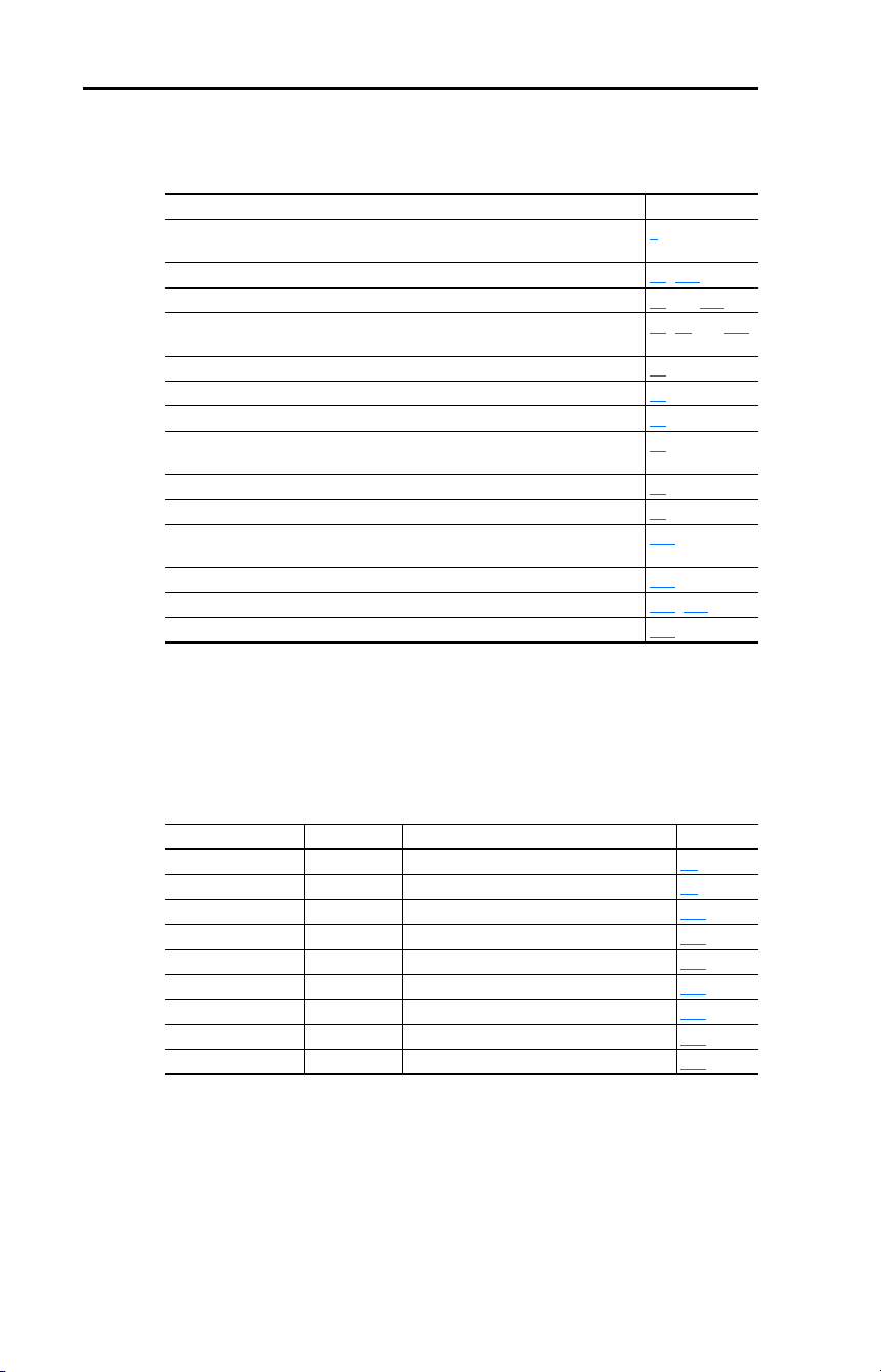
1. Press and hold in the tabs on each side of the cover.
2. Pull the cover out and up to release.
!
ATTENTION: The following information is merely a guide for proper
installation. Rockwell Automation, Inc. cannot assume responsibility
for the compliance or the noncompliance to any code, national, local or
otherwise for the proper installation of this drive or associated
equipment. A hazard of personal injury and/or equipment damage
exists if codes are ignored during installation.
Opening the Cover
12 Rockwell Automation Publication 22D-UM001F-EN-E - September 2024
Chapter 1 Installation/Wiring
• Mount the drive upright on a flat, vertical and level surface.
• Protect the cooling fan by avoiding dust or metallic particles.
• Do not expose to a corrosive atmosphere.
• Protect from moisture and direct sunlight.
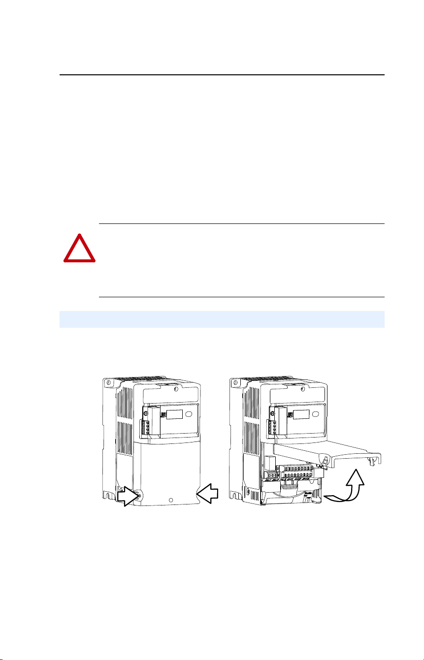
Minimum Mounting Clearances
See Appendix B for mounting dimensions.
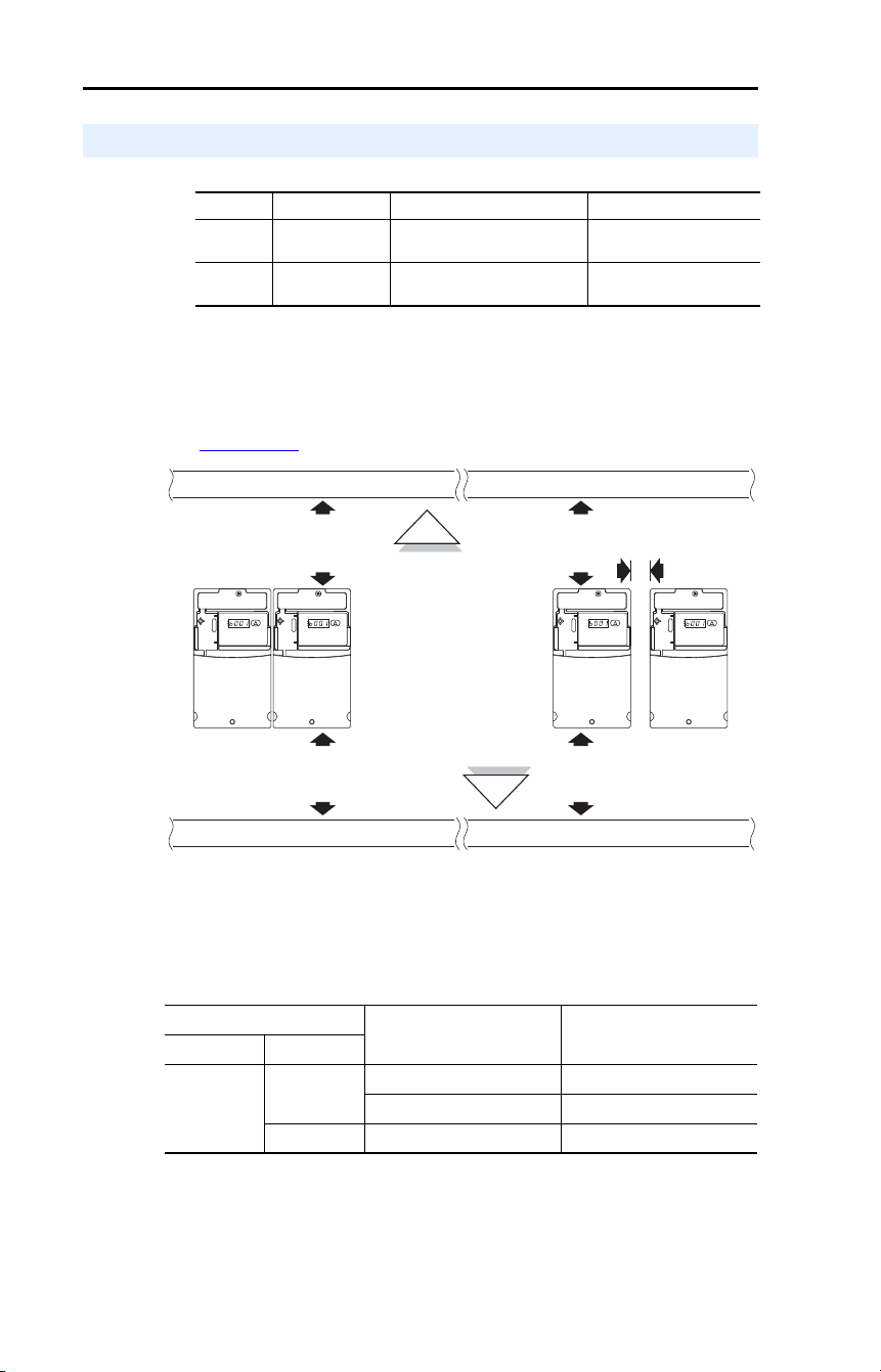
Ambient Operating Temperatures
Table 2 – Enclosure and Clearance Requirements
Mounting Considerations
Frame Screw Size Screw Torque DIN Rail
B M4 (#8-32)
1.56…1.96 N•m (14…17
lb•in)
35 mm (1.37 in.)
C M5 (#10-24)
2.45…2.94 N•m (22…26
lb•in)
–
Ambient Temperature Enclosure Rating Minimum Mounting
Clearances
Minimum Maximum
-10 °C (14 °F)
40 °C (104 °F)
IP20/Open Type Use Mounting Option A
IP30/NEMA 1/UL Type 1
(1)
(1)
Rating requires installation of the PowerFlex 40P IP30/NEMA 1/UL Type 1 option kit.
Use Mounting Option B
50 °C (122 °F) IP20/Open Type Use Mounting Option B
25 mm
(1.0 in.)
120 mm
(4.7 in.)
120 mm
(4.7 in.)
120 mm
(4.7 in.)
120 mm
(4.7 in.)
RUN
REV
FAULT
RUN
REV
FAULT
RUN
REV
FAULT
RUN
REV
FAULT
Mounting Option A
No clearance is required
between drives.
Mounting Option B
Closest object that
may restrict air flow
through the drive heat
sink and chassis

Rockwell Automation Publication 22D-UM001F-EN-E - September 2024 13
Chapter 1 Installation/Wiring
Debris Protection
A plastic top panel is included with the drive. Install the panel to prevent
debris from falling through the vents of the drive housing during
installation. Remove the panel for IP20/Open Type applications.
Storage
• Store within an ambient temperature range of -40…+85 °C
(-40…+185 °F).
• Store within a relative humidity range of 0…95%, non-condensing.
• Do not expose to a corrosive atmosphere.
For Plate drive installation instructions, see Appendix
H.
Plate Drive Installation
14 Rockwell Automation Publication 22D-UM001F-EN-E - September 2024
Chapter 1 Installation/Wiring
Ungrounded Distribution Systems
Disconnecting MOVs
To prevent drive damage, the MOVs connected to ground shall be
disconnected if the drive is installed on an ungrounded distribution
system where the line-to-ground voltages on any phase could exceed
125% of the nominal line-to-line voltage. To disconnect these devices,
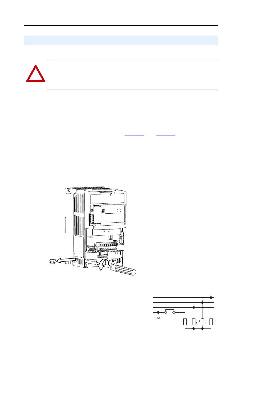
remove the jumper shown in the Figure 1
and Figure 2.
1. Turn the screw counterclockwise to loosen.
2. Pull the jumper completely out of the drive chassis.
3. Tighten the screw to keep it in place.
Figure 1 – Jumper Location (Typical)
Figure 2 – Phase to Ground MOV Removal
AC Supply Source Considerations
!
ATTENTION: PowerFlex 40P drives contain protective MOVs that
are referenced to ground. These devices must be disconnected if the
drive is installed on an ungrounded or resistive grounded distribution
system.
Important:
Tighten screw after
jumper removal.
R/L1
S/L2
T/L3
123
4
Three-Phase
AC Input
Jumper

Rockwell Automation Publication 22D-UM001F-EN-E - September 2024 15
Chapter 1 Installation/Wiring
Input Power Conditioning
The drive is suitable for direct connection to input power within the rated
voltage of the drive (see Appendix
A). Listed in Table 3 are certain input
power conditions which may cause component damage or reduction in
product life. If any of the conditions exist, as described in Table 3, install
one of the devices listed under the heading Corrective Action on the line
side of the drive.
Important: Only one device per branch circuit is required. It should be
mounted closest to the branch and sized to handle the total
current of the branch circuit.
Table 3 – Input Power Conditions
Input Power Condition Corrective Action
Low Line Impedance (less than 1% line reactance) • Install Line Reactor
(2)
, Isolation
Transformer, or Bus Inductor –
5.5 kW and 11 kW (7.5 HP and
15 HP) drives only
(2)
See for Appendix B for accessory ordering information.
Greater than 120 kVA supply transformer
Line has power factor correction capacitors • Install Line Reactor
• or Isolation Transformer
Line has frequent power interruptions
Line has intermittent noise spikes in excess of
6000V (lightning)
Phase to ground voltage exceeds 125% of normal
line to line voltage
• Remove MOV jumper to ground.
• or Install Isolation Transformer
with grounded secondary if
necessary.
Ungrounded distribution system
240V open delta configuration (stinger leg)
(1)
(1)
For drives applied on an open delta with a middle phase grounded neutral system, the
phase opposite the phase that is tapped in the middle to the neutral or earth is
referred to as the “stinger leg,” “high leg,” “red leg,” and so on. This leg should be
identified throughout the system with red or orange tape on the wire at each
connection point. The stinger leg should be connected to the center Phase B on the
reactor. See Table 22
for specific line reactor part numbers.
• Install Line Reactor
16 Rockwell Automation Publication 22D-UM001F-EN-E - September 2024
Chapter 1 Installation/Wiring
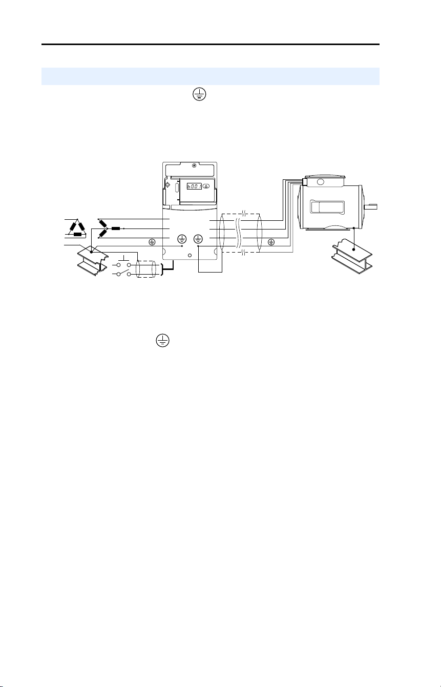
The drive Safety Ground - (PE) must be connected to system
ground. Ground impedance must conform to the requirements of
national and local industrial safety regulations and/or electrical codes.
The integrity of all ground connections should be periodically checked.
Figure 3 – Typical Grounding
Ground Fault Monitoring
If a system ground fault monitor (RCD) is to be used, only Type B
(adjustable) devices should be used to avoid nuisance tripping.
Safety Ground - (PE)
This is the safety ground for the drive that is required by code. One of
these points must be connected to adjacent building steel (girder, joist), a
floor ground rod or bus bar. Grounding points must comply with national
and local industrial safety regulations and/or electrical codes.
Motor Ground
The motor ground must be connected to one of the ground terminals on
the drive.
Shield Termination - SHLD
Either of the safety ground terminals located on the power terminal
block provides a grounding point for the motor cable shield. The motor
cable shield connected to one of these terminals (drive end) should also
be connected to the motor frame (motor end). Use a shield terminating or
EMI clamp to connect the shield to the safety ground terminal. The
conduit box option may be used with a cable clamp for a grounding point
for the cable shield.
When shielded cable is used for control and signal wiring, the shield
should be grounded at the source end only, not at the drive end.
General Grounding Requirements
SHLD
U/T1
V/T2
W/T3
R/L1
S/L2
T/L3
RUN
REV
FAULT

Rockwell Automation Publication 22D-UM001F-EN-E - September 2024 17
Chapter 1 Installation/Wiring
RFI Filter Grounding
Using an external filter with any drive rating, may result in relatively
high ground leakage currents. Therefore, the filter must only be used in
installations with grounded AC supply systems and be permanently
installed and solidly grounded (bonded) to the building power
distribution ground. Ensure that the incoming supply neutral is solidly
connected (bonded) to the same building power distribution ground.
Grounding must not rely on flexible cables and should not include any
form of plug or socket that would permit inadvertent disconnection.
Some local codes may require redundant ground connections. The
integrity of all connections should be periodically checked.
The PowerFlex 40P does not provide branch short circuit protection.
This product should be installed with either input fuses or an input
circuit breaker. National and local industrial safety regulations and/or
electrical codes may determine additional requirements for these
installations.
Fusing
The ratings in the table that follows are the recommended values for use
with each drive rating. The devices listed in this table are provided to
serve as a guide.
Bulletin 140M/140MT (Self-protected Combination Controller)/
UL489 Circuit Breakers
When using Bulletin 140M/140MT or UL489 rated circuit breakers, the
guidelines listed below must be followed in order to meet the NEC
requirements for branch circuit protection.
• Bulletin 140M/140MT can be used in single and group motor
applications.
• Bulletin 140M/140MT can be used up stream from the drive without
the need for fuses.
Fuses and Circuit Breakers

18 Rockwell Automation Publication 22D-UM001F-EN-E - September 2024
Chapter 1 Installation/Wiring
Table 4 – Recommended Branch Circuit Protective Device
Voltage
Rating
Drive Rating
kW (HP)
Fuse Rating
(1)
Amps
140M/140MT
Motor
Protectors
(2)
(3)
Catalog No.
Recommended
MCS Contactors
Catalog No.
Min. Enclosure
Volume
(4)
Inches
3
240V AC –
3-phase
0.4 (0.5) 6 140M-C2E-B40
140MT-C3E-B40
100-C09
100-E09
1655
0.75 (1.0) 10 140M-C2E-C10
140MT-C3E-C10
100-C09
100-E09
1655
1.5 (2.0) 15 140M-C2E-C16
140MT-C3E-C16
100-C12
100-E12
1655
2.2 (3.0) 25 140M-C2E-C16
140MT-C3E-C16
100-C23
100-E26
1655
3.7 (5.0) 30 140M-F8E-C25 100-C23
100-E26
1655
5.5 (7.5) 40 140M-F8E-C32 100-C37
100-E38
2069
7.5 (10.0) 60 140M-F8E-C45 100-C60
100-E65
2069
480V AC –
3-phase
0.4 (0.5) 3 140M-C2E-B25
140MT-C3E-B25
100-C09
100-E09
1655
0.75 (1.0) 6 140M-C2E-B40
140MT-C3E-B40
100-C09
100-E09
1655
1.5 (2.0) 10 140M-C2E-B63
140MT-C3E-B63
100-C09
100-E09
1655
2.2 (3.0) 15 140M-C2E-C10
140MT-C3E-C10
100-C09
100-E09
1655
4.0 (5.0) 20 140M-C2E-C16
140MT-C3E-C16
100-C23
100-E26
1655
5.5 (7.5) 25 140M-D8E-C20
140MT-D9E-C20
100-C23
100-E26
2069
7.5 (10.0) 30 140M-D8E-C20
140MT-D9E-C20
100-C23
100-E26
2069
11 (15) 50 140M-F8E-C32 100-C43
100-E40
2069

Rockwell Automation Publication 22D-UM001F-EN-E - September 2024 19
Chapter 1 Installation/Wiring
600V AC –
3-phase
0.75 (1.0) 6 140M-C2E-B25
140MT-C3E-B25
100-C09
100-E09
1655
1.5 (2.0) 6 140M-C2E-B40
140MT-C3E-B40
100-C09
100-E09
1655
2.2 (3.0) 10 140M-D8E-B63
140MT-D9E-B63
100-C09
100-E09
1655
4.0 (5.0) 15 140M-D8E-C10
140MT-D9E-C10
100-C09
100-E09
1655
5.5 (7.5) 20 140M-D8E-C16
140MT-D9E-C16
100-C16
100-E16
2066
7.5 (10.0) 25 140M-D8E-C16
140MT-D9E-C16
100-C23
100-E26
2066
11 (15.0) 40 140M-F8E-C25 100-C30
100-E30
2066
(1)
Recommended Fuse Type: UL Class J, CC, T or Type BS88; 600V (550V) or equivalent.
(2)
The AIC ratings of the Bulletin 140M/140MT devices can vary. See Motor Protection Circuit
Breaker and Motor Circuit Protector Specifications Technical Data, publication 140-TD005
or
140M-TD002
.
(3)
Manual Self-protected (Type E) Combination Motor Controller, UL listed for 208 Wye or Delta, 240
Wye or Delta, 480Y/277 or 600Y/347. Not UL Listed for use on 480V or 600V Delta/Delta, corner
ground, or high-resistance ground systems.
(4)
When using a Manual Self-protected (Type E) Combination Motor Controller, the drive must be
installed in a ventilated or non-ventilated enclosure with the minimum volume specified in this
column. Application specific thermal considerations may require a larger enclosure.
Table 4 – Recommended Branch Circuit Protective Device (Continued)
Voltage
Rating
Drive Rating
kW (HP)
Fuse Rating
(1)
Amps
140M/140MT
Motor
Protectors
(2)
(3)
Catalog No.
Recommended
MCS Contactors
Catalog No.
Min. Enclosure
Volume
(4)
Inches
3

20 Rockwell Automation Publication 22D-UM001F-EN-E - September 2024
Chapter 1 Installation/Wiring
Motor Cable Types Acceptable for 200…600V Installations
A variety of cable types are acceptable for drive installations. For many
installations, unshielded cable is adequate, provided it can be separated
from sensitive circuits. As an approximate guide, allow a spacing of
0.3 m (1 ft) for every 10 m (32.8 ft) of length. In all cases, long parallel
runs must be avoided. Do not use cable with an insulation thickness less
than 15 mils (0.4 mm [0.015 in.]). Do not route more than three sets of
motor leads in a single conduit to minimize “cross talk”. If more than
three drive/motor connections per conduit are required, shielded cable
must be used.
UL installations in 50 °C (122 °F) ambient must use 600V, 75 °C
(167 °F) or 90 °C (194 °F) wire.
UL installations in 40 °C (104 °F) ambient should use 600V, 75 °C
(167 °F) or 90 °C (194 °F) wire.
Use copper wire only. Wire gauge requirements and recommendations
are based on 75 °C (167 °F). Do not reduce wire gauge when using
higher temperature wire.
Unshielded
THHN, THWN or similar wire is acceptable for drive installation in dry
environments provided adequate free air space and/or conduit fill rates
limits are provided. Do not use THHN or similarly coated wire in wet
areas. Any wire chosen must have a minimum insulation thickness of 15
mils and should not have large variations in insulation concentricity.
Power Wiring
!
ATTENTION: National Codes and standards (NEC, VDE, BSI, and
so on.) and local codes outline provisions for safely installing electrical
equipment. Installation must comply with specifications regarding wire
types, conductor sizes, branch circuit protection and disconnect
devices. Failure to do so may result in personal injury and/or equipment
damage.
!
ATTENTION: To avoid a possible shock hazard caused by induced
voltages, unused wires in the conduit must be grounded at both ends.
For the same reason, if a drive sharing a conduit is being serviced or
installed, all drives using this conduit should be disabled. This will help
minimize the possible shock hazard from “cross coupled” power leads.

Rockwell Automation Publication 22D-UM001F-EN-E - September 2024 21
Chapter 1 Installation/Wiring
Shielded/Armored Cable
Shielded cable contains all of the general benefits of multi-conductor
cable with the added benefit of a copper braided shield that can contain
much of the noise generated by a typical AC Drive. Strong consideration
for shielded cable should be given in installations with sensitive
equipment such as weigh scales, capacitive proximity switches and other
devices that may be affected by electrical noise in the distribution
system. Applications with large numbers of drives in a similar location,
imposed EMC regulations or a high degree of communications /
networking are also good candidates for shielded cable.
Shielded cable may also help reduce shaft voltage and induced bearing
currents for some applications. In addition, the increased impedance of
shielded cable may help extend the distance that the motor can be
located from the drive without the addition of motor protective devices
such as terminator networks. See Reflected Wave chapter in Wiring and
Grounding for Pulse Width Modulated (PWM) AC Drives Installation
Instructions, publication DRIVES-IN001
.
Consideration should be given to all of the general specifications
dictated by the environment of the installation, including temperature,
flexibility, moisture characteristics and chemical resistance. In addition,
a braided shield should be included and be specified by the cable
manufacturer as having coverage of at least 75%. An additional foil
shield can greatly improve noise containment.
A good example of recommended cable is Belden 295xx (xx determines
gauge). This cable has four (4) XLPE insulated conductors with a 100%
coverage foil and an 85% coverage copper braided shield (with drain
wire) surrounded by a PVC jacket.
Other types of shielded cable are available, but the selection of these
types may limit the allowable cable length. Particularly, some of the
newer cables twist 4 conductors of THHN wire and wrap them tightly
with a foil shield. This construction can greatly increase the cable
charging current required and reduce the overall drive performance.
Unless specified in the individual distance tables as tested with the drive,
these cables are not recommended and their performance against the lead
length limits supplied is not known.

22 Rockwell Automation Publication 22D-UM001F-EN-E - September 2024
Chapter 1 Installation/Wiring
Recommended Shielded Wire
Reflected Wave Protection
The drive should be installed as close to the motor as possible.
Installations with long motor cables may require the addition of external
devices to limit voltage reflections at the motor (reflected wave
phenomena). See Table 5
for recommendations.
The reflected wave data applies to all frequencies 2…16 kHz.
For 240V ratings, reflected wave effects do not need to be considered.
Table 5 – Maximum Cable Length Recommendations
Output Disconnect
The drive is intended to be commanded by control input signals that will
start and stop the motor. A device that routinely disconnects then
reapplies output power to the motor for the purpose of starting and
stopping the motor should not be used. If it is necessary to disconnect
power to the motor with the drive outputting power, an auxiliary contact
should be used to simultaneously disable drive control run commands.
Location Rating/Type Description
Standard
(Option 1)
600V, 90 °C (194 °F)
XHHW2/RHW-2
Anixter
B209500…B209507,
Belden 29501…29507,
or equivalent
• Four tinned copper conductors with XLPE
insulation.
• Copper braid/aluminum foil combination shield
and tinned copper drain wire.
• PVC jacket.
Standard
(Option 2)
Tray rated 600V, 90 °C
(194 °F) RHH/RHW-2
Anixter OLF-7xxxxx or
equivalent
• Three tinned copper conductors with XLPE
insulation.
• 5 mil single helical copper tape (25% overlap
min.) with three bare copper grounds in contact
with shield.
• PVC jacket.
Class I and
II; Division I
and II
Tray rated 600V, 90 °C
(194 °F) RHH/RHW-2
Anixter 7V-7xxxx-3G or
equivalent
• Three bare copper conductors with XLPE
insulation and impervious corrugated
continuously welded aluminum armor.
• Black sunlight resistant PVC jacket overall.
• Three copper grounds on 6 mm
2
(10 AWG) and
smaller.
Reflected Wave
380-480V Ratings Motor Insulation Rating Motor Cable Only
(1)
(1)
Longer cable lengths can be achieved by installing devices on the output of the drive.
Consult factory for recommendations.
1000 Vp-p 15 m (49 ft)
1200 Vp-p 40 m (131 ft)
1600 Vp-p 170 m (558 ft)
Rockwell Automation Publication 22D-UM001F-EN-E - September 2024 23
Chapter 1 Installation/Wiring
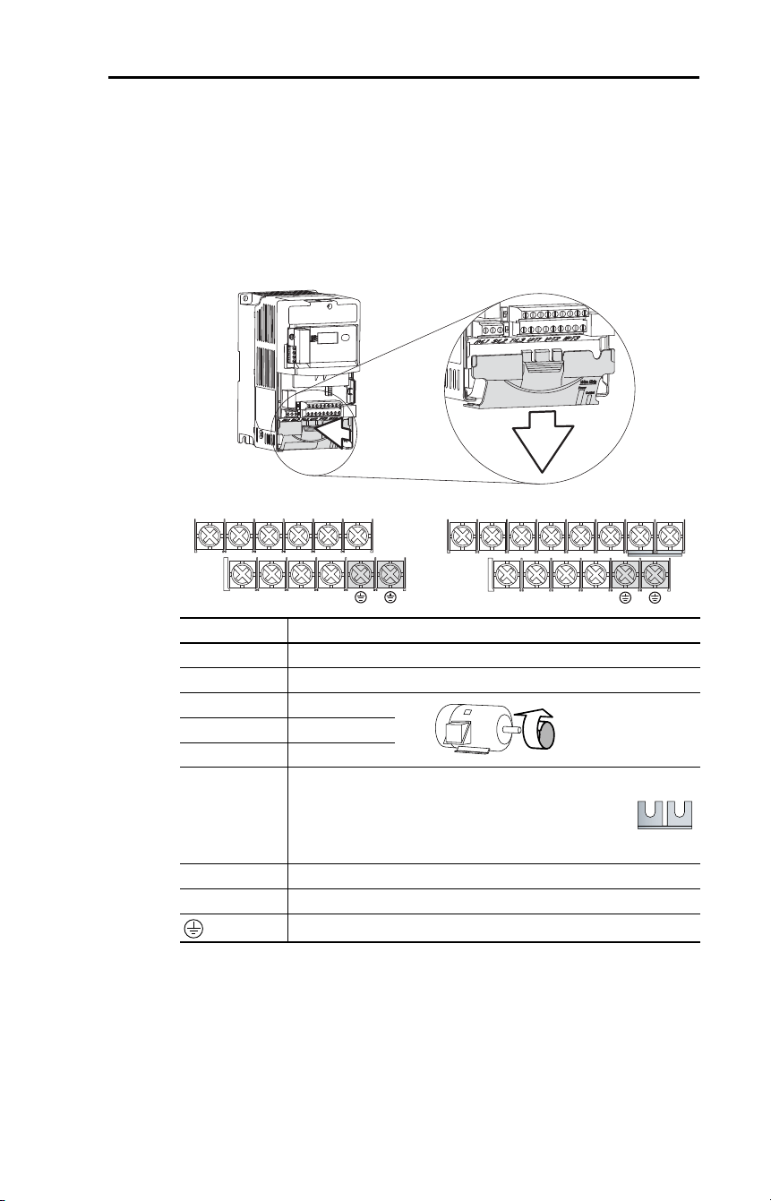
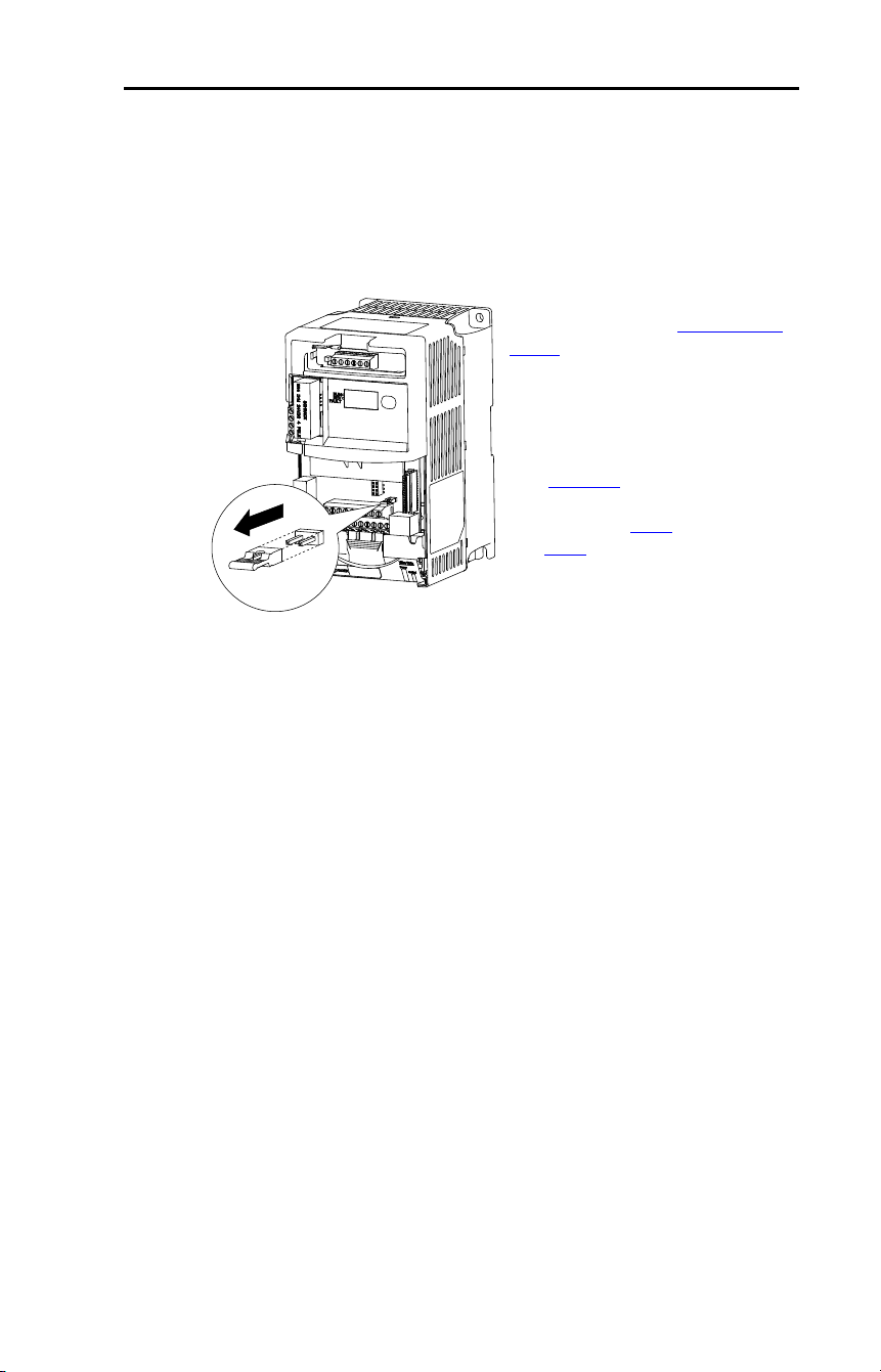
Power Terminal Block
The power terminal block is covered by a finger guard. To remove:
1. Press in and hold the locking tab.
2. Slide finger guard down and out.
Replace the finger guard when wiring is complete.
Figure 4 – Power Terminal Block (Typical)
Terminal
(1)
(1)
Important: Terminal screws may become loose during shipment. Ensure that all
terminal screws are tightened to the recommended torque before applying power to
the drive.
Description
R/L1, S/L2 1-Phase Input
(2)
(2)
Single-phase operation requires a 65% derate of drive rated current.
R/L1, S/L2, T/L3 3-phase Input
U/T1 To Motor U/T1
=
Switch any two motor
leads to change
forward direction.
V/T2 To Motor V/T2
W/T3 To Motor W/T3
P2, P1
DC Bus Inductor Connection (C Frame drives only.)
The C Frame drive is shipped with a jumper between
Terminals P2 and P1. Remove this jumper only when a DC
Bus Inductor will be connected. Drive will not power up
without a jumper or inductor connected.
DC+, DC- DC Bus Connection
BR+, BR- Dynamic Brake Resistor Connection
Safety Ground - PE
V/T2T/L3S/L2R/L1 U/T1 W/T3
BR+ BR-DC- DC+
V/T2T/L3S/L2R/L1 U/T1 W/T3 P2 P1
BR+ BR-DC- DC+
B Frame
C Frame
24 Rockwell Automation Publication 22D-UM001F-EN-E - September 2024
Chapter 1 Installation/Wiring
Table 6 – Power Terminal Block Specifications
If drives with internal precharge are used with a disconnect switch to the
common bus, then an auxiliary contact on the disconnect must be
connected to a digital input of the drive. The corresponding input
(parameter A051
…A054) must be set to option 29, “Precharge Enable.”
This provides the proper precharge interlock, guarding against possible
damage to the drive when connected to a common DC bus.
Motor Start/Stop Precautions
Important points to remember about I/O wiring:
• Always use copper wire.
• Wire with an insulation rating of 600V or greater is recommended.
• Control and signal wires should be separated from power wires by at
least 0.3 m (1 ft).
Important: I/O terminals labeled “Common” are not referenced to the
safety ground (PE) terminal and are designed to greatly
reduce common mode interference.
Frame Maximum Wire Size
(1)
(1)
Maximum/minimum sizes that the terminal block will accept - These are not
recommendations.
Minimum Wire Size
(1)
Torque
B 5.3 mm
2
(10 AWG) 1.3 mm
2
(16 AWG) 1.7…2.2 N•m (16…19 lb•in)
C 8.4 mm
2
(8 AWG) 1.3 mm
2
(16 AWG) 2.9…3.7 N•m (26…33 lb•in)
Common Bus/Precharge Notes
I/O Wiring Recommendations
!
ATTENTION: A contactor or other device that routinely disconnects
and reapplies the AC line to the drive to start and stop the motor can
cause drive hardware damage. The drive is designed to use control input
signals that will start and stop the motor. If used, the input device must
not exceed one operation per minute or drive damage can occur.
!
ATTENTION: The drive start/stop control circuitry includes
solid-state components. If hazards due to accidental contact with
moving machinery or unintentional flow of liquid, gas or solids exist,
an additional hardwired stop circuit may be required to remove the AC
line to the drive. When the AC line is removed, there will be a loss of
any inherent regenerative braking effect that might be present - The
motor will coast to a stop. An auxiliary braking method may be
required.

Rockwell Automation Publication 22D-UM001F-EN-E - September 2024 25
Chapter 1 Installation/Wiring
Signal and Control Wire Types
Table 7 – Recommended Signal Wire
Table 8 – Recommended Control Wire for Digital I/O
I/O Terminal Block
Table 9 – I/O Terminal Block Specifications
Maximum Control Wire Recommendations
Do not exceed control wiring length of 30 m (100 ft). Control signal
cable length is highly dependent on electrical environment and
installation practices. To improve noise immunity, the I/O terminal block
Common may be connected to ground terminal/protective earth. If using
the RS-485 (DSI) port, I/O Terminal 19 should also be connected to
ground terminal/protective earth.
!
ATTENTION: Driving the 4…20 mA analog input from a voltage
source could cause component damage. Verify proper configuration
prior to applying input signals.
Signal Type/
Where Used
Belden Wire Types
(1)
(or equivalent)
(1)
Stranded or solid wire.
Description
Min. Insulation
Rating
Analog I/O and
PTC
8760/9460 0.750 mm
2
(18 AWG), twisted
pair, 100% shield with drain
(3)
(3)
If the wires are short and contained within a cabinet which has no sensitive circuits,
the use of shielded wire may not be necessary, but is always recommended.
300V, 75…90 °C
(167…194 °F)
Remote Pot 8770 0.750 mm
2
(18 AWG),
3 conductor, shielded
Encoder/Pulse I/O 89730
(2)
(2)
9728 or 9730 are equivalent and may be used but may not fit in the drive wire channel.
0.196 mm
2
(24 AWG),
individually shielded pairs
Type Wire Type(s) Description
Minimum Insulation
Rating
Unshielded Per US NEC or applicable
national or local code
– 300V,
60 °C (140 °F)
Shielded Multi-conductor shielded
cable such as Belden
8770(or equivalent)
0.750 mm
2
(18 AWG),
3 conductor, shielded.
Frame Maximum Wire Size
(1)
(1)
Maximum/Minimum sizes that the terminal block will accept - These are not
recommendations.
Minimum Wire Size
(1)
Torque
B and C 1.3 mm
2
(16 AWG) 0.2 mm
2
(24 AWG) 0.5…0.8 N•m
(4.4…7 lb•in)
26 Rockwell Automation Publication 22D-UM001F-EN-E - September 2024
Chapter 1 Installation/Wiring
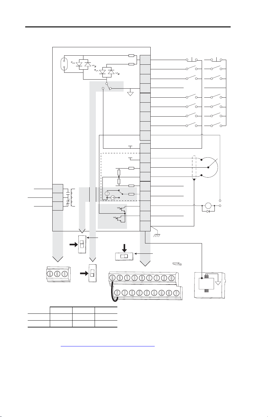
Figure 5 – Control Wiring Block Diagram
See Control Wiring Block Diagram Notes on the next page.
04
05
06
07
01
02
03
08
09
11
12
13
14
15
16
17
18
19
Digital Common
Digital Input 1
Digital Input 2
Digital Input 3
Stop
(1)(6)
Start/Run FWD
(2)
Direction/Run REV
(3)
Digital Input 4
Opto Common
R1
R2
R3
Relay N.O.
Relay Common
Relay N.C.
+24V DC
+10V DC
0-10V (or ±10V) Input
(4)
Analog Common
4-20 mA Input
Analog Output
Opto Output 1
Opto Output 2
RS485 Shield
+24V
+10V
Typical
SNK Wiring
Typical
SRC Wiring
1
RS-485
(DSI)
R1 R2 R3
SNK
SRC
0-10V
0-20mA
01 02 03 04 05
11 12 13 14 15
06 07 08 09
16 17 18 19
(1)
Enable Jumper
(6)
30V DC
50 mA
Non-inductive
Common
24V
ENBL
Enable
(6)
Jumper
(5)
Pot must be
1…10 kΩ
2 Watt Min
0-10V
0/4-20 mA
Analog Output Select
Voltage Range Select
SRCSNK
10V
10V
±
(4)
30V DC 125V AC 240V AC
Resistive 3.0 A 3.0 A 3.0 A
Inductive 0.5 A 0.5 A 0.5 A

Rockwell Automation Publication 22D-UM001F-EN-E - September 2024 27
Chapter 1 Installation/Wiring
Control Wiring Block Diagram Notes
(1)
Important: I/O Terminal 01 is always a coast-to-stop input except when P036 [Start
Source] is set to “3-Wire”, “2-W Lvl Sens” or “Momt FWD/REV” control. In three wire
control, I/O Terminal 01 is controlled by P037
[Stop Mode]. All other stop sources are
controlled by P037 [Stop Mode].
Important: The drive is shipped with a jumper installed between I/O Terminals 01 and
11. Remove this jumper when using I/O Terminal 01 as a stop or enable input.
(2)
Two wire control shown. For three wire control use a momentary input on I/O
Terminal 02 to command a start. Use a maintained input for I/O Terminal 03 to
change direction.
(3)
The function of I/O Terminal 03 is fully programmable. Program with E202 [Digital
Term 3].
(4)
Match the Voltage Range Select DIP Switch setting with the control scheme for proper
Uni-Polar or Bipolar analog input operation.
(5)
When using an opto output with an inductive load such as a relay, install a recovery
diode parallel to the relay as shown, to prevent damage to the output.
(6)
When the ENBL enable jumper is removed, I/O Terminal 01 will always act as a
hardware enable, causing a coast-to-stop without software interpretation.
P036 [Start Source] Stop I/O Terminal 01 Stop
3-wire Per P037 Per P037
(6)
2-wire Per P037 Coast
2-W Lvl Sens Per P037 Per P037
(6)
2-W Hi Speed Per P037 Coast
RS-485 Port Per P037 Coast
Momt FWD/REV Per P037 Per P037
(6)
28 Rockwell Automation Publication 22D-UM001F-EN-E - September 2024
Chapter 1 Installation/Wiring
Table 10 – Control I/O Terminal Designations
No. Signal Default Description Parameter
R1 Relay N.O. Fault Normally open contact for output relay. A055
R2 Relay Common – Common for output relay.
R3 Relay N.C. Fault Normally closed contact for output relay. A055
Analog Output Select DIP
Switch
0-10V Sets analog output to either voltage or current. Setting must match
A065 [Analog Out Sel].
Sink/Source DIP Switch Source (SRC) Inputs can be wired as Sink (SNK) or Source (SRC) via DIP Switch
setting.
01 Stop
(1)
Coast The factory installed jumper or a normally closed
input must be present for the drive to start.
P036
(1)
02 Start/Run FWD Not Active I/O Terminal 03 is fully programmable. Program with
E202 [Digital Term 3]. To disable reverse operation,
see A095 [Reverse Disable].
P036
, P037
03 Digital Term 3 Not Active P036, P037,
A095
, E202
04 Digital Common – For digital inputs. Electronically isolated with digital
inputs from analog I/O and opto outputs.
05 Digital Input 1 Preset Freq Program with A051 [Digital In1 Sel]. A051
06 Digital Input 2 Preset Freq Program with A052 [Digital In2 Sel]. A052
07 Digital Input 3 Local Program with A053 [Digital In3 Sel]. A053
08 Digital Input 4 Jog Forward Program with A054 [Digital In4 Sel]. A054
09 Opto Common – For opto-coupled outputs. Electronically isolated with
opto outputs from analog I/O and digital inputs.
11 +24V DC – Referenced to Digital Common.
Drive supplied power for digital inputs.
Maximum output current is 100 mA.
12 +10V DC – Referenced to Analog Common.
Drive supplied power for 0…10V external
potentiometer.
Maximum output current is 15 mA.
P038
13 ±10V In
(2)
Not Active For external 0…10V (unipolar) or ±10V (bipolar) input
supply (input impedance = 100 kΩ) or potentiometer
wiper.
P038
,
A051
…A054,
A123
, A132
14 Analog Common – For 0…10V In or 4…20 mA In. Electronically isolated
with analog inputs and outputs from digital I/O and
opto outputs.
15 4…20 mA In
(2)
Not Active For external 4…20 mA input supply
(input impedance = 250 Ω).
P038,
A051
…A054,
A132
16 Analog Output OutFreq 0-10 The default analog output is 0…10V. To covert to a
current value, change the Analog Output Select DIP
Switch to 0…20mA. Program with A065 [Analog Out
Sel]. Max analog value can be scaled with A066
[Analog Out High].
Maximum Load: 4…20 mA = 525 Ω (10.5V)
0…10V = 1 kΩ (10 mA)
A065
, A066
17 Opto Output 1 MotorRunning Program with A058 [Opto Out1 Sel] A058, A059,
A064
18 Opto Output 2 At Frequency Program with A061 [Opto Out2 Sel] A061, A062,
A064
19 RS-485 (DSI) Shield – Terminal should be connected to safety ground - PE
when using the RS-485 (DSI) communications port.
(1)
See Control Wiring Block Diagram Notes (1) and (6).
(2)
0…10V In and 4…20 mA In are distinct input channels and may be connected simultaneously.
Inputs may be used independently for speed control or jointly when operating in PID mode.
Rockwell Automation Publication 22D-UM001F-EN-E - September 2024 29
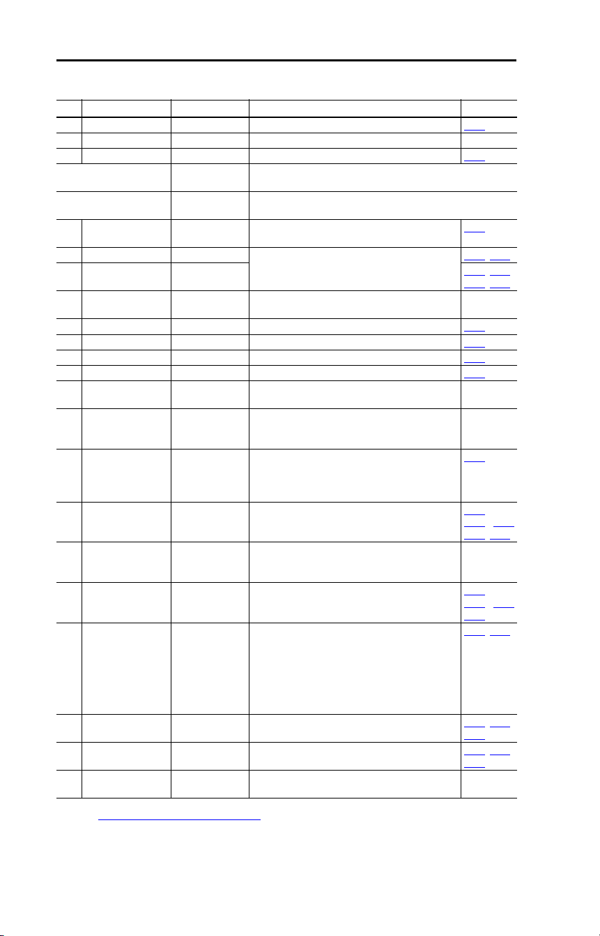
Chapter 1 Installation/Wiring
Encoder Interface
The PowerFlex 40P Encoder Interface can source 5V or 12V power and
accept 5V, 12V, or 24V single ended or differential inputs.
Table 11 – Terminal Description
Important: A quadrature encoder provides rotor speed and direction.
Therefore, the encoder must be wired such that the forward
direction matches the motor forward direction. If the drive
is reading encoder speed but the position regulator or other
encoder function is not working properly, remove power to
the drive and swap the A and A (NOT) encoder channels or
swap any two motor leads. Drives using FRN 2.xx and
greater will fault when an encoder is incorrectly wired and
E216
[Motor Fdbk Type] is set to option 5 “Quad Check”.
No. Signal Description
+V 5V-12V Power
(1)
(1)
When using 12V Encoder power, 24V I/O power, maximum output current at I/O
Terminal 11 is 50 mA.
Internal power source 250 mA (isolated).
Cm Power Return
B- Encoder B (NOT)
Quadrature B input.
B Encoder B
A- Encoder A (NOT)
Single channel, pulse train, or quadrature A input.
A Encoder A
➊ Output DIP switch selects 12 or 5 volt power supplied at terminals “+V”
and “Cm” for the encoder.
+V Cm B- B
A-
A
12V
5V
➊
30 Rockwell Automation Publication 22D-UM001F-EN-E - September 2024
Chapter 1 Installation/Wiring
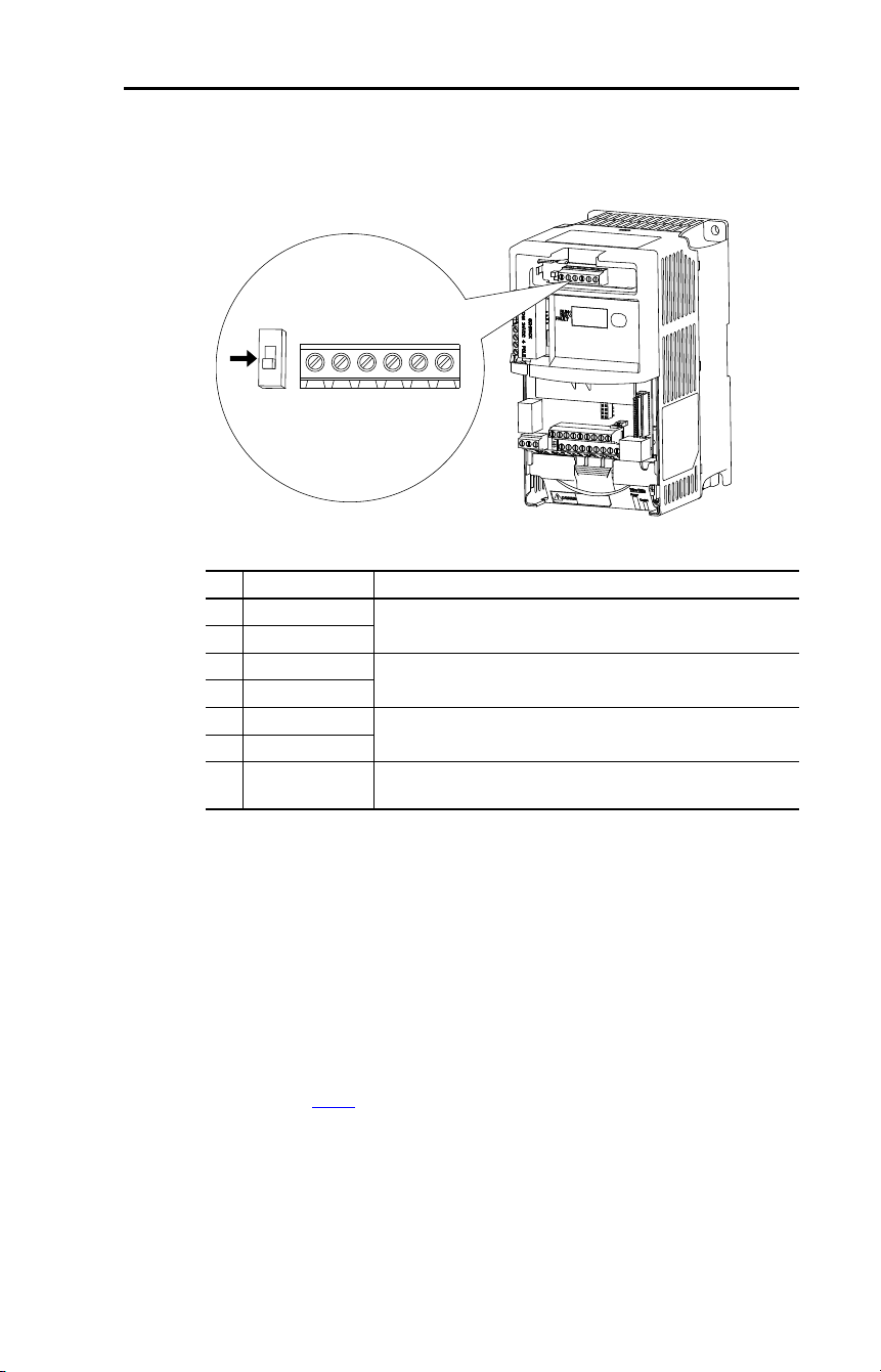
Figure 6 – Sample Encoder Wiring
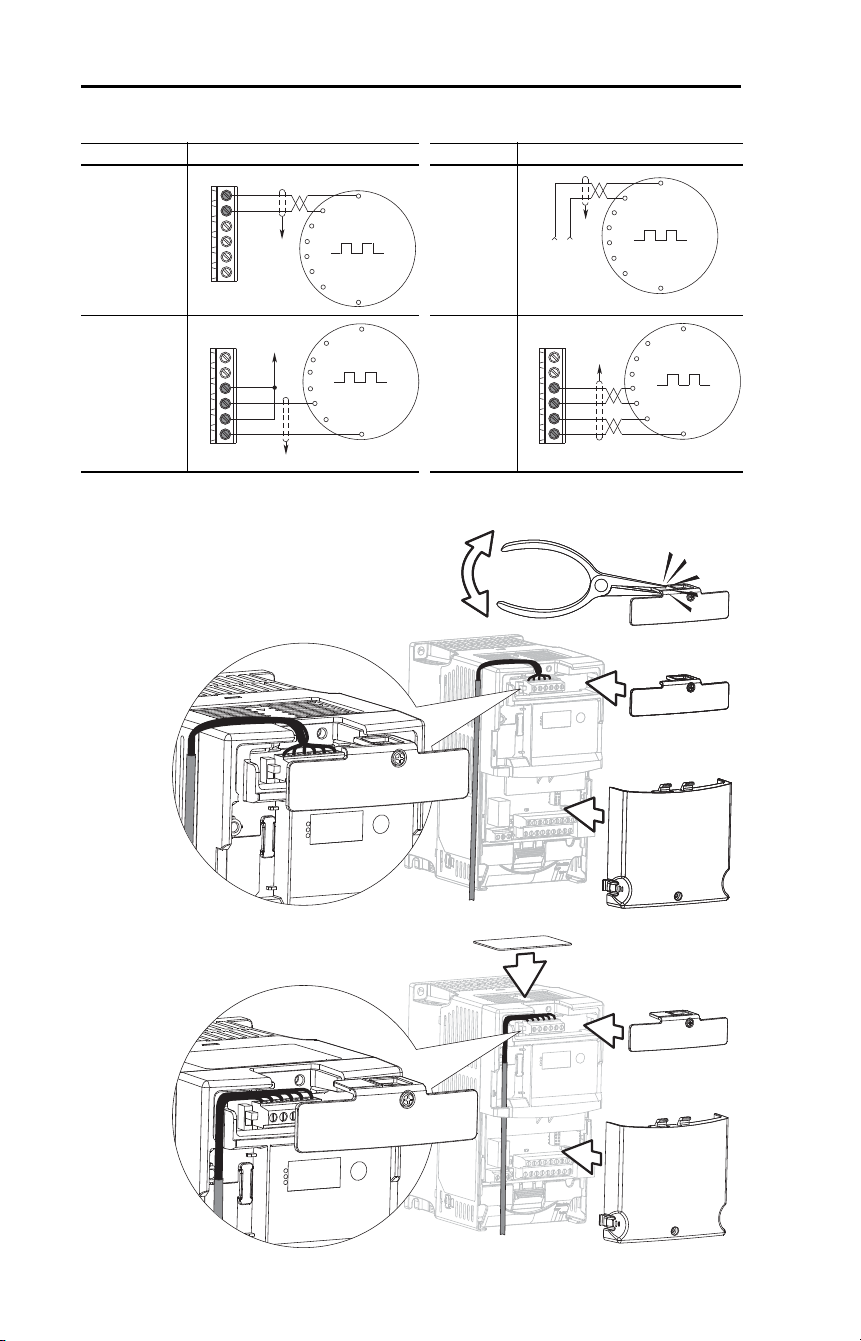
Figure 7 – Encoder Wire Routing Options
I/O Connection Example I/O Connection Example
Encoder
Power –
Internal Drive
Power
Internal (drive)
12V DC,
250 mA
Encoder
Power –
External
Power
Source
Encoder
Signal –
Single-Ended,
Dual Channel
Encoder
Signal –
Differential,
Dual
Channel
Common
+12V DC
(250 mA)
A
A-
B
B-
Cm
+V
to SHLD
+
Common
External
Power
Supply
to
SHLD
A NOT
A
B
B NOT
to SHLD
to Power Supply
Common
A
A-
B
B-
Cm
+V
to SHLD
A NOT
B
A
B NOT
A
A-
B
B-
Cm
+V
SK-U1-DCVR4-EN
IP20/Open Type
SK-U1-DCVR4-EN
IP30/NEMA 1/UL Type 1
Rockwell Automation Publication 22D-UM001F-EN-E - September 2024 31
Chapter 1 Installation/Wiring
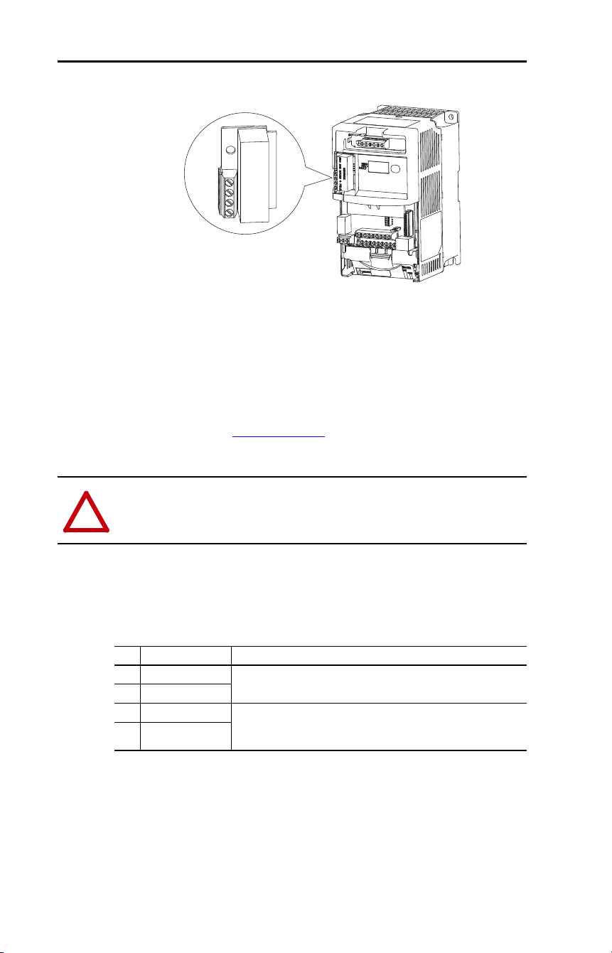
Hardware Enable Circuitry
I/O Terminal 01 is always a stop input. The status of this input is
interpreted by drive software. If the application requires the drive to be
disabled without software interpretation, a hardware enable
configuration can be utilized. This is done by removing the ENBL
enable jumper and wiring the enable input to I/O Terminal 1 (see below).
1. Remove drive cover as
described in section Opening the
Cover.
2. Locate and remove the Enable
Jumper on the Main Control Board
(see diagram).
3. Wire Enable to I/O Terminal 1
(see Table 10
). The drive will
always coast to a stop regardless of
the settings of P036 [Start Source]
and P037
[Stop Mode].
4. If I/O Terminal 01 is used as
hardware enable and 3-wire control
is needed, program one of the
digital inputs for the desired stop
mode.
32 Rockwell Automation Publication 22D-UM001F-EN-E - September 2024
Chapter 1 Installation/Wiring
User Installed DriveGuard Safe-Off Option (Series B)
The DriveGuard Safe-Off Option (Series B) board, when used with
suitable safety components, provides protection according to EN ISO
13849-1:2008+AC:2009; Performance Level d (Safety Category 3) for
safe off and protection against restart. The PowerFlex safe off option is
just one safety control system. All components in the system must be
chosen and applied correctly to achieve the desired level of operator
safeguarding. See DriveGuard Safe Torque Off Option (Series B) for
PowerFlex 40P and PowerFlex 70 Enhanced Control AC Drives User
Manual, publication PFLEX-UM003
for detailed installation
information.
Important: When using the DriveGuard Safe-Off Option (Series B)
with the drive in an IP30/NEMA 1/UL Type 1 installation,
only use low voltage Class 2 circuits.
Table 12 – Safe-Off Option Terminal Description
1
2
3
4
!
ATTENTION: Hazard of injury exists due to electric shock. Only
install a series B or greater DriveGuard Safe-Off Option in a PowerFlex
40P Drive.
No. Signal Description
4 24V Common
Connections for user supplied power to energize coil.
3 +24V DC
2 Common - N.C. Normally closed contacts for monitoring relay status.
Maximum Resistive Load: 250V AC / 30V DC / 50 VA / 60 Watts
Maximum Inductive Load: 250V AC / 30V DC / 25 VA / 30 Watts
1 Monitor - N.C.
Rockwell Automation Publication 22D-UM001F-EN-E - September 2024 33
Chapter 1 Installation/Wiring
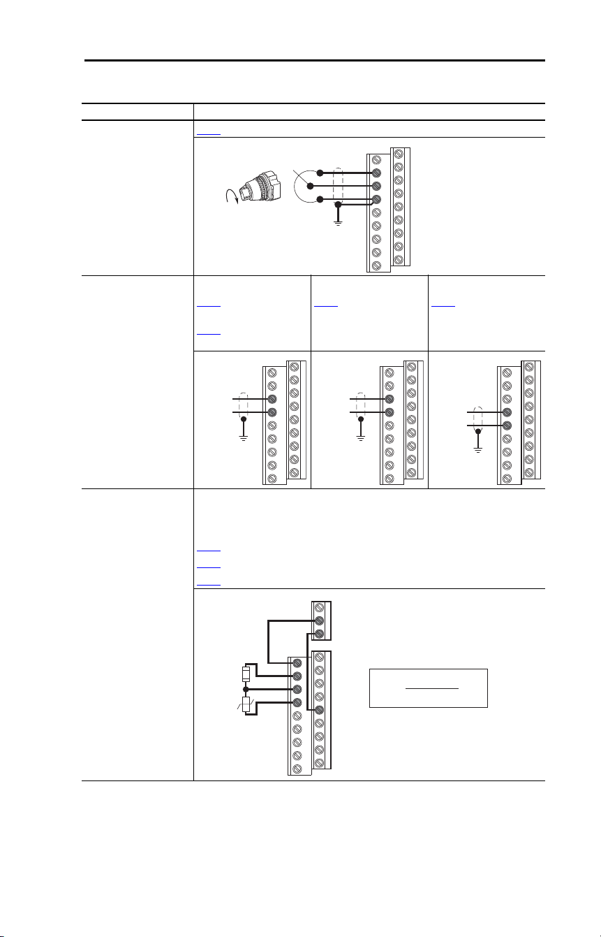
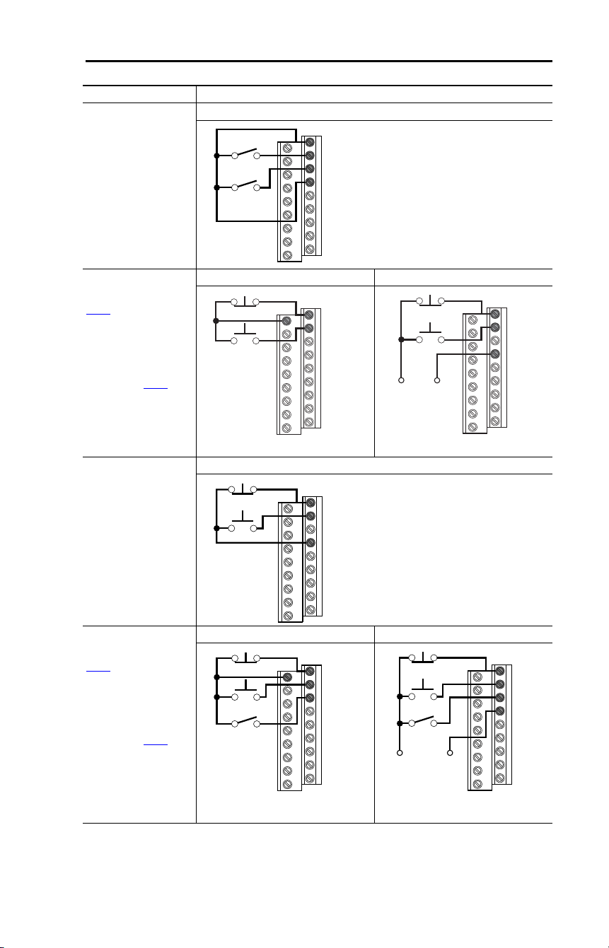
I/O Wiring Examples
Input/Output Connection Example
Potentiometer
1…10 kΩ Pot.
Recommended
(2 Watt minimum)
P038
[Speed Reference] = 2 “0-10V Input”
Analog Input
0…10V, 100k Ω
impedance
4…20 mA, 250 Ω
impedance
Bipolar
P038
[Speed Reference]
= 2 “0-10V Input” and
A123
[10V Bipolar Enbl]
= 1 “Bi-Polar In”
Unipolar (Voltage)
P038
[Speed Reference]
= 2 “0-10V Input”
Unipolar (Current)
P038 [Speed Reference]
= 3 “4-20 mA Input”
Analog Input, PTC
For Drive Fault
Wire the PTC and External Resistor (typically matched to the PTC Hot
Resistance) to I/O Terminals 12, 13, 14.
Wire R2/R3 Relay Output (SRC) to I/O Terminals 5 and 11.
A051
[Digital In1 Sel] = 3 “Aux Fault”
A055
[Relay Out Sel] = 10 “Above Anlg V”
A056
[Relay Out Level] = % Voltage Trip
12
13
14
13
14
-/+ 10V
Common
13
14
+
Common
14
15
Common
+
11
12
13
14
R2
R3
05
%V
Tr i p
=
×
100
R
PTC (hot)
R
PTC (hot)
+ R
e
R
e
R
PTC
34 Rockwell Automation Publication 22D-UM001F-EN-E - September 2024
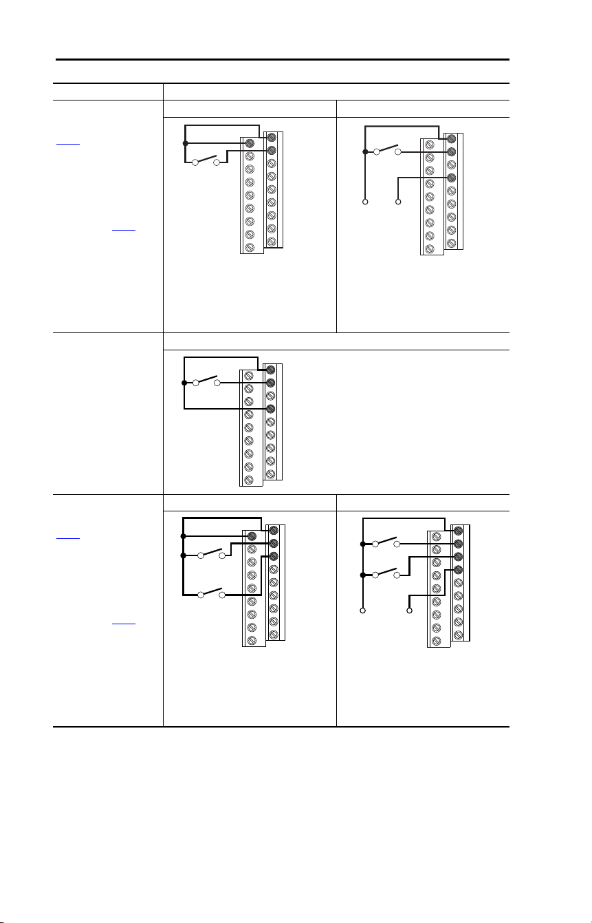
Chapter 1 Installation/Wiring
2-wire SRC Control -
Non-reversing
P036
[Start Source] =
2, 3, or 4
Input must be active for
the drive to run. When
input is opened, the
drive will stop as
specified by P037
[Stop Mode].
If desired, a User
Supplied 24V DC
power source can be
used. See the
“External Supply
(SRC)” example.
Internal Supply (SRC) External Supply (SRC)
2-wire SNK Control -
Non-reversing
Internal Supply (SNK)
2-wire SRC Control -
Run FWD/Run REV
P036
[Start Source] =
2, 3, or 4
Input must be active for
the drive to run. When
input is opened, the
drive will stop as
specified by P037
[Stop Mode].
If both Run Forward
and Run Reverse
inputs are closed at the
same time, an
undetermined state
could occur.
Internal Supply (SRC) External Supply (SRC)
Input/Output Connection Example
11
01
02
Stop-Run
+24V Common
01
02
04
Stop-Run
Each digital input draws 6 mA.
01
02
04
Stop-Run
11
01
02
03
Stop-Run
Forward
Stop-Run
Reverse
Common
01
02
03
04
Stop-Run
Forward
Stop-Run
Reverse
+24V
Each digital input draws 6 mA.
Rockwell Automation Publication 22D-UM001F-EN-E - September 2024 35
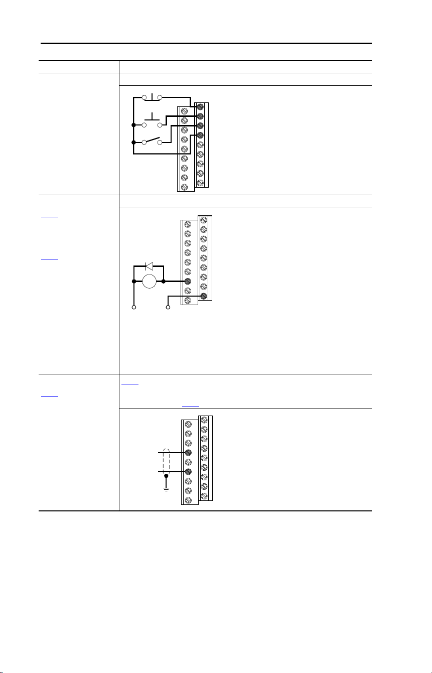
Chapter 1 Installation/Wiring
2-wire SNK Control -
Run FWD/Run REV
Internal Supply (SNK)
3-wire SRC Control -
Non-reversing
P036
[Start Source] = 1
A momentary input will
start the drive. A stop
input to I/O Terminal 01
will stop the drive as
specified by P037
[Stop Mode].
Internal Supply (SRC) External Supply (SRC)
3-wire SNK Control -
Non-reversing
Internal Supply (SNK)
3-wire SRC Control -
Reversing
P036
[Start Source] = 1
A momentary input will
start the drive. A stop
input to I/O Terminal 01
will stop the drive as
specified by P037
[Stop Mode]. I/O
Terminal 03
determines direction.
Internal Supply (SRC) External Supply (SRC)
Input/Output Connection Example
Stop-Run
Forward
Stop-Run
Reverse
01
02
03
04
11
01
02
Stop
Start
01
02
04
+24V
Common
Stop
Start
Each digital input draws 6 mA.
Stop
Start
01
02
03
04
11
01
02
03
Stop
Start
Direction
+24V Common
Stop
Start
Direction
01
02
03
04
Each digital input draws 6 mA.
36 Rockwell Automation Publication 22D-UM001F-EN-E - September 2024
Chapter 1 Installation/Wiring
3-wire SNK Control -
Reversing
Internal Supply (SNK)
Opto Output (1 and 2)
A058
[Opto Out1 Sel]
determines Opto
Output 1 (I/O Terminal
17) operation.
A061
[Opto Out2 Sel]
determines Opto
Output 2 (I/O Terminal
18) operation.
When using Opto
Output with an
inductive load such as
a relay, install a
recovery diode parallel
to the relay as shown,
to prevent damage to
the output.
Opto Output 1
Analog Output
A065
[Analog Out Sel]
determines analog
output type and drive
conditions.
0
…10V,
1 kΩ minimum
0…20 mA/4…20 mA,
525 Ω maximum
A065
[Analog Out Sel] = 0…14
The Analog Output Select DIP Switch must be set to match the analog output
signal mode set in A065
[Analog Out Sel].
Input/Output Connection Example
Stop
Start
Direction
01
02
03
04
Common+24V
CR
09
17
Each Opto Output is rated
30V DC 50 mA (Non-inductive).
14
16
Common
+
Rockwell Automation Publication 22D-UM001F-EN-E - September 2024 37
Chapter 1 Installation/Wiring
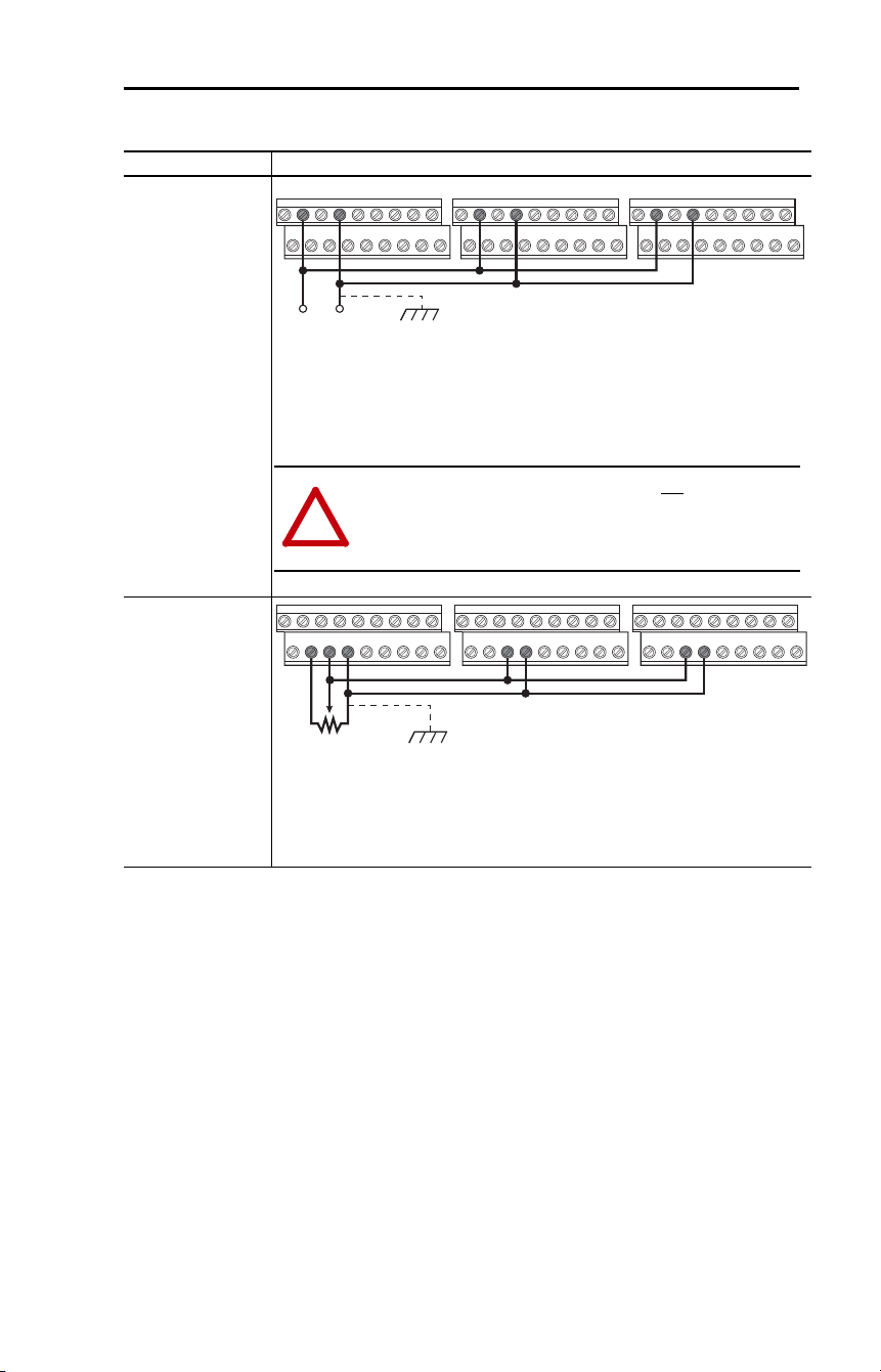
Typical Multiple Drive Connection Examples
Input/Output Connection Example
Multiple Digital
Input Connections
Customer Inputs can
be wired per
External Supply
(SRC).
When connecting a single input such as Run, Stop, Reverse or Preset Speeds to
multiple drives, it is important to connect I/O Terminal 04 common together for all
drives. If they are to be tied into another common (such as earth ground or
separate apparatus ground) only one point of the daisy chain of I/O Terminal 04
should be connected.
Multiple Analog
Connections
When connecting a single potentiometer to multiple drives it is important to
connect I/O Terminal 14 common together for all drives. I/O Terminal 14 common
and I/O Terminal 13 (potentiometer wiper) should be daisy-chained to each drive.
All drives must be powered up for the analog signal to be read correctly.
Customer Inputs Optional Ground Connection
04020402 0402
!
ATTENTION: I/O Common terminals should not be tied together
when using SNK (Internal Supply) mode. In SNK mode, if power is
removed from one drive, inadvertent operation of other drives that
share the same I/O Common connection may occur.
Remote Potentiometer Optional Ground Connection
12 13 1413 14 13 14
38 Rockwell Automation Publication 22D-UM001F-EN-E - September 2024
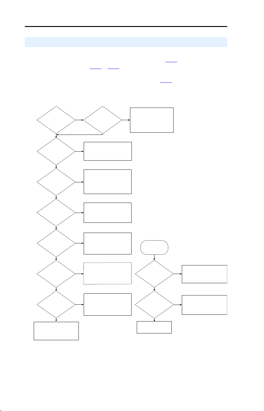
Chapter 1 Installation/Wiring
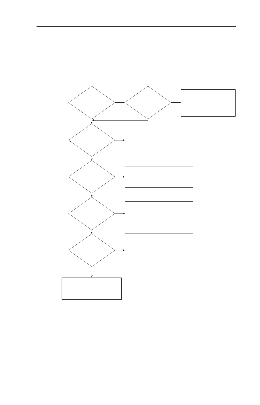
The drive speed command can be obtained from a number of different
sources. The source is normally determined by P038
[Speed Reference].
However, when A051
…A054 [Digital Inx Sel] is set to option 2, 4, 5, 6, 11,
12, 13, 14, 15 and the digital input is active, or if A132 is not set to
option 0, the speed reference commanded by P038 [Speed Reference] will
be overridden. See the chart below for the override priority.
Start and Speed Reference Control
Jog Input
Enabled and Active:
A051, A052, A053,
or A054 = 2, 11, 12
No
Ye s
Drive Stopped
(Not Running)
No
Ye s
Drive will Start and Run
at Jog Speed.
Direction comes from
I/O Terminal 03 Dir/Run REV
Jog Forward/Jog Reverse command
or
Comm Select Input
Enabled and Active:
[Digital Inx Sel] = 6
No
Start, Speed, and Direction commands
come from RS-485 (DSI) port.
Ye s
0…10V Override
Enabled and Active:
[Digital Inx Sel] = 13
No
Speed commands come from
0…10V or -10…+10V.
Start and Direction
follows P036 [Start Source]
or
Ye s
Bi-polar input when enabled.
Speed commands come from 4…20mA.
Start and Direction
follows P036 [Start Source].
4…20 mA Override
Enabled and Active:
[Digital Inx Sel] = 14
No
Ye s
P038 [Speed Reference]
= 4 or 5
No
Ye s
Run as specified by
P038 [Speed Reference].
Start and Direction commands come
from P036 [Start Source].
Run as specified by
A071…A077 [Preset Freq 1…7].
Start and Direction commands come
from P036 [Start Source].
A051/A052/A053
Preset Inputs Active
No
Ye s
Run as specified by
A132 [PID Ref Sel].
Start and Direction commands come
from P036 [Start Source].
PID Enabled:
A132 [PID Ref Sel]
≠
0
No
Ye s
Run as specified by
P038 [Speed Reference].
Start and Direction commands come
from P036 [Start Source].
All Results
No change in control.
Run according to Priority Checklist.
Encoder Enabled
P038 = 8
or
A132 = 9
No
Ye s
Speed Commands as defined.
Encoder provides trim.
No change in direction control.
Encoder Type Selected:
A216 [Motor Fdbk Type]
≠
0
No
Ye s
No change in control.
Rockwell Automation Publication 22D-UM001F-EN-E - September 2024 39
Chapter 1 Installation/Wiring
Accel/Decel Selection
The Accel/Decel rate can be obtained by a variety of methods. The
default rate is determined by P039 [Accel Time 1] and P040 [Decel Time
1]. Alternative Accel/Decel rates can be made through digital inputs,
RS-485 (DSI) communications and/or parameters. See the chart below
for the override priority.
No
Yes
No
RS-485 (DSI) Port
Controls Speed
No
Yes
Drive Stopped
(Not Running)
Yes
Either
P039 [Accel Time 1]/P040 [Decel Time 1]
or
A067 [Accel Time 2]/A068 [Decel Time 2]
can be selected when
RS-485 (DSI) port is active.
Input is programmed
as "Accel 2 & Decel 2"
A051, A052, A053,
or A054 = 1
No
Yes
P039 [Accel Time 1]/P040 [Decel Time 1]
or
A067 [Accel Time 2]/A068 [Decel Time 2]
is active when input is active.
Speed is controlled
by [Preset Freq x]
No
Yes
P039 [Accel Time 1]/P040 [Decel Time 1];
A067 [Accel Time 2]/A068 [Decel Time 2]
determined by the active
Preset Frequency.
See A070…A077 [Preset Freq 0…7]
Either
P039 [Accel Time 1]/P040 [Decel Time 1]
or
A067 [Accel Time 2]/A068 [Decel Time 2]
can be selected by:
Step Logic parameters A140…A147
or
Position Logic parameters E230…E245
Speed is controlled
by Stp Logic or
Pos Logic
No
Yes
P039 [Accel Time 1]/P040 [Decel Time 1]
are used.
Drive will Start and Run
at Jog Speed.
Drive will use A079 [Jog Accel/Decel]
Direction comes from
I/O Terminal 03 Dir/Run REV
Jog Input
Enabled and Active:
A051, A052, A053,
or A054 = 2, 11,12

40 Rockwell Automation Publication 22D-UM001F-EN-E - September 2024
Chapter 1 Installation/Wiring
CE Conformity
(1)
Conformity with the Low Voltage (LV) Directive and Electromagnetic
Compatibility (EMC) Directive has been demonstrated using
harmonized European Norm (EN) standards published in the Official
Journal of the European Communities. PowerFlex Drives comply with
the EN standards listed below when installed according to the User
Manual.
CE Declarations of Conformity are available online at:
rok.auto/certifications
Low Voltage Directive (2014/35/EU)
• EN61800-5-1 Adjustable speed electrical power drive systems – Part
5-1: Safety requirements – Electrical, thermal and energy.
EMC Directive (2014/30/EU)
• EN61800-3 Adjustable speed electrical power drive systems Part 3:
EMC product standard including specific test methods.
Machine Directive (2006/42/EC)
• EN62061 Safety of machinery – Functional safety of safety-related
electrical, electronic and programmable electronic control systems.
General Notes
• If the plastic top panel is removed, or the encoder cover is not intact,
or the optional conduit box is not installed, the drive must be
installed in an enclosure with side openings less than 12.5 mm
(0.5 in.) and top openings less than 1.0 mm (0.04 in.) to maintain
compliance with the LV Directive.
• The motor cable should be kept as short as possible in order to avoid
electromagnetic emission as well as capacitive currents.
• Use of line filters in ungrounded systems is not recommended.
• Conformity of the drive with CE EMC requirements does not
guarantee an entire machine installation complies with CE EMC
requirements. Many factors can influence total machine/installation
compliance.
• If the DriveGuard Safe-Off Option (Series B) is installed, use only
low voltage Class 2 circuits.
• When using the DriveGuard Safe-Off Option (Series B), the
installation must meet all the requirements listed in the DriveGuard
Safe Torque Off Option (Series B) for PowerFlex 40P and PowerFlex
70 Enhanced Control AC Drives User Manual, publication
PFLEX-UM003
.
• In CE installations, input power must be a Balanced Wye with Center
Ground configuration.
EMC Instructions
(1)
600 Volt class drives are not CE Certified.
Rockwell Automation Publication 22D-UM001F-EN-E - September 2024 41
Chapter 1 Installation/Wiring
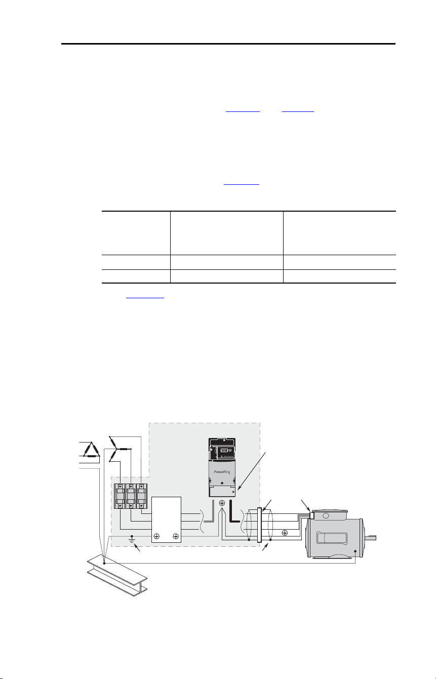
Essential Requirements for CE Compliance
Conditions 1…3 listed below must be satisfied for PowerFlex drives to
meet the requirements of EN61800-3:2004+A1:2012.
1. Grounding as described in Figure 8
. See page 17 for additional
grounding recommendations.
2. Output power, control (I/O) and signal wiring must be braided,
shielded cable with a coverage of 75% or better, metal conduit or
equivalent attenuation.
3. Allowable cable length in Table 13
is not exceeded.
Table 13 – Allowable Cable Length
(1)
See Appendix B for details on optional external filters.
(2)
Equivalent to EN55011 Class A.
(3)
Equivalent to EN55011 Class B. To meet radiated emissions requirements for
EN61800-3:2004+A1:2012 First Environment Unrestricted Distribution when
communications is used, ferrite cores need to be added to the communication lines. The
recommended core is Fair-Rite part number 0446176451 or Erocore part number
FH29.7x13x25.9/FH1300 or an equivalent core. The communication line must be
wrapped a total of three times around the core. Two cores may be needed depending on
the thickness of the wire and the core chosen. Both recommended cores are split-type
and can be added to an existing installation.
Figure 8 – Connections and Grounding
(1)
First Environment Unrestricted Distribution installations require a shielded enclosure.
Keep wire length as short as possible between the enclosure entry point and the EMI
filter.
Filter Type EN61800-3:2004+A1:2012
First Environment Restricted
Distribution or Second
Environment
(2)
EN61800-3:2004+A1:2012
First Environment Unrestricted
Distribution
(3)
External - S Type
(1)
10 m (33 ft) 1 m (3 ft)
External - L Type
(1)
100 m (328 ft) 5 m (16 ft)
R/L1
S/L2
T/L3
U/T1
V/T2
W/T3
EMI fittings and metal conduit
IP30/NEMA 1/UL Type 1
option kit
Shielded enclosure
(1)
Building structure steel
Enclosure ground connection
EMI Filter
L1'
L2'
L3'
L1
L2
L3
Shielded motor cable

42 Rockwell Automation Publication 22D-UM001F-EN-E - September 2024
Chapter 1 Installation/Wiring
EN61000-3-2
• 0.75 kW (1 HP) 240V 3-phase drives are suitable for installation on a
private low voltage power network. Installations on a public low
voltage power network may require additional external harmonic
mitigation.
• Other drive ratings meet the current harmonic requirements of
EN61000-3-2 without additional external mitigation.

Rockwell Automation Publication 22D-UM001F-EN-E - September 2024 43
Chapter 2
Start Up
This chapter describes how to start up the PowerFlex 40P Drive. To
simplify drive setup, the most commonly programmed parameters are
organized in a single Basic Program Group.
Important: See General Precautions
section before proceeding.
Before Applying Power to the Drive
❏ 1. Confirm that all inputs are connected to the correct terminals and are
secure.
❏ 2. Verify that AC line power at the disconnect device is within the rated
value of the drive.
❏ 3. Verify that any digital control power is 24 volts.
❏ 4. Verify that the Sink (SNK)/Source (SRC) Setup DIP Switch is set to
match your control wiring scheme. See Figure 5 for location.
Important: The default control scheme is Source (SRC). The Stop
terminal is jumpered to allow starting from comms. If the
control scheme is changed to Sink (SNK), the jumper must
be removed from I/O Terminals 01 and 11 and installed
between I/O Terminals 01 and 04.
❏ 5. Verify that the Stop input is present or the drive will not start.
Important: If I/O Terminal 01 is used as a stop input, the jumper
between I/O Terminals 01 and 11 must be removed.
!
ATTENTION: Power must be applied to the drive to perform the
following start-up procedures. Some of the voltages present are at
incoming line potential. To avoid electric shock hazard or damage to
equipment, only qualified service personnel should perform the
following procedure. Thoroughly read and understand the procedure
before beginning. If an event does not occur while performing this
procedure, Do Not Proceed. Remove All Power including user
supplied control voltages. User supplied voltages may exist even when
main AC power is not applied to the drive. Correct the malfunction
before continuing.
Prepare For Drive Start-Up

44 Rockwell Automation Publication 22D-UM001F-EN-E - September 2024
Chapter 2 Start Up
Applying Power to the Drive
❏ 1. Apply AC power and control voltages to the drive.
Start, Stop, Direction and Speed Control
Factory default parameter values allow the drive to be controlled from
comms. No programming is required to start, stop, change direction and
control speed directly from comms.
Important: To disable reverse operation, see A095
[Reverse Disable].
If a fault appears on power up, see Fault Descriptions
on page 117 for an
explanation of the fault code.
Variable Torque Fan/Pump Applications
For improved motor tuning performance when using a premium efficient
motor on a variable torque load, set A084
[Boost Select] to option 2
“35.0, VT”.
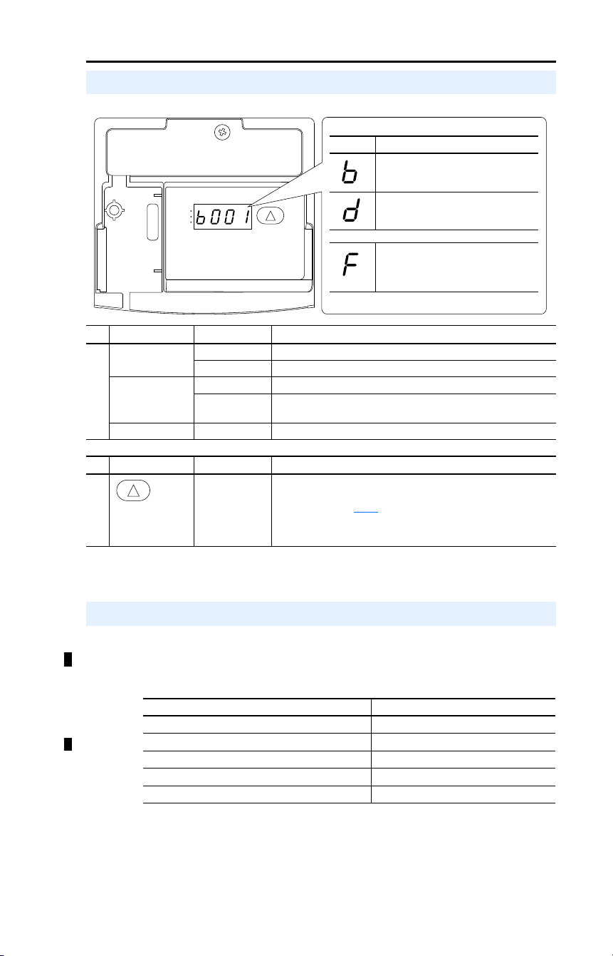
Rockwell Automation Publication 22D-UM001F-EN-E - September 2024 45
Chapter 2 Start Up
For additional drive programming and control, a DSI remote HIM or PC
programming tool (Connected Components Workbench™ or
DriveTools™ SP) should be used.
Display/Fault Reset
No. LED LED State Description
➊
Run Status Steady Red Indicates drive is running.
Flashing Red Drive has been commanded to change direction.
Direction Status Steady Red Indicates drive is running in reverse direction.
Flashing Red Drive has been commanded to change direction and motor is
decelerating to zero.
Fault Status Flashing Red Indicates drive is faulted.
No. Key Name Description
➋
Up Arrow Scroll:
Press and release to scroll through user-selectable display
parameters. See E201
[LED Display Opt] for options.
Reset:
Press and hold for three seconds to clear active fault.
RUN
REV
FAULT
➊
➋
Menu Description
Basic Display Group (View Only)
Commonly viewed drive operating
conditions.
Advanced Display Group (View Only)
Consists of advanced drive operating
conditions.
Fault Designator
Consists of list of codes for specific fault
conditions. Displayed only when fault is
present.
Drive Programming Tools
Description Catalog Number
USB Converter Module 1203-USB
Connected Components Workbench
(1)
—
DriveTools SP Software
(1)
(1)
Requires a Serial or USB Converter Module.
9303-4DTS01ENE
Remote Panel Mount, LCD Display 22-HIM-C2S
Remote Handheld, LCD Display 22-HIM-A3

46 Rockwell Automation Publication 22D-UM001F-EN-E - September 2024
Chapter 2 Start Up
Notes:

Rockwell Automation Publication 22D-UM001F-EN-E - September 2024 47
Chapter 3
Programming and Parameters
Chapter 3 provides a complete listing and description of the PowerFlex
40P parameters. Parameters are programmed (viewed/edited) using
either a DSI Remote HIM or PC programming tool (Connected
Components Workbench or DriveTools SP software), a personal
computer and a serial converter module. See Appendix
B for catalog
numbers.
To configure a drive to operate in a specific way, drive parameters may
have to be set. Three types of parameters exist:
• ENUM
ENUM parameters allow a selection from 2 or more items. Each item
is represented by a number.
• Numeric Parameters
These parameters have a single numerical value (for instance 0.1V).
• Bit Parameters
Bit parameters have four individual bits associated with features or
conditions. If the bit is 0, the feature is off or the condition is false. If
the bit is 1, the feature is on or the condition is true.
Some parameters are marked as follows.
About Parameters
= Stop drive before changing this parameter.
= 32-bit parameter. Parameters marked 32-bit will have two
parameter numbers when using RS-485 communications and
programming software.
32
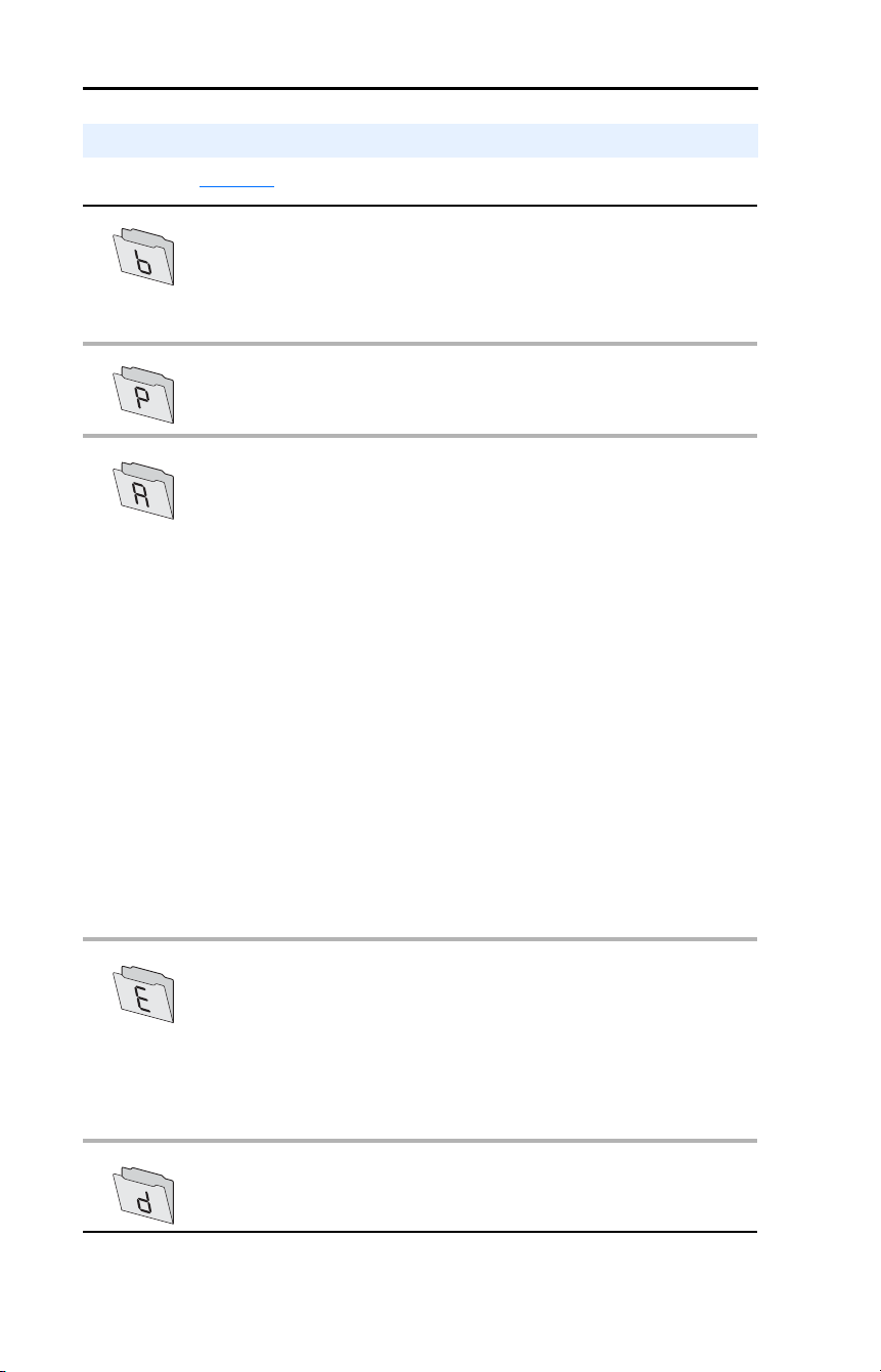
48 Rockwell Automation Publication 22D-UM001F-EN-E - September 2024
Chapter 3 Programming and Parameters
See page 112
for an alphabetical listing of parameters.
Parameter Organization
Basic Display Group
Output Freq b001
Commanded Freq b002
Output Current b003
Output Voltage b004
DC Bus Voltage b005
Drive Status b006
Fault 1 Code b007
Fault 2 Code b008
Fault 3 Code b009
Process Display b010
Control Source b012
Contrl In Status b013
Dig In Status b014
Comm Status b015
Control SW Ver b016
Drive Type b017
Elapsed Run Time b018
Testpoint Data b019
Analog In 0-10V b020
Analog In 4…20 mA b021
Output Power b022
Output Powr Fctr b023
Drive Temp b024
Counter Status b025
Timer Status b026
Stp Logic Status b028
Torque Current b029
Basic Program Group Motor NP Volts P031
Motor NP Hertz P032
Motor OL Current P033
Minimum Freq P034
Maximum Freq P035
Start Source P036
Stop Mode P037
Speed Reference P038
Accel Time 1 P039
Decel Time 1 P040
Reset To Defalts P041
Voltage Class P042
Motor OL Ret P043
Advanced Program Group
Digital In1 Sel A051
Digital In2 Sel A052
Digital In3 Sel A053
Digital In4 Sel A054
Relay Out Sel A055
Relay Out Level A056
Opto Out1 Sel A058
Opto Out1 Level A059
Opto Out2 Sel A061
Opto Out2 Level A062
Opto Out Logic A064
Analog Out Sel A065
Analog Out High A066
Accel Time 2 A067
Decel Time 2 A068
Internal Freq A069
Preset Freq 0 A070
Preset Freq 1 A071
Preset Freq 2 A072
Preset Freq 3 A073
Preset Freq 4 A074
Preset Freq 5 A075
Preset Freq 6 A076
Preset Freq 7 A077
Jog Frequency A078
Jog Accel/Decel A079
DC Brake Time A080
DC Brake Level A081
DB Resistor Sel A082
S Curve % A083
Boost Select A084
Start Boost A085
Break Voltage A086
Break Frequency A087
Maximum Voltage A088
Current Limit 1 A089
Motor OL Select A090
PWM Frequency A091
Auto Rstrt Tries A092
Auto Rstrt Delay A093
Start At PowerUp A094
Reverse Disable A095
Flying Start En A096
Compensation A097
SW Current Trip A098
Process Factor A099
Fault Clear A100
Program Lock A101
Testpoint Sel A102
Comm Data Rate A103
Comm Node Addr A104
Comm Loss Action A105
Comm Loss Time A106
Comm Format A107
Language A108
Anlg Out Setpt A109
Anlg In 0
…10V Lo A110
Anlg In 0
…10V Hi A111
Anlg In4
…20 mA Lo A112
Anlg In4
…20 mA Hi A113
Slip Hertz @ FLA A114
Process Time Lo A115
Process Time Hi A116
Bus Reg Mode A117
Current Limit 2 A118
Skip Frequency A119
Skip Freq Band A120
Stall Fault Time A121
Analog In Loss A122
10V Bipolar Enbl A123
Var PWM Disable A124
Torque Perf Mode A125
Motor NP FLA A126
Autotune A127
IR Voltage Drop A128
Flux Current Ref A129
PID Trim Hi A130
PID Trim Lo A131
PID Ref Sel A132
PID Feedback Sel A133
PID Prop Gain A134
PID Integ Time A135
PID Diff Rate A136
PID Setpoint A137
PID Deadband A138
PID Preload A139
Stp Logic 0 A140
Stp Logic 1 A141
Stp Logic 2 A142
Stp Logic 3 A143
Stp Logic 4 A144
Stp Logic 5 A145
Stp Logic 6 A146
Stp Logic 7 A147
Stp Logic Time 0 A150
Stp Logic Time 1 A151
Stp Logic Time 2 A152
Stp Logic Time 3 A153
Stp Logic Time 4 A154
Stp Logic Time 5 A155
Stp Logic Time 6 A156
Stp Logic Time 7 A157
EM Brk Off Delay A160
EM Brk On Delay A161
MOP Reset Sel A162
DB Threshold A163
PID Invert Error A164
Enhanced Program Group
LED Display Opt E201
Digital Term 3 E202
Accel Time 3 E203
Decel Time 3 E204
Accel Time 4 E205
Decel Time 4 E206
Comm Write Mode E207
Power Loss Mode E208
Half Bus Enable E209
Max Traverse E210
Traverse Inc E211
Traverse Dec E212
P Jump E213
Sync Time E214
Speed Ratio E215
Motor Fdbk Type E216
Motor NP Poles E217
Encoder PPR E218
Pulse In Scale E219
Ki Speed Loop E220
Kp Speed Loop E221
Positioning Mode E222
Find Home Freq E223
Find Home Dir E224
Encoder Pos Tol E225
Counts Per Unit E226
Step Units 0 E230
Step Units 1 E232
Step Units 2 E234
Step Units 3 E236
Step Units 4 E238
Step Units 5 E240
Step Units 6 E242
Step Units 7 E244
Pos Reg Filter E246
Pos Reg Gain E247
Enh Control Word E248
Cmd Stat Select E249
Advanced Display Group Drive Status 2 d301
Fibers Status d302
Slip Hz Meter d303
Speed Feedback d304
Encoder Speed d306
Units Traveled H d308
Units Traveled L d309
Fault 4 Code d310
Fault 5 Code d311
Fault 6 Code d312
Fault 7 Code d313
Fault 8 Code d314
Fault 9 Code d315
Fault 10 Code d316

Rockwell Automation Publication 22D-UM001F-EN-E - September 2024 49
Chapter 3 Programming and Parameters
Basic Display Group
b001 [Output Freq] Related Parameter(s): b002, b010, P034, P035, P038
Output frequency present at T1, T2, and T3 (U, V, and W).
Values Default: Read Only
Min/Max: 0.00/P035
[Maximum Freq]
Display: 0.01 Hz
b002 [Commanded Freq] Related Parameter(s): b001, b013, P034, P035, P038
Value of the active frequency command. Displays the commanded frequency even if the drive is not
running.
Important: The frequency command can come from a number of sources. See Start and Speed
Reference Control on page 38 for details.
Values Default: Read Only
Min/Max: 0.00/P035
[Maximum Freq]
Display: 0.01 Hz
b003 [Output Current]
The output current present at T1, T2, and T3 (U, V, and W).
Values Default: Read Only
Min/Max: 0.00/(Drive Rated Amps × 2)
Display: 0.01 Amps
b004 [Output Voltage] Related Parameter(s): P031, A084, A088
Output voltage present at terminals T1, T2, and T3 (U, V, and W).
Values Default: Read Only
Min/Max: 0/Drive Rated Volts
Display: 1 VAC
b005 [DC Bus Voltage]
Present DC bus voltage level.
Values Default: Read Only
Min/Max: Based on Drive Rating
Display: 1 VDC

50 Rockwell Automation Publication 22D-UM001F-EN-E - September 2024
Chapter 3 Programming and Parameters
Basic Display Group (continued)
b006 [Drive Status] Related Parameter(s): A095
Present operating condition of the drive.
Values Default: Read Only
Min/Max: 0/1
Display: 1
1 = Condition True, 0 = Condition False
Running Bit 0
Forward Bit 1
Accelerating Bit 2
Decelerating Bit 3
b007 [Fault 1 Code]
b008 [Fault 2 Code]
b009 [Fault 3 Code]
A code that represents a drive fault. The codes will appear in these parameters in the order they occur
(b007
[Fault 1 Code] = the most recent fault). Repetitive faults will only be recorded once.
See Chapter
4 for fault code descriptions.
Values Default: Read Only
Min/Max: F2/F122
Display: F1
b010 [Process Display] Related Parameter(s): b001, A099
32-bit parameter.
The output frequency scaled by A099
[Process Factor].
Values Default: Read Only
Min/Max: 0.00/9999
Display: 0.01 – 1
32
Output
Freq
Process
Factor
Process
Display
=
x
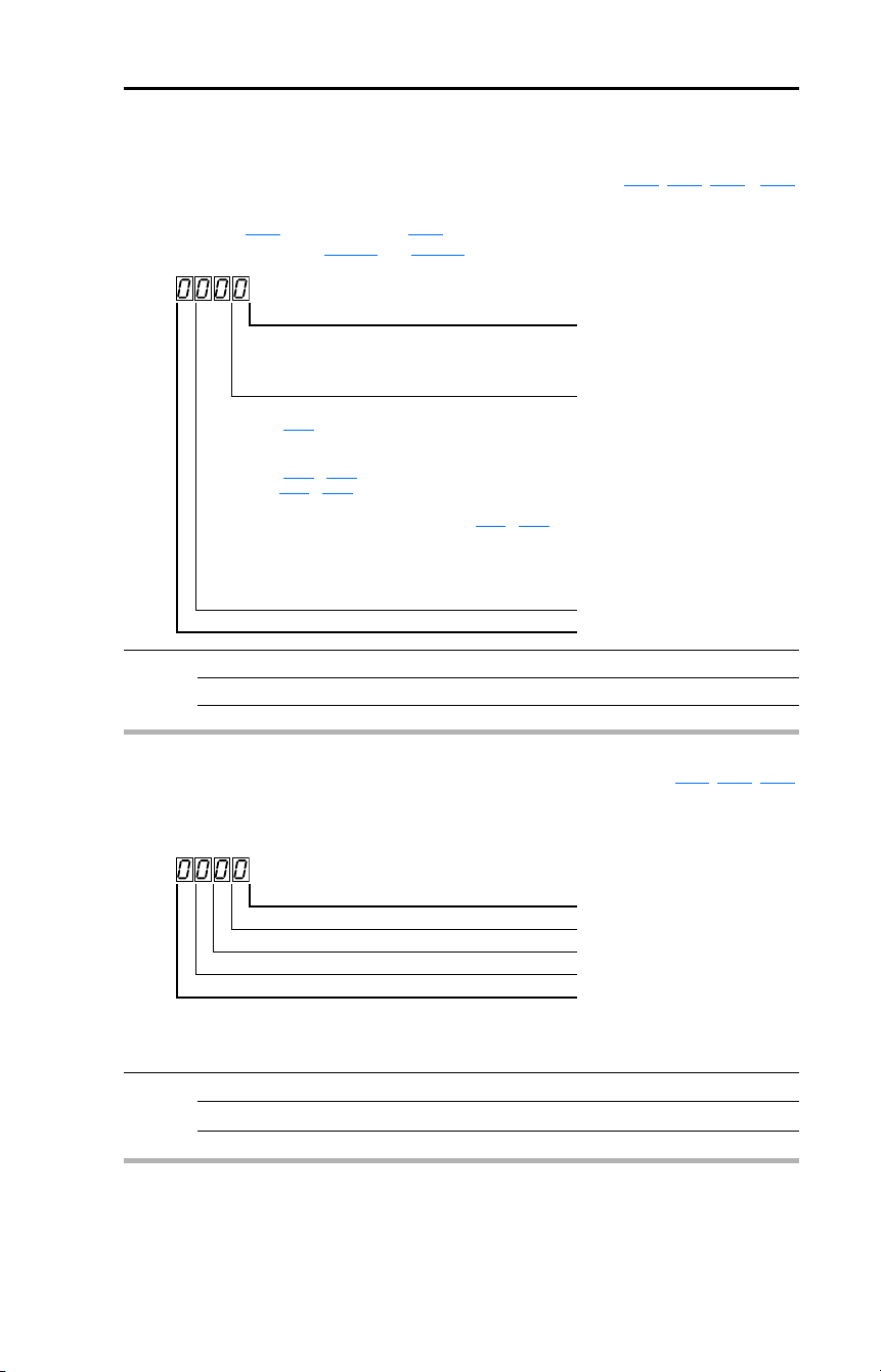
Rockwell Automation Publication 22D-UM001F-EN-E - September 2024 51
Chapter 3 Programming and Parameters
Basic Display Group (continued)
b012 [Control Source] Related Parameter(s): P036, P038, A051…A054
Displays the active source of the Start Command and Speed Command which are normally defined
by the settings of P036
[Start Source] and P038 [Speed Reference] but may be overridden by digital
inputs. See the flowcharts on page 38
and page 39 for details.
Values Default: Read Only
Min/Max: 0/112
Display: 1
Start Command Digit 1
1 = Terminal Block
2 = Communications
9 = Jogging
Speed Command Digit 3 & 2
01 = A069
[Internal Freq]
02 = 0-10V Input/Remote Potentiometer
03 = 4-20mA Input
04 = A070
…A077 [Preset Freq x]
(A051
…A053 [Digital Inx Sel] must be set to 4)
05 = RS-485 (DSI) Port
06 = StepLogic® Control (Parameters A140
…A147)
07 = Analog Input Multiply
08 = PID Control
09 = Jogging
10 = Encoder or Pulse Train Reference
11 = Positioning Control
Reserved Digit 4
b013 [Contrl In Status] Related Parameter(s): b002, P034, P035
Status of the control terminal block control inputs.
Important: Actual control commands may come from a source other than the control terminal block.
Values Default: Read Only
Min/Max: 0/1
Display: 1
1 = Input Present, 0 = Input Not Present
Start / Run FWD Input (I/O Terminal 02) Bit 0
Direction / Run REV Input (I/O Terminal 03) Bit 1
Stop Input
(1)
(I/O Terminal 01) Bit 2
(1)
The stop input must be present in order to start the drive.
When this bit is a 1 the drive can be started.
When this bit is a 0 the drive will stop.
Dynamic Brake Transistor On Bit 3
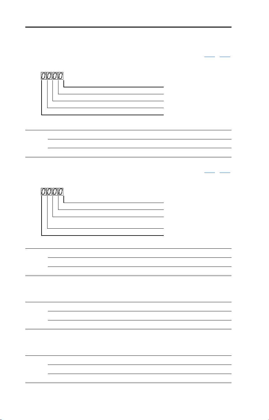
52 Rockwell Automation Publication 22D-UM001F-EN-E - September 2024
Chapter 3 Programming and Parameters
Basic Display Group (continued)
b014 [Dig In Status] Related Parameter(s): A051…A054
Status of the control terminal block digital inputs.
Values Default: Read Only
Min/Max: 0/1
Display: 1
1 = Input Present, 0 = Input Not Present
Digital In1 Sel (I/O Terminal 05) Bit 0
Digital In2 Sel (I/O Terminal 06) Bit 1
Digital In3 Sel (I/O Terminal 07) Bit 2
Digital In4 Sel (I/O Terminal 08) Bit 3
b015 [Comm Status] Related Parameter(s): A103…A107
Status of the communications ports.
Values Default: Read Only
Min/Max: 0/1
Display: 1
1 = Condition True, 0 = Condition False
Receiving Data Bit 0
Transmitting Data Bit 1
RS-485 (DSI) Based Option Connected Bit 2
(Allen-Bradley devices only.)
Communication Error Occurred Bit 3
b016 [Control SW Ver]
Main Control Board software version.
Values Default: Read Only
Min/Max: 1.00/99.99
Display: 0.01
b017 [Drive Type]
Used by Rockwell Automation field service personnel.
Values Default: Read Only
Min/Max: 1001/9999
Display: 1

Rockwell Automation Publication 22D-UM001F-EN-E - September 2024 53
Chapter 3 Programming and Parameters
Basic Display Group (continued)
b018 [Elapsed Run Time]
Accumulated time drive is outputting power. Time is displayed in 10 hour increments.
Values Default: Read Only
Min/Max: 0/9999 Hrs
Display: 1 = 10 Hrs
b019 [Testpoint Data] Related Parameter(s): A102
The present value of the function selected in A102 [Testpoint Sel].
Values Default: Read Only
Min/Max: 0/FFFF
Display: 1 Hex
b020 [Analog In 0…10V] Related Parameter(s): A110, A111
The present value of the voltage at I/O Terminal 13 (100.0% = 10 volts).
Values Default: Read Only
Min/Max: 0.0/100.0%
Display: 0.1%
b021 [Analog In 4…20 mA] Related Parameter(s): A112, A113
The present value of the current at I/O Terminal 15 (0.0% = 4 mA, 100.0% = 20 mA).
Values Default: Read Only
Min/Max: 0.0/100.0%
Display: 0.1%
b022 [Output Power]
Output power present at T1, T2, and T3 (U, V, and W).
Values Default: Read Only
Min/Max: 0.00/(Drive Rated Power × 2)
Display: 0.01 kW
b023 [Output Powr Fctr]
The angle in electrical degrees between motor voltage and motor current.
Values Default: Read Only
Min/Max: 0.0/180.0°
Display: 0.1°

54 Rockwell Automation Publication 22D-UM001F-EN-E - September 2024
Chapter 3 Programming and Parameters
Basic Display Group (continued)
b024 [Drive Temp]
Present operating temperature of the drive power section.
Values Default: Read Only
Min/Max: 0 °C (32 °F)/120 °C (248 °F)
Display: 1 °C (34 °C)
b025 [Counter Status]
The current value of the counter when counter is enabled.
Values Default: Read Only
Min/Max: 0/9999
Display: 1
b026 [Timer Status]
32-bit parameter.
The current value of the timer when timer is enabled.
Values Default: Read Only
Min/Max: 0.0/9999 Secs
Display: 0.1 Secs
32
b028 [Stp Logic Status]
When P038 [Speed Reference] is set to 6 “Stp Logic” or 9 “Positioning”, this parameter will display the
current step of the Step Logic profile as defined by parameters A140
…A147 [Stp Logic x].
Values Default: Read Only
Min/Max: 0/8
Display: 1
b029 [Torque Current]
The current value of the motor torque current.
Values Default: Read Only
Min/Max: 0.00/(Drive Rated Amps × 2)
Display: 0.01 Amps

Rockwell Automation Publication 22D-UM001F-EN-E - September 2024 55
Chapter 3 Programming and Parameters
Basic Program Group
P031 [Motor NP Volts] Related Parameter(s): b004, A084, A085, A086, A087
Stop drive before changing this parameter.
Set to the motor nameplate rated volts.
Values Default: Based on Drive Rating
Min/Max: 20/Drive Rated Volts
Display: 1 VAC
P032 [Motor NP Hertz] Related Parameter(s): A084, A085, A086, A087, A090
Stop drive before changing this parameter.
Set to the motor nameplate rated frequency.
Values Default: 60 Hz
Min/Max: 15/500 Hz
Display: 1 Hz
P033 [Motor OL Current] Related Parameter(s): A055, A058, A061, A089, A090,
A098
, A114, A118
Set to the maximum allowable motor current.
The drive will fault on an F7 Motor Overload
if the value of this parameter is exceeded by 150% for 60
seconds.
Values Default: Based on Drive Rating
Min/Max: 0.0/(Drive Rated Amps × 2)
Display: 0.1 Amps
P034 [Minimum Freq] Related Parameter(s): b001, b002, b013, P035, A085,
A086
, A087, A110, A112
Sets the lowest frequency the drive will output continuously.
Values Default: 0.00 Hz
Min/Max: 0.00/500.0 Hz
Display: 0.01 Hz
P035 [Maximum Freq] Related Parameter(s): b001, b002, b013, P034, A065,
A078
, A085, A086, A087, A111, A113
Stop drive before changing this parameter.
Sets the highest frequency the drive will output.
Values Default: 60.00 Hz
Min/Max: 0.00/500.0 Hz
Display: 0.01 Hz

56 Rockwell Automation Publication 22D-UM001F-EN-E - September 2024
Chapter 3 Programming and Parameters
Basic Program Group (continued)
P036 [Start Source] Related Parameter(s): b012, P037
Stop drive before changing this parameter.
Sets the control scheme used to start the drive and controls the behavior of I/O Terminals 01, 02, and
03. However, I/O Terminal 03 is fully programmable via E202
[Digital Term 3].
See the Start and Speed Reference Control
on page 38 for details about how other drive settings can
override the setting of this parameter.
Important: For all settings except option 3, the drive must receive a leading edge from the start input
for the drive to start after a stop input, loss of power or fault condition.
Important: I/O Terminal 01 is always a stop and must be active for the drive to run regardless of stop
source.
Options 1 “3-Wire”
(1)
I/O Terminal 01 “Stop” = Stop according to the value set in
P037
[Stop Mode].
I/O Terminal 03 “Direction”
2 “2-Wire” I/O Terminal 01 “Stop” = Coast-to-stop
I/O Terminal 03 “Run REV”
3 “2-W Lvl Sens” I/O Terminal 01 “Stop” = Coast-to-stop. Drive will restart after
a “Stop” command when:
• Stop is removed
and
• Start is held active
I/O Terminal 03 “Run REV”
4 “2-W Hi Speed” Important: There is greater potential voltage on the output
terminals when using this option.
• Outputs are kept in a ready-to-run state. The drive will
respond to a “Start” command within 10 ms.
• I/O Terminal 01 “Stop” = Coast-to-stop
• I/O Terminal 03 “Run REV”
5 “Comm Port” (Default) • Remote communications. See Appendix
C for details.
• I/O Terminal 01 “Stop” = Coast-to-stop.
6 “Momt FWD/REV” • Drive will start after a momentary input from either the
Run FWD Input (I/O Terminal 02) or the Run REV Input (I/
O Terminal 03).
• I/O Terminal 01 “Stop” = Stop according to the value set in
P037
[Stop Mode].
(1)
If I/O Terminal 01 is used as hardware enable and 3-wire control is needed, program one of the
digital inputs for the desired stop mode.
!
ATTENTION: Hazard of injury exists due to unintended operation. When
P036 [Start Source] is set to option 3, and the Run input is maintained, the
Run inputs do not need to be toggled after a Stop input for the drive to run
again. A Stop function is provided only when the Stop input is active (open).

Rockwell Automation Publication 22D-UM001F-EN-E - September 2024 57
Chapter 3 Programming and Parameters
Basic Program Group (continued)
P037 [Stop Mode] Related Parameter(s): P036, A080, A081, A082, A105, A160
Active stop mode for all stop sources [e.g. run forward (I/O Terminal 02), run reverse (I/O Terminal 03),
RS-485 port] except as noted below.
Important: I/O Terminal 01 is always a coast-to-stop input except when P036
[Start Source] is set for
“3-Wire” control. When in three wire control, I/O Terminal 01 is controlled by P037
[Stop Mode].
Hardware Enable Circuitry
By default, I/O Terminal 01 is a coast-to-stop input. The status of the input is interpreted by drive
software. If the application requires the drive to be disabled without software interpretation, a
“dedicated” hardware enable configuration can be utilized. This is accomplished by removing the
ENBL enable jumper on the control board. In this case, I/O Terminal 01 will always cause the drive to
coast to a stop regardless of the settings of P036
[Start Source] and P037 [Stop Mode].
DriveGuard Safe-Off Option (Series B)
The addition of the DriveGuard Safe-Off Option (Series B) board, when used with suitable safety
components, provides protection according to EN ISO 13849-1:2008+AC:2009; Performance Level d
(Safety Category 3) for safe-off and protection against restart.
Options 0 “Ramp, CF”
(1)
(Default) Ramp to Stop. “Stop” command clears active fault.
1 “Coast, CF”
(1)
Coast-to-Stop. “Stop” command clears active fault.
2 “DC Brake, CF”
(1)
DC Injection Braking Stop. “Stop” command clears active
fault.
3 “DCBrkAuto,CF”
(1)
DC Injection Braking Stop with Auto Shutoff.
• Standard DC Injection Braking for value set in A080
[DC
Brake Time].
OR
• Drive shuts off if the drive detects that the motor is
stopped.
“Stop” command clears active fault.
4 “Ramp” Ramp to Stop
5 “Coast” Coast-to-Stop
6 “DC Brake” DC Injection Braking Stop.
7 “DC BrakeAuto” DC Injection Braking Stop with Auto Shutoff.
• Standard DC Injection Braking for value set in A080
[DC
Brake Time].
OR
• Drive shuts off if current limit is exceeded.
8 “Ramp+EM B,CF” Ramp to Stop with EM Brake Control. “Stop” Command
clears active fault.
9 “Ramp+EM Brk” Ramp to Stop with EM Brake Control.
(1)
Stop input also clears active fault.

58 Rockwell Automation Publication 22D-UM001F-EN-E - September 2024
Chapter 3 Programming and Parameters
Basic Program Group (continued)
P038 [Speed Reference] Related Parameter(s): b001, b002, b012, b020, b021, P039,P040,
A051
…A054, A069, A070…A077, A110, A111,
A112
, A113, A123, A132, A140…A147, A150…A157
Sets the source of the speed reference to the drive.
The drive speed command can be obtained from a number of different sources. The source is
normally determined by P038
[Speed Reference]. However, when A051…A054 [Digital Inx Sel] is set
to option 2, 4, 5, 6, 11, 12, 13, 14, 15 and the digital input is active, or if A132
[PID Ref Sel] is not set
to option 0, the speed reference commanded by P038
[Speed Reference] will be overridden. See the
flowchart on page 38
for more information on speed reference control priority.
Options 1 “InternalFreq” Internal frequency command from A069
[Internal Freq]. Must
be set when using MOP function.
2 “0-10V Input” External frequency command from the 0…10V or ±10V
analog input or remote potentiometer.
3 “4-20 mA Input” External frequency command from the 4…20 mA analog
input.
4 “Preset Freq” External frequency command as defined by A070
…A077
[Preset Freq x] when A051
…A054 [Digital Inx Sel] are
programmed as “Preset Frequencies” and the digital inputs
are active.
5 “Comm Port” (Default) External frequency command from the communications port.
See Appendix
C for details.
6 “Stp Logic” External frequency command as defined by A070
…A077
[Preset Freq x] and A140
…A147 [Stp Logic x]. If Step
Logic-based positioning control is desired, select option 9
“Positioning” and adjust E222
[Positioning Mode].
7 “Anlg In Mult” External frequency command as defined by the product of the
analog inputs (shown in b020
[Analog In 0…10V] and b021
[Analog In 4-20 mA]).
[Analog In 0…10V] × [Analog In 4-20 mA] = Speed Command
Example: 100% × 50% = 50%
8 “Encoder” External frequency command directly from encoder or pulse
train input. Use E216
[Motor Fdbk Type] to select encoder
type.
9 “Positioning” External position as defined by E222
and E230…E245. See
Appendix
F for detailed information on positioning.
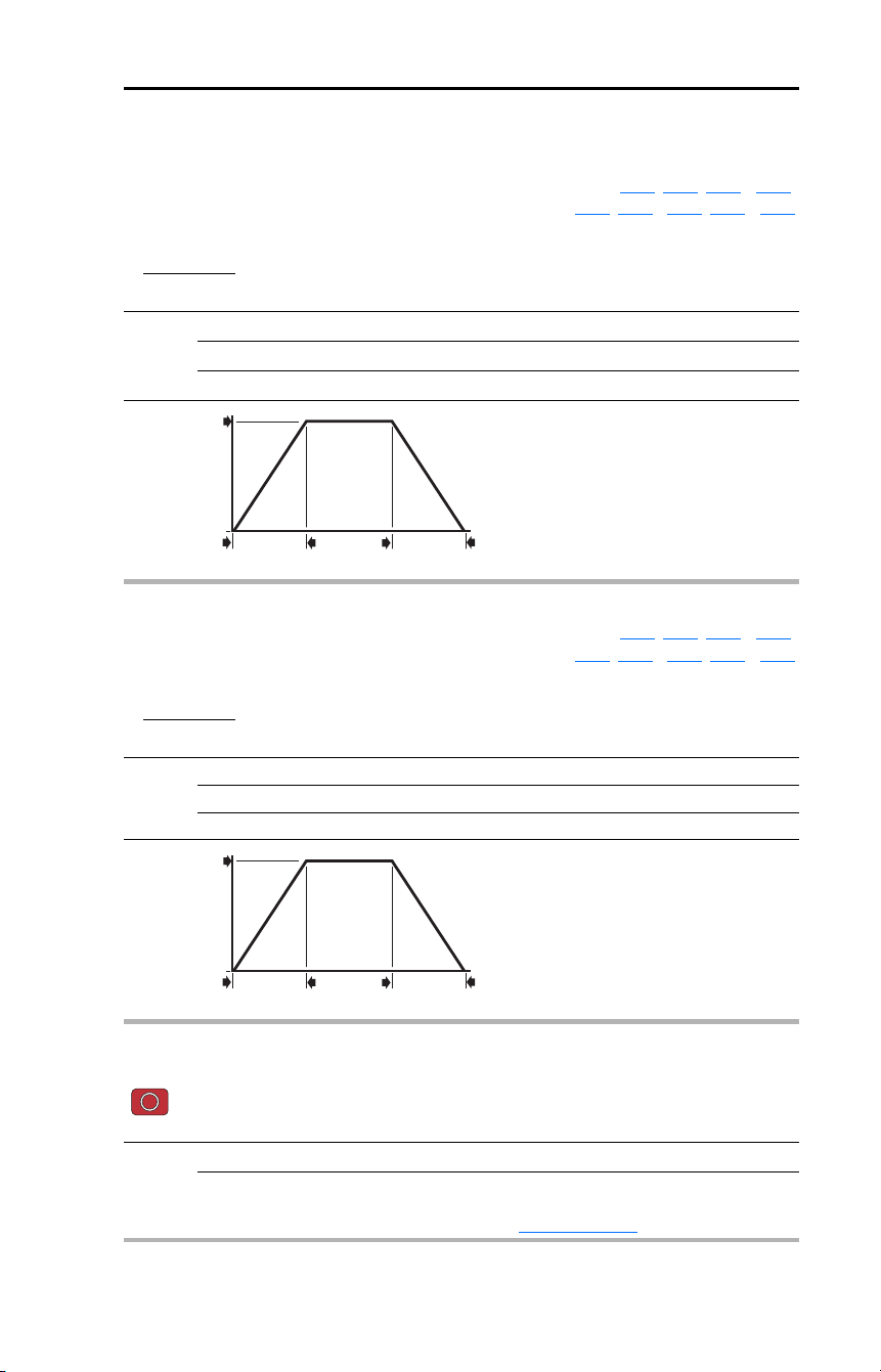
Rockwell Automation Publication 22D-UM001F-EN-E - September 2024 59
Chapter 3 Programming and Parameters
Basic Program Group (continued)
P039 [Accel Time 1] Related Parameter(s): P038, P040, A051…A054,
A067
, A070…A077, A140…A147
Sets the rate of acceleration for all speed increases.
Values Default: 10.0 Secs
Min/Max: 0.0/600.0 Secs
Display: 0.1 Secs
Maximum Freq
Accel Time
Accel Rate
=
Speed
0
Time
P035 [Maximum Freq]
P039, A067,
E203 or E205
[Accel Time x]
P040, A068,
E204 or E206
[Decel Time x]
0
Acceleration
Deceleration
P040 [Decel Time 1] Related Parameter(s): P038, P039, A051…A054,
A068
, A070…A077, A140…A147
Sets the rate of deceleration for all speed decreases.
Values Default: 10.0 Secs
Min/Max: 0.0/600.0 Secs
Display: 0.1 Secs
Maximum Freq
Decel Time
Decel Rate
=
Speed
0
Time
P035 [Maximum Freq]
P039, A067,
E203 or E205
[Accel Time x]
P040, A068,
E204 or E206
[Decel Time x]
0
Acceleration
Deceleration
P041 [Reset To Defalts]
Stop drive before changing this parameter.
Resets all parameter values to factory defaults.
Options 0 “Ready/Idle” (Default)
1 “Factory Rset” • After the reset function is complete, this parameter will set
itself back to “0”.
• Causes an F48 Params Defaulted
fault.

60 Rockwell Automation Publication 22D-UM001F-EN-E - September 2024
Chapter 3 Programming and Parameters
Basic Program Group (continued)
P042 [Voltage Class]
Stop drive before changing this parameter.
Sets the voltage class of 600V drives.
Options 2 “Low Voltage” 480V
3 “High Voltage” (Default) 600V
P043 [Motor OL Ret] Related Parameter(s): P033
Enables/disables the Motor Overload Retention function. When Enabled, the value held in the motor
overload counter is saved at power-down and restored at power-up. A change to this parameter
setting resets the counter.
Options 0 “Disabled” (Default)
1 “Enabled”

Rockwell Automation Publication 22D-UM001F-EN-E - September 2024 61
Chapter 3 Programming and Parameters
Advanced Program Group
A051 [Digital In1 Sel]
(I/O Terminal 05)
A052 [Digital In2 Sel]
(I/O Terminal 06)
A053 [Digital In3 Sel]
(I/O Terminal 07)
A054 [Digital In4 Sel]
(I/O Terminal 08)
Related Parameter(s): b012
, b014, P038, P039, P040,
A067
, A068, A070…A077, A078, A079, A118,
A140
…A147
Selects the function for the digital inputs. I/O Terminal 03 is fully programmable via E202 [Digital Term
3]. See the flowchart on page 38 for more information on speed reference control priority.
Options 0 “Not Used” Terminal has no function but can be read over network
communications via b014
[Dig In Status].
1 “Acc/Dec Sel1” If active, can determine which Accel/Decel time will be used
for all ramp rates except jog. Can be applied to one input only.
See A067
[Accel Time 2] for details. Can be used with option
28 “Acc/Dec Sel2” for additional Accel/Decel times.
2 “Jog” • When input is present, drive accelerates according to the
value set in A079
[Jog Accel/Decel] and ramps to the
value set in A078
[Jog Frequency].
• When input is removed, drive ramps to a stop according to
the value set in A079
[Jog Accel/Decel].
• A valid “Start” command will override this input.
3 “Aux Fault” When enabled, an F2 Auxiliary Input
fault will occur when the
input is removed.
4 “Preset Freq”
(A051 and A052
Default)
In Velocity mode (P038
≠ 9) selects a preset frequency. See
A070
…A077 [Preset Freq x].
In Positioning mode (P038 = 9) selects a preset frequency
and position. See E230
…E244 [Step Units x].
Important: Digital Inputs have priority for frequency and
position control when programmed as Preset Speed and are
active. See the flowchart on page 38
for more information on
speed reference control priority.
5 “Reserved”
6 “Comm Port” • When active, sets communications device as default start/
speed command source.
• Can only be tied to one input.
7 “Clear Fault”
(A053 Default)
When active, clears an active fault.
8 “RampStop,CF” Causes drive to immediately ramp to a stop regardless of how
P037
[Stop Mode] is set.
9 “CoastStop,CF” Causes drive to immediately coast to a stop regardless of
how P037
[Stop Mode] is set.
10 “DCInjStop,CF” Causes drive to immediately begin a DC Injection stop
regardless of how P037
[Stop Mode] is set.
11 “Jog Forward”
(A054 Default)
Drive accelerates to A078
[Jog Frequency] according to A079
[Jog Accel/Decel] and ramps to stop when input becomes
inactive. A valid start will override this command.
Stop drive before changing this parameter.

62 Rockwell Automation Publication 22D-UM001F-EN-E - September 2024
Chapter 3 Programming and Parameters
A051…
A054
Options
(Cont.)
12 “Jog Reverse” Drive accelerates to A078
[Jog Frequency] according to A079
[Jog Accel/Decel] and ramps to stop when input becomes
inactive. A valid start will override this command.
13 “10V In Ctrl” Selects 0-10V or ±10V control as the frequency reference.
Start source is not changed.
14 “20 mA In Ctrl” Selects 4-20 mA control as the frequency reference. Start
source is not changed.
15 “PID Disable” Disables PID function. Drive uses the next valid non-PID
speed reference.
16 “MOP Up” Increases the value of A069
[Internal Freq] at a rate of 2 Hz
per second. Default for A069 is 60 Hz.
17 “MOP Down” Decreases the value of A069
[Internal Freq] at a rate of 2 Hz
per second. Default for A069 is 60 Hz.
18 “Timer Start” Clears and starts the timer function. May be used to control
the relay or opto outputs.
19 “Counter In” Starts the counter function. May be used to control the relay
or opto outputs.
20 “Reset Timer” Clears the active timer.
21 “Reset Countr” Clears the active counter.
22 “Rset Tim&Cnt” Clears the active timer and counter.
23 “Logic In1” Logic function input number 1. May be used to control the
relay or opto outputs (see parameters A055
, A058, A061
Options 11…14). May be used in conjunction with Step Logic
parameters A140
…A147 [Stp Logic x]. Logically ORed with
E248
[Enh Control Word] bit 6 “Logic In 1”.
24 “Logic In2” Logic function input number 2. May be used to control the
relay or opto outputs (see parameters A055
, A058, A061
Options 11…14). May be used in conjunction with Step Logic
parameters A140
…A147 [Stp Logic x]. Logically ORed with
E248
[Enh Control Word] bit 7 “Logic In 2”.
25 “Current Lmt2” When active, A118
[Current Limit 2] determines the drive
current limit level.
26 “Anlg Invert” Inverts the scaling of the analog input levels set in
A110
[Anlg In 0-10V Lo] and A111 [Anlg In 0-10V Hi] or
A112
[Anlg In 4-20 mA Lo] and A113 [Anlg In 4-20 mA Hi].
27 “EM Brk Rlse” If EM brake function is enabled, this input releases the brake.
See A160
[EM Brk Off Delay] for additional information.
28 “Acc/Dec Sel2” If active, can determine which
Accel/Decel time will be used for
all ramp rates except jog. Can be
applied to one input only. Used
with option 1 “Acc/Dec Sel1” for
the Accel/Decel times listed in
this table.
!
ATTENTION: If a hazard of injury due to movement of equipment or
material exists, an auxiliary mechanical braking device must be used.
Option
Description28 1
00Acc/Dec 1
01Acc/Dec 2
10Acc/Dec 3
11Acc/Dec 4

Rockwell Automation Publication 22D-UM001F-EN-E - September 2024 63
Chapter 3 Programming and Parameters
A051…
A054
Options
(Cont.)
29 “Precharge En” Forces drive into precharge state. Typically controlled by
auxiliary contact on the disconnect at the DC input to the
drive. If this input is assigned, it must be energized for the
pre-charge relay to close and for the drive to run. If it is
de-energized, the pre-charge relay will open and the drive will
coast to a stop.
30 “Inertia Dcel” Forces drive into Inertia Ride-through state. The drive will
attempt to regulate the DC bus at the current level.
31 “Sync Enable” Must be used in order to hold the existing frequency when
Sync Time is set to enable speed synchronization. When this
input is released the drive will accelerate to the commanded
frequency in E214
[Sync Time].
32 “Traverse Dis” When an input is programmed the traverse function will be
disabled while this input is active. See E210
[Max Traverse].
33 “Home Limit” In Positioning mode, this indicates the drive is at the home
position. See Appendix
F for detailed information on
positioning.
34 “Find Home” In Positioning mode this causes the drive to return to the
Home position when a start is issued. It does this by using the
[Find Home Freq] and [Find Home Direction] until the “Home
Limit” input is activated. If it passes this point, it then runs in
the reverse direction at 1/10th the frequency of [Find Home
Freq] until the “Home Limit” is activated again. As long as this
input is active, any start command will cause the drive to
enter the homing routing. Only functions if in Positioning
mode. Once the Find Home routine has finished, the drive will
stop. See Appendix
F for detailed information on positioning.
35 “Hold Step” In Positioning mode, this input over-rides other inputs and
causes the drive to remain at its current step (running at zero
speed once it reaches its position) until released. While in
“Hold”, the drive will ignore any input command which would
normally result in a move to a new step. Timers continue to
run. Therefore, when the Hold is removed, the drive must see
any required digital inputs transition (even if they already
transitioned during the hold), but it does not reset any timer.
See Appendix
F for detailed information on positioning.
36 “Pos Redefine” In Positioning mode, this input resets the home position to the
current position of the machine. See Appendix
F for detailed
information on positioning.

64 Rockwell Automation Publication 22D-UM001F-EN-E - September 2024
Chapter 3 Programming and Parameters
Advanced Program Group (continued)
A055 [Relay Out Sel] Related Parameter(s): P033, A056, A092, A140…A147, A150…A157,
A160
, A161
Sets the condition that changes the state of the output relay contacts.
Options 0 “Ready/Fault”
(Default)
Relay changes state when power is applied. This indicates
that the drive is ready for operation. Relay returns drive to
shelf state when power is removed or a fault occurs.
1 “At Frequency” Drive reaches commanded frequency.
2 “MotorRunning” Motor is receiving power from the drive.
3 “Reverse” Drive is commanded to run in reverse direction.
4 “Motor Overld” Motor overload condition exists.
5 “Ramp Reg” Ramp regulator is modifying the programmed accel/decel
times to avoid an overcurrent or overvoltage fault from
occurring.
6 “Above Freq” • Drive exceeds the frequency (Hz) value set in A056
[Relay
Out Level].
• Use A056 to set threshold.
7 “Above Cur” • Drive exceeds the current (% Amps) value set in A056
[Relay Out Level].
• Use A056 to set threshold.
Important: Value for A056 [Relay Out Level] must be entered
in percent of drive rated output current.
8 “Above DCVolt” • Drive exceeds the DC bus voltage value set in A056
[Relay Out Level].
• Use A056 to set threshold.
9 “Retries Exst” Value set in A092
[Auto Rstrt Tries] is exceeded.
10 “Above Anlg V” • Analog input voltage (I/O Terminal 13) exceeds the value
set in A056
[Relay Out Level].
• Do not use if A123
[10V Bipolar Enbl] is set to 1 “Bi-Polar
In”.
• This parameter setting can also be used to indicate a PTC
trip point when the input (I/O Terminal 13) is wired to a
PTC and external resistor.
• Use A056 to set threshold.
11 “Logic In 1” An input is programmed as “Logic In 1” and is active.
12 “Logic In 2” An input is programmed as “Logic In 2” and is active.
13 “Logic 1 & 2” Both Logic inputs are programmed and active.
14 “Logic 1 or 2” One or both Logic inputs are programmed and one or both is
active.
15 “StpLogic Out” Drive enters Step Logic step with Digit 3 of Command Word
(A140
…A147) set to enable Step Logic output.
16 “Timer Out” • Timer has reached value set in A056
[Relay Out Level].
• Use A056 to set threshold.
17 “Counter Out” • Counter has reached value set in A056
[Relay Out Level].
• Use A056 to set threshold.
18 “Above PF Ang” • Power Factor angle has exceeded the value set in A056
[Relay Out Level].
• Use A056 to set threshold.
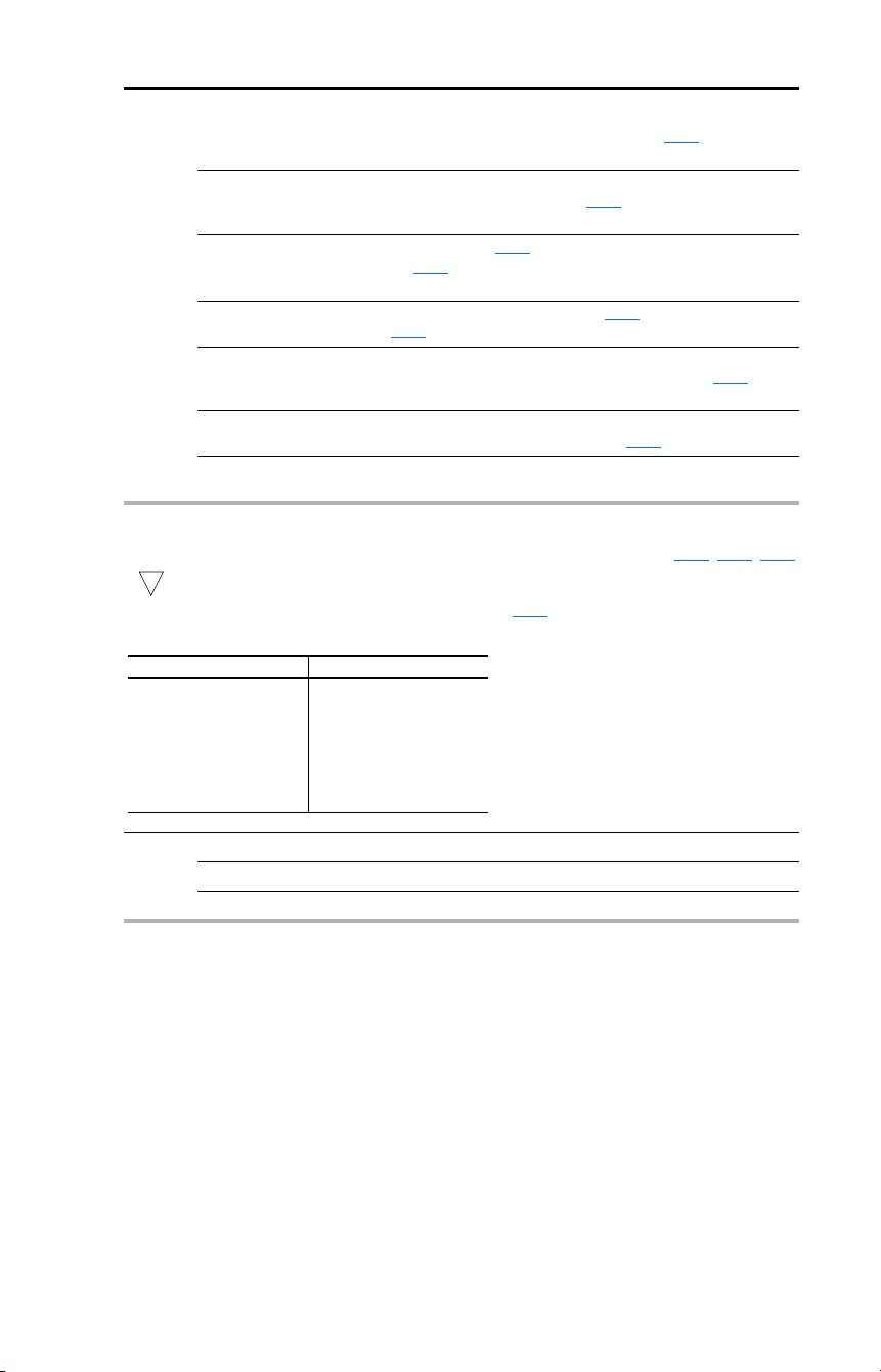
Rockwell Automation Publication 22D-UM001F-EN-E - September 2024 65
Chapter 3 Programming and Parameters
A055
Options
(Cont.)
19 “Anlg In Loss” Analog input loss has occurred. Program A122 [Analog In
Loss] for desired action when input loss occurs.
20 “ParamControl” Enables the output to be controlled over network
communications by writing to A056
[Relay Out Level].
(0 = Off, 1 = On.)
21 “NonRec Fault” • Value set in A092
[Auto Rstrt Tries] is exceeded.
• A092
[Auto Rstrt Tries] in not enabled.
• A non-resettable fault has occurred.
22 “EM Brk Cntrl” EM brake is energized. Program A160
[EM Brk Off Delay] and
A161 [EM Brk On Delay] for desired action.
23 “At Position” The drive is in Positioning mode and has reached the
commanded position. Tolerance is adjusted with E225
[Encoder Pos Tol].
24 “At Home” The drive is in Positioning mode and has reached the home
position. Tolerance is adjusted with E225
[Encoder Pos Tol].
25 “Safe-Off” The DriveGuard Safe Off option is installed and both safe-off
inputs are active.
A056 [Relay Out Level] Related Parameter(s): A055, A058, A061
32-bit parameter.
Sets the trip point for the digital output relay if the value of A055
[Relay Out Sel] is 6, 7, 8, 10, 16, 17,
18, or 20.
Values Default: 0.0
Min/Max: 0.0/9999
Display: 0.1
32
A055 Setting A056 Min/Max
6
7
8
10
16
17
18
20
0/500 Hz
0/180%
0/815 Volts
0/100%
0.1/9999 Secs
1/9999 Counts
1/180 degs
0/1

66 Rockwell Automation Publication 22D-UM001F-EN-E - September 2024
Chapter 3 Programming and Parameters
Advanced Program Group (continued)
A058 [Opto Out1 Sel] Related Parameter(s): P033, A056, A092, A140…A147, A150…A157
A061 [Opto Out2 Sel]
Determines the operation of the programmable opto outputs.
Options 0 “Ready/Fault” Opto outputs are active when power is applied. This indicates
that the drive is ready for operation. Opto outputs are inactive
when power is removed or a fault occurs.
1 “At Frequency”
(A061 Default)
Drive reaches commanded frequency.
2 “MotorRunning”
(A058 Default)
Motor is receiving power from the drive.
3 “Reverse” Drive is commanded to run in reverse direction.
4 “Motor Overld” Motor overload condition exists.
5 “Ramp Reg” Ramp regulator is modifying the programmed accel/decel
times to avoid an overcurrent or overvoltage fault from
occurring.
6 “Above Freq” • Drive exceeds the frequency (Hz) value set in A059
or
A062
[Opto Outx Level].
• Use A059 or A062 to set threshold.
7 “Above Cur” • Drive exceeds the current (% Amps) value set in A059
or
A062
[Opto Outx Level].
• Use A059 or A062 to set threshold.
Important: Value for A059
or A062 [Opto Outx Level] must be
entered in percent of drive rated output current.
8 “Above DCVolt” • Drive exceeds the DC bus voltage value set in A059
or
A062
[Opto Outx Level].
• Use A059 or A062 to set threshold.
9 “Retries Exst” Value set in A092
[Auto Rstrt Tries] is exceeded.
10 “Above Anlg V” • Analog input voltage (I/O Terminal 13) exceeds the value
set in A059
or A062 [Opto Outx Level].
• Do not use if A123
[10V Bipolar Enbl] is set to 1 “Bi-Polar
In”.
• This parameter setting can also be used to indicate a PTC
trip point when the input (I/O Terminal 13) is wired to a
PTC and external resistor.
• Use A059 or A062 to set threshold.
11 “Logic In 1” An input is programmed as “Logic In 1” and is active.
12 “Logic In 2” An input is programmed as “Logic In 2” and is active.
13 “Logic 1 & 2” Both Logic inputs are programmed and active.
14 “Logic 1 or 2” One or both Logic inputs are programmed and one or both is
active.
15 “StpLogic Out” Drive enters Step Logic step with Digit 3 of Command Word
(A140
…A147) set to enable Step Logic output.
16 “Timer Out” • Timer has reached value set in A059
or A062 [Opto Outx
Level].
• Use A059 or A062 to set threshold.
17 “Counter Out” • Counter has reached value set in A059
or A062 [Opto
Outx Level].
• Use A059 or A062 to set threshold.
Rockwell Automation Publication 22D-UM001F-EN-E - September 2024 67
Chapter 3 Programming and Parameters
A058,
A061
Options
(Cont.)
18 “Above PF Ang” • Power Factor angle has exceeded the value set in A059
or
A062
[Opto Outx Level].
• Use A059 or A062 to set threshold.
19 “Anlg In Loss” Analog input loss has occurred. Program A122
[Analog In
Loss] for desired action when input loss occurs.
20 “ParamControl” Enables the output to be controlled over network
communications by writing to A059
or A062 [Opto Outx
Level].
(0 = Off, 1 = On.)
21 “NonRec Fault” • Value set in A092
[Auto Rstrt Tries] is exceeded.
• A092
[Auto Rstrt Tries] in not enabled.
• A non-resettable fault has occurred.
22 “EM Brk Cntrl” EM brake is energized. Program A160
[EM Brk Off Delay] and
A161 [EM Brk On Delay] for desired action.
23 “At Position” The drive is in Positioning mode and has reached the
commanded position. Tolerance is adjusted with E225
[Encoder Pos Tol].
24 “At Home” The drive is in Positioning mode and has reached the home
position. Tolerance is adjusted with E225
[Encoder Pos Tol].
25 “Safe-Off” The DriveGuard Safe Off option is installed and both safe-off
inputs are active.
A059 [Opto Out1 Level]
A062 [Opto Out2 Level]
32-bit parameter.
Determines the on/off point for the opto outputs when A058
or A061 [Opto Outx Sel] is set to option 6,
7, 8, 10, 16, 17, 18, or 20.
Values Default: 0.0
Min/Max: 0.0/9999
Display: 0.1
32
A058 & A061 Setting A059 & A062 Min/Max
6
7
8
10
16
17
18
20
0/500 Hz
0/180%
0/815 Volts
0/100%
0.1/9999 Secs
1/9999 Counts
1/180 degs
0/1

68 Rockwell Automation Publication 22D-UM001F-EN-E - September 2024
Chapter 3 Programming and Parameters
Advanced Program Group (continued)
A064 [Opto Out Logic]
Determines the logic (Normally Open/NO or Normally Closed/NC) of the opto outputs.
Values Default: 0
Min/Max: 0/3
Display: 1
A064 Option Opto Out1 Logic Opto Out2 Logic
0
1
2
3
NO (Normally Open)
NC (Normally Closed)
NO (Normally Open)
NC (Normally Closed)
NO (Normally Open)
NO (Normally Open)
NC (Normally Closed)
NC (Normally Closed)
A065 [Analog Out Sel] Related Parameter(s): P035, A066
Sets the analog output signal mode (0-10V, 0-20 mA, or 4-20 mA). The output is used to provide a
signal that is proportional to several drive conditions.
Values Default: 0
Min/Max: 0/20
Display: 1
Option
Output
Range
Minimum Output
Value
Maximum Output Value
A066 [Analog Out High]
DIP Switch
Position
Related
Parameter
0 “OutFreq 0-10” 0-10V 0V = 0 Hz P035 [Maximum Freq] 0-10V
b001
1 “OutCurr 0-10” 0-10V 0V = 0 Amps 200% Drive Rated Output Current 0-10V
b003
2 “OutVolt 0-10” 0-10V 0V = 0 Volts 120% Drive Rated Output Volts 0-10V
b004
3 “OutPowr 0-10” 0-10V 0V = 0 kW 200% Drive Rated Power 0-10V
b022
4 “TstData 0-10” 0-10V 0V = 0000 65535 (Hex FFFF) 0-10V
b019
5 “OutFreq 0-20” 0-20mA 0 mA = 0 Hz P035 [Maximum Freq] 0-20mA
b001
6 “OutCurr 0-20” 0-20mA 0 mA = 0 Amps 200% Drive Rated Output Current 0-20mA
b003
7 “OutVolt 0-20” 0-20mA 0 mA = 0 Volts 120% Drive Rated Output Volts 0-20mA
b004
8 “OutPowr 0-20” 0-20mA 0 mA = 0 kW 200% Drive Rated Power 0-20mA
b022
9 “TstData 0-20” 0-20mA 0 mA = 0000 65535 (Hex FFFF) 0-20mA
b019
10 “OutFreq 4-20” 4-20mA 4 mA = 0 Hz P035 [Maximum Freq] 0-20mA
b001
11 “OutCurr 4-20” 4-20mA 4 mA = 0 Amps 200% Drive Rated Output Current 0-20mA
b003
12 “OutVolt 4-20” 4-20mA 4 mA = 0 Volts 120% Drive Rated Output Volts 0-20mA
b004
13 “OutPowr 4-20” 4-20mA 4 mA = 0 kW 200% Drive Rated Power 0-20mA
b022
14 “TstData 4-20” 4-20mA 4 mA = 0000 65535 (Hex FFFF) 0-20mA
b019
15 “OutTorq 0-10” 0-10V 0V = 0 Amps 200% Drive Rated FLA 0-10V
b029
16 “OutTorq 0-20” 0-20mA 0 mA = 0 Amps 200% Drive Rated FLA 0-20mA
b029
17 “OutTorq 4-20” 4-20mA 4 mA = 0 Amps 200% Drive Rated FLA 0-20mA
b029
18 “Setpnt 0-10” 0-10V 0V = 0% 100.0% Setpoint Setting 0-10V
A109
19 “Setpnt 0-20” 0-20 mA 0 mA = 0% 100.0% Setpoint Setting 0-20 mA
A109
20 “Setpnt 4-20” 4-20 mA 4 mA = 0% 100.0% Setpoint Setting 0-20 mA
A109
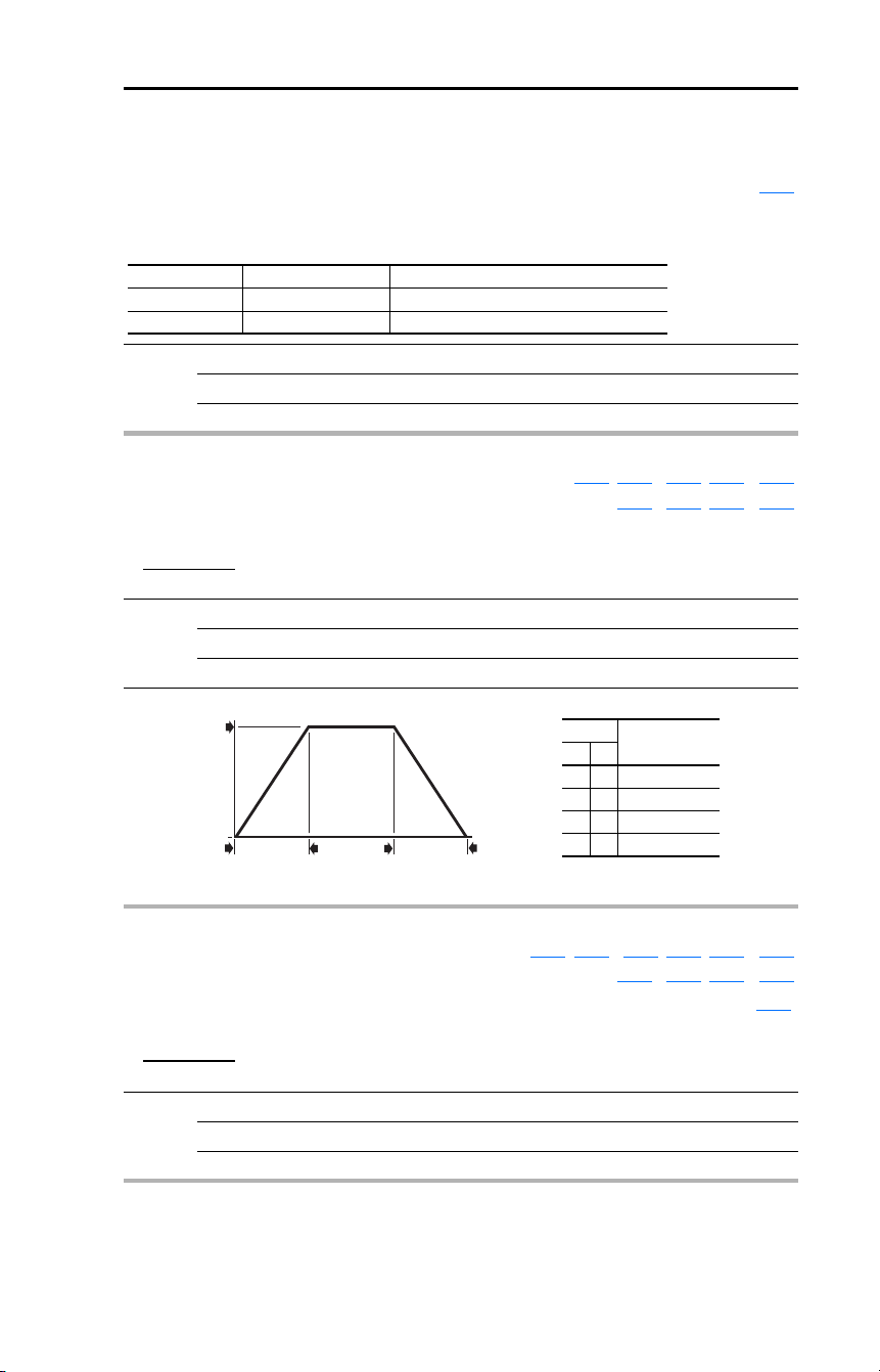
Rockwell Automation Publication 22D-UM001F-EN-E - September 2024 69
Chapter 3 Programming and Parameters
Advanced Program Group (continued)
A066 [Analog Out High] Related Parameter(s): A065
Scales the Maximum Output Value for the A065 [Analog Out Sel] source setting.
Examples:
Values Default: 100%
Min/Max: 0/800%
Display: 1%
A066 Setting A065 Setting A065 Max. Output Value
50% 1 “OutCurr 0-10” 5V for 200% Drive Rated Output Current
90% 8 “OutPowr 0-20” 18mA for 200% Drive Rated Power
A067 [Accel Time 2] Related Parameter(s): P039, A051…A054, A070…A077
A140…A147, E203…E206
When active, sets the rate of acceleration for all speed increases except jog.
Values Default: 20.0 Secs
Min/Max: 0.0/600.0 Secs
Display: 0.1 Secs
Maximum Freq
Accel Time
Accel Rate
=
Option
Description28 1
00Acc/Dec 1
01Acc/Dec 2
10Acc/Dec 3
11Acc/Dec 4
Speed
0
Time
P035 [Maximum Freq]
P039, A067,
E203 or E205
[Accel Time x]
P040, A068,
E204 or E206
[Decel Time x]
0
Acceleration
Deceleration
A068 [Decel Time 2] Related Parameter(s): P040, A051…A054, A067, A070…A077
A140…A147, E203…E206
When active, sets the rate of deceleration for all speed decreases except jog. See the graphic at A067
[Accel Time 2].
Values Default: 20.0 Secs
Min/Max: 0.0/600.0 Secs
Display: 0.1 Secs
Maximum Freq
Decel Time
Decel Rate
=

70 Rockwell Automation Publication 22D-UM001F-EN-E - September 2024
Chapter 3 Programming and Parameters
Advanced Program Group (continued)
A069 [Internal Freq] Related Parameter(s): P038, A162
Provides the frequency command to the drive when P038 [Speed Reference] is set to 1 “InternalFreq”.
When enabled, this parameter will change the frequency command in “real time”.
If A051
…A054 [Digital Inx Sel] is set to 16 “MOP Up” or 17 “MOP Down” this parameter acts as the
MOP frequency reference.
Values Default: 60.00 Hz
Min/Max: 0.00/500.0 Hz
Display: 0.01 Hz

Rockwell Automation Publication 22D-UM001F-EN-E - September 2024 71
Chapter 3 Programming and Parameters
Advanced Program Group (continued)
A070 [Preset Freq 0]
(1)
A071 [Preset Freq 1]
A072 [Preset Freq 2]
A073 [Preset Freq 3]
A074 [Preset Freq 4]
A075 [Preset Freq 5]
A076 [Preset Freq 6]
A077 [Preset Freq 7]
Related Parameter(s): P038, P039, P040, A051…A053,
A067
, A068, A140…A147, A150…A157
Values A070 Default:
(1)
A071 Default:
A072 Default:
A073 Default:
A074 Default:
A075 Default:
A076 Default:
A077 Default:
0.00 Hz
5.00 Hz
10.00 Hz
20.00 Hz
30.00 Hz
40.00 Hz
50.00 Hz
60.00 Hz
Min/Max: 0.00/500.0 Hz
Display: 0.01 Hz
Provides a fixed frequency command value when A051
…A053 [Digital Inx Sel] is set to 4 “Preset
Freq”.
An active preset input will override speed command as shown in the flowchart on page 38
.
(1)
To activate A070…A077 in Velocity mode, set P038 [Speed Reference] to option 4 “Preset Freq”.
In Positioning mode, set P038
[Speed Reference] to option 9 “Positioning” and E222 [Positioning
Mode] to option 1 “Preset Input”.
Input State
of Digital In 1
(I/O Terminal 05
when A051 = 4)
Input State
of Digital In 2
(I/O Terminal 06
when A052 = 4)
Input State
of Digital In 3
(I/O Terminal 07
when A053 = 4)
Freq
Source
Position
Source
(when
P038 = 9) Accel / Decel Parameter Used
(2)
0 0 0 A070 E230 [Accel Time 1] / [Decel Time 1]
1 0 0 A071 E232 [Accel Time 1] / [Decel Time 1]
0 1 0 A072 E234 [Accel Time 2] / [Decel Time 2]
1 1 0 A073 E236 [Accel Time 2] / [Decel Time 2]
0 0 1 A074 E238 [Accel Time 1] / [Decel Time 1]
1 0 1 A075 E240 [Accel Time 1] / [Decel Time 1]
0 1 1 A076 E242 [Accel Time 2] / [Decel Time 2]
1 1 1 A077 E244 [Accel Time 2] / [Decel Time 2]
(2)
When a Digital Input is set to “Accel 2 & Decel 2”, and the input is active, that input overrides the settings in this
table.
A078 [Jog Frequency]
Related Parameter(s): P035, A051…A054, A079
Sets the output frequency when a jog command is issued.
Values Default: 10.00 Hz
Min/Max: 0.00/[Maximum Freq]
Display: 0.01 Hz
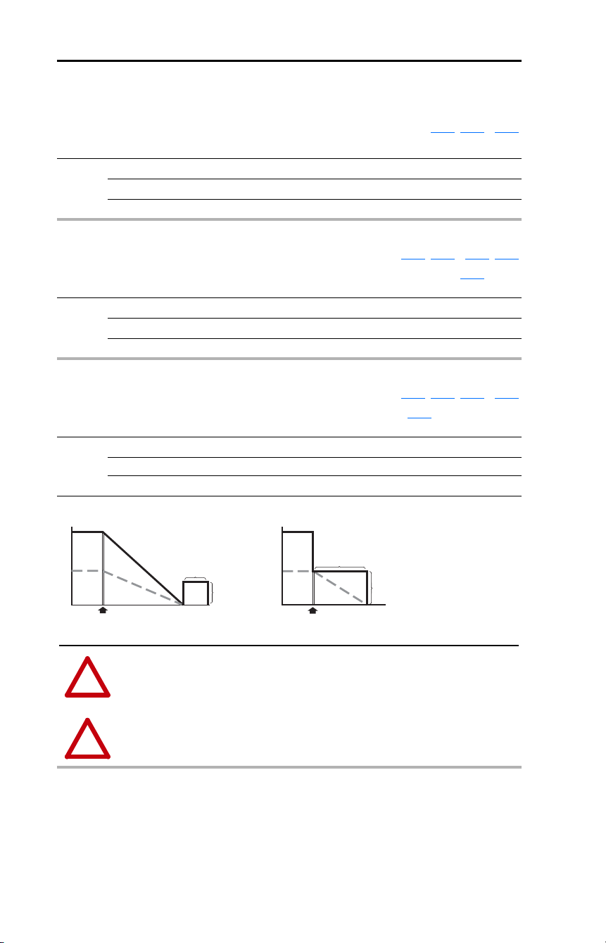
72 Rockwell Automation Publication 22D-UM001F-EN-E - September 2024
Chapter 3 Programming and Parameters
Advanced Program Group (continued)
A079 [Jog Accel/Decel] Related Parameter(s): A078, A051…A054
Sets the acceleration and deceleration time when a jog command is issued.
Values Default: 10.0 Secs
Min/Max: 0.1/600.0 Secs
Display: 0.1 Secs
A080 [DC Brake Time] Related Parameter(s): P037, A051…A054, A081
Sets the length of time that DC brake current is “injected” into the motor. See parameter A081 [DC
Brake Level].
Values Default: 0.0 Secs
Min/Max: 0.0/99.9 Secs (A setting of 99.9 = Continuous)
Display: 0.1 Secs
A081 [DC Brake Level] Related Parameter(s): P037, A080, A051…A054
Defines the maximum DC brake current, in amps, applied to the motor when P037 [Stop Mode] is set
to either option 4 “Ramp” or 6 “DC Brake”.
Values Default: Drive Rated Amps × 0.05
Min/Max: 0.0/(Drive Rated Amps × 1.8)
Display: 0.1 Amps
DC Injection Braking Mode
Volts/Speed
Voltage
Time
Stop Command
Speed
[DC Brake Level]
[DC Brake Time]
Volts/Speed
Ramp-to-Stop Mode
Time
Stop Command
[DC Brake Level]
[DC Brake Time]
Voltage
Speed
!
ATTENTION: If a hazard of injury due to movement of equipment or material exists, an
auxiliary mechanical braking device must be used.
!
ATTENTION: This feature should not be used with synchronous or permanent magnet
motors. Motors may be demagnetized during braking.
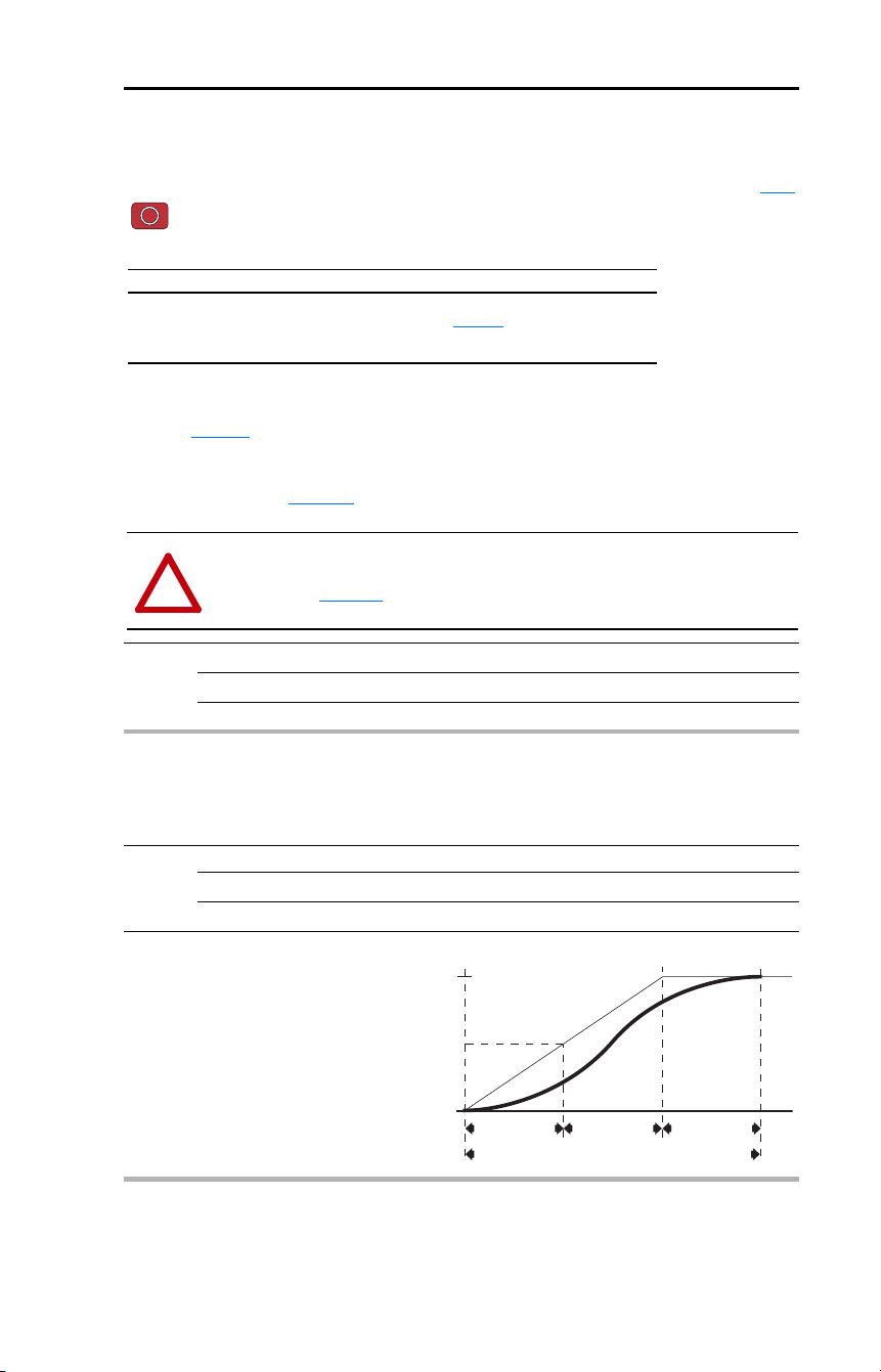
Rockwell Automation Publication 22D-UM001F-EN-E - September 2024 73
Chapter 3 Programming and Parameters
Advanced Program Group (continued)
A082 [DB Resistor Sel] Related Parameter(s): P037
Stop drive before changing this parameter.
Enables/disables external dynamic braking.
The drive is able to provide full braking indefinitely. Braking power is limited by the external DB
resistor. When this parameter is set to 1 “Normal RA Res” and an appropriate resistor is used (see
selection Table 21
), the drive provides calculated resistor overload protection. However, the drive
cannot protect against a brake IGBT failure.
For more information on external dynamic brake kits, see the External Dynamic Brake Kit Installation
Instructions, publication RA-IN004
.
Values Default: 0
Min/Max: 0/99
Display: 1
Setting Min/Max
0
1
2
3…99
“Disabled”
“Normal RA Res” (5% Duty Cycle) – See Table 21
.
“NoProtection” (100% Duty Cycle)
“x%Duty Cycle” Limited (3…99% of Duty Cycle)
!
ATTENTION: A risk of fire exists if external braking resistors are not protected. The
external resistor package must be self-protected from over temperature or the protective
circuit shown in Figure 15
, or equivalent, must be supplied.
A083 [S Curve %]
Sets the percentage of acceleration or deceleration time that is applied to the ramp as S Curve. Time
is added, 1/2 at the beginning and 1/2 at the end of the ramp.
Values Default: 0% (Disabled)
Min/Max: 0/100%
Display: 1%
Example:
Accel Time = 10 Seconds
S Curve Setting = 50%
S Curve Time = 10 × 0.5 = 5 Seconds
Total Time = 10 + 5 = 15 Seconds
1/2 S Curve Time
2.5 Seconds
Total Time to Accelerate = Accel Time + S Curve Time
50% S Curve
Target
Target/2
Accel Time
10 Seconds
1/2 S Curve Time
2.5 Seconds
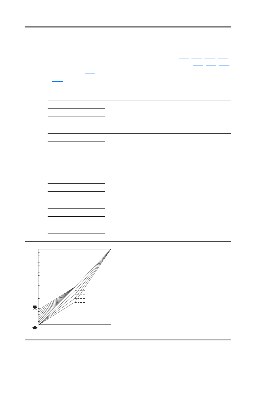
74 Rockwell Automation Publication 22D-UM001F-EN-E - September 2024
Chapter 3 Programming and Parameters
Advanced Program Group (continued)
A084 [Boost Select] Related Parameter(s): b004, P031, P032, A085,
A086
, A087, A125
Sets the boost voltage (% of P031 [Motor NP Volts]) and redefines the Volts per Hz curve.
Active when A125
[Torque Perf Mode] = 0 “V/Hz”.
Drive may add additional voltage unless Option 5 is selected.
Options 0 “Custom V/Hz”
1 “30.0, VT”
Variable Torque (Typical fan/pump curves.)
2 “35.0, VT”
3 “40.0, VT”
4 “45.0, VT”
5 “0.0 no IR”
Constant Torque
6 “0.0”
7 “2.5, CT”
[Default for
4.0, 5.5, 7.5, & 11 kW
(5.0, 7.5, 10 & 15 HP)
Drives]
8 “5.0, CT” (Default)
9 “7.5, CT”
10 “10.0, CT”
11 “12.5, CT”
12 “15.0, CT”
13 “17.5, CT”
14 “20.0, CT”
% P032 [Motor NP Hertz]
% P031 [Motor NP Volts]
100
50
1/2 [Motor NP Volts]
1/2
[Motor NP Hertz]
4
3
2
1
050100
Settings
5-14
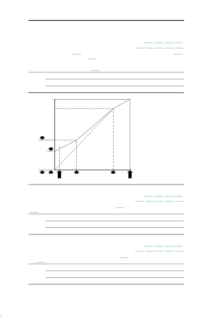
Rockwell Automation Publication 22D-UM001F-EN-E - September 2024 75
Chapter 3 Programming and Parameters
Advanced Program Group (continued)
A085 [Start Boost] Related Parameter(s): P031, P032, P034, P035,
A084
, A086, A087, A088, A125
Sets the boost voltage (% of P031 [Motor NP Volts]) and redefines the Volts per Hz curve when A084
[Boost Select] = 0 “Custom V/Hz” and A125
[Torque Perf Mode] = 0 “V/Hz”.
Drive may add additional voltage unless A084
[Boost Select] = 5 “0.0 no IR”.
Values Default: 2.5%
Min/Max: 0.0/25.0%
Display: 0.1%
Frequency
Voltage
A087 [Break Frequency] P032 [Motor NP Hertz]
P035 [Maximum Freq]
A085 [Start Boost]
P031 [Motor NP Volts]
A088 [Maximum Voltage]
A086 [Break Voltage]
A034 [Minimum Freq]
A086 [Break Voltage] Related Parameter(s): P031, P032, P034, P035,
A084
, A085, A087, A088, A125
Sets the frequency where break voltage is applied when A084 [Boost Select] = 0 “Custom V/Hz” and
A125
[Torque Perf Mode] = 0 “V/Hz”
Values Default: 25.0%
Min/Max: 0.0/100.0%
Display: 0.1%
A087 [Break Frequency] Related Parameter(s): P031, P032, P034, P035,
A084
, A085, A086, A088, A125
Sets the frequency where break frequency is applied when A084 [Boost Select] = 0 “Custom V/Hz”
and A125
[Torque Perf Mode] = 0 “V/Hz”
Values Default: 15.0 Hz
Min/Max: 0.0/500.0 Hz
Display: 0.1 Hz
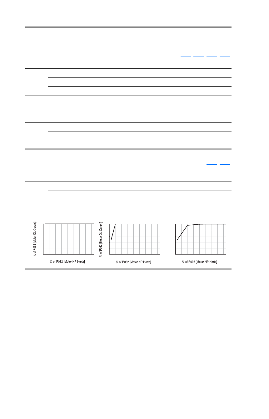
76 Rockwell Automation Publication 22D-UM001F-EN-E - September 2024
Chapter 3 Programming and Parameters
Advanced Program Group (continued)
A088 [Maximum Voltage] Related Parameter(s): b004, A085, A086, A087
Sets the highest voltage the drive will output.
Values Default: Drive Rated Volts
Min/Max: 20/Drive Rated Volts
Display: 1 VAC
A089 [Current Limit 1] Related Parameter(s): P033, A118
Maximum output current allowed before current limiting occurs.
Values Default: Drive Rated Amps × 1.5
Min/Max: 0.1/Drive Rated Amps × 1.8
Display: 0.1 Amps
A090 [Motor OL Select] Related Parameter(s): P032, P033
Drive provides Class 10 motor overload protection. Settings 0…2 select the derating factor for the I
2
t
overload function.
Options 0 “No Derate” (Default)
1 “Min Derate”
2 “Max Derate”
Min D
e
r
a
t
e
0
80
1
00
60
4
0
2
0
N
o
D
e
r
a
t
e
0
80
1
00
60
4
0
2
0
%
of P033
[
Motor OL Curent
]
M
a
x D
e
r
a
t
e
0
80
1
00
60
4
0
2
0
0
2
00
17
5
1
50
12
5
1
00
7
5
50
2
5
0
2
00
17
5
1
50
12
5
1
00
7
5
50
2
5
0
2
00
17
5
1
50
12
5
1
00
7
5
50
2
5
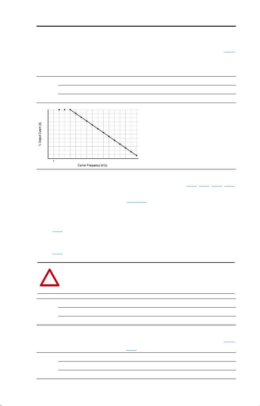
Rockwell Automation Publication 22D-UM001F-EN-E - September 2024 77
Chapter 3 Programming and Parameters
Advanced Program Group (continued)
A091 [PWM Frequency] Related Parameter(s): A124
Sets the carrier frequency for the PWM output waveform. The chart below provides derating
guidelines based on the PWM frequency setting.
Important: Ignoring derating guidelines can cause reduced drive performance.
Values Default: 4.0 kHz
Min/Max: 2.0/16.0 kHz
Display: 0.1 kHz
68
84
88
80
7
6
96
1
00
92
72
64
60
56
52
8
7
6
5
4
3
2
1
1
5
14
1
6
1
3
12
11
1
0
9
A092 [Auto Rstrt Tries] Related Parameter(s): A055, A058, A061, A093
Sets the maximum number of times the drive attempts to reset a fault and restart.
For information on faults and fault codes, see Chapter
4.
Clear a Type 1 fault and restart the drive.
1. Set A092 [Auto Rstrt Tries] to a value other than “0”.
2. Set A093
[Auto Rstrt Delay] to a value other than “0”.
Clear an OverVoltage, UnderVoltage or Heatsink OvrTmp fault without restarting the drive.
1. Set A092 [Auto Rstrt Tries] to a value other than “0”.
2. Set A093
[Auto Rstrt Delay] to “0”.
Values Default: 0
Min/Max: 0/9
Display: 1
!
ATTENTION: Equipment damage and/or personal injury may result if this parameter is
used in an inappropriate application. Do not use this function without considering
applicable local, national and international codes, standards, regulations or industry
guidelines.
A093 [Auto Rstrt Delay] Related Parameter(s): A092
Sets the time between restart attempts when A092 [Auto Rstrt Tries] is set to a value other than zero.
Values Default: 1.0 Secs
Min/Max: 0.0/120.0 Secs
Display: 0.1 Secs

78 Rockwell Automation Publication 22D-UM001F-EN-E - September 2024
Chapter 3 Programming and Parameters
Advanced Program Group (continued)
A094 [Start At PowerUp]
Stop drive before changing this parameter.
Enables/disables a feature that allows a Start or Run command to automatically cause the drive to
resume running at commanded speed after drive input power is restored. Requires a digital input
configured for Run or Start and a valid start contact.
This parameter will not function if parameter P036
[Start Source] is set to 4 “2-W High Speed”.
Options 0 “Disabled” (Default)
1 “Enabled”
!
ATTENTION: Equipment damage and/or personal injury may result if this parameter is
used in an inappropriate application. Do not use this function without considering
applicable local, national and international codes, standards, regulations or industry
guidelines.
A095 [Reverse Disable] Related Parameter(s): b006
Stop drive before changing this parameter.
Enables/disables the function that allows the direction of motor rotation to be changed. The reverse
command may come from a digital command or a serial command. All reverse inputs including
two-wire Run Reverse will be ignored with reverse disabled.
Options 0 “Rev Enabled” (Default)
1 “Rev Disabled”
A096 [Flying Start En]
Sets the condition that allows the drive to reconnect to a spinning motor at actual RPM.
Important: Do not use this feature with permanent magnet motors.
Options 0 “Disabled” (Default)
1 “Enabled”
A097 [Compensation]
Enables/disables correction options that may improve problems with motor instability.
Options 0 “Disabled”
1 “Electrical” (Default) Some drive/motor combinations have inherent instabilities
which are exhibited as non-sinusodial motor currents. This
setting attempts to correct this condition.
2 “Mechanical” Some motor/load combinations have mechanical resonances
which can be excited by the drive current regulator. This
setting slows down the current regulator response and
attempts to correct this condition.
3 “Both”

Rockwell Automation Publication 22D-UM001F-EN-E - September 2024 79
Chapter 3 Programming and Parameters
Advanced Program Group (continued)
A098 [SW Current Trip] Related Parameter(s): P033
Enables/disables a software instantaneous (within 100 ms) current trip.
Values Default: 0.0 (Disabled)
Min/Max: 0.0/(Drive Rated Amps × 2)
Display: 0.1 Amps
A099 [Process Factor] Related Parameter(s): b010
Scales the output frequency value displayed by b010 [Process Display].
Values Default: 30.0
Min/Max: 0.1/999.9
Display: 0.1
Output
Freq
Process
Factor
Process
Display
=
x
A100 [Fault Clear]
Stop drive before changing this parameter.
Resets a fault and clears the fault queue. Used primarily to clear a fault over network communications.
Options 0 “Ready/Idle” (Default)
1 “Reset Fault”
2 “Clear Buffer” (Parameters b007
…b009 and d310…d316 [Fault x Code])
A101 [Program Lock]
Protects parameters against change by unauthorized personnel with a 4-digit password.
Options 0 “Unlocked” (Default)
1 “Locked”
A102 [Testpoint Sel] Related Parameter(s): b019
Used by Rockwell Automation field service personnel.
Values Default: 400
Min/Max: 400/FFFF
Display: 1 Hex

80 Rockwell Automation Publication 22D-UM001F-EN-E - September 2024
Chapter 3 Programming and Parameters
Advanced Program Group (continued)
A103 [Comm Data Rate] Related Parameter(s): b015
Sets the serial port rate for the RS-485 (DSI) port.
Important: Power to drive must be cycled before any changes will affect drive operation.
Options 0 “1200”
1 “2400”
2 “4800”
3 “9600” (Default)
4 “19.2K”
5 “38.4K”
A104 [Comm Node Addr] Related Parameter(s): b015
Sets the drive node address for the RS-485 (DSI) port if using a network connection.
Important: Power to drive must be cycled before any changes will affect drive operation.
Values Default: 100
Min/Max: 1/247
Display: 1
A105 [Comm Loss Action] Related Parameter(s): b015, P037, A106
Selects the drive’s response to a loss of the communication connection or excessive communication
errors.
Options 0 “Fault” (Default) Drive will fault on an F81
Comm Loss and coast-to-stop.
1 “Coast Stop” Stops drive via coast-to-stop.
2 “Stop” Stops drive via P037
[Stop Mode] setting.
3 “Continu Last” Drive continues operating at communication commanded
speed saved in RAM.
A106 [Comm Loss Time] Related Parameter(s): b015, A105
Sets the time that the drive will remain in communication loss before implementing the option selected
in A105
[Comm Loss Action].
Values Default: 5.0 Secs
Min/Max: 0.1/60.0 Secs
Display: 0.1 Secs

Rockwell Automation Publication 22D-UM001F-EN-E - September 2024 81
Chapter 3 Programming and Parameters
Advanced Program Group (continued)
A107 [Comm Format] Related Parameter(s): b015
Selects the protocol (RTU only), data bits (8 data bits only), parity (None, Even, Odd), and stop bits (1
stop bit only) used by the RS-485 port on the drive.
See Appendix
C for details on using the drive communication features.
Important: Power to drive must be cycled before any changes will affect drive operation.
Options 0 “RTU 8-N-1” (Default)
1 “RTU 8-E-1”
2 “RTU 8-O-1”
3 “RTU 8-N-2”
4 “RTU 8-E-2”
5 “RTU 8-O-2”
A108 [Language]
Selects the language displayed by the remote communications option.
Options 1 “English” (Default)
2 “Français”
3 “Español”
4 “Italiano”
5 “Deutsch”
6 “Reserved”
7 “Português”
8 “Reserved”
9 “Reserved”
10 “Nederlands”
A109 [Anlg Out Setpt] Related Parameter(s): A065
When A065 [Analog Out Sel] is set to option 18, 19, or 20, this parameter sets the percentage of
analog output desired.
Values Default: 0.0%
Min/Max: 0.0/100.0%
Display: 0.1%
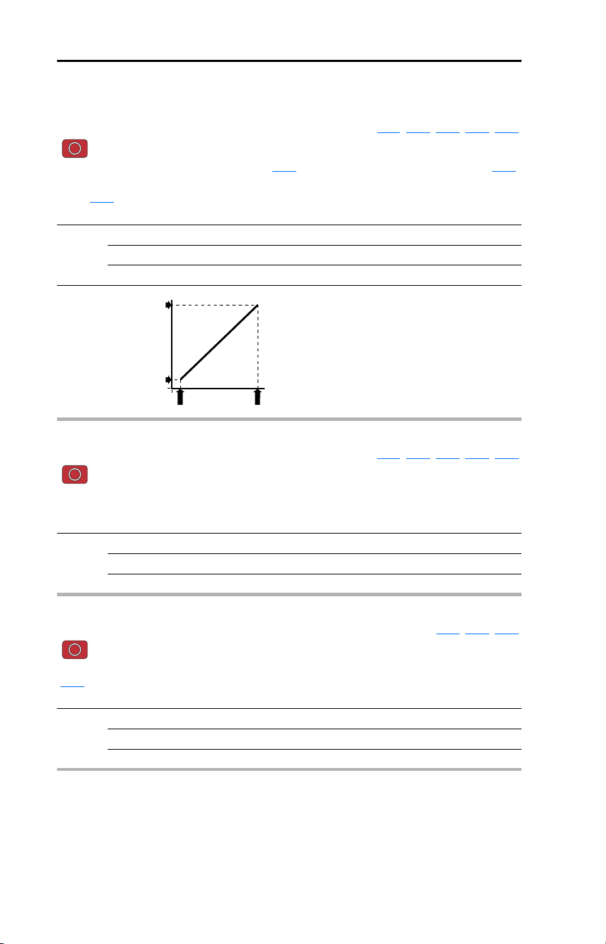
82 Rockwell Automation Publication 22D-UM001F-EN-E - September 2024
Chapter 3 Programming and Parameters
Advanced Program Group (continued)
A110 [Anlg In 0-10V Lo] Related Parameter(s): b020, P034, P038, A122, A123
Stop drive before changing this parameter.
Sets the analog input level that corresponds to P034
[Minimum Freq] if a 0-10V input is used by P038
[Speed Reference].
When A123
[10V Bipolar Enbl] is set to 1 “Bi-Polar In” this parameter is ignored.
Analog inversion can be accomplished by setting this value larger than A111 [Anlg In 0-10V Hi].
Values Default: 0.0%
Min/Max: 0.0/100.0%
Display: 0.1%
0
P035 [Maximum Freq]
P034 [Minimum Freq]
A110 [Anlg In 0-10V Lo] A111 [Anlg In 0-10V Hi]
0
Speed Reference
A111 [Anlg In 0-10V Hi] Related Parameter(s): b020, P035, P038, A122, A123
Stop drive before changing this parameter.
Sets the analog input level that corresponds to P035 [Maximum Freq] if a 0-10V input is used by P038
[Speed Reference].
Analog inversion can be accomplished by setting this value smaller than A110 [Anlg In 0-10V Lo].
Values Default: 100.0%
Min/Max: 0.0/100.0%
Display: 0.1%
A112 [Anlg In4-20mA Lo] Related Parameter(s): b021, P034, P038
Stop drive before changing this parameter.
Sets the analog input level that corresponds to P034 [Minimum Freq] if a 4-20mA input is used by
P038
[Speed Reference].
Analog inversion can be accomplished by setting this value larger than A113 [Anlg In4-20mA Hi].
Values Default: 0.0%
Min/Max: 0.0/100.0%
Display: 0.1%

Rockwell Automation Publication 22D-UM001F-EN-E - September 2024 83
Chapter 3 Programming and Parameters
Advanced Program Group (continued)
A113 [Anlg In4-20mA Hi] Related Parameter(s): b021, P035, P038
Stop drive before changing this parameter.
Sets the analog input level that corresponds to P035
[Maximum Freq] if a 4-20mA input is used by
P038
[Speed Reference].
Analog inversion can be accomplished by setting this value smaller than A112 [Anlg In4-20mA Lo].
Values Default: 100.0%
Min/Max: 0.0/100.0%
Display: 0.1%
A114 [Slip Hertz @ FLA] Related Parameter(s): P033, E216
Compensates for the inherent slip in an induction motor. This frequency is added to the commanded
output frequency.
Values Default: 2.0 Hz
Min/Max: 0.0/10.0 Hz
Display: 0.1 Hz
A115 [Process Time Lo] Related Parameter(s): b010, P034
Scales the time value when the drive is running at P034 [Minimum Freq]. When set to a value other
than zero, b010
[Process Display] indicates the duration of the process.
Values Default: 0.00
Min/Max: 0.00/99.99
Display: 0.01
A116 [Process Time Hi] Related Parameter(s): b010, P035
Scales the time value when the drive is running at P035 [Maximum Freq]. When set to a value other
than zero, b010
[Process Display] indicates the duration of the process.
Values Default: 0.00
Min/Max: 0.00/99.99
Display: 0.01
A117 [Bus Reg Mode]
Controls the operation of the drive voltage regulation, which is normally operational at decel or when
the bus voltage rises.
See the Attention statement on page 9
for important information on bus regulation.
Options 0 “Disabled”
1 “Enabled” (Default)
A118 [Current Limit 2] Related Parameter(s): P033, A051…A054, A089
Maximum output current allowed before current limiting occurs. This parameter is only active if
A051
…A054 [Digital Inx Sel] is set to 25 “Current Lmt2” and is active.
Values Default: Drive Rated Amps × 1.5
Min/Max: 0.1/(Drive Rated Amps × 1.8)
Display: 0.1 Amps
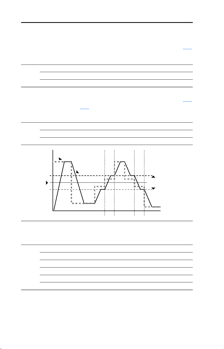
84 Rockwell Automation Publication 22D-UM001F-EN-E - September 2024
Chapter 3 Programming and Parameters
Advanced Program Group (continued)
A119 [Skip Frequency] Related Parameter(s): A120
Sets the frequency at which the drive will not operate.
A setting of 0 disables this parameter.
Values Default: 0 Hz
Min/Max: 0/500 Hz
Display: 1 Hz
A120 [Skip Freq Band] Related Parameter(s): A119
Determines the bandwidth around A119 [Skip Frequency]. A120 [Skip Frequency Band] is split
applying 1/2 above and 1/2 below the actual skip frequency.
A setting of 0.0 disables this parameter.
Values Default: 0.0 Hz
Min/Max: 0.0/30.0 Hz
Display: 0.1 Hz
Frequency
Time
Skip Frequency
Command
Frequency
Drive Output
Frequency
2x Skip
Frequency Band
A121 [Stall Fault Time]
Sets the time that the drive will remain in stall mode before a fault is issued.
Options 0 “60 Seconds” (Default)
1 “120 Seconds”
2 “240 Seconds”
3 “360 Seconds”
4 “480 Seconds”
5 “Flt Disabled”

Rockwell Automation Publication 22D-UM001F-EN-E - September 2024 85
Chapter 3 Programming and Parameters
Advanced Program Group (continued)
A122 [Analog In Loss] Related Parameter(s): A110, A111, A132
Selects drive action when an input signal loss is detected. Signal loss is defined as an analog signal
less than 1V or 2 mA. The signal loss event ends and normal operation resumes when the input signal
level is greater than or equal to 1.5V or 3 mA. If using a 0-10V analog input, set A110
[Anlg In 0-10V
Lo] to a minimum of 20% (that is 2 volts). Ensure that the Voltage Range Select DIP Switch is set to
10V.
Options 0 “Disabled” (Default)
1 “Fault (F29)” F29 Analog Input Loss
2 “Stop” Uses P037 [Stop Mode]
3 “Zero Ref” Drive runs at zero speed reference.
4 “Min Freq Ref” Drive runs at minimum frequency.
5 “Max Freq Ref” Drive runs at maximum frequency.
6 “Int Freq Ref” Drive runs at internal frequency.
A123 [10V Bipolar Enbl] Related Parameter(s): P038, A111
Enables/disables bipolar control. In bipolar mode direction is commanded by the sign of the reference.
Ensure that the Voltage Range Select DIP Switch setting matches the selected control scheme.
See Figure 5
.
Options 0 “Uni-Polar In” (Default) 0 to 10V only
1 “Bi-Polar In” ±10V
A124 [Var PWM Disable] Related Parameter(s): A091
Stop drive before changing this parameter.
Enables/disables a feature that varies the carrier frequency for the PWM output waveform defined by
A091
[PWM Frequency].
Disabling this feature when low frequency conditions exist may result in IGBT stress and nuisance
tripping.
Options 0 “Enabled” (Default)
1 “Disabled”
A125 [Torque Perf Mode] Related Parameter(s): A084, A085, A086, A087, A127
Stop drive before changing this parameter.
Enables/disables sensorless vector control operation.
Options 0 “V/Hz”
1 “Sensrls Vect” (Default)

86 Rockwell Automation Publication 22D-UM001F-EN-E - September 2024
Chapter 3 Programming and Parameters
Advanced Program Group (continued)
A126 [Motor NP FLA] Related Parameter(s): A127
Set to the motor nameplate rated full load amps.
Values Default: Drive Rated Amps
Min/Max: 0.1/(Drive Rated Amps × 2)
Display: 0.1 Amps
A127 [Autotune] Related Parameter(s): A125, A126, A128, A129
Stop drive before changing this parameter.
Provides an automatic method for setting A128 [IR Voltage Drop] and A129 [Flux Current Ref], which
affect sensorless vector performance. Parameter A126
[Motor NP FLA] must be set to the motor
nameplate full load amps before running the Autotune procedure.
Options 0 “Ready/Idle” (Default)
1 “Static Tune”
2 “Rotate Tune”
“Ready” (0) = Parameter returns to this setting following a “Static Tune” or “Rotate Tune.”
“Static Tune” (1) = A temporary command that initiates a non-rotational motor stator resistance test for
the best possible automatic setting of A128 [IR Voltage Drop]. A start command is required following
initiation of this setting. The parameter returns to “Ready” (0) following the test, at which time another
start transition is required operate the drive in normal mode. Used when motor cannot be uncoupled
from the load.
“Rotate Tune” (2) = A temporary command that initiates a “Static Tune” followed by a rotational test for
the best possible automatic setting of A129 [Flux Current Ref]. A start command is required following
initiation of this setting. The parameter returns to “Ready/Idle” (0) following the test, at which time
another start transition is required to operate the drive in normal mode.
Important: Used when motor is uncoupled from the load. Results may not be valid if a load is coupled
to the motor during this procedure.
If the Autotune routine fails, an F80
SVC Autotune fault is displayed.
!
ATTENTION: Rotation of the motor in an undesired direction can occur during this
procedure. To guard against possible injury and/or equipment damage, it is
recommended that the motor be disconnected from the load before proceeding.
A128 [IR Voltage Drop] Related Parameter(s): A127
Value of volts dropped across the resistance of the motor stator.
Values Default: Based on Drive Rating
Min/Max: 0.0/230.0 VAC
Display: 0.1 VAC

Rockwell Automation Publication 22D-UM001F-EN-E - September 2024 87
Chapter 3 Programming and Parameters
Advanced Program Group (continued)
A129 [Flux Current Ref] Related Parameter(s): A127
Value of amps for full motor flux.
Values Default: Based on Drive Rating
Min/Max: 0.00/[Motor NP FLA]
Display: 0.01 Amps
A130 [PID Trim Hi]
Sets the maximum positive value that is added to a PID reference when PID trim is used.
Values Default: 60.0 Hz
Min/Max: 0.0/500.0 Hz
Display: 0.1 Hz
A131 [PID Trim Lo]
Sets the minimum positive value that is added to a PID reference when PID trim is used.
Values Default: 0.0 Hz
Min/Max: 0.0/500.0 Hz
Display: 0.1 Hz
A132 [PID Ref Sel] Related Parameter(s): P038, A122
Stop drive before changing this parameter.
Enables/disables PID mode and selects the source of the PID reference. See Appendix
F for details.
Options 0 “PID Disabled”
(Default)
1 “PID Setpoint”
2 “0-10V Input”
3 “4-20mA Input”
4 “Comm Port”
5 “Encoder” Encoder or Pulse Train
6 “Setpnt, Trim”
7 “0-10V, Trim”
8 “4-20mA, Trim”
9 “Comm, Trim”
10 “Encoder,Trim” Encoder or Pulse Train

88 Rockwell Automation Publication 22D-UM001F-EN-E - September 2024
Chapter 3 Programming and Parameters
Advanced Program Group (continued)
A133 [PID Feedback Sel]
Select the source of the PID feedback. See Appendix F for details.
Options 0 “0-10V Input” (Default) The PID will not function with a bipolar input. Negative
voltages are treated as 0 volts.
1 “4-20mA Input”
2 “Comm Port”
3 “Encoder” Encoder or Pulse Train
A134 [PID Prop Gain]
Sets the value for the PID proportional component when the PID mode is enabled by A132 [PID Ref
Sel].
Values Default: 0.01
Min/Max: 0.00/99.99
Display: 0.01
!
ATTENTION: The loss of analog input, encoder or other feedback may cause
unintended speed or motion. Take appropriate precautions to guard against possible
unintended speed or motion.
A135 [PID Integ Time]
Sets the value for the PID integral component when the PID mode is enabled by A132 [PID Ref Sel].
Values Default: 2.0 Secs
Min/Max: 0.0/999.9 Secs
Display: 0.1 Secs
A136 [PID Diff Rate]
Sets the value for the PID differential component when the PID mode is enabled by A132 [PID Ref
Sel].
Values Default: 0.00 (1/Secs)
Min/Max: 0.00/99.99 (1/Secs)
Display: 0.01 (1/Secs)

Rockwell Automation Publication 22D-UM001F-EN-E - September 2024 89
Chapter 3 Programming and Parameters
Advanced Program Group (continued)
A137 [PID Setpoint]
Provides an internal fixed value for process setpoint when the PID mode is enabled by A132 [PID Ref
Sel].
Values Default: 0.0%
Min/Max: 0.0/100.0%
Display: 0.1%
A138 [PID Deadband]
Sets the lower limit of the PID output.
Values Default: 0.0%
Min/Max: 0.0/10.0%
Display: 0.1%
A139 [PID Preload]
Sets the value used to preload the integral component on start or enable.
Values Default: 0.0 Hz
Min/Max: 0.0/500.0 Hz
Display: 0.1 Hz

90 Rockwell Automation Publication 22D-UM001F-EN-E - September 2024
Chapter 3 Programming and Parameters
Advanced Program Group (continued)
A140 [Stp Logic 0]
A141 [Stp Logic 1]
A142 [Stp Logic 2]
A143 [Stp Logic 3]
A144 [Stp Logic 4]
A145 [Stp Logic 5]
A146 [Stp Logic 6]
A147 [Stp Logic 7]
Related Parameter(s): P038, P039, P040, A051…A054,
A055
, A058, A061, A067, A068, A070…A077,
A150
…A157, E248
Values Default: 00F1
Min/Max: 0001/FAFF
Display: 4 Digits
For detailed information on applying StepLogic and Position StepLogic, see Appendix
E and Appendix
F.
Parameters A140…A147 are only active if P038
[Speed Reference] is set to 6 “Stp Logic” or 9
“Positioning”.
These parameters can be used to create a custom profile of frequency commands. Each “step” can
be based on time, status of a Logic input or a combination of time and the status of a Logic input.
Digits 0…3 for each [Stp Logic x] parameter must be programmed according to the desired profile.
A Logic input is established by setting a digital input, parameters A051
…A054 [Digital Inx Sel], to 23
“Logic In1” and/or 24 “Logic In2” or by using Bits 6 and 7 of E248
[Enh Control Word].
A time interval between steps can be programmed using parameters A150
…A157 [Stp Logic Time x].
See the table below for related parameters.
The speed for any step is programmed using parameters A070
…A077 [Preset Freq x].
The position for any step is programmed using parameters E230
…E245 [Step Units x].
Stop drive before changing this parameter.
Step StepLogic Parameter
Related Preset Frequency Parameter
(Can be activated independent of
StepLogic Parameters)
Related StepLogic Time Parameter
(Active when A140-A147 Digit 0 or 1
are set to 1, b, C, d or E)
0 A140 [Stp Logic 0] A070 [Preset Freq 0] A150 [Stp Logic Time 0]
1 A141 [Stp Logic 1] A071 [Preset Freq 1] A151 [Stp Logic Time 1]
2 A142 [Stp Logic 2] A072 [Preset Freq 2] A152 [Stp Logic Time 2]
3 A143 [Stp Logic 3] A073 [Preset Freq 3] A153 [Stp Logic Time 3]
4 A144 [Stp Logic 4] A074 [Preset Freq 4] A154 [Stp Logic Time 4]
5 A145 [Stp Logic 5] A075 [Preset Freq 5] A155 [Stp Logic Time 5]
6 A146 [Stp Logic 6] A076 [Preset Freq 6] A156 [Stp Logic Time 6]
7 A147 [Stp Logic 7] A077 [Preset Freq 7] A157 [Stp Logic Time 7]
Step StepLogic Position Parameters
0 E230 [Step Units 0] & E231 [Step Units F 0]
1 E232 [Step Units 1] & E233 [Step Units F 1]
2 E234 [Step Units 2] & E235 [Step Units F 2]
3 E236 [Step Units 3] & E237 [Step Units F 3]
4 E238 [Step Units 4] & E239 [Step Units F 4]
5 E240 [Step Units 5] & E241 [Step Units F 5]
6 E242 [Step Units 6] & E243 [Step Units F 6]
7 E244 [Step Units 7] & E245 [Step Units F 7]

Rockwell Automation Publication 22D-UM001F-EN-E - September 2024 91
Chapter 3 Programming and Parameters
How StepLogic Works
The StepLogic sequence begins with a valid start command. A normal sequence always begins with
A140 [Stp Logic 0].
Digit 0: Logic For Next Step
This digit defines the logic for the next step. When the condition is met the program advances to the
next step. Step 0 follows Step 7. Example: Digit 0 is set 3. When “Logic In2” becomes active, the
program advances to the next step.
Digit 1: Logic to Jump to a Different Step
For all settings other than F, when the condition is met, the program overrides Digit 0 and jumps to the
step defined by Digit 2.
Digit 2: Different Step to Jump
When the condition for Digit 1 is met, the Digit 2 setting determines the next step or to end the
program.
Digit 3: Step Settings
This digit defines additional characteristics of each step.
Any StepLogic parameter can be programmed to control a relay or opto output, but you can not
control different outputs based on the condition of different StepLogic commands.
!
ATTENTION: If the StepLogic sequence continues running and never stops while
Parameter E222 [Positioning Mode] is set to 2, 3, or 4, remove power to the drive and
swap the A and A (NOT) encoder channels.

92 Rockwell Automation Publication 22D-UM001F-EN-E - September 2024
Chapter 3 Programming and Parameters
StepLogic Settings
The logic for each function is determined by the four digits for each StepLogic parameter. The
following is a listing of the available settings for each digit.
See Appendix
E for details.
Logic For Next Step Digit 0
Logic to Jump to a Different Step Digit 1
Different Step to Jump Digit 2
Step Settings Digit 3
Velocity Control Settings (Digit 3)
Required
Setting
Accel/Decel
Param. Used
StepLogic
Output State
Commanded
Direction
0
1
2
3
4
5
6
7
8
9
A
b
Accel/Decel 1
Accel/Decel 1
Accel/Decel 1
Accel/Decel 1
Accel/Decel 1
Accel/Decel 1
Accel/Decel 2
Accel/Decel 2
Accel/Decel 2
Accel/Decel 2
Accel/Decel 2
Accel/Decel 2
Off
Off
Off
On
On
On
Off
Off
Off
On
On
On
FWD
REV
No Output
FWD
REV
No Output
FWD
REV
No Output
FWD
REV
No Output
Positioning Settings (Digit 3)
Required
Setting
Accel/Decel
Param. Used
StepLogic
Output State
Direction
From Home
Type Of
Command
0
1
2
3
4
5
6
7
8
9
A
b
C
d
E
F
Accel/Decel 1
Accel/Decel 1
Accel/Decel 1
Accel/Decel 1
Accel/Decel 1
Accel/Decel 1
Accel/Decel 1
Accel/Decel 1
Accel/Decel 2
Accel/Decel 2
Accel/Decel 2
Accel/Decel 2
Accel/Decel 2
Accel/Decel 2
Accel/Decel 2
Accel/Decel 2
Off
Off
Off
Off
On
On
On
On
Off
Off
Off
Off
On
On
On
On
FWD
FWD
REV
REV
FWD
FWD
REV
REV
FWD
FWD
REV
REV
FWD
FWD
REV
REV
Absolute
Incremental
Absolute
Incremental
Absolute
Incremental
Absolute
Incremental
Absolute
Incremental
Absolute
Incremental
Absolute
Incremental
Absolute
Incremental
Settings (Digit 2) Settings (Digit 1 and Digit 0)
0 = Jump to Step 0
1 = Jump to Step 1
2 = Jump to Step 2
3 = Jump to Step 3
4 = Jump to Step 4
5 = Jump to Step 5
6 = Jump to Step 6
7 = Jump to Step 7
8 = End Program (Normal Stop)
9 = End Program (Coast-to-Stop)
A = End Program and Fault (F2)
0 = Skip Step (Jump Immediately)
1 = Step Based on [Stp Logic Time x]
2 = Step if “Logic In1” is Active
3 = Step if “Logic In2” is Active
4 = Step if “Logic In1” is Not Active
5 = Step if “Logic In2” is Not Active
6 = Step if either “Logic In1” or “Logic In2” is Active
7 = Step if both “Logic In1” and “Logic In2” is Active
8 = Step if neither “Logic In1” or “Logic In2” is Active
9 = Step if “Logic In1” is Active and “Logic In2” is Not Active
A = Step if “Logic In2” is Active and “Logic In1” is Not Active
b = Step after [Stp Logic Time x] and “Logic In1” is Active
C = Step after [Stp Logic Time x] and “Logic In2” is Active
d = Step after [Stp Logic Time x] and “Logic In1” is Not Active
E = Step after [Stp Logic Time x] and “Logic In2” is Not Active
F = Do Not Step/Ignore Digit 2 Settings
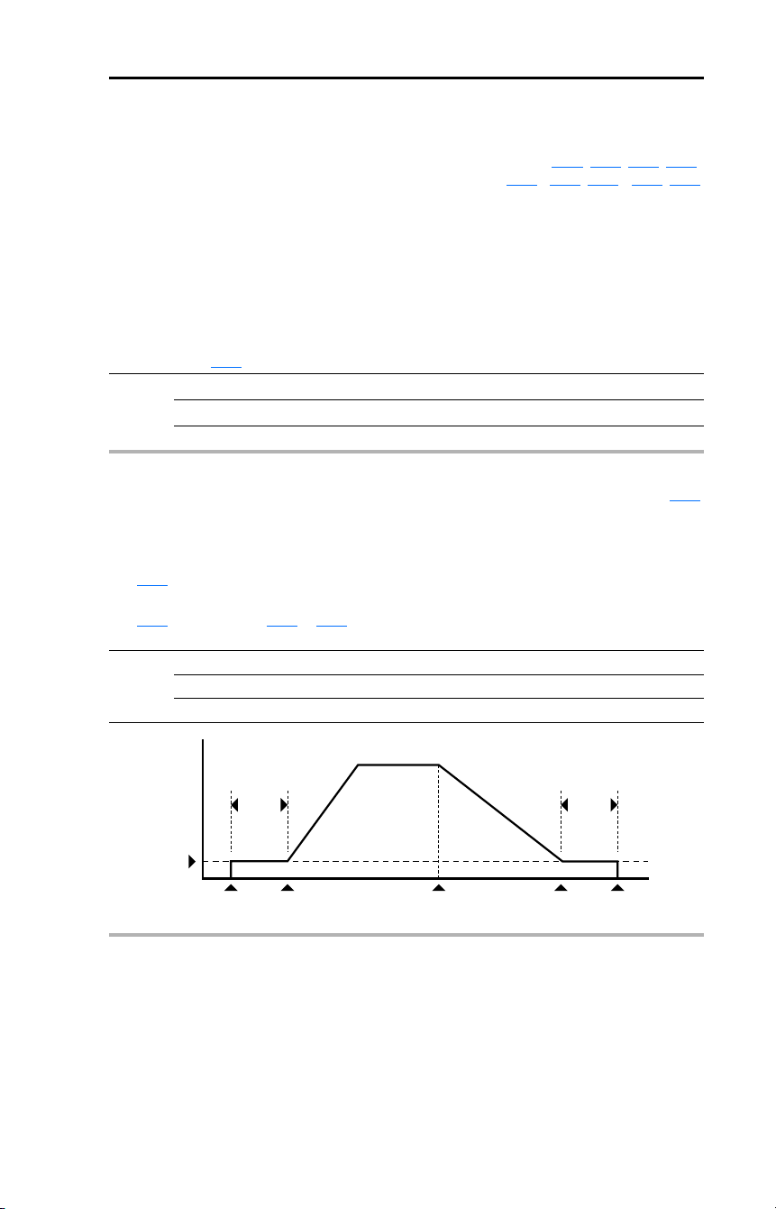
Rockwell Automation Publication 22D-UM001F-EN-E - September 2024 93
Chapter 3 Programming and Parameters
Advanced Program Group (continued)
A150 [Stp Logic Time 0]
A151 [Stp Logic Time 1]
A152 [Stp Logic Time 2]
A153 [Stp Logic Time 3]
A154 [Stp Logic Time 4]
A155 [Stp Logic Time 5]
A156 [Stp Logic Time 6]
A157 [Stp Logic Time 7]
Related Parameter(s): P038, A055, A058, A061,
A070
…A077, A140…A147, E222
Sets the time to remain in each step if the corresponding StpLogic command word is set to “Step after
Time” or if using E222
[Positioning Mode] set to 0.
Values Default: 30.0 Secs
Min/Max: 0.0/6553.5 Secs
Display: 0.1 Secs
A160 [EM Brk Off Delay] Related Parameter(s): P037
Sets the time the drive remains at minimum frequency before the relay or an opto output is energized
and the drive ramps to the commanded frequency.
The relay or opto output is typically connected to a user-supplied electromechanical brake coil relay.
Set P037
[Stop Mode] to 8 “Ramp+EM B,CF” or 9 “Ramp+EM Brk” to enable the electromechanical
brake option.
Set A055
[Relay Out Sel], A058 or A061 [Opto Outx Sel] to 22 “EM Brk Cntrl” to control brake
operation.
Values Default: 2.00 Secs
Min/Max: 0.01/10.00 Secs
Display: 0.01 Secs
Frequency
Time
Minimum Freq
A160 [EM Brk Off Delay]
A161 [EM Brk On Delay]
Stop
Commanded
Start
Commanded
EM Brk
De-Energized (On)
Drive StopsEM Brk
Energized (Off)
Ramp Accel
Ramp Decel

94 Rockwell Automation Publication 22D-UM001F-EN-E - September 2024
Chapter 3 Programming and Parameters
Advanced Program Group (continued)
A161 [EM Brk On Delay] Related Parameter(s): P037
Sets the time the drive remains at minimum frequency before the relay or an opto output is
de-energizing and the drive stops.
The relay or opto output is typically connected to a user-supplied electromechanical brake coil relay.
Set P037
[Stop Mode] to 8 “Ramp+EM B,CF” or 9 “Ramp+EM Brk” to enable the electromechanical
brake option.
Set A055
[Relay Out Sel], A058 or A061 [Opto Outx Sel] to 22 “EM Brk Cntrl” to control brake
operation.
Values Default: 2.00 Secs
Min/Max: 0.01/10.00 Secs
Display: 0.01 Secs
A162 [MOP Reset Sel] Related Parameter(s): A069
Set the drive to save the current MOP reference command.
Options 0 “Zero MOP Ref” This option clamps A069
[Internal Freq] at 0.0 Hz when the
drive is not running.
1 “Save MOP Ref”
(Default)
Reference is saved in A069
[Internal Freq].
A163 [DB Threshold] Related Parameter(s): P037, A080, A081, A082
Sets the DC bus Voltage Threshold for Dynamic Brake operation. If the DC bus voltage falls below the
value set in this parameter, the Dynamic Brake will not turn on. Lower values will make the Dynamic
Braking function more responsive but may result in nuisance Dynamic Brake activation.
Values Default 100.0%
Min/Max: 0.0/110.0%
Display: 0.0%
!
ATTENTION: Equipment damage may result if this parameter is set a value
that causes the dynamic braking resistor to dissipate excessive power.
Parameter settings less than 100% should be carefully evaluated to ensure
that the dynamic brake resistor’s wattage rating is not exceeded. In general,
values less than 90% are not needed. This parameter’s setting is especially
important if parameter A082 [DB Resistor Sel] is set to 2 “No Protection”.
A164 [PID Invert Error]
When set to “Inverted”, changes the sign of the PID error. This causes an increase in the drive output
frequency with PID Feedback greater than PID Setpoint, and a decrease in drive output frequency
with PID Feedback less than PID Setpoint.
Options 0 “Not Inverted” (Default)
1 “Inverted

Rockwell Automation Publication 22D-UM001F-EN-E - September 2024 95
Chapter 3 Programming and Parameters
Enhanced Program Group
E201 [LED Display Opt]
Selects which parameters can be viewed by the drive’s LED interface.
Values Default: 2
Min/Max: 0/3
Display: 1
E201 Option Parameter Set
0
1
2
3
All Basic Display (Group b) and Advanced Display (Group d) parameters
All Basic Display Group (b001-b029) parameters
Basic Display Group parameters b001-b007 and b010
Basic Display Group parameter b001-b004
E202 [Digital Term 3]
Stop drive before changing this parameter.
Sets the function of I/O Terminal 03.
Options 0 “Start Source” (Default) Input functions as defined by P036
[Start Source].
1 “Acc/Dec Sel1” If active, can determine which Accel/Decel time will be used
for all ramp rates except jog. Can be applied to one input only.
See A067
[Accel Time 2] for details.
2 “Jog” • When input is present, drive accelerates according to the
value set in A079
[Jog Accel/Decel] and ramps to the
value set in A078
[Jog Frequency].
• When input is removed, drive ramps to a stop according to
the value set in A079
[Jog Accel/Decel].
• A valid “Start” command will override this input.
3 “Aux Fault” When enabled, an F2 Auxiliary Input
fault will occur when the
input is removed.
4 “Preset Freq” See A070
…A077 [Preset Freq x].
Important: Digital Inputs have priority for frequency control
when programmed as Preset Speed and are active. See the
flowchart on page 38
for more information on speed
reference control priority.
5 “Reserved”
6 “Comm Port” • When active, sets communications device as default start/
speed command source.
• Can only be tied to one input.
7 “Clear Fault” When active, clears an active fault.
8 “RampStop,CF” Causes drive to immediately ramp to a stop regardless of how
P037
[Stop Mode] is set.
9 “CoastStop,CF” Causes drive to immediately coast to a stop regardless of
how P037
[Stop Mode] is set.
10 “DCInjStop,CF” Causes drive to immediately begin a DC Injection stop
regardless of how P037
[Stop Mode] is set.

96 Rockwell Automation Publication 22D-UM001F-EN-E - September 2024
Chapter 3 Programming and Parameters
E202
Options
(Cont.)
11 “Jog Forward” Drive accelerates to A078 [Jog Frequency] according to A079
[Jog Accel/Decel] and ramps to stop when input becomes
inactive. A valid start will override this command.
12 “Jog Reverse” Drive accelerates to A078
[Jog Frequency] according to A079
[Jog Accel/Decel] and ramps to stop when input becomes
inactive. A valid start will override this command.
13 “10V In Ctrl” Selects 0-10V or ±10V control as the frequency reference.
Start source is not changed.
14 “20mA In Ctrl” Selects 4-20mA control as the frequency reference. Start
source is not changed.
15 “PID Disable” Disables PID function. Drive uses the next valid non-PID
speed reference.
16 “MOP Up” Increases the value of A069
[Internal Freq] at a rate of 2 Hz
per second. Default for A069 is 60 Hz.
17 “MOP Down” Decreases the value of A069
[Internal Freq] at a rate of 2 Hz
per second. Default for A069 is 60 Hz.
18 “Timer Start” Clears and starts the timer function. May be used to control
the relay or opto outputs.
19 “Counter In” Starts the counter function. May be used to control the relay
or opto outputs.
20 “Reset Timer” Clears the active timer.
21 “Reset Countr” Clears the active counter.
22 “Rset Tim&Cnt” Clears the active timer and counter.
23 “Logic In1” Logic function input number 1. May be used to control the
relay or opto outputs (see parameters A055
, A058, A061
Options 11…14). May be used in conjunction with StepLogic
parameters A140
…A147 [Stp Logic x]. Logically ORed with
E248
[Enh Control Word] bit 6 “Logic In 1”.
24 “Logic In2” Logic function input number 2. May be used to control the
relay or opto outputs (see parameters A055
, A058, A061
Options 11-14). May be used in conjunction with StepLogic
parameters A140
…A147 [Stp Logic x]. Logically ORed with
E248
[Enh Control Word] bit 7 “Logic In 2”.
25 “Current Lmt2” When active, A118
[Current Limit 2] determines the drive
current limit level.
26 “Anlg Invert” Inverts the scaling of the analog input levels set in
A110
[Anlg In 0-10V Lo] and A111 [Anlg In 0-10V Hi] or
A112
[Anlg In4-20mA Lo] and A113 [Anlg In4-20mA Hi].
27 “EM Brk Rlse” If EM brake function is enabled, this input releases the brake.
See A160
[EM Brk Off Delay] for additional information.
!
ATTENTION: If a hazard of injury due to movement of equipment or
material exists, an auxiliary mechanical braking device must be used.

Rockwell Automation Publication 22D-UM001F-EN-E - September 2024 97
Chapter 3 Programming and Parameters
E202
Options
(Cont.)
28 “Acc/Dec Sel2” If active, can determine which
Accel/Decel time will be used for
all ramp rates except jog. Can
be applied to one input only.
29 “Precharge En” Forces drive into precharge state. Typically controlled by
auxiliary contact on the disconnect at the DC input to the
drive. If this input is assigned, it must be energized for the
pre-charge relay to close and for the drive to run. If it is
de-energized, the pre-charge relay will open and the drive will
coast to a stop.
30 “Inertia Dcel” Forces drive into Inertia Ride-through state. The drive will
attempt to regulate the DC bus at the current level.
31 “Sync Enable” Must be used in order to hold the existing frequency when
Sync Time is set to enable speed synchronization. When this
input is released the drive will accelerate to the commanded
frequency in E214
[Sync Time].
32 “Traverse Dis” When an input is programmed the traverse function will be
disabled while this input is active. See E210
[Max Traverse]
33 “Home Limit” In Positioning mode, this indicates the drive is at the home
position. See Appendix
F for detailed information on
positioning.
34 “Find Home” In Positioning mode this causes the drive to return to the
Home position when a start is issued. It does this by using the
[Find Home Freq] and [Find Home Direction] until the “Home
Limit” input is activated. If it passes this point, it then runs in
the reverse direction at 1/10th the frequency of [Find Home
Freq] until the “Home Limit” is activated again. As long as this
input is active, any start command will cause the drive to
enter the homing routing. However, it only functions if in
Positioning mode. Once the Find Home routine has finished,
the drive will stop. See Appendix
F for detailed information on
positioning.
35 “Hold Step” In Positioning mode, this input over-rides other inputs and
causes the drive to remain at it’s current step (running at zero
speed once it reaches its position) until released. While in
“Hold”, the drive will ignore any digital input command which
would normally result in a move to a new step. However,
timers continue to run. Therefore, when the Hold is removed,
the drive must see any required digital inputs transition (even
if they already transitioned during the hold), but it does not
reset any timer. See Appendix
F for detailed information on
positioning.
36 “Pos Redefine” In Positioning mode, this input resets the home position to the
current position of the machine. See Appendix
F for detailed
information on positioning.
Option
Description28 1
00Acc/Dec 1
01Acc/Dec 2
10Acc/Dec 3
11Acc/Dec 4

98 Rockwell Automation Publication 22D-UM001F-EN-E - September 2024
Chapter 3 Programming and Parameters
Enhanced Program Group (continued)
E203 [Accel Time 3] Related Parameter(s): A067
E205 [Accel Time 4]
Sets the rate of acceleration for all speed increases when selected by digital inputs. See the graphic at
A067
[Accel Time 2].
Values Default: 5.0 Secs (E203)
30.0 Secs (E205)
Min/Max: 0.0/600.0 Secs
Display: 0.1 Secs
Maximum Freq
Accel Time
Accel Rate
=
E204 [Decel Time 3] Related Parameter(s): A067
E206 [Decel Time 4]
Sets the rate of deceleration for all speed decreases when selected by digital inputs. See the graphic
at A067
[Accel Time 2].
Values Default: 5.0 Secs (E204)
30.0 Secs (E206)
Min/Max: 0.0/600.0 Secs
Display: 0.1 Secs
Maximum Freq
Decel Time
Decel Rate
=
E207 [Comm Write Mode]
Saves parameter values in active drive memory (RAM) or in drive non-volatile memory (EEPROM).
Important: Parameter values set prior to selecting option 1 “RAM only” will be saved in drive
non-volatile memory (EEPROM).
Options 0 “EEPROM” (Default)
1 “RAM only”
E208 [Power Loss Mode]
Sets the reaction to a loss of input power.
Options 0 “Coast” (Default) Drive will fault and motor will coast-to-stop.
1 “Decel” Drive will decelerate and attempt to keep the DC Bus voltage
above the undervoltage level.
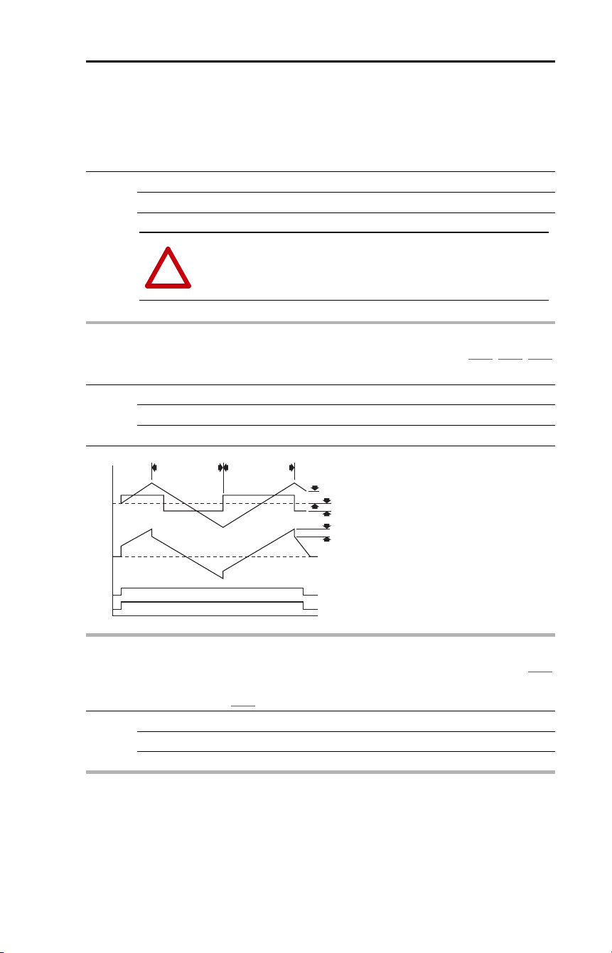
Rockwell Automation Publication 22D-UM001F-EN-E - September 2024 99
Chapter 3 Programming and Parameters
Enhanced Program Group (continued)
E209 [Half Bus Enable]
Enables/disables the power ride through function which allows the drive to maintain power to the
motor at 50% drive input voltage during short-term power sag conditions.
Options 0 “Disabled” (Default)
1 “Enabled”
!
ATTENTION: To guard against drive damage, a minimum line impedance
must be provided to limit inrush current when the power line recovers. The
input impedance should be equal or greater than the equivalent of a 5%
transformer with a VA rating 6 times the drive’s input VA rating.
E210 [Max Traverse] Related Parameter(s): E211, E212, E213
Sets the amplitude of triangle wave speed modulation.
Values Default: 0.00 Hz (Disabled)
Min/Max: 0.00/300.0 Hz
Display: 0.01 Hz
Hertz
Seconds
Traverse Bit
212 [Traverse Dec] 211 [Traverse Inc]
Traverse Enable Bit
d302 [Fiber Status]
b001 [Output Freq]
E213 [P Jump]
E210 [Max Traverse]
E213 [P Jump]
E211 [Traverse Inc] Related Parameter(s): E210
Sets time required for the Traverse function to accelerate from the minimum to the maximum traverse
frequency. See the diagram at E210
[Max Traverse].
Values Default: 0.00 Secs
Min/Max: 0.00/30.00 Secs
Display: 0.01 Secs
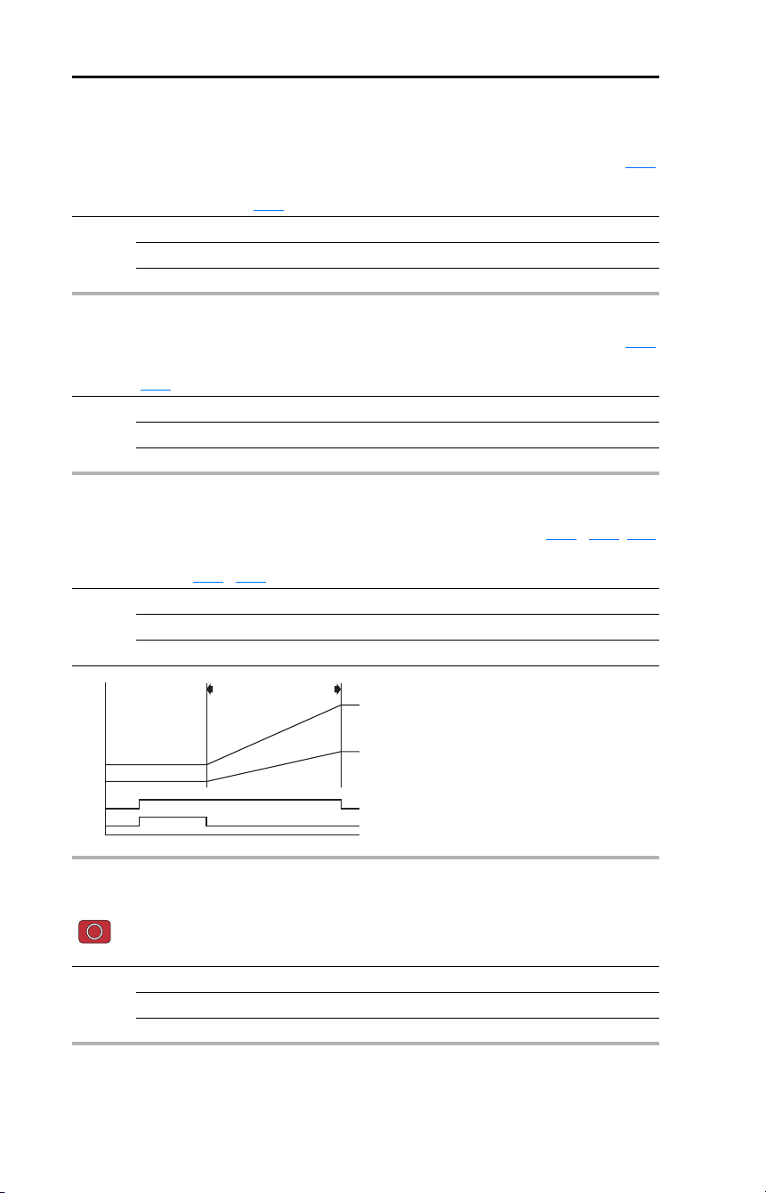
100 Rockwell Automation Publication 22D-UM001F-EN-E - September 2024
Chapter 3 Programming and Parameters
Enhanced Program Group (continued)
E212 [Traverse Dec] Related Parameter(s): E210
Sets time required for the Traverse function to decelerate from the maximum to the minimum traverse
frequency. See the diagram at E210
[Max Traverse].
Values Default: 0.00 Secs
Min/Max: 0.00/30.00 Secs
Display: 0.01 Secs
E213 [P Jump] Related Parameter(s): E210
Sets the frequency amplitude that is added to or subtracted from the commanded frequency. See the
diagram at E210
[Max Traverse].
Values Default: 0.00 Hz
Min/Max: 0.00/300.0 Hz
Display: 0.01 Hz
E214 [Sync Time] Related Parameter(s): A051…A054, d302
Enables the function that holds the drive at the current frequency even if the commanded frequency
changes. Used with A051
…A054 [Digital Inx Sel] option 31 “Sync Enable”.
Values Default: 0.0 Secs (Disabled)
Min/Max: 0.0/3200.0 Secs
Display: 0.1 Secs
Hertz
Time
Speed Sync Bit
Change Ref's
214 [Sync Time]
Drive #1 and #2 Sync Enable Input
d302 [Fiber Status]
New Drive #1 Reference
New Drive #2 Reference
E215 [Speed Ratio]
Stop drive before changing this parameter.
Enables the function that scales the drive speed command.
Values Default: 1.00
Min/Max: 0.01/99.99
Display: 0.01
Rockwell Automation Publication 22D-UM001F-EN-E - September 2024 101
Chapter 3 Programming and Parameters
Enhanced Program Group (continued)
E216 [Motor Fdbk Type]
Stop drive before changing this parameter.
Selects the encoder type. For additional information, see Appendix
F.
Values Default: 0
Min/Max: 0/5
Display: 1
E216 Option Encoder
0
1
2
3
4
5
None
Pulse Train
Single Chan
Single Check
Quadrature
Quad Check
!
ATTENTION: The loss of analog input, encoder or other feedback may cause
unintended speed or motion. Take appropriate precautions to guard against possible
unintended speed or motion.
E217 [Motor NP Poles]
Defines the number of poles in the motor.
Values Default: 4
Min/Max: 2/40
Display: 1
E218 [Encoder PPR]
Specifies the encoder pulses per revolution when an encoder is used. For additional information, see
Appendix
F.
Values Default: 1024
Min/Max: 1/20000
Display: 1
E219 [Pulse In Scale]
Sets the scale factor/gain for the Pulse Input when E216 [Motor Fdbk Type] is set to 1 “Pulse Train”.
For additional information, see Appendix
F.
Values Default: 64
Min/Max: 1/20000
Display: 1
Input Pulse Rate
Desired Command
Speed Command
=

102 Rockwell Automation Publication 22D-UM001F-EN-E - September 2024
Chapter 3 Programming and Parameters
Enhanced Program Group (continued)
E220 [Ki Speed Loop]
Sets the I-gain used in the PI calculation of the speed loop.
Values Default: 2.0
Min/Max: 0.0/400.0
Display: 0.1
E221 [Kp Speed Loop]
Sets the P-gain used in the PI calculation of the speed loop.
Values Default: 0.5
Min/Max: 0.0/200.0
Display: 0.1
E222 [Positioning Mode]
Stop drive before changing this parameter.
Defines the positioning transition mode used for the position steps. For additional information, see
Appendix
F.
Values Default: 0
Min/Max: 0/4
Display: 1
E222 Option Transition Mode Description
0
1
2
3
4
Time Steps
Preset Input
Step Logic
Preset StpL
StpLogic-Lst
Steps based on time.
Preset inputs directly command a given step.
Use Step Logic commands. Always start from Step 0.
Use Preset inputs to determine starting step then Step Logic commands.
Use Step Logic commands from last StepLogic step at last drive stop.
E223 [Find Home Freq]
Sets the maximum frequency the drive uses when “Find Home” is issued. For additional information,
see Appendix
F.
Values Default: 10.0 Hz
Min/Max: 0.1/500.0 Hz
Display: 0.1 Hz

Rockwell Automation Publication 22D-UM001F-EN-E - September 2024 103
Chapter 3 Programming and Parameters
Enhanced Program Group (continued)
E224 [Find Home Dir]
Stop drive before changing this parameter.
Sets the direction the drive commands when “Find Home” is issued. For additional information, see
Appendix
F.
Options 0 “Forward” (Default)
1 “Reverse”
E225 [Encoder Pos Tol]
Sets the “At Position” and the “At Home” tolerance around the encoder count. The value is added to
and subtracted from the target encoder unit value to create the tolerance range. For additional
information, see Appendix
F.
Values Default: 100
Min/Max: 1/50000
Display: 1
E226 [Counts Per Unit] Related Parameter(s): E230…E245
Sets the number of encoder counts equal to one user-defined unit. For additional information, see
Appendix
F.
Values Default: 4096
Min/Max: 1/32000
Display: 1
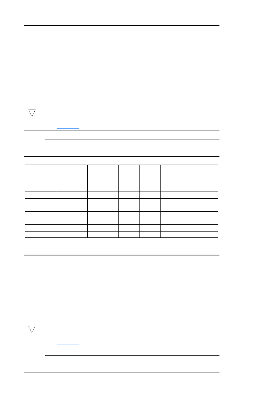
104 Rockwell Automation Publication 22D-UM001F-EN-E - September 2024
Chapter 3 Programming and Parameters
Enhanced Program Group (continued)
E230 [Step Units 0]
E232 [Step Units 1]
E234 [Step Units 2]
E236 [Step Units 3]
E238 [Step Units 4]
E240 [Step Units 5]
E242 [Step Units 6]
E244 [Step Units 7]
32-bit parameter.
Related Parameter(s): E226
Sets the position in whole number user-defined units the drive must reach at each step. For additional
information, see Appendix
F.
Values Default: 0
Min/Max: 0/64000
Display: 1
32
Input State
of Digital In 1
(I/O Terminal 05
when A051 = 4)
Input State
of Digital In 2
(I/O Terminal 06
when A052 = 4)
Input State
of Digital In 3
(I/O Terminal 07
when A053 = 4)
Position
Source
Freq
Source Accel / Decel Parameter Used
(2)
0 0 0 E230 A070 [Accel Time 1] / [Decel Time 1]
1 0 0 E232 A071 [Accel Time 1] / [Decel Time 1]
0 1 0 E234 A072 [Accel Time 2] / [Decel Time 2]
1 1 0 E236 A073 [Accel Time 2] / [Decel Time 2]
0 0 1 E238 A074 [Accel Time 1] / [Decel Time 1]
1 0 1 E240 A075 [Accel Time 1] / [Decel Time 1]
0 1 1 E242 A076 [Accel Time 2] / [Decel Time 2]
1 1 1 E244 A077 [Accel Time 2] / [Decel Time 2]
(2)
When a Digital Input is set to “Accel 2 & Decel 2”, and the input is active, that input overrides the settings in this
table.
E231 [Step Units F 0]
E233 [Step Units F 1]
E235 [Step Units F 2]
E237 [Step Units F 3]
E239 [Step Units F 4]
E241 [Step Units F 5]
E243 [Step Units F 6]
E245 [Step Units F 7]
32-bit parameter.
Related Parameter(s): E226
Sets the position in fractional user-defined units the drive must reach at each step. For additional
information, see Appendix
F.
Values Default: 0.00
Min/Max: 0.00/0.99
Display: 0.01
32

Rockwell Automation Publication 22D-UM001F-EN-E - September 2024 105
Chapter 3 Programming and Parameters
Enhanced Program Group (continued)
E246 [Pos Reg Filter]
Sets the error signal filter in the position regulator. For additional information, see Appendix F.
Values Default: 8
Min/Max: 0/15
Display: 1
E247 [Pos Reg Gain]
Sets the gain adjustment for the position regulator. For additional information, see Appendix
F.
Values Default: 3.0
Min/Max: 0.0/200.0
Display: 0.1
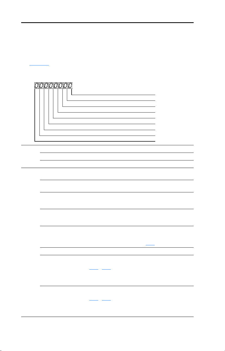
106 Rockwell Automation Publication 22D-UM001F-EN-E - September 2024
Chapter 3 Programming and Parameters
Enhanced Program Group (continued)
E248 [Enh Control Word]
Allows control of positioning and other functions via parameter control for use over comms. The
functions replicate the digital input options and function in the same way. For additional information,
see Appendix
F.
Important: The Find Home and Position Redefine bits must be returned to 0 following the homing
routine and before starting the drive.
Values Default: 0
Min/Max: 0/1
Display: 1
Bit 0 “Home Limit” In Positioning mode, this indicates the drive is at the home
position.
1 “Find Home” When set, the next start command causes the drive to find
home. Set this bit to 0 after completing the homing routine.
2 “Hold Step” In Positioning mode, this input over-rides other inputs and
causes the drive to remain at its current step (running at zero
speed once it reaches its position) until released.
3 “Pos Redefine” In Positioning mode, this input resets the home position to the
current position of the machine. Set this bit to 0 after
completing the homing routine.
4 “Sync Enable” Must be used in order to hold the existing frequency when
Sync Time is set to enable speed synchronization. When this
bit is reset to zero the drive will accelerate to the new
commanded frequency based on E214
[Sync Time] setting.
5 “Traverse Disable” When set the traverse function will be disabled.
6 “Logic In 1” This provides an identical function as the “Logic In1” Digital
Input option. This bit is logically ORed with a digital input
A051
…A054 set to option 23 “Logic In1”. It can be used to
move through the Step-Logic functions (speed or position) via
comms control without requiring actual digital input
transitions.
7 “Logic In 2” This provides and identical function as the “Logic In2” Digital
Input option. This bit is logically ORed with a digital input
A051
…A054 set to option 24 “Logic In2”. It can be used to
move through the Step-Logic functions (speed or position) via
comms control without requiring actual digital input
transitions.
1 = Input Present, 0 = Input Not Present
Home Limit Bit 0
Find Home Bit 1
Hold Step Bit 2
Pos Redefine Bit 3
Sync Enable Bit 4
Traverse Disable Bit 5
Logic In 1 Bit 6
Logic In 2 Bit 7

Rockwell Automation Publication 22D-UM001F-EN-E - September 2024 107
Chapter 3 Programming and Parameters
Enhanced Program Group (continued)
E249 [Cmd Stat Select]
Selects velocity-specific or position/fibers-specific Command and Status Word bit definitions for use
over a communication network. For additional information, see Appendix
C.
Options 0 “Velocity” (Default)
1 “Position”
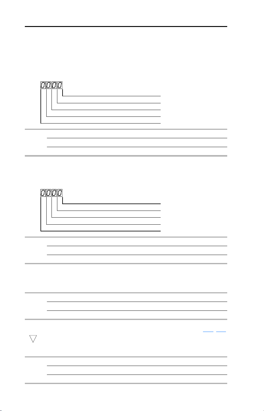
108 Rockwell Automation Publication 22D-UM001F-EN-E - September 2024
Chapter 3 Programming and Parameters
Advanced Display Group
d301 [Drive Status 2]
Present operating condition of the drive.
When in Positioning mode, Bit 10 indicates positive or negative position in relation to Home.
Values Default: Read Only
Min/Max: 0/1
Display: 1
1 = Condition True, 0 = Condition False
Dir Positive Bit 0
At Position Bit 1
At Home Bit 2
Drive Homed Bit 3
d302 [Fibers Status]
Present status of the Fibers features.
Values Default: Read Only
Min/Max: 0/1
Display: 1
1 = Condition True, 0 = Condition False
Sync Hold Digit 1
Sync Ramp Digit 2
Traverse On Digit 3
Traverse Dec Digit 4
d303 [Slip Hz Meter]
Displays the current amount of slip being applied to the motor frequency.
Values Default: Read Only
Min/Max: 0.0/25.0 Hz
Display: 0.1 Hz
d304 [Speed Feedback] Related Parameter(s): E218, d305
32-bit parameter.
Displays the value of the actual motor speed (whole number portion) whether measured by encoder/
pulse train feedback or estimated.
Values Default: Read Only
Min/Max: 0/64000 RPM
Display: 1 RPM
32

Rockwell Automation Publication 22D-UM001F-EN-E - September 2024 109
Chapter 3 Programming and Parameters
Advanced Display Group (continued)
d305 [Speed Feedback F] Related Parameter(s): d304
Displays the value of the actual motor speed (fractional portion) whether measured by encoder/pulse
train feedback or estimated.
Values Default: Read Only
Min/Max: 0.0/0.9
Display: 0.1
d306 [Encoder Speed] Related Parameter(s): d307
32-bit parameter.
Provides a monitoring point that reflects the speed (whole number portion) measured from the
feedback device. This shows the encoder or pulse train speed even if this is not used directly to
control the motor speed.
Values Default: Read Only
Min/Max: 0/64000
Display: 1
32
d307 [Encoder Speed F] Related Parameter(s): d306
Provides a monitoring point that reflects the speed (fractional portion) measured from the feedback
device. This shows the encoder or pulse train speed even if this is not used directly to control the
motor speed.
Values Default: Read Only
Min/Max: 0.0/0.9
Display: 0.1
d308 [Units Traveled H] Related Parameter(s): d309, E226
32-bit parameter.
Displays the number of user-defined units (whole number portion) traveled from the home position.
Values Default: Read Only
Min/Max: 0/64000
Display: 1
32
d309 [Units Traveled L] Related Parameter(s): d308, E226
Displays the number of user-defined units (fractional portion) traveled from the home position.
Values Default: Read Only
Min/Max: 0.00/0.99
Display: 0.01

110 Rockwell Automation Publication 22D-UM001F-EN-E - September 2024
Chapter 3 Programming and Parameters
d310 [Fault 4 Code] Related Parameter(s): A100
(With FRN 3.xx and later.)
A code that represents the fourth most recent drive fault. The codes will appear in these parameters in
the order they occur (b007
[Fault 1 Code] = the most recent fault). Repetitive faults will only be
recorded once. As faults occur, the value of this parameter will be moved to [Fault 5 Code] and this
parameter will be overwritten by [Fault 3 Code].
See Chapter
4 for fault code descriptions.
Values Default: Read Only
Min/Max: 0/122
Display: 1
d311 [Fault 5 Code] Related Parameter(s): A100
(With FRN 3.xx and later.)
A code that represents the fifth most recent drive fault. The codes will appear in these parameters in
the order they occur (b007
[Fault 1 Code] = the most recent fault). Repetitive faults will only be
recorded once. As faults occur, the value of this parameter will be moved to [Fault 6 Code] and this
parameter will be overwritten by [Fault 4 Code].
See Chapter
4 for fault code descriptions.
Values Default: Read Only
Min/Max: 0/122
Display: 1
d312 [Fault 6 Code] Related Parameter(s): A100
(With FRN 3.xx and later.)
A code that represents the sixth most recent drive fault. The codes will appear in these parameters in
the order they occur (b007
[Fault 1 Code] = the most recent fault). Repetitive faults will only be
recorded once. As faults occur, the value of this parameter will be moved to [Fault 7 Code] and this
parameter will be overwritten by [Fault 5 Code].
See Chapter
4 for fault code descriptions.
Values Default: Read Only
Min/Max: 0/122
Display: 1

Rockwell Automation Publication 22D-UM001F-EN-E - September 2024 111
Chapter 3 Programming and Parameters
d313 [Fault 7 Code] Related Parameter(s): A100
(With FRN 3.xx and later.)
A code that represents the seventh most recent drive fault. The codes will appear in these parameters
in the order they occur (b007
[Fault 1 Code] = the most recent fault). Repetitive faults will only be
recorded once. As faults occur, the value of this parameter will be moved to [Fault 8 Code] and this
parameter will be overwritten by [Fault 6 Code].
See Chapter
4 for fault code descriptions.
Values Default: Read Only
Min/Max: 0/122
Display: 1
d314 [Fault 8 Code] Related Parameter(s): A100
(With FRN 3.xx and later.)
A code that represents the eighth most recent drive fault. The codes will appear in these parameters
in the order they occur (b007
[Fault 1 Code] = the most recent fault). Repetitive faults will only be
recorded once. As faults occur, the value of this parameter will be moved to [Fault 9 Code] and this
parameter will be overwritten by [Fault 7 Code].
See Chapter
4 for fault code descriptions.
Values Default: Read Only
Min/Max: 0/122
Display: 1
d315 [Fault 9 Code] Related Parameter(s): A100
(With FRN 3.xx and later.)
A code that represents the ninth most recent drive fault. The codes will appear in these parameters in
the order they occur (b007
[Fault 1 Code] = the most recent fault). Repetitive faults will only be
recorded once. As faults occur, the value of this parameter will be moved to [Fault 10 Code] and this
parameter will be overwritten by [Fault 8 Code].
See Chapter
4 for fault code descriptions.
Values Default: Read Only
Min/Max: 0/122
Display: 1
d316 [Fault 10 Code] Related Parameter(s): A100
(With FRN 3.xx and later.)
A code that represents the tenth most recent drive fault. The codes will appear in these parameters in
the order they occur (b007
[Fault 1 Code] = the most recent fault). Repetitive faults will only be
recorded once. As faults occur, the value of this parameter will overwritten by [Fault 9 Code].
See Chapter
4 for fault code descriptions.
Values Default: Read Only
Min/Max: 0/122
Display: 1

112 Rockwell Automation Publication 22D-UM001F-EN-E - September 2024
Chapter 3 Programming and Parameters
Parameter Cross Reference – by Name
Parameter Name No. Group
10V Bipolar Enbl A123 Advanced Program
Accel Time 1 P039 Basic Program
Accel Time 2 A067 Advanced Program
Accel Time 3 E203 Enhanced Program
Accel Time 4 E205 Enhanced Program
Analog In 0-10V b020 Display
Analog In 4-20mA b021 Display
Analog In Loss A122 Advanced Program
Analog Out High A066 Advanced Program
Analog Out Sel A065 Advanced Program
Anlg In 0-10V Hi A111 Advanced Program
Anlg In 0-10V Lo A110 Advanced Program
Anlg In4-20mA Hi A113 Advanced Program
Anlg In4-20mA Lo A112 Advanced Program
Anlg Out Setpt A109 Advanced Program
Auto Rstrt Delay A093 Advanced Program
Auto Rstrt Tries A092 Advanced Program
Autotune A127 Advanced Program
Boost Select A084 Advanced Program
Break Frequency A087 Advanced Program
Break Voltage A086 Advanced Program
Bus Reg Mode A117 Advanced Program
Cmd Stat Select E249 Enhanced Program
Comm Data Rate A103 Advanced Program
Comm Format A107 Advanced Program
Comm Loss Action A105 Advanced Program
Comm Loss Time A106 Advanced Program
Comm Node Addr A104 Advanced Program
Comm Status b015 Display
Comm Write Mode E207 Enhanced Program
Commanded Freq b002 Display
Compensation A097 Advanced Program
Contrl In Status b013 Display
Control Source b012 Display
Control SW Ver b016 Display
Counter Status b025 Display
Counts Per Unit E226 Enhanced Program
Current Limit x A089, A118 Advanced Program
DB Resistor Sel A082 Advanced Program
DB Threshold A163 Advanced Program
DC Brake Level A081 Advanced Program
DC Brake Time A080 Advanced Program
DC Bus Voltage b005 Display
Decel Time 1 P040 Basic Program
Decel Time 2 A068 Advanced Program
Decel Time 3 E204 Enhanced Program
Decel Time 4 E206 Enhanced Program
Dig In Status b014 Display
Digital Inx Sel A051…A054 Advanced Program
Digital Term 3 E202 Enhanced Program
Drive Status b006 Display
Drive Status 2 d301 Advanced Display
Drive Temp b024 Display
Drive Type b017 Display
Elapsed Run Time b018 Display
EM Brk Off Delay A160 Advanced Program
EM Brk On Delay A161 Advanced Program
Encoder Pos Tol E225 Enhanced Program
Encoder PPR E218 Enhanced Program
Encoder Speed d306 Advanced Display
Encoder Speed F d307 Advanced Display
Enh Control Word E248 Enhanced Program
Fault Clear A100 Advanced Program
Fault x Code b007…b009 Display
Fault 4 Code d310 Advanced Display
Fault 5 Code d311 Advanced Display
Fault 6 Code d312 Advanced Display
Fault 7 Code d313 Advanced Display
Fault 8 Code d314 Advanced Display
Fault 9 Code d315 Advanced Display
Fault 10 Code d316 Advanced Display
Fibers Status d302 Advanced Display
Find Home Dir E224 Enhanced Program
Find Home Freq E223 Enhanced Program
Flux Current Ref A129 Advanced Program
Flying Start En A096 Advanced Program
Half Bus Enable E209 Enhanced Program
Internal Freq A069 Advanced Program
IR Voltage Drop A128 Advanced Program
Jog Accel/Decel A079 Advanced Program
Jog Frequency A078 Advanced Program
Ki Speed Loop E220 Enhanced Program
Kp Speed Loop E221 Enhanced Program
Language A108 Advanced Program
LED Display Opt E201 Enhanced Program
Max Traverse E210 Enhanced Program
Maximum Freq P035 Basic Program
Maximum Voltage A088 Advanced Program
Minimum Freq P034 Basic Program
MOP Reset Sel A162 Advanced Program
Motor Fdbk Type E216 Enhanced Program
Motor NP FLA A126 Advanced Program
Motor NP Hertz P032 Basic Program
Motor NP Poles E217 Enhanced Program
Motor NP Volts P031 Basic Program
Motor OL Current P033 Basic Program
Motor OL Ret P043 Basic Program
Motor OL Select A090 Advanced Program
Opto Out Logic A064 Advanced Program
Opto Outx Level A059, A062 Advanced Program
Opto Outx Sel A058, A061 Advanced Program
Output Current b003 Display
Output Freq b001 Display
Output Power b022 Display
Output Powr Fctr b023 Display
Output Voltage b004 Display
P Jump E213 Enhanced Program
PID Deadband A138 Advanced Program
PID Diff Rate A136 Advanced Program
PID Feedback Sel A133 Advanced Program
PID Integ Time A135 Advanced Program
PID Invert Error A164 Advanced Program
PID Preload A139 Advanced Program
PID Prop Gain A134 Advanced Program
PID Ref Sel A132 Advanced Program
PID Setpoint A137 Advanced Program
Parameter Name No. Group

Rockwell Automation Publication 22D-UM001F-EN-E - September 2024 113
Chapter 3 Programming and Parameters
PID Trim Hi A130 Advanced Program
PID Trim Lo A131 Advanced Program
Pos Reg Filter E246 Enhanced Program
Pos Reg Gain E247 Enhanced Program
Positioning Mode E222 Enhanced Program
Power Loss Mode E208 Enhanced Program
Preset Freq x A070…A077 Advanced Program
Process Display b010 Display
Process Factor A099 Advanced Program
Process Time Hi A116 Advanced Program
Process Time Lo A115 Advanced Program
Program Lock A101 Advanced Program
Pulse In Scale E219 Enhanced Program
PWM Frequency A091 Advanced Program
Relay Out Level A056 Advanced Program
Relay Out Sel A055 Advanced Program
Reset To Defalts P041 Basic Program
Reverse Disable A095 Advanced Program
S Curve % A083 Advanced Program
Skip Freq Band A120 Advanced Program
Skip Frequency A119 Advanced Program
Slip Hertz @ FLA A114 Advanced Program
Slip Hertz Meter d303 Advanced Display
Speed Feedback d304 Advanced Display
Speed Feedback F d305 Advanced Display
Speed Ratio E215 Enhanced Program
Speed Reference P038 Basic Program
Stall Fault Time A121 Advanced Program
Start At PowerUp A094 Advanced Program
Start Boost A085 Advanced Program
Start Source P036 Basic Program
Step Units 0 E230 Enhanced Program
Step Units 1 E232 Enhanced Program
Step Units 2 E234 Enhanced Program
Step Units 3 E236 Enhanced Program
Step Units 4 E238 Enhanced Program
Step Units 5 E240 Enhanced Program
Step Units 6 E242 Enhanced Program
Step Units 7 E244 Enhanced Program
Step Units F 0 E231 Enhanced Program
Step Units F 1 E233 Enhanced Program
Step Units F 2 E235 Enhanced Program
Step Units F 3 E237 Enhanced Program
Step Units F 4 E239 Enhanced Program
Step Units F 5 E241 Enhanced Program
Step Units F 6 E243 Enhanced Program
Step Units F 7 E245 Enhanced Program
Stop Mode P037 Basic Program
Stp Logic Status b028 Display
Stp Logic Time x A150…A157 Advanced Program
Stp Logic x A140…A147 Advanced Program
SW Current Trip A098 Advanced Program
Sync Time E214 Enhanced Program
Testpoint Data b019 Display
Testpoint Sel A102 Advanced Program
Timer Status b026 Display
Torque Current b029 Display
Torque Perf Mode A125 Advanced Program
Traverse Dec E212 Enhanced Program
Traverse Inc E211 Enhanced Program
Parameter Name No. Group
Units Traveled H d308 Advanced Display
Units Traveled L d309 Advanced Display
Var PWM Disable A124 Advanced Program
Voltage Class P042 Basic Program
Parameter Name No. Group

114 Rockwell Automation Publication 22D-UM001F-EN-E - September 2024
Chapter 3 Programming and Parameters
Notes:

Rockwell Automation Publication 22D-UM001F-EN-E - September 2024 115
Chapter 4
Troubleshooting
Chapter 4 provides information to guide you in troubleshooting the
PowerFlex 40P drive. Included is a listing and description of drive faults
(with possible solutions, when applicable).
The condition or state of your drive is constantly monitored. Any
changes will be indicated through the integral LED display.
LED Indications
See page 45 for information on drive status indicators and controls.
A fault is a condition that stops the drive. There are two fault types.
Table 14 – Fault Types
!
ATTENTION: Risk of injury or equipment damage exists. Drive does
not contain user-serviceable components. Do not disassemble drive
chassis.
Drive Status
Faults
Type Fault Description
➀
Auto-reset/Run When this type of fault occurs, and A092 [Auto Rstrt Tries] is
set to a value greater than “0,” a user-configurable timer, A093
[Auto Rstrt Delay], begins. When the timer reaches zero, the
drive attempts to automatically reset the fault. If the condition
that caused the fault is no longer present, the fault will be reset
and the drive will be restarted.
➁
Non-resetable This type of fault may require drive or motor repair, or is
caused by wiring or programing errors. The cause of the fault
must be corrected before the fault can be cleared.
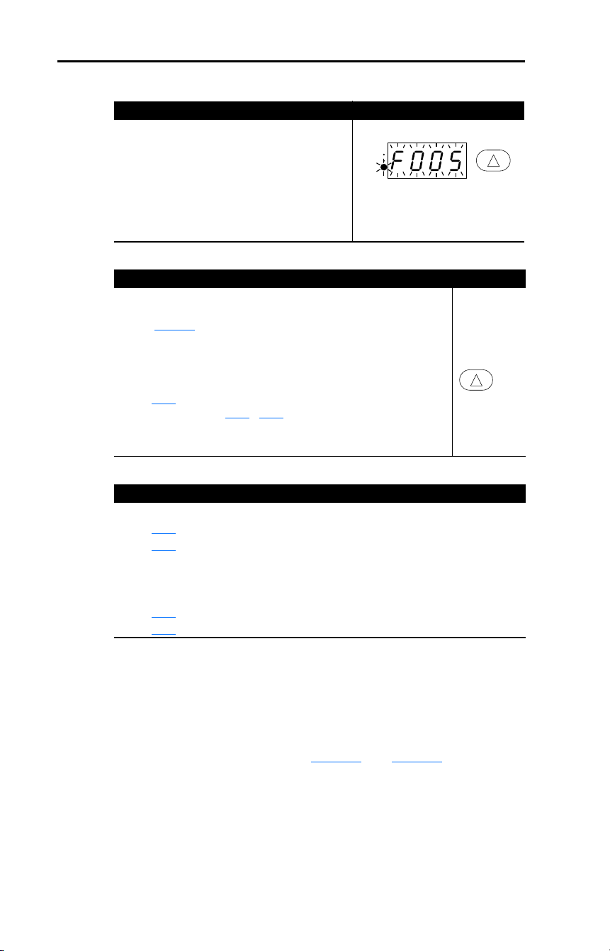
116 Rockwell Automation Publication 22D-UM001F-EN-E - September 2024
Chapter 4 Troubleshooting
Fault Indication
Manually Clearing Faults
Automatically Clearing Faults
Auto Restart (Reset/Run)
The Auto Restart feature provides the ability for the drive to
automatically perform a fault reset followed by a start attempt without
user or application intervention. This allows remote or “unattended”
operation. Only certain faults are allowed to be reset. Certain faults
(Type 2) that indicate possible drive component malfunction are not
resettable. Fault types are listed in Table 14
. See Table 15 for fault
descriptions.
Caution should be used when enabling this feature, since the drive will
attempt to issue its own start command based on user selected
programming.
Condition Display
Drive is indicating a fault.
The integral LED display provides visual
notification of a fault condition by displaying the
following.
• Flashing fault number
• Flashing fault indicator
Press the Up Arrow key to regain control of the
display.
Step Key(s)
1. Address the condition that caused the fault.
The cause must be corrected before the fault can be cleared.
See Table 15
.
2. After corrective action has been taken, clear the fault by one of these
methods.
• Press and hold the Up Arrow key for three seconds.
• Cycle drive power.
• Set A100
[Fault Clear] to “1” or “2”.
• Cycle digital input if A051
…A054 [Digital Inx Sel] is set to option 7
“Clear Fault”.
Option / Step
Clear a Type 1 fault and restart the drive.
1. Set A092
[Auto Rstrt Tries] to a value other than “0”.
2. Set A093
[Auto Rstrt Delay] to a value other than “0”.
Clear an OverVoltage, UnderVoltage or Heatsink OvrTmp fault
without restarting the drive.
1. Set A092
[Auto Rstrt Tries] to a value other than “0”.
2. Set A093
[Auto Rstrt Delay] to “0”.
RUN
REV
FAULT

Rockwell Automation Publication 22D-UM001F-EN-E - September 2024 117
Chapter 4 Troubleshooting
Fault Descriptions
Table 15 – Fault Types, Descriptions and Actions
No. Fault
Type
(1)
Description Action
F2 Auxiliary Input
➀
Auxiliary input interlock is open. 1. Check remote wiring.
2. Verify communications
programming for intentional fault.
F3 Power Loss
➁
DC bus voltage remained below
85% of nominal or single phase
operation detected.
1. Monitor the incoming AC line for
low voltage or line power
interruption.
2. Check input fuses.
F4 UnderVoltage
➀
DC bus voltage fell below the
minimum value.
Monitor the incoming AC line for low
voltage or line power interruption.
F5 OverVoltage
➀
DC bus voltage exceeded
maximum value.
Monitor the AC line for high line
voltage or transient conditions. Bus
overvoltage can also be caused by
motor regeneration. Extend the decel
time or install dynamic brake option.
F6 Motor Stalled
➀
Drive is unable to accelerate
motor.
Increase P039…A067 [Accel Time x]
or reduce load so drive output
current does not exceed the current
set by parameter A089
[Current Limit
1].
F7 Motor
Overload
➀
Internal electronic overload trip. 1. An excessive motor load exists.
Reduce load so drive output
current does not exceed the
current set by parameter P033
[Motor OL Current].
2. Verify A084
[Boost Select] setting
F8 Heatsink
OvrTmp
➀
Heatsink temperature exceeds a
predefined value.
1. Check for blocked or dirty heat
sink fins. Verify that ambient
temperature has not exceeded
40 °C (104 °F) for IP30/NEMA
1/UL Type 1 installations or 50 °C
(122 °F) for IP20/Open type
installations.
2. Check fan.
F12 HW
OverCurrent
➁
The drive output current has
exceeded the hardware current
limit.
Check programming. Check for
excess load, improper A084
[Boost
Select] setting, DC brake volts set
too high or other causes of excess
current.
F13 Ground Fault
➁
A current path to earth ground
has been detected at one or
more of the drive output
terminals.
Check the motor and external wiring
to the drive output terminals for a
grounded condition.
F29 Analog Input
Loss
➀
An analog input is configured to
fault on signal loss. A signal loss
has occurred.
Configure with A122
[Analog In
Loss].
1. Check parameters.
2. Check for broken/loose
connections at inputs.

118 Rockwell Automation Publication 22D-UM001F-EN-E - September 2024
Chapter 4 Troubleshooting
F33 Auto Rstrt Tries
➁
Drive unsuccessfully attempted
to reset a fault and resume
running for the programmed
number of A092
[Auto Rstrt
Tries].
Correct the cause of the fault and
manually clear.
F38 Phase U to
Gnd
➁
A phase to ground fault has been
detected between the drive and
motor in this phase.
1. Check the wiring between the
drive and motor.
2. Check motor for grounded phase.
3. Replace drive if fault cannot be
cleared.
F39 Phase V to
Gnd
F40 Phase W to
Gnd
F41 Phase UV
Short
➁
Excessive current has been
detected between these two
output terminals.
1. Check the motor and drive output
terminal wiring for a shorted
condition.
2. Replace drive if fault cannot be
cleared.
F42 Phase UW
Short
F43 Phase VW
Short
F48 Params
Defaulted
The drive was commanded to
write default values to EEPROM.
1. Clear the fault or cycle power to
the drive.
2. Program the drive parameters as
needed.
F63 SW
OverCurrent
➀
Programmed A098 [SW Current
Trip] has been exceeded.
Check load requirements and A098
[SW Current Trip] setting.
F64 Drive Overload
➁
Drive rating of 150% for 1 minute
or 200% for 3 seconds has been
exceeded.
Reduce load or extend Accel Time.
F70 Power Unit
➁
Failure has been detected in the
drive power section.
1. Cycle power.
2. Replace drive if fault cannot be
cleared.
F71 Net Loss The communication network has
faulted.
1. Cycle power.
2. Check communications cabling.
3. Check network adapter setting.
4. Check external network status.
F80 SVC Autotune The autotune function was either
cancelled by the user or failed.
Restart procedure.
F81 Comm Loss
➁
RS-485 (DSI) port stopped
communicating.
1. If adapter was not intentionally
disconnected, check wiring to the
port. Replace wiring, port
expander, adapters, or complete
drive as required.
2. Check connection.
3. An adapter was intentionally
disconnected.
4. Turn off using A105
[Comm Loss
Action].
5. Connecting I/O Terminal 04 to
ground may improve noise
immunity.
Table 15 – Fault Types, Descriptions and Actions (Continued)
No. Fault
Type
(1)
Description Action

Rockwell Automation Publication 22D-UM001F-EN-E - September 2024 119
Chapter 4 Troubleshooting
F91 Encoder Loss Requires differential encoder.
One of the 2 encoder channel
signals is missing.
1. Check Wiring.
2. If P038 [Speed Reference] = 9
“Positioning” and E216 [Motor
Fdbk Type] = 5 “Quad Check”
swap the Encoder channel inputs
(see page 29
) or swap any two
motor leads.
3. Replace encoder.
F100 Parameter
Checksum
➁
The checksum read from the
board does not match the
checksum calculated.
Set P041 [Reset To Defalts] to option
1 “Reset Defaults”.
F111 Enable
Hardware
DriveGuard Safe-Off Option
(Series B) board is installed and
the ENBL enable jumper has not
been removed.
1. Remove the ENBL enable
jumper.
2. Cycle power.
DriveGuard Safe-Off Option
(Series B) board has failed.
1. Remove power to the drive.
2. Replace DriveGuard Safe-Off
Option (Series B) board.
Hardware Enable circuitry has
failed.
Replace drive.
F122 I/O Board Fail
➁
Failure has been detected in the
drive control and I/O section.
1. Cycle power.
2. Replace drive if fault cannot be
cleared.
(1)
See page 115 for a description of fault types.
Table 15 – Fault Types, Descriptions and Actions (Continued)
No. Fault
Type
(1)
Description Action

120 Rockwell Automation Publication 22D-UM001F-EN-E - September 2024
Chapter 4 Troubleshooting
Motor does not Start.
Common Symptoms and Corrective Actions
Cause(s) Indication Corrective Action
No output voltage to the motor. None Check the power circuit.
• Check the supply voltage.
• Check all fuses and disconnects.
Check the motor.
• Verify that the motor is
connected properly.
Check the control input signals.
• Verify that a Start signal is
present. If 2-wire control is used,
verify that either the Run
Forward or Run Reverse signal
is active, but not both.
• Verify that I/O Terminal 01 is
active.
• Verify that P036
[Start Source]
matches your configuration.
• Verify that A095
[Reverse
Disable] is not prohibiting
movement.
• If using the DriveGuard Safe-Off
Option (Series B) board, verify
that inputs are active.
Improper boost setting at initial
start-up.
None Set A084
[Boost Select] to option 2
“35.0, VT”.
Drive is Faulted Flashing red status light Clear fault.
• Press and hold Up Arrow key for
3 seconds.
• Cycle power
• Set A100
[Fault Clear] to option 1
“Clear Faults”.
• Cycle digital input if A051
…A054
[Digital Inx Sel] is set to option 7
“Clear Fault”.

Rockwell Automation Publication 22D-UM001F-EN-E - September 2024 121
Chapter 4 Troubleshooting
Drive does not Start from Start or Run Inputs wired to the terminal block.
Drive does not respond to changes in speed command.
Cause(s) Indication Corrective Action
Drive is Faulted Flashing red status light Clear fault.
• Press and hold Up Arrow key for
3 seconds.
• Cycle power
• Set A100
[Fault Clear] to option 1
“Clear Faults”.
• Cycle digital input if A051
…A054
[Digital Inx Sel] is set to option 7
“Clear Fault”.
Incorrect programming.
• P036
[Start Source] is set to
option 5 “Comm Port”.
None Check parameter settings.
Incorrect input wiring.
See page 33
for wiring examples.
• 2-wire control requires Run
Forward, Run Reverse or Jog
input.
• 3-wire control requires Start and
Stop inputs
• Stop input is always required.
None Wire inputs correctly and/or install
jumper.
If using the DriveGuard Safe-Off
Option (Series B) board, verify that
inputs are active.
Incorrect Sink/Source DIP Switch
setting.
None Set switch to match wiring scheme.
Cause(s) Indication Corrective Action
No value is coming from the
source of the command.
The drive “Run” indicator is lit
and output is 0 Hz.
• Check b012
[Control Source] for
correct source.
• If the source is an analog input,
check wiring and use a meter to
check for presence of signal.
• Check b002
[Commanded Freq]
to verify correct command.
Incorrect reference source is
being selected via remote
device or digital inputs.
None • Check b012
[Control Source] for
correct source.
• Check b014
[Dig In Status] to
see if inputs are selecting an
alternate source. Verify settings
for A051
…A054 [Digital Inx Sel].
• Check P038
[Speed Reference]
for the source of the speed
reference. Reprogram as
necessary.
• Review the Speed Reference
Control chart on page 38
.

122 Rockwell Automation Publication 22D-UM001F-EN-E - September 2024
Chapter 4 Troubleshooting
Motor and/or drive will not accelerate to commanded speed.
Cause(s) Indication Corrective Action
Acceleration time is excessive. None Reprogram P039
[Accel Time 1] or
A067
[Accel Time 2].
Excess load or short
acceleration times force the
drive into current limit, slowing
or stopping acceleration.
None Compare b003
[Output Current] with
A089
[Current Limit 1].
Remove excess load or reprogram
P039
[Accel Time 1] or A067 [Accel
Time 2].
Check for improper A084
[Boost
Select] setting.
Speed command source or
value is not as expected.
None Verify b002
[Commanded Freq].
Check b012
[Control Source] for the
proper Speed Command.
Programming is preventing the
drive output from exceeding
limiting values.
None Check P035
[Maximum Freq] to
insure that speed is not limited by
programming.
Verify programming of E215
[Speed
Ratio].
Torque performance does not
match motor characteristics.
None Set motor nameplate full load amps
in parameter A126
[Motor NP FLA].
Perform A127
[Autotune] “Static
Tune” or “Rotate Tune” procedure.
Set A125
[Torque Perf Mode] to
option 0 “V/Hz”.

Rockwell Automation Publication 22D-UM001F-EN-E - September 2024 123
Chapter 4 Troubleshooting
Motor operation is unstable.
Drive will not reverse motor direction.
Drive does not power up.
Cause(s) Indication Corrective Action
Motor data was incorrectly
entered.
None 1. Correctly enter motor nameplate
data into P031
, P032 and P033.
2. Enable A097
[Compensation].
3. Use A084
[Boost Select] to
reduce boost level.
Cause(s) Indication Corrective Action
Digital input is not selected for
reversing control.
None Check [Digital Inx Sel]. See page 61
.
Choose correct input and program
for reversing mode.
Digital input is incorrectly
wired.
None Check input wiring. See page 28
Motor wiring is improperly
phased for reverse.
None Switch two motor leads.
Reverse is disabled. None Check A095
[Reverse Disable].
Cause(s) Indication Corrective Action
No input power to drive. None Check the power circuit.
• Check the supply voltage.
• Check all fuses and disconnects.
Jumper between I/O Terminals
P2 and P1 not installed and/or
DC Bus Inductor not
connected.
None Install jumper or connect DC Bus
Inductor.

124 Rockwell Automation Publication 22D-UM001F-EN-E - September 2024
Chapter 4 Troubleshooting
Notes:

Rockwell Automation Publication 22D-UM001F-EN-E - September 2024 125
Appendix A
Supplemental Drive Information
The tables on the following pages provide recommended AC line input
fuse and circuit breaker information. See Fusing and Circuit Breakers
below for UL and IEC requirements. Sizes listed are the recommended
sizes based on 40 °C (104 °F) and the U.S. N.E.C. Other country, state or
local codes may require different ratings.
Fusing
The recommended fuse types are listed below. If available current ratings
do not match those listed in the tables provided, choose the next higher
fuse rating.
• IEC – BS88 (British Standard) Parts 1 & 2
(1)
, EN60269-1, Parts 1 &
2, type gG or equivalent should be used.
• UL – UL Class CC, T, or J must be used.
(2)
Circuit Breakers
The “non-fuse” listings in the following tables include inverse time
circuit breakers, instantaneous trip circuit breakers (motor circuit
protectors) and 140M/140MT self-protected combination motor
controllers. If one of these is chosen as the desired protection method,
the following requirements apply:
• IEC – Both types of circuit breakers and 140M/140MT
self-protected combination motor controllers are acceptable for IEC
installations.
• UL – Only inverse time circuit breakers and the specified 140M/
140MT self-protected combination motor controllers are acceptable
for UL installations.
Drive, Fuse, and Circuit Breaker Ratings
(1)
Typical designations include, but may not be limited to the following; Parts 1 & 2: AC,
AD, BC, BD, CD, DD, ED, EFS, EF, FF, FG, GF, GG, GH.
(2)
Typical designations include; Type CC - KTK-R, FNQ-R
Type J - JKS, LPJ
Type T - JJS, JJN

126 Rockwell Automation Publication 22D-UM001F-EN-E - September 2024
Appendix A Supplemental Drive Information
Table 16 – Drive Ratings
Specifications
Catalog
Number
(1)
Output Ratings Input Ratings Branch Circuit Protection
kW (HP) Amps
Voltage
Range kVA Amps Fuses
140M/140MT
Motor
Protectors
(2)
(3)
Contactors
Min. Enclosure
Volume
(4)
(in.
3
)
200…240V AC (±10%) – 3-phase Input, 0…230V 3-phase Output
22D-B2P3 0.4 (0.5) 2.3 180-264 1.15 2.5 6
140M-C2E-B40
140MT-C3E-B40
100-C09
100-E09
1655
22D-B5P0 0.75 (1.0) 5.0 180-264 2.45 5.7 10
140M-C2E-C10
140MT-C3E-C10
100-C09
100-E09
1655
22D-B8P0 1.5 (2.0) 8.0 180-264 4.0 9.5 15
140M-C2E-C16
140MT-C3E-C16
100-C12
100-E12
1655
22D-B012 2.2 (3.0) 12.0 180-264 5.5 15.5 25
140M-C2E-C16
140MT-C3E-C16
100-C23
100-E26
1655
22D-B017 3.7 (5.0) 17.5 180-264 8.6 21.0 30 140M-F8E-C25
100-C23
100-E26
1655
22D-B024 5.5 (7.5) 24.0 180-264 11.8 26.1 40 140M-F8E-C32
100-C37
100-E38
2069
22D-B033 7.5 (10.0) 33.0 180-264 16.3 34.6 60 140M-F8E-C45
100-C60
100-E65
2069
380…480V AC (±10%) – 3-phase Input, 0…460V 3-phase Output
22D-D1P4 0.4 (0.5) 1.4 342-528 1.4 1.8 3
140M-C2E-B25
140MT-C3E-B25
100-C09
100-E09
1655
22D-D2P3 0.75 (1.0) 2.3 342-528 2.3 3.2 6
140M-C2E-B40
140MT-C3E-B40
100-C09
100-E09
1655
22D-D4P0 1.5 (2.0) 4.0 342-528 4.0 5.7 10
140M-C2E-B63
140MT-C3E-B63
100-C09
100-E09
1655
22D-D6P0 2.2 (3.0) 6.0 342-528 5.9 7.5 15
140M-C2E-C10
140MT-C3E-C10
100-C09
100-E09
1655
22D-D010 4.0 (5.0) 10.5 342-528 10.3 13.0 20
140M-C2E-C16
140MT-C3E-C16
100-C23
100-E26
1655
22D-D012 5.5 (7.5) 12.0 342-528 11.8 14.2 25
140M-D8E-C20
140MT-D9E-C20
100-C23
100-E26
2069
22D-D017 7.5 (10.0) 17.0 342-528 16.8 18.4 30
140M-D8E-C20
140MT-D9E-C20
100-C23
100-E26
2069
22D-D024 11.0 (15.0) 24.0 342-528 23.4 26.0 50 140M-F8E-C32
100-C43
100-E40
2069
460…600V AC (±10%) – 3-phase Input, 0…575V 3-phase Output
22D-E1P7 0.75 (1.0) 1.7 414-660 2.1 2.3 6
140M-C2E-B25
140MT-C3E-B25
100-C09
100-E09
1655
22D-E3P0 1.5 (2.0) 3.0 414-660 3.65 3.8 6
140M-C2E-B40
140MT-C3E-B40
100-C09
100-E09
1655
22D-E4P2 2.2 (3.0) 4.2 414-660 5.2 5.3 10
140M-D8E-B63
140MT-D9E-B63
100-C09
100-E09
1655
22D-E6P6 4.0 (5.0) 6.6 414-660 8.1 8.3 15
140M-D8E-C10
140MT-D9E-C10
100-C09
100-E09
1655
22D-E9P9 5.5 (7.5) 9.9 414-660 12.1 11.2 20
140M-D8E-C16
140MT-D9E-C16
100-C16
100-E16
2069
22D-E012 7.5 (10.0) 12.2 414-660 14.9 13.7 25
140M-D8E-C16
140MT-D9E-C16
100-C23
100-E26
2069
22D-E019 11.0 (15.0) 19.0 414-660 23.1 24.1 40 140M-F8E-C25
100-C30
100-E30
2069
(1)
Ratings apply to all drive types; Panel Mount (N104), Flange Mount (F104), and Plate Drive (H204).
(2)
The AIC ratings of the Bulletin 140M/140MT devices can vary. See Motor Protection Circuit Breaker and Motor
Circuit Protector Specifications Technical Data, publication 140-TD005
or 140M-TD002.
(3)
Manual Self-protected (Type E) Combination Motor Controller, UL listed for 208 Wye or Delta, 240 Wye or Delta,
480Y/277 or 600Y/347. Not UL listed for use on 480V or 600V Delta/Delta, corner ground, or high-resistance
ground systems.
(4)
When using a Manual Self-protected (Type E) Combination Motor Controller, the drive must be installed in a
ventilated or non-ventilated enclosure with the minimum volume specified in this column. Application specific
thermal considerations may require a larger enclosure.
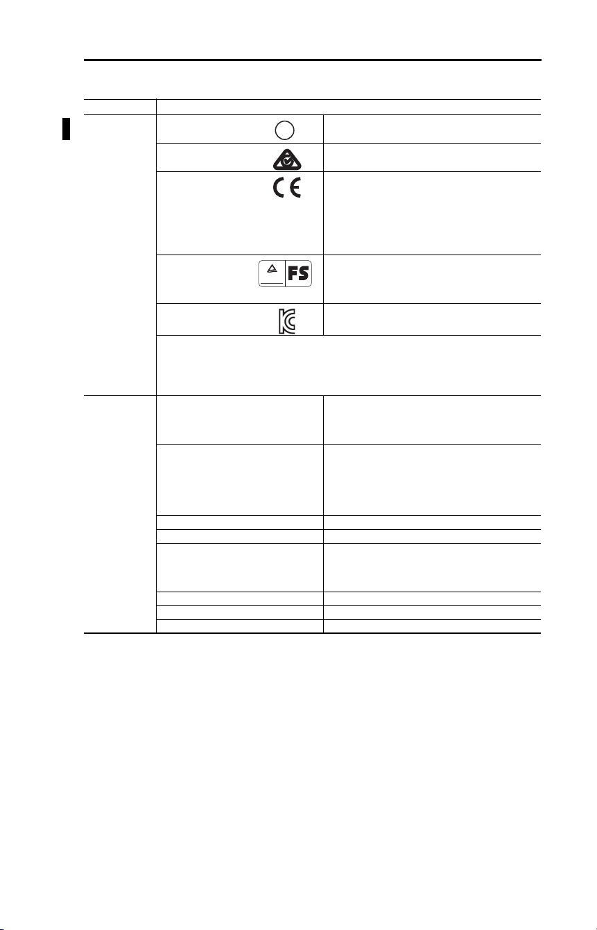
Rockwell Automation Publication 22D-UM001F-EN-E - September 2024 127
Appendix A Supplemental Drive Information
Table 17 – Specifications
Category Specification
Agency
Certification
Listed to UL508C and CAN/CSA-22.2
Certified to AS/NZS, 1997 Group 1, Class A
Marked for all applicable European Directives
EMC Directive: 2014/30/EU:
EN 61800-3:
LV Directive: 2014/35/EU:
EN 61800-5-1
Machine Directive: 2006/42/EC:
EN 62061
Certified to EN ISO 13849-1:2008+AC:2009;
Performance Level d (Safety Category 3) and SIL 2
Meets Functional Safety (FS) when used with the
DriveGuard Safe-Off Option (Series B).
KCC-REM-RAA-22D
The drive is also designed to meet the appropriate portions of the following specifications:
NFPA 70 - US National Electrical Code
NEMA ICS 3.1 - Safety standards for Construction and Guide for Selection, Installation and
Operation of Adjustable Speed Drive Systems.
IEC 146 - International Electrical Code.
Protection Bus Overvoltage Trip
200…240V AC Input:
380…460V AC Input:
460…600V AC Input:
405V DC bus (equivalent to 290V AC incoming line)
810V DC bus (equivalent to 575V AC incoming line)
1005V DC bus (equivalent to 711V AC incoming line)
Bus Undervoltage Trip
200…240V AC Input:
380…480V AC Input:
460…600V AC Input
P042 = 3 “High Voltage”:
P042 = 2 “Low Voltage”:
210V DC bus (equivalent to 150V AC incoming line)
390V DC bus (equivalent to 275V AC incoming line)
487V DC bus (equivalent to 344V AC incoming line)
390V DC bus (equivalent to 275V AC incoming line)
Power Ride-through: 100 milliseconds
Logic Control Ride-through: 0.5 seconds minimum, 2 seconds typical
Electronic Motor Overload Protection: Provides class 10 motor overload protection according
to NEC article 430 and motor over-temperature
protection according to NEC article 430.126 (A) (2).
UL 508C File 29572.
Overcurrent: 200% hardware limit, 300% instantaneous fault
Ground Fault Trip: Phase-to-ground on drive output
Short Circuit Trip: Phase-to-phase on drive output
U
L
®
CUS
TUV
Rheinland
.
.
Functional
Safety
Bauart geprüft
Type approved

128 Rockwell Automation Publication 22D-UM001F-EN-E - September 2024
Appendix A Supplemental Drive Information
Environment Altitude: 1000 m (3300 ft) max. without derating. Above 1000 m
(3300 ft) derate 3% for every 305 m (1000 ft).
Maximum Surrounding Air Temperature
without derating:
IP20, Open Type:
IP30, NEMA Type 1, UL Type 1:
Flange and Plate Mount:
–10…+50 °C (14…122 °F)
–10…+40 °C (14…104 °F)
Heatsink: –10…+40 °C (14…104 °F)
Drive: –10…+50 °C (14…122 °F)
Cooling Method
Convection:
Fan:
0.4 kW (0.5 HP) drives and all Flange and Plate drives
All other drive ratings
Storage Temperature: –40…+85 °C (–40…+185 °F)
Atmosphere: Important: Drive must
not be installed in an area
where the ambient atmosphere contains volatile or
corrosive gas, vapors or dust. If the drive is not going
to be installed for a period of time, it must be stored in
an area where it will not be exposed to a corrosive
atmosphere.
Relative Humidity: 0…95% non-condensing
Shock (operating): 15 g peak for 11 ms duration (±1.0 ms)
Vibration (operating): 1 g peak, 5 to 2000 Hz
Electrical Voltage Tolerance: 200…240V ±10%
380…480V ±10%
460…600V ±10%
Frequency Tolerance: 48-63 Hz
Input Phases: Three-phase input provides full rating. Single-phase
operation provides 35% rated current.
Displacement Power Factor: 0.98 across entire speed range
Maximum Short Circuit Rating: 100,000 Amps Symmetrical
Actual Short Circuit Rating: Determined by AIC Rating of installed fuse/circuit
breaker
Transistor Type: Isolated Gate Bipolar (IGBT)
Control Method: Sinusoidal PWM, Volts/Hertz, and Sensorless Vector
Carrier Frequency 2…16 kHz, Drive rating based on 4 kHz.
Frequency Accuracy
Digital Input:
Analog Input:
Analog Output:
Within ±0.05% of set output frequency
Within 0.5% of maximum output frequency, 10-bit
resolution
±2% of full scale, 10-bit resolution
Speed Regulation
Open Loop with Slip Compensation:
With Encoder:
±1% of base speed across a 80:1 speed range
±0.3% of base speed across a 80:1 speed range
±0.05% of base speed across a 20:1 speed range
Output Frequency: 0-500 Hz (programmable)
Efficiency: 97.5% (typical)
Stop Modes: Multiple programmable stop modes including - Ramp,
Coast, DC-Brake, and Ramp-to-Stop
Accel/Decel: Four independently programmable accel and decel
times. Each time may be programmed from 0…600
seconds in 0.1 second increments.
Intermittent Overload: 150% Overload capability for up to 1 minute
200% Overload capability for up to 3 seconds
Electronic Motor Overload Protection Provides class 10 motor overload protection according
to NEC article 430 and motor over-temperature
protection according to NEC article 430.126 (A) (2).
UL 508C File 29572.
Category Specification

Rockwell Automation Publication 22D-UM001F-EN-E - September 2024 129
Appendix A Supplemental Drive Information
Control Inputs Digital: Bandwidth: 10 Rad/Secs for open and closed loop
Quantity: (2) Dedicated for start and stop
(5) Programmable
Current: 6 mA
Type
Source Mode (SRC):
Sink Mode (SNK):
18…24V = ON, 0…6V = OFF
0…6V = ON, 18…24V = OFF
Analog: Quantity: (2) Isolated, –10…+10V and 4…20 mA
Specification
Resolution:
0…10V DC Analog:
4…20 mA Analog:
External Pot:
10-bit
100 kΩ input impedance
250 Ω input impedance
1…10 kΩ, 2 Watt minimum
Encoder Type: Incremental, dual channel
Supply: 12V, 250 mA. 12V, 10 mA minimum inputs isolated
with differential transmitter, 250 kHz maximum.
Quadrature: 90°, ±27° at 25 °C (77 °F).
Duty Cycle: 50%, +10%
Requirements: Encoders must be line driver type, quadrature (dual
channel) or pulse (single channel), 3.5…26V DC
output, single-ended or differential and capable of
supplying a minimum of 10 mA per channel. Allowable
input is DC up to a maximum frequency of 250 kHz.
The encoder I/O automatically scales to allow 5V, 12V
and 24V DC nominal voltages.
Control Outputs Relay: Quantity: (1) Programmable Form C
Specification
Resistive Rating:
Inductive Rating:
3.0 A at 30V DC, 3.0 A at 125V, 3.0 A at 240V AC
0.5 A at 30V DC, 0.5 A at 125V, 0.5 A at 240V AC
Opto: Quantity:
(2) Programmable
Specification: 30V DC, 50 mA Non-inductive
Analog: Quantity: (1) Non-isolated 0…10V or 4…20 mA
Specification
Resolution:
0…10V DC Analog:
4…20 mA Analog:
10-bit
1 kΩ minimum
525 Ω maximum
Category Specification

130 Rockwell Automation Publication 22D-UM001F-EN-E - September 2024
Appendix A Supplemental Drive Information
Table 18 – PowerFlex 40P Estimated Watts Loss (Rated Load, Speed, and PWM)
Voltage kW (HP) External Watts Internal Watts Total Watts Loss
200…240V 0.4 (0.5)
0.75 (1.0)
1.1 (2.0)
2.2 (3.0)
3.7 (5.0)
5.5 (7.5)
7.5 (10)
22
40
63
100
150
200
265
18
20
22
25
30
35
40
40
60
85
125
180
235
305
380…480V 0.4 (0.5)
0.75 (1.0)
1.1 (2.0)
2.2 (3.0)
3.7 (5.0)
5.5 (7.5)
7.5 (10)
11 (15)
17
30
48
75
135
140
175
260
18
20
22
25
25
35
35
40
35
50
70
100
160
175
210
300
460…600V 0.75 (1.0)
1.5 (2.0)
2.2 (3.0)
4.0 (5.0)
5.5 (7.5)
7.5 (10)
11 (15)
30
48
75
135
140
175
260
20
22
25
25
35
35
40
50
70
100
160
175
210
300

Rockwell Automation Publication 22D-UM001F-EN-E - September 2024 131
Appendix B
Accessories and Dimensions
Table 19 – Catalog Number Description
Table 20 – PowerFlex 40P Drives
Product Selection
22D - B 2P3 N 1 0 4
Drive Voltage Rating Rating Enclosure HIM Emission Class Version
Drive Ratings IP20/NEMA Type Open
IP20 Flange
Mount
(1)
Plate Drive
Input Voltage kW HP
Output
Current
(Amps) Catalog Number
Frame
Size Catalog Number Catalog Number
240V 50/60 Hz
3-phase
No Filter
0.4 0.5 2.3 22D-B2P3N104 B 22D-B2P3F104 22D-B2P3H204
0.75 1.0 5.0 22D-B5P0N104 B 22D-B5P0F104 22D-B5P0H204
1.5 2.0 8.0 22D-B8P0N104 B 22D-B8P0F104 22D-B8P0H204
2.2 3.0 12.0 22D-B012N104 B 22D-B012F104 22D-B012H204
3.7 5.0 17.5 22D-B017N104 B 22D-B017F104 22D-B017H204
5.5 7.5 24.0 22D-B024N104 C 22D-B024F104 22D-B024H204
7.5 10.0 33.0 22D-B033N104 C 22D-B033F104 22D-B033H204
480V 50/60 Hz
3-phase
No Filter
0.4 0.5 1.4 22D-D1P4N104 B 22D-D1P4F104 22D-D1P4H204
0.75 1.0 2.3 22D-D2P3N104 B 22D-D2P3F104 22D-D2P3H204
1.5 2.0 4.0 22D-D4P0N104 B 22D-D4P0F104 22D-D4P0H204
2.2 3.0 6.0 22D-D6P0N104 B 22D-D6P0F104 22D-D6P0H204
4.0 5.0 10.5 22D-D010N104 B 22D-D010F104 22D-D010H204
5.5 7.5 12.0 22D-D012N104 C 22D-D012F104 22D-D012H204
7.5 10.0 17.0 22D-D017N104 C 22D-D017F104 22D-D017H204
11.0 15.0 24.0 22D-D024N104 C 22D-D024F104
(2)
22D-D024H204
(42)
600V 50/60 Hz
3-phase
No Filter
0.75 1.0 1.7 22D-E1P7N104 B 22D-E1P7F104 22D-E1P7H204
1.5 2.0 3.0 22D-E3P0N104 B 22D-E3P0F104 22D-E3P0H204
2.2 3.0 4.2 22D-E4P2N104 B 22D-E4P2F104 22D-E4P2H204
4.0 5.0 6.6 22D-E6P6N104 B 22D-E6P6F104 22D-E6P6H204
5.5 7.5 9.9 22D-E9P9N104 C 22D-E9P9F104 22D-E9P9H204
7.5 10.0 12.0 22D-E012N104 C 22D-E012F104 22D-E012H204
11.0 15.0 19.0 22D-E019N104 C 22D-E019F104 22D-E019H204
(1)
Meets IP40/54/65 (NEMA 1/12/4/4X) when installed in an enclosure of like rating.
(2)
Requires use of external DC Bus Inductor or AC Line Reactor. See Table 23 for details.

132 Rockwell Automation Publication 22D-UM001F-EN-E - September 2024
Appendix B Accessories and Dimensions
Table 21 – Dynamic Brake Resistors
Drive Ratings
Catalog Number
(1)(2)
Fuse Protection
(3)
Input Voltage kW HP
Minimum
Resistance
Ω BR- DC+/BR+ DC-
240V 50/60 Hz
3-phase
0.4 0.5 48 AK-R2-091P500 PV-12A10F 1000GH-016 1000GH-016
0.75 1.0 48 AK-R2-091P500 PV-12A10F 1000GH-016 1000GH-016
1.5 2.0 48 AK-R2-091P500 PV-12A10F 1000GH-025 1000GH-025
2.2 3.0 32 AK-R2-047P500 PV-20A10F 1000GH-032 1000GH-032
3.7 5.0 19 AK-R2-047P500 PV-30A10F 1000GH-040 1000GH-040
5.5 7.5 13 AK-R2-030P1K2 PV-50A10F 1000GH-050 1000GH-050
7.5 10.0 10 AK-R2-030P1K2 PV-63A10F 1000GH-063 1000GH-063
480V 50/60 Hz
3-phase
0.4 0.5 97 AK-R2-360P500 PV-12A10F 1000GH-016 1000GH-016
0.75 1.0 97 AK-R2-360P500 PV-12A10F 1000GH-016 1000GH-016
1.5 2.0 97 AK-R2-360P500 PV-12A10F 1000GH-016 1000GH-016
2.2 3.0 97 AK-R2-120P1K2 PV-12A10F 1000GH-016 1000GH-016
4.0 5.0 77 AK-R2-120P1K2 PV-15A10F 1000GH-032 1000GH-032
5.5 7.5 55 AK-R2-120P1K2 PV-20A10F 1000GH-040 1000GH-040
7.5 10.0 39 AK-R2-120P1K2 PV-30A10F 1000GH-040 1000GH-040
11.0 15.0 24 AK-R2-120P1K2
(4)
PV-50A10F 1000GH-050 1000GH-050
600V 50/60 Hz
3-phase
0.75 1.0 120 AK-R2-360P500 PV-10A10F 1000GH-016 1000GH-016
1.5 2.0 120 AK-R2-360P500 PV-10A10F 1000GH-016 1000GH-016
2.2 3.0 82 AK-R2-120P1K2 PV-15A10F 1000GH-016 1000GH-016
4.0 5.0 82 AK-R2-120P1K2 PV-15A10F 1000GH-025 1000GH-025
5.5 7.5 51 AK-R2-120P1K2 PV-20A10F 1000GH-025 1000GH-025
7.5 10.0 51 AK-R2-120P1K2 PV-20A10F 1000GH-032 1000GH-032
11.0 15.0 51 AK-R2-120P1K2
(4)
PV-20A10F 1000GH-040 1000GH-040
(1)
The resistors listed in this tables are rated for 5% duty cycle.
(2)
Use of Rockwell Automation resistors is always recommended. The resistors listed have been carefully selected
for optimizing performance in a variety of applications. Alternative resistors may be used, however care must be
taken when making a selection. See the PowerFlex Dynamic Braking Resistor Calculator Application Technique,
publication PFLEX-AT001
.
(3)
For IEC applications, DC Fuse is mandatory when these terminals are connected. Connect the fuse close to the
terminal. Use the specified part number. PV-xxxxxx fuse is from Bussman. 1000GH-xxx fuse is from Hinode.
(4)
Requires two resistors that are wired in parallel.
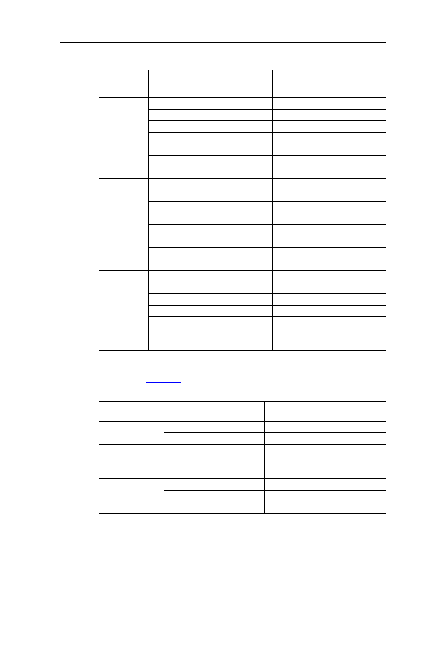
Rockwell Automation Publication 22D-UM001F-EN-E - September 2024 133
Appendix B Accessories and Dimensions
Table 22 – Bulletin 1321-3R Series Line Reactors
Table 23 – DC Bus Inductors
Input Voltage kW HP
Fundamental
Amps
Maximum
Continuous
Amps
Inductance
mh
Watts
Loss
Catalog
Number
(1)
(1)
Catalog numbers listed are for 3% impedance open style units. NEMA Type 1 and 5% impedance
reactor types are also available. See 1321 Power Conditioning Products Technical Data,
publication 1321-TD001
.
240V 50/60 Hz
3-phase
0.4 0.5 4 6 12.0 21 W 1321-3R4-D
0.75 1.0 8 12 3.0 29 W 1321-3R8-B
1.5 2.0 8 12 1.5 19.5 W 1321-3R8-A
2.2 3.0 12 18 1.25 26 W 1321-3R12-A
3.7 5.0 18 27 0.8 36 W 1321-3R18-A
5.5 7.5 25 37.5 0.5 48 W 1321-3R25-A
7.5 10.0 35 52.5 0.4 49 W 1321-3R35-A
480V 50/60 Hz
3-phase
0.4 0.5 2 3 20.0 11.3 W 1321-3R2-B
0.75 1.0 4 6 9.0 20 W 1321-3R4-C
1.5 2.0 4 6 6.5 20 W 1321-3R4-B
2.2 3.0 8 12 5.0 25.3 W 1321-3R8-C
4.0 5.0 12 18 2.5 31 W 1321-3R12-B
5.5 7.5 12 18 2.5 31 W 1321-3R12-B
7.5 10.0 18 27 1.5 43 W 1321-3R18-B
11.0 15.0 25 37.5 1.2 52 W 1321-3R25-B
600V 50/60 Hz
3-phase
0.75 1.0 2 3 20.0 11.3 W 1321-3R2-B
1.5 2.0 4 6 6.5 20 W 1321-3R4-B
2.2 3.0 4 6 6.5 20 W 1321-3R4-B
4.0 5.0 8 12 5.0 25.3 W 1321-3R8-C
5.5 7.5 12 18 2.5 31 W 1321-3R12-B
7.5 10.0 12 18 2.5 31 W 1321-3R12-B
11.0 15.0 18 27 1.5 43 W 1321-3R18-B
Input Voltage kW HP Amps
Inductance
mh Catalog Number
240V 50/60 Hz
3-phase
5.5 7.5 32 0.85 1321-DC32-1
7.5 10.0 40 0.5 1321-DC40-2
480V 50/60 Hz
3-phase
5.5 7.5 18 3.75 1321-DC18-4
7.5 10.0 25 4.0 1321-DC25-4
11.0 15.0 32 2.68 1321-DC32-3
600V 50/60 Hz
3-phase
5.5 7.5 12 6.0 1321-DC12-2
7.5 10.0 18 6.0 1321-DC18-4
11.0 15.0 25 4.0 1321-DC25-4

134 Rockwell Automation Publication 22D-UM001F-EN-E - September 2024
Appendix B Accessories and Dimensions
Table 24 – EMC Line Filters
Drive Ratings
S Type Filter
Catalog Number
(1)
(1)
This filter is suitable for use with a cable length of at least 10 m (33 ft) for Class A and 1 m (3.3 ft)
for Class B environments.
L Type Filter
Catalog Number
(2)
(2)
This filter is suitable for use with a cable length of at least 100 m (328 ft) for Class A and 5 m (16 ft)
for Class B environments.
Input Voltage kW HP
240V 50/60 Hz
3-phase
0.4 0.5 22-RF021-BS 22-RF021-BL
(3)
(3)
Filter must be Series C or later.
0.75 1.0 22-RF021-BS 22-RF021-BL
(43)
1.5 2.0 22-RF021-BS 22-RF021-BL
(43)
2.2 3.0 22-RF021-BS 22-RF021-BL
(43)
3.7 5.0 22-RF021-BS 22-RF021-BL
(43)
5.5 7.5 22-RF034-CS 22-RF034-CL
7.5 10.0 22-RF034-CS 22-RF034-CL
480V 50/60 Hz
3-phase
0.4 0.5 22-RF012-BS 22-RF012-BL
0.75 1.0 22-RF012-BS 22-RF012-BL
1.5 2.0 22-RF012-BS 22-RF012-BL
2.2 3.0 22-RF012-BS 22-RF012-BL
4.0 5.0 22-RF012-BS 22-RF012-BL
5.5 7.5 22-RF018-CS
(43)
22-RF018-CL
7.5 10.0 22-RF018-CS
(43)
22-RF018-CL
11.0 15.0 22-RF026-CS
(43)
22-RF026-CL
600V 50/60 Hz
3-phase
0.75 1.0 – 22-RF8P0-BL
1.5 2.0 – 22-RF8P0-BL
2.2 3.0 – 22-RF8P0-BL
4.0 5.0 – 22-RF8P0-BL
5.5 7.5 – 22-RF015-CL
7.5 10.0 – 22-RF015-CL
11.0 15.0 – 22-RF024-CL

Rockwell Automation Publication 22D-UM001F-EN-E - September 2024 135
Appendix B Accessories and Dimensions
Table 25 – Human Interface Module (HIM) Option Kits and Accessories
Table 26 – IP30/NEMA 1/UL Type 1 Kit
Table 27 – Other Options
Item Description Catalog Number
LCD Display, Remote Panel
Mount
Digital speed control
CopyCat capable
IP66 (NEMA Type 4X/12) indoor use only
Includes 2.9 m (9.51 ft) cable
22-HIM-C2S
LCD Display, Remote Handheld Digital speed control
Full numeric keypad
CopyCat capable
IP30 (NEMA Type 1)
Includes 1.0 m (3.3 ft) cable
Panel mount with optional bezel kit
22-HIM-A3
Bezel Kit Panel mount for LCD display, remote
handheld unit, IP30 (NEMA Type 1)
22-HIM-B1
DSI HIM Cable
(DSI HIM to RJ45 cable)
1.0 m (3.3 ft)
2.9 m (9.51 ft)
22-HIM-H10
22-HIM-H30
Item Description
Drive
Frame Catalog Number
IP30/NEMA 1/UL Type 1
Kit
Field installed kit. Converts drive to IP30/
NEMA 1/UL Type 1 enclosure. Includes
conduit box with mounting screws and
plastic top panel.
B 22-JBAB
C 22-JBAC
IP30/NEMA 1/UL Type 1
Kit for Communication
Option
Field installed kit. Converts drive to IP30/
NEMA 1/UL Type 1 enclosure. Includes
communication option conduit box with
mounting screws and plastic top panel.
B22-JBCB
C22-JBCC
Item Description Catalog Number
DriveGuard Safe-Off Option
Board
When used with suitable safety components,
provides protection according to EN ISO
13849-1:2008 +AC:2009; Category 3 for
safe off and protection against restart.
20A-DG01
Table 28 – Communication Option Kits and Accessories
Item Description Catalog Number
Communication
Adapters
Embedded communication options for use with the
PowerFlex 4-class drives.
Requires a Communication Adapter Cover
(Ordered Separately).
ControlNet®
DeviceNet®
EtherNet/IP™
LonWorks
PROFIBUS DP
22-COMM-C
22-COMM-D
22-COMM-E
22-COMM-L
22-COMM-P
External DSI
Communications Kit
External mounting kit for 22-COMM cards 22-XCOMM-DC-BASE
External Comms Power
Supply
Optional 100…240V AC power supply for external
DSI communications kit
20-XCOMM-AC-PS1
Compact I/O Module Three channel 1769-SM2
Communication Adapter
Cover
Cover that houses the communication adapter.
B-frame Drive
C-frame Drive
22D-CCB
22D-CCC

136 Rockwell Automation Publication 22D-UM001F-EN-E - September 2024
Appendix B Accessories and Dimensions
Universal Serial Bus
(USB) Converter Module
Provides serial communication via DF1 protocol
for use with Connected Components Workbench
and DriveTools SP software. Includes:
2 m USB cable (1)
20-HIM-H10 cable (1)
22-HIM-H10 cable (1)
1203-USB
DSI Cable 2.0 m (6.5 ft) RJ45 to RJ45 cable, male to male
connectors
22-RJ45CBL-C20
Splitter Cable RJ45 one to two port splitter cable AK-U0-RJ45-SC1
Terminating Resistors RJ45 120 Ω resistors (2 pieces) AK-U0-RJ45-TR1
Terminal Block RJ45 Two-position terminal block (5 pieces) AK-U0-RJ45-TB2P
Table 29 – Programming Software
Item Description
Connected Components
Workbench Software
Windows-based software packages for programming and configuring
Allen-Bradley drives and other Rockwell Automation products.
Compatibility: Microsoft Windows® Server 2012
(1)
, Windows Server
2012 R2, Windows Server 2016
(1)
, Windows Server 2019, Windows 10
IoT Enterprise 2016 Long-Term Servicing Branch (LTSB) 64-bit,
Windows 10 IoT Enterprise 2019 Long-Term Servicing Channel (LTSC),
Windows 10, and Windows 11
(2)
.
All supported operating systems require .NET Framework 3.5 SP1 to be
installed.
You can download Connected Components Workbench Standard Edition
software for free at rok.auto/pcdc
.
To purchase Connected Components Workbench Developer Edition
software, visit rok.auto/ccw
.
(1)
Requires Connected Components Workbench software version 20.01.00 or earlier.
(2)
Requires Connected Components Workbench software version 20.01.00 or later.
DriveExecutive™ Software
(Download as part of the
DriveTools SP software
package)
Windows-based software package that provides an intuitive means for
monitoring or configuring Allen-Bradley drives and communication
adapters online and offline.
Compatibility: Microsoft Windows 7, Windows 10, and Windows Server
2019
You can download DriveTools SP Standard Edition software at
rok.auto/pcdc
.
Table 28 – Communication Option Kits and Accessories (Continued)
Item Description Catalog Number
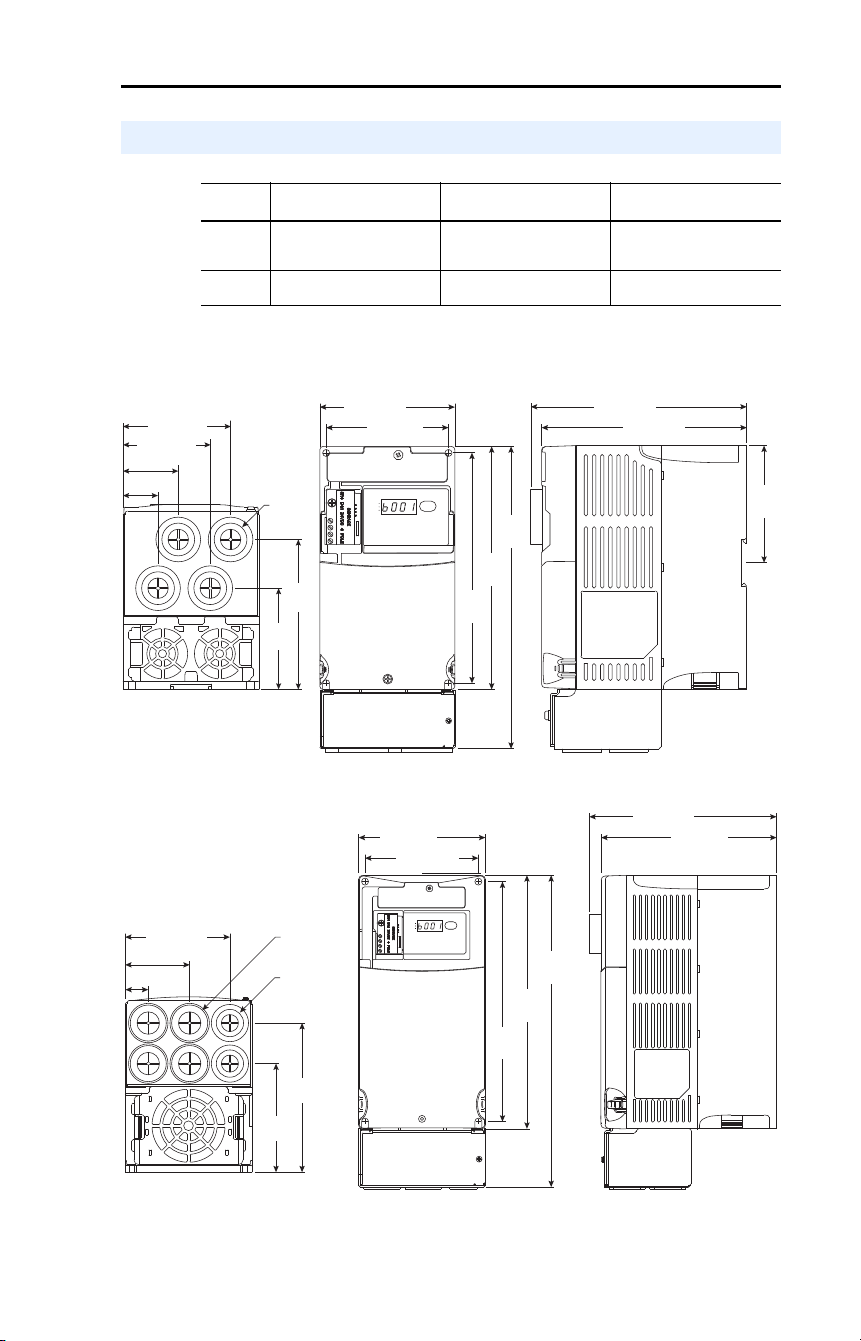
Rockwell Automation Publication 22D-UM001F-EN-E - September 2024 137
Appendix B Accessories and Dimensions
Table 30 – PowerFlex 40P Frames – Ratings are in kW and (HP)
Figure 9 – IP 30/NEMA 1/UL Type 1 Option Kit without Communication Option
Product Dimensions
Frame
240V AC –
3-phase
480V AC –
3-phase
600V AC –
3-phase
B 0.4 (0.5)
0.75 (1.0)
1.5 (2.0)
2.2 (3.0)
3.7 (5.0)
0.4 (0.5)
0.75 (1.0)
1.5 (2.0)
2.2 (3.0)
4.0 (5.0)
0.75 (1.0)
1.5 (2.0)
2.2 (3.0)
4.0 (5.0)
C 5.5 (7.5)
7.5 (10.0)
5.5 (7.5)
7.5 (10.0)
11.0 (15.0) 5.5 (7.5)
7.5 (10.0)
11.0 (15.0)
180
(7.09)
213
(8.39)
168
(6.61)
100.0 (3.94)
87.0 (3.43) 136.0 (5.35)
148.0 (5.83)
74.3
(2.93)
109.9
(4.33)
64.1 (2.52)
79.1 (3.11)
∅
22.2
(0.87)
25.6 (1.01)
40.6 (1.60)
RUN
REV
FAULT
RUN
REV
FAULT
20A-DG01
87.4
(3.44)
260
(10.2)
320
(12.6)
246
(9.7)
130.0 (5.1)
116.0 (4.57)
180.0 (7.1)
192.0 (7.56)
RUN
REV
FAULT
111.2
(4.38)
152.2
(5.99)
∅
22.2
(0.87)
∅
28.5
(1.12)
107.0 (4.21)
66.0 (2.60)
24.0 (0.94)
20A-DG01
Frame B - 22-JBAB
Frame C - 22-JBAC
Dimensions are in millimeters and (inches)
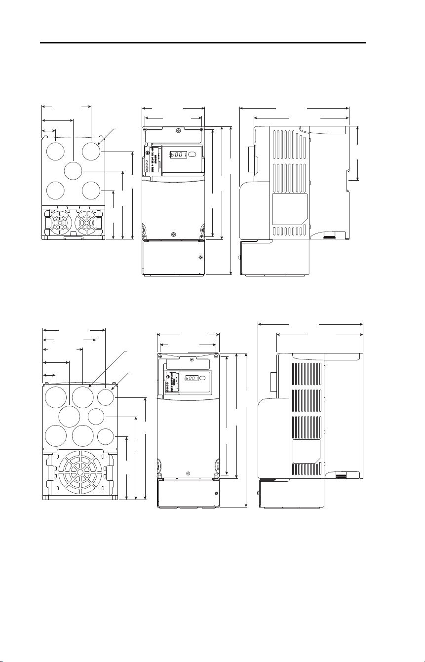
138 Rockwell Automation Publication 22D-UM001F-EN-E - September 2024
Appendix B Accessories and Dimensions
Figure 10 – IP 30/NEMA 1/UL Type 1 Option Kit with Communication Option
180
(7.09)
244
(9.61)
168
(6.61)
100.0 (3.94)
87.0 (3.43) 136.0 (5.35)
161.0 (6.34)
∅
22.2
(0.87)
RUN
REV
FAULT
RUN
REV
FAULT
87.4
(3.44)
76.3
(3.00)
105.3
(4.15)
134.3
(5.29)
50.0 (1.97)
77.5 (3.05)
22.5 (0.89)
260
(10.2)
320
(12.6)
246
(9.7)
130.0 (5.1)
116.0 (4.57)
180.0 (7.1)
205.0 (8.07)
RUN
REV
FAULT
45.7 (1.80)
109.8
(4.32)
144.8
(5.70)
179.8
(7.08)
69.2 (2.72)
92.2 (3.63)
108.7 (4.28)
22.2 (0.87)
∅
22.2
(0.87)
∅
28.5
(1.12)
Frame B - 22-JBCB
Frame C - 22-JBCC
Dimensions are in millimeters and (inches)
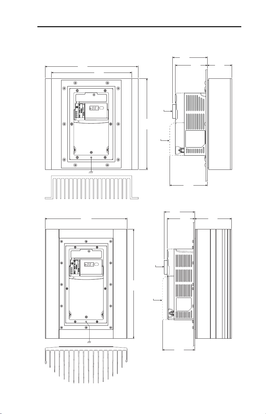
Rockwell Automation Publication 22D-UM001F-EN-E - September 2024 139
Appendix B Accessories and Dimensions
Figure 11 – PowerFlex 40P Flange Mount Drives
244
(9.61)
250
(9.84)
94.3
(3.71)
63.1
(2.48)
214
(8.43)
106.3
(4.19)
RUN
REV
FAULT
RUN
REV
FAULT
20A-DG01
119.3
(4.70)
22D-CCB
138.2
(5.44)
105.8
(4.17)
325
(12.8)
300
(11.81)
117.8
(4.64)
130.3
(5.13)
RUN
REV
FAULT
RUN
REV
FAULT
20A-DG01
22D-CCC
Frame B
Frame C
Dimensions are in millimeters and (inches)
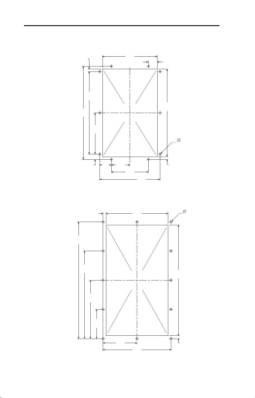
140 Rockwell Automation Publication 22D-UM001F-EN-E - September 2024
Appendix B Accessories and Dimensions
Figure 12 – PowerFlex 40P Flange Mount Cutout Dimensions
210
(8.27)
98
(3.86)
160
(6.30)
145
(5.71)
49
(1.93)
31
(1.22)
7.5
(0.30)
14
(0.55)
98.5
(3.88)
197
(7.76)
6.5
(0.26)
225
(8.86)
23.5
(0.93)
5.3
(0.21)
291.5
(11.48)
164
(6.46)
180
(7.09)
90
(3.54)
307.5
(12.11)
230.6
(9.08)
153.8
(6.06)
76.9
(3.03)
8
(0.31)
8
(0.31)
5.3
(0.21)
Frame B
Frame C
Dimensions are in millimeters and (inches)
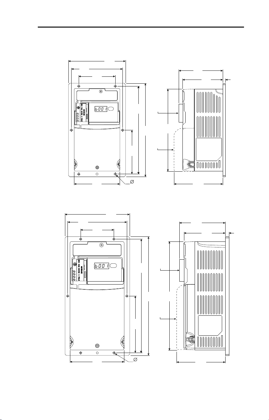
Rockwell Automation Publication 22D-UM001F-EN-E - September 2024 141
Appendix B Accessories and Dimensions
Figure 13 – PowerFlex 40P Plate Drive Dimensions
125
(4.92)
204
(8.03)
180
(7.09)
192
(7.56)
96
(3.78)
9.5
(0.37)
88
(3.46)
100
(3.94)
112
(4.41)
100
(3.94)
80
(3.15)
5.3
(0.21)
RUN
REV
FAULT
RUN
REV
FAULT
20A-DG01
113
(4.45)
22D-CCB
155
(6.10)
284
(11.18)
260
(10.24)
272
(10.71)
136
(5.35)
9.5
(0.37)
98.5
(3.88)
110.5
(4.35)
123.5
(4.86)
142
(5.59)
130
(5.12)
80
(3.15)
5.3
(0.21)
RUN
REV
FAULT
RUN
REV
FAULT
20A-DG01
22D-CCC
Frame B
Frame C
Dimensions are in millimeters and (inches)
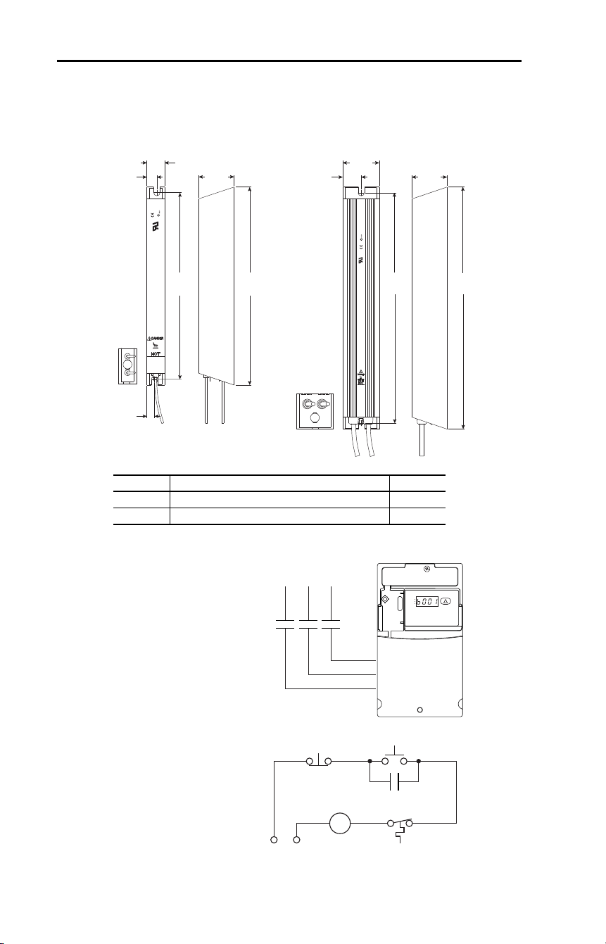
142 Rockwell Automation Publication 22D-UM001F-EN-E - September 2024
Appendix B Accessories and Dimensions
Figure 14 – Dynamic Brake Modules
Figure 15 – Recommended External Brake Resistor Circuitry
Frame Catalog Number Weight
A AK-R2-091P500, AK-R2-047P500, AK-R2-360P500 1.1 (2.5)
B AK-R2-030P1K2, AK-R2-120P1K2 2.7 (6)
335.0
(13.19)
60.0
(2.36)
30.0
(1.18)
17.0
(0.67)
59.0
(2.32)
13.0
(0.51)
405.0
(15.94)
386.0
(15.20)
316.0
(12.44)
61.0
(2.40)
31.0
(1.22)
ROCKWELL
AUTOMATION
CUS
SURFACES MAY BE
ROCKWELL
AUTOMATION
CUS
Frame A Frame B
Dimensions are in millimeters and (inches). Weights are in kilograms and (pounds).
Po w er On
R (L1)
S (L2)
T (L3)
Po w er So urce DB r esist or ther mosta t
Po w er O
M
M
(Input contactor) M
3-phase
AC Input
RUN
REV
FAU LT
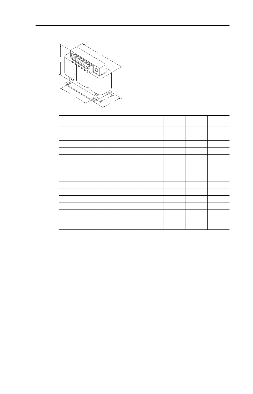
Rockwell Automation Publication 22D-UM001F-EN-E - September 2024 143
Appendix B Accessories and Dimensions
Figure 16 – Bulletin 1321-3R Series Line Reactors
Catalog Number
A
mm (in.)
B
mm (in.)
C
mm (in.)
D
mm (in.)
E
mm (in.)
Weight
kg (lbs)
1321-3R2-A 112 (4.40) 104 (4.10) 70 (2.75) 50 (1.98) 37 (1.44) 1.8 (4)
1321-3R2-B 112 (4.40) 104 (4.10) 70 (2.75) 50 (1.98) 37 (1.44) 1.8 (4)
1321-3R4-A 112 (4.40) 104 (4.10) 76 (3.00) 50 (1.98) 37 (1.44) 1.8 (4)
1321-3R4-B 112 (4.40) 104 (4.10) 76 (3.00) 50 (1.98) 37 (1.44) 1.8 (4)
1321-3R4-C 112 (4.40) 104 (4.10) 86 (3.38) 60 (2.35) 37 (1.44) 2.3 (5)
1321-3R4-D 112 (4.40) 104 (4.10) 92 (3.62) 66 (2.60) 37 (1.44) 2.7 (6)
1321-3R8-A 152 (6.00) 127 (5.00) 76 (3.00) 53 (2.10) 51 (2.00) 3.1 (7)
1321-3R8-B 152 (6.00) 127 (5.00) 76 (3.00) 53 (2.10) 51 (2.00) 3.6 (8)
1321-3R8-C 152 (6.00) 127 (5.00) 85 (3.35) 63 (2.48) 51 (2.00) 4.9 (11)
1321-3R12-A 152 (6.00) 127 (5.00) 76 (3.00) 53 (2.10) 51 (2.00) 4.1 (9)
1321-3R12-B 152 (6.00) 127 (5.00) 76 (3.00) 53 (2.10) 51 (2.00) 4.5 (10)
1321-3R18-A 152 (6.00) 133 (5.25) 79 (3.10) 54 (2.13) 51 (2.00) 4.1 (9)
1321-3R18-B 152 (6.00) 133 (5.25) 86 (3.40) 63 (2.48) 51 (2.00) 5.4 (12)
1321-3R25-A 183 (7.20) 146 (5.76) 85 (3.35) 60 (2.35) 76 (3.00) 4.9 (11)
1321-3R35-A 193 (7.60) 146 (5.76) 91 (3.60) 66 (2.60) 76 (3.00) 6.3 (14)
D
C
B
A
E
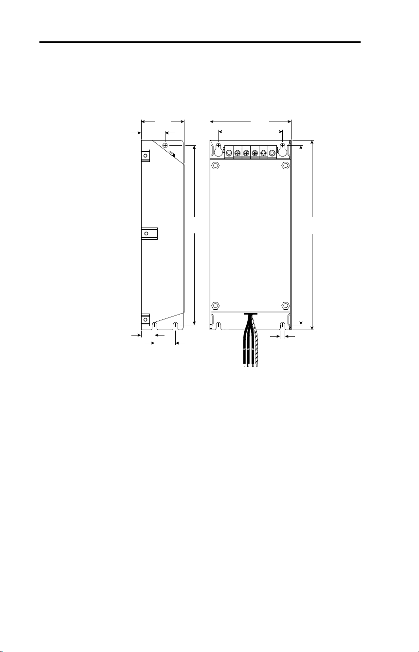
144 Rockwell Automation Publication 22D-UM001F-EN-E - September 2024
Appendix B Accessories and Dimensions
Figure 17 – Frame B EMC Line Filters
5.5 (0.22)
17.8
(0.70)
24.0
(0.94)
78
(3.07)
100
(3.94)
50
(1.97)
29.8
(1.17)
229
(9.02)
216
(8.50)
217
(8.54)
Dimensions are in millimeters and (inches).
Catalog Numbers: 22-RF0P8-BL; 22-RF012-BS, 22-RF012-BL (Series B);
22-RF021-BS, 22-RF021-BL
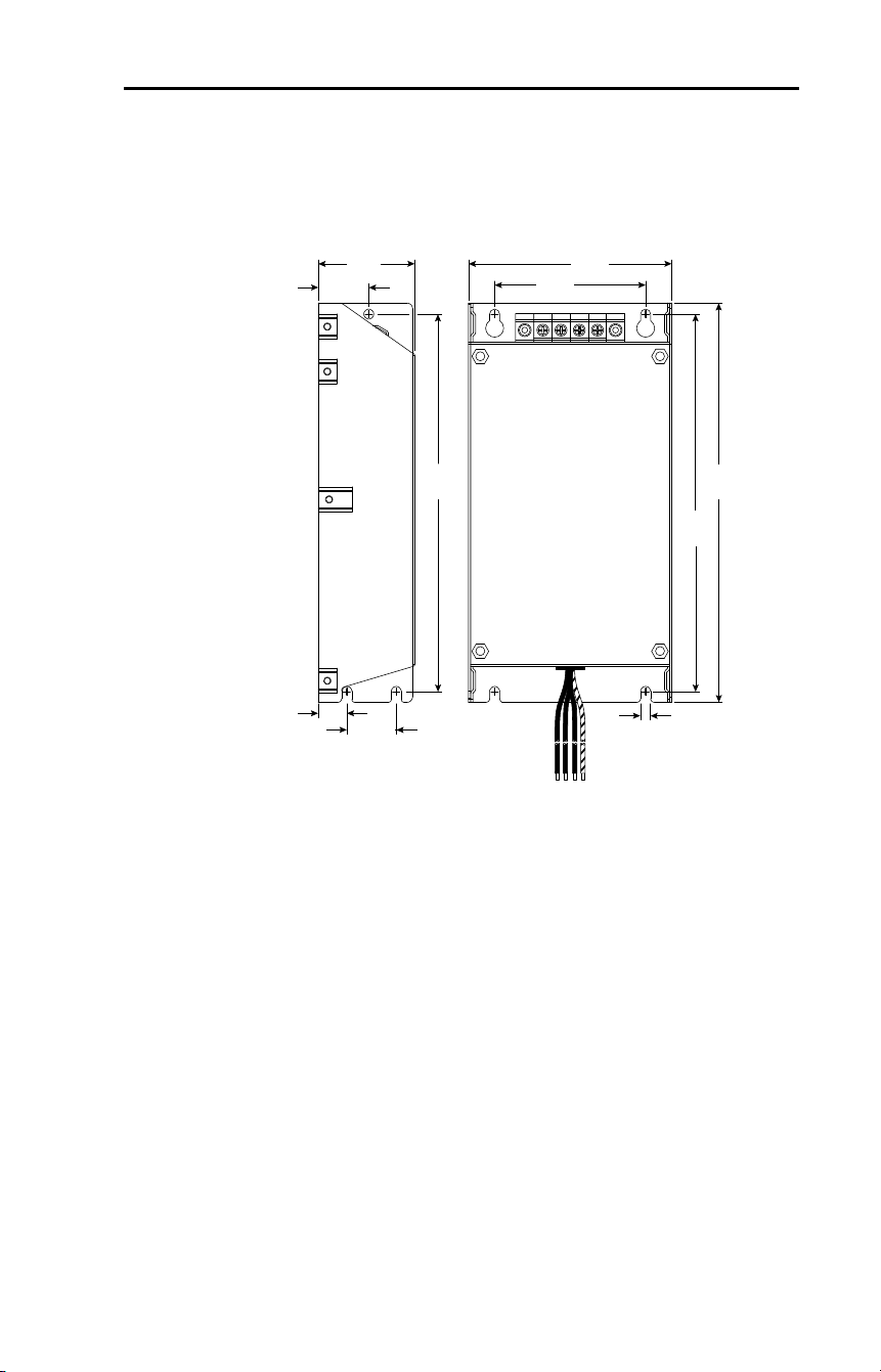
Rockwell Automation Publication 22D-UM001F-EN-E - September 2024 145
Appendix B Accessories and Dimensions
Figure 18 – Frame C EMC Line Filters
5.5 (0.22)
17
(0.67)
30
(1.18)
90
(3.54)
130
(5.12)
60
(2.36)
32
(1.26)
309
(12.17)
297
(11.69)
297
(11.69)
Dimensions are in millimeters and (inches).
Catalog Numbers: 22-RF018-CS, 22-RF018-CL; 22-RF025-CL; 22-RF026-CS,
22-RF026-CL; 22-RF034-CS, 22-RF034-CL
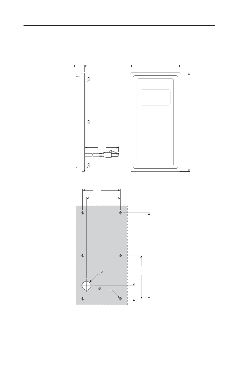
146 Rockwell Automation Publication 22D-UM001F-EN-E - September 2024
Appendix B Accessories and Dimensions
Figure 19 – Remote (Panel Mount) HIM
93
(3.66)
25
(0.98)
2m
180
(7.09)
154
(6.06)
77
(3.03)
23.5
(0.93)
67
(2.64)
60
(2.36)
19.1
(0.75)
4.8
(0.19)
Dimensions are in millimeters and (inches).
Catalog Number: 22-HIM-C2S
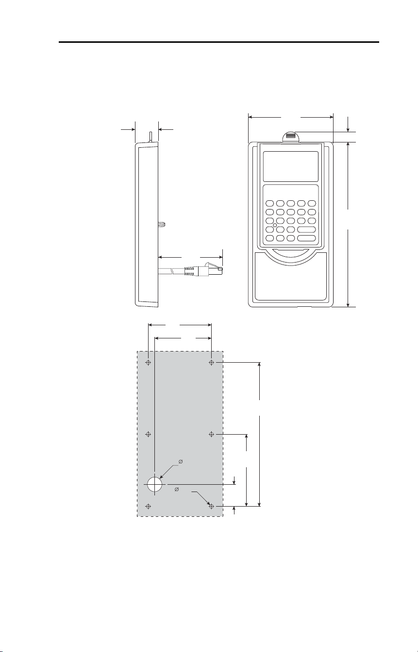
Rockwell Automation Publication 22D-UM001F-EN-E - September 2024 147
Appendix B Accessories and Dimensions
Figure 20 – NEMA Type 1 Bezel
93
(3.66)
25.2
(0.99)
2m
180
(7.09)
11.1
(0.44)
154
(6.06)
77
(3.03)
23.5
(0.93)
67
(2.64)
60
(2.36)
19.1
(0.75)
4.8
(0.19)
Dimensions are in millimeters and (inches).
Catalog Number: 22-HIM-B1

148 Rockwell Automation Publication 22D-UM001F-EN-E - September 2024
Appendix B Accessories and Dimensions
Notes:
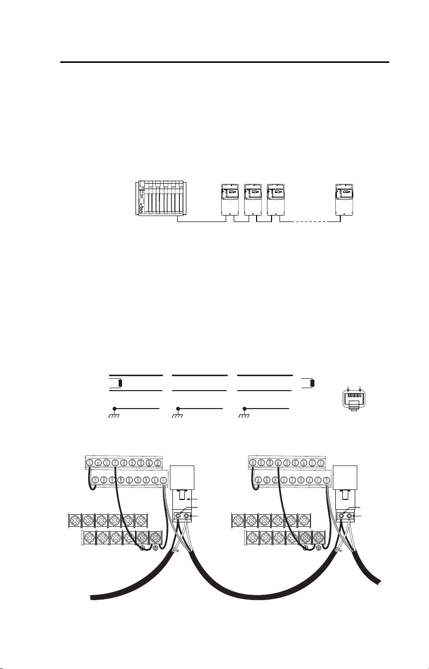
Rockwell Automation Publication 22D-UM001F-EN-E - September 2024 149
Appendix C
RS-485 (DSI) Protocol
PowerFlex 40P drives support the RS-485 (DSI) protocol to allow
efficient operation with Rockwell Automation peripherals. In addition,
some Modbus functions are supported to allow simple networking.
PowerFlex 40P drives can be multi-dropped on an RS-485 network using
Modbus protocol in RTU mode.
For information regarding DeviceNet or other communication protocols,
see the appropriate user manual.
Network Wiring
Network wiring consists of a shielded 2-conductor cable that is
daisy-chained from node to node.
Figure 21 – Network Wiring Diagram
Controller
Master
PowerFlex 40P
Node 1
5
4
PowerFlex 40P
Node 2
5
4
PowerFlex 40P
Node "n "
5
4
TxRx D -
TxRx D +
TxRx D -
TxRx D +
TxRx D -
TxRx D +
NOTE: The shield is connected at ONLY ONE end of each cable segm ent.
Shield Shield Shield
120
Ω
resist o r
120
Ω
resist o r
X X X
FRON T
PIN 8
PIN 1
TxRxD +
TxRxD -
V/ T2T/ L3S/ L2R/ L1 U / T1
W/T 3
BR+ BR-DC- DC+
01 02 03 04 05
11 12 13 14 15
06 07 08 09
16 17 18 19
RS-485
(DPI)
AK-00-RJ45-TB2P
V/T 2T/ L3S/L2R/L1 U/ T1 W/T3
BR+ BR-DC- DC+
01 02 03 04 05
11 12 13 14 15
06 07 08 09
16 17 18 19
RS-485
(DPI)
TxRxD +
TxRxD -

150 Rockwell Automation Publication 22D-UM001F-EN-E - September 2024
Appendix C RS-485 (DSI) Protocol
Only pins 4 and 5 on the RJ45 plug should be wired. The other pins on
the PowerFlex 40P RJ45 socket must not be connected because they
contain power, and so on. for other Rockwell Automation peripheral
devices.
Wiring terminations on the master controller will vary depending on the
master controller used and “TxRxD+” and “TxRxD-” are shown for
illustration purposes only. See the master controller’s user manual for
network terminations. Note that there is no standard for the “+” and “-”
wires, and consequently Modbus device manufacturers interpret them
differently. If you have problems with initially establishing
communications, try swapping the two network wires at the master
controller.
Standard RS-485 wiring practices apply.
• Termination resistors need to be applied at each end of the network
cable.
• RS-485 repeaters may need to be used for long cable runs, or if
greater than 32 nodes are needed on the network.
• Network wiring should be separated from power wires by at least
0.3 m (1 ft).
• Network wiring should only cross power wires at a right angle.
I/O Terminal 19 (DSI Shield) on the PowerFlex 40P drive must also be
connected to PE ground (there are two PE terminals on the drive). See
Table 10
for more information.
Network Common is internally tied to I/O Terminal 04 (Digital
Common). Tying I/O Terminal 04 to PE ground may improve noise
immunity in some applications.

Rockwell Automation Publication 22D-UM001F-EN-E - September 2024 151
Appendix C RS-485 (DSI) Protocol
Parameter Configuration
The following PowerFlex 40P drive parameters are used to configure the
drive to operate on a network.
Supported Modbus Function Codes
The peripheral interface (DSI) used on PowerFlex 40P drives supports
some of the Modbus function codes.
Important: Modbus devices can be 0-based (registers are numbered
starting at 0) or 1-based (registers are numbered starting at
1). Depending on the Modbus Master used, the register
addresses listed on the following pages may need to be
offset by +1. For example, Logic Command may be register
address 8192 for some master devices (for example,
ProSoft 3150-MCM SLC™ Modbus scanner) and 8193 for
others (for example, PanelView™).
Parameter Details Reference
P036 [Start Source] Set to 5 “Comm Port” if Start is controlled from the
network.
Page 56
P038 [Speed Reference] Set to 5 “Comm Port” if the Speed Reference is
controlled from the network.
Page 58
A103 [Comm Data Rate] Sets the data rate for the RS-485 (DSI) Port. All nodes
on the network must be set to the same data rate.
Page 80
A104 [Comm Node Addr] Sets the node address for the drive on the network.
Each device on the network requires a unique node
address.
Page 80
A105 [Comm Loss Action] Selects the drive’s response to communication
problems.
Page 80
A106 [Comm Loss Time] Sets the time that the drive will remain in
communication loss before the drive implements A105
[Comm Loss Action].
Page 80
A107 [Comm Format] Sets the transmission mode, data bits, parity and stop
bits for the RS-485 (DSI) Port. All nodes on the network
must be set to the same setting.
Page 81
E207 [Comm Write Mode] Set to 0 “EEPROM” when programming drive.
Set to 1 “RAM only” to only write to volatile memory.
Page 98
Modbus Function Code (Decimal) Command
03 Read Holding Registers
06 Preset (Write) Single Register
16 (10 Hexadecimal) Preset (Write) Multiple Registers

152 Rockwell Automation Publication 22D-UM001F-EN-E - September 2024
Appendix C RS-485 (DSI) Protocol
Writing (06) Logic Command Data
The PowerFlex 40P drive can be controlled via the network by sending
Function Code 06 writes to register address 8192 (Logic Command).
P036
[Start Source] must be set to 5 “Comm Port” in order to accept the
commands. Parameter E249 [Cmd Stat Select] is used to select Velocity
or Position Bit definitions.
Velocity Bit Definitions
Logic Command - E249 = 0 “Velocity”
Address (Decimal) Bit(s) Description
8192
0 1 = Stop, 0 = Not Stop
1 1 = Start, 0 = Not Start
2 1 = Jog, 0 = No Jog
3 1 = Clear Faults, 0 = Not Clear Faults
5,4
00 = No Command
01 = Forward Command
10 = Reverse Command
11 = No Command
6 1 = Logic In 1
7 1 = Logic In 2
9,8
00 = No Command
01 = Accel Rate 1
10 = Accel Rate 2
11 = Hold Accel Rate Selected
11,10
00 = No Command
01 = Decel Rate 1
10 = Decel Rate 2
11 = Hold Decel Rate Selected
14,13,12
000 = No Command
001 = Freq. Source = P036 [Start Source]
010 = Freq. Source = A069 [Internal Freq]
011 = Freq. Source = Comms (Addr 8193)
100 = A070 [Preset Freq 0]
101 = A071 [Preset Freq 1]
110 = A072 [Preset Freq 2]
111 = A073 [Preset Freq 3]
15 Not Used

Rockwell Automation Publication 22D-UM001F-EN-E - September 2024 153
Appendix C RS-485 (DSI) Protocol
Position Bit Definitions
Writing (06) Reference
The Speed Reference to a PowerFlex 40P drive can be controlled via the
network by sending Function Code 06 writes to register address 8193
(Reference). P038 [Speed Reference] must be set to 5 “Comm Port” in
order to accept the Speed Reference.
Logic Command - E249 = 1 “Position”
Address (Decimal) Bit(s) Description
8192
0 1 = Stop, 0 = Not Stop
1 1 = Start, 0 = Not Start
2 1 = Jog, 0 = No Jog
3 1 = Clear Faults, 0 = Not Clear Faults
5,4
00 = No Command
01 = Forward Command
10 = Reverse Command
11 = No Command
6 1 = Logic In 1
7 1 = Logic In 2
10,9,8
000 = A070 Freq. Source, E230 Position Source
001 = A071 Freq. Source, E232 Position Source
010 = A072 Freq. Source, E234 Position Source
011 = A073 Freq. Source, E236 Position Source
100 = A074 Freq. Source, E238 Position Source
101 = A075 Freq. Source, E240 Position Sourcec
110 = A076 Freq. Source, E242 Position Source
111 = A077 Freq. Source, E244 Position Source
11 1 = Find Home
12 1 = Hold Step
13 1 = Pos Redefine
14 1 = Sync Enable
15 1 = Traverse Disable
Reference
Address (Decimal) Description
8193
A decimal value entered as xxx.xx where the decimal point is fixed. For
example, a decimal “100” equals 1.00 Hz and “543” equals 5.43 Hz.

154 Rockwell Automation Publication 22D-UM001F-EN-E - September 2024
Appendix C RS-485 (DSI) Protocol
Reading (03) Logic Status Data
The PowerFlex 40P Logic Status data can be read via the network by
sending Function Code 03 reads to register address 8448 (Logic Status).
Parameter E249
[Cmd Stat Select] is used to select Velocity or Position
Bit definitions.
Velocity Bit Definitions
Position Bit Definitions
Logic Status - E249 = 0 “Velocity”
Address (Decimal) Bit(s) Description
8448
0 1 = Ready, 0 = Not Ready
1 1 = Active (Running), 0 = Not Active
2 1 = Cmd Forward, 0 = Cmd Reverse
3 1 = Rotating Forward, 0 = Rotating Reverse
4 1 = Accelerating, 0 = Not Accelerating
5 1 = Decelerating, 0 = Not Decelerating
6 Not Used
7 1 = Faulted, 0 = Not Faulted
8 1 = At Reference, 0 = Not At Reference
9 1 = Reference Controlled by Comm
10 1 = Operation Cmd Controlled by Comm
11 1 = Parameters have been locked
12 Digital Input 1 Status
13 Digital Input 2 Status
14 Digital Input 3 Status
15 Digital Input 4 Status
Logic Status - E249 = 1 “Position”
Address (Decimal) Bit(s) Description
8448
0 1 = Ready, 0 = Not Ready
1 1 = Active (Running), 0 = Not Active
2 1 = Cmd Forward, 0 = Cmd Reverse
3 1 = Rotating Forward, 0 = Rotating Reverse
4 1 = Accelerating, 0 = Not Accelerating
5 1 = Decelerating, 0 = Not Decelerating
6 1 = Forward Travel Position, 0 = Reverse Travel Position
7 1 = Faulted, 0 = Not Faulted
8 1 = At Speed, 0 = Not At Speed
9 1 = At Position, 0 = Not At Position
10 1 = At Home, 0 = Not At Home
11 1 = Drive Homed, 0 = Not Drive Homed
12 1 = Sync Hold, 0 = Not Syc Hold
13 1 = Sync Ramp, 0 = Not Syc Ramp
14 1 =Traverse On, 0 = Traverse Off
15 1 = Traverse Decel, 0 = Not Trav Decel

Rockwell Automation Publication 22D-UM001F-EN-E - September 2024 155
Appendix C RS-485 (DSI) Protocol
Reading (03) Feedback
The Feedback (Output Frequency) from the PowerFlex 40P drive can be
read via the network by sending Function Code 03 reads to register
address 8451 (Feedback).
Reading (03) Drive Error Codes
The PowerFlex 40P Error Code data can be read via the network by
sending Function Code 03 reads to register address 8449 (Drive Error
Codes).
Feedback
(1)
Address (Decimal) Description
8451
A xxx.x decimal value where the decimal point is fixed. For example, a decimal
“123” equals 12.3 Hz and “300” equals 30.0 Hz.
(1)
Returns the same data as Reading (03) Parameter d001 [Output Freq].
Logic Status
Address (Decimal) Value (Decimal) Description
8449
0 No Fault
2 Auxiliary Input
3 Power Loss
4 Undervoltage
5 Overvoltage
6 Motor Stalled
7 Motor Overload
8 Heatsink Overtemperature
12 HW Overcurrent (300%)
13 Ground Fault
29 Analog Input Loss
33 Auto Restart Tries
38 Phase U to Ground Short
39 Phase V to Ground Short
40 Phase W to Ground Short
41 Phase UV Short
42 Phase UW Short
43 Phase VW Short
48 Parameters Defaulted
63 Software Overcurrent
64 Drive Overload
70 Power Unit Fail
71 Network Loss Fault
80 AutoTune Fail
81 Communication Loss
94 Encoder Loss Fault
100 Parameter Checksum Error
111 Hardware Enable Fault
122 I/O Board Fail

156 Rockwell Automation Publication 22D-UM001F-EN-E - September 2024
Appendix C RS-485 (DSI) Protocol
Reading (03) and Writing (06) Drive Parameters
To access drive parameters, the Modbus register address equals the
parameter number. For example, a decimal “1” is used to address
Parameter d001 [Output Freq] and decimal “39” is used to address
Parameter P039
[Accel Time 1].
Additional Information
Go to https://www.ab.com/drives/ for additional information.

Rockwell Automation Publication 22D-UM001F-EN-E - September 2024 157
Appendix D
RJ45 DSI Splitter Cable
The PowerFlex 40P drive provides a RJ45 port to allow the connection
of a single peripheral device. The RJ45 DSI splitter cable can be used to
connect a second DSI peripheral device to the drive.
Connectivity Guidelines
• Two peripherals maximum can be attached to a drive.
• If a single peripheral is used, it must be connected to the Master port
(M) on the splitter and configured for “Auto” (default) or “Master.”
Parameter 9 [Device Type] on the DSI / MDI keypads and Parameter
1 [Adapter Cfg] on the Serial Converter are used to select the type
(Auto / Master / Slave).
• Do not use the RJ45 splitter cable with a drive that has an
internal network communication adapter installed. Since only
one additional peripheral can be added, the second peripheral can be
connected directly to the RJ45 port on the drive. The internal Comm
is always the Master, therefore the external peripheral must be
configured as “Auto” (for temporary connections) or “Slave” (for
permanent connections).
• If two peripherals will be powered up at the same time, one must be
configured as the “Master” and connected to the Master port (M) and
the other must be connected as the “Slave” and connected to the
Slave port (S).
!
ATTENTION: Risk of injury or equipment damage exists. The
peripherals may not perform as intended if these Connectivity
Guidelines are not followed. Precautions should be taken to follow
these Connectivity Guidelines.
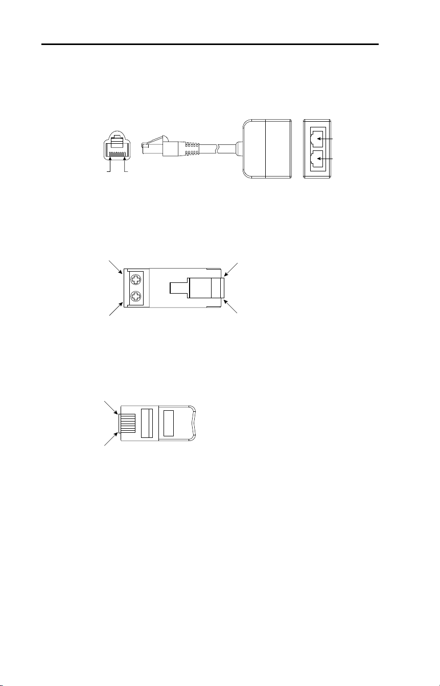
158 Rockwell Automation Publication 22D-UM001F-EN-E - September 2024
Appendix D RJ45 DSI Splitter Cable
DSI Cable Accessories
RJ45 Splitter Cable – Catalog Number: AK-U0-RJ45-SC1
RJ45 Two-Position Terminal Block Adapter –
Catalog Number: AK-U0-RJ45-TB2P
RJ45 Adapter with Integrated Termination Resistor –
Catalog Number: AK-U0-RJ45-TR1
Slave Port
Master Port
PIN
8
PIN 1
M
S
TB2
(PIN 5)
TB1
(PIN 4)
PIN 8
PIN 1
PIN 8
PIN 1
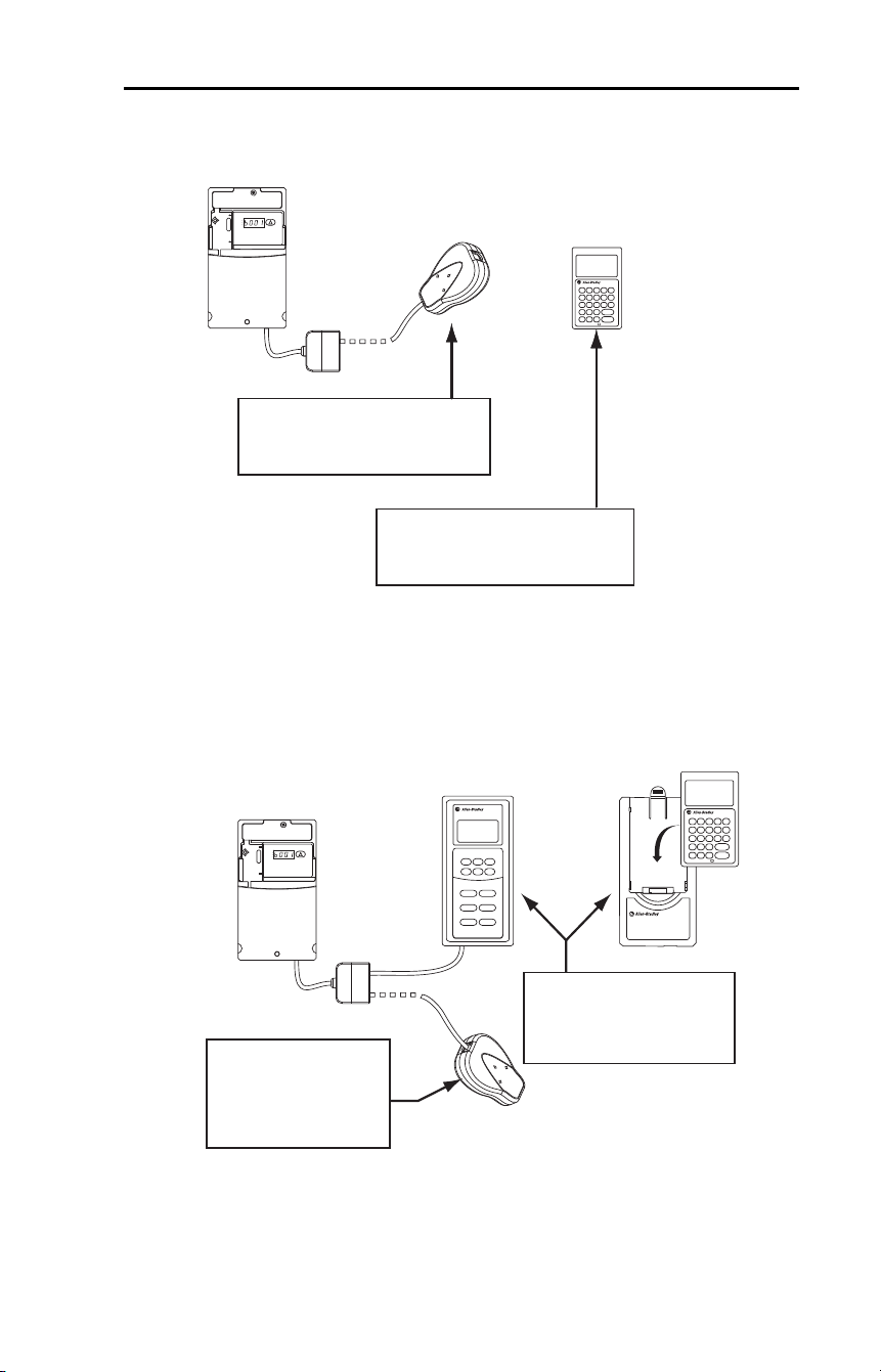
Rockwell Automation Publication 22D-UM001F-EN-E - September 2024 159
Appendix D RJ45 DSI Splitter Cable
Connecting One Temporary Peripheral
Connecting One Temporary Peripheral and
One Permanent Peripheral
M
S
Serial Converter
Parameter 1 [Adapter Cfg] set to "Auto"
(default) or "Master" and connected to
Master port (M) on RJ45 Splitter Cable
DSI
DSI / MDI
Hand Held
or
Parameter 9 [Device Type] set to "Auto"
(default) or "Master" and connected to
Master port (M) on RJ45 Splitter Cable
DSI / MDI Drive
Serial converter
NEMA 4
Panel mount unit
or
NEMA 1 Bezel
with DSI / MDI hand held
Parameter 9 [Device Type]
set to "Master" and
connected to Master port (M)
on RJ45 splitter cable
Parameter 1 [Adapter Cfg]
set to "Auto" (default) or
"Slave" and connected to
Slave port (S)
on RJ45 splitter cable
DSI
M
S
DSI/MDI Drive
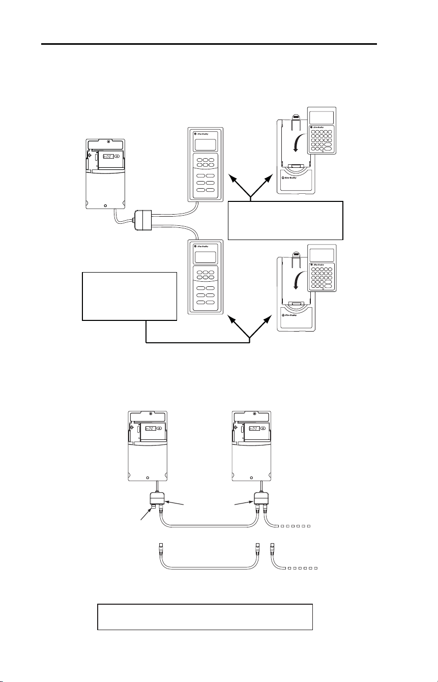
160 Rockwell Automation Publication 22D-UM001F-EN-E - September 2024
Appendix D RJ45 DSI Splitter Cable
Connecting Two Permanent Peripherals
Connecting an RS-485 Network
or
NEMA 1 Bezel
with DSI/MDI hand held
NEMA 4
Panel mount unit
Parameter 9 [Device Type] set to
"Master" and connected to Master
port (M) on RJ45 splitter cable
Parameter 9 [Device Type]
set to "Slave" and
connected to Slave port (S)
on RJ45 splitter cable
M
S
DSI/MDI Drive
or
AK-U0-RJ45-TR1
Terminating resistor
(end of network)
AK-U0-RJ45-TB2P
Two-position
terminal block
DSI/MDI Drives
or
or
Customer supplied RJ45 male-to-RJ45 male
cables with wires connected at pins 4 and 5 only.
Both the Master (M) and Slave (S) ports on the RJ45 splitter
cable operate as standard RS-485 ports in this con guration.

Rockwell Automation Publication 22D-UM001F-EN-E - September 2024 161
Appendix E
Velocity StepLogic, Basic Logic and
Timer/Counter Functions
Four PowerFlex 40P logic functions provide the capability to program
simple logic functions without a separate controller.
• Velocity StepLogic Function
Steps through up to eight preset speeds based on programmed logic.
Programmed logic can include conditions that need to be met from
digital inputs programmed as “Logic In1” and “Logic In2” before
stepping from one preset speed to the next. A timer is available for
each of the eight steps and is used to program a time delay before
stepping from one preset speed to the next. The status of a digital
output can also be controlled based on the step being executed.
• Basic Logic Function
Up to two digital inputs can be programmed as “Logic In1” and/or
“Logic In2”. A digital output can be programmed to change state
based on the condition of one or both inputs based on basic logic
functions such as AND, OR, NOR. The basic logic functions can be
used with or without StepLogic.
• Timer Function
A digital input can be programmed for “Timer Start”. A digital
output can be programmed as a “Timer Out” with an output level
programmed to the desired time. When the timer reaches the time
programmed into the output level the output will change state. The
timer can be reset via a digital input programmed as “Reset Timer”.
• Counter Function
A digital input can be programmed for “Counter In”. A digital output
can be programmed as “Counter Out” with an output level
programmed to the desired number of counts. When the counter
reaches the count programmed into the output level the output will
change state. The counter can be reset via a digital input
programmed as “Reset Counter”.
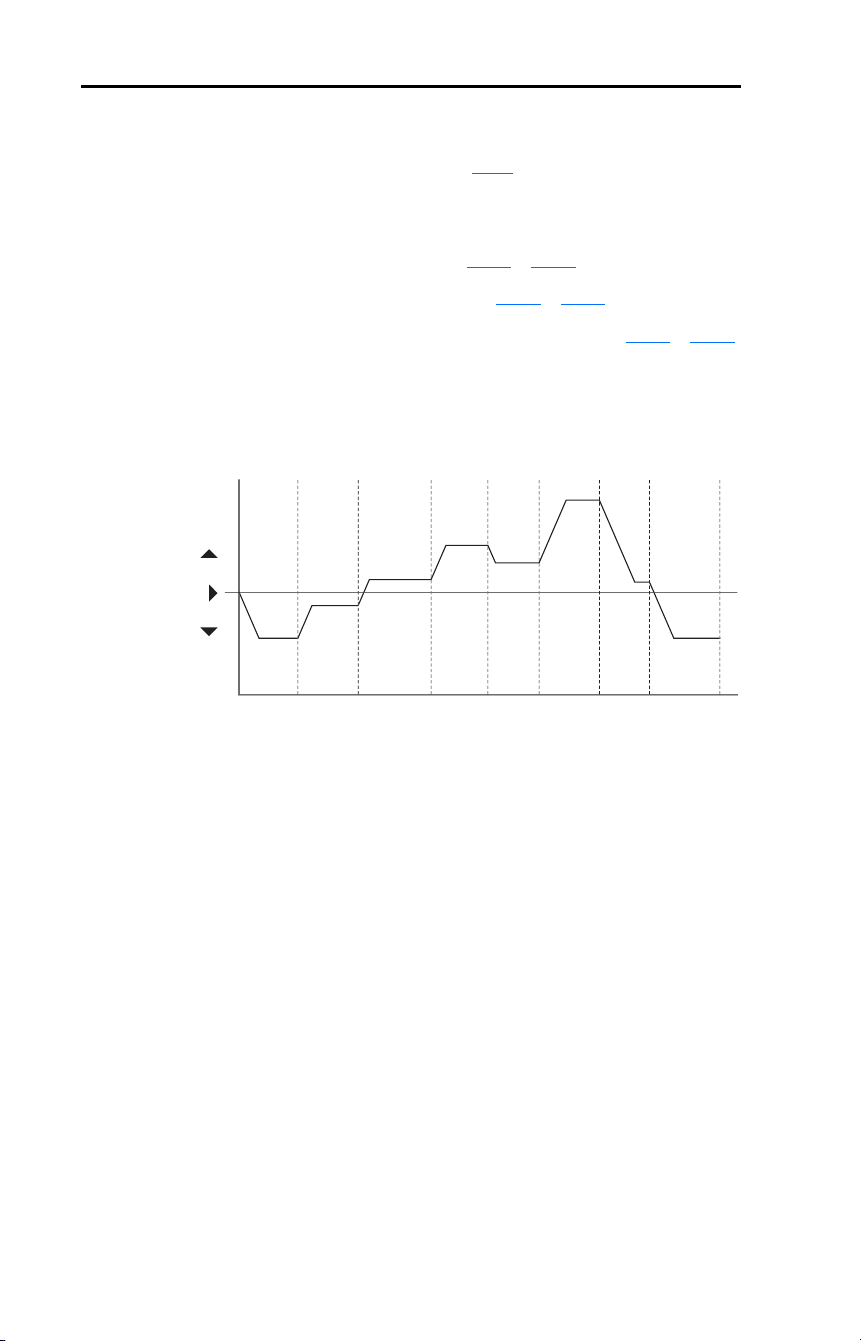
162 Rockwell Automation Publication 22D-UM001F-EN-E - September 2024
Appendix E Velocity StepLogic, Basic Logic and Timer/Counter Functions
Velocity StepLogic Using Timed Steps
To activate this function, set parameter P038 [Speed Reference] to 6 “Stp
Logic”. Three parameters are used to configure the logic, speed
reference and time for each step.
• Logic is defined using parameters A140
…A147 [Stp Logic x].
• Preset Speeds are set with parameters A070
…A077 [Preset Freq x].
• Time of operation for each step is set with parameters A150
…A157
[Stp Logic Time x].
The direction of motor rotation can be forward or reverse.
Figure 22 – Using Timed Steps
Velocity StepLogic Sequence
• Sequence begins with a valid start command.
• A normal sequence begins with Step 0 and transition to the next step
when the corresponding StepLogic time has expired.
• Step 7 is followed by Step 0
• Sequence repeats until a stop is issued or a fault condition occurs.
Ti
m
e
0
Forw
a
r
d
R
e
v
e
r
se
Ste
p
0
Ste
p
1
Ste
p
2
Ste
p
3
Ste
p
4
Ste
p
5
Ste
p
6
Ste
p
7
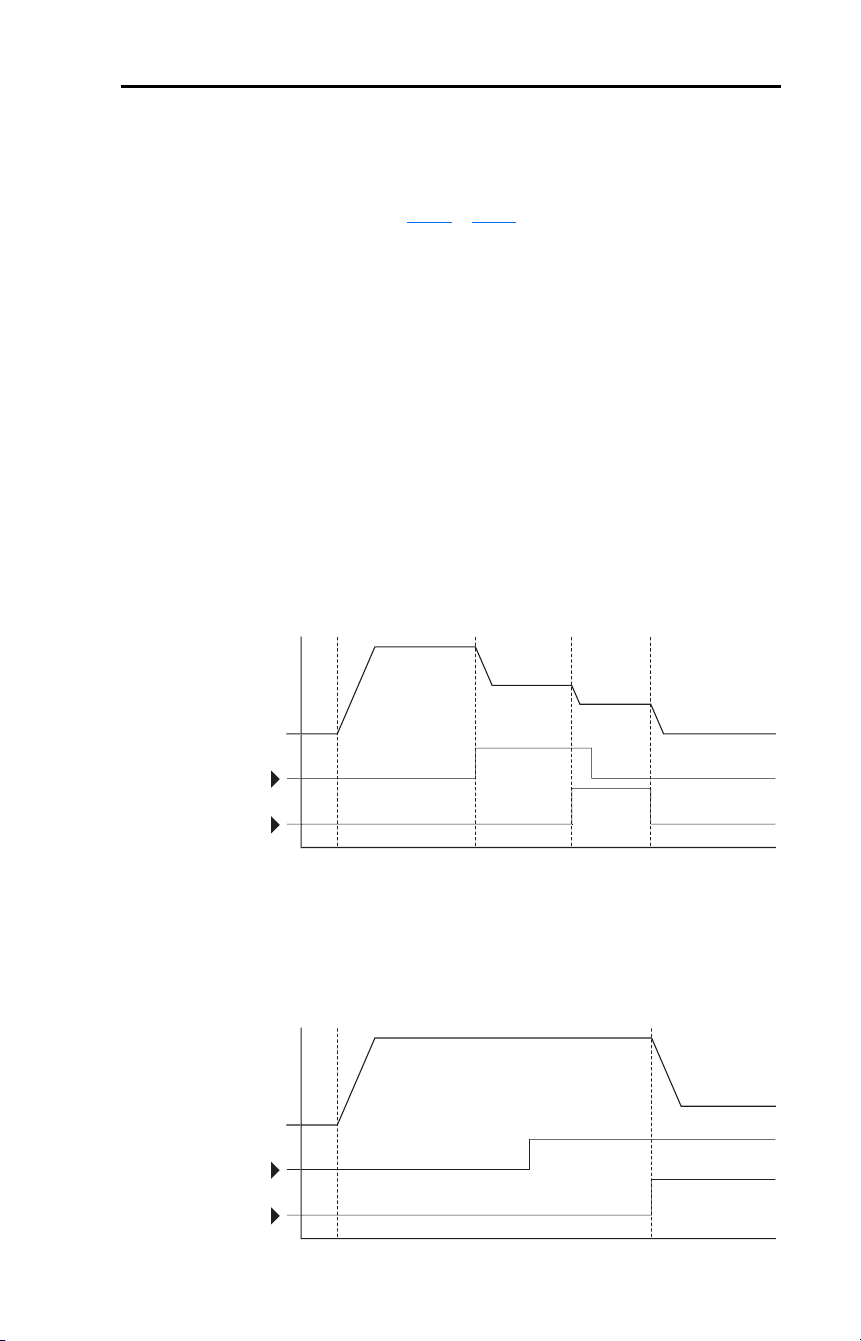
Rockwell Automation Publication 22D-UM001F-EN-E - September 2024 163
Appendix E Velocity StepLogic, Basic Logic and Timer/Counter Functions
Velocity StepLogic Using Basic Logic Functions
Digital input and digital output parameters can be configured to use logic
to transition to the next step. Logic In1 and Logic In2 are defined by
programming parameters A051
…A054 [Digital Inx Sel] to option 23
“Logic In1” or option 24 “Logic In2”.
Example
• Run at Step 0.
• Transition to Step 1 when Logic In1 is true.
Logic senses the edge of Logic In1 when it transitions from off to on.
Logic In1 is not required to remain “on”.
• Transition to Step 2 when both Logic In1 and Logic In2 are true.
The drive senses the level of both Logic In1 and Logic In2 and
transitions to Step 2 when both are on.
• Transition to Step 3 when Logic In2 returns to a false or off state.
Inputs are not required to remain in the “on” condition except under
the logic conditions used for the transition from Step 2 to Step 3.
The step time value and the basic logic may be used together to satisfy
machine conditions. For instance, the step may need to run for a
minimum time period and then use the basic logic to trigger a transition
to the next step.
Ti
m
e
Lo
g
ic In
1
Lo
g
ic In
2
Frequenc
y
S
tar
t
Ste
p
0
Ste
p
1
Ste
p
2
Ste
p
3
Tim
e
Lo
g
ic In
1
Lo
g
ic In
2
Frequenc
y
S
tar
t
Ste
p
0
Ste
p
1

164 Rockwell Automation Publication 22D-UM001F-EN-E - September 2024
Appendix E Velocity StepLogic, Basic Logic and Timer/Counter Functions
Timer Function
Digital inputs and outputs control the timer function and are configured
with parameters A051
…A054 [Digital Inx Sel] set to 18 “Timer Start”
and 20 “Reset Timer”.
Digital outputs (relay and opto type) define a preset level and indicate
when the level is reached. Level parameters A056
[Relay Out Level],
A059 [Opto Out1 Level] and A062 [Opto Out2 Level] are used to set the
desired time in seconds.
Parameters A055
[Relay Out Sel], A058 [Opto Out1 Sel] and A061
[Opto Out2 Sel] are set to option 16 “Timer Out” and causes the output
to change state when the preset level is reached.
Example
• Drive starts up and accelerates to 30 Hz.
• After 30 Hz has been maintained for 20 seconds, a 4
…20 mA analog
input becomes the reference signal for speed control.
• The timer function is used to select a preset speed with a 20 seconds
run time that overrides the speed reference while the digital input is
active.
• Parameters are set to the following options:
– P038
[Speed Reference] = 3 “4…20 mA Input”
– A051
[Digital In1 Sel] = 4 “Preset Freq”
– A052
[Digital In2 Sel] = 18 “Timer Start”
– A055
[Relay Out Sel] = 16 “Timer Out”
– A056
[Relay Out Level] = 20.0 Secs
– A071
[Preset Freq 1] = 30.0 Hz
• The control terminal block is wired such that a start command will
also trigger the timer start.
• The relay output is wired to I/O Terminal 05 (Digital Input 1) so that
it forces the input on when the timer starts.
• After the timer is complete, the output is turned off releasing the
preset speed command. The drive defaults to following the analog
input reference as programmed.
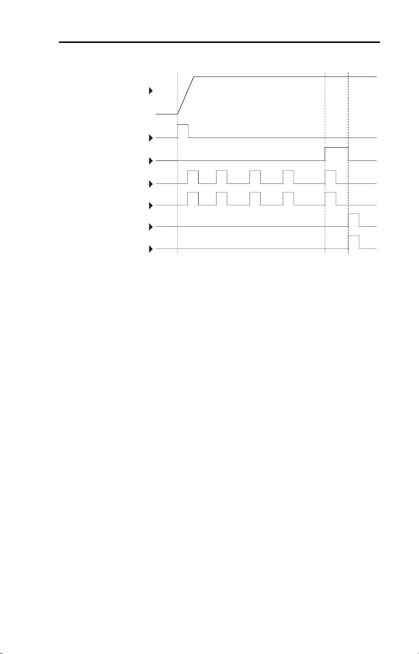
Rockwell Automation Publication 22D-UM001F-EN-E - September 2024 165
Appendix E Velocity StepLogic, Basic Logic and Timer/Counter Functions
Note that a “Reset Timer” input is not required for this example since the
“Timer Start” input both clears and starts the timer.
Di
g
ital In
2
Reset
C
ounte
r
Limit
S
witc
h
Di
g
ital In
1
C
ounter I
n
Photo E
ye
S
tar
t
Out
p
u
t
Frequenc
y
Rela
y
Ou
t

166 Rockwell Automation Publication 22D-UM001F-EN-E - September 2024
Appendix E Velocity StepLogic, Basic Logic and Timer/Counter Functions
Counter Function
Digital inputs and outputs control the counter function and are
configured with parameters A051
…A054 [Digital Inx Sel] set to 19
“Counter In” and 21 “Reset Countr”.
Digital outputs (relay and opto type) define a preset level and indicate
when the level is reached. Level parameters A056
[Relay Out Level],
A059 [Opto Out1 Level] and A062 [Opto Out2 Level] are used to set the
desired count value.
Parameters A055
[Relay Out Sel], A058 [Opto Out1 Sel] and A061
[Opto Out2 Sel] are set to 17 “Counter Out” which causes the output to
change state when the level is reached.
Example
• A photo eye is used to count packages on a conveyor line.
• An accumulator holds the packages until 5 are collected.
• A diverter arm redirects the group of 5 packages to a bundling area.
• The diverter arm returns to its original position and triggers a limit
switch that resets the counter.
• Parameters are set to the following options:
– A051
[Digital In1 Sel] set to 19 to select “Counter In”
– A052
[Digital In2 Sel] set to 21 to select “Reset Countr”
– A055
[Relay Out Sel] set to 17 to select “Counter Out”
– A056
[Relay Out Level] set to 5.0 (Counts)

Rockwell Automation Publication 22D-UM001F-EN-E - September 2024 167
Appendix E Velocity StepLogic, Basic Logic and Timer/Counter Functions
Velocity StepLogic Parameters
Table 31 – Code Descriptions for Parameters A140…A147
Table 32 – Digit 3 – Defines the action during the step currently executing.
Table 33 – Digit 2 – Defines what step to jump to or how to end program when the
logic conditions specified in Digit 1 are met.
Digit 3 Digit 2 Digit 1 Digit 0
00F1
Setting
Accel/Decel
Parameters Used
StepLogic Output
State Commanded Direction
01OffFWD
11OffREV
21OffNo Output
31OnFWD
41OnREV
5 1 On No Output
62OffFWD
72OffREV
82OffNo Output
92OnFWD
A 2 On REV
b 2 On No Output
Setting Logic
0 Jump to Step 0
1 Jump to Step 1
2 Jump to Step 2
3 Jump to Step 3
4 Jump to Step 4
5 Jump to Step 5
6 Jump to Step 6
7 Jump to Step 7
8 End Program (Normal Stop)
9 End Program (Coast-to-Stop)
A End Program and Fault (F2)

168 Rockwell Automation Publication 22D-UM001F-EN-E - September 2024
Appendix E Velocity StepLogic, Basic Logic and Timer/Counter Functions
Table 34 – Digit 1 – Defines what logic must be met to jump to a step other than the
very next step.
Table 35 – Digit 0 – Defines what logic must be met to jump to the very next step.
Setting Description Logic
0 Skip Step (jump immediately) SKIP
1 Step based on the time programmed in the respective [Stp Logic Time x]
parameter.
TIMED
2 Step if “Logic In1” is active (logically true) TRUE
3 Step if “Logic In2” is active (logically true) TRUE
4 Step if “Logic In1” is not active (logically false) FALSE
5 Step if “Logic In2” is not active (logically false) FALSE
6 Step if either “Logic In1” or “Logic In2” is active (logically true) OR
7 Step if both “Logic In1” and “Logic In2” is active (logically true) AND
8 Step if neither “Logic In1” or “Logic In2” is active (logically true) NOR
9 Step if “Logic In1” is active (logically true) and “Logic In2” is not active
(logically false)
XOR
A Step if “Logic In2” is active (logically true) and “Logic In1” is not active
(logically false)
XOR
b Step after [Stp Logic Time x] and “Logic In1” is active (logically true) TIMED AND
C Step after [Stp Logic Time x] and “Logic In2” is active (logically true) TIMED AND
d Step after [Stp Logic Time x] and “Logic In1” is not active (logically false) TIMED OR
E Step after [Stp Logic Time x] and “Logic In2” is not active (logically false) TIMED OR
F Do not step OR no “jump to”, so use Digit 0 logic IGNORE
Setting Description Logic
0 Skip Step (jump immediately) SKIP
1 Step based on the time programmed in the respective [Stp Logic Time x]
parameter.
TIMED
2 Step if “Logic In1” is active (logically true) TRUE
3 Step if “Logic In2” is active (logically true) TRUE
4 Step if “Logic In1” is not active (logically false) FALSE
5 Step if “Logic In2” is not active (logically false) FALSE
6 Step if either “Logic In1” or “Logic In2” is active (logically true) OR
7 Step if both “Logic In1” and “Logic In2” is active (logically true) AND
8 Step if neither “Logic In1” or “Logic In2” is active (logically true) NOR
9 Step if “Logic In1” is active (logically true) and “Logic In2” is not active
(logically false)
XOR
A Step if “Logic In2” is active (logically true) and “Logic In1” is not active
(logically false)
XOR
b Step after [Stp Logic Time x] and “Logic In1” is active (logically true) TIMED AND
C Step after [Stp Logic Time x] and “Logic In2” is active (logically true) TIMED AND
d Step after [Stp Logic Time x] and “Logic In1” is not active (logically false) TIMED OR
E Step after [Stp Logic Time x] and “Logic In2” is not active (logically false) TIMED OR
F Use logic programmed in Digit 1 IGNORE

Rockwell Automation Publication 22D-UM001F-EN-E - September 2024 169
Appendix F
Encoder Usage and Position
StepLogic Application
Encoder Usage
The PowerFlex 40P drive includes a pulse-train/encoder input. When
E216 [Motor Fdbk Type] is set to a value other than zero, the drive is set
to use an encoder. The drive will use the encoder in several ways
depending on the settings of other parameters. The drive will use the
encoder as shown below (listed in order of priority):
1. If enabled by P038
[Speed Reference], the encoder will be used
directly as a commanded speed (normally used with a pulse train) or
as a position reference (normally used with a quadrature encoder).
2. If not enabled by P038
[Speed Reference], when the PID Feedback
or PID Reference are set to use an encoder than the PID function will
use the encoder or pulse train input.
3. If not enabled by P038
[Speed Reference] or the PID parameters,
then if E216
[Motor Fdbk Type] is set the encoder is used for direct
feedback and trim of the speed command. The normal slip
compensation is not used in this case. Instead the drive will use the
encoder to determine actual output frequency and adjust the output
frequency to match the command. Parameters E220
[Ki Speed Loop]
and E221 [Kp Speed Loop] are used in this control loop. The
primary benefit of this mode is increased speed accuracy when
compared to open-loop slip compensation. It does not provide speed
bandwidth improvement.

170 Rockwell Automation Publication 22D-UM001F-EN-E - September 2024
Appendix F Encoder Usage and Position StepLogic Application
Wiring Notes
The encoder can supply 5V or 12V power (250 mA maximum) for an
encoder. Be sure the DIP switch is set properly for the encoder. In
general, 12V will provide higher noise immunity.
The pulse-train/encoder inputs can handle 5V, 12V, or 24V inputs. The
inputs will automatically adjust to the voltage applied and no additional
drive adjustment is necessary. If a pulse-train or single-channel input is
used, it must be wired between the A (signal) and A- (signal common)
channels.
Important: A quadrature encoder provides rotor speed and direction.
Therefore, the encoder must be wired such that the forward
direction matches the motor forward direction. If the drive
is reading encoder speed but the position regulator or other
encoder function is not working properly, remove power to
the drive and swap the A and A (NOT) encoder channels or
swap any two motor leads.Drives using FRN 2.xx and
greater will fault when an encoder is incorrectly wired and
E216 [Motor Fdbk Type] is set to option 5 “Quad Check”.
Positioning Overview
The PowerFlex 40P drive includes a simple position regulator which can
be used in a variety of position applications without the need for multiple
limit switches or photo-eyes. This can be used as a stand-alone controller
for simple applications (up to 8 positions) or in conjunction with a
controller for more flexibility.
Please note that this is not intended to replace high end servo controllers
or any application that needs high bandwidth or very high torque at low
speeds.

Rockwell Automation Publication 22D-UM001F-EN-E - September 2024 171
Appendix F Encoder Usage and Position StepLogic Application
Common Guidelines for All Applications
The position regulator can be configured for operation appropriate for a
variety of applications. Certain parameters will need to be adjusted in all
cases.
P038
[Speed Reference] must be set to option 9 “Positioning”.
E216
[Motor Fdbk Type] must be set to the match the feedback device.
Positioning mode must use E216 [Motor Fdbk Type] option 4.
E216 [Motor Fdbk Type] Options
0 “None” indicates no encoder is used. This can not be used for
positioning.
1 “Pulse Train” is a single channel input, no direction, speed feedback
only. This should not be used for positioning. The Single Channel
selection is similar to a Pulse Train, but uses the standard encoder
scaling parameters.
2 “Single Chan” is a single channel input, no direction, speed feedback
only. This should not be used for positioning. Single channel uses the
standard encoder scaling parameters.
3 “Single Check” is a single channel input with encoder signal loss
detection. The drive will fault if it detects that the input pulses do not
match the expected motor speed. This should not be used for positioning.
4 “Quadrature” is a dual channel encoder input with direction and
speed from the encoder. This may be used for positioning control.
5 “Quad Check” is a dual channel encoder with encoder signal loss
detection. The drive will fault if it detects that the encoder speed does not
match the expected motor speed. FRN 2.xx or greater supports Option 5
“Quad Check” in Positioning mode.
Important: Drives using FRN 1.xx must use option 4 “Quadrature” for
Positioning mode. FRN 1.xx does not support option 5
“Quad Check”.
A095
[Reverse Disable] should be set to option 0 “Rev Enabled” to
allow bidirectional movement necessary for position control.
A125 [Torque Perf Mode] default setting of 1 “Sensrls Vect” is
recommended for most applications to improve the low speed torque for
positioning applications. The autotune routine can be completed to
further improve the drive-motor performance.

172 Rockwell Automation Publication 22D-UM001F-EN-E - September 2024
Appendix F Encoder Usage and Position StepLogic Application
A117 [Bus Reg Mode] default setting is option 1 “Enabled”. If the
deceleration time is too short, the drive may overshoot the desired
position. For best results, a longer deceleration time may be necessary.
A117
[Bus Reg Mode] can be disabled to provide precise stopping
movements, but the deceleration time will need to be manually tuned so
that it is long enough to avoid F5 OverVoltage faults.
A082
[DB Resistor Sel] default setting is 0 “Disabled”. If improved
deceleration performance is required a Dynamic Brake resistor can be
used. If used, this parameter should be set to the appropriate setting for
the resistor selected.
E217
[Motor NP Poles] must be set to match the number of motor poles
on the motor driven by the PowerFlex 40P drive.
E218
[Encoder PPR] must be set to match the number of pulses per
revolution of the encoder used (for example, 1024 PPR Encoder).
E226
[Counts Per Unit] sets the number of encoder counts that will be
used to define one position unit. This allows the encoder positions to be
defined in terms of units important to the application. For example, if
1 cm of travel on a conveyor belt requires 0.75 turns of the motor, the
motor encoder is 1024 PPR, and the Motor Feedback type is set to
Quadrature, then this parameter would need to be set to (4 x 1024 x 0.75)
= 3072 counts for 1 cm of travel. Then all other positions could be setup
in units of “cm”.
E225
[Encoder Pos Tol] indicates the desired position tolerance for the
system. This will determine how close the drive must be to the
commanded position before the drive will indicate “At Home” or “At
Position” in units of raw encoder pulses. This has no effect on the actual
positioning control of the motor.

Rockwell Automation Publication 22D-UM001F-EN-E - September 2024 173
Appendix F Encoder Usage and Position StepLogic Application
Positioning Operation
Parameter E222 [Positioning Mode] must be set to properly match the
desired operation of the positioning function.
E222 [Positioning Mode] Options
0 “Time Steps” uses Step Logic times. This mode ignores the Step
Logic settings and moves through the steps (Step 0 to Step 7 and back to
Step 0) based on the times programmed into A150
…A157 [Stp Logic
Time x]. This can be used when the desired position is based only on
time. In addition, this mode only accepts absolute positions in a positive
direction from “home”. This option provides an easy way to implement a
simple positioning program or to test the basic positioning setup. For
additional flexibility one of the other settings should be used.
1 “Preset Input” directly commands movement to any step based on the
status of the digital inputs programmed for “Preset Freq”. This setting
ignores the Step Logic Commands settings and instead the drive will
move directly to whatever step is currently commanded by A070
…A077
[Preset Freq x] and E230…E244 [Step Units x]. This is useful when an
application needs direct access to any position step based on discrete
inputs. This mode moves in the forward direction from Home and is an
absolute move.
Important: Advanced Step Logic options such as incremental move are
not available in this mode.
2 “Step Logic” provides a highly flexible mode of operation. This can
be used to move through the steps (Step 0 to Step 7 and back to Step 0)
or can jump to a different step at any time based on time or the status of
digital inputs or communication commands. In this mode the drive
always starts at Step 0 of the Step Logic profile.
3 “Preset-StpL” is identical to option 2 “Step Logic” except the drive
will use the current status of the Preset Inputs to determine which Step
Logic step to begin. This only affects the initial step. After start, the drive
will move through the steps in the same manner as if setting 2 was
selected.
4 “StpLogic-Lst” is identical to option 2 “Step Logic” except the drive
will use the step prior to its last stop command to determine which Step
Logic step to begin. This only affects the initial step. After start, the drive
will move through the steps in the same manner as if option 2 was
selected. This allows a process to be stopped and then restarted at the
position where it stopped.

174 Rockwell Automation Publication 22D-UM001F-EN-E - September 2024
Appendix F Encoder Usage and Position StepLogic Application
In all position modes, the following parameters will control the
characteristics at each step:
E230…E244 [Step Units x]
These are the number value to the left of the decimal (whole number) of
the 8 positions desired for an application, beginning with Step 0 (E230
)
and continuing with each step until Step 7 (E244
). For example, enter 2
into this parameter if you would like a commanded position of 2.77.
E231…E245 [Step Units F x]
These are the number value to the right of the decimal (the portion less
than 1) of the 8 positions desired for an application, beginning with Step
0 (E231
) and continuing with each step until Step 7 (E245). For
example, enter 0.77 into this parameter if you would like a commanded
position of 2.77.
A070…A077 [Preset Freq x]
In Positioning mode, each preset frequency parameter defines the
maximum frequency the drive will run at during the corresponding step.
For example, if [Preset Freq 2] is set to 40 Hz, the drive will accelerate to
40 Hz maximum when moving to Position 2.
Important: The default value for A070
[Preset Freq 0] is 0.00 Hz. This
value needs to be changed or the drive will not be able to
move during Step 0.
A150…A157 [Stp Logic Time x]
In Positioning mode, each Step Logic Time parameter defines the time
the drive will remain in each corresponding step if that step is
time-based. For example, if A152
[Stp Logic Time 2] is set to 5.0
seconds and that step is time-based, the drive will remain in Step 2 for
5.0 seconds. Note that this is the total time in that step, not the time at
that position. Therefore, it will include the time needed to accelerate,
run, and decelerate to that position.
Frequency Source Step Source Position Source
A070 [Preset Freq 0] A140 [Step Logic 0] E230 [Step Units 0]
A071 [Preset Freq 1] A141 [Step Logic 1] E232 [Step Units 1]
A072 [Preset Freq 2] A142 [Step Logic 2] E234 [Step Units 2]
A073 [Preset Freq 3] A143 [Step Logic 3] E236 [Step Units 3]
A074 [Preset Freq 4] A144 [Step Logic 4] E238 [Step Units 4]
A075 [Preset Freq 5] A145 [Step Logic 5] E240 [Step Units 5]
A076 [Preset Freq 6] A146 [Step Logic 6] E242 [Step Units 6]
A077 [Preset Freq 7] A147 [Step Logic 7] E244 [Step Units 7]

Rockwell Automation Publication 22D-UM001F-EN-E - September 2024 175
Appendix F Encoder Usage and Position StepLogic Application
A140…A147 [Stp Logic x] – When a positioning mode is selected that
utilizes the Step Logic functions these parameters allow additional
flexibility and control various aspects of each step. Note that in
Positioning mode these parameters have a different function than when
used for normal velocity Step Logic. Each of the 4 digits controls one
aspect of the each position step. The following is a listing of the
available settings for each digit:
Note: Incremental move commands will cause the drive to move the
amount specified based on the current position. Absolute commands are
always with reference to “Home”.
E246
[Pos Reg Filter] provides a low pass filter at the input of the
position regulator.
Logic For Next Step Digit 0
Logic to Jump to a Different Step Digit 1
Different Step to Jump Digit 2
Step Settings Digit 3
Settings For Positioning (Digit 3)
Required
Setting
Accel/Decel
Param. Used
StepLogic
Output State
Direction
From Home
Type Of
Command
0
1
2
3
4
5
6
7
8
9
A
b
C
d
E
F
Accel/Decel 1
Accel/Decel 1
Accel/Decel 1
Accel/Decel 1
Accel/Decel 1
Accel/Decel 1
Accel/Decel 1
Accel/Decel 1
Accel/Decel 2
Accel/Decel 2
Accel/Decel 2
Accel/Decel 2
Accel/Decel 2
Accel/Decel 2
Accel/Decel 2
Accel/Decel 2
Off
Off
Off
Off
On
On
On
On
Off
Off
Off
Off
On
On
On
On
FWD
FWD
REV
REV
FWD
FWD
REV
REV
FWD
FWD
REV
REV
FWD
FWD
REV
REV
Absolute
Incremental
Absolute
Incremental
Absolute
Incremental
Absolute
Incremental
Absolute
Incremental
Absolute
Incremental
Absolute
Incremental
Absolute
Incremental
Settings (Digit 2) Settings (Digit 1 and Digit 0)
0 = Jump to Step 0
1 = Jump to Step 1
2 = Jump to Step 2
3 = Jump to Step 3
4 = Jump to Step 4
5 = Jump to Step 5
6 = Jump to Step 6
7 = Jump to Step 7
8 = End Program (Normal Stop)
9 = End Program (Coast-to-Stop)
A = End Program and Fault (F2)
0 = Skip Step (Jump Immediately)
1 = Step Based on [Stp Logic Time x]
2 = Step if “Logic In1” is Active
3 = Step if “Logic In2” is Active
4 = Step if “Logic In1” is Not Active
5 = Step if “Logic In2” is Not Active
6 = Step if either “Logic In1” or “Logic In2” is Active
7 = Step if both “Logic In1” and “Logic In2” is Active
8 = Step if neither “Logic In1” or “Logic In2” is Active
9 = Step if “Logic In1” is Active and “Logic In2” is Not Active
A = Step if “Logic In2” is Active and “Logic In1” is Not Active
b = Step after [Stp Logic Time x] and “Logic In1” is Active
C = Step after [Stp Logic Time x] and “Logic In2” is Active
d = Step after [Stp Logic Time x] and “Logic In1” is Not Active
E = Step after [Stp Logic Time x] and “Logic In2” is Not Active
F = Do Not Step/Ignore Digit 2 Settings

176 Rockwell Automation Publication 22D-UM001F-EN-E - September 2024
Appendix F Encoder Usage and Position StepLogic Application
E247 [Pos Reg Gain] is a single adjustment for increasing or decreasing
the responsiveness of the position regulator. For faster response, the filter
should be reduced and/or the gain should be increased. For smoother
response with less overshoot, the filter should be increased and/or the
gain should be reduced. In general, the gain will have a larger effect on
most systems than the filter.
Homing Routine
This drive supports incremental encoders only. Therefore, when the drive
powers up it will reset the current position to zero. If this is known to be
correct the position routine can be started without further adjustment.
However, in most applications the drive will need to be “homed” after
each power-up and prior to starting the position routine.
This can be accomplished in one of the following two ways:
1. Manual Homing - Program the following drive parameters:
A051…A054 [Digital Inx Sel] = 36 “Pos Redefine”
Program one of the digital inputs to option 36 “Pos Redefine”. Then,
move the system into the home position via a run command, a jog
command, or by manually moving the system into the home position.
Then, toggle the “Pos Redefine” input. This will set the drive to
“Home” at its current position and d308
[Units Traveled H] and d309
[Units Traveled L] are set to zero. Alternately, the “Pos Redefine” bit
in E248
[Enh Control Word] can be toggled instead of utilizing a
digital input.
Important: The “Pos Redefine” input or bit must be returned to
inactive before starting the position routine. Otherwise
the drive will continuously read a position of “0”
(home) and the position routine will not function
correctly.
2. Automatic Homing to Limit Switch–Program the following drive
parameters:
A051…A054 [Digital Inx Sel] = 34 “Find Home”
Program one of the digital inputs to option 34 “Find Home”
A051…A054 [Digital Inx Sel] = 33 “Home Limit”
Program one of the digital inputs to option 33 “Home Limit”.
Normally, the “Home Limit” input would be wired to a proximity
switch or photo-eye and will indicate the system is in the home
position.

Rockwell Automation Publication 22D-UM001F-EN-E - September 2024 177
Appendix F Encoder Usage and Position StepLogic Application
E223 [Find Home Freq]
This parameter sets the frequency the drive will use while it is
moving to the home position during the automatic homing routine.
E224 [Find Home Dir]
This parameter sets the direction the drive will use while it is moving
to the home position during the automatic homing routine.
To begin the automatic homing routine, activate the “Find Home” input
and then initiate a valid start command. The drive will then ramp to the
speed set in E223
[Find Home Freq] and in the direction set in E224
[Find Home Dir] until the digital input defined as “Home Limit” is
activated. If the drive passes this point too quickly it will then reverse
direction at 1/10th E223
[Find Home Freq] to the point where the Home
Limit switch reactivates. Approximately one second after the routine
finds home the drive will stop. Alternately, the “Find Home Freq” and/or
“Home Limit” bits in E248
[Enh Control Word] can be activated instead
of utilizing a digital input. The inputs or bits should be returned to
inactive after the routine is complete.
Important: After the position is reached the drive will stop. If the Find
Home is removed before the homing is complete, the drive
will begin running the position routine without the proper
home. In this case Home will not be reset and the position
will be in relation to the power up position.
Encoder and Position Feedback
Parameter d304 [Speed Feedback] and d305 [Speed Feedback F]
indicate the measured speed feedback or the calculated speed feedback
when no feedback device is selected. Parameter d304 [Speed Feedback]
is the number value to the left of the decimal (whole number) and d305
[Speed Feedback F] is the value to the right of the decimal (the portion
less than 1).
d306 [Encoder Speed]
Parameter d306
[Encoder Speed] and d307 [Encoder Speed F] indicate
the measured speed of the feedback device. This is useful if the encoder
is not used for motor speed control. However, the encoder must be used
for some purpose in order for [Encoder Speed] to indicate a value.
Parameter d306 is the number value to the left of the decimal (whole
number) and d307 is the number to the right of the decimal (the portion
less than 1).

178 Rockwell Automation Publication 22D-UM001F-EN-E - September 2024
Appendix F Encoder Usage and Position StepLogic Application
d308 [Units Traveled]
Parameter d308 [Units Traveled H] and d309 [Units Traveled L] indicate
the current position of the system in terms of units away from Home.
Parameter d308 is the number value to the left of the decimal (whole
number) and d309 is the number to the right of the decimal (the portion
less than 1).
d301 [Drive Status 2]
Parameter d301
[Drive Status 2] indicates the status of the positioning
functions. The indication bits are:
Bit 0 “Dir Positive” indicates the current direction the drive has moved
from Home.
Bit 1 “At Position” indicates whether the drive is at its commanded
position. If the drive is within E225
[Encoder Pos Tol] of the
commanded position, this bit will be active.
Bit 2 “At Home” indicates whether the drive is at Home. If the drive is
within E225
[Encoder Pos Tol] of “Home”, this bit will be active.
Bit 3 “Drive Homed” indicates whether the drive has been homed since
power-up. This bit will be active once the drive has been homed either
manually or automatically. It will remain active until the next power
down.
Use Over Communications
If 8 steps are not adequate for the application or if dynamic program
changes are required, many of the positioning functions can be
controlled via an active communication network. The following
parameters will allow this control.
E207 [Comm Write Mode]
Repeated writes to parameters over a communication network can cause
damage to the drive EEPROM. This parameter allows the drive to accept
parameter changes without writing to the EEPROM.
Important: Parameter values set prior to setting option 1 “RAM only”
will be saved in drive non-volatile memory (EEPROM).
E249 [Cmd Stat Select]
Selects velocity-specific or position/fibers-specific Command and Status
Word bit definitions for use over a communication network.

Rockwell Automation Publication 22D-UM001F-EN-E - September 2024 179
Appendix F Encoder Usage and Position StepLogic Application
E248 [Enh Control Word]
This parameter allows many of the positioning functions to be completed
via parameter control using an explicit message. This allows the
operation over communications instead of with hardware inputs. The bits
have the same functions as the digital input options of the same name.
Options relating to positioning are:
Bit 0 “Home Limit”
Bit 1 “Find Home”
Bit 2 “Hold Step”
Bit 3 “Pos Redefine”
E230…E244 [Step Units x]
All of the position steps can be written to while the drive is running. The
changes will take place at the next move. For example, if step 0 is
over-written while the drive is moving to step 0, the drive will move to
the previous commanded position at step 0. The next time the drive is
commanded to return to step 0 it will proceed to the new position. One
possible use of this capability is when an application requires full control
of the movement by a controller external to the drive. The Step Logic
program might be written to jump from step 0 back to step 0 when Input
1 is active. The controller could write any desired position to step 0 and
then toggle the input 1 bit of E248 [Enh Control Word] to cause the drive
to move to the new position. This allows almost unlimited flexibility and
can be used with absolute or incremental moves.
Setup Notes
The programming tools (Connected Components Workbench and
DriveTools SP software) can make setup of the positioning functions
much easier. See the latest versions for additional tools or wizards which
can aid in the setup.

180 Rockwell Automation Publication 22D-UM001F-EN-E - September 2024
Appendix F Encoder Usage and Position StepLogic Application
Notes:

Rockwell Automation Publication 22D-UM001F-EN-E - September 2024 181
Appendix G
PID Set Up
PID Loop
The PowerFlex 40P drive has a built-in PID (proportional, integral,
differential) control loop. The PID loop is used to maintain a process
feedback (such as pressure, flow or tension) at a desired set point. The
PID loop works by subtracting the PID feedback from a reference and
generating an error value. The PID loop reacts to the error, based on the
PID Gains, and outputs a frequency to try to reduce the error value to 0.
To enable the PID loop, parameter A132
[PID Ref Sel] must be set to an
option other than 0 “PID Disabled”.
Exclusive Control and Trim Control are two basic configurations where
the PID loop may be used.
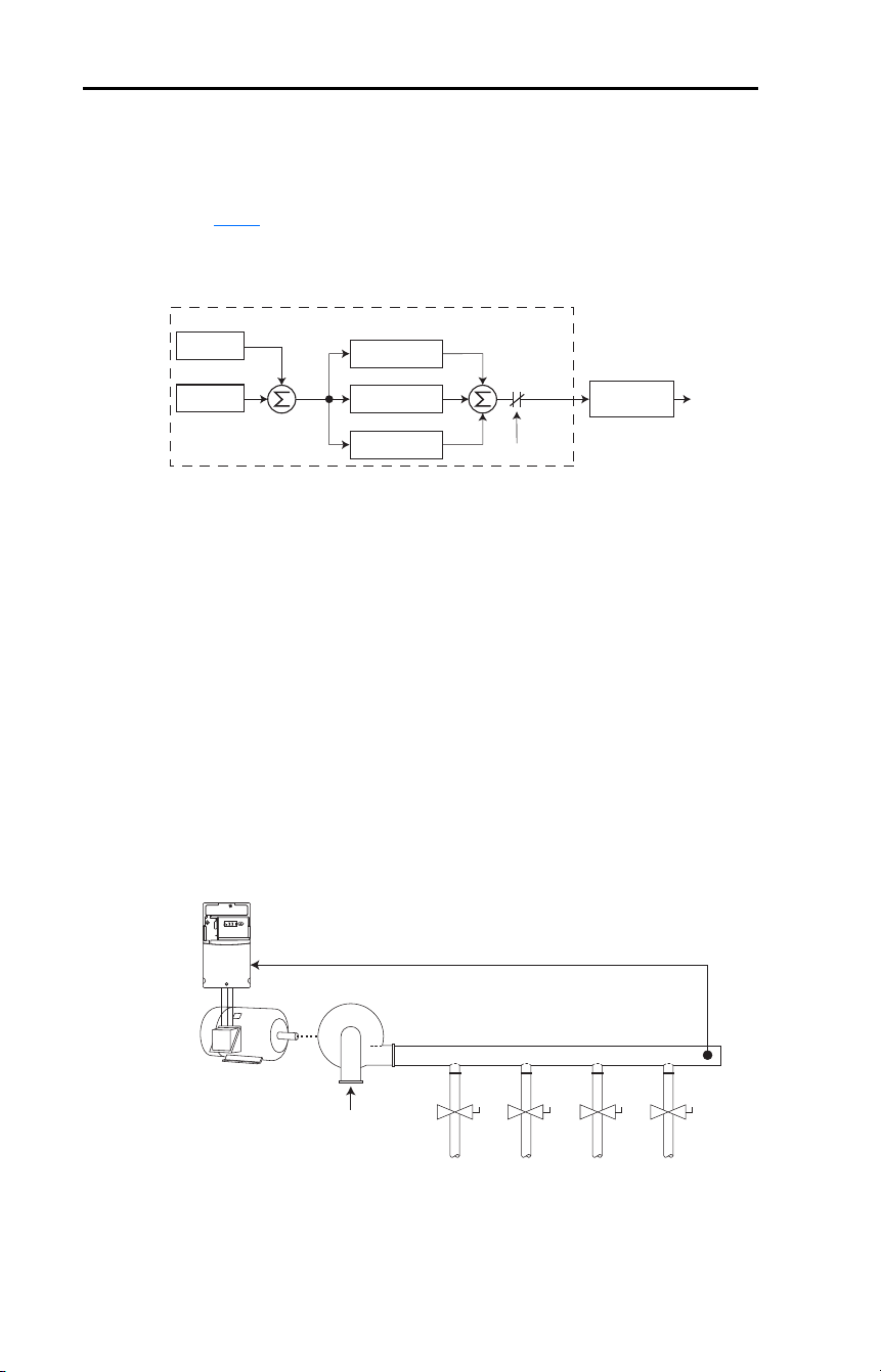
182 Rockwell Automation Publication 22D-UM001F-EN-E - September 2024
Appendix G PID Set Up
Exclusive Control
In Exclusive Control, the Speed Reference becomes 0, and the PID
Output becomes the entire Freq Command. Exclusive Control is used
when A132 [PID Ref Sel] is set to option 1, 2, 3, 4, or 5. This
configuration does not require a master reference, only a desired set
point, such as a flow rate for a pump.
Example
• In a pumping application, the PID Reference equals the Desired
System Pressure set point.
• The Pressure Transducer signal provides PID Feedback to the drive.
Fluctuations in actual system pressure, due to changes in flow, result
in a PID Error value.
• The drive output frequency increases or decreases to vary motor
shaft speed to correct for the PID Error value.
• The Desired System Pressure set point is maintained as valves in the
system are opened and closed causing changes in flow.
• When the PID Control Loop is disabled, the Commanded Speed is
the Ramped Speed Reference.
–
+
PID Prop Gain
PID Loop
PID Integ Time
PID Diff Rate
PID Enabled
PID Fdbk
PID Ref
PID
Error
+
+
+
PID
Output
Accel/Decel
Ramp
Freq
Command
Pump
PID Feedback =
Pressure transducer signal
PID Reference =
Desired system pressure
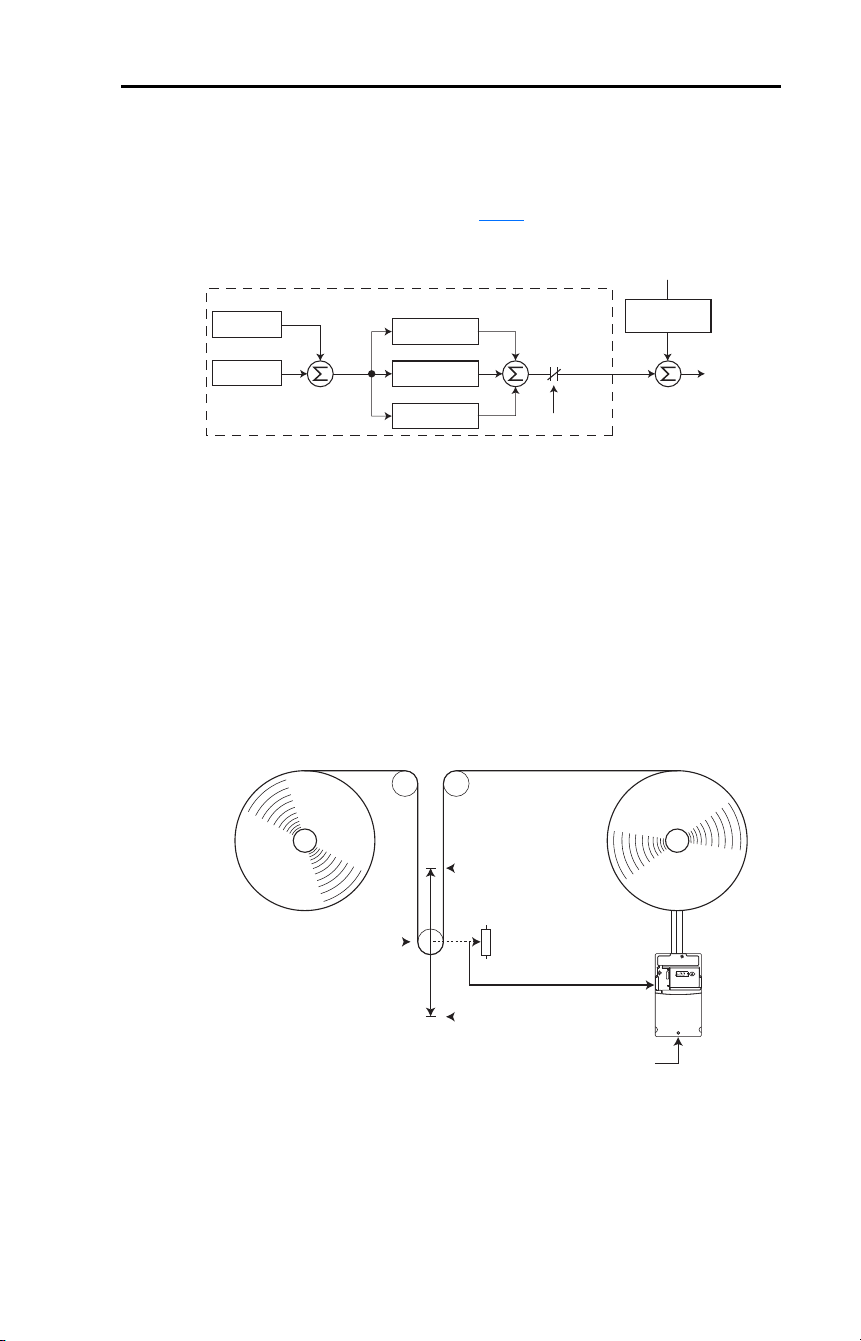
Rockwell Automation Publication 22D-UM001F-EN-E - September 2024 183
Appendix G PID Set Up
Trim Control
In Trim Control, the PID Output is added to the Speed Reference. In
Trim mode, the output of the PID loop bypasses the accel/decel ramp as
shown. Trim Control is used when A132 [PID Ref Sel] is set to option 6,
7, 8, 9, or 10.
Example
• In a winder application, the PID Reference equals the Equilibrium
set point.
• The Dancer Pot signal provides PID Feedback to the drive.
Fluctuations in tension result in a PID Error value.
• The Master Speed Reference sets the wind/unwind speed.
• As tension increases or decreases during winding, the Speed
Reference is trimmed to compensate. Tension is maintained near the
Equilibrium set point.
–
+
PID Prop Gain
PID Loop
PID Integ Time
PID Di Rate
PID Enabled
P038 [Speed Reference]
PID Fdbk
PID Ref
PID
Error
+
+
+
+
PID
Output
Output
frequency
+
Accel/Decel
Ramp
P038 [Speed Reference]
0V
PID Feedback =
Dancer pot signal
10V
PID Reference =
Equilibrium set point

184 Rockwell Automation Publication 22D-UM001F-EN-E - September 2024
Appendix G PID Set Up
PID Reference and Feedback
Parameter A132 [PID Ref Sel] is used to enable the PID mode (A132 = 0
“PID Disabled”) and to select the source of the PID Reference. If A132
[PID Ref Sel] is not set to 0 “PID Disabled”, PID can still be disabled by
select programmable digital input options (parameters A051
…A054)
such as “Jog”, “Local” or “PID Disable”.
Table 36 – A132 [PID Ref Sel] Options
A133 [PID Feedback Sel] is used to select the source of the PID
feedback.
Table 37 – A133 [PID Feedback Sel] Options
Option Description
0 “PID Disabled” Disables the PID loop (default setting)
1 “PID Setpoint“ Selects Exclusive Control. A137 [PID Setpoint] is used to set the value of
the PID Reference
2 “0…10V Input” Selects Exclusive Control. Selects the 0…10V Input. The PID does not
function with a bipolar analog input. It ignores any negative voltages and
treat them like a zero.
3 “4…20 mA Input” Selects Exclusive Control. Selects the 4…20 mA Input.
4 “Comm Port” Selects Exclusive Control. The reference word from a communication
network (see Appendix
C for details on the reference word) such as
Modbus RTU or DeviceNet becomes the PID Reference. The value sent
over the network is scaled so that P035 [Maximum Freq] x 10 = 100%
reference. For example, with [Maximum Freq] = 60 Hz, a value of 600
sent over the network would represent 100% reference.
5 “Encoder” Selects Exclusive Control. Encoder or Pulse train is used as an input for
the PID Reference.
6 “Setpnt, Trim” Selects Trim Control. A137 [PID Setpoint] is used to set the value of the
PID Reference.
7 “0…10V, Trim” Selects Trim Control. Selects the 0…10V Input. The PID does not
function with a bipolar analog input. It ignores any negative voltages and
treat them like a zero.
8 “4…20 mA, Trim” Selects Trim Control. Selects the 4…20 mA Input.
9 “Comm, Trim” Selects Trim Control. The reference word from a communication network
(see Appendix
C for details on the reference word) such as Modbus RTU
or DeviceNet becomes the PID Reference. The value sent over the
network is scaled so that P035 [Maximum Freq] x 10 = 100% reference.
For example, with [Maximum Freq] = 60 Hz, a value of 600 sent over the
network would represent 100% reference.
10 “Encoder,Trim” Selects Trim Control. Encoder or Pulse train is used as a trim input for the
PID Feedback.
Option Description
0 “0…10V Input” Selects the 0…10V Input (default setting). The PID does not function with
a bipolar analog input. It ignores any negative voltages and treat them
like a zero.
1 “4…20 mA Input“ Selects the 4…20 mA Input.
2 “Comm Port” The reference word from a communication network (see Appendix
C for
details on the reference word) such as Modbus RTU or DeviceNet
becomes the PID Feedback. The value sent over the network is scaled so
that P035 [Maximum Freq] x 10 = 100% Feedback. For example, with
[Maximum Freq] = 60 Hz, a value of 600 sent over the network would
represent 100% Feedback.
3 “Encoder” Encoder or Pulse train is used as an input for the PID Feedback.
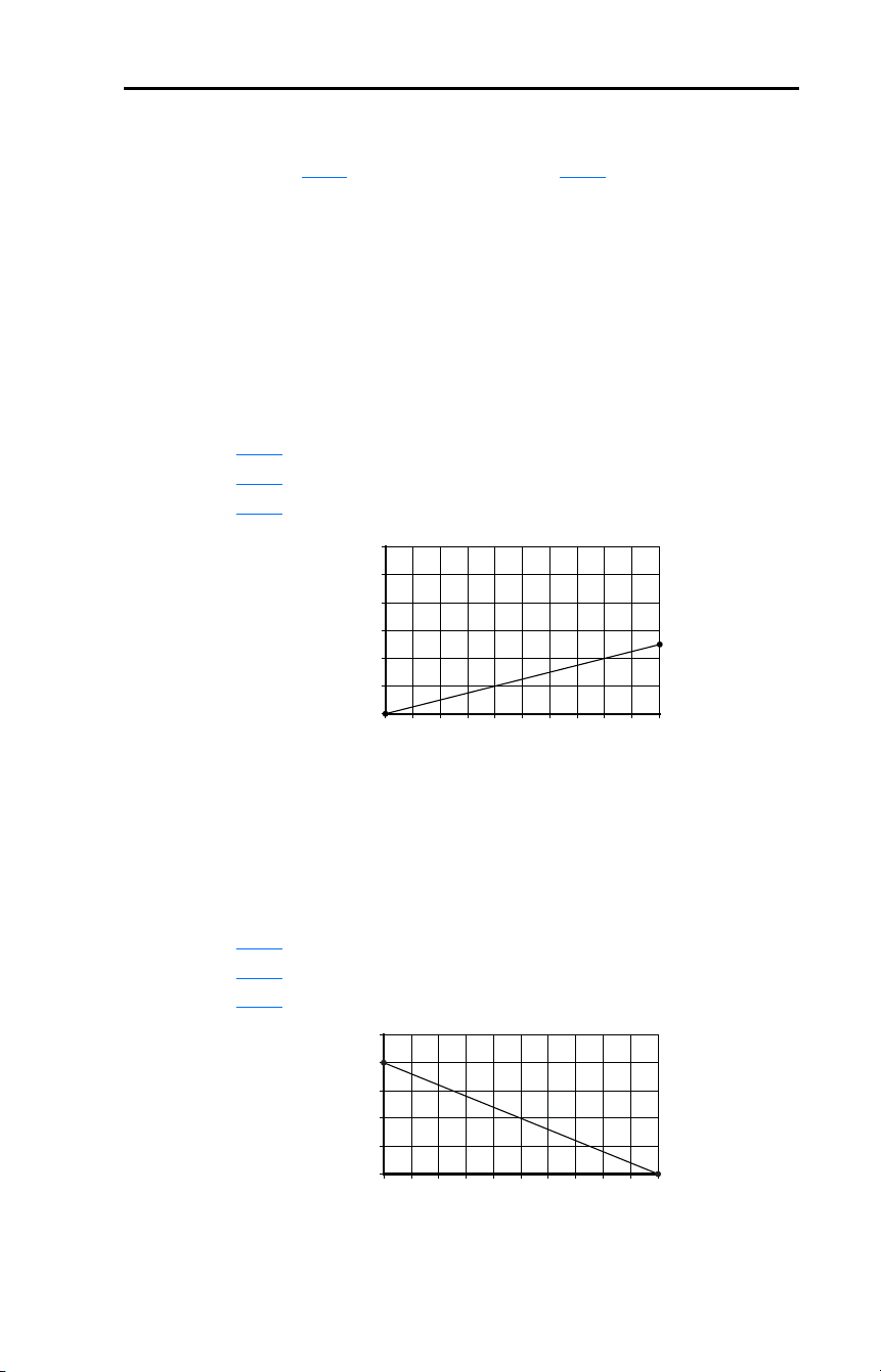
Rockwell Automation Publication 22D-UM001F-EN-E - September 2024 185
Appendix G PID Set Up
Analog PID Reference Signals
Parameters A110 [Anlg In 0…10V Lo] and A111 [Anlg In 0…10V Hi]
are used to scale or invert an analog PID Reference or PID Feedback.
Examples
Scale Function
For a 0-5 volt signal, the following parameter settings are used so that a 0
volt signal = 0% PID Reference and a 5 volt signal = 100% PID
Reference.
• A110
[Anlg In 0-10V Lo] = 0.0%
• A111 [Anlg In 0-10V Hi] = 50.0%
• A132
[PID Ref Sel] = 2 “0-10V Input”
Invert Function
For a 4…20 mA signal, the following parameter settings are used so that
a 20 mA signal = 0% PID Reference and a 4 mA signal = 100% PID
Reference.
• A112
[Anlg In4…20 mA Lo] = 100.0%
• A113
[Anlg In4…20 mA Hi] = 0.0%
• A132
[PID Ref Sel] = 3 “4…20 mA Input”
0102030405060708090100
PID Reference (%)
Input Volts
2
4
6
8
10
12
0 10 20 30 40 50 60 70 80 90 100
PID Reference (%)
4… 20 m A Input
4
8
12
16
20
24
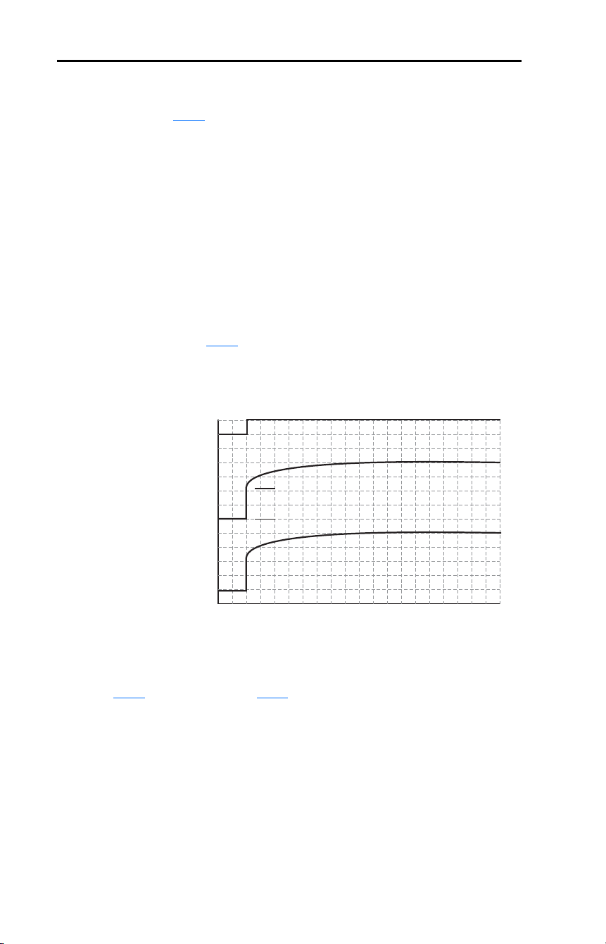
186 Rockwell Automation Publication 22D-UM001F-EN-E - September 2024
Appendix G PID Set Up
PID Deadband
Parameter A138 [PID Deadband] is used to set a range, in percent, of the
PID Reference that the drive will ignore.
Example
• [PID Deadband] is set to 5.0
• The PID Reference is 25.0%
• The PID Regulator will not act on a PID Error that falls between 20.0
and 30.0%
PID Preload
The value set in A139 [PID Preload], in Hertz is pre-loaded into the
integral component of the PID at any start or enable. This causes the
drives frequency command to initially jump to that preload frequency,
and the PID loop starts regulating from there.
PID Limits
A130 [PID Trim Hi] and A131 [PID Trim Lo] are used to limit the PID
output and are only used in trim mode. [PID Trim Hi] sets the maximum
frequency for the PID output in trim mode. [PID Trim Lo] sets the
reverse frequency limit for the PID output in trim mode. Note that when
the PID reaches the Hi or Lo limit, the PID regulator stops integrating so
that windup does not occur.
PID Enabled
Freq Cm d
PID O utput
PID Pre-load valu e
PID Pre-lo ad valu e > 0

Rockwell Automation Publication 22D-UM001F-EN-E - September 2024 187
Appendix G PID Set Up
PID Gains
The proportional, integral, and differential gains make up the PID
regulator.
• A134 [PID Prop Gain]
The proportional gain (unitless) affects how the regulator reacts to
the magnitude of the error. The proportional component of the PID
regulator outputs a speed command proportional to the PID error. For
example, a proportional gain of 1 outputs 100% of max frequency
when the PID error is 100% of the analog input range. A larger value
for [PID Prop Gain] makes the proportional component more
responsive, and a smaller value makes it less responsive. Setting
[PID Prop Gain] to 0.00 disables the proportional component of the
PID loop.
• A135
[PID Integ Time]
The integral gain (units of seconds) affects how the regulator reacts
to error over time and is used to eliminate steady state error. For
example, with an integral gain of 2 seconds, the output of the integral
gain component integrates up to 100% of max frequency when the
PID error is 100% for 2 seconds. A larger value for [PID Integ Time]
makes the integral component less responsive, and a smaller value
makes it more responsive. Setting [PID Integ Time] to 0.0 disables
the integral component of the PID loop.
• A136
[PID Diff Rate]
The Differential gain (units of 1/seconds) affects the rate of change
of the PID output. The differential gain is multiplied by the
difference between the previous error and current error. Thus, with a
large error the D has a large effect and with a small error the D has
less of an effect. This parameter is scaled so that when it is set to
1.00, the process response is 0.1% of [Maximum Freq] when the
process error is changing at 1% / second. A larger value for [PID Diff
Rate] makes the differential term have more of an effect and a small
value makes it have less of an effect. In many applications, the D
gain is not needed. Setting [PID Diff Rate] to 0.00 (factory default)
disables the differential component of the PID loop.

188 Rockwell Automation Publication 22D-UM001F-EN-E - September 2024
Appendix G PID Set Up
Guidelines for Adjusting the PID Gains
1. Adjust the proportional gain. During this step it may be desirable to
disable the integral gain and differential gain by setting them to 0.
After a step change in the PID Feedback:
– If the response is too slow increase A134
[PID Prop Gain].
– If the response is too quick and/or unstable (see Figure 23
),
decrease A134 [PID Prop Gain].
– Typically, A134 [PID Prop Gain] is set to some value below the
point where the PID begins to go unstable.
2. Adjust the integral gain (leave the proportional gain set as in Step 1).
After a step change in the PID Feedback:
– If the response is too slow (see Figure 24
), or the PID Feedback
does not become equal to the PID Reference, decrease A135
[PID Integ Time].
– If there is a lot of oscillation in the PID Feedback before settling
out (see Figure 25
), increase A135 [PID Integ Time].
3. At this point, the differential gain may not be needed. However, if
after determining the values for A134 [PID Prop Gain] and A135
[PID Integ Time]:
– Response is still slow after a step change, increase A136
[PID
Diff Rate].
– Response is still unstable, decrease A136 [PID Diff Rate].
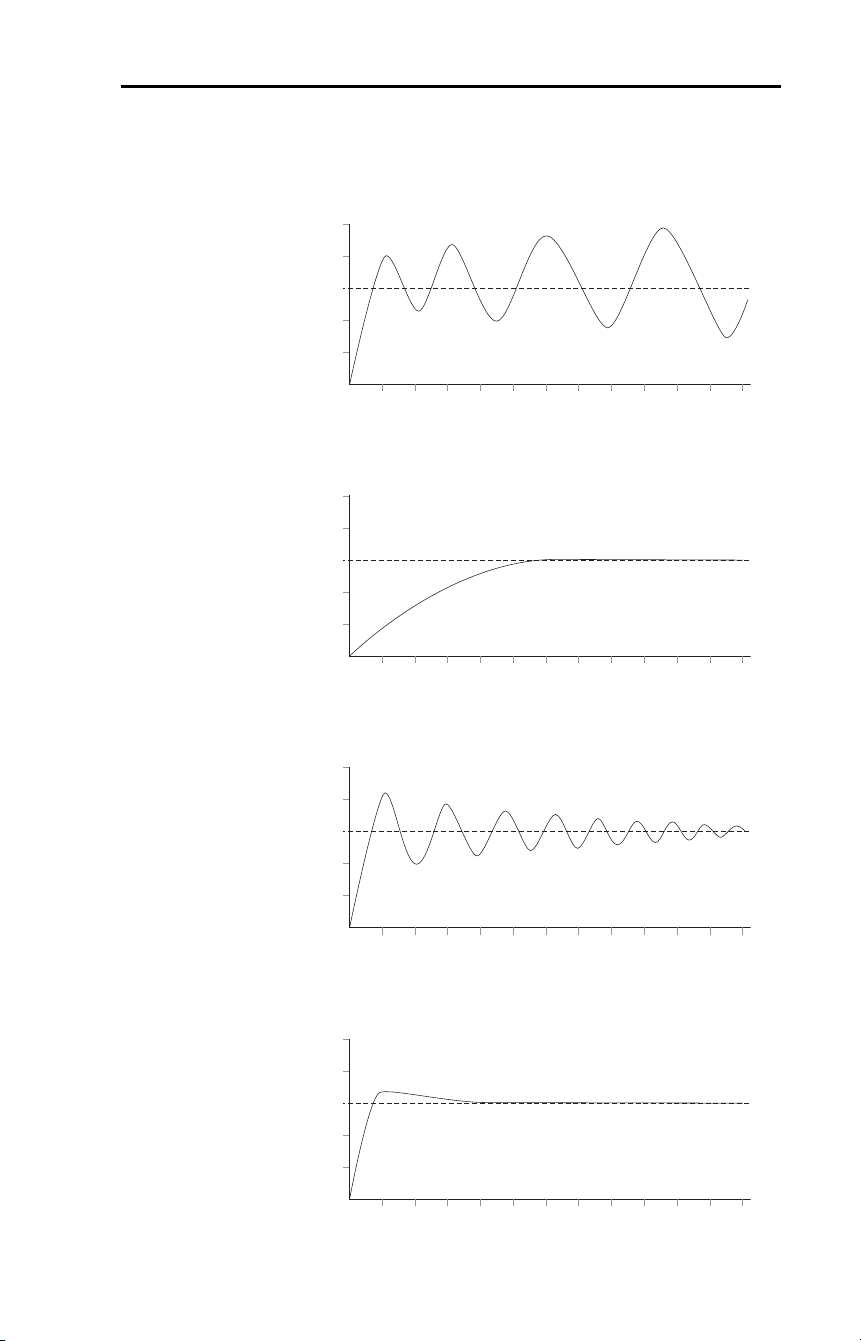
Rockwell Automation Publication 22D-UM001F-EN-E - September 2024 189
Appendix G PID Set Up
The following figures show some typical responses of the PID loop at
different points during adjustment of the PID Gains.
Figure 23 – Unstable
Figure 24 – Slow Response – Over Damped
Figure 25 – Oscillation – Under Damped
Figure 26 – Good Response – Critically Damped
PID Feedback
PID Reference
Time
PID Feedback
PID Reference
Time
PID Feedback
PID Reference
Time
PID Feedback
PID Reference
Time

190 Rockwell Automation Publication 22D-UM001F-EN-E - September 2024
Appendix G PID Set Up
Notes:

Rockwell Automation Publication 22D-UM001F-EN-E - September 2024 191
Appendix H
Plate Drive Installation Instructions
Introduction
The PowerFlex 40P drive is available in a plate drive version without
heatsink. This is designed to allow mounting to a customer supplied
heatsink. This may be a large heatsink to be shared by multiple drives, a
large thermal mass that is part of a system, or some other heat-sinking
system. Care must be taken to insure the heatsink used provides adequate
cooling for the drive power components as well as a flat and clean
surface for a proper thermal interface.
General Requirements
The drive is designed to operate with the drive enclosed and the heatsink
exposed for improved cooling. Therefore, it is expected that the drive
control section will experience a higher ambient temperature than the
heatsink.
Table 38 – Maximum Surrounding Air Temperature
Note that the standard 480V 11 kW (15 HP) drive includes an internal
inductor. This inductor cannot be included in the plate drive. Therefore,
this rating requires the use of an external DC inductor or an AC input
reactor as described in Table 23
.
Heatsink 40 °C (104 °F)
Drive 50 °C (122 °F)
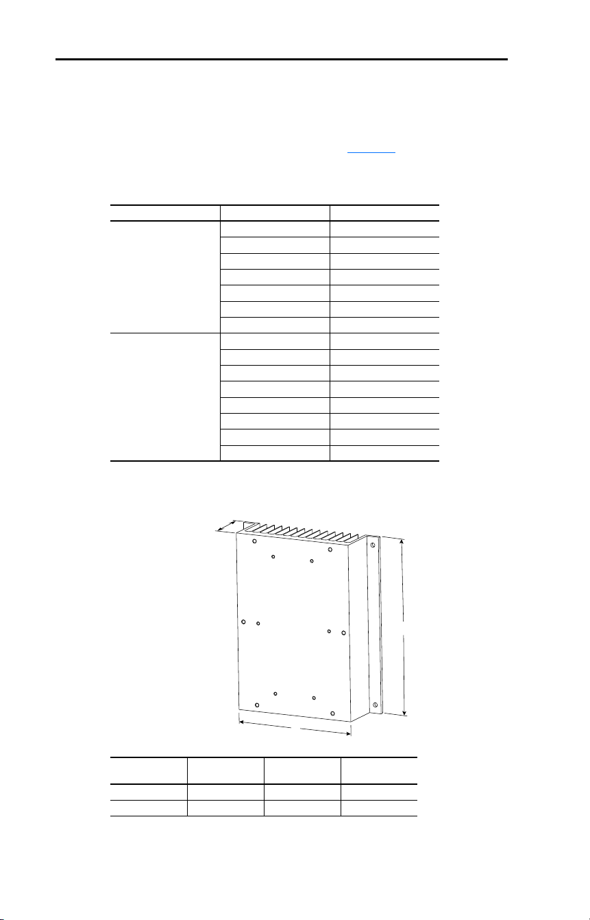
192 Rockwell Automation Publication 22D-UM001F-EN-E - September 2024
Appendix H Plate Drive Installation Instructions
Heatsink Thermal Capacity
The heatsink provided must have the thermal capacity to cool the drive
under worst-case loading conditions as well as for short duration
overload conditions in the application. See Table 18
for estimated watts
loss data.
Table 39 – Required Heatsink Degrees C/W Capabilities
Figure 27 – Approximate Heatsink Dimensions for One Drive without Heatsink Fan
Plate Drive Input Voltage kW (HP) Heatsink °C/W Needed
230V AC 0.4 (0.5) 1.59
0.75 (1.0) 0.88
1.5 (2.0) 0.56
2.2 (3.0) 0.35
3.7 (5.0) 0.23
5.5 (7.5) 0.18
7.5 (10) 0.13
460V AC 0.4 (0.5) 2.06
0.75 (1.0) 1.17
1.5 (2.0) 0.73
2.2 (3.0) 0.47
3.7 (5.0) 0.26
5.5 (7.5) 0.25
7.5 (10) 0.20
11 (15) 0.13
Drive Frame Size
A
mm (in.)
B
mm (in.)
C
mm (in.)
B 214 (8.43) 250 (9.84) 63.1 (2.48)
C 300 (11.81) 325 (12.8) 138.2 (5.44)
C
B
A
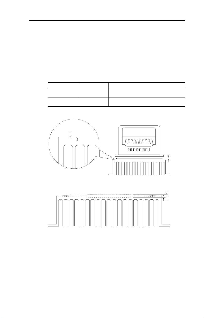
Rockwell Automation Publication 22D-UM001F-EN-E - September 2024 193
Appendix H Plate Drive Installation Instructions
Heatsink Surface and Flatness Requirements
The drive comes with a thermal pad designed to provide a good interface
between the drive and heatsink. However, in order for this to function
properly the mounting surface for the plate drive must be clean and free
of dirt, oil, and debris. It must be very flat and smooth and should have
no scratches, nicks, or gouges. All mounting holes must be clean and
deburred.
Table 40 – Surface Requirements
Figure 28 – Smoothness Tolerance and Surface Pad Thickness
Figure 29 – Trueness Tolerance
Attribute Requirement Description
Surface Finish 1.6 µM (Ra Method) Smoothness – Overall surface texture free from
imperfections (scratches, nicks, or gouges)
Surface Flatness ± 0.0381 mm
(0.0015 in.)
Trueness – Free from warps, twists, and concavity
(depressions)
+0.0127 mm
(+0.0005 in.)
0.127 mm
(0.005 in.)
–0.0127 mm
(–0.0005 in.)
–0.0381 mm
(–0.0015 in.)
+0.0381 mm
(+0.0015 in.)
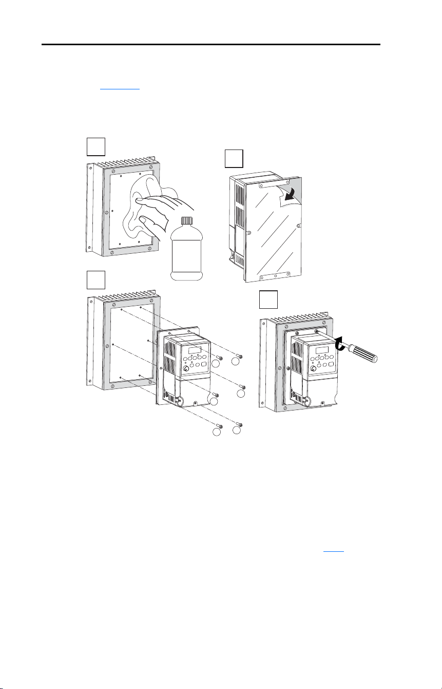
194 Rockwell Automation Publication 22D-UM001F-EN-E - September 2024
Appendix H Plate Drive Installation Instructions
Mounting Dimensions and Requirements
See Figure 13 for plate drive dimensions and mounting hole locations.
Use the pattern illustrated in Step 3 below to gradually tighten all
mounting bolts to the recommend torque of 2.0 N•m (18 lb•in).
Verification
Once the drive is mounted, a worst-case test should be run to verify the
design. The drive should run at its maximum load conditions at the
highest expected surrounding air temperature. After four hours in this
condition, measure the temperature of the drive plate. It should not
exceed 75 °C (167 °F) at its hottest point. Also, parameter b024
[Drive
Temp] should be monitored and should not exceed 80 °C (176 °F).
3
1
4
2
Isopropyl
alcohol
1
4
5
6
3
2
2.0 N•m
(18 lb•in)

Rockwell Automation Publication 22D-UM001F-EN-E - September 2024 195
Index
A
AC Supply
Ground, 16
Source, 14
Ungrounded, 14
Advanced Display Group Parameters,
108
Advanced Program Group
Parameters, 61
Ambient Temperatures, 12
Armored Cable, 21
Auto Rstrt Tries Fault, 118
Auxiliary Input Fault, 117
B
Basic Display Group Parameters, 49
Basic Program Group Parameters, 55
Before Applying Power, 43, 44
Bus Capacitors, Discharging, 9
C
Cable, Power, 20
Capacitors, Discharging, 9
CE Conformity, 40
Checklist, Start-Up, 43, 44
Circuit Breakers
Input, 17
Comm Loss Fault, 118
Command Sources for Start and
Speed, 38
Common Bus, 24
Common Symptoms and Corrective
Action, 120
Contactors, Input, 24
Control Wire, 25
Control, 2 and 3 Wire, 33, 37
Conventions, Manual, 8
Cover, Opening, 11
Cross Reference, Parameter
by Name, 112
D
Dimensions
Drive, 137
Minimum Clearances, 12
DIP Switch Locations, 26
Discharging Bus Capacitors, 9
Display, 45
Distribution Systems, Ungrounded,
14
Drive Frame Size, 8, 137
Drive Grounding, 16
Drive Overload Fault, 118
Drive Ratings, 125
DriveTools SP, 47
E
Earthing, see Grounding
EMC/RFI
Grounding, Filter, 17
Interference, 40
Enclosure Rating, Changing, 12
Encoder Interface, 29
Wire Routing, 29
Encoder Wiring, 30
Enhanced Program Group
Parameters, 95
ESD, Static Discharge, 9
F
Fault Reset and Display, 45
Faults
Auto Rstrt Tries, 118
Auxiliary Input, 117
Comm Loss, 118
Drive Overload, 118
Ground Fault, 117
Heatsink OvrTmp, 117
HW OverCurrent, 117
I/O Board Fail, 119
Motor Overload, 117
Motor Stalled, 117
OverVoltage, 117
Parameter Checksum, 119
Phase Short, 118
Phase to Ground Short, 118
Power Loss, 117

196 Rockwell Automation Publication 22D-UM001F-EN-E - September 2024
Index
Power Unit, 118
SW OverCurrent, 118
UnderVoltage, 117
Filter, RFI, 17
Frame Designations, 8, 125, 137
Fuses
Input, 17
Ratings, 125
G
General Precautions, 9
Ground Fault, 117
Grounding
Filter, 17
General, 16
H
Hardware Enable Circuitry
Enable Circuitry, 31
Heatsink OvrTmp Fault, 117
HW OverCurrent Fault, 117
I
I/O
Wiring, 24
Wiring Examples, 33, 37
I/O Board Fail Fault, 119
Input Contactor, 24
Input Fusing, 17
Input Potentiometer, 33
Input Power Conditioning, 15
Installation, 11
Integral Display, 45
Interference, EMC/RFI, 40
Internal Precharge, 24
L
LEDs, 45
M
Minimum Clearances, 12
Motor Cable Length, 22
Motor Overload, 117
Motor Overload Fault, 117
Motor Stalled Fault, 117
motor starter, 17
Mounting Options and Clearances,
12
MOVs, 14
O
Opening the Cover, 11
Operating Temperatures, 12
Operator Interface, 45
OverVoltage Fault, 117
P
Parameter
Descriptions, 47
Types, 47
Parameter Checksum Fault, 119
Parameter Cross Reference
by Name, 112
Parameters
Advanced Display Group, 108
Advanced Program Group, 61
Basic Display Group, 49
Basic Program Group, 55
Enhanced Program Group, 95
PE Ground, 16
Phase Short Fault, 118
Phase to Ground Fault, 118
Potentiometer, Wiring, 33
Power Cables/Wiring, 20
Power Conditioning, Input, 15
Power Loss Fault, 117
Power Unit Fault, 118
Powering Up the Drive, 43, 44
Precautions, General, 9
Product Selection, 131
Programming, 47
PTC Analog Input Wiring, 33
R
Ratings, 125
Reflective Wave Protection, 22
Removing Cover, 11
Repeated Start/Stop, 24
Repeated Start/Stop Precautions, 24
RFI, see EMC/RFI

Rockwell Automation Publication 22D-UM001F-EN-E - September 2024 197
Index
RWR (Reflective Wave Reducer), 22
S
Safe Off Operation, 32
Safety Ground, 16
Shielded Power Cables, 21
Short Circuit Protection, 17
Software, 47
Start and Speed Reference Selection
and Control, 38, 39
Start/Stop, Repeated, 24
Start-Up Checklist, 43, 44
Static Discharge, ESD, 9
Status LEDs, 45
Supply Source, AC, 14
SW OverCurrent Fault, 118
System Grounding, 16
T
Terminal Block
I/O, 25
Power, 24
Three Wire Control, 33, 37
Two Wire Control, 33, 37
U
UnderVoltage Fault, 117
Ungrounded Supply, 14
Unshielded Power Cables, 20
W
Watts Loss, 130
Wire
Control, 25
Wiring, 11
Block Diagram, 26, 28
Encoder, 30
I/O, 24
I/O Examples, 33, 37
Potentiometer, 33
Power, 20
PTC Example, 33

198 Rockwell Automation Publication 22D-UM001F-EN-E - September 2024
Index
Notes:

Rockwell Automation Publication 22D-UM001F-EN-E - September 2024 199
PowerFlex 40P Adjustable Frequency AC Drive User Manual
Publication 22D-UM001F-EN-E - September 2024
Supersedes Publication 22D-UM001E-EN-E - June 2017 Copyright © 2024 Rockwell Automation, Inc. All rights reserved.
Rockwell Automation Support
Use these resources to access support information.
Documentation Feedback
Your comments help us serve your documentation needs better. If you have any suggestions on how to improve our content, complete the
form at rok.auto/docfeedback.
Waste Electrical and Electronic Equipment (WEEE)
Rockwell Automation maintains current product environmental compliance information on its website at rok.auto/pec.
Technical Support Center
Find help with how-to videos, FAQs, chat, user forums, Knowledgebase, and product
notification updates.
rok.auto/support
Local Technical Support Phone Numbers Locate the telephone number for your country. rok.auto/phonesupport
Technical Documentation Center
Quickly access and download technical specifications, installation instructions, and user
manuals.
rok.auto/techdocs
Literature Library Find installation instructions, manuals, brochures, and technical data publications. rok.auto/literature
Product Compatibility and Download Center
(PCDC)
Download firmware, associated files (such as AOP, EDS, and DTM), and access product
release notes.
rok.auto/pcdc
At the end of life, this equipment should be collected separately from any unsorted municipal waste.
Rockwell Otomasyon Ticaret A.Ş. Kar Plaza İş Merkezi E Blok Kat:6 34752, İçerenköy, İstanbul, Tel: +90 (216) 5698400 EEE Yönetmeliğine Uygundur
Allen-Bradley, Connected Components Workbench, DriveTools SP, DriveExecutive, DriveGuard, expanding human possibility, PanelView, PowerFlex, Rockwell Automation, SLC, StepLogic, and
TechConnect are trademarks of Rockwell Automation, Inc.
ControlNet, DeviceNet, and EtherNet/IP are trademarks of ODVA, Inc.
Microsoft Windows is a trademark of Microsoft Corporation.
Trademarks not belonging to Rockwell Automation are property of their respective companies.