PowerFlex 520-series
Adjustable Frequency AC Drive
Bulletin Numbers 25A series B, 25B
User Manual
Original Instructions
2 Rockwell Automation Publication 520-UM001N-EN-E - July 2024
PowerFlex 520-series Adjustable Frequency AC Drive User Manual
Important User Information
Read this document and the documents listed in the additional resources section about installation, configuration, and
operation of this equipment before you install, configure, operate, or maintain this product. Users are required to familiarize
themselves with installation and wiring instructions in addition to requirements of all applicable codes, laws, and standards.
Activities including installation, adjustments, putting into service, use, assembly, disassembly, and maintenance are required to
be carried out by suitably trained personnel in accordance with applicable code of practice.
If this equipment is used in a manner not specified by the manufacturer, the protection provided by the equipment may be
impaired.
In no event will Rockwell Automation, Inc. be responsible or liable for indirect or consequential damages resulting from the use
or application of this equipment.
The examples and diagrams in this manual are included solely for illustrative purposes. Because of the many variables and
requirements associated with any particular installation, Rockwell Automation, Inc. cannot assume responsibility or liability for
actual use based on the examples and diagrams.
No patent liability is assumed by Rockwell Automation, Inc. with respect to use of information, circuits, equipment, or software
described in this manual.
Reproduction of the contents of this manual, in whole or in part, without written permission of Rockwell Automation, Inc., is
prohibited.
Throughout this manual, when necessary, we use notes to make you aware of safety considerations.
Labels may also be on or inside the equipment to provide specific precautions.
WARNING: Identifies information about practices or circumstances that can cause an explosion in a hazardous environment, which
may lead to personal injury or death, property damage, or economic loss.
ATTENTION: Identifies information about practices or circumstances that can lead to personal injury or death, property damage,
or economic loss. Attentions help you identify a hazard, avoid a hazard, and recognize the consequence.
IMPORTANT Identifies information that is critical for successful application and understanding of the product.
SHOCK HAZARD: Labels may be on or inside the equipment, for example, a drive or motor, to alert people that dangerous voltage
may be present.
BURN HAZARD: Labels may be on or inside the equipment, for example, a drive or motor, to alert people that surfaces may reach
dangerous temperatures.
ARC FLASH HAZARD: Labels may be on or inside the equipment, for example, a motor control center, to alert people to potential Arc
Flash. Arc Flash will cause severe injury or death. Wear proper Personal Protective Equipment (PPE). Follow ALL Regulatory
requirements for safe work practices and for Personal Protective Equipment (PPE).

Rockwell Automation Publication 520-UM001N-EN-E - July 2024 3
Table of Contents
Preface . . . . . . . . . . . . . . . . . . . . . . . . . . . . . . . . . . . . . . . . . . . . . . . . . . . . . . . 9
About This Publication . . . . . . . . . . . . . . . . . . . . . . . . . . . . . . . . . . . . . . . . . . . 9
Download Firmware, AOP, EDS, and Other Files . . . . . . . . . . . . . . . . . . . . 9
Summary of Changes. . . . . . . . . . . . . . . . . . . . . . . . . . . . . . . . . . . . . . . . . . . . . 9
Who Should Use this Manual. . . . . . . . . . . . . . . . . . . . . . . . . . . . . . . . . . . . . . 9
Additional Resources . . . . . . . . . . . . . . . . . . . . . . . . . . . . . . . . . . . . . . . . . . . . 10
Download Files . . . . . . . . . . . . . . . . . . . . . . . . . . . . . . . . . . . . . . . . . . . . . . . . . 11
Manual Conventions . . . . . . . . . . . . . . . . . . . . . . . . . . . . . . . . . . . . . . . . . . . . 12
Drive Frame Sizes. . . . . . . . . . . . . . . . . . . . . . . . . . . . . . . . . . . . . . . . . . . . . . . 12
General Precautions. . . . . . . . . . . . . . . . . . . . . . . . . . . . . . . . . . . . . . . . . . . . . 13
Catalog Number Explanation . . . . . . . . . . . . . . . . . . . . . . . . . . . . . . . . . 14
Chapter 1
Installation/Wiring Mounting Considerations . . . . . . . . . . . . . . . . . . . . . . . . . . . . . . . . . . . . . . . 15
Minimum Mounting Clearances . . . . . . . . . . . . . . . . . . . . . . . . . . . . . . 15
Ambient Operating Temperatures. . . . . . . . . . . . . . . . . . . . . . . . . . . . . 17
Current Derating Curves . . . . . . . . . . . . . . . . . . . . . . . . . . . . . . . . . . . . . 17
Debris Protection. . . . . . . . . . . . . . . . . . . . . . . . . . . . . . . . . . . . . . . . . . . . 18
Storage . . . . . . . . . . . . . . . . . . . . . . . . . . . . . . . . . . . . . . . . . . . . . . . . . . . . . 18
AC Supply Source Considerations . . . . . . . . . . . . . . . . . . . . . . . . . . . . . . . . 19
Ungrounded Distribution Systems . . . . . . . . . . . . . . . . . . . . . . . . . . . . 19
Input Power Conditioning. . . . . . . . . . . . . . . . . . . . . . . . . . . . . . . . . . . . 20
General Grounding Requirements . . . . . . . . . . . . . . . . . . . . . . . . . . . . . . . . 20
Ground Fault Monitoring . . . . . . . . . . . . . . . . . . . . . . . . . . . . . . . . . . . . 21
Safety Ground - (PE) . . . . . . . . . . . . . . . . . . . . . . . . . . . . . . . . . . . . . . . . . 21
Network Ground . . . . . . . . . . . . . . . . . . . . . . . . . . . . . . . . . . . . . . . . . . . . 21
Motor Ground. . . . . . . . . . . . . . . . . . . . . . . . . . . . . . . . . . . . . . . . . . . . . . . 21
Shield Termination - SHLD. . . . . . . . . . . . . . . . . . . . . . . . . . . . . . . . . . . 21
RFI Filter Grounding. . . . . . . . . . . . . . . . . . . . . . . . . . . . . . . . . . . . . . . . . 22
Fuses and Circuit Breakers. . . . . . . . . . . . . . . . . . . . . . . . . . . . . . . . . . . . . . . 22
Fusing. . . . . . . . . . . . . . . . . . . . . . . . . . . . . . . . . . . . . . . . . . . . . . . . . . . . . . 22
Circuit Breakers . . . . . . . . . . . . . . . . . . . . . . . . . . . . . . . . . . . . . . . . . . . . . 22
Fuses and Circuit Breakers for PowerFlex 520-series Drives. . . . . . 23
Power and Control Module. . . . . . . . . . . . . . . . . . . . . . . . . . . . . . . . . . . . . . . 29
Control Module Cover . . . . . . . . . . . . . . . . . . . . . . . . . . . . . . . . . . . . . . . . . . . 31
Power Module Terminal Guard . . . . . . . . . . . . . . . . . . . . . . . . . . . . . . . . . . . 32
Power Wiring. . . . . . . . . . . . . . . . . . . . . . . . . . . . . . . . . . . . . . . . . . . . . . . . . . . 33
Motor Cable Types Acceptable for 100…600 Volt Installations . . . . 33
Reflected Wave Protection. . . . . . . . . . . . . . . . . . . . . . . . . . . . . . . . . . . . 35
Output Disconnect . . . . . . . . . . . . . . . . . . . . . . . . . . . . . . . . . . . . . . . . . . 35
Power Terminal Block . . . . . . . . . . . . . . . . . . . . . . . . . . . . . . . . . . . . . . . . . . . 36
Common Bus/Precharge Notes . . . . . . . . . . . . . . . . . . . . . . . . . . . . . . . . . . . 36
I/O Wiring . . . . . . . . . . . . . . . . . . . . . . . . . . . . . . . . . . . . . . . . . . . . . . . . . . . . . 37
Motor Start/Stop Precautions. . . . . . . . . . . . . . . . . . . . . . . . . . . . . . . . . 37
Signal and Control Wire Types. . . . . . . . . . . . . . . . . . . . . . . . . . . . . . . . 37
Maximum Control Wire Recommendations. . . . . . . . . . . . . . . . . . . . 38

4 Rockwell Automation Publication 520-UM001N-EN-E - July 2024
Table of Contents
Control I/O Terminal Block . . . . . . . . . . . . . . . . . . . . . . . . . . . . . . . . . . . . . . 38
PowerFlex 523 Control I/O Terminal Block . . . . . . . . . . . . . . . . . . . . . 38
PowerFlex 525 Control I/O Terminal Block . . . . . . . . . . . . . . . . . . . . . 42
I/O Wiring Examples . . . . . . . . . . . . . . . . . . . . . . . . . . . . . . . . . . . . . . . . 44
Start and Speed Reference Control . . . . . . . . . . . . . . . . . . . . . . . . . . . . . . . 49
Start Source and Speed Reference Selection. . . . . . . . . . . . . . . . . . . . 49
Accel/Decel Selection . . . . . . . . . . . . . . . . . . . . . . . . . . . . . . . . . . . . . . . . 51
CE Conformity . . . . . . . . . . . . . . . . . . . . . . . . . . . . . . . . . . . . . . . . . . . . . . . . . 52
Low Voltage Directive (2014/35/EU). . . . . . . . . . . . . . . . . . . . . . . . . . . . 52
EMC Directive (2014/30/EU) . . . . . . . . . . . . . . . . . . . . . . . . . . . . . . . . . . 52
Machinery Directive (2006/42/EC) . . . . . . . . . . . . . . . . . . . . . . . . . . . . 52
ATEX Directive (2014/34/EU) . . . . . . . . . . . . . . . . . . . . . . . . . . . . . . . . . 52
UKCA Conformity. . . . . . . . . . . . . . . . . . . . . . . . . . . . . . . . . . . . . . . . . . . . . . . 52
Electrical Equipment (Safety) Regulations (2016 No. 1101) . . . . . . . 53
Electromagnetic Compatibility Regulations (2016 No. 1091). . . . . . 53
Supply of Machinery (Safety) Regulations (2008 No. 1597) . . . . . . . 53
Equipment and Protective Systems Intended for Use in Potentially
Explosive Atmospheres Regulations (2016 No. 1107) . . . . . . . . . . . . . 53
General Considerations . . . . . . . . . . . . . . . . . . . . . . . . . . . . . . . . . . . . . . 53
Chapter 2
Startup Prepare for Drive Startup . . . . . . . . . . . . . . . . . . . . . . . . . . . . . . . . . . . . . . . . 59
Drive Startup Task List . . . . . . . . . . . . . . . . . . . . . . . . . . . . . . . . . . . . . . . 59
Start, Stop, Direction, and Speed Control . . . . . . . . . . . . . . . . . . . . . . 60
Variable Torque Fan/Pump Applications . . . . . . . . . . . . . . . . . . . . . . . 61
Display and Control Keys . . . . . . . . . . . . . . . . . . . . . . . . . . . . . . . . . . . . . . . . 61
Control and Navigation Keys . . . . . . . . . . . . . . . . . . . . . . . . . . . . . . . . . 62
Viewing and Editing Parameters . . . . . . . . . . . . . . . . . . . . . . . . . . . . . . . . . 63
Drive Programming Tools . . . . . . . . . . . . . . . . . . . . . . . . . . . . . . . . . . . . . . . 64
Language Support . . . . . . . . . . . . . . . . . . . . . . . . . . . . . . . . . . . . . . . . . . . . . . 64
Smart Startup with Basic Program Group Parameters . . . . . . . . . . . . . . 65
LCD Display with QuickView Technology . . . . . . . . . . . . . . . . . . . . . . . . . 67
Using the USB Port. . . . . . . . . . . . . . . . . . . . . . . . . . . . . . . . . . . . . . . . . . . . . . 67
MainsFree Programming. . . . . . . . . . . . . . . . . . . . . . . . . . . . . . . . . . . . . 67
Using Drive Startup in CCW or Logix Designer Application . . . . . . . . . 68
Chapter 3
Programming and Parameters About Parameters . . . . . . . . . . . . . . . . . . . . . . . . . . . . . . . . . . . . . . . . . . . . . . . 71
Parameter Groups . . . . . . . . . . . . . . . . . . . . . . . . . . . . . . . . . . . . . . . . . . . . . . 73
AppView Parameter Groups . . . . . . . . . . . . . . . . . . . . . . . . . . . . . . . . . . 76
CustomView Parameter Group. . . . . . . . . . . . . . . . . . . . . . . . . . . . . . . . 77
Basic Display Group. . . . . . . . . . . . . . . . . . . . . . . . . . . . . . . . . . . . . . . . . . . . . 78
Basic Program Group. . . . . . . . . . . . . . . . . . . . . . . . . . . . . . . . . . . . . . . . . . . . 84
Terminal Block Group . . . . . . . . . . . . . . . . . . . . . . . . . . . . . . . . . . . . . . . . . . . 90
Communications Group . . . . . . . . . . . . . . . . . . . . . . . . . . . . . . . . . . . . . . . . 102
Logic Group . . . . . . . . . . . . . . . . . . . . . . . . . . . . . . . . . . . . . . . . . . . . . . . . . . . 108
Advanced Display Group. . . . . . . . . . . . . . . . . . . . . . . . . . . . . . . . . . . . . . . . . 111
Advanced Program Group . . . . . . . . . . . . . . . . . . . . . . . . . . . . . . . . . . . . . . 116
Network Parameter Group. . . . . . . . . . . . . . . . . . . . . . . . . . . . . . . . . . . . . . 144

Rockwell Automation Publication 520-UM001N-EN-E - July 2024 5
Table of Contents
Modified Parameter Group . . . . . . . . . . . . . . . . . . . . . . . . . . . . . . . . . . . . . 144
Fault and Diagnostic Group . . . . . . . . . . . . . . . . . . . . . . . . . . . . . . . . . . . . . 144
AppView Parameter Groups. . . . . . . . . . . . . . . . . . . . . . . . . . . . . . . . . . . . . 152
CustomView Parameter Group . . . . . . . . . . . . . . . . . . . . . . . . . . . . . . . . . . 153
Parameter Cross-reference by Name . . . . . . . . . . . . . . . . . . . . . . . . . . . . . 154
Chapter 4
Troubleshooting Drive Status . . . . . . . . . . . . . . . . . . . . . . . . . . . . . . . . . . . . . . . . . . . . . . . . . . . 159
Faults . . . . . . . . . . . . . . . . . . . . . . . . . . . . . . . . . . . . . . . . . . . . . . . . . . . . . . . . . 159
Fault Indication . . . . . . . . . . . . . . . . . . . . . . . . . . . . . . . . . . . . . . . . . . . . 160
Manually Clearing Faults . . . . . . . . . . . . . . . . . . . . . . . . . . . . . . . . . . . . 160
Automatically Clearing Faults. . . . . . . . . . . . . . . . . . . . . . . . . . . . . . . . 160
Auto Restart (Reset/Run) . . . . . . . . . . . . . . . . . . . . . . . . . . . . . . . . . . . . 160
Fault Descriptions . . . . . . . . . . . . . . . . . . . . . . . . . . . . . . . . . . . . . . . . . . . . . 161
Common Symptoms and Corrective Actions. . . . . . . . . . . . . . . . . . . . . . 164
Appendix A
Supplemental Drive Information Certifications. . . . . . . . . . . . . . . . . . . . . . . . . . . . . . . . . . . . . . . . . . . . . . . . . . 167
Environmental Specifications . . . . . . . . . . . . . . . . . . . . . . . . . . . . . . . . . . . 168
Technical Specifications . . . . . . . . . . . . . . . . . . . . . . . . . . . . . . . . . . . . . . . . 169
Power Specifications . . . . . . . . . . . . . . . . . . . . . . . . . . . . . . . . . . . . . . . . . . . 171
Appendix B
Accessories and Dimensions Product Selection . . . . . . . . . . . . . . . . . . . . . . . . . . . . . . . . . . . . . . . . . . . . . . 175
Product Dimensions . . . . . . . . . . . . . . . . . . . . . . . . . . . . . . . . . . . . . . . . . . . 187
Adapter Plate Dimensions . . . . . . . . . . . . . . . . . . . . . . . . . . . . . . . . . . . 199
Optional Accessories and Kits . . . . . . . . . . . . . . . . . . . . . . . . . . . . . . . . . . . 202
Installing a Communication Adapter . . . . . . . . . . . . . . . . . . . . . . . . . 202
Removing a Communication Adapter . . . . . . . . . . . . . . . . . . . . . . . . 203
Appendix C
RS-485 (DSI) Protocol Network Wiring . . . . . . . . . . . . . . . . . . . . . . . . . . . . . . . . . . . . . . . . . . . . . . . 205
Parameter Configuration . . . . . . . . . . . . . . . . . . . . . . . . . . . . . . . . . . . . . . . 206
Supported Modbus Function Codes. . . . . . . . . . . . . . . . . . . . . . . . . . . . . . 207
Writing (06) Logic Command Data . . . . . . . . . . . . . . . . . . . . . . . . . . . . . . 207
Writing (06) Comm Frequency Command. . . . . . . . . . . . . . . . . . . . . . . . 209
Reading (03) Logic Status Data . . . . . . . . . . . . . . . . . . . . . . . . . . . . . . . . . . 210
Reading (03) Drive Error Codes . . . . . . . . . . . . . . . . . . . . . . . . . . . . . . . . . 211
Reading (03) Drive Operational Values . . . . . . . . . . . . . . . . . . . . . . . . . . . 212
Reading (03) and Writing (06) Drive Parameters . . . . . . . . . . . . . . . . . . 212
Additional Information. . . . . . . . . . . . . . . . . . . . . . . . . . . . . . . . . . . . . . . . . 212
Appendix D
Velocity StepLogic, Basic Logic,
and Timer/Counter Functions
Velocity StepLogic Using Timed Steps . . . . . . . . . . . . . . . . . . . . . . . . . . . 214
Velocity StepLogic Sequence. . . . . . . . . . . . . . . . . . . . . . . . . . . . . . . . . 214
Velocity StepLogic Using Basic Logic Functions . . . . . . . . . . . . . . . . . . . 214
Timer Function . . . . . . . . . . . . . . . . . . . . . . . . . . . . . . . . . . . . . . . . . . . . . . . . 215

6 Rockwell Automation Publication 520-UM001N-EN-E - July 2024
Table of Contents
Counter Function . . . . . . . . . . . . . . . . . . . . . . . . . . . . . . . . . . . . . . . . . . . . . . 216
Velocity StepLogic Parameters . . . . . . . . . . . . . . . . . . . . . . . . . . . . . . . . . . 217
Appendix E
Encoder/Pulse Train Usage and
Position StepLogic Application
Encoder and Pulse Train Usage. . . . . . . . . . . . . . . . . . . . . . . . . . . . . . . . . . 219
Encoder Interface . . . . . . . . . . . . . . . . . . . . . . . . . . . . . . . . . . . . . . . . . . 219
HTL/TTL DIP Switches . . . . . . . . . . . . . . . . . . . . . . . . . . . . . . . . . . . . . . 220
Wiring Notes . . . . . . . . . . . . . . . . . . . . . . . . . . . . . . . . . . . . . . . . . . . . . . . . . . 221
Determine Encoder Pulse Per Revolution (PPR) Specification Based on
Speed Resolution . . . . . . . . . . . . . . . . . . . . . . . . . . . . . . . . . . . . . . . . . . . . . . 221
Positioning Overview. . . . . . . . . . . . . . . . . . . . . . . . . . . . . . . . . . . . . . . . . . . 222
Common Guidelines for All Applications . . . . . . . . . . . . . . . . . . . . . . . . . 222
Positioning Operation . . . . . . . . . . . . . . . . . . . . . . . . . . . . . . . . . . . . . . . . . . 223
Homing Routine . . . . . . . . . . . . . . . . . . . . . . . . . . . . . . . . . . . . . . . . . . . . . . . 226
Encoder and Position Feedback . . . . . . . . . . . . . . . . . . . . . . . . . . . . . . . . . 227
Use Over Communications . . . . . . . . . . . . . . . . . . . . . . . . . . . . . . . . . . . . . 228
Setup Notes . . . . . . . . . . . . . . . . . . . . . . . . . . . . . . . . . . . . . . . . . . . . . . . . . . . 229
Appendix F
PID Set Up PID Loop . . . . . . . . . . . . . . . . . . . . . . . . . . . . . . . . . . . . . . . . . . . . . . . . . . . . . . 231
Exclusive Control. . . . . . . . . . . . . . . . . . . . . . . . . . . . . . . . . . . . . . . . . . . 231
Trim Control . . . . . . . . . . . . . . . . . . . . . . . . . . . . . . . . . . . . . . . . . . . . . . . 232
PID Reference and Feedback . . . . . . . . . . . . . . . . . . . . . . . . . . . . . . . . . . . . 233
Analog PID Reference Signals . . . . . . . . . . . . . . . . . . . . . . . . . . . . . . . . . . . 234
Scale Function . . . . . . . . . . . . . . . . . . . . . . . . . . . . . . . . . . . . . . . . . . . . . 234
Invert Function. . . . . . . . . . . . . . . . . . . . . . . . . . . . . . . . . . . . . . . . . . . . . 234
PID Deadband . . . . . . . . . . . . . . . . . . . . . . . . . . . . . . . . . . . . . . . . . . . . . 234
PID Preload . . . . . . . . . . . . . . . . . . . . . . . . . . . . . . . . . . . . . . . . . . . . . . . . 235
PID Limits . . . . . . . . . . . . . . . . . . . . . . . . . . . . . . . . . . . . . . . . . . . . . . . . . 235
PID Gains. . . . . . . . . . . . . . . . . . . . . . . . . . . . . . . . . . . . . . . . . . . . . . . . . . 235
Guidelines for Adjusting the PID Gains . . . . . . . . . . . . . . . . . . . . . . . 236
Appendix G
Safe Torque Off Function PowerFlex 525 Safe Torque Off Overview . . . . . . . . . . . . . . . . . . . . . . . . . 239
EC Type Examination Certification . . . . . . . . . . . . . . . . . . . . . . . . . . . . . . 239
UK Type Examination Certification. . . . . . . . . . . . . . . . . . . . . . . . . . . . . . 240
EMC Instructions . . . . . . . . . . . . . . . . . . . . . . . . . . . . . . . . . . . . . . . . . . . . . . 240
Using PowerFlex 525 Safe Torque Off . . . . . . . . . . . . . . . . . . . . . . . . . . . . 240
Safety Concept. . . . . . . . . . . . . . . . . . . . . . . . . . . . . . . . . . . . . . . . . . . . . . . . . 241
Important Safety Considerations . . . . . . . . . . . . . . . . . . . . . . . . . . . . 241
Functional Proof Test . . . . . . . . . . . . . . . . . . . . . . . . . . . . . . . . . . . . . . . 242
PFD and PFH Data. . . . . . . . . . . . . . . . . . . . . . . . . . . . . . . . . . . . . . . . . . 242
Safety Reaction Time . . . . . . . . . . . . . . . . . . . . . . . . . . . . . . . . . . . . . . . 242
Enabling PowerFlex 525 Safe Torque Off . . . . . . . . . . . . . . . . . . . . . . . . . 243
Wiring . . . . . . . . . . . . . . . . . . . . . . . . . . . . . . . . . . . . . . . . . . . . . . . . . . . . . . . . 243
PowerFlex 525 Safe Torque Off Operation . . . . . . . . . . . . . . . . . . . . . . . . 243
Verify Operation . . . . . . . . . . . . . . . . . . . . . . . . . . . . . . . . . . . . . . . . . . . . . . . 244
Discrepancy Time of the Safety Inputs. . . . . . . . . . . . . . . . . . . . . . . . 244

Rockwell Automation Publication 520-UM001N-EN-E - July 2024 7
Table of Contents
Connection Examples . . . . . . . . . . . . . . . . . . . . . . . . . . . . . . . . . . . . . . . . . . 245
Example 1 – Safe Torque Off Connection with Coast-to-Stop Action,
SIL 2/PLd . . . . . . . . . . . . . . . . . . . . . . . . . . . . . . . . . . . . . . . . . . . . . . . . . . 245
Example 2 – Safe Torque Off Connection with Controlled Stop
Action, SIL 2/PLd . . . . . . . . . . . . . . . . . . . . . . . . . . . . . . . . . . . . . . . . . . . 247
Example 3 – Safe Torque Off Connection with Coast-to-Stop Action
Using External +24V supply, SIL 3/PL e . . . . . . . . . . . . . . . . . . . . . . . 248
PowerFlex 525 Certification for Safe Torque Off. . . . . . . . . . . . . . . . . . . 248
Appendix H
EtherNet/IP Establishing A Connection With EtherNet/IP. . . . . . . . . . . . . . . . . . . . . 249
Ground Connections for EtherNet/IP Networks . . . . . . . . . . . . . . . . . . 250
Appendix I
Control Diagrams Induction Motor Tuning Diagrams . . . . . . . . . . . . . . . . . . . . . . . . . . . . . . 251
Adjusting Speed Control Parameters. . . . . . . . . . . . . . . . . . . . . . . . . . . . . 252
Appendix J
PowerFlex 525 PM Motor
Configuration
Motor Control. . . . . . . . . . . . . . . . . . . . . . . . . . . . . . . . . . . . . . . . . . . . . . 254
Motor Data . . . . . . . . . . . . . . . . . . . . . . . . . . . . . . . . . . . . . . . . . . . . . . . . 254
Feedback . . . . . . . . . . . . . . . . . . . . . . . . . . . . . . . . . . . . . . . . . . . . . . . . . . 255
Stop Mode/Brake Type . . . . . . . . . . . . . . . . . . . . . . . . . . . . . . . . . . . . . . 255
Direction Test . . . . . . . . . . . . . . . . . . . . . . . . . . . . . . . . . . . . . . . . . . . . . . 256
Auto Tune. . . . . . . . . . . . . . . . . . . . . . . . . . . . . . . . . . . . . . . . . . . . . . . . . . 256
Manual Configuration Using Drive Keypad. . . . . . . . . . . . . . . . . . . . . . . 258
Additional PM Motor Configuration . . . . . . . . . . . . . . . . . . . . . . . . . . . . . 259
Additional Setup for Open Loop PM Motor. . . . . . . . . . . . . . . . . . . . 259
Additional Setup for Closed Loop PM Motor. . . . . . . . . . . . . . . . . . . 261
Optional Parameter Adjustments for Optimum Performance . . . . . . 263
Appendix K
PowerFlex 525 Synchronous
Reluctance Motor Configuration
SynRM Structure . . . . . . . . . . . . . . . . . . . . . . . . . . . . . . . . . . . . . . . . . . . . . . 265
Control Diagram . . . . . . . . . . . . . . . . . . . . . . . . . . . . . . . . . . . . . . . . . . . 265
SynRM Control Configuration . . . . . . . . . . . . . . . . . . . . . . . . . . . . . . . . . . 266
Index . . . . . . . . . . . . . . . . . . . . . . . . . . . . . . . . . . . . . . . . . . . . . . . . . . . . . . . . . 269

8 Rockwell Automation Publication 520-UM001N-EN-E - July 2024
Table of Contents
Notes:

Rockwell Automation Publication 520-UM001N-EN-E - July 2024 9
Preface
About This Publication
The purpose of this manual is to provide you with the basic information that is
needed to install, startup, and troubleshoot the PowerFlex® 520-series
adjustable frequency AC drive.
Rockwell Automation recognizes that some of the terms that are currently
used in our industry and in this publication are not in alignment with the
movement toward inclusive language in technology. We are proactively
collaborating with industry peers to find alternatives to such terms and
making changes to our products and content. Please excuse the use of such
terms in our content while we implement these changes.
Download Firmware, AOP,
EDS, and Other Files
Download firmware, associated files (such as AOP, EDS, and DTM), and access
product release notes from the Product Compatibility and Download Center at
rok.auto/pcdc
.
See Download Files on page 11
to download the files for your PowerFlex 525
drive.
Summary of Changes
This publication contains the following new or updated information. This list
includes substantive updates only and is not intended to reflect all changes.
Who Should Use this Manual
This manual is intended for qualified personnel. You must be able to program
and operate Adjustable Frequency AC Drive devices. In addition, you must
have an understanding of the parameter settings and functions.
Topic Page
Updated Additional Resources 10
Updated section Circuit Breakers 22
Updated section Bulletin 140M/140MT (Self-protected Combination Controller)/UL489 Circuit
Breakers
23
Updated Fuses and Circuit Breakers for PowerFlex 520-series Drives 23…28
Updated Installation Requirements Related to EN 61800-5-1 and the Low Voltage Directive/UK
LV Regulations
54
Updated Certifications 167
Updated Dynamic Brake Resistors 176
Updated Programming Software 185
10 Rockwell Automation Publication 520-UM001N-EN-E - July 2024
Preface
Additional Resources
These documents contain additional information concerning related products
from Rockwell Automation. You can view or download publications at
rok.auto/literature
.
Resource Description
PowerFlex 520-series AC Drive Specifications Technical
Data, publication 520-TD001
Describes how to configure, use, and troubleshoot
PowerFlex 520-series drives.
PowerFlex 4-class HIM (DSI) Quick Reference,
publication 22HIM-QR001
Provides descriptions and information on PowerFlex
4-class human interface modules (HIM).
PowerFlex 525 Embedded EtherNet/IP Adapter User
Manual, publication 520COM-UM001
Describes how to use the embedded EtherNet/IP
adapter on the PowerFlex 525 drive for network
communication.
PowerFlex 525 DeviceNet Adapter User Manual,
publication 520COM-UM002
Describes how to use the DeviceNet adapter for
PowerFlex 520-series drives for network
communication.
PowerFlex 25-COMM-E2P Dual-port EtherNet/IP Adapter
User Manual, publication 520COM-UM003
Describes how to use the dual-port EtherNet/IP adapter
for PowerFlex 520-series drives for network
communication.
PowerFlex 25-COMM-P PROFIBUS DPV1 Adapter User
Manual, publication 520COM-UM004
Describes how to use the PROFIBUS DPV1 adapter for
PowerFlex 520-series drives for network
communication.
PowerFlex 520-series PROFINET Adapter User Manual,
publication 520COM-UM005
Describes how to use the PROFINET adapter for
PowerFlex 520-series drives for network
communication.
PowerFlex Dynamic Braking Resistor Calculator
Application Technique, publication PFLEX-AT001
Provides information on dynamic braking and how to
determine dynamic braking requirements.
Drives in Common Bus Configurations Application
Technique, publication DRIVES-AT002
Provide the necessary guidelines, considerations, and
limitations for the proper application of PowerFlex
drives used in common bus configurations.
Wiring and Grounding for Pulse Width Modulated (PWM)
AC Drives Installation Instructions,
publication DRIVES-IN001
Describes how to install, protect, wire, and ground
pulse-width modulated AC drives.
Preventive Maintenance Checklist of Industrial Control
and Drive System Equipment Service Bulletin,
publication DRIVES-TD001
Provides a checklist and guidelines for performing
preventive maintenance.
EtherNet/IP Network Devices User Manual,
publication ENET-UM006
Describes how to configure and use EtherNet/IP devices
to communicate on the EtherNet/IP network.
Ethernet Reference Manual, publication ENET-RM002
Describes basic Ethernet concepts, infrastructure
components, and infrastructure features.
Safety Guidelines for the Application, Installation, and
Maintenance of Solid-state Control, publication SGI-1.1
Designed to harmonize with NEMA Standards Publication
No. ICS 1.1-1987 and provides general guidelines for the
application, installation, and maintenance of solid-state
control in the form of individual devices or packaged
assemblies incorporating solid-state components.
Industrial Automation Wiring and Grounding Guidelines,
publication 1770-4.1
Provides general guidelines for installing a Rockwell
Automation industrial system.
Product Selection and Configuration tools,
rok.auto/systemtools
Helps configure complete, valid catalog numbers and
build complete quotes based on detailed product
information.
Rockwell Automation Global Short-circuit Current
Ratings (SCCR) tool, rok.auto/sccr
Provides coordinated high-fault branch circuit solutions
for motor starters, soft starters, and component drives.
Product Certifications website, rok.auto/certifications
Provides declarations of conformity, certificates, and
other certification details.
Rockwell Automation Publication 520-UM001N-EN-E - July 2024 11
Preface
Download Files
Follow these steps to download the files for your PowerFlex 525 drive.
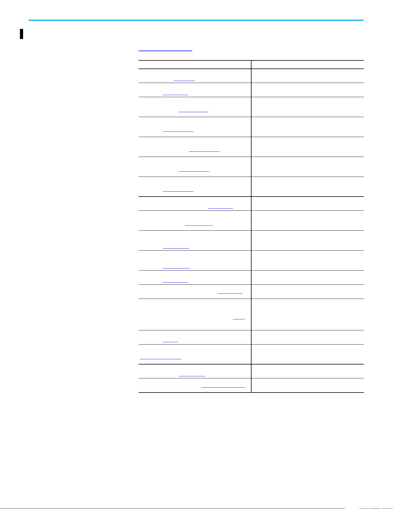
1. Go to the Rockwell Automation Product Compatibility and Download
Center at rok.auto/pcdc
.
2. Click the Find Downloads link.
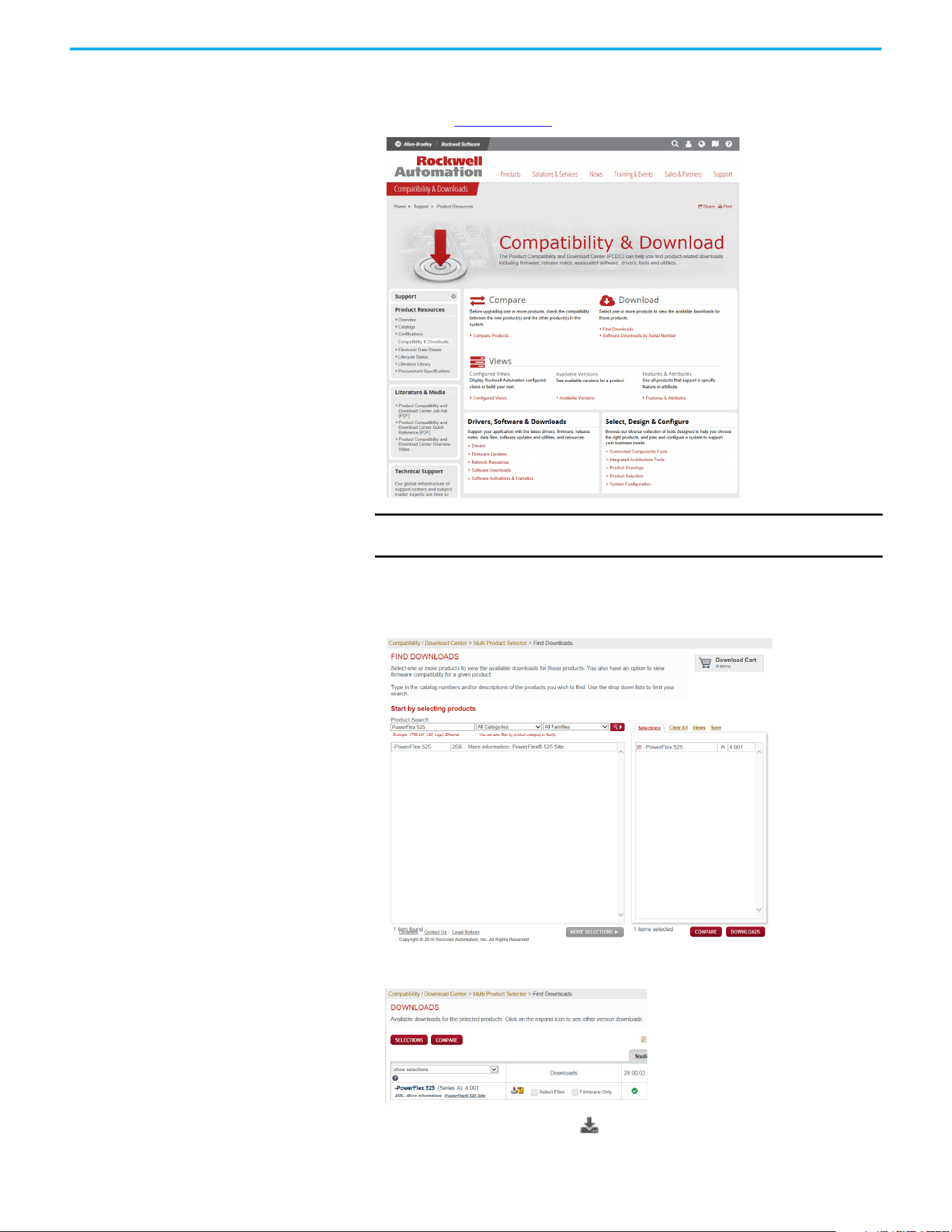
3. Enter “PowerFlex 525” into the Product Search field.
The results appear in the box below.
4. Select the entry and the firmware revision, then click Downloads.
5. Click the Show Downloads icon, then click the links to download
the firmware revision and AOP files to your computer.
IMPORTANT You must sign in to the Rockwell Automation website before
downloading a firmware revision.
12 Rockwell Automation Publication 520-UM001N-EN-E - July 2024
Preface
Manual Conventions
• In this manual we refer to PowerFlex 520-series adjustable frequency
AC drive as; drive, PowerFlex 520-series, PowerFlex 520-series drive or
PowerFlex 520-series AC drive.
• Specific drives within the PowerFlex 520-series may be referred to as:
– PowerFlex 523, PowerFlex 523 drive or PowerFlex 523 AC drive.
– PowerFlex 525, PowerFlex 525 drive or PowerFlex 525 AC drive.
• Parameter numbers and names are shown in this format:
• The following words are used throughout the manual to describe an
action:
• The Studio 5000® Engineering and Design Environment combines
engineering and design elements into a common environment. The
first element in the Studio 5000 environment is the Logix Designer
application. The Studio 5000 Logix Designer® application is the
rebranding of RSLogix 5000® software and will continue to be the
product to program Logix 5000® controllers for discrete, process,
batch, motion, safety, and drive-based solutions. The Studio 5000
environment is the foundation for the future of Rockwell Automation®
engineering design tools and capabilities. It is the one place for design
engineers to develop all elements of their control system.
Drive Frame Sizes
Similar PowerFlex 520-series drive sizes are grouped into frame sizes to
simplify spare parts ordering, dimensioning, and so on. A cross-reference of
drive catalog numbers and their respective frame sizes is provided in
Appendix B
.
P 031 [Motor NP Volts]
Name
Number
Group
b
P
t
C
L
d
A
N
M
f
G
= Basic Display
= Basic Program
= Terminal Blocks
= Communications
= Logic
= Advanced Display
= Advanced Program
= Network
= Modified
= Fault and Diagnostic
= AppView and CustomView
Words Meaning
Can Possible, able to do something
Cannot Not possible, not able to do something
May Permitted, allowed
Must Unavoidable, you must do this
Shall Required and necessary
Should Recommended
Should Not Not Recommended

Rockwell Automation Publication 520-UM001N-EN-E - July 2024 13
Preface
General Precautions
ATTENTION: The drive contains high-voltage capacitors, which take time to
discharge after removal of mains supply. After power has been removed
from the drive, wait three minutes to make sure DC bus capacitors are
discharged. After three minutes, verify AC voltage L1, L2, L3 (Line to Line and
Line to Ground) to ensure mains power has been disconnected. Measure DC
voltage across DC- and DC+ bus terminals to verify DC Bus has discharged
to zero volts. Measure DC voltage from L1, L2, L3, T1, T2, T3 DC – and DC+
terminals to ground and keep the meter on the terminals until the voltage
discharges to zero volts. The discharge process may take several minutes
to reach zero volts.
Darkened display LEDs are not an indication that capacitors have
discharged to safe voltage levels.
ATTENTION: Only qualified personnel familiar with adjustable frequency AC
drives and associated machinery should plan or implement the installation,
startup and subsequent maintenance of the system. Failure to comply may
result in personal injury and/or equipment damage.
ATTENTION: This drive contains ESD (Electrostatic Discharge) sensitive
parts and assemblies. Static control precautions are required when
installing, testing, servicing, or repairing this assembly. Component damage
may result if ESD control procedures are not followed. If you are not familiar
with static control procedures, reference Allen-Bradley® publication
8000-4.5.2
, “Guarding Against Electrostatic Damage” or any other applicable
ESD protection handbook.
ATTENTION: An incorrectly applied or installed drive can result in
component damage or a reduction in product life. Wiring or application
errors, such as undersizing the motor, incorrect or inadequate AC supply, or
excessive ambient temperatures may result in malfunction of the system.
ATTENTION: The bus regulator function is extremely useful for preventing
nuisance overvoltage faults resulting from aggressive decelerations,
overhauling loads, and eccentric loads. However, it can also cause either of
the following two conditions to occur.
1. Fast positive changes in input voltage or imbalanced input voltages can
cause uncommanded positive speed changes.
2. Actual deceleration times can be longer than commanded deceleration
times.
However, a “Stall Fault” is generated if the drive remains in this state for one
minute. If this condition is unacceptable, the bus regulator must be
disabled (see parameter A550 [Bus Reg Enable]). In addition, installing a
properly sized dynamic brake resistor will provide proper stopping
requirements based on braking resistor sizing.
ATTENTION: Risk of injury or equipment damage exists. Drive does not
contain user-serviceable components. Do not disassemble drive chassis.
14 Rockwell Automation Publication 520-UM001N-EN-E - July 2024
Preface
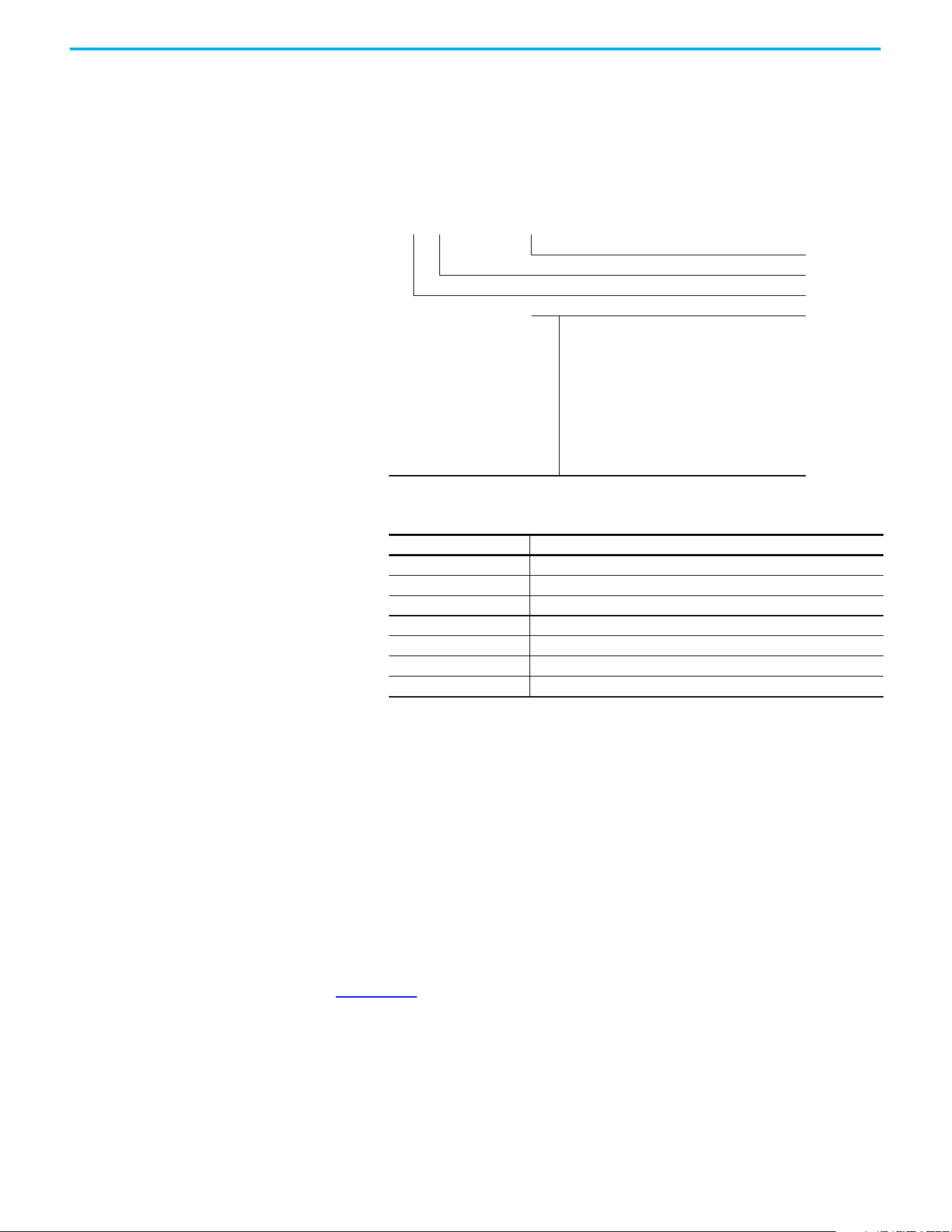
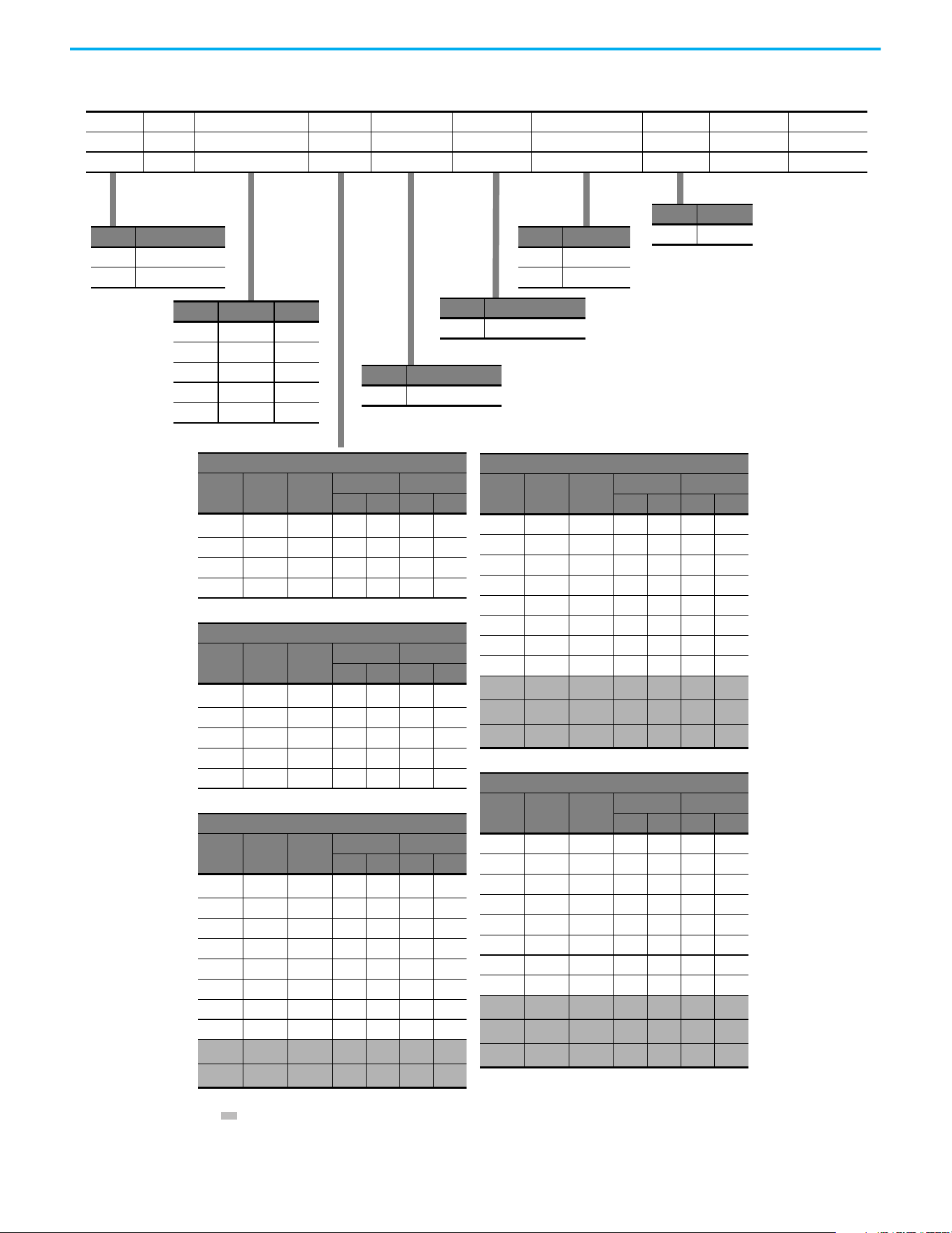
Catalog Number Explanation
Code Type
25A PowerFlex 523
25B PowerFlex 525
1…3 4 5 6…8 9 10 11 12 13 14
25B – B 2P3 N 1 1 4 – –
Drive Dash Voltage Rating Rating Enclosure Reserved Emission Class Reserved Dash Dash
Output Current @ 1-phase, 100...120V Input
Code Amps Frame
ND HD
HP kW HP kW
1P6
(1)
1.6 A 0.25 0.2 0.25 0.2
2P5 2.5 A 0.5 0.4 0.5 0.4
4P8 4.8 B 1.0 0.75 1.0 0.75
6P0 6.0 B 1.5 1.1 1.5 1.1
Output Current @ 1-phase, 200...240V Input
Code Amps Frame
ND HD
HP kW HP kW
1P6
(1)
1.6 A 0.25 0.2 0.25 0.2
2P5 2.5 A 0.5 0.4 0.5 0.4
4P8 4.8 A 1.0 0.75 1.0 0.75
8P0 8.0 B 2.0 1.5 2.0 1.5
011 11.0 B 3.0 2.2 3.0 2.2
Output Current @ 3-phase, 200...240V Input
Code Amps Frame
ND HD
HP kW HP kW
1P6
(1)
1.6 A 0.25 0.2 0.25 0.2
2P5 2.5 A 0.5 0.4 0.5 0.4
5P0 5.0 A 1.0 0.75 1.0 0.75
8P0 8.0 A 2.0 1.5 2.0 1.5
011 11.0 A 3.0 2.2 3.0 2.2
017 17.5 B 5.0 4.0 5.0 4.0
024 24.0 C 7.5 5.5 7.5 5.5
032 32.2 D 10.0 7.5 10.0 7.5
048
(2)
48.3 E 15.0 11.0 10.0 7.5
062
(2)
62.1 E 20.0 15.0 15.0 11.0
Output Current @ 3-phase, 380...480V Input
Code Amps Frame
ND HD
HP kW HP kW
1P4 1.4 A 0.5 0.4 0.5 0.4
2P3 2.3 A 1.0 0.75 1.0 0.75
4P0 4.0 A 2.0 1.5 2.0 1.5
6P0 6.0 A 3.0 2.2 3.0 2.2
010 10.5 B 5.0 4.0 5.0 4.0
013 13.0 C 7.5 5.5 7.5 5.5
017 17.0 C 10.0 7.5 10.0 7.5
024 24.0 D 15.0 11.0 15.0 11.0
030
(2)
30.0 D 20.0 15.0 15.0 11.0
037
(2)
37.0 E 25.0 18.5 20.0 15.0
043
(2)
43.0 E 30.0 22.0 25.0 18.5
Output Current @ 3-phase, 525...600V Input
Code Amps Frame
ND HD
HP kW HP kW
0P9 0.9 A 0.5 0.4 0.5 0.4
1P7 1.7 A 1.0 0.75 1.0 0.75
3P0 3.0 A 2.0 1.5 2.0 1.5
4P2 4.2 A 3.0 2.2 3.0 2.2
6P6 6.6 B 5.0 4.0 5.0 4.0
9P9 9.9 C 7.5 5.5 7.5 5.5
012 12.0 C 10.0 7.5 10.0 7.5
019 19.0 D 15.0 11.0 15.0 11.0
022
(2)
22.0 D 20.0 15.0 15.0 11.0
027
(2)
27.0 E 25.0 18.5 20.0 15.0
032
(2)
32.0 E 30.0 22.0 25.0 18.5
Code Enclosure
NIP20 NEMA / Open
Code Interface Module
1Standard
Code EMC Filter
0 No Filter
1 Filter
Code Braking
4Standard
(1) This rating is only available for PowerFlex 523 drives.
(2) Normal and Heavy Duty ratings are available for this drive.
Code Voltage Phase
V120V AC1
A240V AC1
B240V AC3
D480V AC3
E600V AC3
Rockwell Automation Publication 520-UM001N-EN-E - July 2024 15
Chapter 1
Installation/Wiring
This chapter provides information on mounting and wiring the PowerFlex
520-series drives.
Most startup difficulties are the result of incorrect wiring. Every precaution
must be taken to assure that the wiring is done as instructed. All items must be
read and understood before the actual installation begins.
Mounting Considerations
• Mount the drive upright on a flat, vertical, and level surface.
• Protect the cooling fan by avoiding dust or metallic particles.
• Do not expose to a corrosive atmosphere.
• Protect from moisture and direct sunlight.
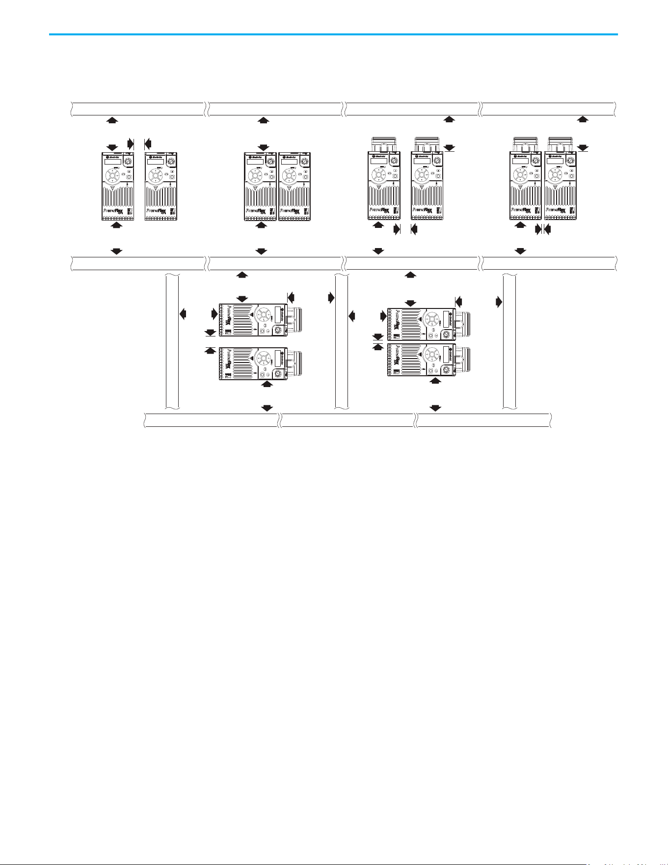
Minimum Mounting Clearances
See Product Dimensions on page 187 for mounting dimensions.
ATTENTION: The following information is merely a guide for proper
installation. Rockwell Automation cannot assume responsibility for the
compliance or the noncompliance to any code, national, local or otherwise
for the proper installation of this drive or associated equipment. A hazard of
personal injury and/or equipment damage exists if codes are ignored during
installation.
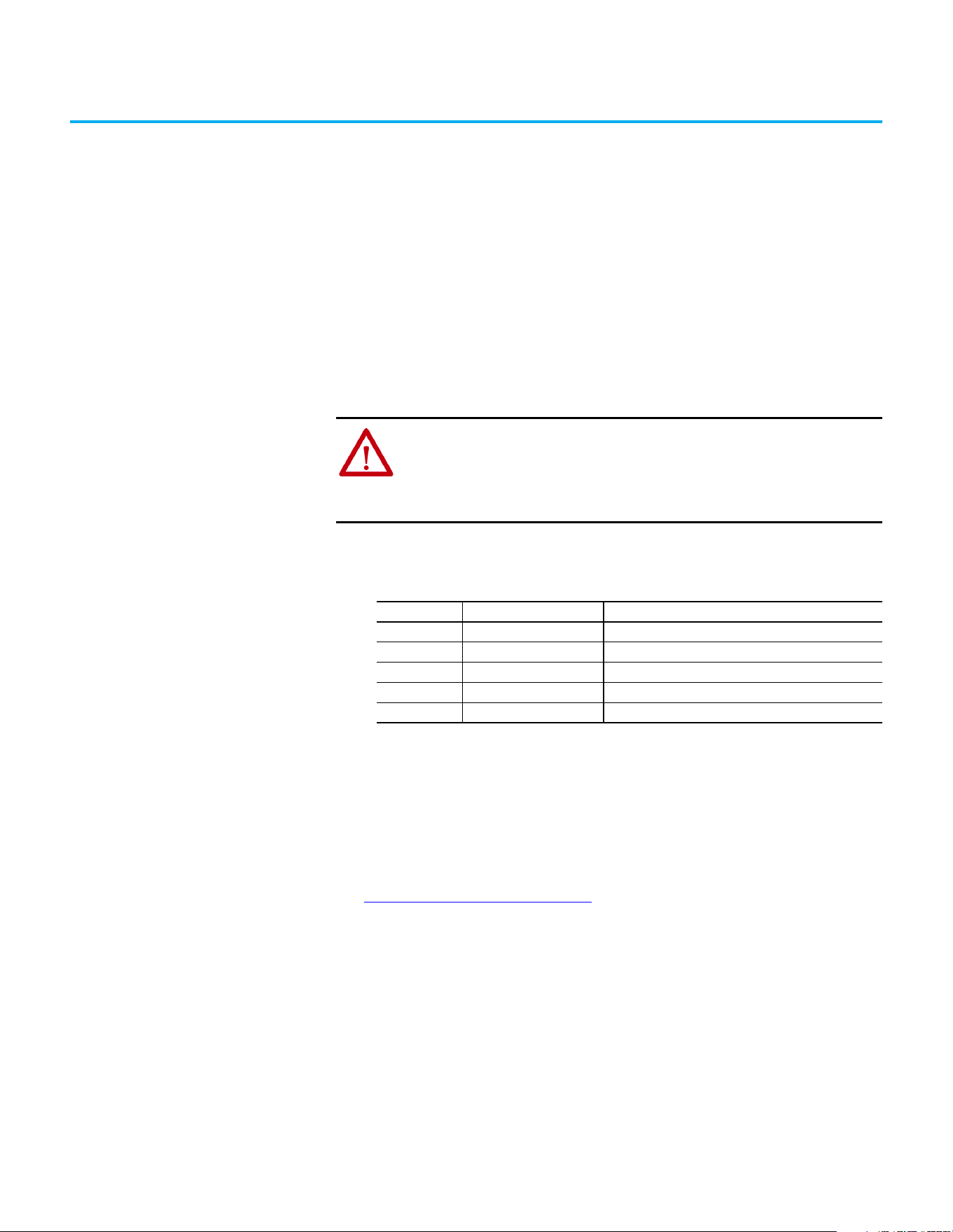
Frame Screw Size Screw Torque
A M5 (#10…24) 1.56…1.96 N•m (14…17 lb•in)
B M5 (#10…24) 1.56…1.96 N•m (14…17 lb•in)
C M5 (#10…24) 1.56…1.96 N•m (14…17 lb•in)
D M5 (#10…24) 2.45…2.94 N•m (22…26 lb•in)
E M8 (5/16 in) 6.0…7.4 N•m (53…65 lb•in)
Chapter 1 Installation/Wiring
16 Rockwell Automation Publication 520-UM001N-EN-E - July 2024
(1) For Frame E with Control Module Fan Kit only, clearance of 95 mm (3.7 in.) is required.
(2) For Frame E with Control Module Fan Kit only, clearance of 12 mm (0.5 in.) is required.
25 mm
(1.0 in.)
25 mm
(1.0 in.)
(2)
(2)
25 mm
(1.0 in.)
50 mm
(2.0 in.)
50 mm
(2.0 in.)
(1)
50 mm
(2.0 in.)
(1)
50 mm
(2.0 in.)
(1)
50 mm
(2.0 in.)
50 mm
(2.0 in.)
50 mm
(2.0 in.)
Esc
Sel
Esc
Sel
Esc
Sel
Esc
Sel
50 mm
(2.0 in.)
50 mm
(2.0 in.)
50 mm
(2.0 in.)
50 mm
(2.0 in.)
E
s
c
S
e
l
E
s
c
S
e
l
50 mm
(2.0 in.)
50 mm
(2.0 in.)
50 mm
(2.0 in.)
50 mm
(2.0 in.)
50 mm
(2.0 in.)
(1)
Esc
S
el
Esc
Se
l
Esc
Sel
Esc
Sel
Esc
Sel
Esc
Sel
Vertical, Zero Stacking
No clearance between drives.
Horizontal, Zero Stacking with
Control Module Fan Kit
No clearance between drives.
Vertical Vertical, Zero Stacking with
Control Module Fan Kit
No clearance between drives.
Vertical with Control Module Fan Kit
Horizontal with Control Module Fan Kit
Chapter 1 Installation/Wiring
Rockwell Automation Publication 520-UM001N-EN-E - July 2024 17
Ambient Operating Temperatures
For optional accessories and kits, see Accessories and Dimensions on page 175.
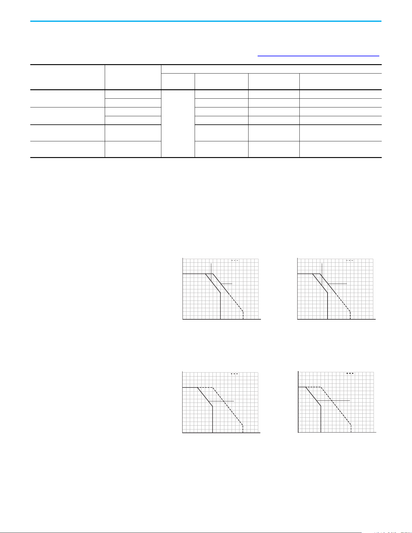
Current Derating Curves
Vertical Mounting
Horizontal/Floor Mounting
Mounting
Enclosure Rating
(1)
Ambient Temperature
Minimum Maximum (No Derate)
Maximum (Derate)
(2)
Maximum with
Control Module Fan Kit (Derate)
(3)(5)
Vertical
IP 20/Open Type
-20 °C (-4 °F)
50 °C (122 °F) 60 °C (140 °F) 70 °C (158 °F)
IP 30/NEMA 1/UL Type 1 45 °C (113 °F) 55 °C (131 °F) —
Vertical, Zero Stacking
IP 20/Open Type 45 °C (113 °F) 55 °C (131 °F) 65 °C (149 °F)
IP 30/NEMA 1/UL Type 1 40 °C (104 °F) 50 °C (122 °F) —
Horizontal with
Control Module Fan Kit
(4)(5)
IP 20/Open Type 50 °C (122 °F) — 70 °C (158 °F)
Horizontal, Zero Stacking
with Control Module Fan Kit
(4)(5)
IP 20/Open Type 45 °C (113 °F) — 65 °C (149 °F)
(1) IP 30/NEMA 1/UL Type 1 rating requires installation of the PowerFlex 520-series IP 30/NEMA 1/UL Type 1 option kit, 25-JBAx.
(2) For 25x-D1P4N104 and 25x-E0P9N104, the temperature that is listed under the Maximum (Derate) column is reduced by 5 °C (9 °F) for all mounting methods.
(3) For 25x-D1P4N104 and 25x-E0P9N104, the temperature that is listed under the Maximum with Control Module Fan Kit (Derate) column is reduced by 10 °C (18 °F) for vertical and vertical with
zero stacking mounting methods only.
(4) 25x-D1P4N104 and 25x-E0P9N104 cannot be mounted using either of the horizontal mounting methods.
(5) Requires installation of the PowerFlex 520-series Control Module Fan Kit, 25-FANx-70C.
Ambient Temperature (°C)
40
100
90
110
120
80
70
60
50
45403530
60 65 70 75 80
5550
Percentage of Rated Current (%)
IP 30/NEMA 1
with Control
Module Fan Kit
IP 20/Open Type
Ambient Temperature (°C)
40
100
90
110
120
80
70
60
50
45403530
60 65 70 75 80
5550
Percentage of Rated Current (%)
IP 30/NEMA 1
with Control
Module Fan Kit
IP 20/Open Type
Single Drive Zero Stacking
Ambient Temperature (°C)
40
100
90
120
110
80
70
60
50
30 35
70 75 80
60 6550 5540 45
Percentage of Rated Current (%)
with Control
Module Fan Kit
IP 20/Open Type
Ambient Temperature (°C)
40
100
90
120
110
80
70
60
50
30 35
70 75 80
60 6550 5540 45
Percentage of Rated Current (%)
with Control
Module Fan Kit
IP 20/Open Type
Single Drive Zero Stacking
Chapter 1 Installation/Wiring
18 Rockwell Automation Publication 520-UM001N-EN-E - July 2024
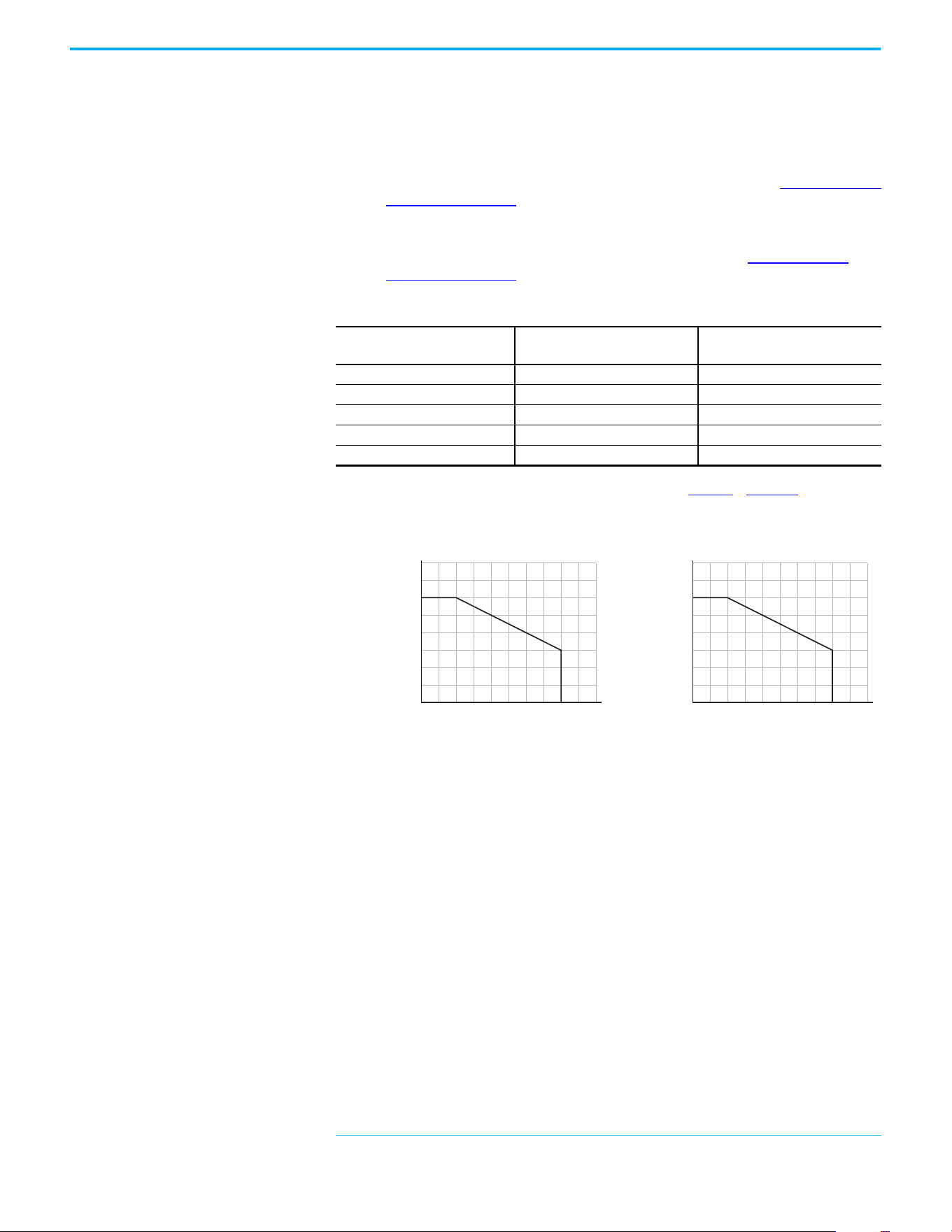
Derating Guidelines for High Altitude
The drive can be used without derating at a maximum altitude of
1000 m (3300 ft). If the drive is used above 1000 m (3300 ft):
• Derate the maximum ambient temper
ature by 5 °C (9 °F for every
ad
ditional 1000 m (3300 ft), subject to limits listed in the Altitude Limit
(Based on Voltage) table below.
Or
• Derate the output current by 10% for every additional 1000 m
(3300 ft),
up to 3000 m (9900 ft), subject to limits listed in the Al
titude Limit
(Based on Voltage) table below.
High Altitude
Debris Protection
Take precautions to prevent debris from falling through the vents of the drive
housing during installation.
Storage
• Store within an ambient temperature range of -40…+85 °C
(-40…+185 °F)
(a)
.
• Store within a relative humidity range of 0…95%, noncondensing.
• Do not expose to a corrosive atmosphere.
Altitude Limit (Based on Voltage)
Drive Rating
Center Ground (Wye Neutral)
(1)
(1) The circuit breaker that is used in the drive may have different altitude specifications. See the Motor Protection Circuit
Breaker and Motor Circuit Protector Specifications Technical Data, publication 140-TD005 or 140M-TD002.
Corner Ground, Impedance Ground,
or Ungrounded
(1)(2)
(2) Impedance Ground and Ungrounded limits are not evaluated as part of UL specifications.
100…120V 1-phase 6000 m (19,685 ft) 6000 m (19,685 ft)
200…240V 1-phase 2000 m (6562 ft) 2000 m (6562 ft)
200…240V 3-phase 6000 m (19,685 ft) 2000 m (6562 ft)
380…480V 3-phase 4000 m (13,123 ft) 2000 m (6562 ft)
525…600V 3-phase 2000 m (6562 ft) 2000 m (6562 ft)
(a) The maximum ambient temperature for storing a Frame E drive is 70 °C (158 °F).
Altitude (m)
Percentage of Rated Current (%)
40
90
100
110
120
80
70
60
50
0
4000
300020001000
Altitude (m)
Ambient Temperature (°C)
20
50
60
40
30
0
4000
300020001000
Chapter 1 Installation/Wiring
Rockwell Automation Publication 520-UM001N-EN-E - July 2024 19
AC Supply Source
Considerations
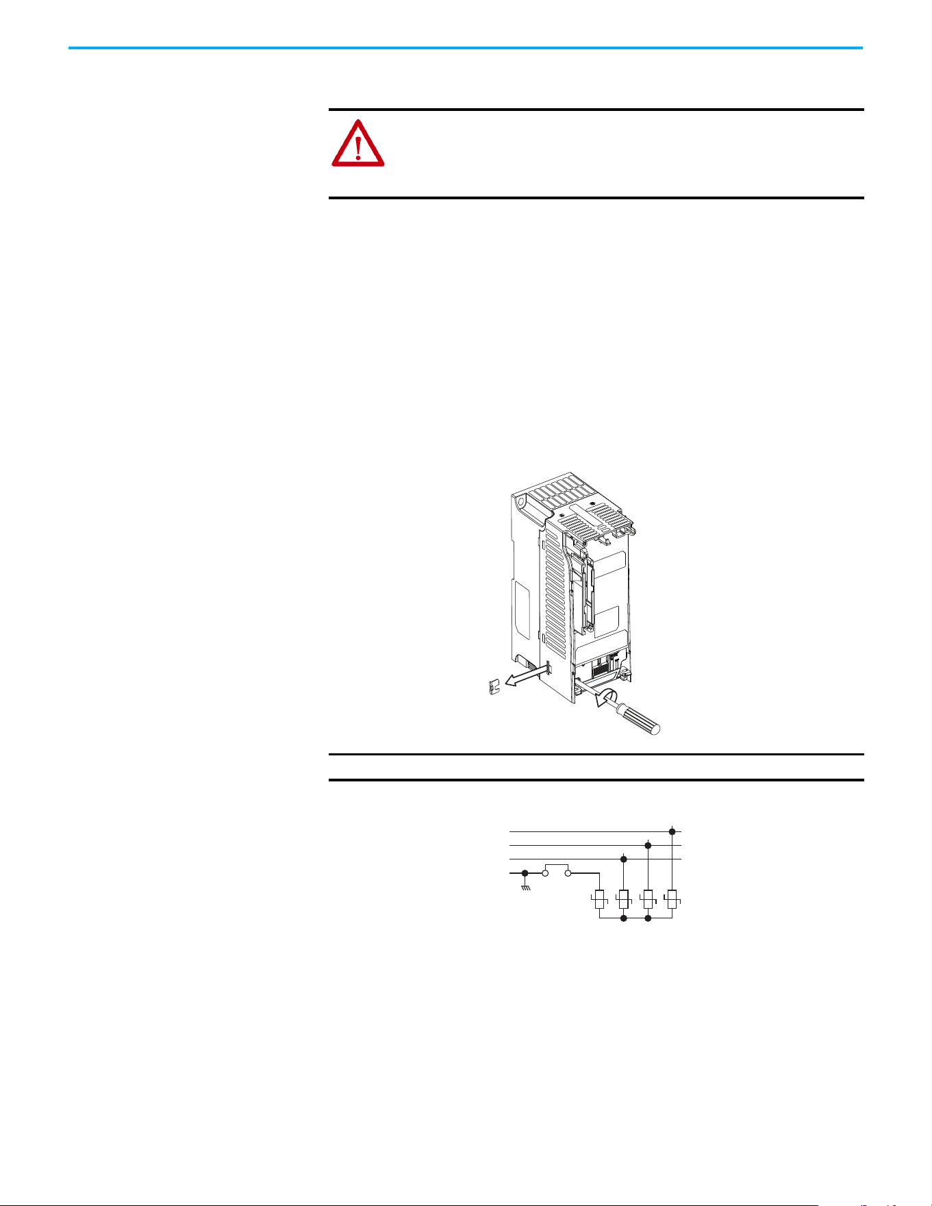
Ungrounded Distribution Systems
Disconnecting MOVs
To prevent drive damage, the MOVs connected to ground shall be
disconnected if the drive is installed on an ungrounded distribution system (IT
mains) where the line-to-ground voltages on any phase could exceed 125% of
the nominal line-to-line voltage. To disconnect these devices, remove the
jumper that is shown in the diagrams below.
1. Turn the screw counterclockwise to loosen.
2. Pull the jumper completely out of the drive chassis.
3. Tighten the screw to keep it in place.
Jumper Location (Typical)
Phase to Ground MOV Removal
ATTENTION: PowerFlex 520-series drives contain protective MOVs that are
referenced to ground. These devices must be disconnected if the drive is
installed on an ungrounded or resistive grounded distribution system.
ATTENTION: Removing MOVs in drives with an embedded filter will also
disconnect the filter capacitor from earth ground.
IMPORTANT Tighten screw after jumper removal.
Power Module
R/L1
S/L2
T/L3
1234
3-phase
AC input
Jumper
Chapter 1 Installation/Wiring
20 Rockwell Automation Publication 520-UM001N-EN-E - July 2024
Input Power Conditioning
The drive is suitable for direct connection to input power within the rated
voltage of the drive (see page 169
). Listed in the Input Power Conditions table
below are certain input power conditions, which may cause component
damage or reduction in product life. If any of these conditions exist, install one
of the devices that are listed under the heading Corrective Action on the line
side of the drive.
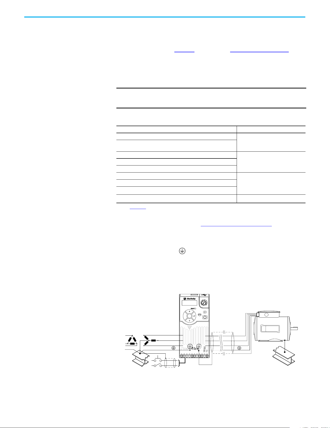
General Grounding
Requirements
The drive Safety Ground - (PE) must be connected to system ground.
Ground impedance must conform to the requirements of national and local
industrial safety regulations and/or electrical codes. The integrity of all ground
connections should be periodically checked.
Typical Grounding
IMPORTANT Only one device per branch circuit is required. It should be mounted
closest to the branch and sized to handle the total current of the branch
circuit.
Input Power Conditions
Input Power Condition Corrective Action
Low Line Impedance (less than 1% line reactance)
• Install Line Reactor.
(1)
or
• Install Isolation Transformer.
(1) See Appendix B for accessory ordering information.
Greater than 120 kVA supply transformer
Line has power factor correction capacitors
• Install Line Reactor.
(1)
or
• Install Isolation Transformer.
Line has frequent power interruptions
Line has intermittent noise spikes in excess of 6000V (lightning)
Phase to ground voltage exceeds 125% of normal line-to-line voltage • Remove MOV jumper to ground.
or
• Install Isolation Transformer with
grounded secondary if necessary.
Ungrounded distribution system
B-phase grounded distribution system
240V open delta configuration (stinger leg)
(2)
(2) For drives applied on an open delta with a middle phase grounded neutral system, the phase opposite the phase that is
tapped in the middle to the neutral or earth is referred to as the “stinger leg,” “high leg,” “red leg,” and so on. This leg should
be identified throughout the system with red or orange tape on the wire at each connection point. The stinger leg should be
connected to the center Phase B on the reactor. See Bulletin 1321-3R Series Line Reactors on page 185
for specific line
reactor part numbers.
• Install Line Reactor.
(1)
SHLD
U/T1
V/T2
W/T3
R/L1
S/L2
T/L3
Esc
Sel

Chapter 1 Installation/Wiring
Rockwell Automation Publication 520-UM001N-EN-E - July 2024 21
Ground Fault Monitoring
If a system ground fault monitor (RCD) is to be used, only Type B (adjustable)
devices should be used to avoid nuisance tripping.
Safety Ground - (PE)
This is the safety ground for the drive that is required by code. One of these
points must be connected to adjacent building steel (girder, joist), a floor
ground rod or busbar. Grounding points must comply with national and local
industrial safety regulations and/or electrical codes.
Network Ground
Connect terminal C1 to a clean earth ground when using a network with a star
topology (EtherNet/IP™) or daisy-chain (RS-485). It is acceptable to ground
both C1 and C2 terminals.
Note: Grounding C1 and C2 helps noise immunity for non-network
applications.
Connect terminal CS1 or CS2 to a clean ground when using a network with a
ring topology (EtherNet/IP).
For more information on EtherNet/IP networks, see Ground Connections for
EtherNet/IP Networks on page 250.
For more information on RS-485 networks, see Network Wiring on page 205
.
Motor Ground
The motor ground must be connected to one of the ground terminals on the
drive.
Shield Termination - SHLD
Either of the safety ground terminals that are on the power terminal block
provides a grounding point for the motor cable shield. The motor cable shield
connected to one of these terminals (drive end) should also be connected to the
motor frame (motor end). Use a shield terminating or EMI clamp to connect
the shield to the safety ground terminal. The earthing plate or conduit box
option may be used with a cable clamp for a grounding point for the cable
shield.
When shielded cable is used for control and signal wiring, the shield should be
grounded at the source end only, not at the drive end.

Chapter 1 Installation/Wiring
22 Rockwell Automation Publication 520-UM001N-EN-E - July 2024
RFI Filter Grounding
Using a drive with filter may result in relatively high ground leakage currents.
Therefore, the filter must only be used in installations with grounded AC
supply systems and be permanently installed and solidly grounded (bonded)
to the building power distribution ground. Ensure that the incoming supply
neutral is solidly connected (bonded) to the same building power distribution
ground. Grounding must not rely on flexible cables and should not include any
form of plug or socket that would permit inadvertent disconnection. Some
local codes may require redundant ground connections. The integrity of all
connections should be periodically checked.
Fuses and Circuit Breakers
The PowerFlex 520-series drive does not provide branch short circuit
protection. This product should be installed with either input fuses or an input
circuit breaker. National and local industrial safety regulations and/or
electrical codes may determine additional requirements for these installations.
The tables found on pages 23
...28 provide recommended AC line input fuse and
circuit breaker information. See Fusing and Circuit Breakers below for UL and
IEC requirements. Sizes that are listed are the recommended sizes based on
40 °C (104 °F) and the U.S. N.E.C. Other country, state, or local codes may
require different ratings.
Fusing
The recommended fuse types are listed in the tables that are found on pages
23
...28. If available current ratings do not match those listed in the tables that
are provided, choose the next higher fuse rating.
• IEC – BS88 (British Standard) Parts 1 & 2
(a)
, EN60269-1, Parts 1 & 2, type
GG or equivalent should be used.
• UL – UL Class CC, T, or J should be used.
Circuit Breakers
The “non-fuse” listings in the tables found on pages 23...28 include inverse time
circuit breakers, instantaneous trip circuit breakers (motor circuit protectors),
and 140M/140MT self-protected combination motor controllers. If one of these
is chosen as the desired protection method, the following requirements apply:
• IEC – Both types of circuit breakers and 140M/140MT self-protected
combination motor controllers are acceptable for IEC installations.
• UL – Only inverse time circuit breakers and the specified 140M/140MT
self-protected combination motor controllers are acceptable for UL
installations.
(a) Typical designations include, but may not be limited to the following;
Parts 1 & 2: AC, AD, BC, BD, CD, DD, ED, EFS, EF, FF, FG, GF, GG, GH.
Chapter 1 Installation/Wiring
Rockwell Automation Publication 520-UM001N-EN-E - July 2024 23
Bulletin 140M/140MT (Self-protected Combination Controller)/UL489 Circuit Breakers
When using Bulletin 140M/140MT or UL489 rated circuit breakers, the
guidelines that are listed below must be followed to meet the NEC
requirements for branch circuit protection.
• Bulletin 140M/140MT can be used in single motor applications.
• Bulletin 140M/140MT can be used up stream from the drive without the
need for fuses.
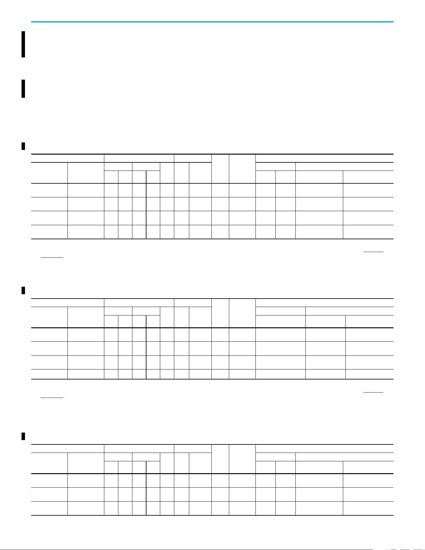
Fuses and Circuit Breakers for PowerFlex 520-series Drives
100…120V 1-phase Input Protection Devices – Frames A…B — IEC (Non-UL) Applications
Catalog No. Output Ratings Input Ratings
Frame
Size
Contactor
Cat. No.
IEC (Non-UL) Applications
PF 523 PF 525
ND HD
AkVA
Max
Current
A
(1)
Fuses (Rating) Circuit Breakers
Hp kW Hp kW Min Max 140U/140UT
140M/140MT
(2)(3)(4)
25A-V1P6N104 – 0.25 0.2 0.25 0.2 1.6 0.8 6.4 A
100-C09
100-E09
10 16
140U-D6D2-B80
140UT-D7D2-B80
140M-C2E-B63
140MT-C3E-B63
25A-V2P5N104 25B-V2P5N104 0.5 0.4 0.5 0.4 2.5 1.3 9.6 A
100-C12
100-E12
16 20
140U-D6D2-C12
140UT-D7D2-C12
140M-C2E-C10
140MT-C3E-C10
25A-V4P8N104 25B-V4P8N104 1.0 0.75 1.0 0.75 4.8 2.5 19.2 B
100-C23
100-E26
25 40
140U-D6D2-C25
140UT-D7D2-C25
140M-D8E-C20
140MT-D9E-C20
25A-V6P0N104 25B-V6P0N104 1.5 1.1 1.5 1.1 6.0 3.2 24.0 B 100-C23 32 50
140U-D6D2-C30
140UT-D7D2-C30
140M-F8E-C25
(1) When the drive is controlling motors with lower ampere ratings, see the drive nameplate for drive input current rating.
(2) The AIC ratings of the Bulletin 140M/140MT devices can vary. See the Motor Protection Circuit Breaker and Motor Circuit Protector Specifications Technical Data, publication 140-TD005
or
140M-TD002.
(3) Bulletin 140M/140MT devices with adjustable current range must have the current trip set to the minimum range that the device does not trip.
(4) Manual Self-protected (Type E) Combination Motor Controller, UL Listed for 208V Wye or Delta, 240V Wye or Delta, 480V Y/277 or 600V Y/347. Not UL Listed for use on 480V or 600V Delta/
Delta, corner ground, or high-resistance ground systems.
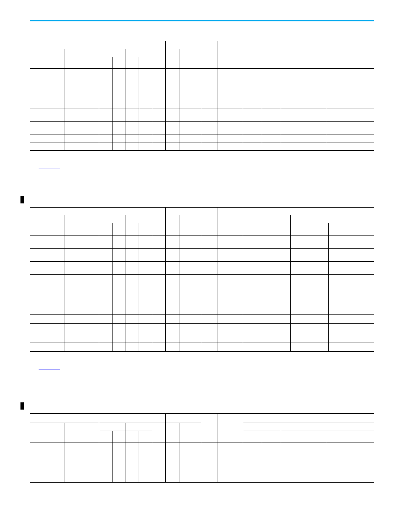
100…120V 1-phase Input Protection Devices – Frames A…B — UL 61800-5-1 Applications
Catalog Number Output Ratings Input Ratings
Frame
Size
Contactor
Catalog
Number
UL 61800-5-1 Applications
PF 523 PF 525
ND HD
AkVA
Max
Current
A
(1)
Fuses (Max Rating) Circuit Breakers
Hp kW Hp kW Class/Catalog Number. 140UT
140M/140MT
(2)(3)(4)
25A-V1P6N104 — 0.25 0.2 0.25 0.2 1.6 0.8 6.4 A
100-C09
100-E09
CLASS CC, J, or T/15 140UT-D7D2-B80
140MT-C3E-B63
140MT-D9E-B63
25A-V2P5N104 25B-V2P5N104 0.5 0.4 0.5 0.4 2.5 1.3 9.6 A
100-C12
100-E12
CLASS CC, J, or T/20 140UT-D7D2-C12
140MT-C3E-C10
140MT-D9E-C10
25A-V4P8N104 25B-V4P8N104 1.0 0.75 1.0 0.75 4.8 2.5 19.2 B
100-C23
100-E26
CLASS CC, J, or T/40
—
(5)
140MT-D9E-C20
25A-V6P0N104 25B-V6P0N104 1.5 1.1 1.5 1.1 6.0 3.2 24.0 B 100-C23 CLASS CC, J, or T/50
—
(5)
140M-F8E-C25
(1) When the drive is controlling motors with lower ampere ratings, see the drive nameplate for drive input current rating.
(2) The AIC ratings of the Bulletin 140M/140MT devices can vary. See the Motor Protection Circuit Breaker and Motor Circuit Protector Specifications Technical Data, publication 140-TD005 or
140M-TD002.
(3) Bulletin 140M/140MT devices with adjustable current range must have the current trip set to the minimum range that the device does not trip.
(4) Manual Self-protected (Type E) Combination Motor Controller, UL Listed for 208V Wye or Delta, 240V Wye or Delta, 480V Y/277 or 600V Y/347. Not UL Listed for use on 480V or 600V Delta/
Delta, corner ground, or high-resistance ground systems.
(5) Circuit breaker selection is not available for this drive rating.
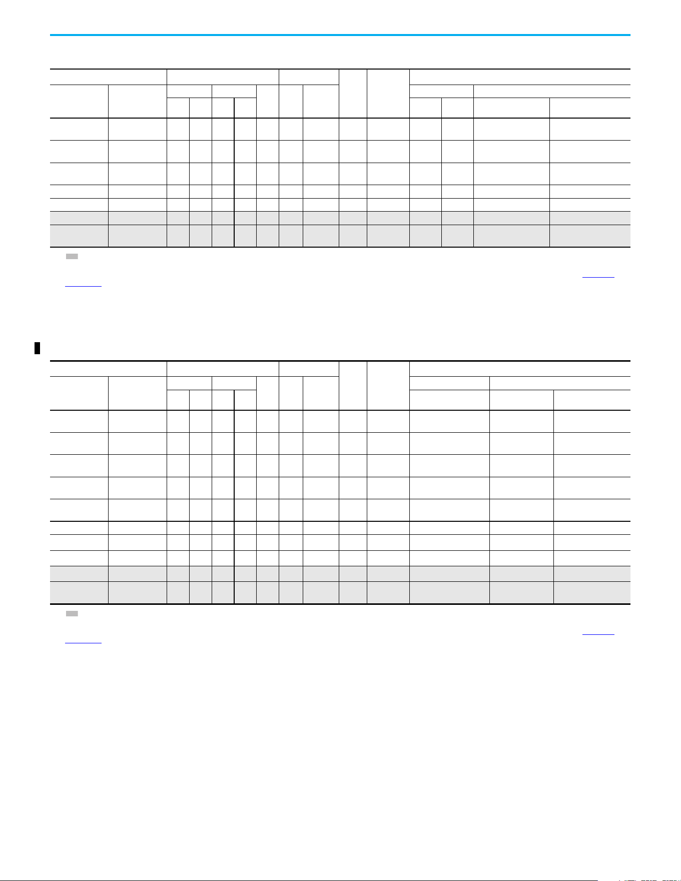
200…240V 1-phase Input Protection Devices – Frames A…B — IEC (Non-UL) Applications
Catalog Number Output Ratings Input Ratings
Frame
Size
Contactor
Catalog
Number
IEC (Non-UL) Applications
PF 523 PF 525
ND HD
AkVA
Max
Current
A
(1)
Fuses (Rating) Circuit Breakers
Hp kW Hp kW Min Max 140U/140UT/140G
140M/140MT
(2)(3)(4)
25A-A1P6N104 — 0.25 0.2 0.25 0.2 1.6 1.4 5.3 A
100-C09
100-E09
610
140U-D6D2-C10
140UT-D7D2-C10
140M-C2E-B63
140MT-C3E-B63
25A-A1P6N114 — 0.25 0.2 0.25 0.2 1.6 1.4 5.3 A
100-C09
100-E09
610
140U-D6D2-C10
140UT-D7D2-C10
140M-C2E-B63
140MT-C3E-B63
25A-A2P5N104 25B-A2P5N104 0.5 0.4 0.5 0.4 2.5 1.7 6.5 A
100-C09
100-E09
10 16
140U-D6D2-C10
140UT-D7D2-C10
140M-C2E-C10
140MT-C3E-C10
Chapter 1 Installation/Wiring
24 Rockwell Automation Publication 520-UM001N-EN-E - July 2024
25A-A2P5N114 25B-A2P5N114 0.5 0.4 0.5 0.4 2.5 1.7 6.5 A
100-C09
100-E09
10 16
140U-D6D2-C10
140UT-D7D2-C10
140M-C2E-C10
140MT-C3E-C10
25A-A4P8N104 25B-A4P8N104 1.0 0.75 1.0 0.75 4.8 2.8 10.7 A
100-C12
100-E12
16 25
140U-D6D2-C15
140UT-D7D2-C15
140M-C2E-C16
140MT-C3E-C16
25A-A4P8N114 25B-A4P8N114 1.0 0.75 1.0 0.75 4.8 2.8 10.7 A
100-C12
100-E12
16 25
140U-D6D2-C15
140UT-D7D2-C15
140M-C2E-C16
140MT-C3E-C16
25A-A8P0N104 25B-A8P0N104 2.0 1.5 2.0 1.5 8.0 4.8 18.0 B 100-C23 25 40
140U-D6D2-C25
140UT-D7D2-C25
140M-F8E-C25
25A-A8P0N114 25B-A8P0N114 2.0 1.5 2.0 1.5 8.0 4.8 18.0 B 100-C23 25 40
140U-D6D2-C25
140UT-D7D2-C25
140M-F8E-C25
25A-A011N104 25B-A011N104 3.0 2.2 3.0 2.2 11.0 6.0 22.9 B 100-C37 32 50 140G-G6C3-C35 140M-F8E-C25
25A-A011N114 25B-A011N114 3.0 2.2 3.0 2.2 11.0 6.0 22.9 B 100-C37 32 50 140G-G6C3-C35 140M-F8E-C25
(1) When the drive is controlling motors with lower ampere ratings, see the drive nameplate for drive input current rating.
(2) The AIC ratings of the Bulletin 140M/140MT devices can vary. See the Motor Protection Circuit Breaker and Motor Circuit Protector Specifications Technical Data, publication 140-TD005
or
140M-TD002
.
(3) Bulletin 140M/140MT devices with adjustable current range must have the current trip set to the minimum range that the device does not trip.
(4) Manual Self-protected (Type E) Combination Motor Controller, UL Listed for 208V Wye or Delta, 240V Wye or Delta, 480V Y/277 or 600V Y/347. Not UL Listed for use on 480V or 600V Delta/
Delta, corner ground, or high-resistance ground systems.
200…240V 1-phase Input Protection Devices – Frames A…B — IEC (Non-UL) Applications (Continued)
Catalog Number Output Ratings Input Ratings
Frame
Size
Contactor
Catalog
Number
IEC (Non-UL) Applications
PF 523 PF 525
ND HD
AkVA
Max
Current
A
(1)
Fuses (Rating) Circuit Breakers
Hp kW Hp kW Min Max 140U/140UT/140G
140M/140MT
(2)(3)(4)
200…240V 1-phase Input Protection Devices – Frames A…B — UL 61800-5-1 Applications
Catalog Number Output Ratings Input Ratings
Frame
Size
Contactor
Catalog
Number
UL 61800-5-1 Applications
PF 523 PF 525
ND HD
AkVA
Max
Current
A
(1)
Fuses (Max Rating) Circuit Breakers
Hp kW Hp kW Class/Catalog Number. 140UT
140M/140MT
(2)(3)(4)
25A-A1P6N104 — 0.25 0.2 0.25 0.2 1.6 1.4 5.3 A
100-C09
100-E09
CLASS CC, J, or T/15 140UT-D7D2-C10 140MT-D9E-B63
25A-A1P6N114 — 0.25 0.2 0.25 0.2 1.6 1.4 5.3 A
100-C09
100-E09
CLASS CC, J, or T/15 140UT-D7D2-C10 140MT-D9E-B63
25A-A2P5N104 25B-A2P5N104 0.5 0.4 0.5 0.4 2.5 1.7 6.5 A
100-C09
100-E09
CLASS CC, J, or T/15 140UT-D7D2-C10 140MT-D9E-C10
25A-A2P5N114 25B-A2P5N114 0.5 0.4 0.5 0.4 2.5 1.7 6.5 A
100-C09
100-E09
CLASS CC, J, or T/15 140UT-D7D2-C10 140MT-D9E-C10
25A-A4P8N104 25B-A4P8N104 1.0 0.75 1.0 0.75 4.8 2.8 10.7 A
100-C12
100-E12
CLASS CC, J, or T/25 140UT-D7D2-C15 140MT-D9E-C16
25A-A4P8N114 25B-A4P8N114 1.0 0.75 1.0 0.75 4.8 2.8 10.7 A
100-C12
100-E12
CLASS CC, J, or T/25 140UT-D7D2-C15 140MT-D9E-C16
25A-A8P0N104 25B-A8P0N104 2.0 1.5 2.0 1.5 8.0 4.8 18.0 B 100-C23 CLASS CC, J, or T/40
—
(5)
140M-F8E-C25
25A-A8P0N114 25B-A8P0N114 2.0 1.5 2.0 1.5 8.0 4.8 18.0 B 100-C23 CLASS CC, J, or T/40
—
(5)
140M-F8E-C25
25A-A011N104 25B-A011N104 3.0 2.2 3.0 2.2 11.0 6.0 22.9 B 100-C37 CLASS CC, J, or T/50
—
(5)
140M-F8E-C25
25A-A011N114 25B-A011N114 3.0 2.2 3.0 2.2 11.0 6.0 22.9 B 100-C37 CLASS CC, J, or T/50
—
(5)
140M-F8E-C25
(1) When the drive is controlling motors with lower ampere ratings, see the drive nameplate for drive input current rating.
(2) The AIC ratings of the Bulletin 140M/140MT devices can vary. See the Motor Protection Circuit Breaker and Motor Circuit Protector Specifications Technical Data, publication 140-TD005 or
140M-TD002
.
(3) Bulletin 140M/140MT devices with adjustable current range must have the current trip set to the minimum range that the device does not trip.
(4) Manual Self-protected (Type E) Combination Motor Controller, UL Listed for 208V Wye or Delta, 240V Wye or Delta, 480V Y/277 or 600V Y/347. Not UL Listed for use on 480V or 600V Delta/
Delta, corner ground, or high-resistance ground systems.
(5) Circuit breaker selection is not available for this drive rating.
200…240V 3-phase Input Protection Devices – Frames A…E — IEC (Non-UL) Applications
Catalog Number
(1)
Output Ratings Input Ratings
Frame
Size
Contactor
Catalog
Number
IEC (Non-UL) Applications
PF 523 PF 525
ND HD
AkVA
Max
Current
A
(2)
Fuses (Rating) Circuit Breakers
Hp kW Hp kW Min Max 140U/140UT/140G
140M/140MT
(3)(4)(5)
25A-B1P6N104 — 0.25 0.2 0.25 0.2 1.6 0.9 1.9 A
100-C09
100-E09
36
140U-D6D3-B30
140UT-D7D3-B30
140M-C2E-B25
140MT-C3E-B25
25A-B2P5N104 25B-B2P5N104 0.5 0.4 0.5 0.4 2.5 1.2 2.7 A
100-C09
100-E09
66
140U-D6D3-B40
140UT-D7D3-B40
140M-C2E-B40
140MT-C3E-B40
25A-B5P0N104 25B-B5P0N104 1.0 0.75 1.0 0.75 5.0 2.7 5.8 A
100-C09
100-E09
10 16
140U-D6D3-B80
140UT-D7D3-B80
140M-C2E-B63
140MT-C3E-B63
Chapter 1 Installation/Wiring
Rockwell Automation Publication 520-UM001N-EN-E - July 2024 25
25A-B8P0N104 25B-B8P0N104 2.0 1.5 2.0 1.5 8.0 4.3 9.5 A
100-C12
100-E12
16 20
140U-D6D3-C10
140UT-D7D3-C10
140M-C2E-C10
140MT-C3E-C10
25A-B011N104 25B-B011N104 3.0 2.2 3.0 2.2 11.0 6.3 13.8 A
100-C23
100-E26
20 32
140U-D6D3-C15
140UT-D7D3-C15
140M-C2E-C16
140MT-C3E-C16
25A-B017N104 25B-B017N104 5.0 4.0 5.0 4.0 17.5 9.6 21.1 B 100-C23 32 45
140U-D6D3-C25
140UT-D7D3-C25
140M-F8E-C25
25A-B024N104 25B-B024N104 7.5 5.5 7.5 5.5 24.0 12.2 26.6 C 100-C37 35 63 140G-G6C3-C35 140M-F8E-C32
25A-B032N104 25B-B032N104 10.0 7.5 10.0 7.5 32.2 15.9 34.8 D 100-C43 45 70 140G-G6C3-C60 140M-F8E-C45
25A-B048N104 25B-B048N104 15.0 11.0 10.0 7.5 48.3 20.1 44.0 E 100-C60 63 90 140G-G6C3-C70 140M-F8E-C45
25A-B062N104 25B-B062N104 20.0 15.0 15.0 11.0 62.1 25.6 56.0 E
100-C72
100-E65
70 125 140G-G6C3-C90
—
(6)
(1) Normal and Heavy-Duty ratings are available for this drive.
(2) When the drive is controlling motors with lower ampere ratings, see the drive nameplate for drive input current rating.
(3) The AIC ratings of the Bulletin 140M/140MT devices can vary. See the Motor Protection Circuit Breaker and Motor Circuit Protector Specifications Technical Data, publication 140-TD005
or
140M-TD002
.
(4) Bulletin 140M/140MT devices with adjustable current range must have the current trip set to the minimum range that the device does not trip.
(5) Manual Self-protected (Type E) Combination Motor Controller, UL Listed for 208V Wye or Delta, 240V Wye or Delta, 480V Y/277 or 600V Y/347. Not UL Listed for use on 480V or 600V Delta/
Delta, corner ground, or high-resistance ground systems.
(6) Circuit breaker selection is not available for this drive rating.
200…240V 3-phase Input Protection Devices – Frames A…E — IEC (Non-UL) Applications (Continued)
Catalog Number
(1)
Output Ratings Input Ratings
Frame
Size
Contactor
Catalog
Number
IEC (Non-UL) Applications
PF 523 PF 525
ND HD
AkVA
Max
Current
A
(2)
Fuses (Rating) Circuit Breakers
Hp kW Hp kW Min Max 140U/140UT/140G
140M/140MT
(3)(4)(5)
200…240V 3-phase Input Protection Devices – Frames A…E — UL 61800-5-1 Applications
Catalog Number
(1)
Output Ratings Input Ratings
Frame
Size
Contactor
Catalog
Number
UL 61800-5-1 Applications
PF 523 PF 525
ND HD
AkVA
Max
Current
A
(2)
Fuses (Max Rating) Circuit Breakers
Hp kW Hp kW Class/Catalog Number. 140UT
140M/140MT
(3)(4)(5)
25A-B1P6N104 — 0.25 0.2 0.25 0.2 1.6 0.9 1.9 A
100-C09
100-E09
CLASS CC, J, or T/6 140UT-D7D3-B30 140MT-D9E-B25
25A-B2P5N104 25B-B2P5N104 0.5 0.4 0.5 0.4 2.5 1.2 2.7 A
100-C09
100-E09
CLASS CC, J, or T/6 140UT-D7D3-B40 140MT-D9E-B40
25A-B5P0N104 25B-B5P0N104 1.0 0.75 1.0 0.75 5.0 2.7 5.8 A
100-C09
100-E09
CLASS CC, J, or T/15 140UT-D7D3-B80 140MT-D9E-B63
25A-B8P0N104 25B-B8P0N104 2.0 1.5 2.0 1.5 8.0 4.3 9.5 A
100-C12
100-E12
CLASS CC, J, or T/20 140UT-D7D3-C10 140MT-D9E-C10
25A-B011N104 25B-B011N104 3.0 2.2 3.0 2.2 11.0 6.3 13.8 A
100-C23
100-E26
CLASS CC, J, or T/30 140UT-D7D3-C15 140MT-D9E-C16
25A-B017N104 25B-B017N104 5.0 4.0 5.0 4.0 17.5 9.6 21.1 B 100-C23 CLASS CC, J, or T/45 140UT-D7D3-C25 140M-F8E-C25
25A-B024N104 25B-B024N104 7.5 5.5 7.5 5.5 24.0 12.2 26.6 C 100-C37 CLASS CC, J, or T/60
—
(6)
140M-F8E-C32
25A-B032N104 25B-B032N104 10.0 7.5 10.0 7.5 32.2 15.9 34.8 D 100-C43 CLASS CC, J, or T/70
—
(6)
140M-F8E-C45
25A-B048N104 25B-B048N104 15.0 11.0 10.0 7.5 48.3 20.1 44.0 E 100-C60 CLASS CC, J, or T/90
—
(6)
140M-F8E-C45
25A-B062N104 25B-B062N104 20.0 15.0 15.0 11.0 62.1 25.6 56.0 E
100-C72
100-E65
CLASS CC, J, or T/125
—
(6)
—
(6)
(1) Normal and Heavy-Duty ratings are available for this drive.
(2) When the drive is controlling motors with lower ampere ratings, see the drive nameplate for drive input current rating.
(3) The AIC ratings of the Bulletin 140M/140MT devices can vary. See the Motor Protection Circuit Breaker and Motor Circuit Protector Specifications Technical Data, publication 140-TD005
or
140M-TD002
.
(4) Bulletin 140M/140MT devices with adjustable current range must have the current trip set to the minimum range that the device does not trip.
(5) Manual Self-protected (Type E) Combination Motor Controller, UL Listed for 208V Wye or Delta, 240V Wye or Delta, 480V Y/277 or 600V Y/347. Not UL Listed for use on 480V or 600V Delta/
Delta, corner ground, or high-resistance ground systems.
(6) Circuit breaker selection is not available for this drive rating.
Chapter 1 Installation/Wiring
26 Rockwell Automation Publication 520-UM001N-EN-E - July 2024
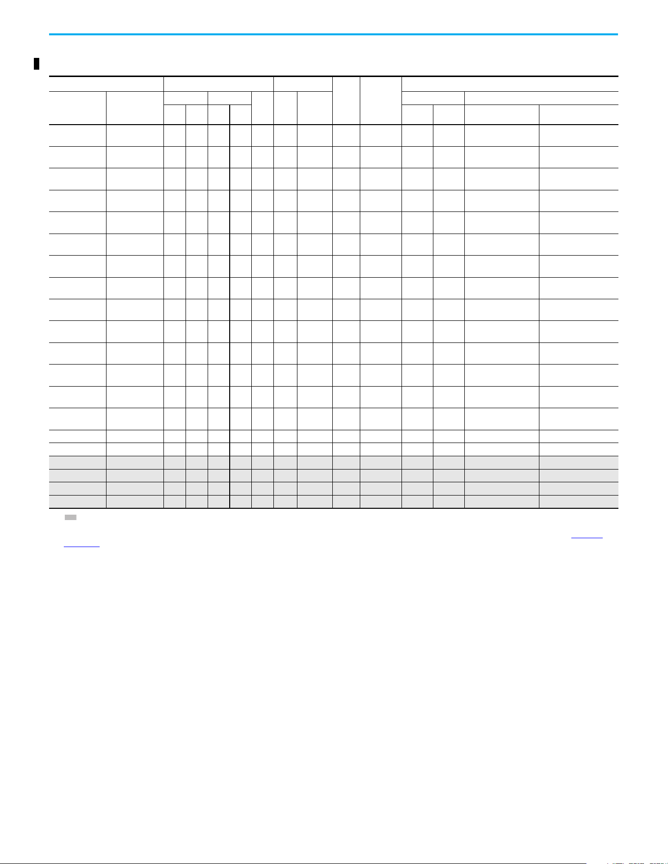
380…480V 3-phase Input Protection Devices – Frames A…E — IEC (Non-UL) Applications
Catalog Number
(1)
Output Ratings Input Ratings
Frame
Size
Contactor
Catalog
Number
IEC (Non-UL) Applications
PF 523 PF 525
ND HD
AkVA
Max
Current
A
(2)
Fuses (Rating) Circuit Breakers
Hp kW Hp kW Min Max 140U/140UT/140G
140M/140MT
(3)(4)(5)
25A-D1P4N104 25B-D1P4N104 0.5 0.4 0.5 0.4 1.4 1.7 1.9 A
100-C09
100-E09
36
140U-D6D3-B30
140UT-D7D3-B30
140M-C2E-B25
140MT-C3E-B25
25A-D1P4N114 25B-D1P4N114 0.5 0.4 0.5 0.4 1.4 1.7 1.9 A
100-C09
100-E09
36
140U-D6D3-B30
140UT-D7D3-B30
140M-C2E-B25
140MT-C3E-B25
25A-D2P3N104 25B-D2P3N104 1.0 0.75 1.0 0.75 2.3 2.9 3.2 A
100-C09
100-E09
610
140U-D6D3-B60
140UT-D7D3-B60
140M-C2E-B40
140MT-C3E-B40
25A-D2P3N114 25B-D2P3N114 1.0 0.75 1.0 0.75 2.3 2.9 3.2 A
100-C09
100-E09
610
140U-D6D3-B60
140UT-D7D3-B60
140M-C2E-B40
140MT-C3E-B40
25A-D4P0N104 25B-D4P0N104 2.0 1.5 2.0 1.5 4.0 5.2 5.7 A
100-C09
100-E09
10 16
140U-D6D3-B60
140UT-D7D3-B60
140M-C2E-B63
140MT-C3E-B63
25A-D4P0N114 25B-D4P0N114 2.0 1.5 2.0 1.5 4.0 5.2 5.7 A
100-C09
100-E09
10 16
140U-D6D3-B60
140UT-D7D3-B60
140M-C2E-B63
140MT-C3E-B63
25A-D6P0N104 25B-D6P0N104 3.0 2.2 3.0 2.2 6.0 6.9 7.5 A
100-C09
100-E09
10 16
140U-D6D3-C10
140UT-D7D3-C10
140M-C2E-C10
140MT-C3E-C10
25A-D6P0N114 25B-D6P0N114 3.0 2.2 3.0 2.2 6.0 6.9 7.5 A
100-C09
100-E09
10 16
140U-D6D3-C10
140UT-D7D3-C10
140M-C2E-C10
140MT-C3E-C10
25A-D010N104 25B-D010N104 5.0 4.0 5.0 4.0 10.5 12.6 13.8 B
100-C23
100-E26
20 32
140U-D6D3-C15
140UT-D7D3-C15
140M-C2E-C16
140MT-C3E-C16
25A-D010N114 25B-D010N114 5.0 4.0 5.0 4.0 10.5 12.6 13.8 B
100-C23
100-E26
20 32
140U-D6D3-C15
140UT-D7D3-C15
140M-C2E-C16
140MT-C3E-C16
25A-D013N104 25B-D013N104 7.55.57.55.513.014.1 15.4 C
100-C23
100-E26
20 35
140U-D6D3-C25
140UT-D7D3-C25
140M-D8E-C20
140MT-D9E-C20
25A-D013N114 25B-D013N114 7.5 5.5 7.5 5.5 13.0 14.1 15.4 C
100-C23
100-E26
20 35
140U-D6D3-C25
140UT-D7D3-C25
140M-D8E-C20
140MT-D9E-C20
25A-D017N104 25B-D017N104 10.0 7.5 10.0 7.5 17.0 16.8 18.4 C
100-C23
100-E26
25 40
140U-D6D3-C25
140UT-D7D3-C25
140M-D8E-C20
140MT-D9E-C20
25A-D017N114 25B-D017N114 10.0 7.5 10.0 7.5 17.0 16.8 18.4 C
100-C23
100-E26
25 40
140U-D6D3-C25
140UT-D7D3-C25
140M-D8E-C20
140MT-D9E-C20
25A-D024N104 25B-D024N104 15.0 11.0 15.0 11.0 24.0 24.1 26.4 D 100-C37 35 63 140G-G6C3-C40 140M-F8E-C32
25A-D024N114 25B-D024N114 15.0 11.0 15.0 11.0 24.0 24.1 26.4 D 100-C37 35 63 140G-G6C3-C40 140M-F8E-C32
25A-D030N104 25B-D030N104 20.0 15.0 15.0 11.0 30.0 30.2 33.0 D 100-C43 45 70 140G-G6C3-C50 140M-F8E-C45
25A-D030N114 25B-D030N114 20.0 15.0 15.0 11.0 30.0 30.2 33.0 D 100-C43 45 70 140G-G6C3-C50 140M-F8E-C45
25A-D037N114 25B-D037N114 25.0 18.5 20.0 15.0 37.0 30.8 33.7 E 100-C43 45 70 140G-G6C3-C50 140M-F8E-C45
25A-D043N114 25B-D043N114 30.0 22.0 25.0 18.5 43.0 35.6 38.9 E 100-C60 50 80 140G-G6C3-C60 140M-F8E-C45
(1) Normal and Heavy-Duty ratings are available for this drive.
(2) When the drive is controlling motors with lower ampere ratings, see the drive nameplate for drive input current rating.
(3) The AIC ratings of the Bulletin 140M/140MT devices can vary. See the Motor Protection Circuit Breaker and Motor Circuit Protector Specifications Technical Data, publication 140-TD005
or
140M-TD002
.
(4) Bulletin 140M/140MT devices with adjustable current range must have the current trip set to the minimum range that the device does not trip.
(5) Manual Self-protected (Type E) Combination Motor Controller, UL Listed for 208V Wye or Delta, 240V Wye or Delta, 480V Y/277 or 600V Y/347. Not UL Listed for use on 480V or 600V Delta/
Delta, corner ground, or high-resistance ground systems.
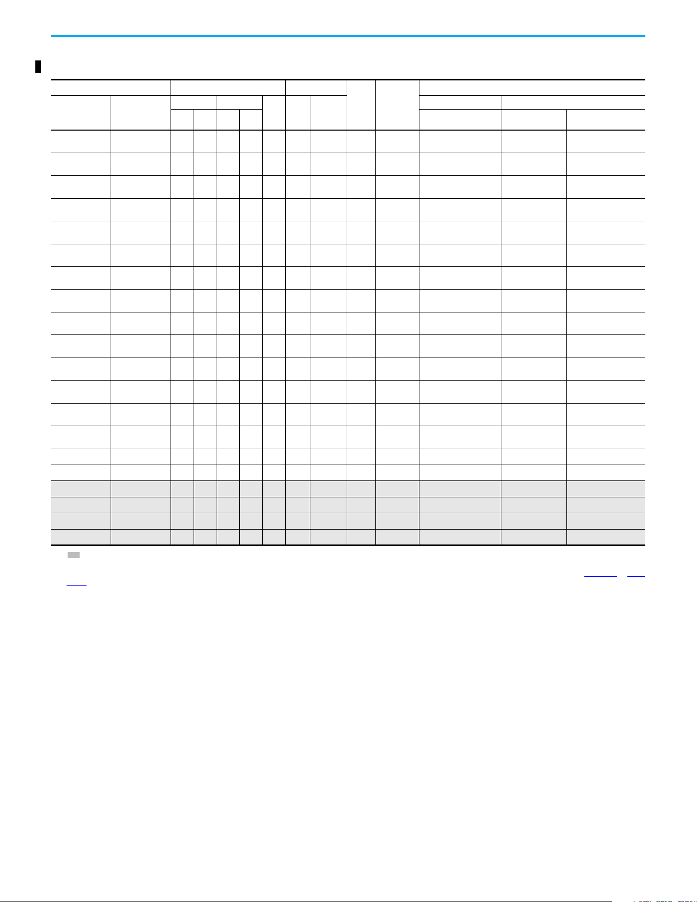
Chapter 1 Installation/Wiring
Rockwell Automation Publication 520-UM001N-EN-E - July 2024 27
380…480V 3-phase Input Protection Devices – Frames A…E — UL 61800-5-1 Applications
Catalog Number
(1)
Output Ratings Input Ratings
Frame
Size
Contactor
Catalog
Number
UL 61800-5-1 Applications
PF 523 PF 525
ND HD
AkVA
Max
Current
A
(2)
Fuses (Max Rating) Circuit Breakers
Hp kW Hp kW Class/Catalog Number. 140UT
140M/140MT
(3)(4)(5)
25A-D1P4N104 25B-D1P4N104 0.5 0.4 0.5 0.4 1.4 1.7 1.9 A
100-C09
100-E09
CLASS CC, J, or T/6
—
(6)
140MT-C3E-B25
25A-D1P4N114 25B-D1P4N114 0.5 0.4 0.5 0.4 1.4 1.7 1.9 A
100-C09
100-E09
CLASS CC, J, or T/6
—
(6)
140MT-C3E-B25
25A-D2P3N104 25B-D2P3N104 1.0 0.75 1.0 0.75 2.3 2.9 3.2 A
100-C09
100-E09
CLASS CC, J, or T/10
—
(6)
140MT-C3E-B40
25A-D2P3N114 25B-D2P3N114 1.0 0.75 1.0 0.75 2.3 2.9 3.2 A
100-C09
100-E09
CLASS CC, J, or T/10
—
(6)
140MT-C3E-B40
25A-D4P0N104 25B-D4P0N104 2.0 1.5 2.0 1.5 4.0 5.2 5.7 A
100-C09
100-E09
CLASS CC, J, or T/15
—
(6)
140MT-C3E-B63
25A-D4P0N114 25B-D4P0N114 2.0 1.5 2.0 1.5 4.0 5.2 5.7 A
100-C09
100-E09
CLASS CC, J, or T/15
—
(6)
140MT-C3E-B63
25A-D6P0N104 25B-D6P0N104 3.0 2.2 3.0 2.2 6.0 6.9 7.5 A
100-C09
100-E09
CLASS CC, J, or T/15
—
(6)
140MT-C3E-C10
25A-D6P0N114 25B-D6P0N114 3.0 2.2 3.0 2.2 6.0 6.9 7.5 A
100-C09
100-E09
CLASS CC, J, or T/15
—
(6)
140MT-C3E-C10
25A-D010N104 25B-D010N104 5.0 4.0 5.0 4.0 10.5 12.6 13.8 B
100-C23
100-E26
CLASS CC, J, or T/30
—
(6)
140MT-D9E-C16
25A-D010N114 25B-D010N114 5.0 4.0 5.0 4.0 10.5 12.6 13.8 B
100-C23
100-E26
CLASS CC, J, or T/30
—
(6)
140MT-D9E-C16
25A-D013N104 25B-D013N104 7.55.57.55.513.014.1 15.4 C
100-C23
100-E26
CLASS CC, J, or T/35
—
(6)
140MT-D9E-C20
25A-D013N114 25B-D013N114 7.5 5.5 7.5 5.5 13.0 14.1 15.4 C
100-C23
100-E26
CLASS CC, J, or T/35
—
(6)
140MT-D9E-C20
25A-D017N104 25B-D017N104 10.0 7.5 10.0 7.5 17.0 16.8 18.4 C
100-C23
100-E26
CLASS CC, J, or T/40
—
(6)
140MT-D9E-C20
25A-D017N114 25B-D017N114 10.0 7.5 10.0 7.5 17.0 16.8 18.4 C
100-C23
100-E26
CLASS CC, J, or T/40
—
(6)
140MT-D9E-C20
25A-D024N104 25B-D024N104 15.0 11.0 15.0 11.0 24.0 24.1 26.4 D 100-C37 CLASS CC, J, or T/60
—
(6)
140M-F8E-C32
25A-D024N114 25B-D024N114 15.0 11.0 15.0 11.0 24.0 24.1 26.4 D 100-C37 CLASS CC, J, or T/60
—
(6)
140M-F8E-C32
25A-D030N104 25B-D030N104 20.0 15.0 15.0 11.0 30.0 30.2 33.0 D 100-C43 CLASS CC, J, or T/70
—
(6)
140M-F8E-C45
25A-D030N114 25B-D030N114 20.0 15.0 15.0 11.0 30.0 30.2 33.0 D 100-C43 CLASS CC, J, or T/70
—
(6)
140M-F8E-C45
25A-D037N114 25B-D037N114 25.0 18.5 20.0 15.0 37.0 30.8 33.7 E 100-C43 CLASS CC, J, or T/70
—
(6)
140M-F8E-C45
25A-D043N114 25B-D043N114 30.0 22.0 25.0 18.5 43.0 35.6 38.9 E 100-C60 CLASS CC, J, or T/80
—
(6)
140M-F8E-C45
(1) Normal and Heavy-Duty ratings are available for this drive.
(2) When the drive is controlling motors with lower ampere ratings, see the drive nameplate for drive input current rating.
(3) The AIC ratings of the Bulletin 140M/MT devices can vary. See the Motor Protection Circuit Breaker and Motor Circuit Protector Specifications Technical Data, publication140-TD005
or 140M-
TD002.
(4) Bulletin 140M/MT devices with adjustable current range must have the current trip set to the minimum range that the device does not trip.
(5) Manual Self-protected (Type E) Combination Motor Controller, UL Listed for 208V Wye or Delta, 240V Wye or Delta, 480V Y/277 or 600V Y/347. Not UL Listed for use on 480V or 600V Delta/
Delta, corner ground, or high-resistance ground systems.
(6) Circuit breaker selection is not available for this drive rating.
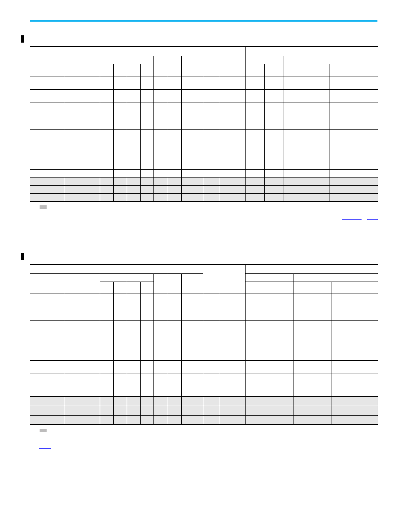
Chapter 1 Installation/Wiring
28 Rockwell Automation Publication 520-UM001N-EN-E - July 2024
525…600V 3-phase Input Protection Devices – Frames A…E — IEC (Non-UL) Applications
Catalog Number
(1)
Output Ratings Input Ratings
Frame
Size
Contactor
Catalog
Number
IEC (Non-UL) Applications
PF 523 PF 525
ND HD
AkVA
Max
Current
A
(2)
Fuses (Rating) Circuit Breakers
Hp kW Hp kW Min Max 140U/140UT/140G
140M/140MT
(3)(4)(5)
25A-E0P9N104 25B-E0P9N104 0.5 0.4 0.5 0.4 0.9 1.4 1.2 A
100-C09
100-E09
36
140U-D6D3-B20
140UT-D7D3-B20
140M-C2E-B25
140MT-C3E-B25
25A-E1P7N104 25B-E1P7N104 1.0 0.75 1.0 0.75 1.7 2.6 2.3 A
100-C09
100-E09
36
140U-D6D3-B30
140UT-D7D3-B30
140M-C2E-B25
140MT-C3E-B25
25A-E3P0N104 25B-E3P0N104 2.0 1.5 2.0 1.5 3.0 4.3 3.8 A
100-C09
100-E09
610
140U-D6D3-B50
140UT-D7D3-B50
140M-C2E-B40
140MT-C3E-B40
25A-E4P2N104 25B-E4P2N104 3.0 2.2 3.0 2.2 4.2 6.1 5.3 A
100-C09
100-E09
10 16
140U-D6D3-B80
140UT-D7D3-B80
140M-C2E-B63
140MT-D9E-B63
25A-E6P6N104 25B-E6P6N104 5.0 4.0 5.0 4.0 6.6 9.1 8.0 B
100-C09
100-E09
10 20
140U-D6D3-C10
140UT-D7D3-C10
140M-C2E-C10
140MT-D9E-C10
25A-E9P9N104 25B-E9P9N104 7.5 5.5 7.5 5.5 9.9 12.8 11.2 C
100-C16
100-E16
16 25
140U-D6D3-C15
140UT-D7D3-C15
140M-C2E-C16
140MT-D9E-C16
25A-E012N104 25B-E012N104 10.0 7.5 10.0 7.5 12.0 15.4 13.5 C
100-C23
100-E26
20 32 140U-D6D3-C20
140M-C2E-C16
140MT-D9E-C16
25A-E019N104 25B-E019N104 15.0 11.0 15.0 11.0 19.0 27.4 24.0 D 100-C30 32 50 140G-G6C3-C30 140M-F8E-C25
25A-E022N104 25B-E022N104 20.0 15.0 15.0 11.0 22.0 31.2 27.3 D 100-C30 35 63 140G-G6C3-C35 140M-F8E-C32
25A-E027N104 25B-E027N104 25.0 18.5 20.0 15.0 27.0 28.2 24.7 E 100-C30 35 50 140G-G6C3-C35 140M-F8E-C32
25A-E032N104 25B-E032N104 30.0 22.0 25.0 18.5 32.0 33.4 29.2 E 100-C37 40 63 140G-G6C3-C50 140M-F8E-C32
(1) Normal and Heavy-Duty ratings are available for this drive.
(2) When the drive is controlling motors with lower ampere ratings, see the drive nameplate for drive input current rating.
(3) The AIC ratings of the Bulletin 140M/MT devices can vary. See the Motor Protection Circuit Breaker and Motor Circuit Protector Specifications Technical Data, publication 140-TD005
or 140M-
TD002.
(4) Bulletin 140M/MT devices with adjustable current range must have the current trip set to the minimum range that the device does not trip.
(5) Manual Self-protected (Type E) Combination Motor Controller, UL Listed for 208V Wye or Delta, 240V Wye or Delta, 480V Y/277 or 600V Y/347. Not UL Listed for use on 480V or 600V Delta/
Delta, corner ground, or high-resistance ground systems.
525…600V 3-phase Input Protection Devices – Frames A…E — UL 61800-5-1 Applications
Catalog Number
(1)
Output Ratings Input Ratings
Frame
Size
Contactor
Catalog
Number
UL 61800-5-1 Applications
PF 523 PF 525
ND HD
AkVA
Max
Current
A
(2)
Fuses (Max Rating) Circuit Breakers
Hp kW Hp kW Class/Catalog Number. 140UT
140M/140MT
(3)(4)(5)
25A-E0P9N104 25B-E0P9N104 0.5 0.4 0.5 0.4 0.9 1.4 1.2 A
100-C09
100-E09
CLASS CC, J, or T/6
—
(6)
140MT-C3E-B25
25A-E1P7N104 25B-E1P7N104 1.0 0.75 1.0 0.75 1.7 2.6 2.3 A
100-C09
100-E09
CLASS CC, J, or T/6
—
(6)
140MT-C3E-B25
25A-E3P0N104 25B-E3P0N104 2.0 1.5 2.0 1.5 3.0 4.3 3.8 A
100-C09
100-E09
CLASS CC, J, or T/10
—
(6)
140MT-C3E-B40
25A-E4P2N104 25B-E4P2N104 3.0 2.2 3.0 2.2 4.2 6.1 5.3 A
100-C09
100-E09
CLASS CC, J, or T/15
—
(6)
140MT-D9E-B63
25A-E6P6N104 25B-E6P6N104 5.0 4.0 5.0 4.0 6.6 9.1 8.0 B
100-C09
100-E09
CLASS CC, J, or T/20
—
(6)
140MT-D9E-C10
25A-E9P9N104 25B-E9P9N104 7.5 5.5 7.5 5.5 9.9 12.8 11.2 C
100-C16
100-E16
CLASS CC, J, or T/25
—
(6)
140MT-D9E-C16
25A-E012N104 25B-E012N104 10.0 7.5 10.0 7.5 12.0 15.4 13.5 C
100-C23
100-E26
CLASS CC, J, or T/30
—
(6)
140MT-D9E-C16
25A-E019N104 25B-E019N104 15.0 11.0 15.0 11.0 19.0 27.4 24.0 D 100-C30 CLASS CC, J, or T/50
—
(6)
140M-F8E-C25
25A-E022N104 25B-E022N104 20.0 15.0 15.0 11.0 22.0 31.2 27.3 D 100-C30 CLASS CC, J, or T/60
—
(6)
140M-F8E-C32
25A-E027N104 25B-E027N104 25.0 18.5 20.0 15.0 27.0 28.2 24.7 E 100-C30 CLASS CC, J, or T/50
—
(6)
140M-F8E-C32
25A-E032N104 25B-E032N104 30.0 22.0 25.0 18.5 32.0 33.4 29.2 E 100-C37 CLASS CC, J, or T/60
—
(6)
140M-F8E-C32
(1) Normal and Heavy-Duty ratings are available for this drive.
(2) When the drive is controlling motors with lower ampere ratings, see the drive nameplate for drive input current rating.
(3) The AIC ratings of the Bulletin 140M/MT devices can vary. See the Motor Protection Circuit Breaker and Motor Circuit Protector Specifications Technical Data, publication 140-TD005
or 140M-
TD002.
(4) Bulletin 140M/MT devices with adjustable current range must have the current trip set to the minimum range that the device does not trip.
(5) Manual Self-protected (Type E) Combination Motor Controller, UL Listed for 208V Wye or Delta, 240V Wye or Delta, 480V Y/277 or 600V Y/347. Not UL Listed for use on 480V or 600V Delta/
Delta, corner ground, or high-resistance ground systems.
(6) Circuit breaker selection is not available for this drive rating.
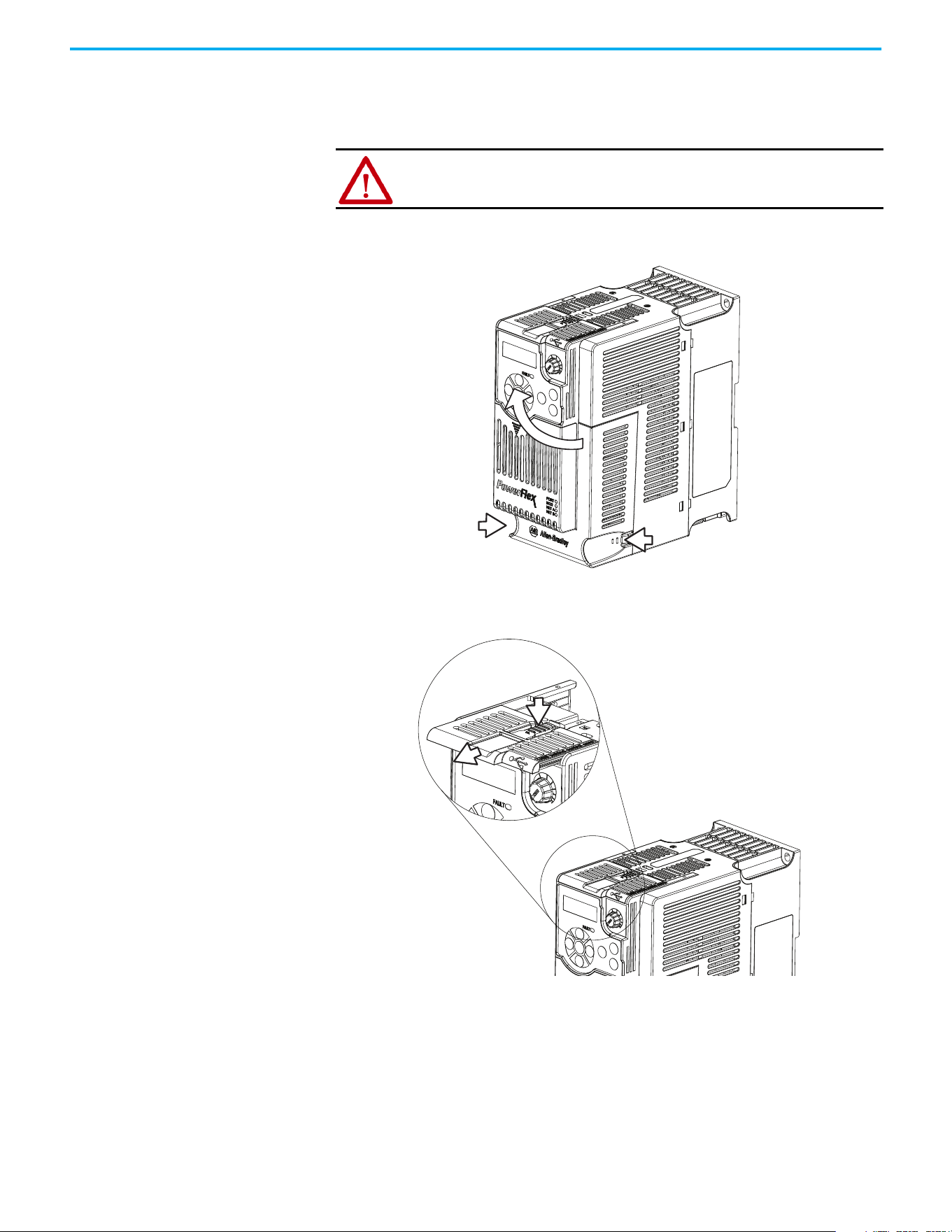
Chapter 1 Installation/Wiring
Rockwell Automation Publication 520-UM001N-EN-E - July 2024 29
Power and Control Module
PowerFlex 520-series drives consist of a Power Module and Control Module.
Separating the Power and Control Module
1. Press and hold down the catch on both sides of the frame cover, then
pull out and swing upwards to remove (Frames B…E only).
2. Press down and slide out the top cover of the Control Module to unlock
it from the Power Module.
ATTENTION: Perform this action only when drive is NOT powered.
1
2
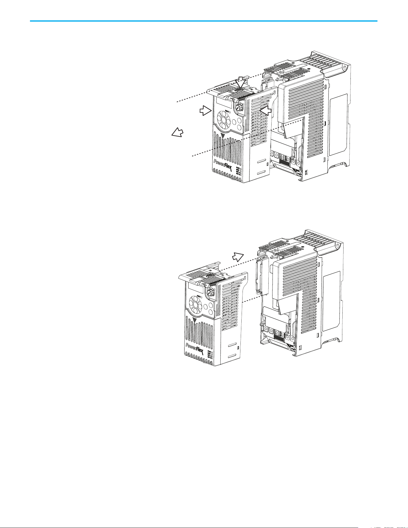
Chapter 1 Installation/Wiring
30 Rockwell Automation Publication 520-UM001N-EN-E - July 2024
3. Hold the sides and top of the Control Module firmly, then pull out to
separate it from the Power Module.
Connecting the Power and Control Module
1. Align the connectors on the Power Module and Control Module, then
push the Control Module firmly onto the Power Module.
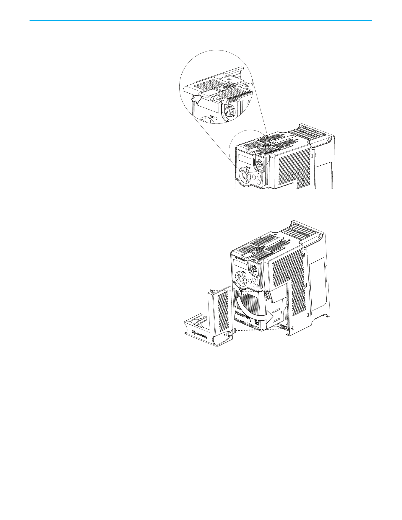
Chapter 1 Installation/Wiring
Rockwell Automation Publication 520-UM001N-EN-E - July 2024 31
2. Push the top cover of the Control Module towards the Power Module to
lock it.
3. Insert the catch at the top of the frame cover into the Power Module,
then swing the frame cover to snap the side catches onto the Power
Module (Frames B…E only).
Control Module Cover
To access the control terminals, DSI port, and Ethernet port, the front cover
must be removed. To remove:
1. Press and hold down the arrow on the front of the cover.
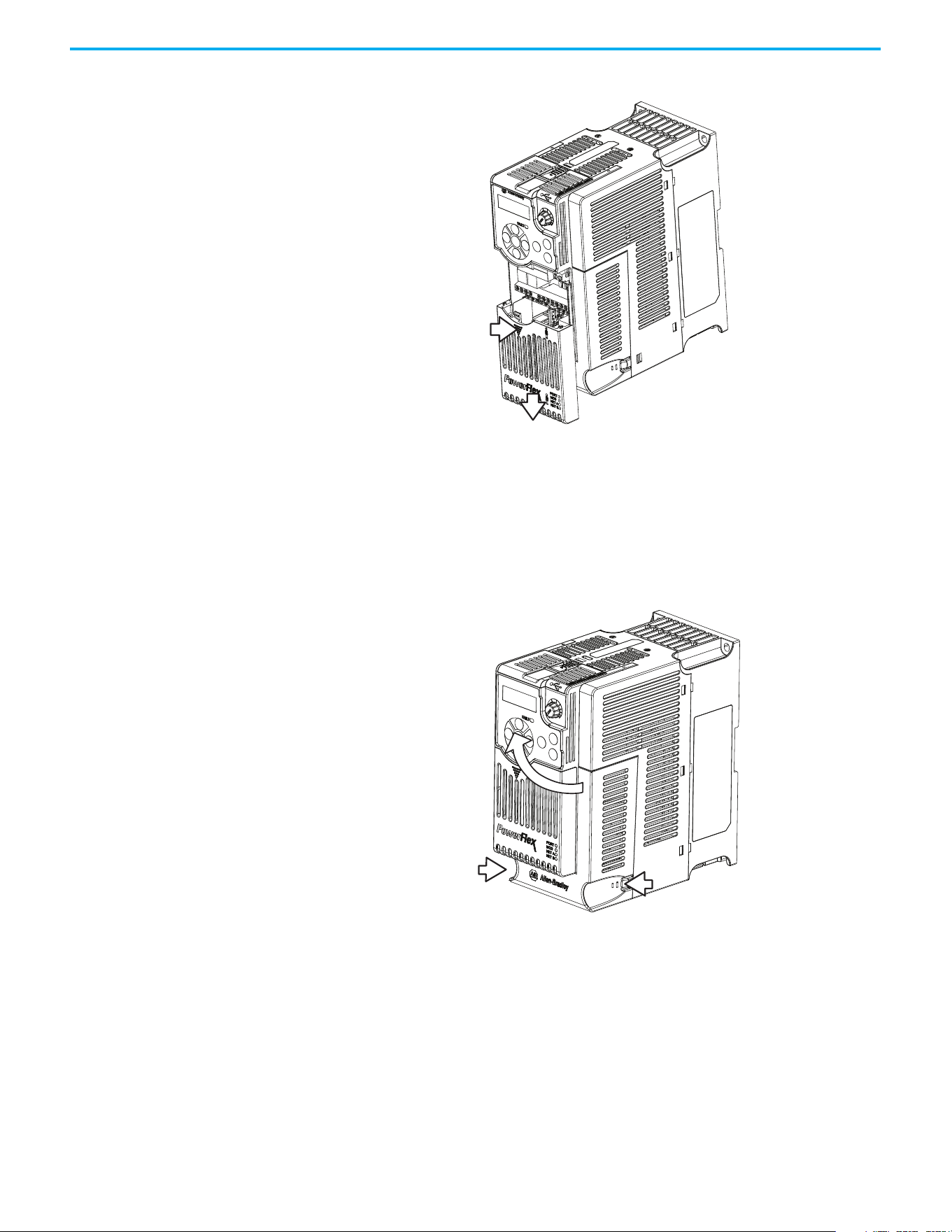
Chapter 1 Installation/Wiring
32 Rockwell Automation Publication 520-UM001N-EN-E - July 2024
2. Slide the front cover down to remove from the Control Module.
Reattach the front cover when wiring is complete.
Power Module Terminal
Guard
To access the power terminals, the terminal guard must be removed. To
remove:
1. Press and hold down the catch on both sides of the frame cover, then
pull out and swing upwards to remove (Frames B…E only).
2. Press and hold down the locking tab on the terminal guard.
1
2
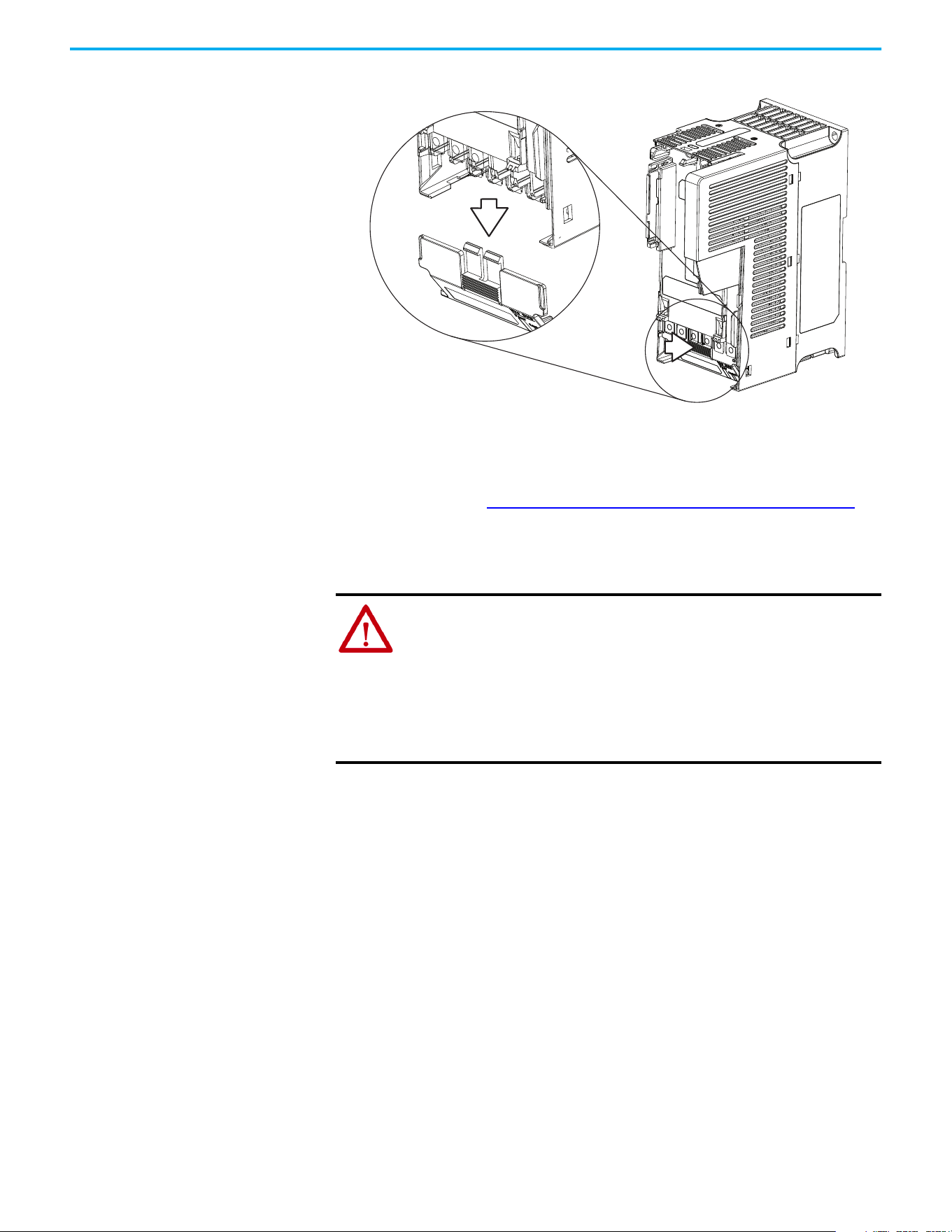
Chapter 1 Installation/Wiring
Rockwell Automation Publication 520-UM001N-EN-E - July 2024 33
3. Slide the terminal guard down to remove from the Power Module.
Reattach the terminal guard when wiring is complete.
To access the power terminals for Frame A, you must separate the Power and
Control Modules. See Separating the Power and Control Module on page 29
for
instructions.
Power Wiring
Motor Cable Types Acceptable for 100…600 Volt Installations
Various cable types are acceptable for drive installations. For many
installations, unshielded cable is adequate, provided it can be separated from
sensitive circuits. As an approximate guide, allow a spacing of 0.3 m (1 ft) for
every 10 m (32.8 ft) of length. In all cases, long parallel runs must be avoided.
Do not use cable with an insulation thickness less than 15 mils (0.4 mm/0.015
in.). Do not route more than three sets of motor leads in a single conduit to
minimize “cross talk”. If more than three drive/motor connections per conduit
are required, shielded cable must be used.
• UL installations above 50 °C (122 °F) ambient must use 600V, 90 °C
(194 °F) wire.
• UL installations in 50 °C (122 °F) ambient must use 600V, 75 °C or 90 °C
(167 °F or 194 °F) wire.
• UL installations in 40 °C (104 °F) ambient should use 600V, 75 °C or 90 °C
(167 °F or 194 °F) wire.
ATTENTION: National Codes and standards (NEC, VDE, BSI, and so on) and
local codes outline provisions for safely installing electrical equipment.
Installation must comply with specifications regarding wire types,
conductor sizes, branch circuit protection, and disconnect devices. Failure
to do so may result in personal injury and/or equipment damage.
ATTENTION: To avoid a possible shock hazard that is caused by induced
voltages, unused wires in the conduit must be grounded at both ends. For
the same reason, if a drive sharing a conduit is being serviced or installed,
all drives using this conduit should be disabled. This helps minimize the
possible shock hazard from “cross coupled” power leads.

Chapter 1 Installation/Wiring
34 Rockwell Automation Publication 520-UM001N-EN-E - July 2024
Use copper wire only. Wire gauge requirements and recommendations are
based on 75 °C (167 °F). Do not reduce wire gauge when using higher
temperature wire.
Unshielded
THHN, THWN, or similar wire is acceptable for drive installation in dry
environments provided adequate free air space and/or conduit fill rates limits
are provided. Any wire that is chosen must have a minimum insulation
thickness of 15 mils and should not have large variations in insulation
concentricity.
Shielded/Armored Cable
Shielded cable contains all general benefits of multi-conductor cable with the
added benefit of a copper braided shield that can contain much of the noise
that is generated in the distribution system. Applications with large numbers
of drives in a similar location, imposed EMC regulations or a high degree of
communications / networking are also good candidates for shielded cable.
Shielded cable may also help reduce shaft voltage and induced bearing
currents for some applications. In addition, the increased impedance of
shielded cable may help extend the distance that the motor can be located from
the drive without the addition of motor protective devices such as terminator
networks. See Reflected Wave in the Wiring and Grounding for Pulse Width
Modulated (PWM) AC Drives Installation Instructions,
publication DRIVES-IN001
.
Consideration should be given to all general specifications dictated by the
environment of the installation, including temperature, flexibility, moisture
characteristics, and chemical resistance. In addition, a braided shield should
be included and be specified by the cable manufacturer as having coverage of
at least 75%. An additional foil shield can greatly improve noise containment.
A good example of recommended cable is Belden 295xx (xx determines gauge).
This cable has four XLPE insulated conductors with a 100% coverage foil and
an 85% coverage copper braided shield (with drain wire) surrounded by a
PVC jacket.
Other types of shielded cable are available, but the selection of these types may
limit the allowable cable length. Particularly, some of the newer cables twist
four conductors of THHN wire and wrap them tightly with a foil shield. This
construction can greatly increase the cable charging current required and
reduce the overall drive performance. Unless specified in the individual
WARNING: The distance between the drive and motor must not exceed the
maximum cable length that is stated in the Motor Cable Length Restrictions
Tables in the Wiring and Grounding for Pulse Width Modulated (PWM) AC Drives
Installation Instructions, publication DRIVES-IN001
.
ATTENTION: Do not use THHN or similarly coated wire in wet areas.

Chapter 1 Installation/Wiring
Rockwell Automation Publication 520-UM001N-EN-E - July 2024 35
distance tables as tested with the drive, these cables are not recommended and
their performance against the lead length limits supplied is not known.
Reflected Wave Protection
The drive should be installed as close to the motor as possible. Installations
with long motor cables may require the addition of external devices to limit
voltage reflections at the motor (reflected wave phenomena). See Reflected
Wave in the Wiring and Grounding for Pulse Width Modulated (PWM) AC
Drives Installation Instructions, publication DRIVES-IN001
.
The reflected wave data applies to all carrier frequencies 2…16 kHz.
For 240V ratings and lower, reflected wave effects do not need to be
considered.
Output Disconnect
The drive is intended to be commanded by control input signals that will start
and stop the motor. A device that routinely disconnects then reapplies output
power to the motor for starting and stopping the motor should not be used. If
it is necessary to disconnect power to the motor with the drive outputting
power, an auxiliary contact should be used to simultaneously disable drive
(Aux Fault or Coast to Stop).
Recommended Shielded Wire
Location Rating/Type Description
Standard (Option 1)
600V, 90 °C (194 °F) XHHW2/RHW-2
Anixter B209500-B209507, Belden
29501-29507, or equivalent
• Four tinned copper conductors with XLPE
insulation.
• Copper braid/aluminum foil combination shield and
tinned copper drain wire.
• PVC jacket.
Standard (Option 2)
Tray rated 600V, 90 °C (194 °F)
RHH/RHW-2 Anixter OLF-7xxxxx or
equivalent
• Three tinned copper conductors with XLPE
insulation.
• 5 mil single helical copper tape (25% overlap min)
with three bare copper grounds in contact with
shield.
• PVC jacket.
Class I and II;
Division I and II
Tray rated 600V, 90 °C (194 °F)
RHH/RHW-2 Anixter 7V-7xxxx-3G or
equivalent
• Three bare copper conductors with XLPE insulation
and impervious corrugated continuously welded
aluminum armor.
• Black sunlight resistant PVC jacket overall.
• Three copper grounds on 6.0 mm
2
(10 AWG) and
smaller.
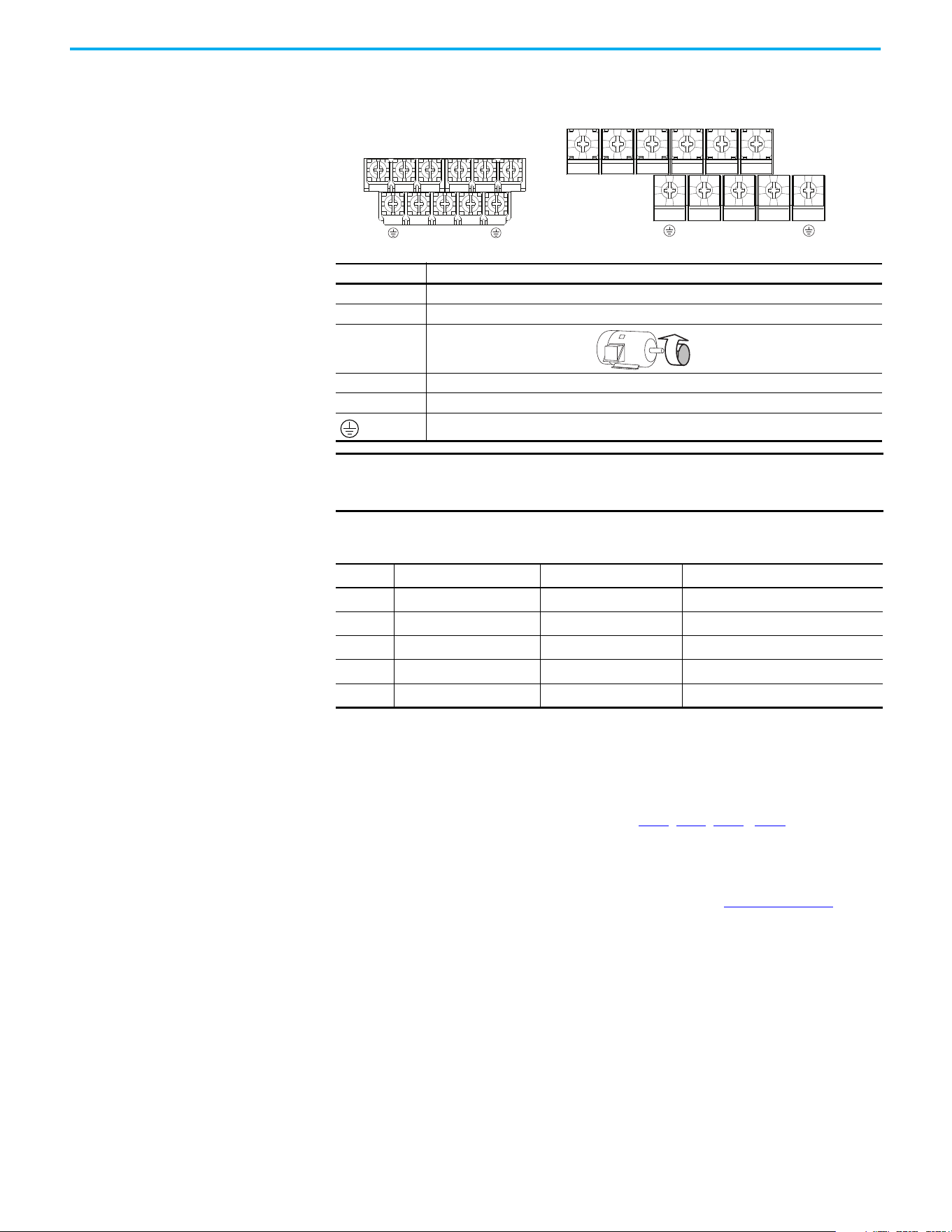
Chapter 1 Installation/Wiring
36 Rockwell Automation Publication 520-UM001N-EN-E - July 2024
Power Terminal Block
Power Terminal Block
Common Bus/Precharge
Notes
If drives are used with a disconnect switch to the common DC bus, then an
auxiliary contact on the disconnect must be connected to a digital input of the
drive. The corresponding input (parameter t062
, t063, t065…t068 [DigIn
TermBlk xx]) must be set to 30, “Precharge En” This provides the proper
precharge interlock, guarding against possible damage to the drive when
connected to a common DC bus. For more information, see Drives in Common
Bus Configurations Application Technique, publication DRIVES-AT002
.
Terminal Description
R/L1, S/L2 1-phase Input Line Voltage Connection
R/L1, S/L2, T/L3 3-phase Input Line Voltage Connection
U/T1, V/T2, W/T3 Motor Phase Connection =
Switch any two motor leads to change
forward direction.
DC+, DC- DC Bus Connection (except for 110V 1-phase)
BR+, BR- Dynamic Brake Resistor Connection
Safety Ground - PE
IMPORTANT Terminal screws may become loose during shipment. Ensure that all
terminal screws are tightened to the recommended torque before
applying power to the drive.
Power Terminal Block Wire Specifications
Frame
Maximum Wire Size
(1)
(1) Maximum/minimum sizes that the terminal block accepts. These are not recommendations.
Minimum Wire Size
(1)
Torque
A
5.3 mm
2
(10 AWG) 0.8 mm
2
(18 AWG)
1.76…2.16 N•m (15.6…19.1 lb•in)
B
8.4 mm
2
(8 AWG) 2.1 mm
2
(14 AWG)
1.76…2.16 N•m (15.6…19.1 lb•in)
C
8.4 mm
2
(8 AWG) 2.1 mm
2
(14 AWG)
1.76…2.16 N•m (15.6…19.1 lb•in)
D
13.3 mm
2
(6 AWG) 5.3 mm
2
(10 AWG)
1.76…2.16 N•m (15.6…19.1 lb•in)
E
26.7 mm
2
(3 AWG) 8.4 mm
2
(8 AWG)
3.09…3.77 N•m (27.3…33.4 lb•in)
V/T2T/L3S/L2R/L1 U/T1 W/T3
V/T2T/L3S/L2R/L1 U/T1 W/T3
BR+
BR-
DC- DC+
BR+
BR-
DC-
DC+
Frame A, B, C & D Frame E
Chapter 1 Installation/Wiring
Rockwell Automation Publication 520-UM001N-EN-E - July 2024 37
I/O Wiring
Motor Start/Stop Precautions
Important points to remember about I/O wiring:
• Always use copper wire.
• Wire with an insulation rating of 600V or greater is recommended.
• Control and signal wires should be separated from power wires by at
least 0.3 m (1 ft).
Signal and Control Wire Types
Recommendations are for 50 °C (122 °F) ambient temperature.
75 °C (167 °F) wire must be used for 60 °C (140 °F) ambient temperature.
90 °C (194 °F) wire must be used for 70 °C (158 °F) ambient temperature.
ATTENTION: A contactor or other device that routinely disconnects and
reapplies the AC line to the drive to start and stop the motor can cause drive
hardware damage. The drive is designed to use control input signals that will
start and stop the motor. If used, the input device must not exceed one
operation per minute or drive damage can occur.
ATTENTION: The drive start/stop control circuitry includes solid-state
components. If hazards due to accidental contact with moving machinery or
unintentional flow of liquid, gas or solids exist, an additional hardwired stop
circuit may be required to remove the AC line to the drive. When the AC line
is removed, there will be a loss of any inherent regenerative braking effect
that might be present - the motor will coast to a stop. An auxiliary braking
method may be required. Alternatively, use the drive’s safety input function.
IMPORTANT I/O terminals labeled “Common” are not referenced to the safety ground
(PE) terminal and are designed to greatly reduce common mode
interference.
ATTENTION: Driving the 4…20 mA analog input from a voltage source could
cause component damage. Verify proper configuration prior to applying
input signals.
Recommended Signal Wire
Signal Type/
Where Used
Belden Wire Types
(1)
(or equivalent)
(1) Stranded or solid wire.
Description
Min Insulation
Rating
Analog I/O and PTC 8760/9460
0.750 mm
2
(18 AWG), twisted-pair,
100% shield with drain
(2)
(2) If the wires are short and contained within a cabinet, which has no sensitive circuits, the use of shielded wire may not be
necessary, but is always recommended.
300V,
60 °C (140 °F)
Remote Pot 8770
0.750 mm
2
(18 AWG), 3 conductor, shielded
Encoder/Pulse I/O 9728/9730
0.196 mm
2
(24 AWG), individually shielded
pairs
Recommended Control Wire for Digital I/O
Type Wire Types Description
Min Insulation
Rating
Unshielded
Per US NEC or applicable
national or local code
—
300V,
60 °C (140 °F)
Shielded
Multi-conductor shielded
cable such as Belden
8770 (or equivalent)
0.750 mm
2
(18 AWG), 3 conductor, shielded
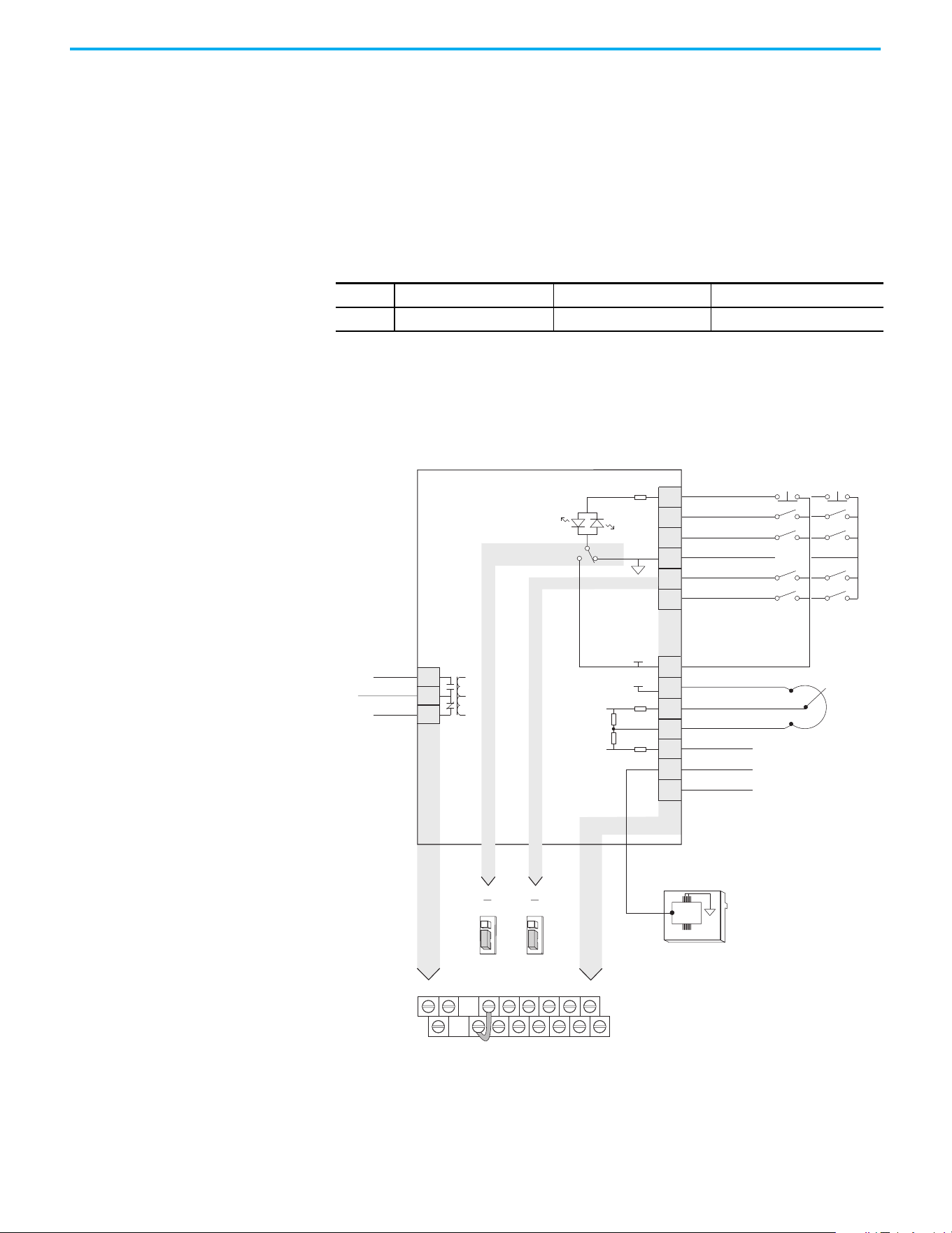
Chapter 1 Installation/Wiring
38 Rockwell Automation Publication 520-UM001N-EN-E - July 2024
Maximum Control Wire Recommendations
Do not exceed control wiring length of 30 m (100 ft). Control signal cable
length is highly dependent on electrical environment and installation
practices. To improve noise immunity, the I/O terminal block Common may be
connected to ground terminal/protective earth.
Control I/O Terminal Block
PowerFlex 523 Control I/O Terminal Block
PowerFlex 523 Series A Control I/O Wiring Block Diagram
Control I/O Terminal Block Wire Specifications
Frame
Maximum Wire Size
(1)
(1) Maximum/minimum sizes that the terminal block accepts. These are not recommendations.
Minimum Wire Size
(1)
Torque
A…E
1.3 mm
2
(16 AWG) 0.13 mm
2
(26 AWG)
0.71…0.86 N•m (6.2…7.6 lb•in)
04
05
06
01
02
03
11
12
13
14
15
C1
C2
Digital Common
DigIn TermBlk 05/Pulse
DigIn TermBlk 06
Stop
(1)
DigIn TermBlk 02/
Start/Run FWD
(2)
DigIn TermBlk 03/
Direction/Run REV
R1
R2
Relay N.O.
Relay Common
+24V DC
+10V DC
0-10V Input
Analog Common
4-20mA Input
RJ45 Shield
Comm Common
+24V
+10V
Typical
SNK wiring
Typical
SRC wiring
R1
11
12 13 14 15 C1 C2
R2
R3
01 02 03 04 05 06
Pot must be
1...10 k ohm
2 W min.
SNK
Digital In
DigIn TermBlk 05 Sel
J7J8
Pulse In
SRC Digital
Input
SRCSNK
R3
Relay N.C.
81
RS485
(DSI)
Series A
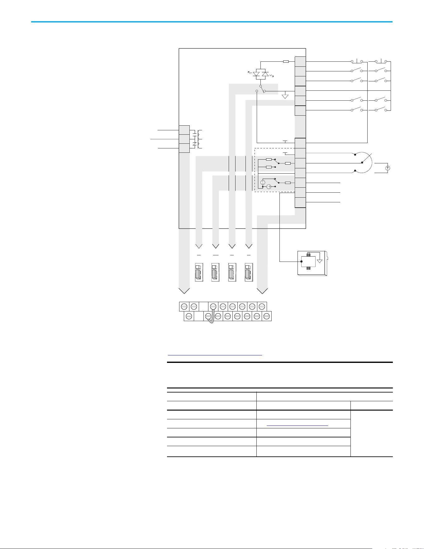
Chapter 1 Installation/Wiring
Rockwell Automation Publication 520-UM001N-EN-E - July 2024 39
PowerFlex 523 Series B Control I/O Wiring Block Diagram
Control I/O Wiring Block Diagram Notes
(1) See Digital Input Selection for Start Source on page 50 for more information on configuring the digital inputs.
IMPORTANT I/O Terminal 01 is always a stop input. The stopping mode is
determined by the drive setting. See the tables below for more
information.
Start Method Stop Method
P046, P048, P050 [Start Source x] I/O Terminal 01 Stop Normal Stop
1 “Keypad” Coast
Per P045
[Stop Mode]
2 “DigIn TrmBlk” See t062, t063 [DigIn TermBlk xx]
below
3 “Serial/DSI” Coast
4 “Network Opt” Coast
5 “EtherNet/IP”
(1)
(1) Setting is specific to PowerFlex 525 drives only.
Coast
04
05
06
01
02
03
11
12
13
14
15
C1
C2
Digital Common
DigIn TermBlk 05/Pulse
DigIn TermBlk 06
Stop
(1)
DigIn TermBlk 02/
Start/Run FWD
(2)
DigIn TermBlk 03/
Direction/Run REV
R1
R2
Relay N.O.
Relay Common
+24V DC
+10V DC
Analog Input
Analog Common
Analog Output
(3)
RJ45 Shield
Comm Common
+24V
+10V
Typical
SNK wiring
Typical
SRC wiring
R1
11
12 13 14 15 C1 C2
R2
R3
01 02 03 04 05 06
Pot must be
(4)
1...10 k ohm
2 W min.
4-20 mA
source
13
14
SNK
Digital In
DigIn TermBlk 05 Sel
J7J8
Pulse In
SRC Digital
Input
SRCSNK
R3
Relay N.C.
0/4-20 mA
Analog Out
J13
0-10V
4-20 mA
Analog In
J4
0-10V
81
RS485
(DSI)
0-10V
4-20 mA
0-10V
0/4-20 mA
Series B
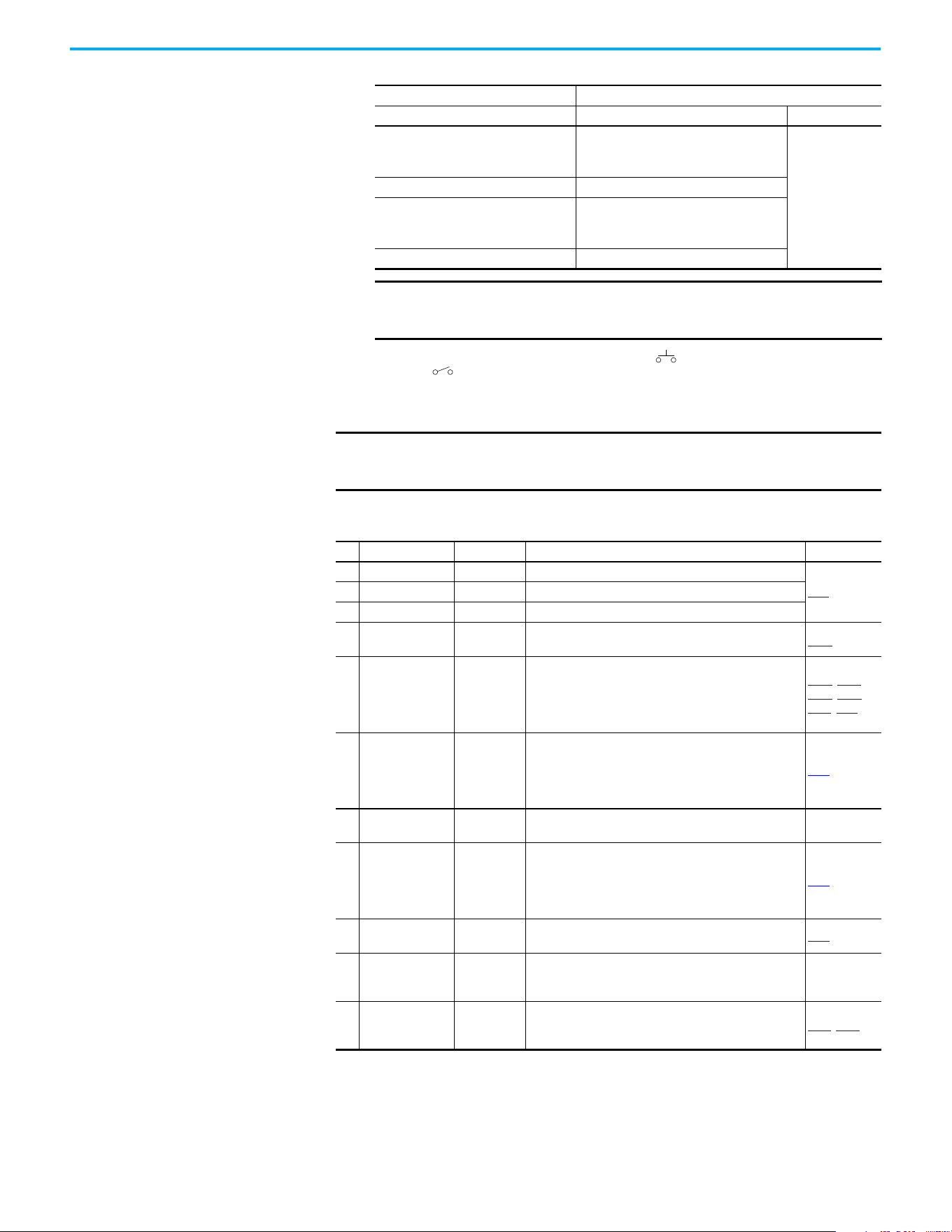
Chapter 1 Installation/Wiring
40 Rockwell Automation Publication 520-UM001N-EN-E - July 2024
(2) Two wire control shown. For three wire control use a momentary input on I/O Terminal 02 to command a start. Use a
maintained input for I/O Terminal 03 to change direction.
(3) Analog output (terminal 15) is only available on PowerFlex 523 Series B drive, and requires firmware 3.001 and later to
configure the analog output parameters (t088, t089, and t090).
(4) Potentiometer connection is only applicable when the 0
…10V setting (default) is selected for jumper J4.
Start Method Stop Method
t062, t063 [DigIn TermBlk xx] I/O Terminal 01 Stop Normal Stop
48 “2-Wire FWD”
t064 [2-Wire Mode] is set to:
• 0, 1, or 2 = Coast
• 3 = per P045 [Stop Mode]
Per P045
[Stop Mode]
49 “3-Wire Start” Per P045 [Stop Mode]
50 “2-Wire REV”
t064 [2-Wire Mode] is set to:
• 0, 1, or 2 = Coast
• 3 = per P045 [Stop Mode]
51 “3-Wire Dir” Per P045 [Stop Mode]
IMPORTANT The drive is shipped with a jumper that is installed between I/O
Terminals 01 and 11. Remove this jumper when using I/O Terminal
01 as a stop or enable input.
IMPORTANT
Only one analog frequency source may be connected at a time. If
more than one reference is connected at the same time, an
undetermined frequency reference results.
Control I/O Terminal Designations
No. Signal Default Description Parameter
R1 Relay N.O. Fault Normally open contact for output relay.
t076
R2 Relay Common Fault Common for output relay.
R3 Relay N.C. Fault Normally closed contact for output relay.
01 Stop Coast
Three wire stop. However, it functions as a stop under all
input modes and cannot be disabled.
P045
(1)
02
DigIn TermBlk 02/
Start/Run FWD
Run FWD
Used to initiate motion and also can be used as a
programmable digital input. It can be programmed with
t062 [DigIn TermBlk 02] as three wire (Start/Dir with Stop)
or two wire (Run FWD/Run REV) control. Current
consumption is 6 mA.
P045, P046,
P048, P050,
A544, t062
03
DigIn TermBlk 03/
Dir/Run REV
Run REV
Used to initiate motion and also can be used as a
programmable digital input. It can be programmed with
t063 [DigIn TermBlk 03] as three wire (Start/Dir with Stop)
or two wire (Run FWD/Run REV) control. Current
consumption is 6 mA.
t063
04 Digital Common —
Return for digital I/O. Electrically isolated (along with the
digital I/O) from the rest of the drive.
–
05
DigIn TermBlk 05/
Pulse In
Preset Freq
Program with t065 [DigIn TermBlk 05].
Also functions as a Pulse Train input for reference or
speed feedback. Requires an NPN pulse input. The
maximum frequency is 100 kHz. Current consumption is
6 mA.
t065
06 DigIn TermBlk 06 Preset Freq
Program with t066 [DigIn TermBlk 06].
Current consumption is 6 mA.
t066
11 +24V DC —
Referenced to Digital Common.
Drive supplied power for digital inputs.
Maximum output current is 100 mA.
–
12 +10V DC —
Referenced to Analog Common.
Drive supplied power for 0…10V external potentiometer.
Maximum output current is 15 mA.
P047
, P049
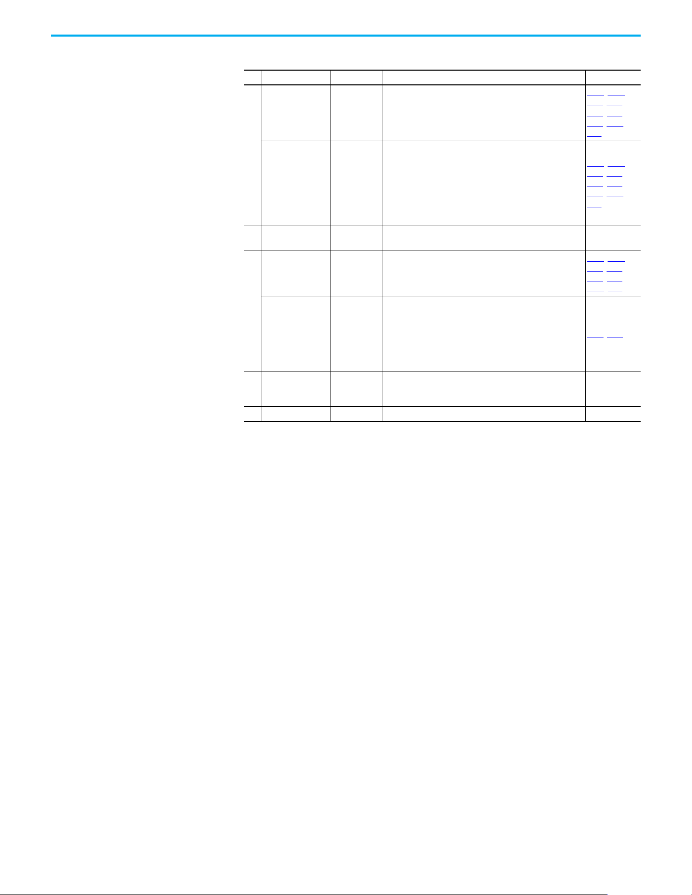
Chapter 1 Installation/Wiring
Rockwell Automation Publication 520-UM001N-EN-E - July 2024 41
13
For Series A
0…10V In
(2)
Not Active
For external 0…10V (unipolar) input supply or
potentiometer wiper.
Input impedance:
Voltage source = 100 kΩ
Allowable potentiometer resistance range = 1…10 kΩ
P047, P049,
t062, t063,
t065, t066,
t093, A459,
A471
For Series B
Analog Input
Not Active
External analog input supply, selectable by Analog Input
jumper. Default is 0…10V (unipolar) input supply or
potentiometer wiper.
Input impedance:
Voltage source = 100 kΩ
Allowable potentiometer resistance range = 1…10 kΩ
Change Analog Input jumper to 4…20 mA for external
4…20 mA input supply. Input impedance = 250 Ω
P047
, P049,
t062
, t063,
t065, t066,
t093, A459,
A471
14 Analog Common —
Return for the analog I/O. Electrically isolated (along with
the analog I/O) from the rest of the drive.
–
15
For Series A
4…20 mA In
(2)
Not Active
For external 4…20 mA input supply.
Input impedance = 250 Ω
P047, P049,
t062, t063,
t065, t066,
A459, A471
For Series B
Analog Output
OutFreq 0…10
The default analog output is 0…10V. To convert a current
value, change the Analog Output jumper to 0…20 mA.
Program with t088 [Analog Out Sel]. Maximum analog
value can be scaled with t089 [Analog Out High].
Maximum Load:
4…20 mA = 525 Ω (10.5V)
0…10V = 1 kΩ (10 mA)
t088, t089
C1 C1 —
This terminal is tied to the RJ45 port shield. Tie this
terminal to a clean ground to improve noise immunity
when using external communication peripherals.
–
C2 C2 — This is the signal common for the communication signals. –
(1) Setting is specific to PowerFlex 525 drives only.
(2) Only one analog frequency source may be connected at a time. If more than one reference is connected at the same time, an
undetermined frequency reference results.
Control I/O Terminal Designations (Continued)
No. Signal Default Description Parameter
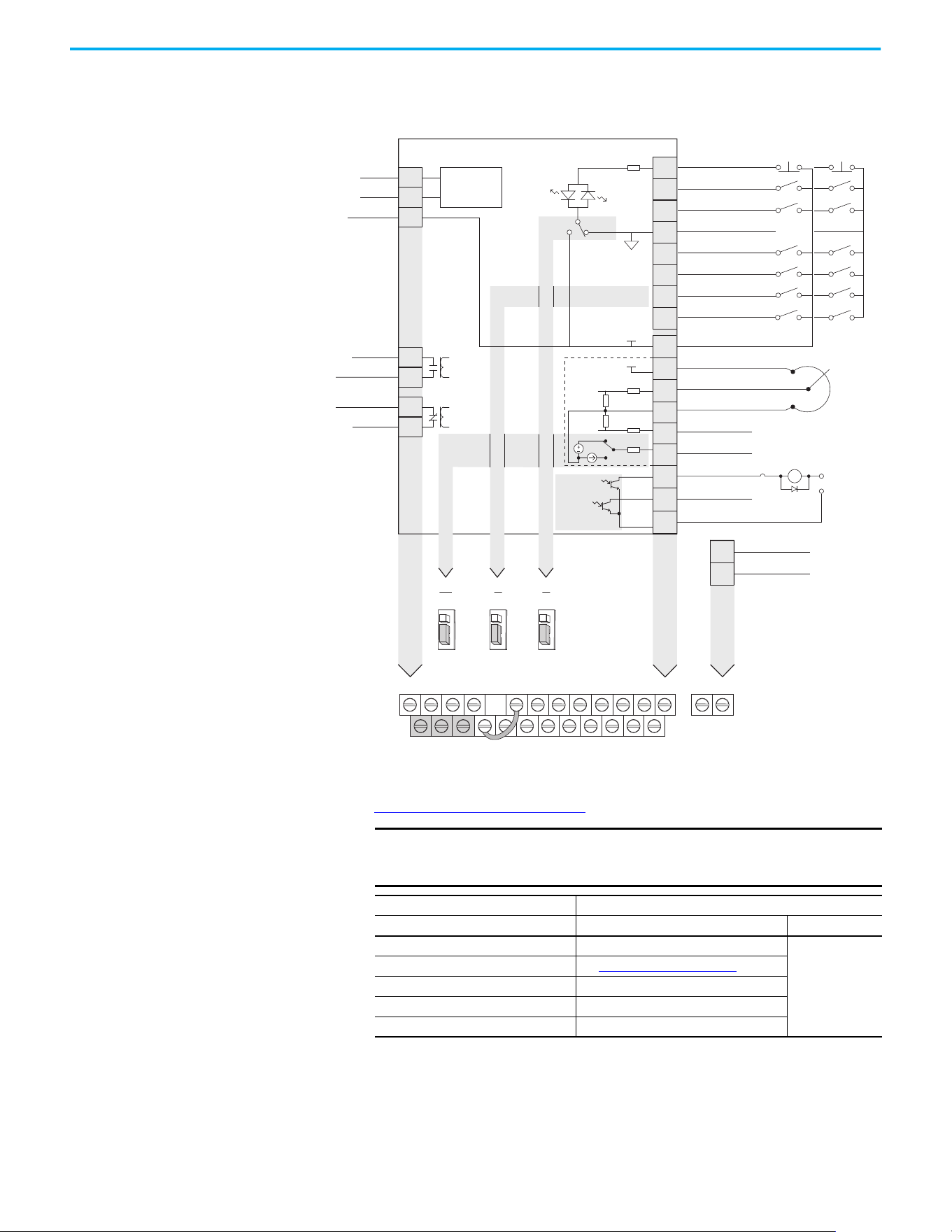
Chapter 1 Installation/Wiring
42 Rockwell Automation Publication 520-UM001N-EN-E - July 2024
PowerFlex 525 Control I/O Terminal Block
PowerFlex 525 Control I/O Wiring Block Diagram
Control I/O Wiring Block Diagram Notes
(1) See Digital Input Selection for Start Source on page 50 for more information on configuring the digital inputs.
IMPORTANT I/O Terminal 01 is always a stop input. The stopping mode is
determined by the drive setting. See the tables below for more
information.
Start Method Stop Method
P046, P048, P050 [Start Source x] I/O Terminal 01 Stop Normal Stop
1 “Keypad” Coast
Per P045
[Stop Mode]
2 “DigIn TrmBlk” See t062, t063 [DigIn TermBlk xx]
below
3 “Serial/DSI” Coast
4 “Network Opt” Coast
5 “EtherNet/IP” Coast
04
05
06
07
01
02
03
08
11
12
13
14
15
16
17
18
19
Digital Common
DigIn TermBlk 05
DigIn TermBlk 06
DigIn TermBlk 07/Pulse
Stop
(1)
DigIn TermBlk 02/
Start/Run FWD
(2)
DigIn TermBlk 03/
Direction/Run REV
DigIn TermBlk 08
R1
R2
S1
S2
S+
Relay 1 N.O.
Relay 1 Common
+24V DC
+10V DC
0-10V (or ±10V) Input
Analog Common
4-20mA Input
Analog Output
Opto Output 1
Opto Output 2
RJ45 Shield
Comm Common
Opto Common
+24V
+10V
Safety 1
Safety 2
Safety +24V
Typical
SNK wiring
Typical
SRC wiring
R1
S1 S2 S+ 11 12 13 14 15 16 17 18 19
R2 R5 R6 01 02 03 04 05 06 07 08 C1 C2
30V DC
50 mA
Non-inductive
Common
24V
(3)
Pot must be
1...10 k ohm
2 W min.
0-10V
0/4-20 mA
SNK
Digital In
DigIn TermBlk 07 Sel
Analog Out
J10 J9 J5
Pulse In
SRCDigital
Input
0/4-20mA
0-10V
SRCSNK
R5
R6
Relay 2 Common
Relay 2 N.C.
C1
C2
Safe-Torque-O
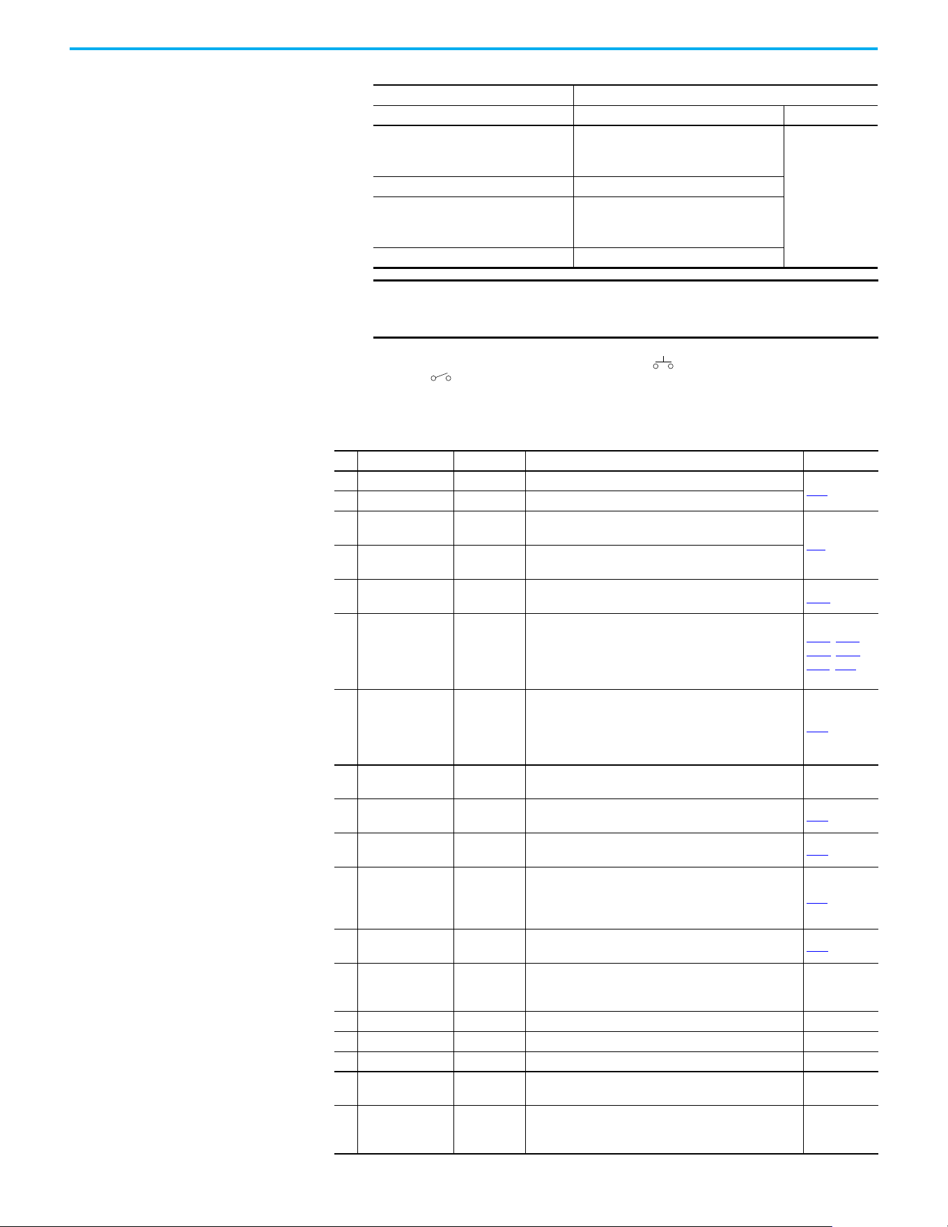
Chapter 1 Installation/Wiring
Rockwell Automation Publication 520-UM001N-EN-E - July 2024 43
(2) Two wire control shown. For three wire control use a momentary input on I/O Terminal 02 to command a start. Use a
maintained input for I/O Terminal 03 to change direction.
(3) When using an opto output with an inductive load such as a relay, install a recovery diode parallel to the relay as shown, to
prevent damage to the output.
Start Method Stop Method
t062, t063 [DigIn TermBlk xx] I/O Terminal 01 Stop Normal Stop
48 “2-Wire FWD”
t064 [2-Wire Mode] is set to:
• 0, 1, or 2 = Coast
• 3 = per P045 [Stop Mode]
Per P045
[Stop Mode]
49 “3-Wire Start” Per P045 [Stop Mode]
50 “2-Wire REV”
t064 [2-Wire Mode] is set to:
• 0, 1, or 2 = Coast
• 3 = per P045 [Stop Mode]
51 “3-Wire Dir” Per P045 [Stop Mode]
IMPORTANT The drive is shipped with a jumper that is installed between I/O
Terminals 01 and 11. Remove this jumper when using I/O Terminal
01 as a stop or enable input.
Control I/O Terminal Designations
No. Signal Default Description Parameter
R1 Relay 1 N.O. Fault Normally open contact for output relay.
t076
R2 Relay 1 Common Fault Common for output relay.
R5 Relay 2 Common
Motor
Running
Common for output relay.
t081
R6 Relay 2 N.C.
Motor
Running
Normally closed contact for output relay.
01 Stop Coast
Three wire stop. However, it functions as a stop under all
input modes and cannot be disabled.
P045
(1)
02
DigIn TermBlk 02/
Start/Run FWD
Run FWD
Used to initiate motion and also can be used as a
programmable digital input. It can be programmed with
t062 [DigIn TermBlk 02] as three wire (Start/Dir with Stop)
or two wire (Run FWD/Run REV) control. Current
consumption is 6 mA.
P045, P046,
P048, P050,
A544, t062
03
DigIn TermBlk 03/
Dir/Run REV
Run REV
Used to initiate motion and also can be used as a
programmable digital input. It can be programmed with
t063 [DigIn TermBlk 03] as three wire (Start/Dir with Stop)
or two wire (Run FWD/Run REV) control. Current
consumption is 6 mA.
t063
04 Digital Common –
Return for digital I/O. Electrically isolated (along with the
digital I/O) from the rest of the drive.
–
05 DigIn TermBlk 05 Preset Freq
Program with t065 [DigIn TermBlk 05].
Current consumption is 6 mA.
t065
06 DigIn TermBlk 06 Preset Freq
Program with t066 [DigIn TermBlk 06].
Current consumption is 6 mA.
t066
07
DigIn TermBlk 07/
Pulse In
Start Source
2 + Speed
Reference2
Program with t067 [DigIn TermBlk 07].
Also functions as a Pulse Train input for reference or
speed feedback. Requires an NPN pulse input. Maximum
frequency is 100 kHz. Current consumption is 6 mA.
t067
08 DigIn TermBlk 08 Jog Forward
Program with t068 [DigIn TermBlk 08].
Current consumption is 6 mA.
t068
C1 C1 –
This terminal is tied to the RJ45 port shield. Tie this
terminal to a clean ground to improve noise immunity
when using external communication peripherals.
–
C2 C2 – This is the signal common for the communication signals. –
S1 Safety 1 – Safety input 1. Current consumption is 6 mA. –
S2 Safety 2 – Safety input 2. Current consumption is 6 mA. –
S+ Safety +24V –
+24V supply for safety circuit. Internally tied to the +24V
DC source (Pin 11).
–
11 +24V DC –
Referenced to Digital Common.
Drive supplied power for digital inputs.
Maximum output current is 100 mA.
–
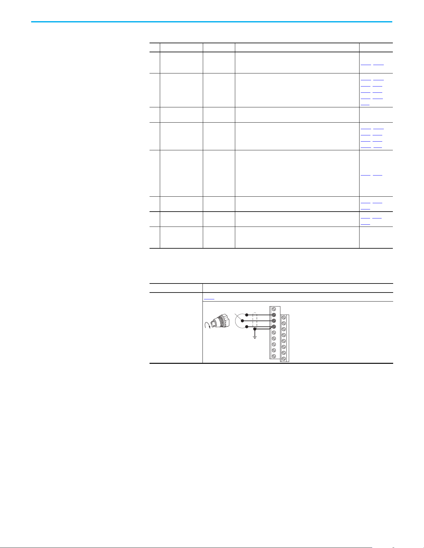
Chapter 1 Installation/Wiring
44 Rockwell Automation Publication 520-UM001N-EN-E - July 2024
12 +10V DC –
Referenced to Analog Common.
Drive supplied power for 0…10V external potentiometer.
Maximum output current is 15 mA.
P047, P049
13 ±10V In Not Active
For external 0…10V (unipolar) or ±10V (bipolar) input
supply or potentiometer wiper.
Input impedance:
Voltage source = 100 kΩ
Allowable potentiometer resistance range = 1…10 kΩ
P047, P049,
t062, t063,
t065, t066,
t093, A459,
A471
14 Analog Common –
Return for the analog I/O. Electrically isolated (along with
the analog I/O) from the rest of the drive.
–
15 4…20mA In Not Active
For external 4…20 mA input supply.
Input impedance = 250 Ω
P047
, P049,
t062, t063,
t065, t066,
A459, A471
16 Analog Output OutFreq 0…10
The default analog output is 0…10V. To convert a current
value, change the Analog Output jumper to 0…20 mA.
Program with t088 [Analog Out Sel]. Maximum analog
value can be scaled with t089 [Analog Out High].
Maximum Load:
4…20 mA = 525 Ω (10.5V)
0…10V = 1 kΩ (10 mA)
t088, t089
17 Opto Output 1
Motor
Running
Program with t069 [Opto Out1 Sel].
Each Opto-Output is rated 30V DC 50 mA (Non-inductive).
t069, t070,
t075
18 Opto Output 2 At Frequency
Program with t072 [Opto Out2 Sel].
Each Opto-Output is rated 30V DC 50 mA (Non-inductive).
t072, t073,
t075
19 Opto Common –
The emitters of the Optocoupler Outputs (1 and 2) are tied
together at Optocoupler Common. Electrically isolated
from the rest of the drive.
–
(1) Setting is specific to PowerFlex 525 drives only.
I/O Wiring Examples
I/O Connection Example
Potentiometer
1...10 kΩ Pot.
Recommended
(2 W minimum)
P047
[Speed Reference1] = 5 “0-10V Input”
Control I/O Terminal Designations (Continued)
No. Signal Default Description Parameter
12
13
14
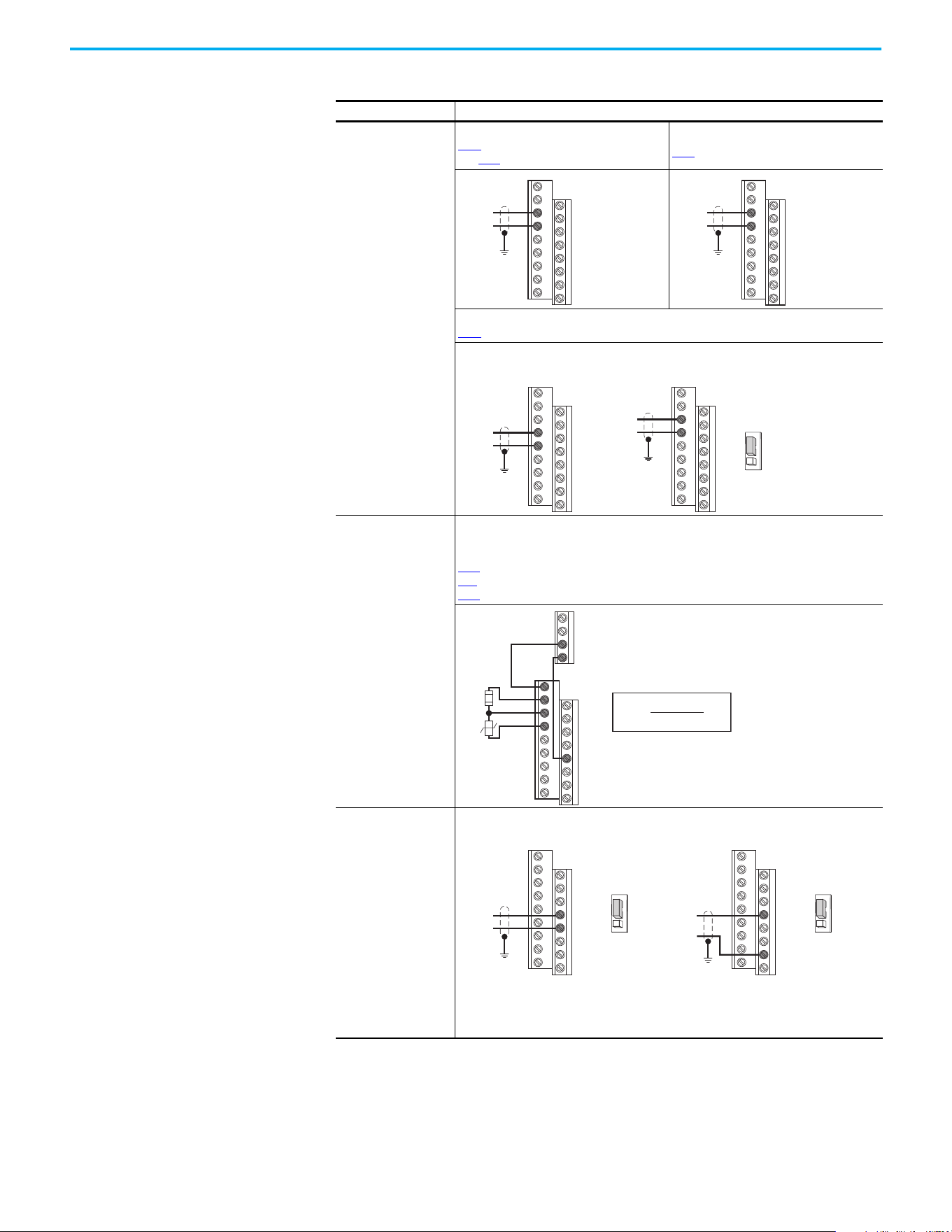
Chapter 1 Installation/Wiring
Rockwell Automation Publication 520-UM001N-EN-E - July 2024 45
Analog Input
0…10V, 100 kΩ
impedance
4…20 mA, 250 Ω
impedance
Bipolar
P047
[Speed Reference1] = 5 “0-10V Input”
and t093 [10V Bipolar Enbl] = 1 “Bi-Polar In”
Unipolar (Voltage)
P047 [Speed Reference1] = 5 “0-10V Input”
Unipolar (Current)
P047
[Speed Reference1] = 6 “4-20mA Input”
Analog Input, PTC
For Drive Fault
Wire the PTC and External Resistor (typically matched to the PTC Hot Resistance) to I/O
Terminals 12, 13, 14.
Wire R2/R3 Relay Output (SRC) to I/O Terminals 5 & 11.
t065
[DigIn TermBlk 05] = 12 “Aux Fault”
t081 [Relay Out 2 Sel] = 10 “Above Anlg V”
t082 [Relay Out 2 Level] = % Voltage Trip
Pulse Train Input
PowerFlex 523
t065 [DigIn TermBlk 05]
= 52
PowerFlex 525
t067 [DigIn TermBlk 07]
= 52
Use P047, P049, and
P051 [Speed
Referencex] to select
pulse input.
Jumper for DigIn
TermBlk 05 or 07 Sel
must be moved to Pulse
In.
I/O Wiring Examples (Continued)
I/O (Continued) Connection Example
13
14
±10V
Common
13
14
+
Common
14
15
Common
+
13
14
+
Common
PowerFlex 523 Series BPowerFlex 523 Series A,
PowerFlex 525
4-20 mA
Analog In
0-10V
11
12
13
14
R5
R6
05
%V
Trip
= X 100
R
PTC (hot)
R
PTC (hot)
+ R
e
R
e
R
PTC
Common
PowerFlex 523 PowerFlex 525
Pulse In
05
04
DigIn TermBlk 05 Sel
Pulse In
Digital
Input
Common
Pulse In
07
04
DigIn TermBlk 07 Sel
Pulse In
Digital
Input
The device connected to terminal 5 (for PowerFlex 523) or terminal 7 (for PowerFlex 525)
needs to be NPN or push-pull output driver.
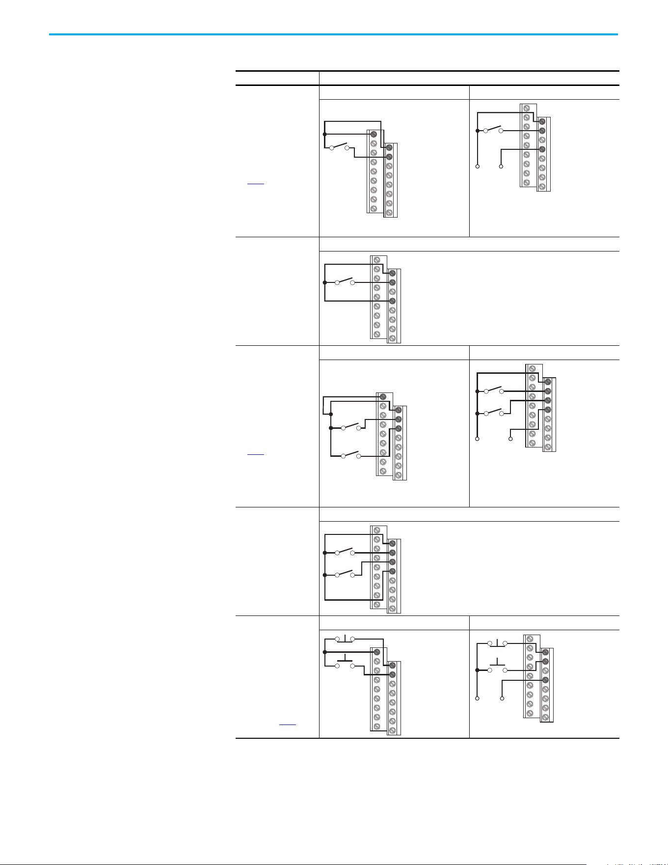
Chapter 1 Installation/Wiring
46 Rockwell Automation Publication 520-UM001N-EN-E - July 2024
2-wire SRC Control -
Nonreversing
P046 [Start Source 1] =
2 and t062 [DigIn
TermBlk 02] = 48
Input must be active for
the drive to run. When
input is opened, the
drive stops as specified
by P045 [Stop Mode].
If desired, a User
Supplied 24V DC power
source can be used.
See the “External
Supply (SRC)” example.
Internal Supply (SRC) External Supply (SRC)
Each digital input draws 6 mA.
2-wire SNK Control -
Nonreversing
Internal Supply (SNK)
2-wire SRC Control -
Run FWD/Run REV
P046 [Start Source 1] =
2, t062 [DigIn TermBlk
02] = 48 and t063
[DigIn TermBlk 03] = 50
Input must be active for
the drive to run. When
input is opened, the
drive stops as specified
by P045
[Stop Mode].
If both Run Forward and
Run Reverse inputs are
closed at the same
time, an undetermined
state could occur.
Internal Supply (SRC) External Supply (SRC)
Each digital input draws 6 mA.
2-wire SNK Control -
Run FWD/Run REV
Internal Supply (SNK)
3-wire SRC Control -
Nonreversing
P046 [Start Source 1] =
2, t062 [DigIn TermBlk
02] = 49 and t063
[DigIn TermBlk 03] = 51
A momentary input
starts the drive. A stop
input to I/O Terminal 01
stops the drive as
specified by P045
[Stop
Mode].
Internal Supply (SRC) External Supply (SRC)
Each digital input draws 6 mA.
I/O Wiring Examples (Continued)
I/O (Continued) Connection Example
11
01
02
Stop-Run
+24V Common
01
02
04
Stop-Run
Stop-Run
01
02
03
04
11
01
02
03
Stop-Run
Forward
Stop-Run
Reverse
Common
01
02
03
04
Stop-Run
Forward
Stop-Run
Reverse
+24V
Stop-Run
Forward
Stop-Run
Reverse
01
02
03
04
11
01
02
Stop
Start
01
02
04
+24V
Common
Stop
Start
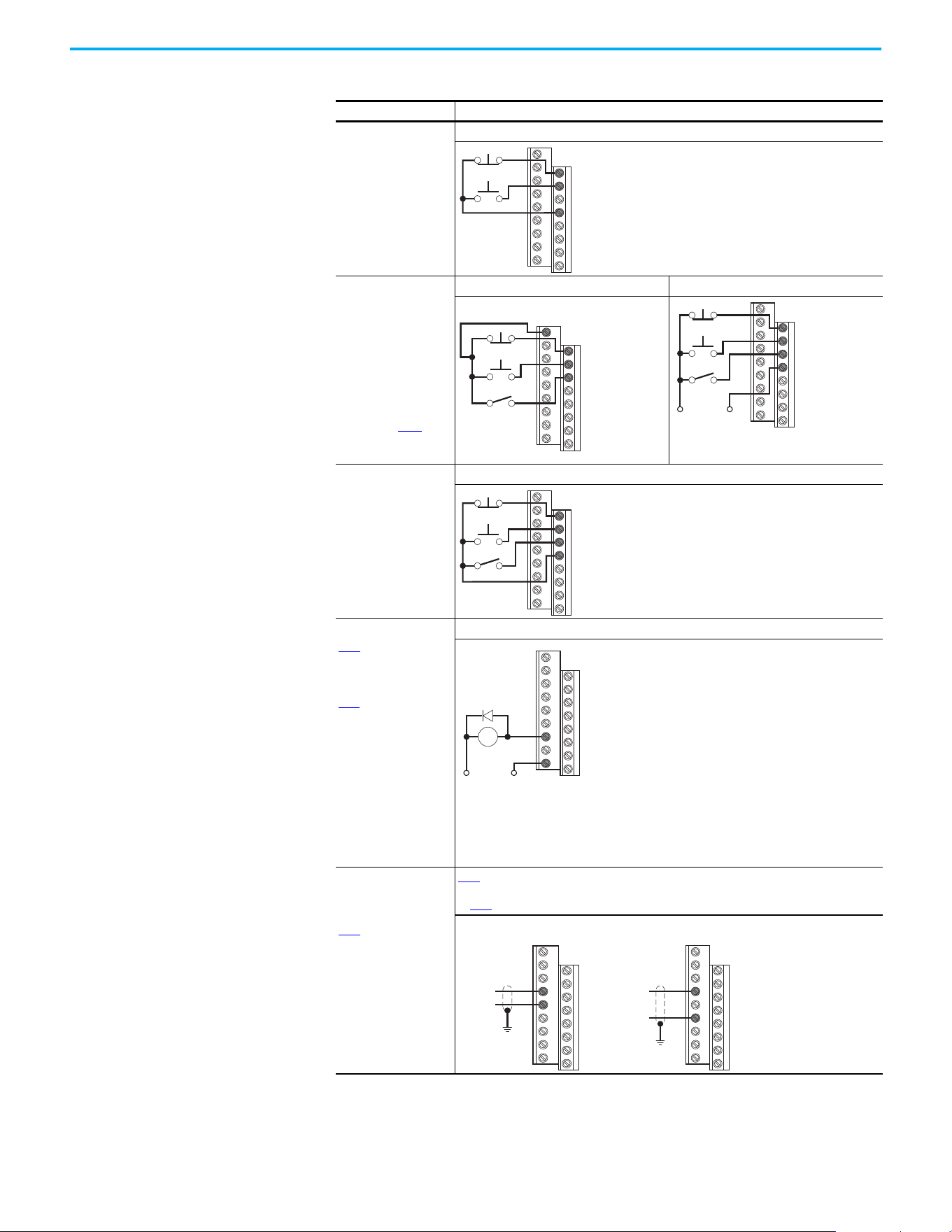
Chapter 1 Installation/Wiring
Rockwell Automation Publication 520-UM001N-EN-E - July 2024 47
3-wire SNK Control -
Nonreversing
Internal Supply (SNK)
3-wire SRC Control -
Reversing
P046 [Start Source 1] =
2, t062 [DigIn TermBlk
02] = 49 and t063
[DigIn TermBlk 03] = 51
A momentary input
starts the drive. A stop
input to I/O Terminal 01
stops the drive as
specified by P045
[Stop
Mode]. I/O Terminal 03
determines direction.
Internal Supply (SRC) External Supply (SRC)
Each digital input draws 6 mA.
3-wire SNK Control -
Reversing
Internal Supply (SNK)
Opto Output (1 & 2)
(1)
t069 [Opto Out1 Sel]
determines Opto-
Output 1 (I/O Terminal
17) operation.
t072 [Opto Out2 Sel]
determines Opto-
Output 2 (I/O Terminal
18) operation.
When using Opto-
Output with an
inductive load such as
a relay, install a
recovery diode parallel
to the relay as shown,
to prevent damage to
the output.
Opto-Output 1
Each Opto-Output is rated 30V DC 50 mA (Non-inductive).
Analog Output
(2)
t088 [Analog Out Sel]
determines analog
output type and drive
conditions.
0…10V, 1k Ω min
0…20 mA/4…20 mA,
525 Ω 0…20 mA/
4…20 mA, 525 Ω max
t088
[Analog Out Sel] = 0...23
The Analog Output Select jumper must be set to match the analog output signal mode set
in t088
[Analog Out Sel].
(1) Feature is specific to PowerFlex 525 drives only.
(2) Feature is not applicable to PowerFlex 523 series A drives.
I/O Wiring Examples (Continued)
I/O (Continued) Connection Example
Stop
Start
01
02
04
11
01
02
03
Stop
Start
Direction
+24V Common
Stop
Start
Direction
01
02
03
04
Stop
Start
Direction
01
02
03
04
Common+24V
CR
19
17
14
16
Common
+
PowerFlex 523 Series B PowerFlex 525
14
15
Common
+
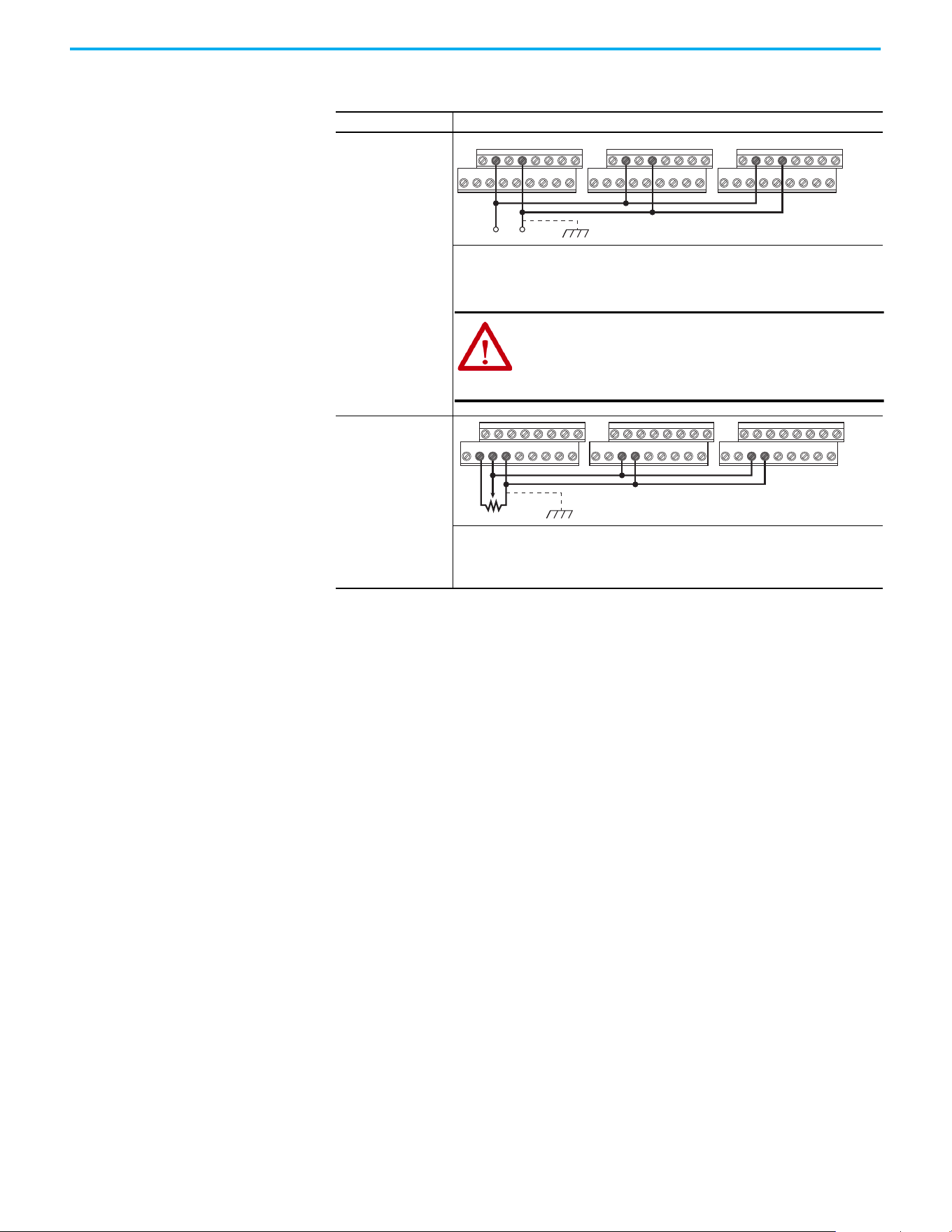
Chapter 1 Installation/Wiring
48 Rockwell Automation Publication 520-UM001N-EN-E - July 2024
Typical Multiple Drive Connection Examples
Input/Output Connection Example
Multiple Digital Input
Connections
Customer Inputs can
be wired per External
Supply (SRC).
When connecting a single input such as Run, Stop, Reverse, or Preset Speeds to multiple
drives, it is important to connect I/O Terminal 04 common together for all drives. If they
are to be tied into another common (such as earth ground or separate apparatus ground)
only one point of the daisy chain of I/O Terminal 04 should be connected.
Multiple Analog
Connections
When connecting a single potentiometer to multiple drives, it is important to connect I/O
Terminal 14 common together for all drives. I/O Terminal 14 common and I/O Terminal 13
(potentiometer wiper) should be daisy chained to each drive. All drives must be powered
up for the analog signal to be read correctly.
Customer Inputs Optional Ground Connection
04020402 0402
ATTENTION: I/O Common terminals should not be tied
together when using SNK (Internal Supply) mode. In SNK
mode, if power is removed from one drive, inadvertent
operation of other drives that share the same I/O
Common connection may occur.
Remote Potentiometer Optional Ground Connection
12 13 1413 14 13 14
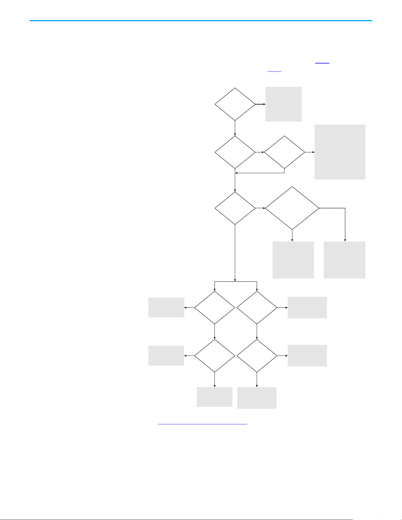
Chapter 1 Installation/Wiring
Rockwell Automation Publication 520-UM001N-EN-E - July 2024 49
Start and Speed Reference
Control
Start Source and Speed Reference Selection
The start and drive speed command can be obtained from a number of
different sources. By default, start source is determined by P046
[Start Source
1] and drive speed source is determined by P047
[Speed Reference1]. However,
various inputs can override this selection, See below for the override priority.
(1) [Start Source 2/3] and [Speed Reference2/3] can be selected by the control terminal block or communication commands.
(2) See Digital Input Selection for Start Source on page 50 for information on selecting the correct digital input.
Purge Input Enabled
AND Active
Jog Input Enabled
AND Active
Preset Inputs Active
[Speed Referencex]
= 11 or 12 (PIDx Output)
AND
[PID x Ref Sel]
= 7 (Preset Freq)
[Speed Reference3]
select
(1)
[Start Source 3]
select
(1)
[Start Source 2]
select
(1)
[Speed Reference2]
select
(1)
Drive stopped
(NOT running)
Drive will start and
run at Purge Speed.
Direction is always
FORWARD.
Drive will start and run at
Jog Speed.
Direction is from Terminal
Block REV terminal (03),
Comms,
OR
FWD/REV determined by
Jog FWD/Jog REV command.
Run as specied by
[PIDx Output].
Start and Direction
commands come from
[Start Source x].
Run as specied by
[Preset Freq x].
Start and Direction
commands come from
[Start Source x].
Run as specied by
[Speed Reference3].
Run as specied by
[Speed Reference2].
Run as specied by
[Speed Reference1].
Start and Direction
command from
[Start Source 1].
Start and Direction
command from
[Start Source 3].
(2)
No
No
No
No
No
No No
No
No
Yes
Yes Yes
Yes Yes
Yes
Yes
Yes
Start and Direction
command from
[Start Source 2].
(2)
Yes

Chapter 1 Installation/Wiring
50 Rockwell Automation Publication 520-UM001N-EN-E - July 2024
Digital Input Selection for Start Source
If P046, P048 or P050 [Start Source x] has been set to 2, “DigIn TermBlk”, then
t062
and t063 [DigIn TermBlk xx] must be configured for 2-wire or 3-wire
control for the drive to function properly.
[Start Source x]
= 2 (DigIn TrmBlk)
[DigIn TermBlk
02/03] = 48/49/50/51
(2-Wire or
3-Wire)
Drive will not start.
Start and Direction
command from
Terminal Block.
[Start Source x]
Start and Direction
command from
[Start Source x].
No No
Yes Yes

Chapter 1 Installation/Wiring
Rockwell Automation Publication 520-UM001N-EN-E - July 2024 51
Accel/Decel Selection
The Accel/Decel rate can be obtained by various methods. The default rate is
determined by P041
[Accel Time 1] and P042 [Decel Time 1].
Alternative Accel/Decel rates can be made through digital inputs,
communications and/or parameters. See below for the override priority.
(1) Setting is specific to PowerFlex 525 drives only.
Purge Input Enabled
AND Active
Terminal Block Jog
Input Enabled AND
Active
Input(s) is
programmed as
Acc/Dec
(2/3/4)
Is speed controlled
by [Preset Freq x]
Active
[Speed Referencex]
= Comms
and
[Start Source x]
= 3 “Serial/DSI” or
4 “Network Opt” or
5 “EtherNet/IP”
Active
[Speed Referencex]
= 13 (Step Logic)
(1)
Drive stopped
(NOT running)
Accel/Decel always
Accel/Decel 1.
Accel/Decel from
[Jog Acc/Dec].
Accel/Decel 2 is active
when input is selected
by Accel and Decel input.
Drive uses Accel 1
and Decel 1.
No
No
No
No
No
No
No
Yes
Yes Ye s
Yes
Yes
Yes
Yes
Accel/Decel 1/2/3/4 is
selected by the default
[Preset Freq x] setting.
Accel/Decel 1 or 2 is
selected according
to Comms.
Accel/Decel 1/2/3/4 is
selected according to
Step Logic
Active [DigIn TermBlk xx]
= 32 (Sync Enable)
[Sync Time] is used
for Accel/Decel rate
No
Yes
Traverse active if
[Max Traverse] > 0 Hz
Traverse Inc/Dec
is used for
Accel/Decel rate
No
Yes

Chapter 1 Installation/Wiring
52 Rockwell Automation Publication 520-UM001N-EN-E - July 2024
CE Conformity
Compliance with the Low Voltage Directive and Electromagnetic
Compatibility Directive has been demonstrated using harmonized European
Norm (EN) standards that are published in the Official Journal of the
European Communities. PowerFlex 520-series drives comply with the EN
standards that are listed below when installed according to the installation
instructions in this manual.
CE Declarations of Conformity are available online at rok.auto/certifications
.
Low Voltage Directive (2014/35/EU)
• EN 61800-5-1 Adjustable speed electrical power drive systems – Part 5-1:
Safety requirements – Electrical, thermal, and energy.
EMC Directive (2014/30/EU)
• EN 61800-3 – Adjustable speed electrical power drive systems - Part 3:
EMC requirements and specific test methods.
Machinery Directive (2006/42/EC)
• EN ISO 13849-1 – Safety of machinery – Safety-related parts of control
systems -Part 1: General principles for design.
• EN 62061 – Safety of machinery – Functional safety of safety-related
electrical, electronic, and programmable electronic control systems.
• EN 60204-1 – Safety of machinery – Electrical equipment of machines -
Part 1: General requirements.
• EN 61800-5-2 – Adjustable speed electrical power drive systems - Part 5-
2: Safety requirement – Functional.
See Appendix G
for installation consideration that is related to Machinery
Directive.
ATEX Directive (2014/34/EU)
• EN 50495 – Safety devices that are required for the safe functioning of
equipment with respect to explosion risks.
UKCA Conformity
Compliance with application Statutory Regulations has been demonstrated
using harmonized standards published in the UK list of Designated standards.
PowerFlex 520-series drives comply with the EN standards listed below when
installed according to the installation instructions in this manual.
UK Declarations of Conformity are available online at rok.auto/certifications
.
Pollution Degree Ratings According to EN 61800-5-1
Pollution
Degree
Description
1 No pollution or only dry, non-conductive pollution occurs. The pollution has no influence.
2
Normally, only non-conductive pollution occurs. Occasionally, however, a temporary conductivity
that is caused by condensation is to be expected, when the drive is out of operation.

Chapter 1 Installation/Wiring
Rockwell Automation Publication 520-UM001N-EN-E - July 2024 53
Electrical Equipment (Safety) Regulations (2016 No. 1101)
• EN 61800-5-1 Adjustable speed electrical power drive systems – Part 5-1:
Safety requirements – Electrical, thermal, and energy.
Electromagnetic Compatibility Regulations (2016 No. 1091)
• EN 61800-3 Adjustable speed electrical power drive systems – Part 3:
EMC requirements and specific test methods.
Supply of Machinery (Safety) Regulations (2008 No. 1597)
• EN ISO 13849-1 – Safety of machinery – Safety related parts of control
systems -Part 1: General principles for design.
• EN 62061 – Safety of machinery – Functional safety of safety-related
electrical, electronic and programmable electronic control systems.
• EN 60204-1 – Safety of machinery – Electrical equipment of machines –
Part 1: General requirements.
• EN 61800-5-2 – Adjustable speed electrical power drive systems – Part
5-2: Safety requirement – Functional.
See Appendix G
for installation consideration related to the Supply of
Machinery (Safety) Regulations.
Equipment and Protective Systems Intended for Use in Potentially
Explosive Atmospheres Regulations (2016 No. 1107)
• EN 50495 – Safety devices required for the safe functioning of
equipment with respect to explosion risks.
General Considerations
• For CE and UK compliance, drives must satisfy installation
requirements that are related to both EN 61800-5-1 and EN 61800-3
provided in this document.
• PowerFlex 520-series drives must be installed in a pollution degree 1 or
2 environment to be compliant with the CE LV Directive and UK LV
Regulations. See Pollution Degree Ratings According to EN 61800-5-1
on page 52 for descriptions of each pollution degree rating.
• PowerFlex 520-series drives comply with the EMC requirements of EN
61800-3 when installed according to good EMC practices and the
instructions that are provided in this document. However, many
factors can influence the EMC compliance of an entire machine or
installation, and compliance of the drive itself does not ensure
compliance of all applications.
Pollution Degree Ratings According to EN 61800-5-1
Pollution
Degree
Description
1 No pollution or only dry, non-conductive pollution occurs. The pollution has no influence.
2
Normally, only non-conductive pollution occurs. Occasionally, however, a temporary conductivity
that is caused by condensation is to be expected, when the drive is out of operation.

Chapter 1 Installation/Wiring
54 Rockwell Automation Publication 520-UM001N-EN-E - July 2024
• PowerFlex 520-series drives are not intended to be used on public low-
voltage networks, which supply domestic premises. Without additional
mitigation, radio frequency interference is expected if used on such a
network. The installer is responsible for taking measures such as a
supplementary line filter and enclosure (see Connections and
Grounding on page 55) to prevent interference, in addition to the
installation requirements of this document.
• PowerFlex 520-series drives generate harmonic current emissions on
the AC supply system. When operated on a public low-voltage network
it is the responsibility of the installer or user to ensure that applicable
requirements of the distribution network operator have been met.
Consultation with the network operator and Rockwell Automation may
be necessary.
• If the optional NEMA 1 kit is not installed, the drive must be installed in
an enclosure with side openings less than 12.5 mm (0.5 in.) and top
openings less than 1.0 mm (0.04 in.) to maintain compliance with the
LV Directive and UK LV Regulations.
• The motor cable should be kept as short as possible to avoid
electromagnetic emission as well as capacitive currents.
• Use of line filters in ungrounded systems is not recommended.
• In CE installations, input power must be a Balanced Wye with Center
Ground configuration for EMC compliance.
Installation Requirements Related to EN 61800-5-1 and the Low Voltage Directive/UK LV
Regulations
• 600V PowerFlex 520-series drives can only be used on a “center
grounded” supply system for altitudes up to and including 2000 m
(6562 ft).
• When used at altitudes above 2000 m (6562 ft) up to a maximum of
4800 m (15,748 ft), PowerFlex 520-series drives of voltage classes up to
480V may not be powered from a “corner-earthed” supply system to
maintain compliance with the CE LV Directive and UK LV Regulations.
See Derating Guidelines for High Altitude on page 18
.
• PowerFlex 520-series drives produce leakage current in the protective
earthing conductor, which exceeds 3.5 mA AC and/or 10 mA DC. The
minimum size of the protective earthing (grounding) conductor that is
used in the application must comply with local safety regulations for
high protective earthing conductor current equipment.
• When connected, power terminals DC+/BR+, DC-, and BR- must be
protected with a DC fuse. See Dynamic Brake Resistors on page 176
for
part numbers of the fuses.
ATTENTION: NEMA/UL Open Type drives must either be installed in a
supplementary enclosure or equipped with a “NEMA Type 1 Kit” to be
CE and UK compliant with respect to protection against electrical
shock.
ATTENTION: PowerFlex 520-series drives produce DC current in the
protective earthing conductor which may reduce the ability of RCDs
(residual current-operated protective devices) or RCMs (residual
current-operated monitoring devices) of type A or AC to provide
protection for other equipment in the installation. Where an RCD or
RCM is used for protection in case of direct or indirect contact, only
an RCD or RCM of Type B is allowed on the supply side of this product.
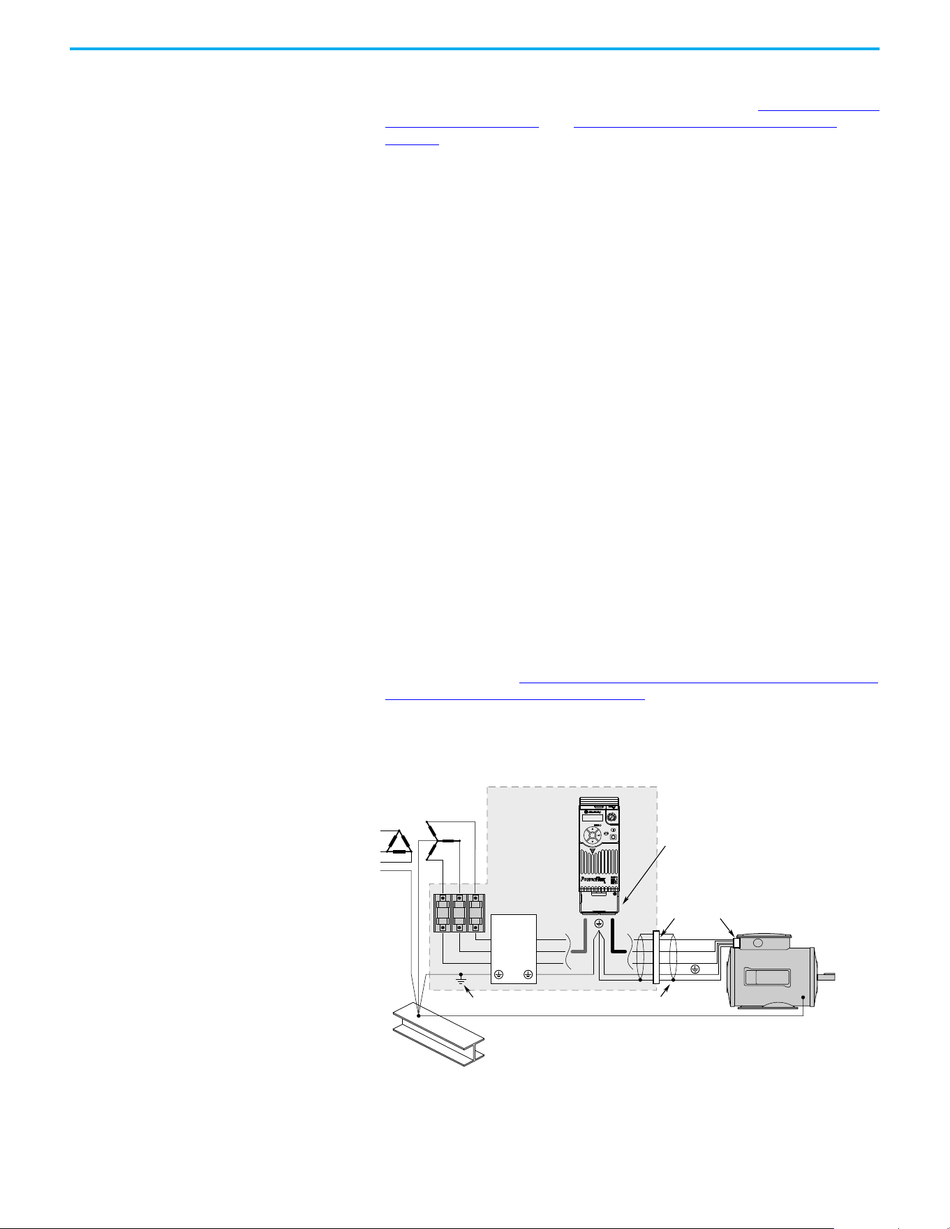
Chapter 1 Installation/Wiring
Rockwell Automation Publication 520-UM001N-EN-E - July 2024 55
Installation Requirements Related to EN 61800-3 and the EMC Directive
• The drive must be earthed (grounded) as described in Connections and
Grounding on page 55. See General Grounding Requirements on
page 20 for additional grounding recommendations.
• Output power wiring to the motor must employ cables with a braided
shield providing 75% or greater coverage, or the cables must be housed
in metal conduit, or equivalent shield must be provided. Continuous
shielding must be provided from the drive enclosure to the motor
enclosure. Both ends of the motor cable shield (or conduit) must
terminate with a low-impedance connection to earth.
Drive Frames A…E: At the drive end of the motor, either:
a. The cable shield must be clamped to a properly installed “EMC Plate”
for the drive. Kit number 25-EMC1-Fx.
or
b. The cable shield or conduit must terminate in a shielded connector
that is installed in an EMC plate, conduit box, or similar.
• At the motor end, the motor cable shield or conduit must terminate in a
shielded connector, which must be properly installed in an earthed
motor wiring box that is attached to the motor. The motor wiring box
cover must be installed and earthed.
• All control (I/O) and signal wiring to the drive must use cable with a
braided shield providing 75% or greater coverage, or the cables must be
housed in metal conduit, or equivalent shielding must be provided.
When shielded cable is used, the cable shield should be terminated with
a low impedance connection to earth at only one end of the cable,
preferably the end where the receiver is located. When the cable shield
is terminated at the drive end, it may be terminated either by using a
shielded connector in conjunction with a conduit plate or conduit box,
or the shield may be clamped to an “EMC plate.”
• Motor cabling must be separated from control and signal wiring
wherever possible.
• Maximum motor cable length must not exceed the maximum length
that is indicated in PowerFlex 520-series RF Emission Compliance and
Installation Requirements on page 56 for compliance with radio
frequency emission limits for the specific standard and installation
environment.
Connections and Grounding
(1) Some installations require a shielded enclosure. Keep wire length as short as possible between the enclosure entry point and
the EMI filter.
R/L1
S/L2
T/L3
U/T1
V/T2
W/T3
EMI ttings and metal conduit
IP 30/NEMA 1/UL Type 1
option kit or EMC kit
Shielded enclosure
(1)
Building structure steel
Enclosure ground connection
EMI lter
L1'
L2'
L3'
L1
L2
L3
Shielded motor cable
Esc
Sel
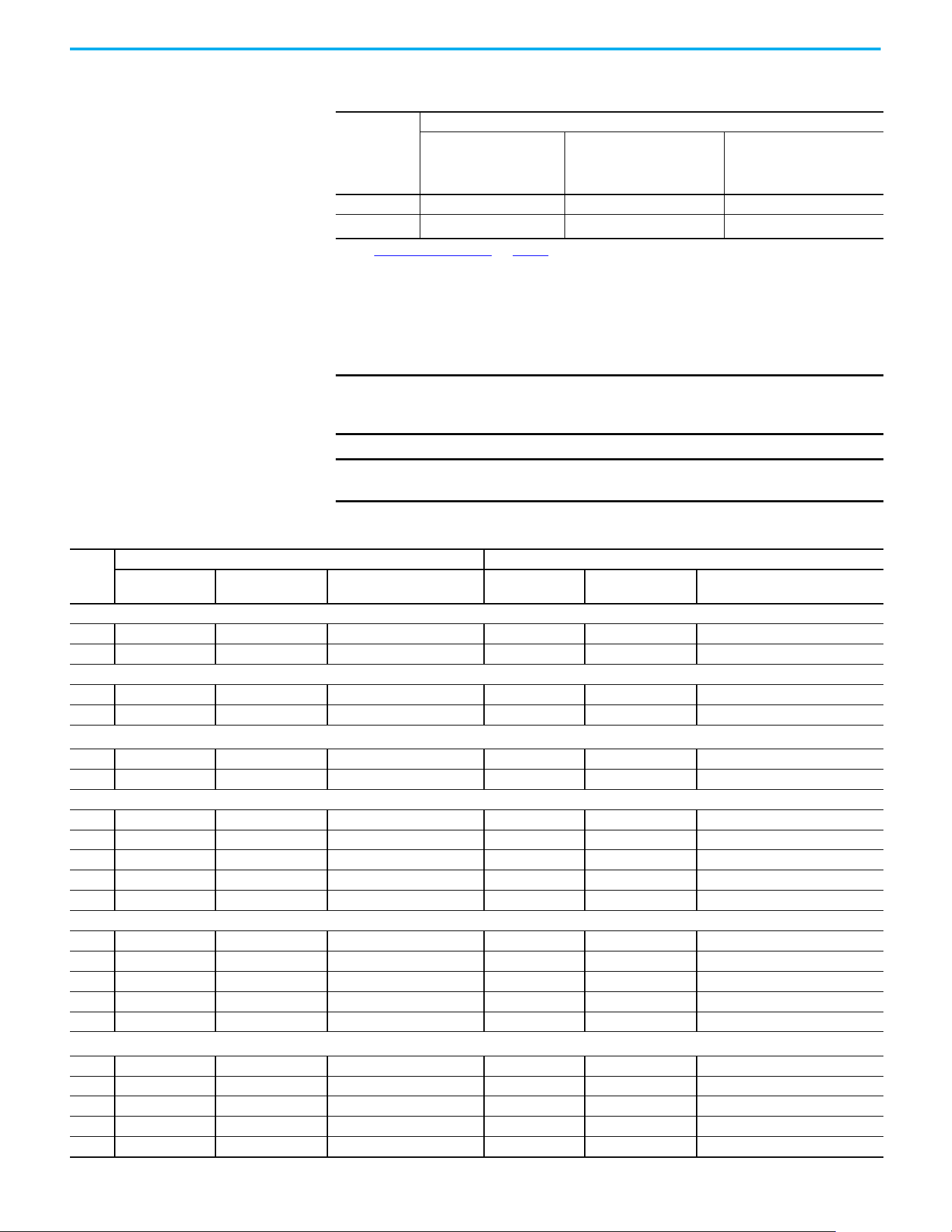
Chapter 1 Installation/Wiring
56 Rockwell Automation Publication 520-UM001N-EN-E - July 2024
Additional Installation Requirements
This section provides information on additional requirements for category C1
and C2 installation, such as enclosures and EMC cores.
PowerFlex 520-series RF Emission Compliance and Installation Requirements
Filter Type
Standard/Limits
EN61800-3 Category C1
EN61000-6-3
CISPR11 Group 1 Class B
EN61800-3 Category C2
EN61000-6-4
CISPR11 Group 1 Class A
(Input power ≤ 20 kVA)
EN61800-3 Category C3
(I ≤ 100 A)
CISPR11 Group 1 Class A
(Input power > 20 kVA)
Internal — 10 m (33 ft) 20 m (66 ft)
External
(1)
(1) See EMC Line Filters on page 177 and page 197 for more information on optional external filters.
30 m (16 ft) 150 m (492 ft) 150 m (492 ft)
IMPORTANT EMC cores are included with:
• Drives that have an internal EMC filter (25x-xxxxN114)
• External EMC filter accessory kit (25-RFxxx)
IMPORTANT An enclosure, shielded input cable, and EMC cores are not required to
meet category C3 requirements.
Additional Installation Requirements
Frame
Size
Category C1 Category C2
Enclosure
(1)
Conduit or Shielded
Cable @ Input
EMC Cores Required
(Included with product)
Enclosure
(1)
Conduit or Shielded
Cable @ Input
EMC Cores Required
(Included with product)
100…120V AC (-15%, +10%) – 1-phase Input with External EMC Filter, 0…120V 1-phase Output
ANoNo No NoNo No
BNoNo No NoNo No
200…240V AC (-15%, +10%) – 1-phase Input with External EMC Filter, 0…230V 3-phase Output
A Yes Yes No No No Input/Output
B Yes Yes Output only No No Input/Output
200…240V AC (-15%, +10%) – 1-phase Input with Internal EMC Filter, 0…230V 3-phase Output
(2)
A* * * Yes No No
B* * * Yes No No
200…240V AC (-15%, +10%) – 3-phase Input with External EMC Filter, 0…230V 3-phase Output
A Yes Yes Output only No No Input/Output
B Yes Yes Output only No No Input/Output
C Yes Yes Output only No No Input/Output
DYes Yes No No No Input only
E Yes Yes Output only No No Input only
380…480V AC (-15%, +10%) – 3-phase Input with External EMC Filter, 0…460V 3-phase Output
A Yes Yes No No No Input/Output
B Yes Yes No No No Input/Output
CYes Yes No No No Input only
D Yes Yes Output only No No Input/Output
E Yes Yes No Yes No Input/Output
380…480V AC (-15%, +10%) – 3-phase Input with Internal EMC Filter, 0…460V 3-phase Output
(2)
A * * * No No Input/Output
B * * * No No Input/Output
C * * * No No Input/Output
D * * * No No Input/Output
E * * * No No Input/Output
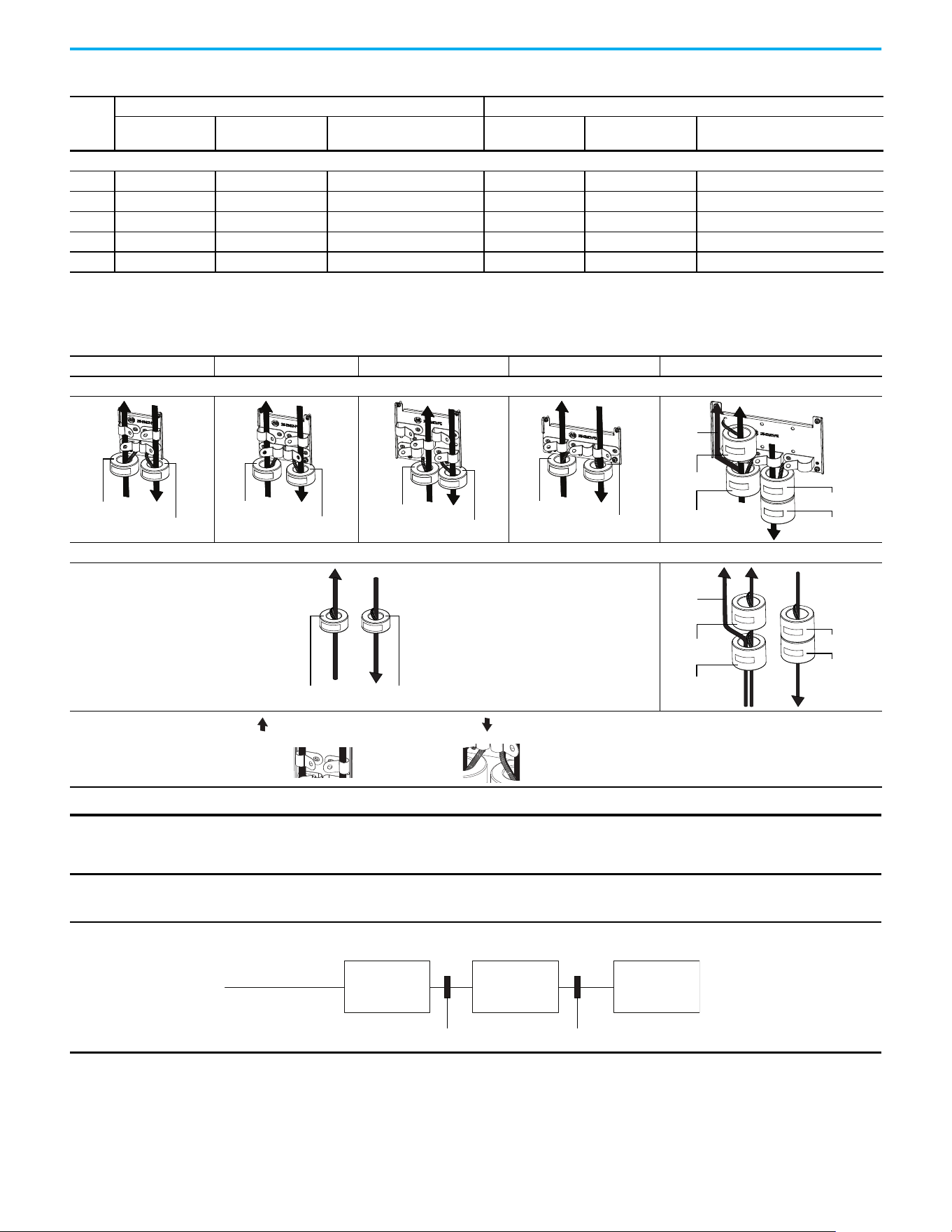
Chapter 1 Installation/Wiring
Rockwell Automation Publication 520-UM001N-EN-E - July 2024 57
525…600V AC (-15%, +10%) – 3-phase Input with External EMC Filter, 0…575V 3-phase Output
A Yes Yes No No No Input/Output
B Yes Yes No No No Input/Output
C Yes Yes No No No Input/Output
D Yes Yes No No No Input/Output
E Yes Yes No Yes No No
(1) Minimum EMC enclosure dimension are 60 x 55 x 80 cm (23.6 x 21.7 x 31.5 in) with a shielding attenuation of at least 92 dB.
(2) An (*) indicates that EMC requirements are not met.
Additional Installation Requirements (Continued)
Frame
Size
Category C1 Category C2
Enclosure
(1)
Conduit or Shielded
Cable @ Input
EMC Cores Required
(Included with product)
Enclosure
(1)
Conduit or Shielded
Cable @ Input
EMC Cores Required
(Included with product)
Recommended Placement of EMC Cores
Frame A Frame B Frame C Frame D Frame E
With optional EMC plate (25-EMC-Fx)
Without EMC plate
CORE-xx-A-1
CORE-xx-A-2
CORE-xx-B-1
CORE-xx-B-2
CORE-xx-C-1
CORE-xx-C-2
CORE-xx-D-1
CORE-xx-D-2
CORE-E-1
CORE-E-2
CORE-E-3
CORE-E-4
Ground
cable
CORE-xx-x-1 CORE-xx-x-2
CORE-E-1
CORE-E-2
CORE-E-3
CORE-E-4
Ground
cable
Shows contact to
shielded layer
Secure EMC core by
using cable/zip ties
Output cable from drive (Shielded)
Input cable to drive (Shielded or Unshielded)
IMPORTANT The ground cable/shield for both input and output must pass through the EMC cores, except for the following:
• Frame E drives with internal filters where the grounded input cable must not pass through EMC CORE-E-1.
• 600V drives with external filters where the grounded output cable must not pass through the EMC cores.
Recommended Placement of EMC Cores Relative to External Filter
Input core Output core
Incoming power
EMC filter Drive Motor
All frame sizes

Chapter 1 Installation/Wiring
58 Rockwell Automation Publication 520-UM001N-EN-E - July 2024
Notes:

Rockwell Automation Publication 520-UM001N-EN-E - July 2024 59
Chapter 2
Startup
This chapter describes how to startup the PowerFlex 520-series drive. To
simplify drive setup, the most commonly programmed parameters are
organized in a single Basic Program Group.
Prepare for Drive Startup Drive Startup Task List
1. Disconnect and lock out power to the machine.
2. Verify that AC line power at the disconnect device is within the rated
value of the drive.
3. If replacing a drive, verify the current drive’s catalog number. Verify all
options installed on the drive.
4. Verify that any digital control power is 24 volts.
5. Inspect grounding, wiring, connections, and environmental
compatibility.
6. Verify that the Sink (SNK)/Source (SRC) jumper is set to match your
control wiring scheme. See the PowerFlex 523 Control I/O Terminal
Block on page 38 and PowerFlex 525 Control I/O Terminal Block on
page 42 for location.
7. Wire I/O as required for the application.
8. Wire the power input and output terminals.
9. Confirm that all inputs are connected to the correct terminals and are
secure.
10. Collect and record motor nameplate and encoder or feedback device
information. Verify motor connections.
• Is the motor uncoupled?
• What direction will the motor need to turn for the application?
IMPORTANT
Read the General Precautions on page 13 section before proceeding.
ATTENTION: Power must be applied to the drive to perform the following
startup procedures. Some of the voltages present are at incoming line
potential. To avoid electric shock hazard or damage to equipment, only
qualified service personnel should perform the following procedure.
Thoroughly read and understand the procedure before beginning. If an
event does not occur while performing this procedure, Do Not Proceed.
Remove All Power including user supplied control voltages. User supplied
voltages may exist even when main AC power is not applied to the drive.
Correct the malfunction before continuing.
IMPORTANT
The default control scheme is Source (SRC). The Stop terminal is
jumpered to allow starting from the keypad or comms. If the control
scheme is changed to Sink (SNK), the jumper must be removed from I/O
Terminals 01 and 11 and installed between I/O Terminals 01 and 04.

60 Rockwell Automation Publication 520-UM001N-EN-E - July 2024
Chapter 2 Startup
11. Verify the input voltage to the drive. Verify if the drive is on a grounded
system. Ensure the MOV jumpers are in the correct position. See AC
Supply Source Considerations on page 19 for more information.
12. Apply power and reset the drive and communication adapters to factory
default settings. To reset the drive, see parameter P053
[Reset to
Defaults]. To reset the communication adapters, see the user manual of
the adapter for more information.
13. Configure the basic program parameters that are related to the motor.
See Smart Startup with Basic Program Group Parameters on page 65
.
14. Complete the autotune procedure for the drive. See parameter P040
[Autotune] for more information.
15. If you are replacing a drive and have a backup of the parameter settings
obtained using the USB utility application, use the USB utility
application to apply the backup to the new drive. See Using the USB Port
on page 67 for more information.
Otherwise, set the necessary parameters for your application using the
LCD keypad interface, Connected Components Workbench™ software,
or RSLogix™, or Studio 5000 Logix Designer application if using an
Add-on Profile through EtherNet/IP.
• Configure the communication parameters needed for the application
(node number, IP address, Datalinks in and out, communication rate,
speed reference, start source, and so on). Record these settings for
your reference.
• Configure the other drive parameters that are needed for the drive
analog and digital I/O to work correctly. Verify the operation. Record
these settings for your reference.
16. Verify that the drive and motor perform as specified.
• Verify that the Stop input is present or the drive does not start.
• Verify that the drive is receiving the speed reference from the correct
place and that the reference is scaled correctly.
• Verify that the drive is receiving start and stop commands correctly.
• Verify that input currents are balanced.
• Verify that motor currents are balanced.
17. Save a backup of the drive settings using the USB utility application. See
Using the USB Port on page 67
for more information.
Start, Stop, Direction, and Speed Control
Factory default parameter values allow the drive to be controlled from the
keypad. No programming is required to start, stop, change direction and
control speed directly from the keypad.
If a fault appears on power-up, see Fault Descriptions on page 161
for an
explanation of the fault code.
IMPORTANT
If I/O Terminal 01 is used as a stop input, the jumper between I/O
Terminals 01 and 11 must be removed.
IMPORTANT
To disable reverse operation, see A544 [Reverse Disable].
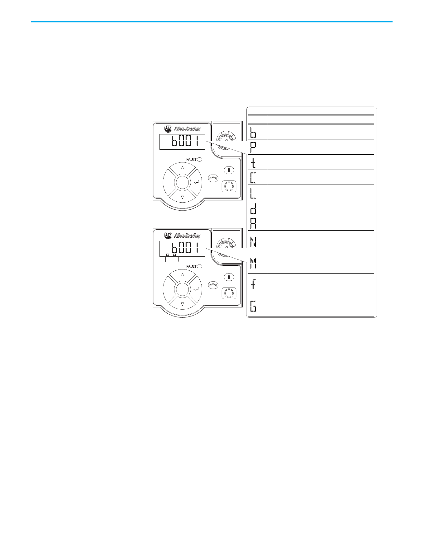
Rockwell Automation Publication 520-UM001N-EN-E - July 2024 61
Chapter 2 Startup
Variable Torque Fan/Pump Applications
For improved motor and drive performance, tune the motor in SVC mode
using parameter P040 [Autotune]. If V/Hz mode is selected, use parameter
A530 [Boost Select] to adjust the boost.
Display and Control Keys
Esc
Sel
F
W
D
Esc
Sel
F
W
D
ENET LINK
EtherNet/IP
Menu Parameter Group and Description
Basic Display
Commonly viewed drive operating conditions.
Basic Program
Commonly used programmable functions.
Terminal Blocks
Programmable terminal functions.
Communications
Programmable communication functions.
Logic (PowerFlex 525 only)
Programmable logic functions.
Advanced Display
Advanced drive operating conditions.
Advanced Program
Remaining programmable functions.
Network
Network functions that are shown only when a
comm card is used.
Modified
Functions from the other groups with values
changed from default.
Fault and Diagnostic
Consists of list of codes for specific fault
conditions.
AppView and CustomView
Functions from the other groups organized for
specific applications.
PowerFlex 523
PowerFlex 525
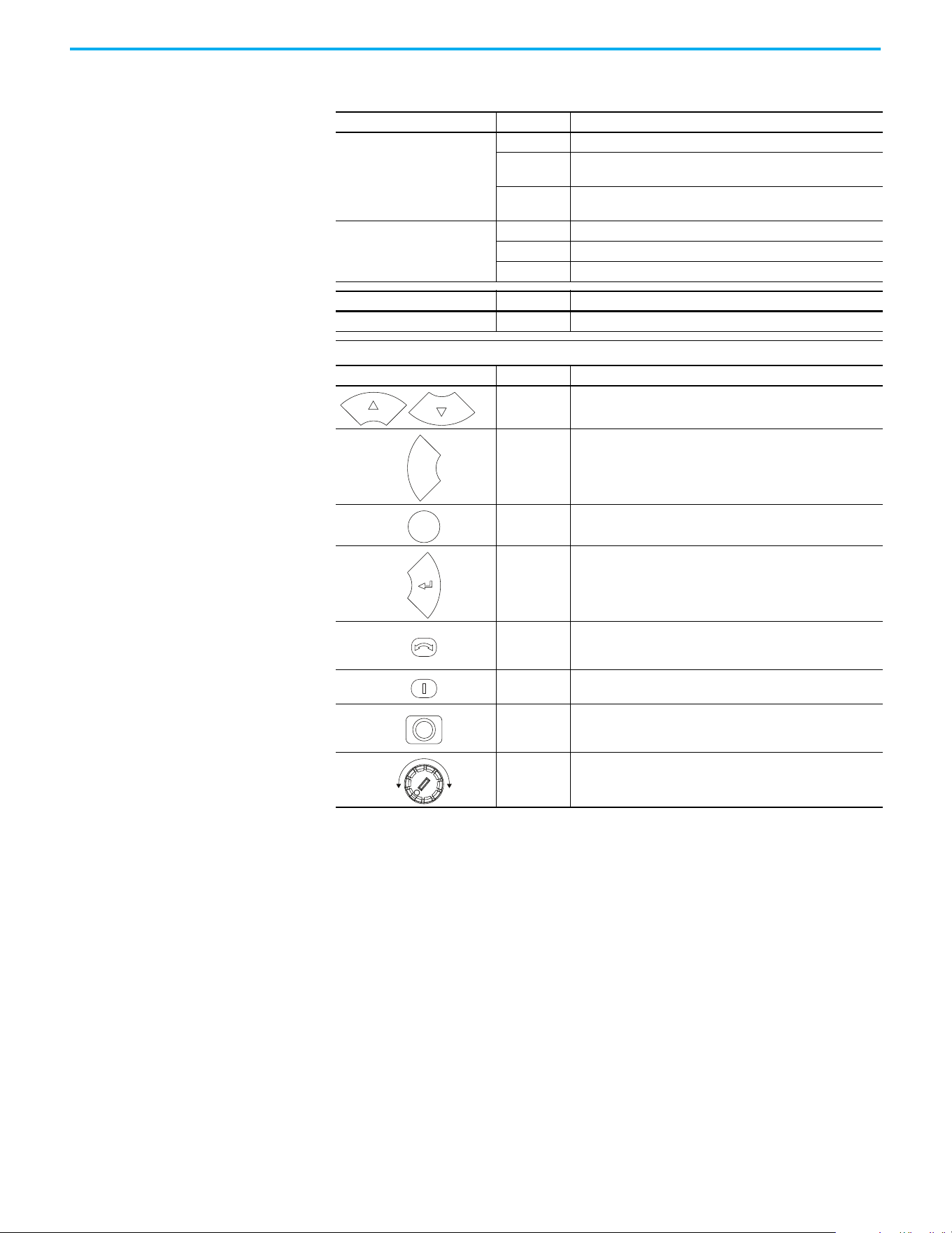
62 Rockwell Automation Publication 520-UM001N-EN-E - July 2024
Chapter 2 Startup
Control and Navigation Keys
Display Display State Description
ENET (PowerFlex 525 only)
Off Adapter is not connected to the network.
Steady
Adapter is connected to the network and drive is controlled
through Ethernet.
Flashing
Adapter is connected to the network but drive is not controlled
through Ethernet.
LINK (PowerFlex 525 only)
Off Adapter is not connected to the network.
Steady Adapter is connected to the network but not transmitting data.
Flashing Adapter is connected to the network and transmitting data.
LED LED State Description
FAULT Flashing Red Indicates that drive is faulted.
Key Name Description
Up Arrow
Down Arrow
Scroll through user-selectable display parameters or groups.
Increment values.
Escape
Back one step in programming menu.
Cancel a change to a parameter value and exit Program Mode.
Select
Advance one step in programming menu.
Select a digit when viewing parameter value.
Enter
Advance one step in programming menu.
Save a change to a parameter value.
Reverse
Used to reverse direction of the drive. Default is active.
Controlled by parameters P046, P048, and P050 [Start Source x]
and A544 [Reverse Disable].
Start
Used to start the drive. Default is active.
Controlled by parameters P046, P048, and P050 [Start Source x].
Stop
Used to stop the drive or clear a fault.
This key is always active.
Controlled by parameter P045 [Stop Mode].
Potentiometer
Used to control speed of drive. Default is active.
Controlled by parameters P047, P049, and P051
[Speed Referencex].
Esc
Sel
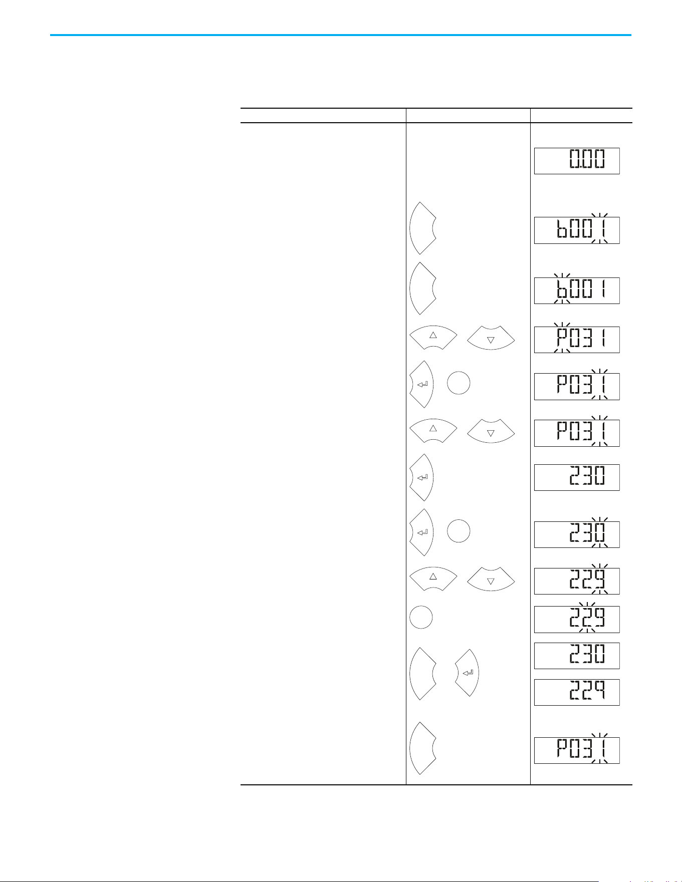
Rockwell Automation Publication 520-UM001N-EN-E - July 2024 63
Chapter 2 Startup
Viewing and Editing
Parameters
The following is an example of basic integral keypad and display functions.
This example provides basic navigation instructions and illustrates how to
program a parameter.
Step Key Example Display
1.
When power is applied, the last user-
selected Basic Display Group parameter
number is briefly displayed with flashing
characters. The display then defaults to
that parameter’s current value. (Example
shows the value of b001 [Output Freq] with
the drive stopped.)
2.
Press Esc to display the Basic Display
Group parameter number shown on power-
up. The parameter number flashes.
3.
Press Esc to enter the parameter group
list. The parameter group letter flashes.
4.
Press the Up Arrow or Down Arrow to scroll
through the group list (b, P, t, C, L, d, A, f
and Gx).
5.
Press Enter or Sel to enter a group. The
right digit of the last viewed parameter in
that group flashes.
6.
Press the Up Arrow or Down Arrow to scroll
through the parameter list.
7.
Press Enter to view the value of the
parameter.
Or
Press Esc to return to the parameter list.
8.
Press Enter or Sel to enter Program Mode
and edit the value. The right digit flashes
and the word Program on the LCD display
lights up.
9.
Press the Up Arrow or Down Arrow to
change the parameter value.
10.
If desired, press Sel to move from digit to
digit or bit to bit. The digit or bit that you
can change flashes.
11.
Press Esc to cancel a change and exit
Program Mode.
Or
Press Enter to save a change and exit
Program Mode.
The digit stops flashing and the word
Program on the LCD display turns off.
12.
Press Esc to return to the parameter list.
Continue to press Esc to back out of the
programming menu.
If pressing Esc does not change the
display, then b001 [Output Freq] is
displayed. Press Enter or Sel to enter the
group list again.
H
ER
T
Z
F
W
D
Esc
F
W
D
Esc
F
W
D
or
F
W
D
Sel
or
F
W
D
or
F
W
D
VOL T S
F
W
D
Sel
or
PROGR
A
M
VOL T S
F
W
D
or
PROGR
A
M
VOL T S
F
W
D
Sel
PROGR
A
M
VOL T S
F
W
D
Esc
or
VOL T S
F
W
D
VOL T S
F
W
D
or
Esc
F
W
D

64 Rockwell Automation Publication 520-UM001N-EN-E - July 2024
Chapter 2 Startup
Drive Programming Tools Some features in the PowerFlex 520-series drive are not supported by older
configuration software tools. It is recommended that customers using such
tools migrate to RSLogix 5000 software (version 17.0 or later) or Studio 5000
Logix Designer application (version 21.0 or later) with AOP, or Connected
Components Workbench software version 5.0 or later to enjoy a richer, full-
featured configuration experience. For Automatic Device Configuration (ADC)
support, RSLogix 5000 software version 20.0 or later is required.
Language Support
Description Catalog Number/Release Version
Connected Components Workbench
(1)
software
(1) Available to download at rok.auto/ccw.
Version 5.0 or later
Logix Designer application Version 21.0 or later
RSLogix 5000 software Version 17.0 or later
Built-in USB software tool —
Serial Converter Module
(2)
(2) Does not support the new dynamic parameter groups (AppView®, CustomView™), and CopyCat functionality is limited to the
linear parameter list.
22-SCM-232
USB Converter Module
(2)
1203-USB
Remote Panel Mount, LCD Display
(2)
22-HIM-C2S
Remote Handheld, LCD Display
(2)
22-HIM-A3
Language Keypad/LCD Display
RSLogix 5000/
Logix Designer
Application
Connected Components
Workbench Software
English Y Y Y
French Y Y Y
Spanish Y Y Y
Italian Y Y Y
German Y Y Y
Japanese — Y —
Portuguese Y Y —
Chinese Simplified — Y Y
Korean — Y —
Polish
(1)
(1) Due to a limitation of the LCD Display, some of the characters for Polish, Turkish, and Czech will be modified.
Y— —
Turkish
(1)
Y— —
Czech
(1)
Y— —
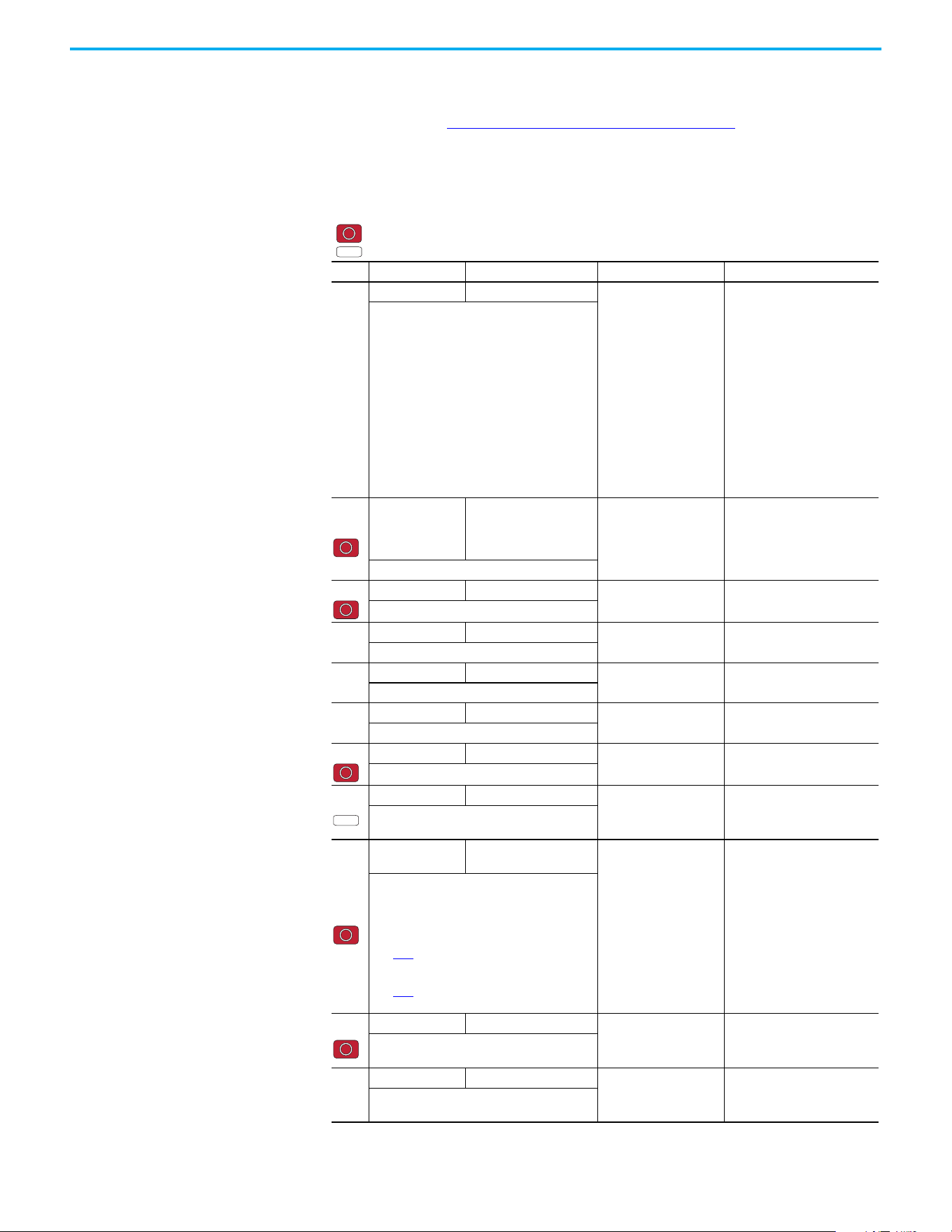
Rockwell Automation Publication 520-UM001N-EN-E - July 2024 65
Chapter 2 Startup
Smart Startup with Basic
Program Group Parameters
The PowerFlex 520-series drive is designed so that startup is simple and
efficient. The Basic Program Group contains the most commonly used
parameters. See Programming and Parameters on page 71
for detailed
descriptions of the parameters that are listed here and the full list of available
parameters.
Basic Program Group Parameters
= Stop drive before changing this parameter.
= Parameter is specific to PowerFlex 525 drives only.
No. Parameter Min/Max Display/Options Default
P030
[Language] 1/15 1 = English
2= Français
3= Español
4= Italiano
5= Deutsch
6= Reserved
7= Português
8= Reserved
9= Reserved
10= Reserved
11 = Reserved
12 = Polish
13 = Reserved
14= Turkish
15 = Czech
1
Selects the language displayed.
Important: The setting takes effect after the
drive is power cycled.
P031
[Motor NP Volts]
10V (for 200V Drives), 20V
(for 400V Drives), 25V (for
600V Drives)/Drive Rated
Volts
1V Based on Drive Rating
Sets the motor nameplate rated volts.
P032 [Motor NP Hertz] 15/500 Hz
1 Hz 60 Hz
Sets the motor nameplate rated frequency.
P033
[Motor OL Current] 0.0/(Drive Rated Amps x 2)
0.1 A Based on Drive Rating
Sets the motor nameplate overload current.
P034
[Motor NP FLA] 0.0/(Drive Rated Amps x 2)
0.1 A Drive Rated Amps
Sets the motor nameplate FLA.
P035
[Motor NP Poles] 2/40
14
Sets the number of poles in the motor.
P036 [Motor NP RPM] 0/24000 rpm
1 rpm 1750 rpm
Sets the rated nameplate rpm of motor.
P037
[Motor NP Power] 0.00/Drive Rated Power
0.01 kW Drive Rated Power
Sets the motor nameplate power. Used in PM
regulator.
P039
[Torque Perf
Mode]
0/4
0 = “V/Hz”
1 = “SVC”
2 = “Economize”
3 = “Vector”
(1)
4 = “PM Control”
(1)(2)(3)
5 = “SynRM”
1
Selects the motor control mode.
(1) Setting is specific to PowerFlex 525 drives only.
(2) Setting is available in PowerFlex 525 FRN 5.xxx
and later.
(3) When P039 [Torque Perf Mode] is set to 4 and
A535
[Motor Fdbk Type] is set to 0, 1, 2 or 3, the
drive is in open loop PM motor control mode.
When P039 [Torque Perf Mode] is set to 4 and
A535
[Motor Fdbk Type] is set to 4 or 5, the
drive is in closed loop PM motor control mode.
P040
[Autotune] 0/2
0 = “Ready/Idle”
1 = “Static Tune”
2 = “Rotate Tune”
0
Enables a static (not spinning) or dynamic
(motor spinning) autotune.
P041
[Accel Time 1] 0.00/600.00 s
0.01 s 10.00 s
Sets the time for the drive to accel from 0 Hz
to [Maximum Freq].
PF 525
PF 525
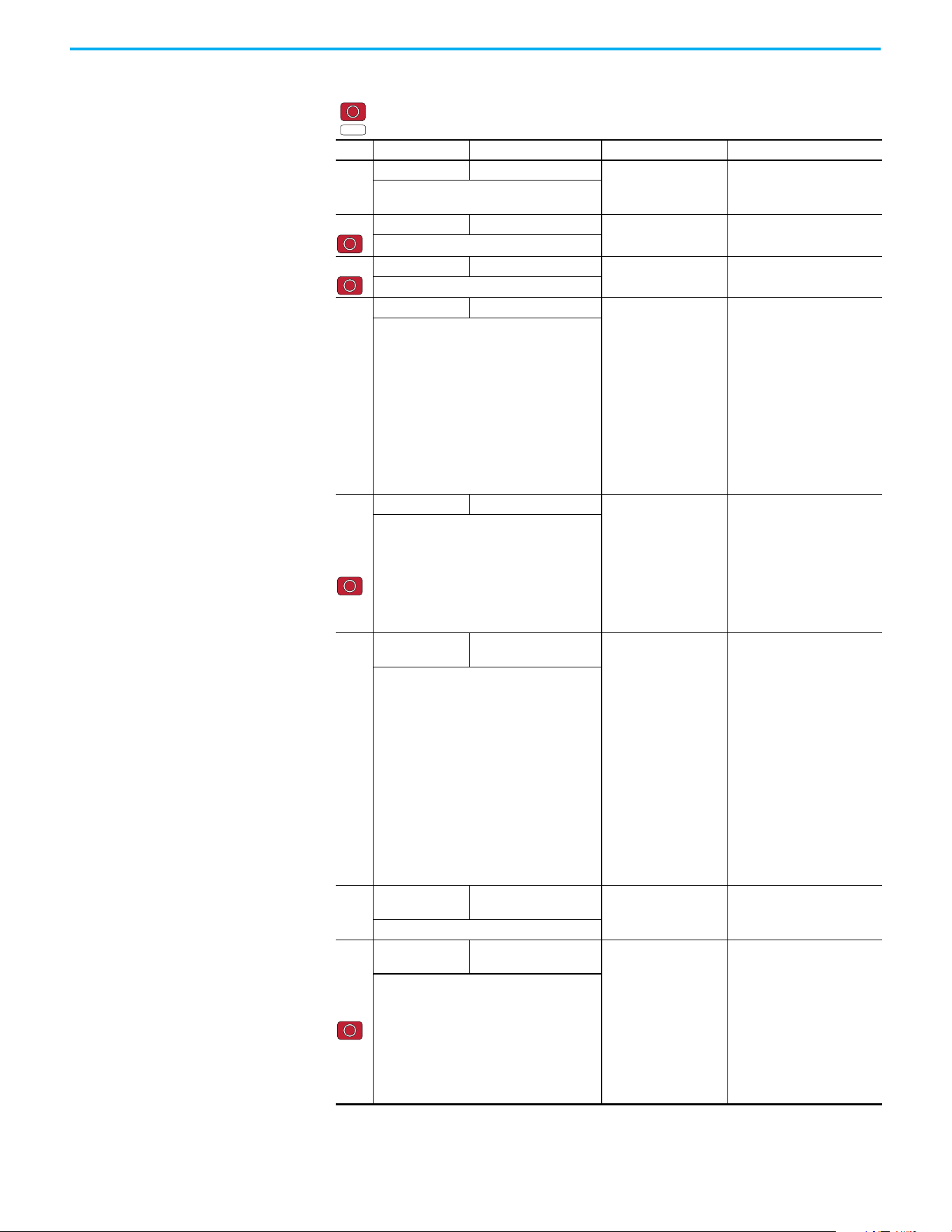
66 Rockwell Automation Publication 520-UM001N-EN-E - July 2024
Chapter 2 Startup
P042
[Decel Time 1] 0.00/600.00 s
0.01 s 10.00 s
Sets the time for the drive to decel from
[Maximum Freq] to 0 Hz.
P043 [Minimum Freq] 0.00/500.00 Hz
0.01 Hz 0.00 Hz
Sets the lowest frequency the drive outputs.
P044 [Maximum Freq] 0.00/500.00 Hz
0.01 Hz 60.00 Hz
Sets the highest frequency the drive outputs.
P045
[Stop Mode] 0/11
0= “Ramp, CF”
(1)
1= “Coast, CF”
(1)
2= “DC Brake, CF”
(1)
3= “DCBrkAuto,CF”
(1)
4= “Ramp”
5= “Coast”
6= “DC Brake”
7= “DC BrakeAuto”
8= “Ramp+EM B,CF”
(1)
9= “Ramp+EM Brk”
10= “PointStp,CF”
(1)
11= “PointStop”
0
Stop command for normal stop.
Important: I/O Terminal 01 is always a stop
input. The stopping mode is determined by the
drive setting.
Important: The drive is shipped with a jumper
that is installed between I/O Terminals 01 and
11. Remove this jumper when using I/O
Terminal 01 as a stop or enable input.
(1) Stop input also clears active fault.
P046,
P048,
P050
[Start Source 1] 1/5
1 = “Keypad”
(1)
2 = “DigIn TrmBlk”
(2)
3 = “Serial/DSI”
4 = “Network Opt”
5 = “EtherNet/IP”
(3)
P046 = 1
P048 = 2
P050 = 3 (PowerFlex 523)
5 (PowerFlex 525)
Sets the default control scheme that is used to
start the drive unless overridden by P048
[Start Source 2] or P050 [Start Source 3].
(1) When active, the Reverse key is also active
unless disabled by A544 [Reverse Disable].
(2) If “DigIn TrmBlk” is selected, ensure that the
digital inputs are properly configured.
(3) Setting is specific to PowerFlex 525 drives only.
P047,
P049,
P051
[Speed
Reference1]
1/16
1= “Drive Pot”
2= “Keypad Freq”
3= “Serial/DSI”
4= “Network Opt”
5= “0-10V Input”
6= “4-20mA Input”
7= “Preset Freq”
8= “Anlg In Mult”
(1)
9= “MOP”
10= “Pulse Input”
11= “PID1 Output”
12= “PID2 Output”
(1)
13= “Step Logic”
(1)
14= “Encoder”
(1)
15= “EtherNet/IP”
(1)
16= “Positioning”
(1)
P047 = 1
P049 = 5
P051 = 3 (PowerFlex 523)
15 (PowerFlex 525)
Sets the default speed command of the drive
unless overridden by P049 [Speed Reference2]
or P051 [Speed Reference3].
(1) Setting is specific to PowerFlex 525 drives only.
P052
[Average kWh
Cost]
0.00/655.35
0.01 0.00
Sets the average cost per kWh.
P053
[Reset To
Defaults]
0/4
0 = “Ready/Idle”
1 = “Param Reset”
2 = “Factory Rset”
3 = “Power Reset”
4 = “Module Reset”
(1)(2)(3)
0
Resets parameters to their factory defaults
values. After a Reset command, the value of
this parameter returns to zero.
(1) Power cycle of the drive, NO parameters are
reset.
(2) Setting is available in PowerFlex 525 FRN 5.xxx
and later.
(3) Setting is available in PowerFlex 523 FRN 3.xxx
and later.
Basic Program Group Parameters (Continued)
= Stop drive before changing this parameter.
= Parameter is specific to PowerFlex 525 drives only.
No. Parameter Min/Max Display/Options Default
PF 525
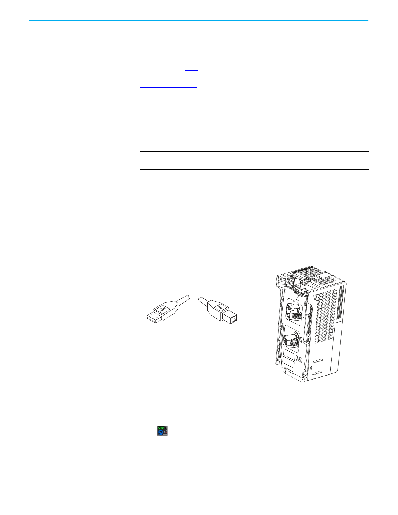
Rockwell Automation Publication 520-UM001N-EN-E - July 2024 67
Chapter 2 Startup
LCD Display with QuickView
Technology
QuickView® technology enables text to scroll across the LCD display of the
PowerFlex 520-series drive. This allows you to easily configure parameters,
troubleshoot faults, and view diagnostic items without using a separate device.
Use parameter A556
[Text Scroll] to set the speed at which the text scrolls
across the display. Select 0 “Off” to turn off text scrolling. See Language
Support on page 64 for the languages supported by the PowerFlex 520-series
drive.
Using the USB Port The PowerFlex 520-series drive has a USB port that connects to a PC for
upgrading drive firmware or uploading/downloading a parameter
configuration.
MainsFree Programming
The MainsFree™ programming feature allows you to quickly configure your
PowerFlex 520-series drive without having to power up the control module or
install additional software. Simply connect the control module to your PC with
a USB Type B cable and you can download a parameter configuration to your
drive. You can also easily upgrade your drive with the latest firmware.
Connecting a PowerFlex 520-series drive to a PC
When connected, the drive appears on the PC and contains two files:
• GUIDE.PDF
This file contains links to relevant product documentation and software
downloads.
• PF52XUSB.EXE
This file is an application to flash upgrade firmware or upload/download
a parameter configuration.
It is not possible to delete these files or add more to the drive.
IMPORTANT
PowerFlex 525 with firmware revision 7.001 and later supports the USB
application with Microsoft Windows® 8 and 10.
USB port
Control Module
USB Type B cable
Connect to Control ModuleConnect to PC
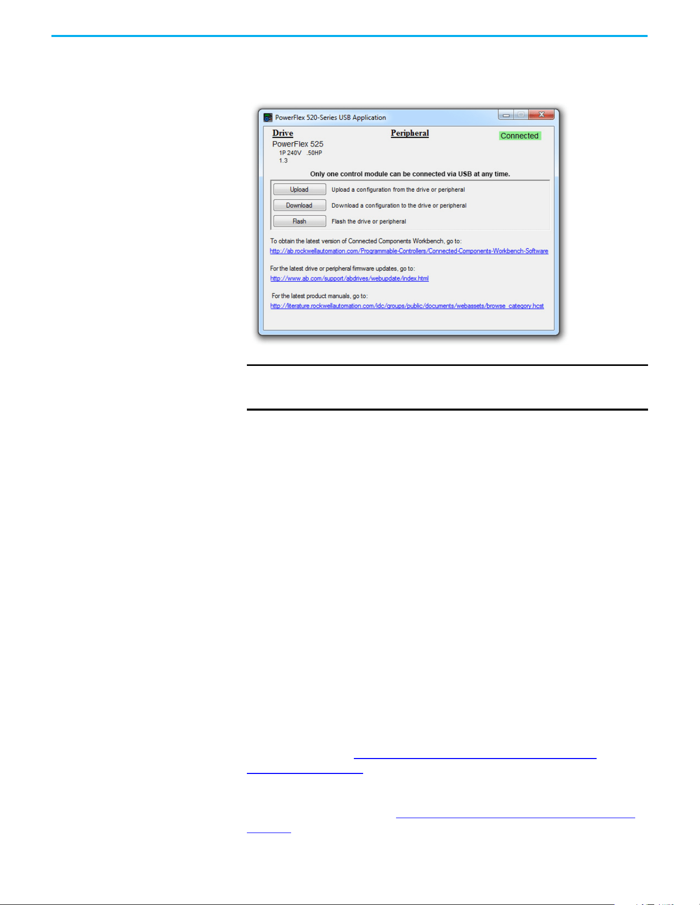
68 Rockwell Automation Publication 520-UM001N-EN-E - July 2024
Chapter 2 Startup
Double-click the PF52XUSB.EXE file to launch the USB utility application. The
main menu is displayed. Follow the program instructions to upgrade the
firmware or upload/download configuration data.
Limitation in Downloading .pf5 Configuration Files with the USB Utility Application
Before downloading a .pf5 configuration file using the USB utility application,
parameter C169 [MultiDrv Sel] in the destination drive must match the
incoming configuration file. If it does not, set the parameter manually to
match and then cycle drive power. Also, the drive type of the .pf5 file must
match the drive.
This means you cannot apply a multi-drive configuration using the USB utility
application to a drive in single mode (parameter C169 [MultiDrv Sel] set to 0
“Disabled”), or apply a single mode configuration to a drive in multi-drive
mode.
Using Drive Startup in CCW
or Logix Designer
Application
To use the PowerFlex 525 Startup Wizard in Connected Components
Workbench software to automatically configure the parameters, make sure
you have installed the following:
• PowerFlex 525 drive firmware revision 5.001 or later.
• PowerFlex 525 drive Add-on Profile version 5.07 or later.
• Latest drive database for Connected Components Workbench software.
For instructions, see Using Drive Startup in CCW or Logix Designer
Application on page 68.
Alternatively, you can manually configure the parameters by using the drive
keypad. For instructions, see Manual Configuration Using Drive Keypad on
page 258.
IMPORTANT
Make sure that your PC is powered by an AC power outlet or has a fully
charged battery before starting any operation. This prevents the
operation from terminating before completion due to insufficient power.
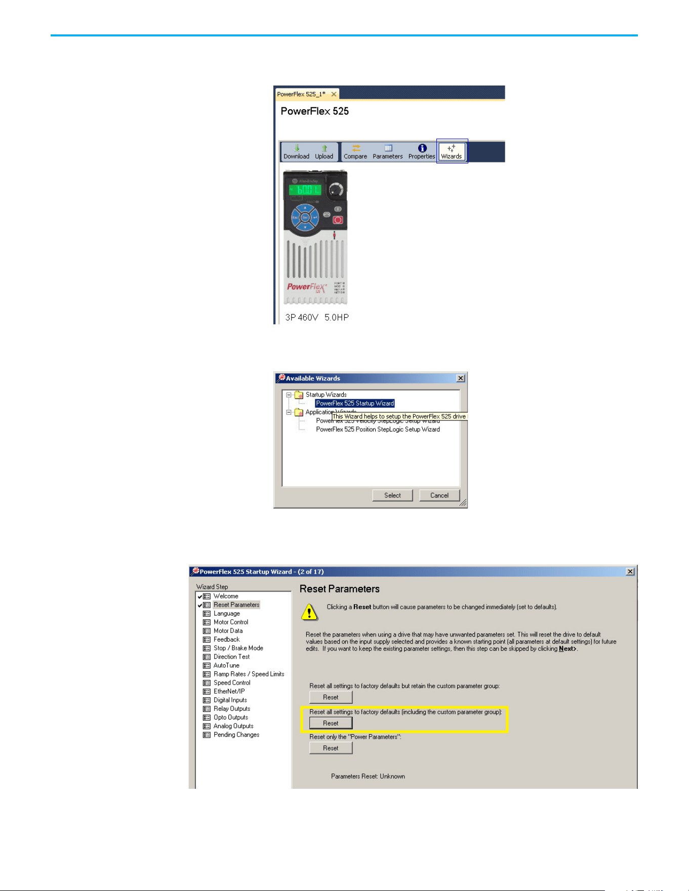
Rockwell Automation Publication 520-UM001N-EN-E - July 2024 69
Chapter 2 Startup
1. From Connected Components Workbench software, click the Wizard
Browser icon.
2. In the Available Wizards dialog box, click PowerFlex 525 Startup Wizard,
then click Select.
3. Before tuning the drive, it is recommended to reset all parameters to
their default values. Select the option shown below.

70 Rockwell Automation Publication 520-UM001N-EN-E - July 2024
Chapter 2 Startup
4. Complete each step in the Startup Wizard to configure the drive.
IMPORTANT
Follow the Startup Wizard steps exactly. If not, unexpected
results can occur.

Rockwell Automation Publication 520-UM001N-EN-E - July 2024 71
Chapter 3
Programming and Parameters
This chapter provides a complete listing and description of the PowerFlex 520-
series drive parameters. Parameters are programmed (viewed/edited) using
either the drive’s built-in keypad, RSLogix 5000 software version 17.0 or later,
Studio 5000 Logix Designer application version 21.0 or later, or Connected
Components Workbench software version 5.0 or later. The Connected
Components Workbench software can be used offline (through USB) to upload
parameter configurations to the drive or online (through Ethernet
connection).
Limited functionality is also available when using the Connected Components
Workbench software online (through DSI and serial converter module), a
legacy external HIM, or legacy software online (DriveTools™ SP). When using
these methods, the parameter list can only be displayed linearly, and there is
no access to communications option card programming.
About Parameters To configure a drive to operate in a specific way, drive parameters may have to
be set. Three types of parameters exist:
• ENUM
ENUM parameters allow a selection from two or more items. Each item
is represented by a number.
• Numeric Parameters
These parameters have a single numerical value (0.1V).
• Bit Parameters
Bit parameters have five individual digits that are associated with
features or conditions. If the digit is 0, the feature is off or the condition
is false. If the digit is 1, the feature is on or the condition is true.
Some parameters are marked as follows.
32-bit Parameters
Parameters marked 32-bit will have two parameter numbers when using RS-
485 communications and programming software. For example, parameters
b010 [Process Display] and b011 [Process Fract] are scaled and displayed as
follows.
• P043 [Minimum Freq] = 0 Hz
= Stop drive before changing this parameter.
= 32-bit parameter
= Parameter is specific to PowerFlex 525 drives only.
32
PF 525
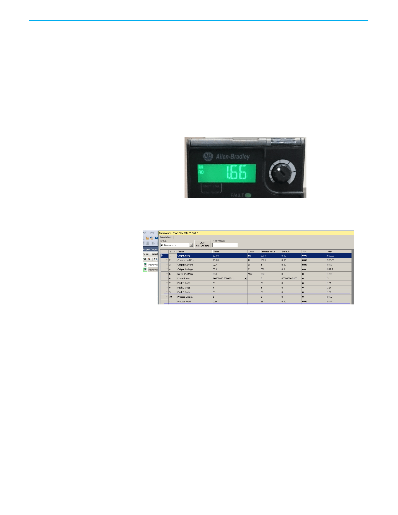
72 Rockwell Automation Publication 520-UM001N-EN-E - July 2024
Chapter 3 Programming and Parameters
• P044 [Maximum Freq] = 60 Hz
• A481 [Process Display Lo] = 0
• A482 [Process Display Hi] = 10
Using the formula
when the drive is running at 10 Hz, the Process Value is 1.66.
On the drive LCD display, only parameter b010 [Process Display] is shown.
In Connected Components Workbench software, parameter b010 [Process
Display] and b011 [Process Fract] are shown separately.
Scaled Process Value (PV) =
([Process Disp Hi] - [Process Disp Lo]) x ([Output Freq] - [Minimum Freqp])
[Maximum Freq] - [Minimum Freq]

Rockwell Automation Publication 520-UM001N-EN-E - July 2024 73
Chapter 3 Programming and Parameters
Parameter Groups For an alphabetical listing of parameters, see Parameter Cross-reference by
Name on page 154.
Parameters List
Basic Display
Output Freq b001
Commanded Freq b002
Output Current b003
Output Voltage b004
DC Bus Voltage b005
Drive Status b006
Fault 1 Code b007
Fault 2 Code b008
Fault 3 Code b009
Process Display b010
Process Fract b011
Control Source b012
Contrl In Status b013
Dig In Status b014
Output RPM b015
Output Speed b016
Output Power b017
Power Saved b018
Elapsed Run Time b019
Average Power b020
Elapsed kWh b021
Elapsed MWh b022
Energy Saved b023
Accum kWh Sav b024
Accum Cost Sav b025
Accum CO2 Sav b026
Drive Temp b027
Control Temp b028
Control SW Ver b029
Basic Program
Language P030
Motor NP Volts P031
Motor NP Hertz P032
Motor OL Current P033
Motor NP FLA P034
Motor NP Poles P035
Motor NP RPM P036
Motor NP Power
(1)
P037
Voltage Class P038
Torque Perf Mode P039
Autotune P040
Accel Time 1 P041
Decel Time 1 P042
Minimum Freq P043
Maximum Freq P044
Stop Mode P045
Start Source 1 P046
Speed Reference1 P047
Start Source 2 P048
Speed Reference2 P049
Start Source 3 P050
Speed Reference3 P051
Average kWh Cost P052
Reset To Defalts P053
Display Param P054
Terminal Blocks
DigIn TermBlk 02 t062
DigIn TermBlk 03 t063
2-Wire Mode t064
DigIn TermBlk 05 t065
DigIn TermBlk 06 t066
DigIn TermBlk 07
(1)
t067
DigIn TermBlk 08
(1)
t068
Opto Out1 Sel
(1)
t069
Opto Out1 Level
(1)
t070
Opto Out1 LevelF t071
Opto Out2 Sel
(1)
t072
Opto Out2 Level
(1)
t073
Opto Out2 LevelF t074
Opto Out Logic
(1)
t075
Relay Out1 Sel t076
Relay Out1 Level t077
Relay Out1 LevelF t078
Relay 1 On Time t079
Relay 1 Off Time t080
Relay Out2 Sel
(1)
t081
Relay Out2 Level
(1)
t082
Relay Out2 LevelF
(1)
t083
Relay 2 On Time
(1)
t084
Relay 2 Off Time
(1)
t085
EM Brk Off Delay t086
EM Brk On Delay t087
Analog Out Sel
(2)
t088
Analog Out High
(2)
t089
Anlg Out Setpt
(2)
t090
Anlg In 0-10V Lo t091
Anlg In 0-10V Hi t092
10V Bipolar Enbl
(1)
t093
Anlg In V Loss t094
Anlg In4-20mA Lo t095
Anlg In4-20mA Hi t096
Anlg In mA Loss t097
Anlg Loss Delay t098
Analog In Filter t099
Sleep-Wake Sel t100
Sleep Level t101
Sleep Time t102
Wake Level t103
Wake Time t104
Safety Open En
(1)
t105
SafetyFlt RstCfg
(1)(3)
t106
Communications
Comm Write Mode C121
Cmd Stat Select
(1)
C122
RS485 Data Rate C123
RS485 Node Addr C124
Comm Loss Action C125
Comm Loss Time C126
RS485 Format C127
EN Addr Sel
(1)
C128
EN IP Addr Cfg 1
(1)
C129
EN IP Addr Cfg 2
(1)
C130
EN IP Addr Cfg 3
(1)
C131
EN IP Addr Cfg 4
(1)
C132
EN Subnet Cfg 1
(1)
C133
EN Subnet Cfg 2
(1)
C134
EN Subnet Cfg 3
(1)
C135
EN Subnet Cfg 4
(1)
C136
EN Gateway Cfg 1
(1)
C137
EN Gateway Cfg 2
(1)
C138
EN Gateway Cfg 3
(1)
C139
EN Gateway Cfg 4
(1)
C140
EN Rate Cfg
(1)
C141
EN Comm Flt Actn
(1)
C143
EN Idle Flt Actn
(1)
C144
EN Flt Cfg Logic
(1)
C145
EN Flt Cfg Ref
(1)
C146
EN Flt Cfg DL 1
(1)
C147
EN Flt Cfg DL 2
(1)
C148
EN Flt Cfg DL 3
(1)
C149
EN Flt Cfg DL 4
(1)
C150
EN Data In 1
(1)
C153
EN Data In 2
(1)
C154
EN Data In 3
(1)
C155
EN Data In 4
(1)
C156
EN Data Out 1
(1)
C157
EN Data Out 2
(1)
C158
EN Data Out 3
(1)
C159
EN Data Out 4
(1)
C160
Opt Data In 1 C161
Opt Data In 2 C162
Opt Data In 3 C163
Opt Data In 4 C164
Opt Data Out 1 C165
Opt Data Out 2 C166
Opt Data Out 3 C167
Opt Data Out 4 C168
MultiDrv Sel C169
Drv 1 Addr C171
Drv 2 Addr C172
Drv 3 Addr C173
Drv 4 Addr C174
DSI I/O Cfg C175
Logic
(1)
Stp Logic 0 L180
Stp Logic 1 L181
Stp Logic 2 L182
Stp Logic 3 L183
Stp Logic 4 L184
Stp Logic 5 L185
Stp Logic 6 L186
Stp Logic 7 L187
Stp Logic Time 0 L190
Stp Logic Time 1 L191
Stp Logic Time 2 L192
Stp Logic Time 3 L193
Stp Logic Time 4 L194
Stp Logic Time 3 L193
Stp Logic Time 4 L194
Stp Logic Time 5 L195
Stp Logic Time 6 L196
Stp Logic Time 7 L197
Step Units 0 L200
Step Units F 0 L201
Step Units 1 L202
Step Units F 1 L203
Step Units 2 L204
Step Units F 2 L205
Step Units 3 L206
Step Units F 3 L207
Step Units 4 L208
Step Units F 4 L209
Step Units 5 L210
Step Units F 5 L211
Step Units 6 L212
Step Units F 6 L213
Step Units 7 L214
Step Units F 7 L215
Advanced Display
Analog In 0-10V d360
Analog In 4-20mA d361
Elapsed Time-hr d362
Elapsed Time-min d363
Counter Status d364
Timer Status d365
Timer StatusF d366
Drive Type d367
Testpoint Data d368
Motor OL Level d369
Slip Hz Meter d375
Speed Feedback d376
Speed Feedback F d377
Encoder Speed
(2)
d378
Encoder Speed F d379
DC Bus Ripple d380
Output Powr Fctr d381
Torque Current d382
PID1 Fdbk Displ d383
PID1 Setpnt Disp d384
PID2 Fdbk Displ
(1)
d385
PID2 Setpnt Disp
(1)
d386
Position Status
(1)
d387
Units Traveled H
(1)
d388
Units Traveled L
(1)
d389
RdyBit Mode Act
(2)(4)
d392
Drive Status 2
(2)(3)
d393
Dig Out Status
(2)(3)
d394
Fiber Status d390
Stp Logic Status
(1)
d391

74 Rockwell Automation Publication 520-UM001N-EN-E - July 2024
Chapter 3 Programming and Parameters
Advanced Program
Preset Freq 0 A410
Preset Freq 1 A411
Preset Freq 2 A412
Preset Freq 3 A413
Preset Freq 4 A414
Preset Freq 5 A415
Preset Freq 6 A416
Preset Freq 7 A417
Preset Freq 8
(1)
A418
Preset Freq 9
(1)
A419
Preset Freq 10
(1)
A420
Preset Freq 11
(1)
A421
Preset Freq 12
(1)
A422
Preset Freq 13
(1)
A423
Preset Freq 14
(1)
A424
Preset Freq 15
(1)
A425
Keypad Freq A426
MOP Freq A427
MOP Reset Sel A428
MOP Preload A429
MOP Time A430
Jog Frequency A431
Jog Accel/Decel A432
Purge Frequency A433
DC Brake Time A434
DC Brake Level A435
DC Brk Time@Strt A436
DB Resistor Sel A437
DB Threshold A438
S Curve % A439
PWM Frequency A440
Droop Hertz@ FLA
(1)
A441
Accel Time 2 A442
Decel Time 2 A443
Accel Time 3 A444
Decel Time 3 A445
Accel Time 4 A446
Decel Time 4 A447
Skip Frequency 1 A448
Skip Freq Band 1 A449
Skip Frequency 2 A450
Skip Freq Band 2 A451
Skip Frequency 3
(1)
A452
Skip Freq Band 3
(1)
A453
Skip Frequency 4
(1)
A454
Skip Freq Band 4
(1)
A455
PID 1 Trim Hi A456
PID 1 Trim Lo A457
PID 1 Trim Sel A458
PID 1 Ref Sel A459
PID 1 Fdback Sel A460
PID 1 Prop Gain A461
PID 1 Integ Time A462
PID 1 Diff Rate A463
PID 1 Setpoint A464
PID 1 Deadband A465
PID 1 Preload A466
PID 1 Invert Err A467
PID 2 Trim Hi
(1)
A468
PID 2 Trim Lo
(1)
A469
PID 2 Trim Sel
(1)
A470
PID 2 Ref Sel
(1)
A471
PID 2 Fdback Sel
(1)
A472
PID 2 Prop Gain
(1)
A473
PID 2 Integ Time
(1)
A474
PID 2 Diff Rate
(1)
A475
PID 2 Setpoint
(1)
A476
PID 2 Deadband
(1)
A477
PID 2 Preload
(1)
A478
PID 2 Invert Err
(1)
A479
Process Disp Lo A481
Process Disp Hi A482
Testpoint Sel A483
Current Limit 1 A484
Current Limit 2
(1)
A485
Shear Pin1 Level A486
Shear Pin 1 Time A487
Shear Pin2 Level
(1)
A488
Shear Pin 2 Time
(1)
A489
Load Loss Level
(1)
A490
Load Loss Time
(1)
A491
Stall Fault Time A492
Motor OL Select A493
Motor OL Ret A494
Drive OL Mode A495
IR Voltage Drop A496
Flux Current Ref A497
Motor Rr
(1)
A498
Motor Lm
(1)
A499
Motor Lx
(1)
A500
PM IR Voltage
(1)(3)
A501
PM IXd Voltage
(1)(3)
A502
PM IXq Voltage
(1)(3)
A503
PM BEMF Voltage
(1)(3)
A504
Speed Reg Sel
(1)
A509
Freq 1
(1)
A510
Freq 1 BW
(1)
A511
Freq 2
(1)
A512
Freq 2 BW
(1)
A513
Freq 3
(1)
A514
Freq 3 BW
(1)
A515
PM Initial Sel
(1)(3)
A516
PM DC Inject Cur
(1)(3)
A517
PM Align Time
(1)(3)
A518
PM HIFI NS Cur
(1)(3)
A519
PM Bus Reg Kd
(1)(3)
A520
Freq 1 Kp
(1)
A521
Freq 1 Ki
(1)
A522
Freq 2 Kp
(1)
A523
Freq 2 Ki
(1)
A524
Freq 3 Kp
(1)
A525
Freq 3 Ki
(1)
A526
PM FWKn 1 Kp
(1)(3)
A527
PM FWKn 2 Kp
(1)(3)
A528
PM Control Cfg
(1)(3)
A529
Boost Select A530
Start Boost A531
Break Voltage A532
Break Frequency A533
Maximum Voltage A534
Motor Fdbk Type
(2)
A535
Encoder PPR
(1)
A536
Pulse In Scale A537
Ki Speed Loop
(2)
A538
Kp Speed Loop
(2)
A539
Var PWM Disable A540
Auto Rstrt Tries A541
Auto Rstrt Delay A542
Start At PowerUp A543
Reverse Disable A544
Flying Start En A545
FlyStrt CurLimit A546
Compensation A547
Power Loss Mode A548
Half Bus Enable A549
Bus Reg Enable A550
Fault Clear A551
Program Lock A552
Program Lock Mod A553
Drv Ambient Sel A554
Reset Meters A555
Text Scroll A556
Out Phas Loss En A557
Positioning Mode
(1)
A558
Counts Per Unit
(1)
A559
Enh Control Word
(1)
A560
Home Save
(1)
A561
Find Home Freq
(1)
A562
Find Home Dir
(1)
A563
Encoder Pos Tol
(1)
A564
Pos Reg Filter
(1)
A565
Pos Reg Gain
(1)
A566
Max Traverse A567
Traverse Inc A568
Traverse Dec A569
P Jump A570
Sync Time A571
Speed Ratio A572
Mtr Options Cfg
(2)(5)
A573
RdyBit Mode Cfg
(2)(4)
A574
Flux Braking En
(2)(3)
A575
Phase Loss Level
(2)(3)
A576
Current Loop BW
(1)(3)
A580
PM Stable 1 Freq
(1)(3)
A581
PM Stable 2 Freq
(1)(3)
A582
PM Stable 1 Kp
(1)(3)
A583
PM Stable 2 Kp
(1)(3)
A584
PM Stable Brk Pt
(1)(3)
A585
PM Stepload Kp
(1)(3)
A586
PM 1 Efficiency
(1)(3)
A587
PM 2 Efficiency
(1)(3)
A588
PM Algor Sel
(1)(3)
A589
SYNRM SW Freq A590
SYNRM Flux Cur A591
SYNRM Freq1 Volt A592
SYNRM Freq1 Kp A593
SYNRM Freq1 Comp A594
SYNRM Freq2 BW A595
SYNRM Freq2 Kp A596
Parameters List (Continued)

Rockwell Automation Publication 520-UM001N-EN-E - July 2024 75
Chapter 3 Programming and Parameters
Network This group contains parameters for the network option card that is installed.
See the network option card’s user manual for more information on the available parameters.
Modified This group contains parameters that have their values changed from the factory default.
When a parameter has its default value changed, it is automatically added to this group. When a parameter has its value changed back
to the factory default, it is automatically removed from this group.
Fault and Diagnostic
Fault 4 Code F604
Fault 5 Code F605
Fault 6 Code F606
Fault 7 Code F607
Fault 8 Code F608
Fault 9 Code F609
Fault10 Code F610
Fault 1 Time-hr F611
Fault 2 Time-hr F612
Fault 3 Time-hr F613
Fault 4 Time-hr F614
Fault 5 Time-hr F615
Fault 6 Time-hr
(1)
F616
Fault 7 Time-hr
(1)
F617
Fault 8 Time-hr
(1)
F618
Fault 9 Time-hr
(1)
F619
Fault10 Time-hr
(1)
F620
Fault 1 Time-min F621
Fault 2 Time-min F622
Fault 3 Time-min F623
Fault 4 Time-min F624
Fault 5 Time-min F625
Fault 6 Time-min
(1)
F626
Fault 7 Time-min
(1)
F627
Fault 8 Time-min
(1)
F628
Fault 9 Time-min
(1)
F629
Fault10 Time-min
(1)
F630
Fault 1 Freq F631
Fault 2 Freq F632
Fault 3 Freq F633
Fault 4 Freq F634
Fault 5 Freq F635
Fault 6 Freq
(1)
F636
Fault 7 Freq
(1)
F637
Fault 8 Freq
(1)
F638
Fault 9 Freq
(1)
F639
Fault10 Freq
(1)
F640
Fault 1 Current F641
Fault 2 Current F642
Fault 3 Current F643
Fault 4 Current F644
Fault 5 Current F645
Fault 6 Current
(1)
F646
Fault 7 Current
(1)
F647
Fault 8 Current
(1)
F648
Fault 9 Current
(1)
F649
Fault10 Current
(1)
F650
Fault 1 BusVolts F651
Fault 2 BusVolts F652
Fault 3 BusVolts F653
Fault 4 BusVolts F654
Fault 5 BusVolts F655
Fault 6 BusVolts
(1)
F656
Fault 7 BusVolts
(1)
F657
Fault 8 BusVolts
(1)
F658
Fault 9 BusVolts
(1)
F659
Fault10 BusVolts
(1)
F660
Status @ Fault 1 F661
Status @ Fault 2 F662
Status @ Fault 3 F663
Status @ Fault 4 F664
Status @ Fault 5 F665
Status @ Fault 6
(1)
F666
Status @ Fault 7
(1)
F667
Status @ Fault 8
(1)
F668
Status @ Fault 9
(1)
F669
Status @ Fault10
(1)
F670
Comm Sts - DSI F681
Comm Sts - Opt F682
Com Sts-Emb Enet
(1)
F683
EN Addr Src
(1)
F684
EN Rate Act
(1)
F685
DSI I/O Act F686
HW Addr 1
(1)
F687
HW Addr 2
(1)
F688
HW Addr 3
(1)
F689
HW Addr 4
(1)
F690
HW Addr 5
(1)
F691
HW Addr 6
(1)
F692
EN IP Addr Act 1
(1)
F693
EN IP Addr Act 2
(1)
F694
EN IP Addr Act 3
(1)
F695
EN IP Addr Act 4
(1)
F696
EN Subnet Act 1
(1)
F697
EN Subnet Act 2
(1)
F698
EN Subnet Act 3
(1)
F699
EN Subnet Act 4
(1)
F700
EN Gateway Act 1
(1)
F701
EN Gateway Act 2
(1)
F702
EN Gateway Act 3
(1)
F703
EN Gateway Act 4
(1)
F704
Drv 0 Logic Cmd F705
Drv 0 Reference F706
Drv 0 Logic Sts F707
Drv 0 Feedback F708
Drv 1 Logic Cmd F709
Drv 1 Reference F710
Drv 1 Logic Sts F711
Drv 1 Feedback F712
Drv 2 Logic Cmd F713
Drv 2 Reference F714
Drv 2 Logic Sts F715
Drv 2 Feedback F716
Drv 3 Logic Cmd F717
Drv 3 Reference F718
Drv 3 Logic Sts F719
Drv 3 Feedback F720
Drv 4 Logic Cmd F721
Drv 4 Reference F722
Drv 4 Logic Sts F723
Drv 4 Feedback F724
EN Rx Overruns
(1)
F725
EN Rx Packets
(1)
F726
EN Rx Errors
(1)
F727
EN Tx Packets
(1)
F728
EN Tx Errors
(1)
F729
EN Missed IO Pkt
(1)
F730
DSI Errors F731
(1) Parameter is specific to PowerFlex 525 drives only.
(2) Parameter is also available in PowerFlex 523 FRN 3.xxx and later
(3) Parameter is available in PowerFlex 525 FRN 5.xxx and later.
(4) Parameter is available in PowerFlex 525 FRN 3.xxx and later.
(5) Parameter is available in PowerFlex 525 FRN 2.xxx and later.
Parameters List (Continued)

76 Rockwell Automation Publication 520-UM001N-EN-E - July 2024
Chapter 3 Programming and Parameters
AppView Parameter Groups
PowerFlex 520-series drives include various AppView parameter groups that
groups certain parameters together for quick and easy access based on
different types of applications. See AppView Parameter Groups on page 152
for
more information.
Parameters Group
Conveyor
Language P030
Output Freq b001
Commanded Freq b002
Motor NP Volts P031
Motor NP Hertz P032
Motor OL Current P033
Motor NP FLA P034
Motor NP Poles P035
Autotune P040
Accel Time 1 P041
Decel Time 1 P042
Minimum Freq P043
Maximum Freq P044
Stop Mode P045
Start Source 1 P046
Speed Reference1 P047
DigIn TermBlk 02 t062
DigIn TermBlk 03 t063
Opto Out1 Sel t069
Relay Out1 Sel t076
Anlg In 0-10V Lo t091
Anlg In 0-10V Hi t092
Anlg In4-20mA Lo t095
Anlg In4-20mA Hi t096
Anlg In mA Loss t097
Slip Hz Meter d375
Preset Freq 0 A410
Jog Frequency A431
Jog Accel/Decel A432
S Curve % A439
Reverse Disable A544
Mixer
Language P030
Output Freq b001
Commanded Freq b002
Output Current b003
Motor NP Volts P031
Motor NP Hertz P032
Motor OL Current P033
Motor NP FLA P034
Motor NP Poles P035
Autotune P040
Accel Time 1 P041
Decel Time 1 P042
Minimum Freq P043
Maximum Freq P044
Stop Mode P045
Start Source 1 P046
Speed Reference1 P047
Relay Out1 Sel t076
Anlg In 0-10V Lo t091
Anlg In 0-10V Hi t092
Anlg In4-20mA Lo t095
Anlg In4-20mA Hi t096
Anlg In mA Loss t097
Preset Freq 0 A410
Stall Fault Time A492
Compressor
Language P030
Output Freq b001
Commanded Freq b002
Motor NP Volts P031
Motor NP Hertz P032
Motor OL Current P033
Motor NP FLA P034
Motor NP Poles P035
Autotune P040
Accel Time 1 P041
Decel Time 1 P042
Minimum Freq P043
Maximum Freq P044
Stop Mode P045
Start Source 1 P046
Speed Reference1 P047
Relay Out1 Sel t076
Analog Out Sel t088
Analog Out High t089
Anlg Out Setpt t090
Anlg In 0-10V Lo t091
Anlg In 0-10V Hi t092
Anlg In4-20mA Lo t095
Anlg In4-20mA Hi t096
Anlg In mA Loss t097
Preset Freq 0 A410
Auto Rstrt Tries A541
Auto Rstrt Delay A542
Start At PowerUp A543
Reverse Disable A544
Power Loss Mode A548
Half Bus Enable A549
Centrifugal Pump
Language P030
Output Freq b001
Commanded Freq b002
Motor NP Volts P031
Motor NP Hertz P032
Motor OL Current P033
Motor NP FLA P034
Motor NP Poles P035
Autotune P040
Accel Time 1 P041
Decel Time 1 P042
Minimum Freq P043
Maximum Freq P044
Stop Mode P045
Start Source 1 P046
Speed Reference1 P047
Relay Out1 Sel t076
Analog Out Sel t088
Analog Out High t089
Anlg Out Setpt t090
Anlg In 0-10V Lo t091
Anlg In 0-10V Hi t092
Anlg In4-20mA Lo t095
Anlg In4-20mA Hi t096
Anlg In mA Loss t097
Preset Freq 0 A410
PID 1 Trim Hi A456
PID 1 Trim Lo A457
PID 1 Ref Sel A459
PID 1 Fdback Sel A460
PID 1 Prop Gain A461
PID 1 Integ Time A462
PID 1 Diff Rate A463
PID 1 Setpoint A464
PID 1 Deadband A465
PID 1 Preload A466
Auto Rstrt Tries A541
Auto Rstrt Delay A542
Start At PowerUp A543
Reverse Disable A544
Blower/Fan
Language P030
Output Freq b001
Commanded Freq b002
Motor NP Volts P031
Motor NP Hertz P032
Motor OL Current P033
Motor NP FLA P034
Motor NP Poles P035
Autotune P040
Accel Time 1 P041
Decel Time 1 P042
Minimum Freq P043
Maximum Freq P044
Stop Mode P045
Start Source 1 P046
Speed Reference1 P047
Relay Out1 Sel t076
Analog Out Sel t088
Analog Out High t089
Anlg Out Setpt t090
Anlg In 0-10V Lo t091
Anlg In 0-10V Hi t092
Anlg In4-20mA Lo t095
Anlg In4-20mA Hi t096
Anlg In mA Loss t097
Preset Freq 0 A410
PID 1 Trim Hi A456
PID 1 Trim Lo A457
PID 1 Ref Sel A459
PID 1 Fdback Sel A460
PID 1 Prop Gain A461
PID 1 Integ Time A462
PID 1 Diff Rate A463
PID 1 Setpoint A464
PID 1 Deadband A465
PID 1 Preload A466
Auto Rstrt Tries A541
Auto Rstrt Delay A542
Start At PowerUp A543
Reverse Disable A544
Flying Start En A545

Rockwell Automation Publication 520-UM001N-EN-E - July 2024 77
Chapter 3 Programming and Parameters
CustomView Parameter Group
PowerFlex 520-series drives include a CustomView parameter group for you to
store frequently used parameters for your application. See CustomView
Parameter Group on page 153 for more information.
Extruder
Language P030
Output Freq b001
Commanded Freq b002
Output Current b003
Motor NP Volts P031
Motor NP Hertz P032
Motor OL Current P033
Motor NP FLA P034
Motor NP Poles P035
Autotune P040
Accel Time 1 P041
Decel Time 1 P042
Minimum Freq P043
Maximum Freq P044
Stop Mode P045
Start Source 1 P046
Speed Reference1 P047
Relay Out1 Sel t076
Analog Out Sel t088
Analog Out High t089
Anlg Out Setpt t090
Anlg In 0-10V Lo t091
Anlg In 0-10V Hi t092
Anlg In4-20mA Lo t095
Anlg In4-20mA Hi t096
Anlg In mA Loss t097
Slip Hz Meter d375
Speed Feedback d376
Speed Feedback F d377
Encoder Speed d378
Preset Freq 0 A410
Stall Fault Time A492
Motor Fdbk Type A535
Encoder PPR A536
Pulse In Scale A537
Ki Speed Loop A538
Kp Speed Loop A539
Power Loss Mode A548
Half Bus Enable A549
Positioning
(1)
Language P030
Output Freq b001
Commanded Freq b002
Motor NP Volts P031
Motor NP Hertz P032
Motor OL Current P033
Motor NP FLA P034
Motor NP Poles P035
Autotune P040
Accel Time 1 P041
Decel Time 1 P042
Minimum Freq P043
Maximum Freq P044
Stop Mode P045
Start Source 1 P046
Speed Reference1 P047
DigIn TermBlk 02 t062
DigIn TermBlk 03 t063
DigIn TermBlk 05 t065
DigIn TermBlk 06 t066
Opto Out1 Sel t069
Opto Out2 Sel t072
Relay Out1 Sel t076
EM Brk Off Delay t086
EM Brk On Delay t087
Stp Logic 0 L180
Stp Logic 1 L181
Stp Logic 2 L182
Stp Logic 3 L183
Stp Logic 4 L184
Stp Logic 5 L185
Stp Logic 6 L186
Stp Logic 7 L187
Stp Logic Time 0 L190
Stp Logic Time 1 L191
Stp Logic Time 2 L192
Stp Logic Time 3 L193
Stp Logic Time 4 L194
Stp Logic Time 5 L195
Stp Logic Time 6 L196
Stp Logic Time 7 L197
Step Units 0 L200
Step Units 1 L202
Step Units 2 L204
Step Units 3 L206
Step Units 4 L208
Step Units 5 L210
Step Units 6 L212
Step Units 7 L214
Slip Hz Meter d375
Speed Feedback d376
Encoder Speed d378
Units Traveled H d388
Units Traveled L d389
Preset Freq 0 A410
Preset Freq 1 A411
Preset Freq 2 A412
Preset Freq 3 A413
Preset Freq 4 A414
Preset Freq 5 A415
Preset Freq 6 A416
Preset Freq 7 A417
Preset Freq 8 A418
Jog Frequency A431
Jog Accel/Decel A432
DB Threshold A438
S Curve % A439
Motor Fdbk Type A535
Encoder PPR A536
Pulse In Scale A537
Ki Speed Loop A538
Kp Speed Loop A539
Bus Reg Enable A550
Positioning Mode A558
Counts Per Unit A559
Enh Control Word A560
Find Home Freq A562
Find Home Dir A563
Encoder Pos Tol A564
Pos Reg Filter A565
Pos Reg Gain A566
Textile/Fiber
Language P030
Output Freq b001
Commanded Freq b002
Motor NP Volts P031
Motor NP Hertz P032
Motor OL Current P033
Motor NP FLA P034
Motor NP Poles P035
Autotune P040
Accel Time 1 P041
Decel Time 1 P042
Minimum Freq P043
Maximum Freq P044
Stop Mode P045
Start Source 1 P046
Speed Reference1 P047
DigIn TermBlk 02 t062
DigIn TermBlk 03 t063
Opto Out1 Sel t069
Opto Out2 Sel t072
Relay Out1 Sel t076
Anlg In 0-10V Lo t091
Anlg In 0-10V Hi t092
Anlg In4-20mA Lo t095
Anlg In4-20mA Hi t096
Anlg In mA Loss t097
Slip Hz Meter d375
Fiber Status d390
Preset Freq 0 A410
Jog Frequency A431
Jog Accel/Decel A432
S Curve % A439
Reverse Disable A544
Power Loss Mode A548
Half Bus Enable A549
Bus Reg Enable A550
Max Traverse A567
Traverse Inc A568
Traverse Dec A569
P Jump A570
Sync Time A571
Speed Ratio A572
(1) This AppView parameter group is specific to PowerFlex 525 drives only.
Parameters Group (Continued)
Custom Group
This group can store up to 100 parameters.
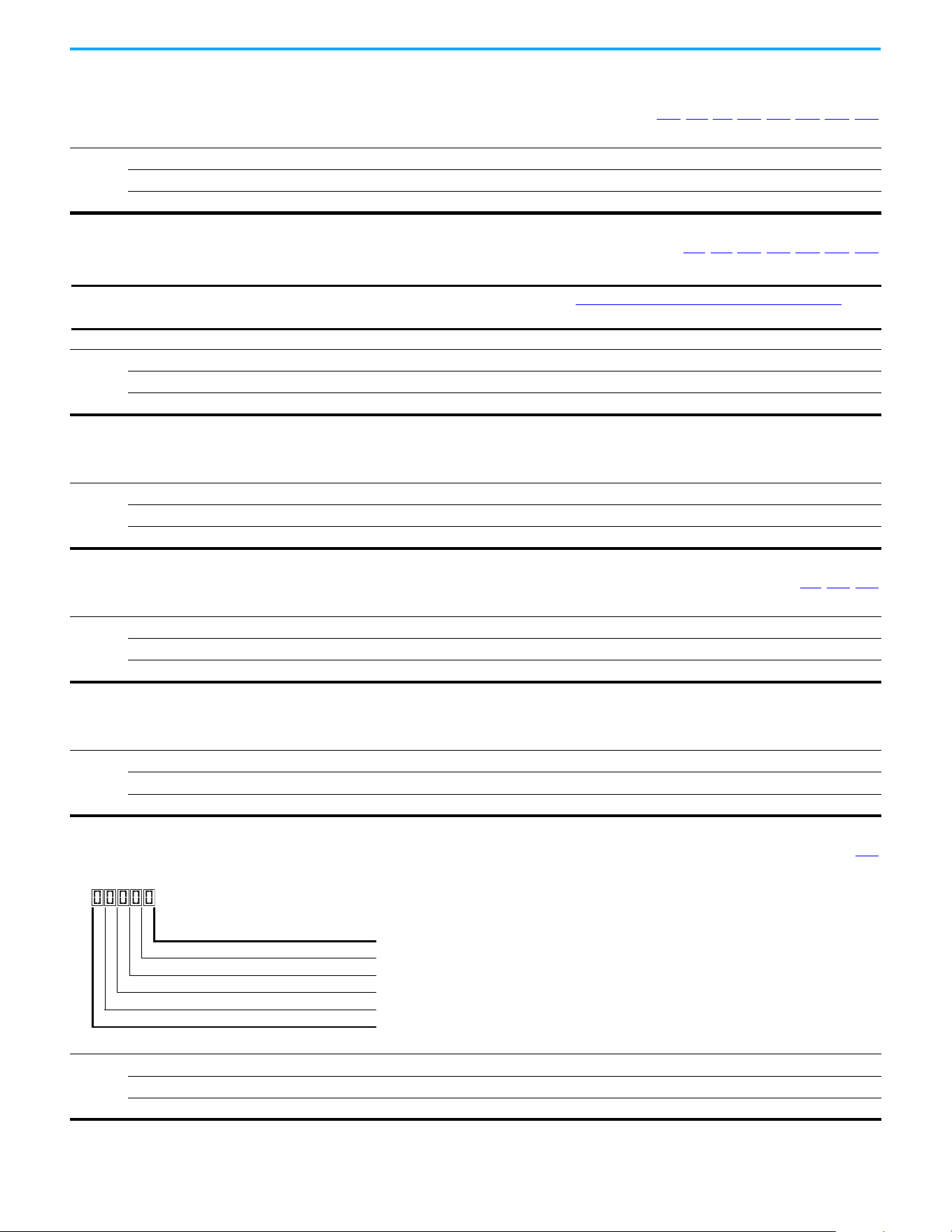
78 Rockwell Automation Publication 520-UM001N-EN-E - July 2024
Chapter 3 Programming and Parameters
Basic Display Group
b001 [Output Freq] Related Parameters: b002, b010, b011, P043, P044, P048, P050, P052
Output frequency present at T1, T2 & T3 (U, V & W). Does not include slip frequency.
Values
Default: Read Only
Min/Max: 0.00/[Maximum Freq]
Display: 0.01 Hz
b002 [Commanded Freq] Related Parameters: b001, b013, P043, P044, P048, P050, P052
Value of the active frequency command even if the drive is not running.
Values
Default: Read Only
Min/Max: 0.00/[Maximum Freq]
Display: 0.01 Hz
IMPORTANT
The frequency command can come from a number of sources. See Start and Speed Reference Control on page 49 for
more information.
b003 [Output Current]
Output current present at T1, T2 & T3 (U, V & W).
Values
Default: Read Only
Min/Max: 0.00/(Drive Rated Amps x 2)
Display: 0.01 A
b004 [Output Voltage] Related Parameters: P031, A530, A534
Output voltage present at T1, T2 & T3 (U, V & W).
Values
Default: Read Only
Min/Max: 0.0/Drive Rated Volts
Display: 0.1V
b005 [DC Bus Voltage]
Filtered DC bus voltage level of the drive.
Values
Default: Read Only
Min/Max: 0/1200V DC
Display: 1V DC
b006 [Drive Status] Related Parameters: A544
Present operating condition of the drive.
Values
Default: Read Only
Min/Max: 00000/11111
Display: 00000
1 = True/Active, 0 = False/Inactive
Running Digit 1
Forward Digit 2
Accelerating Digit 3
Decelerating Digit 4
SafetyActive
(1)
Digit 5
(1) Setting is specific to PowerFlex 525 drives only.

Rockwell Automation Publication 520-UM001N-EN-E - July 2024 79
Chapter 3 Programming and Parameters
Basic Display Group (continued)
b007 [Fault 1 Code] Related Parameters: F604…F610
b008 [Fault 2 Code]
b009 [Fault 3 Code]
A code that represents a drive fault. Codes appear in these parameters in the order that they occur (b007
[Fault 1 Code] = the most recent fault). Repetitive faults are only
recorded once.
See Fault and Diagnostic Group for more information.
Values
Default: Read Only
Min/Max: F0/F127
Display: F0
b010 [Process Display] Related Parameters: b001, A481, A482
32-bit parameter
Output frequency scaled by A481 [Process Disp Lo] and A482 [Process Disp Hi].
Scaled Process Value (PV) = (([Process Disp Hi] - [Process Disp Lo]) x ([Output Freq] - [Minimum Freq])) / ([Maximum Freq] - [Minimum Freq])
Values
Default: Read Only
Min/Max: 0/9999.00
Display: 0.01
32
b011 [Process Fract] Related Parameters: b001, A481, A482
Output frequency (fractional portion) scaled by A481 [Process Disp Lo] and A482 [Process Disp Hi].
Scaled Process Value (PV) = (([Process Disp Hi] - [Process Disp Lo]) x ([Output Freq] - [Minimum Freq])) / ([Maximum Freq] - [Minimum Freq])
Values
Default: Read Only
Min/Max: 0.00/0.99
Display: 0.01
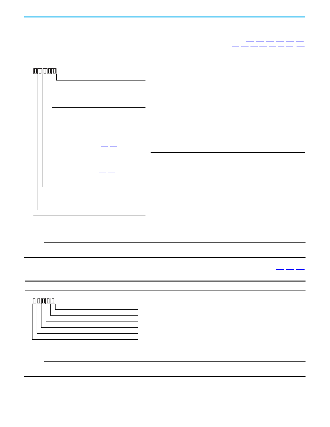
80 Rockwell Automation Publication 520-UM001N-EN-E - July 2024
Chapter 3 Programming and Parameters
Basic Display Group (continued)
b012 [Control Source] Related Parameters: P046, P047, P048, P049, P050, P051,
t062
, t063, t065-t068, L180-L187, A410…A425
Active source of the Start Command and Frequency Command. Normally defined by the settings of P046, P048, P050 [Start Source x] and P047, P049, P051 [Speed
Referencex].
See Start and Speed Reference Control on page 49 for more information.
Values
Default: Read Only
Min/Max: 0000/2165
Display: 0000
Start Command Source Digit 1
1 = Keypad
2 = DigIn TrmBlk (Parameters t062
, t063, t065…t068)
3 = Serial/DSI
4 = Network Opt
(1)
5 = EtherNet/IP
(2)
(1) Select this setting if using the optional PowerFlex 25-COMM-E2P, 25-COMM-D,
or 25-COMM-P adapters as the Start source and/or Frequency source.
(2) Setting is specific to PowerFlex 525 drives only.
Frequency Command Source Digit 2 & 3
00 = Other
01 = Drive Pot
02 = Keypad
03 = Serial/DSI
04 = Network Opt
(1)
05 = 0-10V Input
06 = 4-20mA Input
07 = Preset Freq (Parameters A410
…A425)
08 = Anlg In Mult
(2)
09 = MOP
10 = Pulse Input
11 = PID1 Output
12 = PID2 Output
(2)
13 = Step Logic (Parameters L180…L187)
(1)
14 = Encoder
(2)
15 = EtherNet/IP
(2)
16 = Positioning
(2)
Frequency Command Source Digit 4
0 = Other (Digit 2 & 3 Digits 2 & 3 are used. Digit 4 is not
shown.)
1 = Jog
2 = Purge
Not Used
Example
Display Reads Description
2004 Start source comes from Network Opt and Frequency source is Purge.
113
Start source comes from Serial/DSI and Frequency source comes from
PID1 Output.
155 Start source and Frequency source come from EtherNet/IP.
052
Start source comes from DigIn TrmBlk and Frequency source comes from
0…10V Input.
011
Start source comes from Keypad and Frequency source comes from Drive
Pot.
b013 [Contrl In Status] Related Parameters: b002, P044, P045
State of the digital terminal blocks 1...3 and DB transistor.
Values
Default: Read Only
Min/Max: 0000/1111
Display: 0000
IMPORTANT
Actual control commands may come from a source other than the control terminal block.
1 = Closed State, 0 = Open State
DigIn TBlk 1 Digit 1
DigIn TBlk 2 Digit 2
DigIn TBlk 3 Digit 3
DB Trans On
(1)
Digit 4
(1) The DB Transistor “on” indication must have a 0.5 s hysteresis. It turns on
and stays on for at least 0.5 s every time the DB transistor is turned on.
Not Used

Rockwell Automation Publication 520-UM001N-EN-E - July 2024 81
Chapter 3 Programming and Parameters
Basic Display Group (continued)
b014 [Dig In Status] Related Parameters: t065…t068
State of the programmable digital inputs.
Values
Default: Read Only
Min/Max: 0000/1111
Display: 0000
1 = Closed State, 0 = Open State
DigIn TBlk 5 Digit 1
DigIn TBlk 6 Digit 2
DigIn TBlk 7
(1)
Digit 3
(1) Setting is specific to PowerFlex 525 drives only.
DigIn TBlk 8
(1)
Digit 4
Not Used
b015 [Output RPM] Related Parameters: P035
Current output frequency in rpm. Scale is based on P035 [Motor NP Poles].
Values
Default: Read Only
Min/Max: 0/24000 rpm
Display: 1 rpm
b016 [Output Speed] Related Parameters: P044
Current output frequency in %. Scale is 0% at 0.00 Hz to 100% at P044 [Maximum Freq].
Values
Default: Read Only
Min/Max: 0.0/100.0%
Display: 0.1%
b017 [Output Power] Related Parameters: b018
Output power present at T1, T2 & T3 (U, V & W).
Values
Default: Read Only
Min/Max: 0.00/(Drive Rated Power x 2)
Display: 0.01 kW
b018 [Power Saved] Related Parameters: b017
Instantaneous power savings of using this drive compared to an across the line starter.
Values
Default: Read Only
Min/Max: 0.00/655.35 kW
Display: 0.01 kW
b019 [Elapsed Run time] Related Parameters: A555
Accumulated time drive is outputting power. Time is displayed in 10-hour increments.
Values
Default: Read Only
Min/Max: 0/65535 x 10 hr
Display: 1 = 10 hr

82 Rockwell Automation Publication 520-UM001N-EN-E - July 2024
Chapter 3 Programming and Parameters
Basic Display Group (continued)
b020 [Average Power] Related Parameters: A555
Average power that is used by the motor since the last reset of the meters.
Values
Default: Read Only
Min/Max: 0.00/(Drive Rated Power x 2)
Display: 0.01 kW
b021 [Elapsed kWh] Related Parameters: b022
Accumulated output energy of the drive. When the maximum value of this parameter is reached, it resets to zero and b022 [Elapsed MWh] is incremented.
Values
Default: Read Only
Min/Max: 0.0/100.0 kWh
Display: 0.1 kWh
b022 [Elapsed MWh] Related Parameters: b021
Accumulated output energy of the drive.
Values
Default: Read Only
Min/Max: 0.0/6553.5 MWh
Display: 0.1 MWh
b023 [Energy Saved] Related Parameters: A555
Total energy savings of using this drive compared to an across the line starter since the last reset of the meters.
Values
Default: Read Only
Min/Max: 0.0/6553.5 kWh
Display: 0.1 kWh
b024 [Accum kWh Sav] Related Parameters: b025
Total approximate accumulated energy savings of the drive compared to using an across the line starter.
Values
Default: Read Only
Min/Max: 0.0/6553.5 kWh
Display: 0.1 = 10 kWh
b025 [Accum Cost Sav] Related Parameters: b024, P052, A555
Total approximate accumulated cost savings of the drive compared to using an across the line starter.
[Accum Cost Sav] = [Average kWh cost] x [Accum kWh Sav]
Values
Default: Read Only
Min/Max: 0.0/6553.5
Display: 0.1
b026 [Accum CO2 Sav] Related Parameters: A555
Total approximate accumulated CO2 savings of the drive compared to using an across the line starter.
Values
Default: Read Only
Min/Max: 0.0/6553.5 kg
Display: 0.1 kg

Rockwell Automation Publication 520-UM001N-EN-E - July 2024 83
Chapter 3 Programming and Parameters
Basic Display Group (continued)
b027 [Drive Temp]
Present operating temperature of the drive heatsink (inside module).
Values
Default: Read Only
Min/Max: 0/120 °C
Display: 1 °C
b028 [Control Temp]
Present operating temperature of the drive control.
Values
Default: Read Only
Min/Max: 0/120 °C
Display: 1 °C
b029 [Control SW Ver]
Current drive firmware revision.
Values
Default: Read Only
Min/Max: 0.000/65.535
Display: 0.001
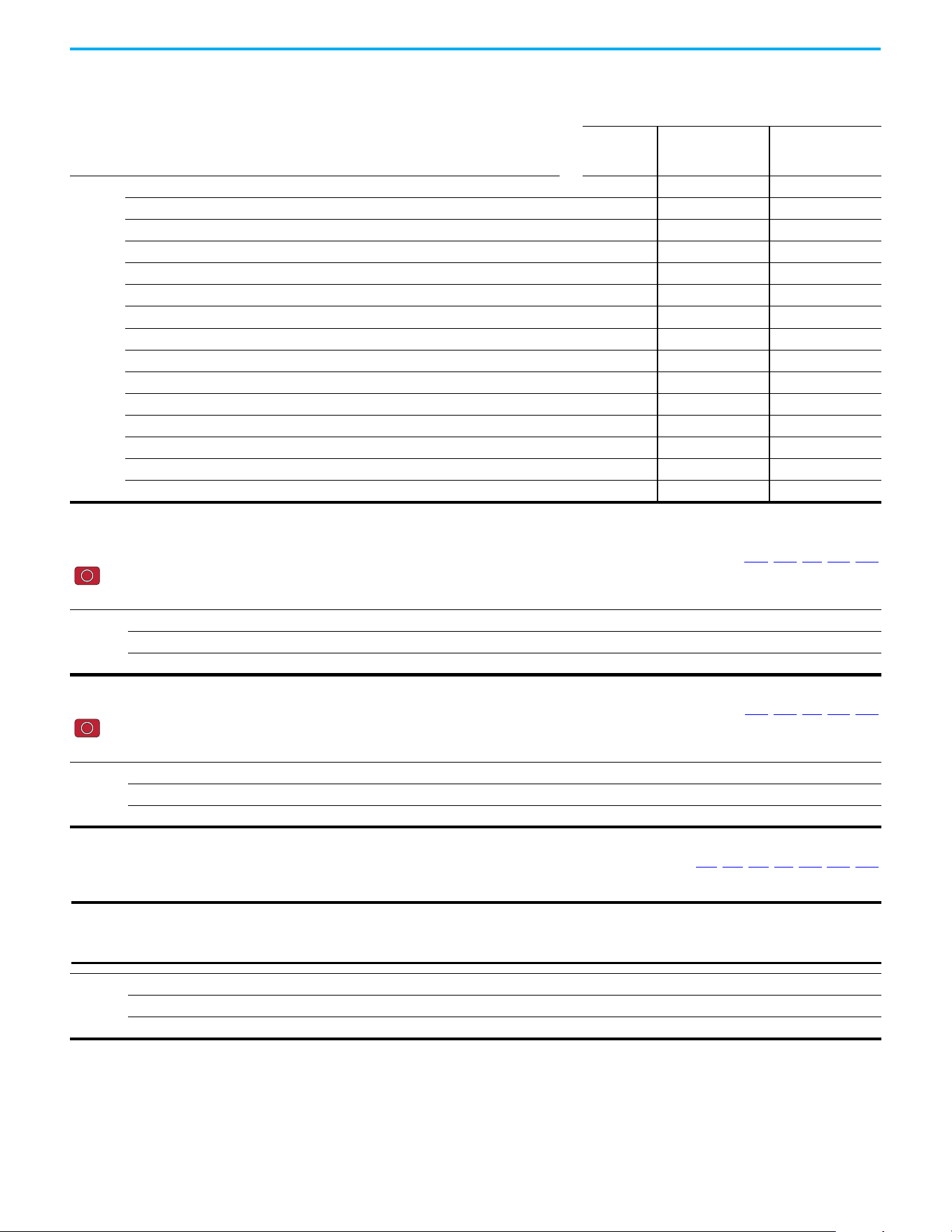
84 Rockwell Automation Publication 520-UM001N-EN-E - July 2024
Chapter 3 Programming and Parameters
Basic Program Group
P030 [Language] Language Support
Selects the language displayed. A reset or power cycle is required after selection is made.
Keypad/
LCD Display
RSLogix 5000/Logix
Designer application
Connected
Components
Workbench software
Options
1English (Default) Y Y Y
2Français Y Y Y
3Español Y Y Y
4Italiano Y Y Y
5 Deutsch Y Y Y
6 Japanese — Y —
7Português Y Y —
8 Chinese Simplified Chinese — Y Y
9 Reserved
10 Reserved
11 Korean — Y —
12 Polish
(1)
Y— —
13 Reserved
14 Turkish
(1)
Y— —
15 Czech
(1)
Y— —
(1) Due to a limitation of the LCD Display, some of the characters for Polish, Turkish, and Czech is modified.
P031 [Motor NP Volts] Related Parameters: b004, A530, A531, A532, A533
Stop drive before changing this parameter.
Sets the motor nameplate rated volts.
Values
Default: Drive Rated Volts
Min/Max: 10V (for 230V Drives), 20V (for 460V Drives), 25V (for 600V Drives)/Drive Rated Volts
Display: 1V
P032 [Motor NP Hertz] Related Parameters: A493, A530, A531, A532, A533
Stop drive before changing this parameter.
Sets the motor nameplate rated frequency.
Values
Default: 60 Hz
Min/Max: 15/500 Hz
Display: 1 Hz
P033 [Motor OL Current] Related Parameters: t069, t072, t076, t081, A484, A485, A493
Sets the motor nameplate overload current. Used to determine motor overload conditions and can be set from 0.1 A to 200% of drive rated current.
Values
Default: Drive Rated Amps
Min/Max: 0.0/(Drive Rated Amps x 2)
Display: 0.1 A
IMPORTANT
The drive will fault on an F007 “Motor Overload” if the value of this parameter is exceeded based on class 10 motor
overload protection according to NEC article 430 and motor over-temperature protection according to NEC article
430.126 (A) (2). UL 508C File 29572.
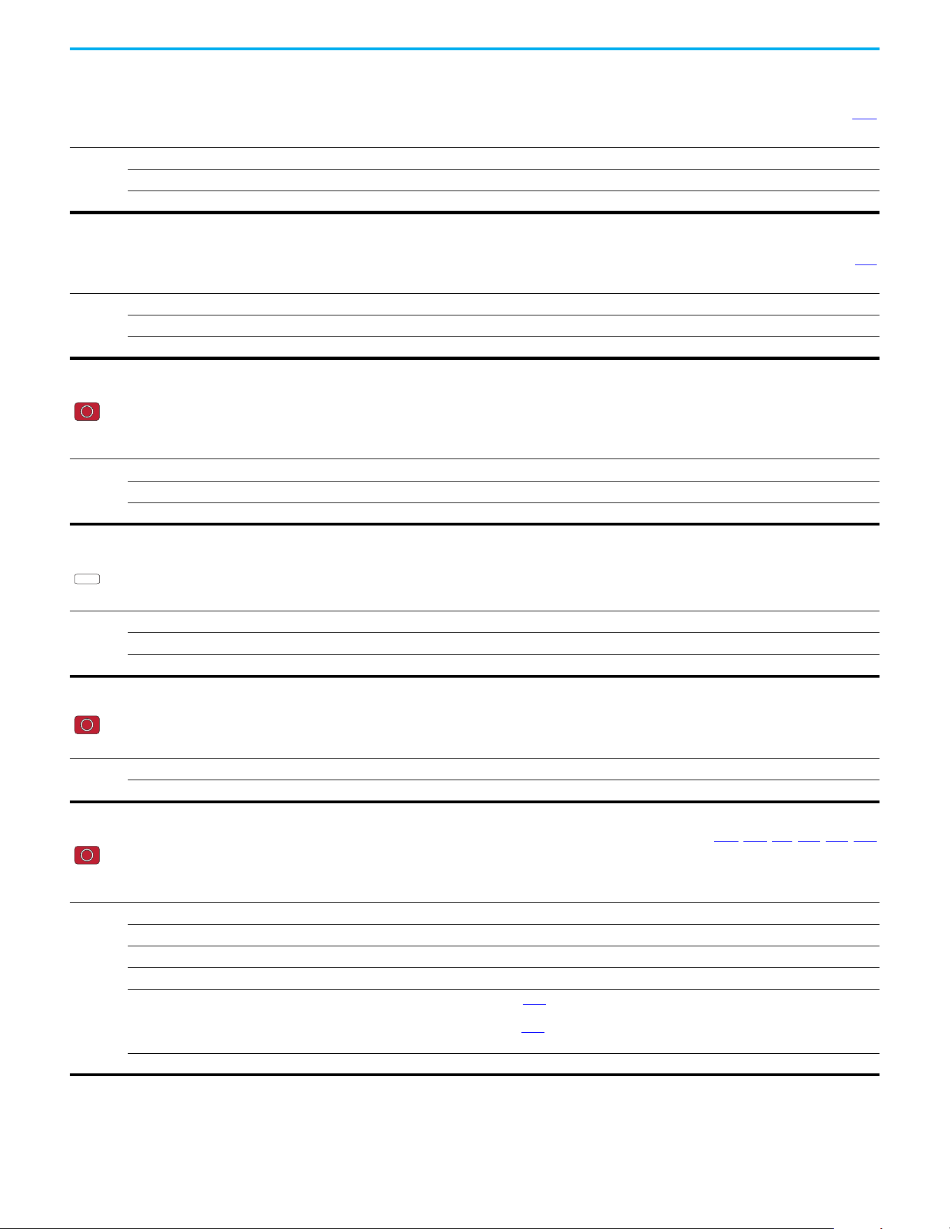
Rockwell Automation Publication 520-UM001N-EN-E - July 2024 85
Chapter 3 Programming and Parameters
Basic Program Group (continued)
P034 [Motor NP FLA] Related Parameters: P040
Sets the motor nameplate FLA. Used to assist the Autotune routine and motor control.
Values
Default: Based on Drive Rating
Min/Max: 0.1/(Drive Rated Amps x 2)
Display: 0.1 A
P035 [Motor NP Poles] Related Parameters: b015
Sets the number of poles in the motor.
Values
Default: 4
Min/Max: 2/40
Display: 1
P036 [Motor NP RPM]
Stop drive before changing this parameter.
Sets the rated nameplate rpm of the motor. Used to calculate the rated slip of the motor. To reduce the slip frequency, set this parameter closer to the motor synchronous
speed.
Values
Default: 1750 rpm
Min/Max: 0/24000 rpm
Display: 1 rpm
P037 [Motor NP Power]
PowerFlex 525 only
Sets the motor nameplate power. Used in PM regulator.
Values
Default: Drive Rated Power
Min/Max: 0.00/Drive Rated Power
Display: 0.01 kW
PF 525
P038 [Voltage Class]
Stop drive before changing this parameter.
Sets the voltage class of 600V drives.
Options
2 “Low Voltage” 480V
3 “High Voltage” (Default) 600V
P039 [Torque Perf Mode] Related Parameters: P040, A530, A531, A532, A533, A535
Stop drive before changing this parameter.
Selects the motor control mode.
The PowerFlex 523 and PowerFlex 525 drives are capable of performing with the following motor control modes.
Options
0“V/Hz”
1“SVC” (Default)
2 “Economize”
3“Vector”
(1)
Voltage Vector only (cannot control torque). It is recommended to use with an encoder when using VVC mode.
4“PM Control”
(1)
(2)
When P039 [Torque Perf Mode] is set to 4 and A535 [Motor Fdbk Type] is set to 0, 1, 2 or 3, the drive is in open loop PM
motor control mode.
When P039 [Torque Perf Mode] is set to 4 and A535
[Motor Fdbk Type] is set to 4 or 5, the drive is in closed loop PM motor
control mode.
5“SynRM”
(3)
Set P039 [Torque Perf Mode] to 5 to enable the use of Synchronous Reluctance Motor control.
(1) Setting is specific to PowerFlex 525 drives only.
(2) Setting is available in PowerFlex 525 FRN 5.xxx and later.
(3) Setting is available in PowerFlex 525 FRN 7.xxx and later.
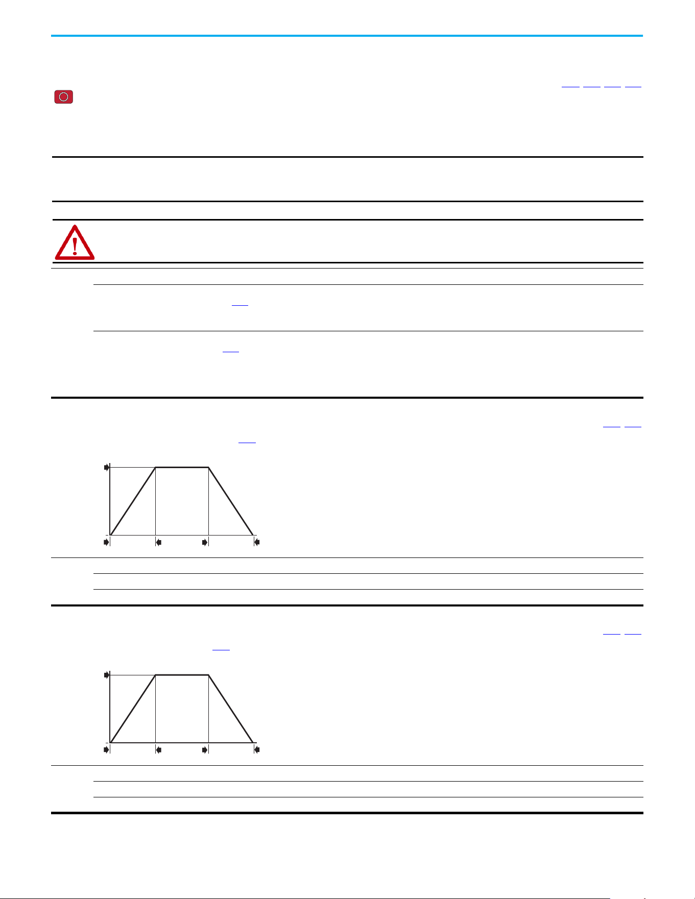
86 Rockwell Automation Publication 520-UM001N-EN-E - July 2024
Chapter 3 Programming and Parameters
Basic Program Group (continued)
P040 [Autotune] Related Parameters: P034, P039, A496, A497
Stop drive before changing this parameter.
Enables a static (not spinning) or dynamic (motor spinning) autotune to automatically set the motor parameters. Set the parameter value to a one or two, then issue a valid
“Start” command to begin the routine. After the routine is complete the parameter resets to a zero. A failure (such as if a motor is not connected) results in an Autotune
Fault.
It is recommended to perform a full rotate tune when using VVC mode.
Options
0 “Ready/Idle” (Default)
1 “Static Tune” A temporary command that initiates a non-rotational motor stator resistance test for the best possible automatic setting
of A496 [IR Voltage Drop]. A start command is required following initiation of this setting. The parameter returns to 0
“Ready/Idle” following the test, at which time another start transition is required to operate the drive in normal mode.
Used when motor cannot be uncoupled from the load.
2 “Rotate Tune” A temporary command that initiates a “Static Tune” followed by a rotational test for the best possible automatic setting of
A497
[Flux Current Ref]. A start command is required following initiation of this setting. The parameter returns to 0
“Ready/Idle” following the test, at which time another start transition is required to operate the drive in normal mode.
Important: Used when motor is uncoupled from the load. Results may not be valid if a load is coupled to the motor during
this procedure.
If [P039 = 5], it is the same with “Static Tune”.
IMPORTANT
All motor parameters in the Basic Program group must be set before running the routine. If a start command is not
given (or a stop command is given) within 30 s, the parameter automatically returns to a zero and an Autotune Fault
occurs.
ATTENTION: Rotation of the motor in an undesired direction can occur during this procedure. To guard against possible
injury and/or equipment damage, it is recommended that the motor be disconnected from the load before proceeding.
P041 [Accel Time 1] Related Parameters: P044, A439
Sets the time for the drive to accelerate from 0 Hz to P044 [Maximum Freq].
Accel Rate = [Maximum Freq] / [Accel Time x]
Values
Default: 10.00 s
Min/Max: 0.00/600.00 s
Display: 0.01 s
Speed
0
Time
[Maximum Freq]
[Accel Time x]
[Decel Time x]
0
Acceleration
Deceleration
P042 [Decel Time 1] Related Parameters: P044, A439
Sets the time for the drive to decelerate from P044 [Maximum Freq] to 0 Hz.
Decel Rate = [Maximum Freq] / Decel Time x]
Values
Default: 10.00 s
Min/Max: 0.00/600.00 s
Display: 0.01 s
Speed
0
Time
[Maximum Freq]
[Accel Time x]
[Decel Time x]
0
Acceleration
Deceleration
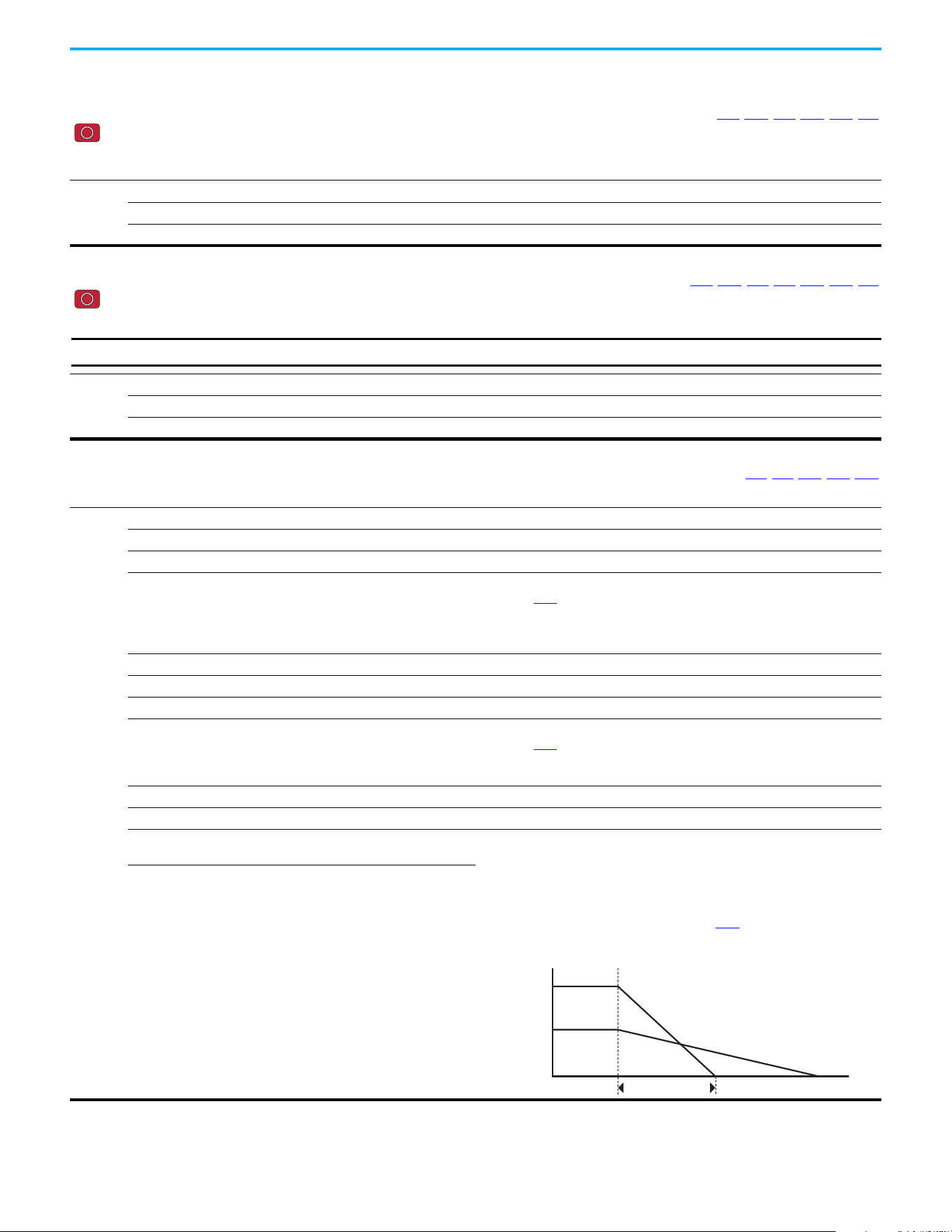
Rockwell Automation Publication 520-UM001N-EN-E - July 2024 87
Chapter 3 Programming and Parameters
Basic Program Group (continued)
P043 [Minimum Freq] Related Parameters: b001, b002, b013, P044, A530, A531
Stop drive before changing this parameter.
Sets the lowest frequency the drive outputs.
Although this parameter can be set greater than P044 [Maximum Freq], the drive uses P044 [Maximum Freq] to determine the actual maximum frequency.
Values
Default: 0.00 Hz
Min/Max: 0.00/500.00 Hz
Display: 0.01 Hz
P044 [Maximum Freq] Related Parameters: b001, b002, b013, b016, P043, A530, A531
Stop drive before changing this parameter.
Sets the highest frequency the drive outputs.
Values
Default: 60.00 Hz
Min/Max: 0.00/500.00 Hz
Display: 0.01 Hz
IMPORTANT
This value must be greater than the value set in P043 [Minimum Freq].
P045 [Stop Mode] Related Parameters: t086, t087, A434, A435, A550
Determines the stopping mode that is used by the drive when a stop is initiated.
Options
0 “Ramp, CF” (Default) Ramp to Stop. Stop command clears active fault.
1 “Coast, CF” Coast to Stop. Stop command clears active fault.
2 “DC Brake, CF” DC Injection Braking Stop. Stop command clears active fault.
3 “DC BrkAuto,CF” DC Injection Braking Stop with Auto Shutoff.
• Standard DC Injection Braking for value set in A434
[DC Brake Time].
OR
• Drive shuts off if the drive detects that the motor is stopped.
Stop command clears active fault.
4 “Ramp” Ramp to Stop.
5 “Coast” Coast to Stop.
6 “DC Brake” DC Injection Braking Stop.
7 “DC BrakeAuto” DC Injection Braking Stop with Auto Shutoff.
• Standard DC Injection Braking for value set in A434
[DC Brake Time].
OR
• Drive shuts off if the drive detects that the motor is stopped.
8 “Ramp+EM B,CF” Ramp to Stop with EM Brake Control. Stop command clears active fault.
9 “Ramp+EM Brk” Ramp to Stop with EM Brake Control.
10 “PointStp,CF” PointStop. Stop command clears
active fault.
Provides a method to stop at a constant distance instead of a fixed rate.
When a Stop command is given, the distance that is required for the machine to
travel to standstill based on the programmed maximum speed and deceleration time
is calculated. If the drive is running slower than the maximum speed, the function
applies a calculated deceleration time that allows the machine to travel to standstill
in the same distance based on the current speed.
It is recommended to use braking resistors or set A550
[Bus Reg Enable] to 0
“Disabled” for better performance.
11 “PointStop”
PointStop.
Speed
Time
[Maximum Freq]
Stop
Calculated Stop Time
[Decel Time x]

88 Rockwell Automation Publication 520-UM001N-EN-E - July 2024
Chapter 3 Programming and Parameters
Basic Program Group (continued)
P046 [Start Source 1] Related Parameters: b012, t064, C125
P048 [Start Source 2]
P050 [Start Source 3]
Stop drive before changing this parameter.
Configures the start source of the drive. Changes to these inputs take effect as soon as they are entered. P046 [Start Source 1] is the factory default start source unless
overridden.
See Start and Speed Reference Control on page 49 for more information.
Options
1 “Keypad” [Start Source 1] default
2 “DigIn TrmBlk” [Start Source 2] default
3 “Serial/DSI” [Start Source 3] default for PowerFlex 523
4 “Network Opt”
(1)
5“EtherNet/IP”
(2)
[Start Source 3] default for PowerFlex 525
(1) Select this setting if using the optional PowerFlex 25-COMM-E2P, 25-COMM-D, or 25-COMM-P adapters as the start source.
(2) Setting is specific to PowerFlex 525 drives only.
IMPORTANT
For all settings except when t064 [2-Wire Mode] is set to 1 “Level Sense”, the drive must receive a leading edge from
the start input for the drive to start after a stop input, loss of power, or fault condition.
P047 [Speed Reference1] Related Parameters: C125
P049 [Speed Reference2]
P051 [Speed Reference3]
Selects the source of speed command for the drive. Changes to these inputs take effect as soon as they are entered. P047 [Speed Reference1] is the factory default speed
reference unless overridden.
See Start and Speed Reference Control on page 49
for more information.
Options
1 “Drive Pot” [Speed Reference1] default
2“Keypad Freq”
3 “Serial/DSI” [Speed Reference3] default for PowerFlex 523
4 “Network Opt”
(1)
5 “0-10V Input” [Speed Reference2] default
6 “4-20mA Input”
7 “Preset Freq”
8 “Anlg In Mult”
(2)
9“MOP”
10 “Pulse Input”
11 “PID1 Output”
12 “PID2 Output”
(2)
13 “Step Logic”
(2)
14 “Encoder”
(2)
15 “EtherNet/IP”
(2)
[Speed Reference3] default for PowerFlex 525
16 “Positioning”
(2)
Referencing from A558 [Positioning Mode]
(1) Select this setting if using the optional PowerFlex 25-COMM-E2P, 25-COMM-D, or 25-COMM-P adapters as the speed reference.
(2) Setting is specific to PowerFlex 525 drives only.
P052 [Average kWh Cost] Related Parameters: b025
Sets the average cost per kWh.
Values
Default: 0.00
Min/Max: 0.00/655.35
Display: 0.01

Rockwell Automation Publication 520-UM001N-EN-E - July 2024 89
Chapter 3 Programming and Parameters
Basic Program Group (continued)
Basic Program Grou p (continued)
P053 [Reset To Defalts]
Stop drive before changing this parameter.
Resets all parameters to their factory default values. After a Reset command, the value of this parameter returns to zero.
Options
0 “Ready/Idle” (Default)
1 “Param Reset” Does not reset custom groups, parameter P030 [Language], and communication parameters.
2 “Factory Rset” Restore drive to factory condition.
3 “Power Reset” Resets only power parameters. Can be used when swapping power modules.
4 “Module Reset”
(1)
(2)
Power cycle of the drive, NO parameters are reset.
(1) Setting is available in PowerFlex 525 FRN 5.xxx and later.
(2) Setting is available in PowerFlex 523 FRN 3.xxx and later.
Parameters that are Reset when P053 = 3
Parameter Name
P031 [Motor NP Volts]
P033 [Motor OL] Current
P034 [Motor NP FLA]
P035 [Motor NP Poles]
A435 [DC Brake Level]
A484 [Current Limit 1]
A485 [Current Limit 2]
A486 [Shear Pin1 Level]
A488 [Shear Pin2 Level]
A490 [Load Loss Level]
A496 [IR Voltage Drop]
A497 [Flux Current Ref]
A530 [Boost Select]
A531 [Start Boost]
A532 [Break Voltage]
A533 [Break Frequency]
A534 [Maximum] Voltage
Parameters that are NOT Reset when P053 = 1
Parameter Parameter Parameter
P030 [Language] C138 [EN Gateway Cfg 2] C159 [EN Data Out 3]
C121 [Comm Write Mode] C139 [EN Gateway Cfg 3] C160 [EN Data Out 4]
C122 [Cmd Stat Select] C140 [EN Gateway Cfg 4] C161 [Opt Data In 1]
C123 [RS485 Data Rate] C141 [EN Rate Cfg] C162 [Opt Data In 2]
C124 [RS485 Node Addr] C143 [EN Comm Flt Actn] C163 [Opt Data In 3]
C124 [Comm Loss Action] C144 [EN Idle Flt Actn] C164 [Opt Data In 4]
C126 [Comm Loss Time] C145 [EN Flt Cfg Logic] C165 [Opt Data Out 1]
C127 [RS485 Format] C146 [EN Flt Cfg Ref] C166 [Opt Data Out 2]
C128 [EN Addr Sel] C147 [EN Flt Cfg DL 1] C167 [Opt Data Out 3]
C129 [EN IP Addr Cfg 1] C148 [EN Flt Cfg DL 2] C168 [Opt Data Out 4]
C130 [EN IP Addr Cfg 2] C149 [EN Flt Cfg DL 3] C169 [MultiDrv Sel]
C131 [EN IP Addr Cfg 3] C150 [EN Flt Cfg DL 4] C171 [Drv 1 Addr]
C132 [EN IP Addr Cfg 4] C153 [EN Data In 1] C172 [Drv 2 Addr]
C133 [EN Subnet Cfg 1] C154 [EN Data In 2] C173 [Drv 3 Addr]
C134 [EN Subnet Cfg 2] C155 [EN Data In 3] C174 [Drv 4 Addr]
C135 [EN Subnet Cfg 3] C156 [EN Data In 4] C175 [DSI I/O Cfg]
C136 [EN Subnet Cfg 4] C157 [EN Data Out 1]
GC [Parameters in Custom
Group]
C137 [EN Gateway Cfg 1] C158 [EN Data Out 2]
P054 [Display Param] Related Parameters: b001
Sets the parameter to display on the drive LCD display when the drive powers up.
Options
0 “Keypad Disp” (Default) Without ADC = shows last selected display parameter
With ADC = shows parameter b001
[Output Freq]
1 “Output Freq” Basic Display group parameters
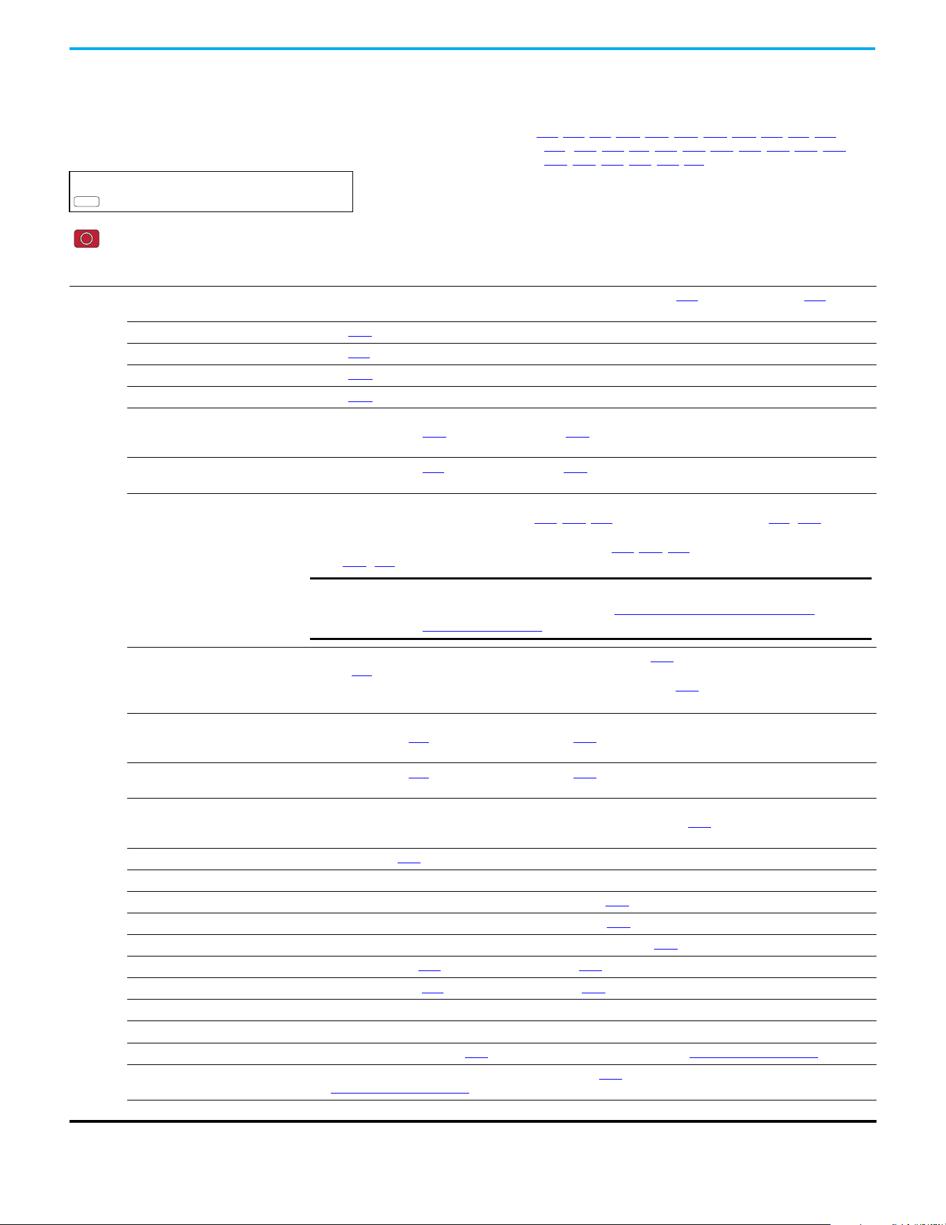
90 Rockwell Automation Publication 520-UM001N-EN-E - July 2024
Chapter 3 Programming and Parameters
Terminal Block Group
Programmable Digital Inputs
t062 [DigIn TermBlk 02]
t065 [DigIn TermBlk 05]
t063 [DigIn TermBlk 03]
t066 [DigIn TermBlk 06]
Related Parameters: b012, b013, b014, P045, P046, P048, P049, P050, P051, t064, t086,
A410…A425, A427, A431, A432, A433, A434, A435, A442, A443, A488,
A535, A560, A562, A563, A567, A571
t067 [DigIn TermBlk 07]
PowerFlex 525 only
t068 [DigIn TermBlk 08]
Stop drive before changing this parameter.
Programmable digital input. Changes to these inputs take effect as soon as they are entered. If a digital input is set for a selection that is only usable on one input, no other
input can be set for the same selection.
Options
0 “Not Used” Terminal has no function but can be read over network communications with b013
[Contrl In Status] and b014 [Dig In
Status].
1 “Speed Ref 2” Selects P049 [Speed Reference2] as drive's speed command.
2 “Speed Ref 3” Selects P051
[Speed Reference3] as drive's speed command.
3 “Start Src 2” Selects P048
[Start Source 2] as control source to start the drive.
4 “Start Src 3” Selects P050 [Start Source 3] as control source to start the drive.
5 “Spd + Strt 2” [DigIn TermBlk 07] default.
Selects combination of P049
[Speed Reference2] and P048 [Start Source 2] as speed command with control source to
start the drive.
6 “Spd + Strt 3” Selects combination of P051
[Speed Reference3] and P050 [Start Source 3] as speed command with control source to
start the drive.
7 “Preset Freq”
(PF523: only for DigIn TermBlk 03, 05,
and 06)
(PF525: only for DigIn TermBlk
05...08)
[DigIn TermBlk 05] and [DigIn TermBlk 06] default.
• Selects a preset frequency in Velocity mode (P047
, P049, P051 [Speed Referencex] = 1...15). See A410…A425 [Preset
Freq x].
• Selects a preset frequency and position in Positioning mode (P047
, P049, P051 [Speed Referencex] = 16).
See L200…L214 [Step Units x] (only for PowerFlex 525 drives).
8 “Jog” • When input is present, drive accelerates according to the value set in A432
[Jog Accel/Decel] and ramps to the value
set in A431 [Jog Frequency].
• When input is removed, drive ramps to a stop according to the value set in A432
[Jog Accel/Decel].
• A valid Start command overrides this input.
9 “Jog Forward” [DigIn TermBlk 08] default.
Drive accelerates to A431
[Jog Frequency] according to A432 [Jog Accel/Decel] and ramps to a stop when input
becomes inactive. A valid Start command overrides this input.
10 “Jog Reverse” Drive accelerates to A431
[Jog Frequency] according to A432 [Jog Accel/Decel] and ramps to a stop when input
becomes inactive. A valid Start command overrides this input.
11 “Acc/Dec Sel2”
(1)
If active, determines which Accel/Decel time is used for all ramp rates except jog.
Can be used with option 29 “Acc/Dec Sel3” for additional Accel/Decel times. See A442 [Accel Time 2] for more
information.
12 “Aux Fault” When enabled, an F002
“Auxiliary Input” fault occurs when the input is removed.
13 “Clear Fault” When active, clears an active fault.
14 “RampStop,CF” Causes drive to immediately ramp to a stop regardless of how P045
[Stop Mode] is set.
15 “CoastStop,CF” Causes drive to immediately coast to a stop regardless of how P045
[Stop Mode] is set.
16 “DCInjStop,CF” Causes drive to immediately begin a DC Injection stop regardless of how P045
[Stop Mode] is set.
17 “MOP Up” Increases the value of A427
[MOP Freq] at the rate set in A430 [MOP Time].
18 “MOP Down” Decreases the value of A427
[MOP Freq] at the rate set in A430 [MOP Time].
19 “Timer Start”
(1)
Clears and starts the timer function. May be used to control the relay or opto outputs.
20 “Counter In”
(1)
Starts the counter function. May be used to control the relay or opto outputs.
21 “Reset Timer” Resets the internal active timer, d365 [Timer Status]. For more information, see Timer Function on page 215.
22 “Reset Countr” Resets the count in the accumulated internal active counter, d364
[Counter Status]. For more information,
see Counter Function on page 216.
23 “Rset Tim&Cnt” Resets both the internal active timer and accumulated internal active counter.
PF 525
IMPORTANT
Digital Inputs have priority for frequency control when programmed as
Preset Speed and are active. See Start Source and Speed Reference
Selection on page 49 for more information.
Rockwell Automation Publication 520-UM001N-EN-E - July 2024 91
Chapter 3 Programming and Parameters
Options
24 “Logic In 1”
(1)(2)
Logic function input number 1. May be used to control the relay or opto outputs (t076, t081 [Relay Outx Sel] and
t069, t072 [Opto Outx Sel], options 11...14). May be used with StepLogic parameters L180…L187 [Stp Logic x].
25 “Logic In 2”
(1)(2)
Logic function input number 2. May be used to control the relay or opto outputs (t076, t081 [Relay Outx Sel] and
t069, t072 [Opto Outx Sel], options 11...14). May be used with StepLogic parameters L180…L187 [Stp Logic x].
26 “Current Lmt2”
(2)
When active, A485 [Current Limit 2] determines the drive current limit level.
27 “Anlg Invert” Inverts the scaling of the analog input levels set in t091 [Anlg In 0-10V Lo] and t092 [Anlg In 0-10V Hi], or t095 [Anlg In4-
20mA Lo] and t096 [Anlg In4-20mA Hi].
28 “EM Brk Rlse” If EM brake function is enabled, this input releases the brake. See t086
[EM Brk Off Delay] for more information.
29 “Acc/Dec Sel3”
(1)
If active, determines which Accel/Decel time is used for all ramp rates except jog.
Used with option 11 “Acc/Dec Sel2” for the Accel/Decel times listed in this table.
30 “Precharge En” Forces drive into precharge state. Typically controlled by auxiliary contact on the disconnect at the DC input to the
drive. If this input is assigned, it must be energized for the precharge relay to close and for the drive to run. If it is de-
energized, the pre-charge relay opens and the drive coasts to a stop.
31 “Inertia Dcel” Forces drive into Inertia ride-through state. The drive attempts to regulate the DC bus at the current level.
32 “Sync Enable” Must be used to hold the existing frequency when Sync Time is set to enable speed synchronization. When this input is
released the drive accelerates to the commanded frequency in A571 [Sync Time].
33 “Traverse Dis” When an input is programmed the traverse function is disabled while this input is active. See A567
[Max Traverse].
34 “Home Limit”
(2)
In Positioning mode, indicates that the drive is at the home position. See Appendix E for more information on
Positioning.
35 “Find Home”
(2)
In Positioning mode, causes the drive to return to the Home position when a Start command is issued.
Uses A562 [Find Home Freq] and A563 [Find Home Dir] until the “Home Limit” input is activated. If it passes this point, it
then runs in the reverse direction at 1/10th the frequency of [Find Home Freq] until the “Home Limit” is activated again.
As long as this input is active, any start command causes the drive to enter the homing routine. Only functions if in
Positioning mode. Once the Find Home routine has finished, the drive stops. See Appendix E for more information on
Positioning.
36 “Hold Step”
(2)
In Positioning mode, overrides other inputs and causes the drive to remain at its current step (running at zero speed
once it reaches its position) until released.
While in “Hold”, the drive ignores any input command that would normally result in a move to a new step. Timers
continue to run. Therefore, when the Hold is removed, the drive must see any required digital inputs transition (even if
they already transitioned during the hold), but it does not reset any timer. See Appendix E
for more information on
Positioning.
37 “Pos Redefine”
(2)
In Positioning mode, resets the home position to the current position of the machine. See Appendix E for more
information on Positioning.
38 “Force DC” If the drive is not running, causes the drive to apply a DC Holding current (A435
[DC Brake Level], ignoring A434 [DC
Brake Time]) while the input is applied.
39 “Damper Input” When active, drive is allowed to run normally.
When inactive, drive is forced into sleep mode and is prevented from accelerating to command speed.
40 “Purge”
(1)
Starts the drive at A433 [Purge Frequency] regardless of the selected control source. Supersedes the keypad Control
function and any other control command to take control of the drive. Purge can occur, and is operational, at any time
whether the drive is running or stopped regardless of the selected logic source selection. If a valid stop (other than from
comms or SW enable) is present, the drive will not start on the purge input transition.
41 “Freeze-Fire” When inactive, causes an immediate F094
“Function Loss” fault. Use to safely bypass the drive with an external
switching device.
42 “SW Enable” Works like an interlock that has to be active for the drive to run.
Programmable Digital Inputs (Continued)
ATTENTION: If a hazard of injury due to movement of equipment or material
exists, an auxiliary mechanical braking device must be used.
Option
Description
29 11
0 0 Acc/Dec 1
0 1 Acc/Dec 2
1 0 Acc/Dec 3
1 1 Acc/Dec 4
ATTENTION: If a hazard of injury due to movement of equipment or material
exists, an auxiliary mechanical braking device must be used.
92 Rockwell Automation Publication 520-UM001N-EN-E - July 2024
Chapter 3 Programming and Parameters
Options
43 “SherPin1 Dis” Disables shear pin 1 but leaves shear pin 2 active. If A488
[Shear Pin 2 Level] is greater than 0.0 A, shear pin 2 is
enabled.
44 Reserved
45 Reserved
46 Reserved
47 Reserved
48 “2-Wire FWD”
(only for DigIn TermBlk 02)
[DigIn TermBlk 02] default. Select 2-Wire FWD for this input.
Select this option and set P046
, P048, or P050 [Start Source x] to 2 “DigIn
TrmBlk” to configure [Start Source x] to a 2-wire run forward mode. Also see
t064 [2-Wire Mode] for level trigger settings.
49 “3-Wire Start”
(only for DigIn TermBlk 02)
Select 3-Wire Start for this input.
Select this option and set P046
, P048, or P050 [Start Source x] to 2 “DigIn
TrmBlk” to configure [Start Source x] to a 3-wire start mode.
50 “2-Wire REV”
(only for DigIn TermBlk 03)
[DigIn TermBlk 03] default. Select 2-Wire REV for this input.
Select this option and set P046
, P048, or P050 [Start Source x] to 2 “DigIn
TrmBlk” to configure [Start Source x] to a 2-wire run reverse mode. Also see
t064 [2-Wire Mode] for level trigger settings.
For PowerFlex 523 drives, this setting is disabled If [DigIn TermBlk 03] is set to
7 “Preset Freq”.
51 “3-Wire Dir”
(only for DigIn TermBlk 03)
Select 3-Wire Dir for this input.
Select this option and set P046
, P048, or P050 [Start Source x] to 2 “DigIn
TrmBlk” to change the direction of [Start Source x].
For PowerFlex 523 drives, this setting is disabled If [DigIn TermBlk 03] is set to
7 “Preset Freq”.
52 “Pulse Train”
(PF523: only for DigIn TermBlk 05)
(PF525: only for DigIn TermBlk 07)
Select pulse train for this input.
Use P047
, P049, and P051 [Speed Referencex] to select pulse input.
Jumper for DigIn TermBlk 05 or 07 Sel must be moved to Pulse In.
(1) This function may be tied to one input only.
(2) Setting is specific to PowerFlex 525 drives only.
Programmable Digital Inputs (Continued)
Drive Start Condition Matrix for
t062 and t063
t062 Setting
t063
Setting
3-Wire
Start
2-Wire
FWD
2-Wire REV
Drive
will not
start
OK
3-Wire Dir OK
Drive will
not start
t064 [2-Wire Mode] Related Parameters: P045, P046, P048, P050, t062, t063
Stop drive before changing this parameter.
Programs the mode of trigger only for t062 [DigIn TermBlk 02] and t063 [DigIn TermBlk 03] when 2-wire option is being selected as P046, P048, or P050 [Start Source x].
Options
0 “Edge Trigger” (Default) Standard 2-Wire operation.
1 “Level Sense” • I/O Terminal 01 “Stop” = Coast to stop. Drive will restart after a Stop command when:
– Stop is removed
and
– Start is held active
• I/O Terminal 03 “Run REV”
2“Hi-Spd Edge”
• Outputs are kept in a ready-to-run state. The drive responds to a Start command within 10 ms.
• I/O Terminal 01 “Stop” = Coast to stop.
• I/O Terminal 03 “Run REV”
3 “Momentary” • Drive will start after a momentary input from either the Run FWD input (I/O Terminal 02) or the Run REV input (I/O
Terminal 03).
• I/O Terminal 01 “Stop” = Stop according to the value set in P045
[Stop Mode].
ATTENTION: Hazard of injury exists due to unintended operation. When t064 [2-
Wire Mode] is set to option 1, and the Run input is maintained, the Run inputs do
not need to be toggled after a Stop input for the drive to run again. A Stop function
is provided only when the Stop input is active (open).
ATTENTION: When operating in 2-Wire Level Sense (Run Level), the PowerFlex 523
and PowerFlex 525 drive should only be controlled from the Digital Input Terminal
Blocks. This should NOT be used with any other DSI or Network device.
IMPORTANT
There is greater potential voltage on the output terminals when using this
option.
Rockwell Automation Publication 520-UM001N-EN-E - July 2024 93
Chapter 3 Programming and Parameters
Programmable Digital Outputs
t069 [Opto Out1 Sel] Related Parameters: P046, P048, P050, t070, t073, t077, t082,
t072 [Opto Out2 Sel] t086
, t087, t093, t094, t097, A541, A564
PowerFlex 525 only
Determines the operation of the programmable digital outputs.
PF 525
Options Setting Output Changes State When... Hysteresis
0 “Ready/Fault” Opto outputs are active when power is applied. Indicates that the drive is ready for operation. Opto
outputs are inactive when power is removed or a fault occurs.
None
1 “At Frequency” Drive reaches commanded frequency. 0.5 Hz above; 1.0 Hz below
2 “MotorRunning” Motor is receiving power from the drive. None
3 “Reverse” Drive is commanded to run in reverse direction. None
4 “Motor Overld” Motor overload condition exists. 100 ms time delay on or off
5 “Ramp Reg” Ramp regulator is modifying the programmed accel/decel times to avoid an overcurrent or
overvoltage fault from occurring.
100 ms time delay on or off
6 “Above Freq” Drive exceeds the frequency (Hz) value set in t070
or t073 [Opto Outx Level]. 100 ms time delay on or off
7 “Above Cur” Drive exceeds the current (% Amps) value set in t070 or t073 [Opto Outx Level].
100 ms time delay on or off
8 “Above DCVolt” Drive exceeds the DC bus voltage value set in t070
or t073 [Opto Outx Level]. 100 ms time delay on or off
9 “Retries Exst” Value set in A541 [Auto Rstrt Tries] is exceeded. None
10 “Above Anlg V” Analog input voltage (0…10V input) exceeds the value set in t070
or t073 [Opto Outx Level].
100 ms time delay on or off
11 “Above PF Ang” Power Factor angle exceeds the value set in t070 or t073 [Opto Outx Level]. 100 ms time delay on or off
12 “Anlg In Loss” Analog input loss has occurred. Program t094
[Anlg In V Loss] or t097 [Anlg In mA Loss] for desired
action when input loss occurs.
On, 2 mA / ±1V
Off, 3 mA / ±1.5V
13 “ParamControl” Output is directly controlled by the state of the t070 or t073 [Opto Outx Level]. A value of 0 causes the
output to turn off. A value of 1 or greater in this parameter causes the output to turn on.
None
14 “NonRec Fault” • Value set in A541
[Auto Rstrt Tries] is exceeded or
• A541
[Auto Rstrt Tries] is not enabled or
• A non-resettable fault has occurred.
None
15 “EM Brk Cntrl” EM Brake is energized. Program t087
[EM Brk On Delay] and t086 [EM Brk Off Delay] for desired
action.
None
16 “Thermal OL” Relay energizes when thermal Motor overload counter is above the value set in t077
or t082 [Relay
Outx Level]. It also energizes if the drive is within 5 °C of the drive overheat trip point.
None
17 “Amb OverTemp” Relay energizes when control module over temperature occurs. None
18 “Local Active” Active when drive P046
, P048, or P050 [Start Source x] is in local keypad control. None
19 “Comm Loss” Active when communication is lost from any comm source with reference or control. None
20 “Logic In 1” An input is programmed as “Logic Input 1” and is active. None
21 “Logic In 2” An input is programmed as “Logic Input 2” and is active. None
22 “Logic 1 & 2” Both Logic inputs are programmed and active. None
23 “Logic 1 or 2” One or both Logic inputs are programmed and one or both is active. None
24 “StpLogic Out” Drive enters StepLogic step with Command Word set to enable Logic output. None
25 “Timer Out” Timer has reached the value set in t070
or t073 [Opto Outx Level] or not timing. None
26 “Counter Out” Counter has reached the value set in t070
or t073 [Opto Outx Level] or not counting. None
27 “At Position” Drive is in Positioning mode and has reached the commanded position. Tolerance is adjusted with
A564
[Encoder Pos Tol].
—
28 “At Home” Drive is in Positioning mode and has reached the home position. Tolerance is adjusted with A564
[Encoder Pos Tol].
—
29 “Safe-Off” Both safe-off inputs are active. —
30 “SafeTqPermit”
(1)
(1) Setting is available in FRN 5.xxx and later.
Both safe-off inputs are inactive (closed). —
31 “AutoRst Ctdn”
(1)
Drive is counting down to an automatic restart. —
IMPORTANT
Value for t070 or t073 [Opto Outx Level] must be entered in
percent of drive rated output current.
IMPORTANT
Do not use if t093 [10V Bipolar Enbl] is set to 1 “Bi-Polar In”.
94 Rockwell Automation Publication 520-UM001N-EN-E - July 2024
Chapter 3 Programming and Parameters
Values
Default:
Opto Out1 Sel:
Opto Out2 Sel:
2
1
Min/Max: 0/31
Display: 1
Programmable Digital Outputs (Continued)
t070 [Opto Out1 Level] Related Parameters: t069, t072
t073 [Opto Out2 Level]
32-bit parameter
PowerFlex 525 only
Determines the on/off point for the digital outputs when t069 or t072 [Opto Outx Sel] is set to the values shown below.
Values
Default: 0.0
Min/Max: 0.0/9999.0
Display: 0.1
32
PF 525
Min/Max Value Range Based on [Opto Outx Sel] Setting
6: 0…500 Hz 10: 0…100% 16: 0.1…9999 s 20: 0/1
7: 0…180% 11: 0/1 17: 1…9999 counts 26: 0…150%
8: 0…815V 13: 0…800 18: 0…180 ° —
Min/Max Value Range Based on [Opto Outx Sel] Setting
6: 0…500 Hz 10: 0…100% 16: 0.1…9999 s 20: 0/1
7: 0…180% 11: 0/1 17: 1…9999 counts 26: 0…150%
8: 0…815V 13: 0…800 18: 0…180 ° —
t071 [Opto Out1 LevelF]
t074 [Opto Out2 LevelF]
PowerFlex 525 only
Determines the on/off point (fractional portion) for the digital outputs.
Values
Default: Read Only
Min/Max: 0.0/0.9 s
Display: 0.1 s
PF 525
t075 [Opto Out Logic]
PowerFlex 525 only
Determines the logic (Normally Open/NO or Normally Closed/NC) of the digital outputs only.
Values
Default: 0
Min/Max: 0/3
Display: 1
PF 525
Setting Digital Out 1 Logic Digital Out 2 Logic
0NO NO
1NC NO
2NO NC
3NC NC
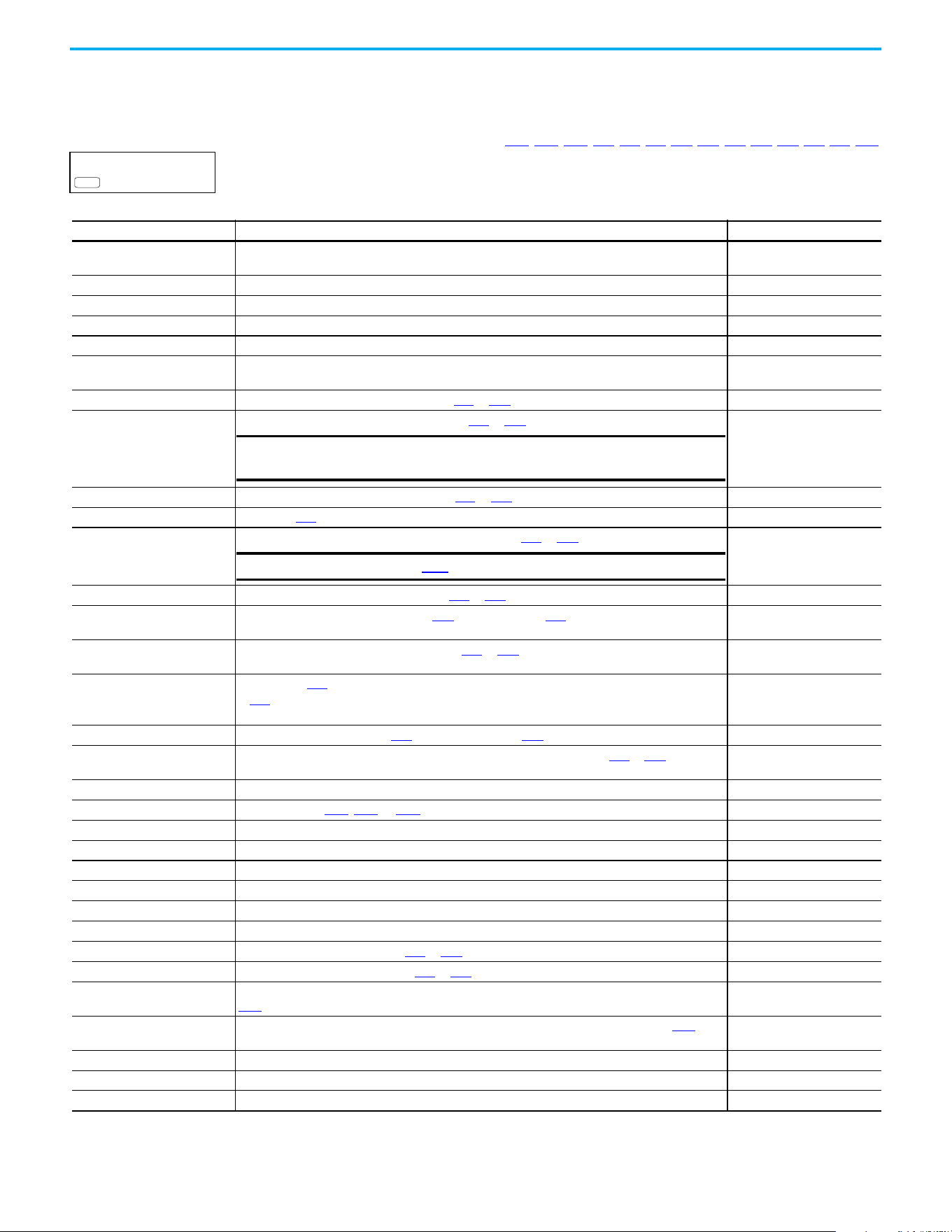
Rockwell Automation Publication 520-UM001N-EN-E - July 2024 95
Chapter 3 Programming and Parameters
Terminal Block Group (continued)
Programmable Relay Outputs
t076 [Relay Out1 Sel] Related Parameters: P046, P048, P050, t070, t073, t077, t082, t086, t087, t093, t094, t097, A541, A564
t081 [Relay Out2 Sel]
PowerFlex 525 only
Determines the operation of the programmable output relay.
PF 525
Options Output Relay Changes State When... Hysteresis
0 “Ready/Fault” Relay changes state when power is applied. Indicates that the drive is ready for operation. Relay
returns drive to shelf state when power is removed or a fault occurs.
None
1 “At Frequency” Drive reaches commanded frequency. 0.5 Hz above; 1.0 Hz below
2 “MotorRunning” Motor is receiving power from the drive. None
3 “Reverse” Drive is commanded to run in reverse direction. None
4 “Motor Overld” Motor overload condition exists. 100 ms time delay on or off
5 “Ramp Reg” Ramp regulator is modifying the programmed accel/ decel times to avoid an overcurrent or
overvoltage fault from occurring.
100 ms time delay on or off
6 “Above Freq” Drive exceeds the frequency (Hz) value set in t077
or t082 [Relay Outx Level]. 100 ms time delay on or off
7 “Above Cur” Drive exceeds the current (% Amps) value set in t077
or t082 [Relay Outx Level].
100 ms time delay on or off
8 “Above DCVolt” Drive exceeds the DC bus voltage value set in t077
or t082 [Relay Outx Level]. 100 ms time delay on or off
9 “Retries Exst” Value set in A541
[Auto Rstrt Tries] is exceeded. None
10 “Above Anlg V” Analog input voltage (0…10V input) exceeds the value set in t077
or t082 [Relay Outx Level].
100 ms time delay on or off
11 “Above PF Ang” Power Factor angle exceeds the value set in t077
or t082 [Relay Outx Level]. 100 ms time delay on or off
12 “Anlg In Loss” Analog input loss has occurred. Program t094
[Anlg In V Loss] or t097 [Anlg In mA Loss] for desired
action when input loss occurs.
On, 2 mA / ±1V
Off, 3 mA / ±1.5V
13 “ParamControl” Output is directly controlled by the state of the t077
or t082 [Relay Outx Level]. A value of 0 causes the
output to turn off. A value of 1 or greater in this parameter causes the output to turn on.
None
14 “NonRec Fault” • Value set in A541 [Auto Rstrt Tries] is exceeded or
• A541
[Auto Rstrt Tries] is not enabled or
• A non-resettable fault has occurred.
None
15 “EM Brk Cntrl” EM Brake is energized. Program t087
[EM Brk On Delay] and t086 [EM Brk Off Delay] for desired action. None
16 “Thermal OL” Relay energizes when thermal Motor overload counter is above the value set in t077
or t082 [Relay Outx
Level]. It also energizes if the drive is within 5 °C (9 °F) of the drive overheat trip point.
None
17 “Amb OverTemp” Relay energizes when control module over temperature occurs. None
18 “Local Active Active when drive P046
, P048, or P050 [Start Source x] is in local keypad control. None
19 “Comm Loss” Active when communication is lost from any comm source with reference or control. None
20 “Logic In 1”
(1)
(1) Setting is specific to PowerFlex 525 drives only.
An input is programmed as “Logic Input 1” and is active. None
21 “Logic In 2”
(1)
An input is programmed as “Logic Input 2” and is active. None
22 “Logic 1 & 2”
(1)
Both Logic inputs are programmed and active. None
23 “Logic 1 or 2”
(1)
One or both Logic inputs are programmed and one or both is active. None
24 “StpLogic Out”
(1)
Drive enters StepLogic step with Command Word set to enable Logic output. None
25 “Timer Out” Timer has reached the value set in t077
or t082 [Relay Outx Level] or not timing. None
26 “Counter Out” Counter has reached the value set in t077
or t082 [Relay Outx Level] or not counting. None
27 “At Position”
(1)
Drive is in Positioning mode and has reached the commanded position. Tolerance is adjusted with
A564 [Encoder Pos Tol].
—
28 “At Home”
(1)
Drive is in Positioning mode and has reached the home position. Tolerance is adjusted with A564
[Encoder Pos Tol].
—
29 “Safe-Off”
(1)
Both safe-off inputs are active. —
30 “SafeTqPermit”
(1)(2)
(2) Setting is available in FRN 5.xxx and later.
Both safe-off inputs are inactive (closed). —
31 “AutoRst Ctdn”
(1)(2)
Drive is counting down to an automatic restart. —
IMPORTANT
Value for t077 or t082 [Relay Outx Level] must be entered in
percent of drive rated output current.
IMPORTANT
Do not use if t093 [10V Bipolar Enbl] is set to 1 “Bi-Polar In”.
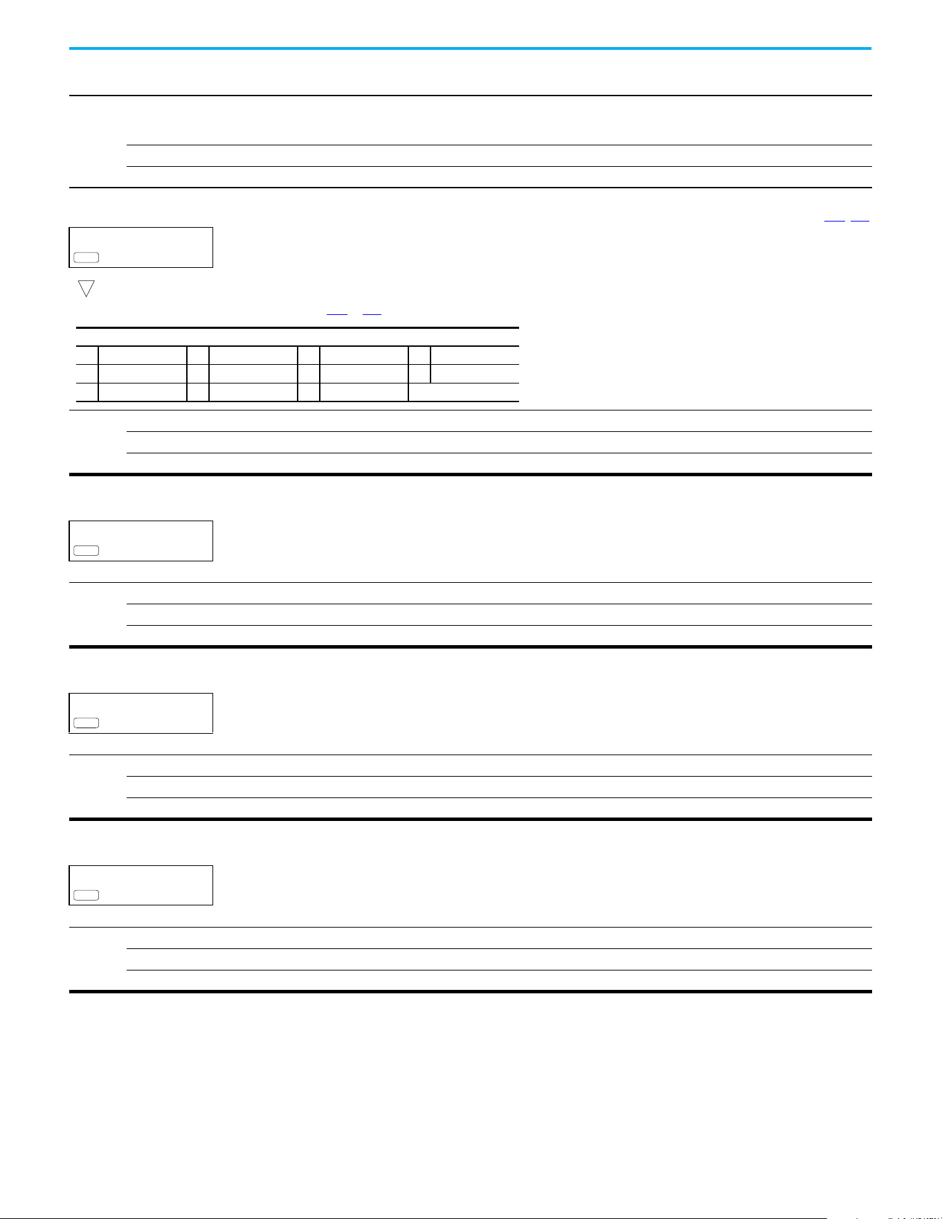
96 Rockwell Automation Publication 520-UM001N-EN-E - July 2024
Chapter 3 Programming and Parameters
Values
Default:
Relay Out1 Sel:
Relay Out2 Sel:
0
2
Min/Max: 0/31
Display: 1
Programmable Relay Outputs (Continued)
t077 [Relay Out1 Level] Related Parameters: t076, t081
t082 [Relay Out2 Level]
PowerFlex 525 only
32-bit parameter
Determines the on/off point for the output relay when t076 or t081 [Relay Outx Sel] is set to the values shown below.
Values
Default: 0.0
Min/Max: 0.0/9999.0
Display: 0.1
PF 525
32
Min/Max Value Range Based On [Relay Outx Sel] Setting
6: 0…500 Hz 10: 0…100% 16: 0.1…9999 s 20: 0/1
7: 0…180% 11: 0/1 17: 1…9999 counts 26: 0…150%
8: 0…815V 13: 0…800 18: 0…180 °C —
t078 [RelayOut1 LevelF]
t083 [RelayOut2 LevelF]
PowerFlex 525 only
Determines the on/off point (fractional portion) for the output relay.
Values
Default: Read Only
Min/Max: 0.0/0.9 s
Display: 0.1 s
PF 525
t079 [Relay 1 On Time]
t084 [Relay 2 On Time]
PowerFlex 525 only
Sets the delay time before Relay energizes after required condition is met.
Values
Default: 0.0 s
Min/Max: 0.0/600.0 s
Display: 0.1 s
PF 525
t080 [Relay 1 Off Time]
t085 [Relay 2 Off Time]
PowerFlex 525 only
Sets the delay time before Relay de-energizes after required condition ceases.
Values
Default: 0.0 s
Min/Max: 0.0/600.0 s
Display: 0.1 s
PF 525
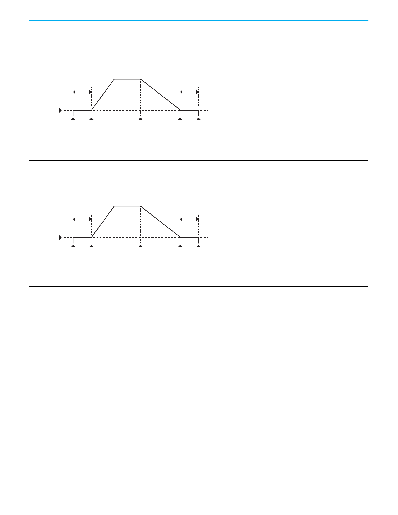
Rockwell Automation Publication 520-UM001N-EN-E - July 2024 97
Chapter 3 Programming and Parameters
Terminal Block Group (continued)
t086 [EM Brk Off Delay] Related Parameters: P045
Sets the time that the drive remains at minimum frequency before ramping up to the commanded frequency (and engaging the brake coil relay) if Electromechanical (EM)
Brake Control Mode is enabled with P045 [Stop Mode].
Values
Default: 2.00 s
Min/Max: 0.00/10.00 s
Display: 0.01 s
Frequency
Time
[Minimum Freq]
[EM Brk O Delay]
[EM Brk On Delay]
Stop
commanded
Start
commanded
EM Brk
de-energized (On)
Drive stopsEM Brk
energized (O)
Ramp accel
Ramp decel
t087 [EM Brk On Delay] Related Parameters: P045
Sets the time that the drive remains at minimum frequency (after releasing the brake coil relay) before stopping if EM Brake Control Mode is enabled with P045 [Stop
Mode].
Values
Default: 2.00 s
Min/Max: 0.00/10.00 s
Display: 0.01 s
Frequency
Time
[Minimum Freq]
[EM Brk O Delay]
[EM Brk On Delay]
Stop
commanded
Start
commanded
EM Brk
de-energized (On)
Drive stopsEM Brk
energized (O)
Ramp accel
Ramp decel
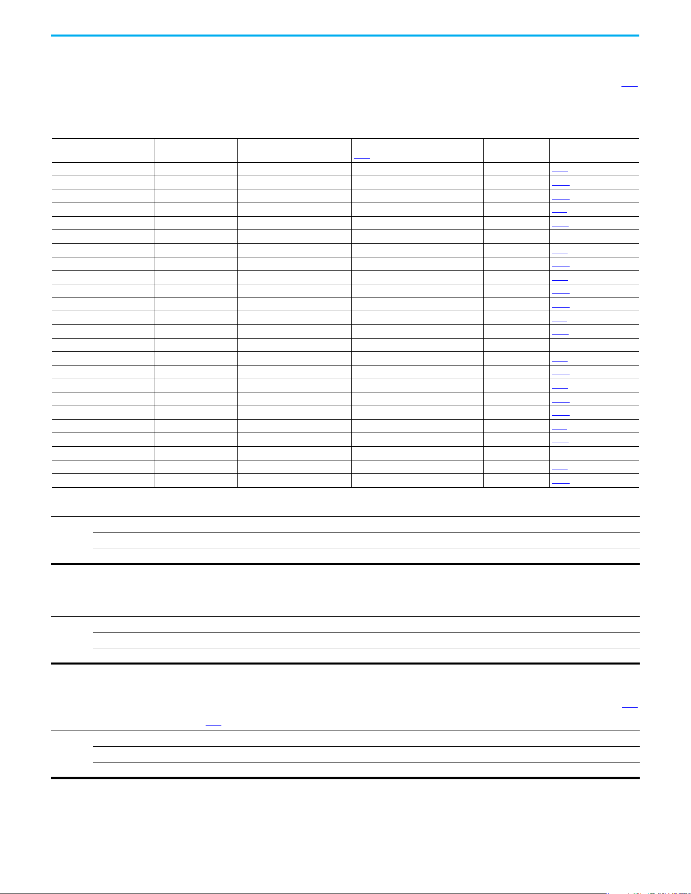
98 Rockwell Automation Publication 520-UM001N-EN-E - July 2024
Chapter 3 Programming and Parameters
Terminal Block Group (continued)
t088 [Analog Out Sel] Related Parameters: t090
The 0…10V, 0…20 mA or 4…0 mA analog output can be used to provide a signal proportional to several drive conditions. This parameter also selects which analog
calibration parameters to use.
(1)
(1) Parameter is also available in PowerFlex 523 FRN 3.xxx and later. PowerFlex 523 Series B drive is required.
Values
Default: 0
Min/Max: 0/23
Display: 1
Options Output Range Minimum Output Value
Maximum Output Value =
t089 [Analog Out High]
Filter
(1)
(1) Filter A is a single pole digital filter with a 162 ms time constant. Given a 0…100% step input from a steady state, the output of Filter A takes 500 ms to get to 95% of maximum, 810 ms to
get to 99%, and 910 ms to get to 100%.
Related Parameter
0 “OutFreq 0-10” 0-10V 0V = 0 Hz [Maximum Freq] None b001
1 “OutCurr 0-10” 0-10V 0V = 0 A 200% Drive Rated Current Filter A b003
2 “OutVolt 0-10” 0-10V 0V = 0V 120% Drive Rated Output Volts None b004
3 “OutPowr 0-10” 0-10V 0V = 0 kW 200% Drive Rated Power Filter A b017
4 “OutTorq 0-10” 0-10V 0V = 0 A 200% Drive Rated Current Filter A d382
5 “TstData 0-10” 0-10V 0V = 0000 65535 (Hex FFFF) None —
6 “Setpnt 0-10” 0-10V 0V = 0% 100.0% Setpoint setting None t090
7 “DCVolt 0-10” 0-10V 0V = 0V 100.0% of trip value None b005
8 “OutFreq 0-20” 0-20 mA 0 mA = 0 Hz [Maximum Freq] None b001
9 “OutCurr 0-20” 0-20 mA 0 mA = 0 A 200% Drive Rated Current Filter A b003
10 “OutVolt 0-20” 0-20 mA 0 mA = 0V 120% Drive Rated Output Volts None b004
11 “OutPowr 0-20” 0-20 mA 0 mA = 0 kW 200% Drive Rated Power Filter A b017
12 “OutTorq 0-20” 0-20 mA 0 mA = 0 A 200% Drive Rated Current Filter A d382
13 “TstData 0-20” 0-20 mA 0 mA = 0000 65535 (Hex FFFF) None —
14 “Setpnt 0-20” 0-20 mA 0 mA = 0% 100.0% Setpoint setting None t090
15 “DCVolt 0-20” 0-20 mA 0 mA = 0V 100.0% of trip value None b005
16 “OutFreq 4-20” 4-20 mA 4 mA = 0 Hz [Maximum Freq] None b001
17 “OutCurr 4-20” 4-20 mA 4 mA = 0 A 200% Drive Rated Current Filter A b003
18 “OutVolt 4-20” 4-20 mA 4 mA = 0V 120% Drive Rated Output Volts None b004
19 “OutPowr 4-20” 4-20 mA 4 mA = 0 kW 200% Drive Rated Power Filter A b017
20 “OutTorq 4-20” 4-20 mA 4 mA = 0 A 200% Drive Rated Current Filter A d382
21 “TstData 4-20” 4-20 mA 4 mA = 0000 65535 (Hex FFFF) None —
22 “Setpnt 4-20” 4-20 mA 4 mA = 0% 100.0% Setpoint setting None t090
23 “DCVolt 4-20” 4-20 mA 4 mA = 0V 100.0% of trip value None b005
t089 [Analog Out High]
Scales the maximum output value (V or mA) when the source setting is at maximum.
(1)
Values
Default: 100%
Min/Max: 0/800%
Display: 1%
(1) Parameter is also available in PowerFlex 523 FRN 3.xxx and later. PowerFlex 523 Series B drive is required.
t090 [Anlg Out Setpt] Related Parameters: t088
Sets the percentage of output desired when t088 [Analog Out Sel] is set to 6, 14 or 22 “Analog Setpoint”.
(1)
Values
Default: 0.0%
Min/Max: 0.0/100.0%
Display: 0.1%
(1) Parameter is also available in PowerFlex 523 FRN 3.xxx and later. PowerFlex 523 Series B drive is required.
Rockwell Automation Publication 520-UM001N-EN-E - July 2024 99
Chapter 3 Programming and Parameters
Terminal Block Group (continued)
t091 [Anlg In 0-10V Lo] Related Parameters: P043, t092, t093
Stop drive before changing this parameter.
Sets the percentage (based on 10V) of input voltage applied to the 0…10V analog input that is used to represent P043 [Minimum Freq].
Analog inversion can be accomplished by setting this value larger than t092 [Anlg In 0-10V Hi].
If t093 [10V Bipolar Enbl] is set to 1 “Bi-Polar In”, this parameter is ignored.
Values
Default: 0.0%
Min/Max: 0.0/200.0%
Display: 0.1%
t092 [Anlg In 0-10V Hi] Related Parameters: P044, t091, t093
Stop drive before changing this parameter.
Sets the percentage (based on 10V) of input voltage applied to the 0…10V analog input that is used to represent P044 [Maximum Freq].
Analog inversion can be accomplished by setting this value smaller than t091 [Anlg In 0-10V Lo].
If t093 [10V Bipolar Enbl] is set to 1 “Bi-Polar In”, the same value applies to positive and negative voltage.
Values
Default: 100.0%
Min/Max: 0.0/200.0%
Display: 0.1%
t093 [10V Bipolar Enbl] Related Parameters: t091, t092
PowerFlex 525 only
Enables/disables bi-polar control. In bi-polar mode direction is commanded by the polarity of the voltage.
If bi-polar control is enabled, P043 [Minimum Freq] and t091 [Anlg In 0-10V Lo] are ignored.
Options
0 “Uni-Polar In” (Default) 0…10V only
1 “Bi-Polar In” ±10V
PF 525
t094 [Anlg In V Loss] Related Parameters: P043, P044, A426, A427
Sets the response to a loss of input. When the 0…10V input (or –10…+10V) is used for any reference, any input less than 1V is reported as a signal loss. Input must exceed
1.5V for the signal loss condition to end.
If enabled, this function affects any input that is being used as a speed reference, PID reference or PID setpoint in the drive.
Options
0 “Disabled” (Default)
1 “Fault (F29)”
2“Stop”
3“Zero Ref”
4“Min Freq Ref”
5“Max Freq Ref”
6“Key Freq Ref”
7“MOP Freq Ref”
8 “Continu Last”
t095 [Anlg In4-20mA Lo] Related Parameters: P043, t096
Stop drive before changing this parameter.
Sets the percentage (based on 4…20 mA) of input current applied to the 4…20 mA analog input that is used to represent P043 [Minimum Freq].
Analog inversion can be accomplished by setting this value larger than t096 [Anlg In4-20mA Hi].
Values
Default: 0.0%
Min/Max: 0.0/200.0%
Display: 0.1%
100 Rockwell Automation Publication 520-UM001N-EN-E - July 2024
Chapter 3 Programming and Parameters
Terminal Block Group (continued)
t096 [Anlg In4-20mA Hi] Related Parameters: P044, t095
Stop drive before changing this parameter.
Sets the percentage (based on 4…20 mA) of input current applied to the 4…20 mA analog input that is used to represent P044 [Maximum Freq].
Analog inversion can be accomplished by setting this value smaller than t095 [Anlg In4-20mA Lo].
Values
Default: 100.0%
Min/Max: 0.0/200.0%
Display: 0.1%
t097 [Anlg In mA Loss] Related Parameters: P043, P044, A426, A427
Sets the response to a loss of input. When the 4…20 mA input is used for any reference, any input less than 2 mA is reported as a signal loss. Input must exceed 3 mA for
the signal loss condition to end.
If enabled, this function affects any input that is being used as a speed reference or PID reference or PID setpoint in the drive.
Options
0 “Disabled” (Default)
1 “Fault (F29)”
2“Stop”
3“Zero Ref”
4“Min Freq Ref”
5“Max Freq Ref”
6“Key Freq Ref”
7“MOP Freq Ref”
8 “Continu Last”
t099 [Analog In Filter] Related Parameters: t091, t092, t095, t096
Sets the level of additional filtering of the analog input signals. The higher number increases filtering and decreases bandwidth. Each setting doubles the applied filtering
(1 = 2x filter, 2= 4x filter, and so on). No additional filtering is applied when set to “0”.
Values
Default: 0
Min/Max: 0 /14
Display: 1
t098 [Anlg Loss Delay] Related Parameters: t094, t097
Sets the length of time after power-up during which the drive detects no analog signal loss.
Response to an analog signal loss is set in t094 or t097 [Analog In x Loss].
Values
Default: 0.0 s
Min/Max: 0.0 /20.0 s
Display: 0.1 s
t100 [Sleep-Wake Sel] Related Parameters: t101, t102, t103
Drive “sleeps” if the appropriate analog input drops below the set t101 [Sleep Level] for the time set in t102 [Sleep Time] and the drive is running. When entering sleep mode
the drive ramps to zero and the run indicator on the keypad display flashes to indicate that the drive is in “sleep” mode.
When the appropriate analog input rises above the set [Wake Level], the drive “wakes” and ramps to the commanded frequency.
Inversion can be accomplished by setting [Sleep Level] to a higher setting than t103 [Wake Level].
Options
0 “Disabled” (Default)
1 “0-10V Input” Sleep enabled from 0…10V Analog Input 1
2 “4-20mA Input” Sleep enabled from 4…20 mA Analog Input 2
3 “Command Freq” Sleep enabled based on drive commanded frequency
ATTENTION: Enabling the Sleep-Wake function can cause unexpected machine operation during the Wake mode.
Equipment damage and/or personal injury can result if this parameter is used in an inappropriate application. In addition,
all applicable local, national, and international codes, standards, regulations or industry guidelines must be considered.

Rockwell Automation Publication 520-UM001N-EN-E - July 2024 101
Chapter 3 Programming and Parameters
Terminal Block Group (continued)
t101 [Sleep Level]
Sets the analog input level that the drive must reach to enter sleep mode.
Values
Default: 10.0%
Min/Max: 0.0/100.0%
Display: 0.1%
t102 [Sleep Time]
Sets the analog input time that the drive must stay below to enter sleep mode.
Values
Default: 0.0 s
Min/Max: 0.0/600.0 s
Display: 0.1 s
t103 [Wake Level]
Sets the analog input level that the drive must reach to wake from sleep mode.
Values
Default: 15.0%
Min/Max: 0.0/100.0%
Display: 0.1%
t104 [Wake Time]
Sets the analog input time that the drive must stay above to wake from sleep mode.
Values
Default: 0.0 s
Min/Max: 0.0/600.0 s
Display: 0.1 s
t105 [Safety Open En]
PowerFlex 525 only
Sets the action when both safety inputs (Safety 1 and Safety 2) are disabled (de-energized – no power is applied).
Options
0 “FaultEnable” (Default)
1“FaultDisable”
PF 525
t106 [SafetyFlt RstCfg]
PowerFlex 525 only
(With FRN 5.xxx and later.)
Sets the method of resetting fault F111 “Safety Hardware” either with a power cycle or fault clear operation.
Options
0 “PwrCycleRset” (Default) Reset fault F111 using power cycle.
1 “FltClr Reset” Reset fault F111 using fault clear mechanism without power cycle.
PF 525

102 Rockwell Automation Publication 520-UM001N-EN-E - July 2024
Chapter 3 Programming and Parameters
Communications Group
C121 [Comm Write Mode]
Saves parameter values in active drive memory (RAM) or in drive nonvolatile memory (EEPROM).
Options
0“Save” (Default)
1 “RAM only”
IMPORTANT
Parameter values set prior to setting 1 “RAM only” are saved in RAM.
ATTENTION: If Automatic Drive Configuration (ADC) is used, this parameter must remain at its default value of 0
“Save”.
C122 [Cmd Stat Select]
PowerFlex 525 only
Selects velocity-specific or position/fibers-specific Command and Status Word bit definitions for use over a communication network. See Writing (06) Logic Command
Data on page 207 for more information. This parameter cannot be changed when an I/O connection is established through the communication adapter or the drive’s
embedded EtherNet/IP port.
Options
0 “Velocity” (Default)
1“Position”
PF 525
C123 [RS485 Data Rate]
Sets the communications rate (bits/second) for the RS-485 port. A reset or power cycle is required after selection is made.
Options
0“1200”
1“2400”
2“4800”
3“9600” (Default)
4“19,200”
5“38,400”
C124 [RS485 Node Addr]
Sets the Modbus drive node number (address) for the RS-485 port if using a network connection. A reset or power cycle is required after selection is made.
Values
Default: 100
Min/Max: 1/247
Display: 1
C125 [Comm Loss Action] Related Parameters: P045
Sets the drive's response to a loss of connection or excessive communication errors on the RS-485 port.
Options
0 “Fault” (Default)
1 “Coast Stop” Stops drive using “Coast to stop”.
2 “Stop” Stops drive using P045
[Stop Mode] setting.
3 “Continu Last” Drive continues operating at communication commanded speed that is saved in RAM.
C126 [Comm Loss Time] Related Parameters: C125
Sets the time that the drive remains in communication loss with the RS-485 port before taking the action specified in C125 [Comm Loss Action]. See Appendix C for more
information.
Values
Default: 5.0 s
Min/Max: 0.1/60.0 s
Display: 0.1 s
IMPORTANT
This setting is effective only if I/O that controls the drive is transmitted through the RS-485 port.

Rockwell Automation Publication 520-UM001N-EN-E - July 2024 103
Chapter 3 Programming and Parameters
Communications Group (continued)
C127 [RS485 Format]
Determines the details that are related to the specific Modbus protocol used by the drive. A reset or power cycle is required after selection is made.
Options
0 “RTU 8-N-1” (Default)
1 “RTU 8-E-1”
2 “RTU 8-O-1”
3 “RTU 8-N-2”
4 “RTU 8-E-2”
5 “RTU 8-O-2”
C128 [EN Addr Sel] Related Parameters: C129…C132, C133…C136, C137…C140
PowerFlex 525 only
Enables the IP address, subnet mask, and gateway address to be set with a BOOTP server. Identifies the connections that would be attempted on a reset or power cycle.
A reset or power cycle is required after selection is made.
Options
1 “Parameters”
2 “BOOTP” (Default)
PF 525
C129 [EN IP Addr Cfg 1] Related Parameters: C128
C130 [EN IP Addr Cfg 2]
C131 [EN IP Addr Cfg 3]
C132 [EN IP Addr Cfg 4]
PowerFlex 525 only
Sets the bytes in the IP address. A reset or power cycle is required after selection is made.
Values
Default: 0
Min/Max: 0/255
Display: 1
PF 525
192.168.1.62
[EN IP Addr Cfg 1]
[EN IP Addr Cfg 2]
[EN IP Addr Cfg 3]
[EN IP Addr Cfg 4]
IMPORTANT
C128 [EN Addr Sel] must be set to 1 “Parameters”.

104 Rockwell Automation Publication 520-UM001N-EN-E - July 2024
Chapter 3 Programming and Parameters
Communications Group (continued)
C133 [EN Subnet Cfg 1] Related Parameters: C128
C134 [EN Subnet Cfg 2]
C135 [EN Subnet Cfg 3]
C136 [EN Subnet Cfg 4]
PowerFlex 525 only
Sets the bytes of the subnet mask. A reset or power cycle is required after selection is made.
Values
Default: 0
Min/Max: 0/255
Display: 1
PF 525
255.255.255.0
[EN Subnet Cfg 1]
[EN Subnet Cfg 2]
[EN Subnet Cfg 3]
[EN Subnet Cfg 4]
IMPORTANT
C128 [EN Addr Sel] must be set to 1 “Parameters”.
C137 [EN Gateway Cfg 1] Related Parameters: C128
C138 [EN Gateway Cfg 2]
C139 [EN Gateway Cfg 3]
C140 [EN Gateway Cfg 4]
PowerFlex 525 only
Sets the bytes of the gateway address. A reset or power cycle is required after selection is made.
Values
Default: 0
Min/Max: 0/255
Display: 1
PF 525
192.168.1.1
[EN Gateway Cfg 1]
[EN Gateway Cfg 2]
[EN Gateway Cfg 3]
[EN Gateway Cfg 4]
IMPORTANT
C128 [EN Addr Sel] must be set to 1 “Parameters”.
C141 [EN Rate Cfg]
PowerFlex 525 only
Sets the network data rate at which EtherNet/IP communicates. A reset or power cycle is required after selection is made.
Options
0 “Auto detect” (Default)
1“10Mbps Full”
2 “10Mbps Half”
3 “100Mbps Full”
4“100Mbps Half”
PF 525
Rockwell Automation Publication 520-UM001N-EN-E - July 2024 105
Chapter 3 Programming and Parameters
Communications Group (continued)
C143 [EN Comm Flt Actn] Related Parameters: P045, C145, C146, C147…C150
PowerFlex 525 only
Sets the action that the EtherNet/IP interface and drive takes if the EtherNet/IP interface detects that Ethernet communications have been disrupted.
Options
0“Fault” (Default)
1 “Stop” Drive stops per P045 [Stop Mode] setting.
2 “Zero Data” Note: The Reference and Datalink values that are transmitted to the drive are set to “0”.
3 “Hold Last” Note: The Logic Command, Reference, and Datalink values that are transmitted to the drive are held at their last value.
4 “Send Flt Cfg” Note: The Logic Command, Reference, and Datalink values are transmitted to the drive as configured in C145, C146, and
C147…C150.
PF 525
IMPORTANT
This setting is effective only if I/O that controls the drive is transmitted through the EtherNet/IP interface.
ATTENTION: Risk of injury or equipment damage exists. Parameter C143 [EN Comm Flt Actn] lets you determine the
action of the EtherNet/IP interface and connected drive if communications are disrupted. By default, this parameter
faults the drive. You can set this parameter so that the drive continues to run. Precautions should be taken to ensure
that the setting of this parameter does not create a risk of injury or equipment damage. When commissioning the
drive, verify that your system responds correctly to various situations (for example, a disconnected drive).
C144 [EN Idle Flt Actn] Related Parameters: P045, C145, C146, C147…C150
PowerFlex 525 only
Sets the action that the EtherNet/IP interface and drive takes if the EtherNet/IP interface detects that the scanner is idle because the controller was switched to program
mode.
Options
0“Fault” (Default)
1 “Stop” Drive stops per P045 [Stop Mode] setting.
2 “Zero Data” The Reference and Datalink values that are transmitted to the drive are set to “0”.
3 “Hold Last” The Logic Command, Reference, and Datalink values that are transmitted to the drive are held at their last value.
4 “Send Flt Cfg” The Logic Command, Reference, and Datalink values are transmitted to the drive as configured in C145, C146, and
C147…C150.
PF 525
ATTENTION: Risk of injury or equipment damage exists. Parameter C144 [EN Idle Flt Actn] lets you determine the action
of the EtherNet/IP interface and connected drive if the scanner is idle. By default, this parameter faults the drive. you can
set this parameter so that the drive continues to run. Precautions should be taken to ensure that the setting of this
parameter does not create a risk of injury or equipment damage. When commissioning the drive, verify that your system
responds correctly to various situations (for example, a disconnected drive).
C145 [EN Flt Cfg Logic] Related Parameters: C143, C144
32-bit parameter
PowerFlex 525 only
Sets the Logic Command data that is sent to the drive if any of the following is true:
– C143 [EN Comm Flt Actn] is set to 4 “Send Flt Cfg” and communications are disrupted.
– C144 [EN Idle Flt Actn] is set to 4 “Send Flt Cfg” and the scanner is put into Program or Test mode.
See Writing (06) Logic Command Data on page 207 for more information.
Values
Default: 0000
Min/Max: 0000/FFFF
Display: 0000
32
PF 525

106 Rockwell Automation Publication 520-UM001N-EN-E - July 2024
Chapter 3 Programming and Parameters
Communications Group (continued)
C146 [EN Flt Cfg Ref] Related Parameters: C143, C144
32-bit parameter
PowerFlex 525 only
Sets the Reference data that is sent to the drive if any of the following is true:
– C143 [EN Comm Flt Actn] is set to 4 “Send Flt Cfg” and communications are disrupted.
– C144 [EN Idle Flt Actn] is set to 4 “Send Flt Cfg” and the scanner is put into Program or Test mode.
Values
Default: 0
Min/Max: 0/50000
Display: 1
32
PF 525
C147 [EN Flt Cfg DL 1]
C148 [EN Flt Cfg DL 2]
C149 [EN Flt Cfg DL 3]
C150 [EN Flt Cfg DL 4]
PowerFlex 525 only
Sets the Ethernet Datalink Input data that is sent to the drive if any of the following is true:
– C143 [EN Comm Flt Actn] is set to 4 “Send Flt Cfg” and communications are disrupted.
– C144 [EN Idle Flt Actn] is set to 4 “Send Flt Cfg” and the scanner is put into Program or Test mode.
Values
Default: 0
Min/Max: 0/65535
Display: 1
PF 525
C153 [EN Data In 1]
C154 [EN Data In 2]
C155 [EN Data In 3]
C156 [EN Data In 4]
PowerFlex 525 only
Datalink parameter number whose value is written from the embedded EtherNet/IP data table. This parameter cannot be changed when an I/O connection is established
through the drive’s embedded EtherNet/IP port.
Values
Default: 0
Min/Max: 0/800
Display: 1
PF 525
C157 [EN Data Out 1]
C158 [EN Data Out 2]
C159 [EN Data Out 3]
C160 [EN Data Out 4]
PowerFlex 525 only
Datalink parameter number whose value is read from the embedded EtherNet/IP data table. This parameter cannot be changed when an I/O connection is established
through the drive’s embedded EtherNet/IP port.
Values
Default: 0
Min/Max: 0/800
Display: 1
PF 525
C161 [Opt Data In 1]
C162 [Opt Data In 2]
C163 [Opt Data In 3]
C164 [Opt Data In 4]
Datalink parameter number whose value is written from the High Speed Drive Serial Interface (HSDSI) data table. This parameter cannot be changed when an I/O
connection is established through the communication adapter.
Values
Default: 0
Min/Max: 0/800
Display: 1

Rockwell Automation Publication 520-UM001N-EN-E - July 2024 107
Chapter 3 Programming and Parameters
Communications Group (continued)
C165 [Opt Data Out 1]
C166 [Opt Data Out 2]
C167 [Opt Data Out 3]
C168 [Opt Data Out 4]
Datalink parameter number whose value is read from the HSDSI data table. This parameter cannot be changed when an I/O connection is established through the
communication adapter.
Values
Default: 0
Min/Max: 0/800
Display: 1
C169 [MultiDrv Sel]
Sets the configuration of the drive that is in multi-drive mode. A reset or power cycle is required after selection is made.
Options
0 “Disabled” (Default) No multi-drive master from the internal network option module or embedded Ethernet port. The drive can still function as
a multi-drive slave or as a single drive (no multi-drive used).
1 “Network Opt” Multi-drive is enabled with the internal network option as a multi-drive master. The host drive is “Drive 0” and up to four
slave drives can be daisy chained from its RS-485 port.
2 “EtherNet/IP”
(1)
Multi-drive is enabled with the embedded Ethernet port as the multi-drive master. The host drive is “Drive 0” and up to
four slave drives can be daisy chained from its RS-485 port.
(1) Setting is specific to PowerFlex 525 drives only.
C171 [Drv 1 Addr] Related Parameters: C169
C172 [Drv 2 Addr]
C173 [Drv 3 Addr]
C174 [Drv 4 Addr]
Sets the corresponding node addresses of the daisy chained drives when C169
[MultiDrv Sel] is set to 1 “Network Opt” or 2 “EtherNet/IP”. A reset or power cycle is required
after selection is made.
Values
Default:
Drv 1 Addr:
Drv 2 Addr:
Drv 3 Addr:
Drv 4 Addr:
2
3
4
5
Min/Max: 1/247
Display: 1
C175 [DSI I/O Cfg]
Sets the configuration of the Drives that are active in the multi-drive mode. Identifies the connections that would be attempted on a reset or power cycle. A reset or power
cycle is required after selection is made.
Options
0“Drive 0” (Default)
1“Drive 0-1”
2“Drive 0-2”
3“Drive 0-3”
4“Drive 0-4”
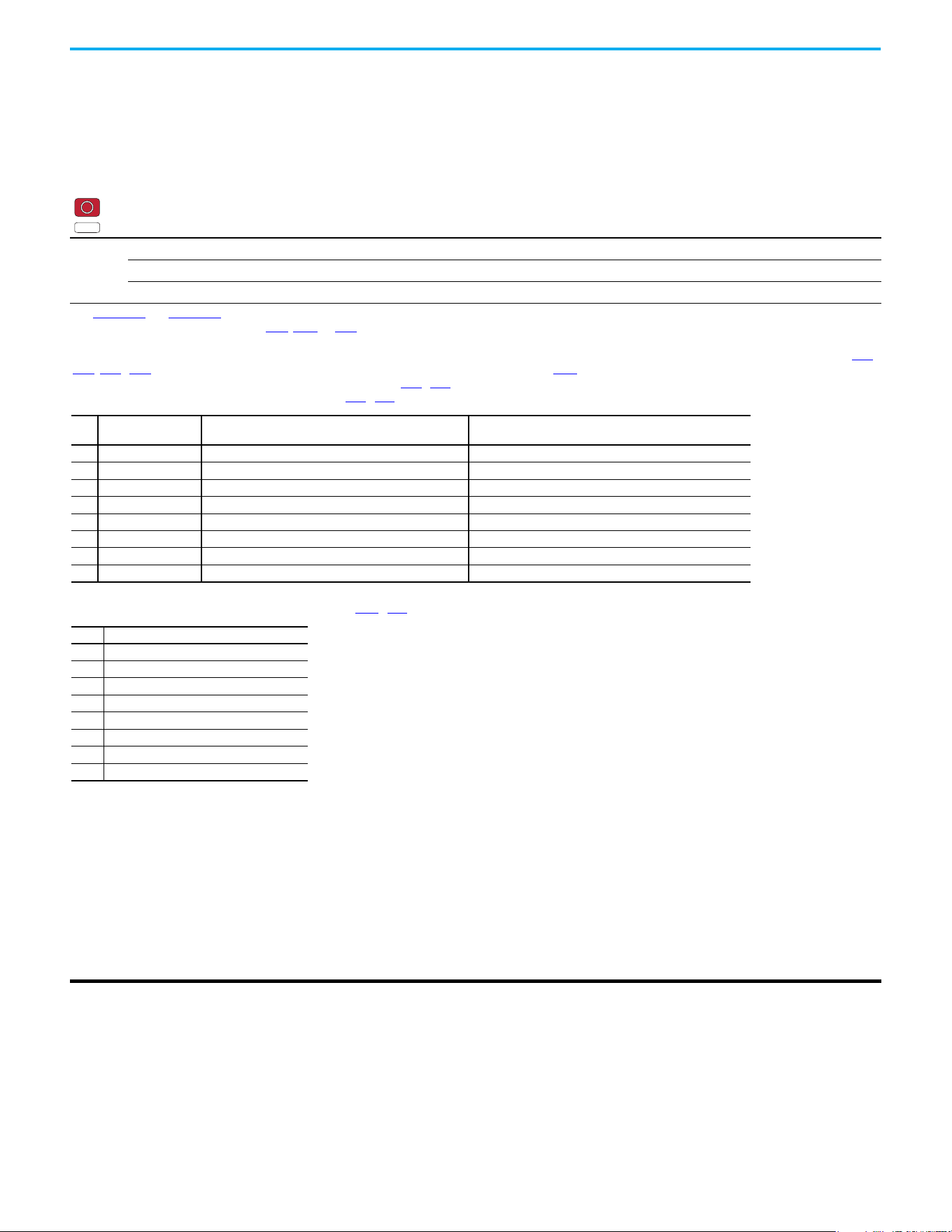
108 Rockwell Automation Publication 520-UM001N-EN-E - July 2024
Chapter 3 Programming and Parameters
Logic Group
StepLogic Inputs
L180 [Stp Logic 0]
L182 [Stp Logic 2]
L184 [Stp Logic 4]
L186 [Stp Logic 6]
L181 [Stp Logic 1]
L183 [Stp Logic 3]
L185 [Stp Logic 5]
L187 [Stp Logic 7]
Stop drive before changing this parameter.
PowerFlex 525 only
Values
Default: 00F1
Min/Max: 0000/FAFF
Display 0001
See Appendix D
and Appendix E for more information on applying StepLogic® function and Position StepLogic application.
Parameters L180…L187 are only active if P047, P049, or P051 [Speed Referencex] is set to 13 “Step Logic” or 16 “Positioning”. These parameters can be used to create a
custom profile of frequency commands. Each “step” can be based on time, status of a Logic input or a combination of time and the status of a Logic input.
Digits 1…4 for each [Stp Logic x] parameter must be programmed according to the desired profile. A Logic input is established by setting a digital input, parameters t062,
t063, t065…t068 [DigIn TermBlk xx] to 24 “Logic In 1” and/or 25 “Logic In 2” or by using Bits 6 and 7 of A560 [Enh Control Word].
A time interval between steps can be programmed using parameters L190…L197 [Stp Logic Time x]. See the table below for related parameters.
The speed for any step is programmed using parameters A410…A417 [Preset Freq x].
The position for any step is programmed using parameters L200
…L214 [Step Units x].
How StepLogic Works
The StepLogic sequence begins with a valid start command. A normal sequence always begins with L180 [Stp Logic 0].
Digit 1: Logic for next step
This digit defines the logic for the next step. When the condition is met the program advances to the next step. Step 0 follows Step 7. Example: Digit 1 is set to 3. When
“Logic In 2” becomes active, the program advances to the next step.
Digit 2: Logic to jump to a different step
For all settings other than F, when the condition is met, the program overrides Digit 0 and jumps to the step defined by Digit 3.
Digit 3: Different step to jump
When the condition for Digit 2 is met, this digit setting determines the next step or to end the program.
Digit 4: Step settings
This digit defines additional characteristics of each step.
Any StepLogic parameter can be programmed to control a relay or opto output, but you cannot control different outputs based on the condition of different StepLogic
commands.
PF 525
Step StepLogic Parameter
Related Preset Frequency Parameter
(Can be activated independent of StepLogic Parameters)
Related StepLogic Time Parameter
(Active when L180...L187 Digit 1 or 2 are set to 1, b, C, d, or E)
0 L180 [Stp Logic 0] A410 [Preset Freq 0] L190 [Stp Logic Time 0]
1 L181 [Stp Logic 1] A411 [Preset Freq 1] L191 [Stp Logic Time 1]
2 L182 [Stp Logic 2] A412 [Preset Freq 2] L192 [Stp Logic Time 2]
3 L183 [Stp Logic 3] A413 [Preset Freq 3] L193 [Stp Logic Time 3]
4 L184 [Stp Logic 4] A414 [Preset Freq 4] L194 [Stp Logic Time 4]
5 L185 [Stp Logic 5] A415 [Preset Freq 5] L195 [Stp Logic Time 5]
6 L186 [Stp Logic 6] A416 [Preset Freq 6] L196 [Stp Logic Time 6]
7 L187 [Stp Logic 7] A417 [Preset Freq 7] L197 [Stp Logic Time 7]
Step StepLogic Position Parameter
0 L200 [Step Units 0] & L201 [Step Units F 0]
1 L202 [Step Units 1] & L203 [Step Units F 1]
2 L204 [Step Units 2] & L205 [Step Units F 2]
3 L206 [Step Units 3] & L207 [Step Units F 3]
4 L208 [Step Units 4] & L209 [Step Units F 4]
5 L210 [Step Units 5] & L211 [Step Units F 5]
6 L212 [Step Units 6] & L213 [Step Units F 6]
7 L214 [Step Units 7] & L215 [Step Units F 7]

Rockwell Automation Publication 520-UM001N-EN-E - July 2024 109
Chapter 3 Programming and Parameters
StepLogic Settings
The logic for each function is determined by the four digits for each StepLogic parameter. The following is a listing of the available settings for each digit. See Appendix D
for more information.
StepLogic Inputs (Continued)
Logic for next step Digit 1
Logic to jump to a different step Digit 2
Different step to jump Digit 3
Step settings Digit 4
Not Used
Velocity Control Settings (Digit 4)
Required
Setting
Accel/Decel
Param. Used
StepLogic
Output State
Commanded
Direction
0 Accel/Decel 1 Off FWD
1 Accel/Decel 1 Off REV
2 Accel/Decel 1 Off No Output
3 Accel/Decel 1 On FWD
4 Accel/Decel 1 On REV
5 Accel/Decel 1 On No Output
6 Accel/Decel 2 Off FWD
7 Accel/Decel 2 Off REV
8 Accel/Decel 2 Off No Output
9 Accel/Decel 2 On FWD
A Accel/Decel 2 On REV
b Accel/Decel 2 On No Output
Positioning Settings (Digit 4)
Required
Setting
Accel/Decel
Param. Used
StepLogic
Output State
Direction
From Home
Type of
Command
0 Accel/Decel 1 Off FWD Absolute
1 Accel/Decel 1 Off FWD Incremental
2 Accel/Decel 1 Off REV Absolute
3 Accel/Decel 1 Off REV Incremental
4 Accel/Decel 1 On FWD Absolute
5 Accel/Decel 1 On FWD Incremental
6 Accel/Decel 1 On REV Absolute
7 Accel/Decel 1 On REV Incremental
8 Accel/Decel 2 Off FWD Absolute
9 Accel/Decel 2 Off FWD Incremental
A Accel/Decel 2 Off REV Absolute
b Accel/Decel 2 Off REV Incremental
C Accel/Decel 2 On FWD Absolute
d Accel/Decel 2 On FWD Incremental
E Accel/Decel 2 On REV Absolute
F Accel/Decel 2 On REV Incremental
Settings (Digit 3)
Setting Description
0Jump to Step 0
1Jump to Step 1
2Jump to Step 2
3Jump to Step 3
4Jump to Step 4
5Jump to Step 5
6Jump to Step 6
7Jump to Step 7
8 End Program (Normal Stop)
9 End Program (Coast to Stop)
A End Program and Fault (F2)
Settings (Digit 2 and 1)
Setting Description
0 Skip Step (Jump Immediately)
1 Step Based on [Stp Logic Time x]
2 Step if “Logic In 1” is Active
3 Step if “Logic In 2” is Active
4 Step if “Logic In 1” is Not Active
5 Step if “Logic In 2” is Not Active
6 Step if either “Logic In 1” or “Logic In 2” is Active
7 Step if both “Logic In 1” and “Logic In 2” are Active
8 Step if neither “Logic In 1” nor “Logic In 2” is Active
9 Step if “Logic In 1” is Active and “Logic In 2” is Not Active
A Step if “Logic In 2” is Active and “Logic In 1” is Not Active
b Step after [Stp Logic Time x] and “Logic In 1” is Active
C Step after [Stp Logic Time x] and “Logic In 2” is Active
d Step after [Stp Logic Time x] and “Logic In 1” is Not Active
E Step after [Stp Logic Time x] and “Logic In 2” is Not Active
F Do Not Step/Ignore Digit 2 Settings

110 Rockwell Automation Publication 520-UM001N-EN-E - July 2024
Chapter 3 Programming and Parameters
Logic Group (continued)
L190 [Stp Logic Time 0]
L192 [Stp Logic Time 2]
L194 [Stp Logic Time 4]
L196 [Stp Logic Time 6]
L191 [Stp Logic Time 1]
L193 [Stp Logic Time 3]
L195 [Stp Logic Time 5]
L197 [Stp Logic Time 7]
PowerFlex 525 only
Sets the time to remain in each step if the corresponding command word is set to “Step based on time”.
Values
Default: 30.0 s
Min/Max: 0.0/999.9 s
Display: 0.1 s
PF 525
L200 [Step Units 0]
L204 [Step Units 2]
L208 [Step Units 4]
L212 [Step Units 6]
L202 [Step Units 1]
L206 [Step Units 3]
L210 [Step Units 5]
L214 [Step Units 7]
32-bit parameter
PowerFlex 525 only
Sets the position in user-defined units that the drive must reach at each step.
Values
Default: 0.00
Min/Max: 0.00/6400.00
Display: 0.01
32
PF 525
L201 [Step Units F 0]
L205 [Step Units F 2]
L209 [Step Units F 4]
L213 [Step Units F 6]
L203 [Step Units F 1]
L207 [Step Units F 3]
L211 [Step Units F 5]
L215 [Step Units F 7]
PowerFlex 525 only
Sets the position in user-defined units (fractional portion) the drive must reach at each step.
Values
Default: Read Only
Min/Max: 0.00/0.99
Display: 0.01
PF 525

Rockwell Automation Publication 520-UM001N-EN-E - July 2024 111
Chapter 3 Programming and Parameters
Advanced Display Group
d360 [Analog In 0-10V] Related Parameters: t091, t092
Displays the 0…10V analog input as a percent of full scale.
Values
Default: Read Only
Min/Max: 0.0/100.0%
Display: 0.1%
d361 [Analog In 4-20mA] Related Parameters: t095, t096
Displays the 4…20 mA analog input as a percent of full scale.
Values
Default: Read Only
Min/Max: 0.0/100.0%
Display: 0.1%
d362 [Elapsed Time-hr] Related Parameters: A555
Displays the total elapsed powered-up time (in hours) since timer reset. The timer stops when it reaches the maximum value.
Values
Default: Read Only
Min/Max: 0/32767 hr
Display: 1 hr
d363 [Elapsed Time-min] Related Parameters: d362, A555
Displays the total elapsed powered-up time (in minutes) since timer reset. Resets to zero when maximum value is reached and increments d362 [Elapsed Time-hr] by one.
Values
Default: Read Only
Min/Max: 0.0/60.0 min
Display: 0.1 min
d364 [Counter Status]
Displays the current value of the counter if enabled.
Values
Default: Read Only
Min/Max: 0/65535
Display: 1
d365 [Timer Status]
32-bit parameter
Displays the current value of the timer if enabled.
Values
Default: Read Only
Min/Max: 0.0/9999.0 s
Display: 0.1 s
32
d366 [Timer StatusF]
Displays the current value of the timer (fractional portion) if enabled.
Values
Default: Read Only
Min/Max: 0.0/0.9 s
Display: 0.1 s

112 Rockwell Automation Publication 520-UM001N-EN-E - July 2024
Chapter 3 Programming and Parameters
Advanced Display Group (continued)
d367 [Drive Type]
Displays the Drive type setting. Used by Rockwell Automation field service personnel (not write accessible by non-Rockwell Automation technical personnel).
Values
Default: Read Only
Min/Max: 0/65535
Display: 1
d368 [Testpoint Data] Related Parameters: A483
Displays the present value of the function that is selected in A483 [Testpoint Sel].
Values
Default: Read Only
Min/Max: 0/FFFF
Display: 1
d369 [Motor OL Level]
Displays the motor overload counter.
Values
Default: Read Only
Min/Max: 0.0/150.0%
Display: 0.1%
d375 [Slip Hz Meter] Related Parameters: P032
Displays the current amount of slip or droop (absolute value) being applied to the motor frequency. Drive applies slip based on the setting for P032 [Motor NP Hertz].
Values
Default: Read Only
Min/Max: 0.0/25.0 Hz
Display: 0.1 Hz
d376 [Speed Feedback]
32-bit parameter
Displays the value of the actual motor speed whether measured by encoder/pulse train feedback or estimated.
Values
Default: Read Only
Min/Max: 0.0/64000.0 rpm
Display: 0.1 rpm
32
d377 [Speed Feedback F]
Displays the value of the actual motor speed (fractional portion) whether measured by encoder/pulse train feedback or estimated.
Values
Default: Read Only
Min/Max: 0.0/0.9 rpm
Display: 0.1 rpm
d378 [Encoder Speed]
32-bit parameter
Provides a monitoring point that reflects the speed that is measured from the feedback device. This shows the encoder or pulse train speed even if not used directly to
control motor speed.
(1)
Values
Default: Read Only
Min/Max: 0.0/64000.0 rpm
Display: 0.1 rpm
(1) Parameter is also available in PowerFlex 523 FRN 3.xxx and later.
32
Rockwell Automation Publication 520-UM001N-EN-E - July 2024 113
Chapter 3 Programming and Parameters
Advanced Display Group (continued)
d379 [Encoder Speed F]
Provides a monitoring point that reflects the speed (fractional portion) measured from the feedback device. This shows the encoder or pulse train speed even if not used
directly to control the motor speed.
Values
Default: Read Only
Min/Max: 0.0/0.9 rpm
Display: 0.1 rpm
d380 [DC Bus Ripple]
Displays the real-time value of the DC bus ripple voltage.
Values
Default: Read Only
Min/Max: 0/410V DC for 230V AC drives; 820V DC for 460V AC drives; 1025V DC for 600V AC drives
Display: 1V DC
d381 [Output Powr Fctr]
Displays the angle in electrical degrees between motor voltage and motor current.
Values
Default: Read Only
Min/Max: 0.0/180.0 deg
Display: 0.1 deg
d382 [Torque Current]
Displays the current value of the motor torque current that is measured by the drive.
Values
Default: Read Only
Min/Max: 0.00/(Drive Rated Amps x 2)
Display: 0.01 A
d383 [PID1 Fdbk Displ]
d385 [PID2 Fdbk Displ]
PowerFlex 525 only
Displays the active PID Feedback value.
Values
Default: Read Only
Min/Max: 0.0/100.0%
Display: 0.1%
PF 525
d384 [PID1 Setpnt Disp]
d386 [PID2 Setpnt Disp]
PowerFlex 525 only
Displays the active PID Setpoint value.
Values
Default: Read Only
Min/Max: 0.0/100.0%
Display: 0.1%
PF 525
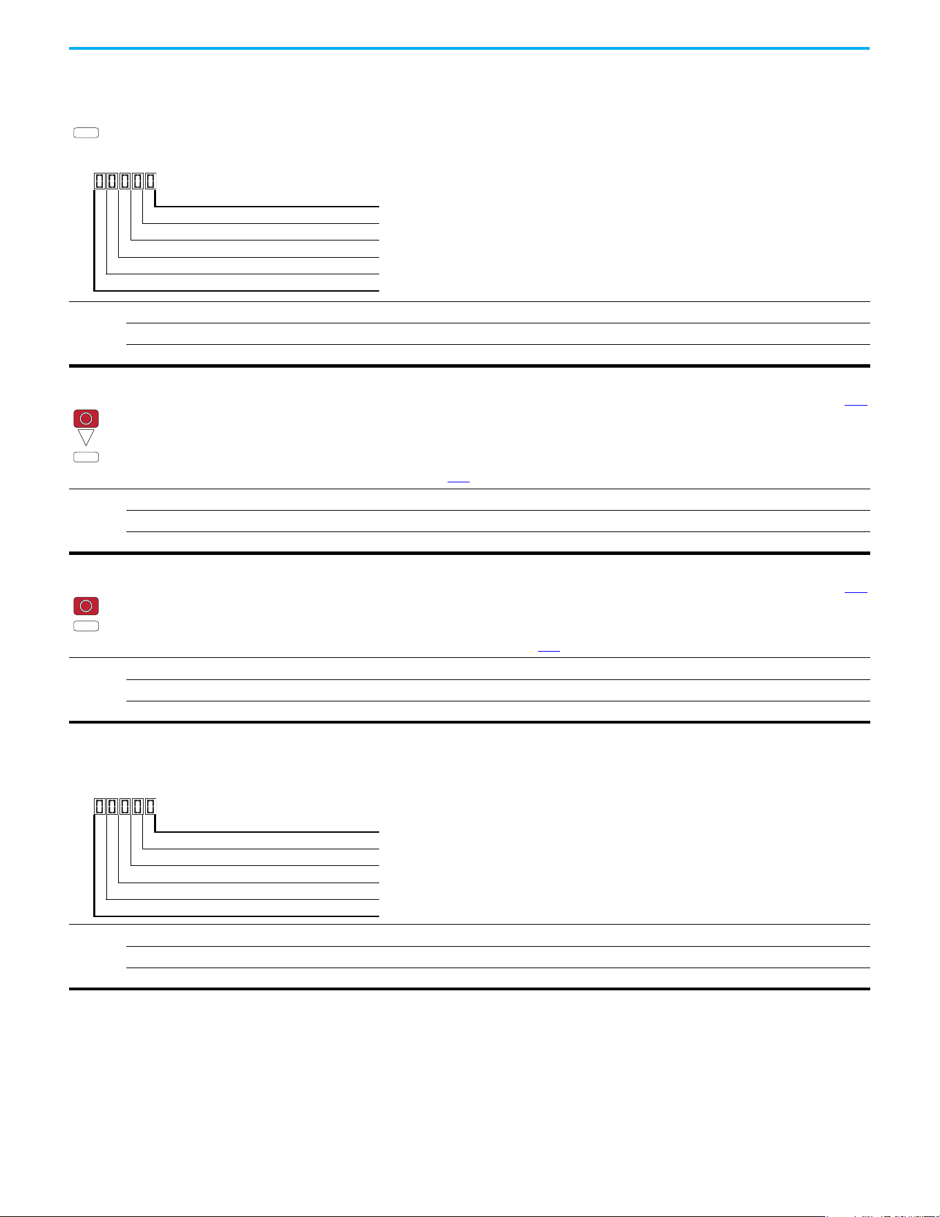
114 Rockwell Automation Publication 520-UM001N-EN-E - July 2024
Chapter 3 Programming and Parameters
Advanced Display Group (continued)
d387 [Position Status]
PowerFlex 525 only
Displays the present operating condition of the drive. When in Positioning mode, Bit 1 indicates positive or negative position in relation to Home.
Values
Default: Read Only
Min/Max: 0000/1111
Display: 0000
PF 525
1 = Condition True, 0 = Condition False
Dir Positive Digit 1
At Position Digit 2
At Home Digit 3
Drive Homed Digit 4
Not Used
d388 [Units Traveled H] Related Parameters: d387
Stop drive before changing this parameter.
32-bit parameter
PowerFlex 525 only
Displays the number of user-defined units traveled from the home position. See d387 [Position Status] for direction of travel.
Values
Default: Read Only
Min/Max: 0/64000
Display: 1
32
PF 525
d389 [Units Traveled L] Related Parameters: d387
Stop drive before changing this parameter.
PowerFlex 525 only
Displays the number of user-defined units (fractional portion) traveled from the home position. See d387 [Position Status] for direction of travel.
Values
Default: Read Only
Min/Max: 0.00/0.99
Display: 0.01
PF 525
d390 [Fiber Status]
Present status of the Fibers features.
Values
Default: Read Only
Min/Max: 0000/1111
Display: 0000
1 = Condition True, 0 = Condition False
Sync Hold Digit 1
Sync Ramp Digit 2
Traverse On Digit 3
Traverse Dec Digit 4
Not Used
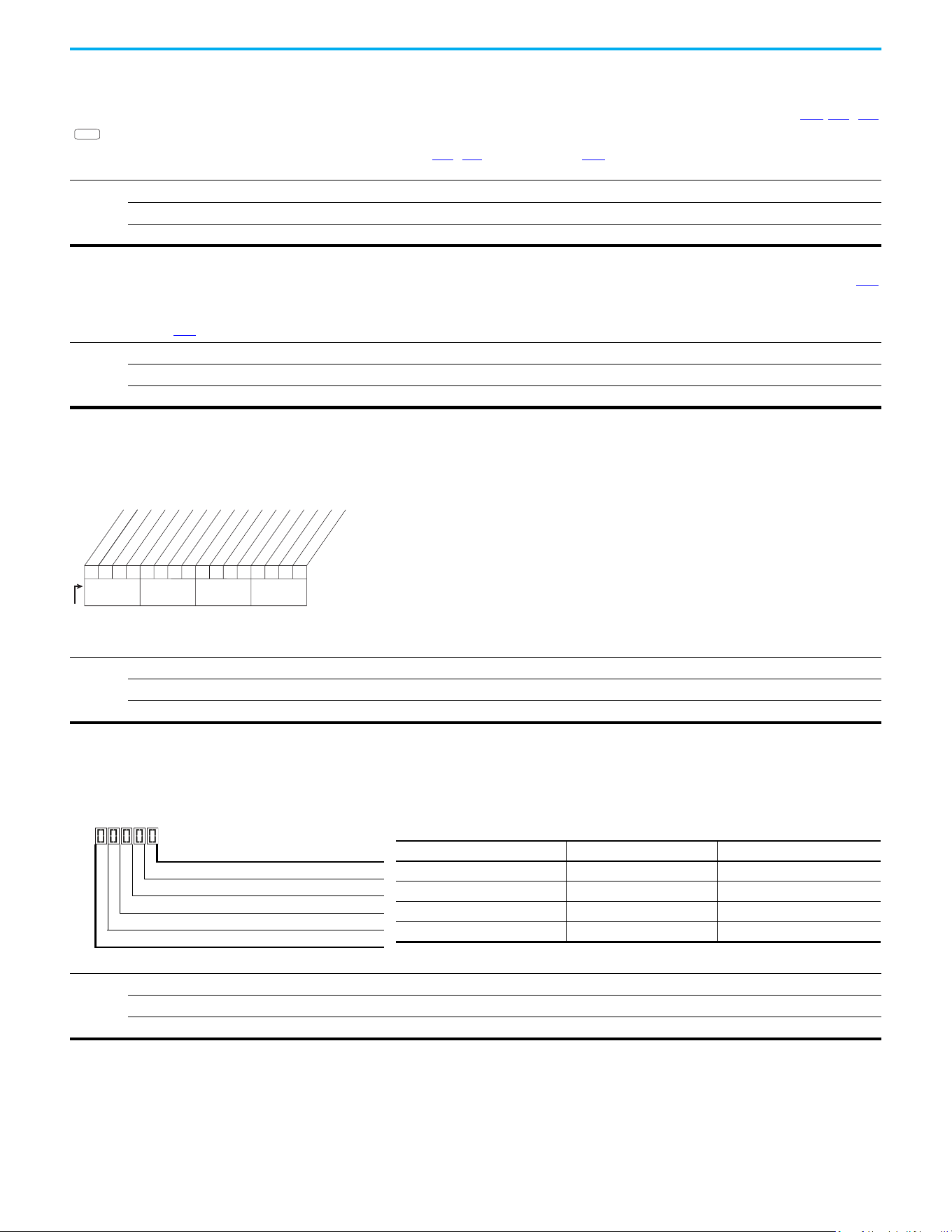
Rockwell Automation Publication 520-UM001N-EN-E - July 2024 115
Chapter 3 Programming and Parameters
Advanced Display Group (continued)
d391 [Stp Logic Status] Related Parameters: P047, L180…L187
PowerFlex 525 only
Displays the current step of the StepLogic profile as defined by parameters L180…L187 [Step Logic x] when P047 [Speed Reference1] is set to 13 “Step Logic” or 16
“Positioning”.
Values
Default: Read Only
Min/Max: 0/8
Display: 1
PF 525
d392 [RdyBit Mode Act] Related Parameters: A574
(With PowerFlex 525 FRN 3.xxx and later.)
(With PowerFlex 523 FRN 3.xxx and later.)
Displays the value of A574 [RdyBit Mode Cfg].
Values
Default: Read Only
Min/Max: 0/1
Display: 1
d393 [Drive Status 2]
(With PowerFlex 525 FRN 5.xxx and later.)
(With PowerFlex 523 FRN 3.xxx and later.)
Displays the present operating condition of the drive.
(1) Bit status is specific to PowerFlex 525 drives only.
Values
Default: Read Only
Min/Max: 0/65535
Display: 1
000000000
x
0000
xx
10 01234567891112131415
1 = Condition True
0 = Condition False
x = Reserved
Bit #
Jogging
Flux Braking
Motor Overld
AutoRst Ctdn
DC Braking
At Freq
Auto Tuning
EM Braking
Curr Limit
Safety S1
(1)
Safety S2
(1)
F111 Status
(1)
SafeTqPermit
(1)
Nibble 1Nibble 2Nibble 3Nibble 4
* Enhanced Control Option Only.
d394 [Dig Out Status]
(With PowerFlex 525 FRN 5.xxx and later.)
(With PowerFlex 523 FRN 3.xxx and later.)
Displays relay output and opto output status.
Values
Default: Read Only
Min/Max: 0/15
Display: 1
Rly1 Status Digit 1
Rly2 Status
(1)
Digit 2
(1) Setting is specific to PowerFlex 525 drives only.
Opto1 Status
(1)
Digit 3
Opto2 Status
(1)
Digit 4
Not Used
Status Bit Value = 0 Bit Value = 1
Relay 1 status (Normally Open) Not activated (Relay 1 open) Activated (Relay 1 closed)
Relay 2 status (Normally Closed) Not activated (Relay 2 closed) Activated (Relay 2 open)
Opto 1 status Not activated Activated
Opto 2 status Not activated Activated
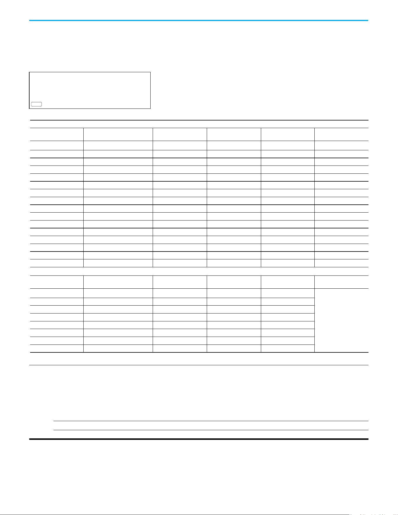
116 Rockwell Automation Publication 520-UM001N-EN-E - July 2024
Chapter 3 Programming and Parameters
Advanced Program Group
A410 [Preset Freq 0]
A412 [Preset Freq 2]
A414 [Preset Freq 4]
A416 [Preset Freq 6]
A411 [Preset Freq 1]
A413 [Preset Freq 3]
A415 [Preset Freq 5]
A417 [Preset Freq 7]
A418 [Preset Freq 8]
A420 [Preset Freq 10]
A422 [Preset Freq 12]
A424 [Preset Freq 14]
PowerFlex 525 only
A419 [Preset Freq 9]
A421 [Preset Freq 11]
A423 [Preset Freq 13]
A425 [Preset Freq 15]
Sets the frequency of the drive outputs to the programmed value when selected.
Values
Defaults:
Preset Freq 0:
Preset Freq 1:
Preset Freq 2:
Preset Freq 3:
Preset Freq 4:
Preset Freq 5:
Preset Freq 6:
Preset Freq 7...15:
0.00 Hz
5.00 Hz
10.00 HZ
20.00 Hz
30.00 Hz
40.00 Hz
50.00 Hz
60.00 Hz
Min/Max: 0.00/500.00 Hz
Display: 0.01 Hz
PF 525
For PowerFlex 525
Default Accel/Decel Used
Preset Input 1
(DigIn TermBlk 05)
Preset Input 2
(DigIn TermBlk 06)
Preset Input 3
(DigIn TermBlk 07)
Preset Input 4
(DigIn TermBlk 08)
Preset Setting 0
(1)
(1) Preset Setting 0 is only available if P047, P049, or P051 [Speed Referencex] is set to 7 “Preset Freq”.
10000
Preset Setting 1 1 1 0 0 0
Preset Setting 2 2 0 1 0 0
Preset Setting 3 2 1 1 0 0
Preset Setting 4 1 0 0 1 0
Preset Setting 5 1 1 0 1 0
Preset Setting 6 2 0 1 1 0
Preset Setting 7 2 1 1 1 0
Preset Setting 8 1 0 0 0 1
Preset Setting 9 1 1 0 0 1
Preset Setting 10 2 0 1 0 1
Preset Setting 11 2 1 1 0 1
Preset Setting 12 1 0 0 1 1
Preset Setting 13 1 1 0 1 1
Preset Setting 14 2 0 1 1 1
Preset Setting 15 2 1 1 1 1
For PowerFlex 523
Default Accel/Decel Used
Preset Input 1
(DigIn TermBlk 05)
Preset Input 2
(DigIn TermBlk 06)
Preset Input 3
(DigIn TermBlk 03)
–
Preset Setting 0
(1)
1000
–
Preset Setting 1 1 1 0 0
Preset Setting 2 2 0 1 0
Preset Setting 3 2 1 1 0
Preset Setting 4 1 0 0 1
Preset Setting 5 1 1 0 1
Preset Setting 6 2 0 1 1
Preset Setting 7 2 1 1 1

Rockwell Automation Publication 520-UM001N-EN-E - July 2024 117
Chapter 3 Programming and Parameters
Advanced Program Group (continued)
A426 [Keypad Freq] Related Parameters: P047, P049, P051
Provides the drive frequency command using the built-in keypad navigation. When P047, P049, or P051 [Speed Referencex] selects 2 “Keypad Freq”, the value set in this
parameter controls the frequency of the drive. The value of this parameter can also be changed when navigating with the keypad by pressing the Up or Down arrow keys.
Values
Default: 60.00 Hz
Min/Max: 0.00/500.00 Hz
Display: 0.01 Hz
A427 [MOP Freq]
Provides the drive frequency command using the built-in Motor Operated Potentiometer (MOP).
Values
Default: 60.00 Hz
Min/Max: 0.00/500.00 Hz
Display: 0.01 Hz
IMPORTANT
Frequency is not written to non-volatile storage until drive is powered-down. If both MOP Up and MOP Down are applied
at the same time, the inputs are ignored and the frequency is unchanged.
A428 [MOP Reset Sel]
Determines if the current MOP reference command is saved on power down.
Options
0 “Zero MOP Ref” Resets the MOP frequency to zero on power down and stop.
1 “Save MOP Ref” (Default)
A429 [MOP Preload]
Determines the operation of the MOP function.
Options
0 “No preload” (Default)
1 “Preload” Bumpless Transfer: whenever MOP mode is selected, the current output value of the speed is loaded.
A430 [MOP Time]
Sets the rate of change of the MOP reference.
Values
Default: 10.0 s
Min/Max: 0.1/600.0 s
Display: 0.1 s
A431 [Jog Frequency] Related Parameters: P044
Sets the output frequency when a jog command is issued.
Values
Default: 10.00 Hz
Min/Max: 0.00/[Maximum Freq]
Display: 0.01 Hz
A432 [Jog Accel/Decel]
Sets the acceleration and deceleration time that is used when in jog mode.
Values
Default: 10.00 s
Min/Max: 0.01/600.00 s
Display: 0.01 s
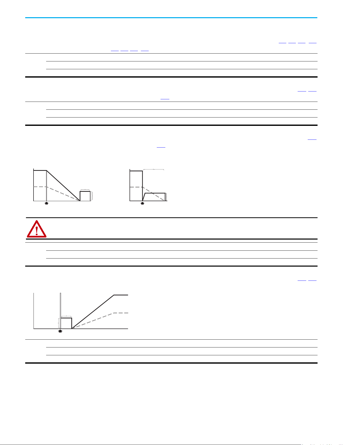
118 Rockwell Automation Publication 520-UM001N-EN-E - July 2024
Chapter 3 Programming and Parameters
Advanced Program Group (continued)
A433 [Purge Frequency] Related Parameters: t062, t063, t065…t068
Provides a fixed frequency command value when t062, t063, t065…t068 [DigIn TermBlk xx] is set to 40 “Purge”.
Values
Default: 5.00 Hz
Min/Max: 0.00/500.00 Hz
Display: 0.01 Hz
A434 [DC Brake Time] Related Parameters: P045, A435
Sets the length of time that DC brake current is “injected” into the motor when P045 [Stop Mode] is set to 10 “PointStp,CF” and 11 “PointStop” or 0 “Ramp,CF” and 4 “Ramp”.
Values
Default: 0.0 s
Min/Max: 0.0/99.9 s
Display: 0.1 s
A435 [DC Brake Level] Related Parameters: P045
Defines the maximum DC brake current, in amps, applied to the motor when P045 [Stop Mode] is set to either 0 “Ramp,CF”, 2 “DC Brake, CF”, 4 “Ramp”, 6 “DC Brake”, 10
“PointStp,CF”, or 11 “PointStop”.
Values
Default: Drive Rated Amps x 0.05
Min/Max: 0.00/(Drive Rated Amps x 1.80)
Display: 0.01 A
DC Injection Stop Mode
Volts/Speed
Voltage
Time
Stop Command
Speed
[DC Brake Time]
Volts/Speed
Ramp-to-Stop Mode
Time
Stop Command
Magnitude
depends on
[DC Brake Level]
Magnitude
depends on
[DC Brake Level]
[DC Brake Time]
Voltage
Speed
ATTENTION: If a hazard of injury due to movement of equipment or material exists, an auxiliary mechanical braking
device must be used. This feature should not be used with synchronous motors. Motors may be demagnetized during
braking.
A436 [DC Brk Time@Strt] Related Parameters: P045, A435
Sets the length of time that DC brake current is “injected” into the motor after a valid start command is received.
Values
Default: 0.0 s
Min/Max: 0.0/99.9 s
Display: 0.1 s
Volts/Speed
Time
Start Command
[DC Brake Level]
[DC Brk Time@Strt]
Voltage
Speed
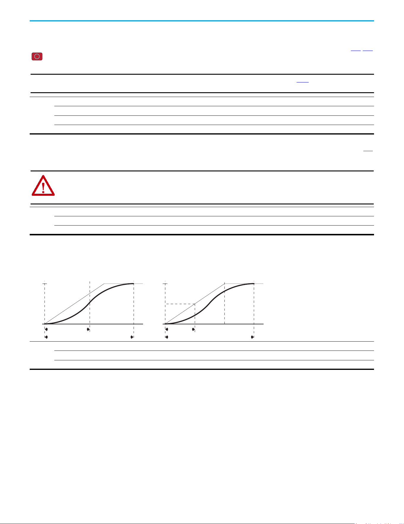
Rockwell Automation Publication 520-UM001N-EN-E - July 2024 119
Chapter 3 Programming and Parameters
Advanced Program Group (continued)
A437 [DB Resistor Sel] Related Parameters: A438, A550
Stop drive before changing this parameter.
Enables/disables external dynamic braking and selects the level of resistor protection.
Options
0 “Disabled” (Default)
1“Norml RA Res” 5%
2 “NoProtection” 100%
3...99“3...99% DutyCycle”
IMPORTANT
When A437 [DB Resistor Sel] is set to a value greater than “0”, the value set in parameter A550 [Bus Reg Enable] does
not take effect.
A438 [DB Threshold] Related Parameters: A437
Sets the DC bus voltage threshold for Dynamic Brake operation. If DC bus voltage rises above this level, Dynamic Brake turns on. Lower values make the dynamic braking
function more responsive but may result in nuisance Dynamic Brake activation (IGBT can modulate continuously).
Values
Default: 100.0%
Min/Max: 10.0/110.0%
Display: 0.1%
ATTENTION: Equipment damage may result if this parameter is set to a value that causes the dynamic braking resistor to
dissipate excessive power. Parameter settings less than 100% should be carefully evaluated to ensure that the Dynamic
Brake resistor's wattage rating is not exceeded. In general, values less than 90% are not needed. This parameter's setting
is especially important if parameter A437 [DB Resistor Sel] is set to 2 “NoProtection”.
A439 [S Curve %]
Enables a fixed shape S-curve that is applied to the acceleration and deceleration ramps (including jog).
S-Curve Time = (Accel or Decel Time) x (S-Curve Setting in percentage)
Values
Default: 0%
Min/Max: 0/100%
Display: 1%
S-Curve Time
Total Time to Accelerate = Accel Time + S-Curve Time
50% S-Curve
Target
vel
Target
vel/2
S-Curve Time = Accel Time
Total Time to Accelerate = Accel Time + S-Curve Time
100% S-Curve
Target
vel
Example:
Accel Time = 10 s
S-Curve Setting = 30%
S-Curve Time = 10 x 0.3 = 3 s
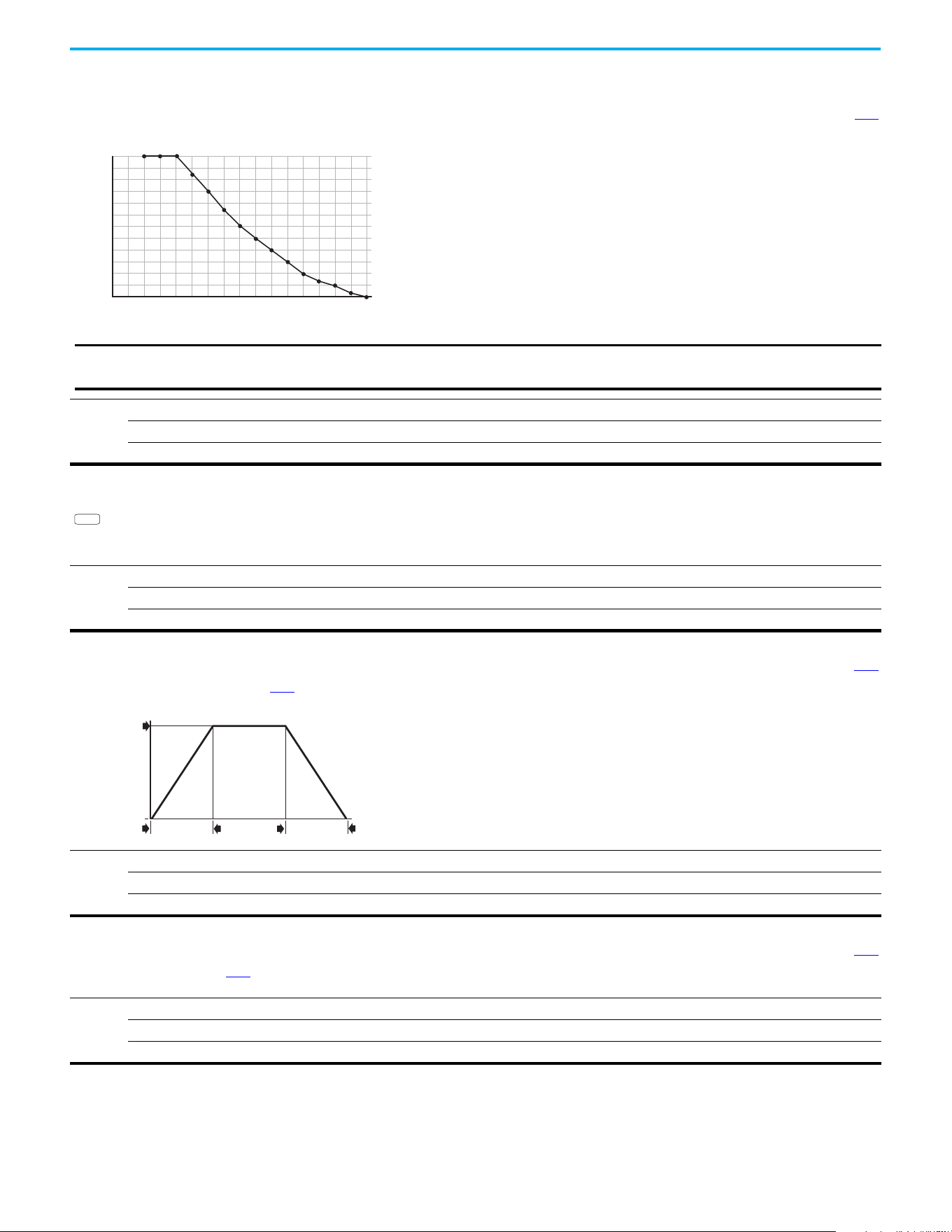
120 Rockwell Automation Publication 520-UM001N-EN-E - July 2024
Chapter 3 Programming and Parameters
Advanced Program Group (continued)
A440 [PWM Frequency] Related Parameters: A540
Sets the carrier frequency for the PWM output waveform. The chart below provides derating guidelines based on the PWM frequency setting.
Values
Default: 4.0 kHz
Min/Max: 2.0/16.0 kHz
Display: 0.1 kHz
% Output Curent (A)
60
80
85
75
70
95
100
90
65
55
50
45
40
Carrier Frequency (kHz)
8
7
6
54321
15
14
1613
1211109
0
IMPORTANT
Ignoring derating guidelines can cause reduced drive performance. The drive may automatically reduce the PWM
carrier frequency at low output speeds, unless prevented from doing so by A540 [Var PWM Disable].
If Vector mode (open loop) is selected and 16 kHz is selected, the
drive forcibly reduces the carrier frequency to 8 kHz.
A441 [Droop Hertz@ FLA]
PowerFlex 525 only
Reduces the frequency based on current. This frequency is subtracted from the commanded output frequency. Generally Slip and Droop would not both be used, but if both
are enabled they simply subtract from each other. Typically used in load sharing schemes.
Values
Default: 0.0 Hz
Min/Max: 0.0/10.0 Hz
Display: 0.1 Hz
PF 525
A442 [Accel Time 2] Related Parameters: P044
Time for the drive to ramp from 0.0 Hz to P044 [Maximum Freq] if Accel Time 2 is selected.
Accel Rate = [Maximum Freq] / [Accel Time]
Values
Default: 10.00 s
Min/Max: 0.00/600.00 s
Display: 0.01 s
Speed
0
Time
[Maximum Freq]
[Accel Time x]
[Decel Time x]
0
Acceleration
Deceleration
A443 [Decel Time 2] Related Parameters: P044
Time for the drive to ramp from P044 [Maximum Freq] to 0.0 Hz if Decel Time 2 is selected.
Decel Rate = [Maximum Freq] / [Decel Time]
Values
Default: 10.00 s
Min/Max: 0.00/600.00 s
Display: 0.01 s
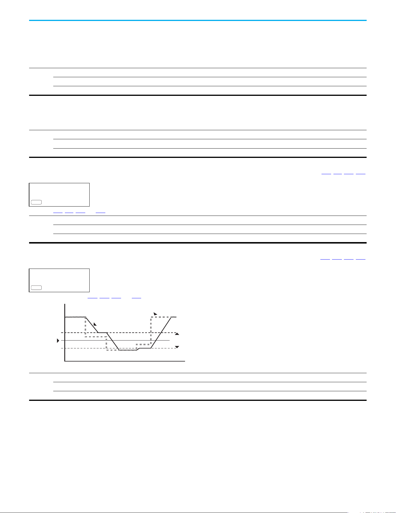
Rockwell Automation Publication 520-UM001N-EN-E - July 2024 121
Chapter 3 Programming and Parameters
Advanced Program Group (continued)
A444 [Accel Time 3]
A446 [Accel Time 4]
Sets the rate of acceleration for all speed increases when selected by digital inputs.
Values
Default: 10.00 s
Min/Max: 0.00/600.00 s
Display: 0.01 s
A445 [Decel Time 3]
A447 [Decel Time 4]
Sets the rate of deceleration for all speed decreases when selected by digital inputs.
Values
Default: 10.00 s
Min/Max: 0.00/600.00 s
Display: 0.01 s
A448 [Skip Frequency 1] Related Parameters: A449, A451, A453, A455
A450 [Skip Frequency 2]
A452 [Skip Frequency 3]
A454 [Skip Frequency 4]
PowerFlex 525 only
Works with A449, A451, A453, and A455 [Skip Freq Band x] creating a range of frequencies at which the drive does not operate continuously.
Values
Default: 0.0 Hz (Disabled)
Min/Max: 0.0/500.0 Hz
Display: 0.1 Hz
PF 525
A449 [Skip Freq Band 1] Related Parameters: A448, A450, A452, A454
A451 [Skip Freq Band 2]
A453 [Skip Freq Band 3]
A455 [Skip Freq Band 4]
PowerFlex 525 only
Determines the band around A448, A450, A452, and A454 [Skip Frequency x].
Values
Default: 0.0 Hz
Min/Max: 0.0/30.0 Hz
Display: 0.1 Hz
PF 525
Frequency
Time
Skip Frequency
Command
Frequency
Drive Output
Frequency
2x Skip
Frequency Band
122 Rockwell Automation Publication 520-UM001N-EN-E - July 2024
Chapter 3 Programming and Parameters
Advanced Program Group (continued)
A456 [PID 1 Trim Hi]
A468 [PID 2 Trim Hi]
PowerFlex 525 only
Scales the upper value of the trim frequency when trim is active.
Values
Default: 60.0 Hz
Min/Max: 0.0/500.0 Hz
Display: 0.1 Hz
PF 525
A457 [PID 1 Trim Lo]
A469 [PID 2 Trim Lo]
PowerFlex 525 only
Scales the lower value of the trim frequency when trim is active.
Values
Default: 0.0 Hz
Min/Max: 0.0/500.0 Hz
Display: 0.1 Hz
PF 525
A458 [PID 1 Trim Sel]
A470 [PID 2 Trim Sel]
PowerFlex 525 only
Stop drive before changing this parameter.
Sets the PID output as trim to the source reference.
Options
0 “Disabled” (Default) PID Trim is disabled.
1 “TrimOn Pot”
2 “TrimOn Keypd”
3 “TrimOn DSI”
4 “TrimOn NetOp”
5 “TrimOn 0-10V”
6 “TrimOn 4-20”
7 “TrimOn Prset”
8 “TrimOn AnMlt”
(1)
9 “TrimOn MOP”
10 “TrimOn Pulse”
11 “TrimOn Slgic”
(1)
12 “TrimOn Encdr”
(1)
13 “TrimOn ENet”
(1)
(1) Setting is specific to PowerFlex 525 drives only.
PF 525
Rockwell Automation Publication 520-UM001N-EN-E - July 2024 123
Chapter 3 Programming and Parameters
Advanced Program Group (continued)
A459 [PID 1 Ref Sel]
A471 [PID 2 Ref Sel]
PowerFlex 525 only
Stop drive before changing this parameter.
Selects the source of the PID reference.
Options
0 “PID Setpoint” (Default)
1 “Drive Pot”
2“Keypad Freq”
3 “Serial/DSI”
4 “Network Opt”
5“0-10V Input”
6 “4-20mA Input”
7 “Preset Freq”
8 “AnlgIn Multi”
(1)
9“MOP Freq”
10 “Pulse Input”
11 “Step Logic”
(1)
12 “Encoder”
(1)
13 “EtherNet/IP”
(1)
(1) Setting is specific to PowerFlex 525 drives only.
PF 525
A460 [PID 1 Fdback Sel]
A472 [PID 2 Fdback Sel]
PowerFlex 525 only
Selects the source of the PID feedback.
Options
0 “0-10V Input” (Default) Note: PID does not function with bipolar input. Negative voltages are ignored and treated as zero.
1 “4-20mA Input”
2 “Serial/DSI”
3 “Network Opt”
4 “Pulse Input”
5“Encoder”
(1)
6“EtherNet/IP”
(1)
(1) Setting is specific to PowerFlex 525 drives only.
PF 525
A461 [PID 1 Prop Gain] Related Parameters: A459, A471
A473 [PID 2 Prop Gain]
PowerFlex 525 only
Sets the value for the PID proportional component when the PID mode is enabled.
Values
Default: 0.01
Min/Max: 0.00/99.99
Display: 0.01
PF 525
124 Rockwell Automation Publication 520-UM001N-EN-E - July 2024
Chapter 3 Programming and Parameters
Advanced Program Group (continued)
A462 [PID 1 Integ Time] Related Parameters: A459, A471
A474 [PID 2 Integ Time]
PowerFlex 525 only
Sets the value for the PID integral component when PID mode is enabled.
Values
Default: 2.0 s
Min/Max: 0.0/999.9 s
Display: 0.1 s
PF 525
A463 [PID 1 Diff Rate] Related Parameters: A459, A471
A475 [PID 2 Diff Rate]
PowerFlex 525 only
Sets the value (in 1/second) for the PID differential component when PID mode is enabled.
Values
Default: 0.00
Min/Max: 0.00/99.99
Display: 0.01
PF 525
A464 [PID 1 Setpoint] Related Parameters: A459, A471
A476 [PID 2 Setpoint]
PowerFlex 525 only
Provides an internal fixed value for the process setpoint when PID mode is enabled.
Values
Default: 0.0%
Min/Max: 0.0/100.0%
Display: 0.1%
PF 525
A465 [PID 1 Deadband]
A477 [PID 2 Deadband]
PowerFlex 525 only
Sets a range, in percent above and below the PID Reference, that the PID output ignores.
Values
Default: 0.0%
Min/Max: 0.0/10.0%
Display: 0.1%
PF 525
A466 [PID 1 Preload]
A478 [PID 2 Preload]
PowerFlex 525 only
Sets the value that is used to preload the integral component on start or enable.
Values
Default: 0.0 Hz
Min/Max: 0.0/500.0 Hz
Display: 0.1 Hz
PF 525
A467 [PID 1 Invert Err]
A479 [PID 2 Invert Err]
PowerFlex 525 only
Changes the sign of the PID error.
Options
0 “Normal” (Default)
1 “Inverted”
PF 525
Rockwell Automation Publication 520-UM001N-EN-E - July 2024 125
Chapter 3 Programming and Parameters
Advanced Program Group (continued)
A481 [Process Disp Lo] Related Parameters: b010, P043
Sets the value that is displayed in b010 [Process Display] when the drive is running at P043 [Minimum Freq].
Values
Default: 0.00
Min/Max: 0.00/99.99
Display: 0.01
A482 [Process Disp Hi] Related Parameters: b010, P044
Sets the value that is displayed in b010 [Process Display] when the drive is running at P044 [Maximum Freq].
Values
Default: 0.00
Min/Max: 0.00/99.99
Display: 0.01
A483 [Testpoint Sel]
Used by Rockwell Automation field service personnel.
Values
Default: 400
Min/Max: 0/FFFF
Display: 1
A484 [Current Limit 1] Related Parameters: P033
Maximum output current allowed before current limiting occurs.
Values
Default: Drive Rated Amps x 1.1 (Normal Duty); Drive Rated Amps x 1.5 (Heavy Duty)
Min/Max: 0.0/Drive Rated Amps x 1.5 (Normal Duty); Drive Rated Amps x 1.8 (Heavy Duty)
Display: 0.1 A
A485 [Current Limit 2] Related Parameters: P033
PowerFlex 525 only
Maximum output current allowed before current limiting occurs.
Values
Default: Drive Rated Amps x 1.1
Min/Max: 0.0/Drive Rated Amps x 1.5 (Normal Duty); Drive Rated Amps x 1.8 (Heavy Duty)
Display: 0.1 A
PF 525
A486 [Shear Pin1 Level] Related Parameters: A487, A489
A488 [Shear Pin2 Level]
PowerFlex 525 only
Sets the value of current at which the shear pin fault occurs after the time set in A487, A489 [Shear Pin x Time]. Setting the value at 0.0 A disables this function.
Values
Default: 0.0 A (Disabled)
Min/Max: 0.0/(Drive Rated Amps x 2)
Display: 0.1 A
PF 525
A487 [Shear Pin 1 Time] Related Parameters: A486, A488
A489 [Shear Pin 2 Time]
PowerFlex 525 only
Sets the continuous time that the drive must be at or above the value set in A486, A488 [Shear Pinx Level] before a shear pin fault occurs.
Values
Default: 0.00 s
Min/Max: 0.00/30.00 s
Display: 0.01 s
PF 525
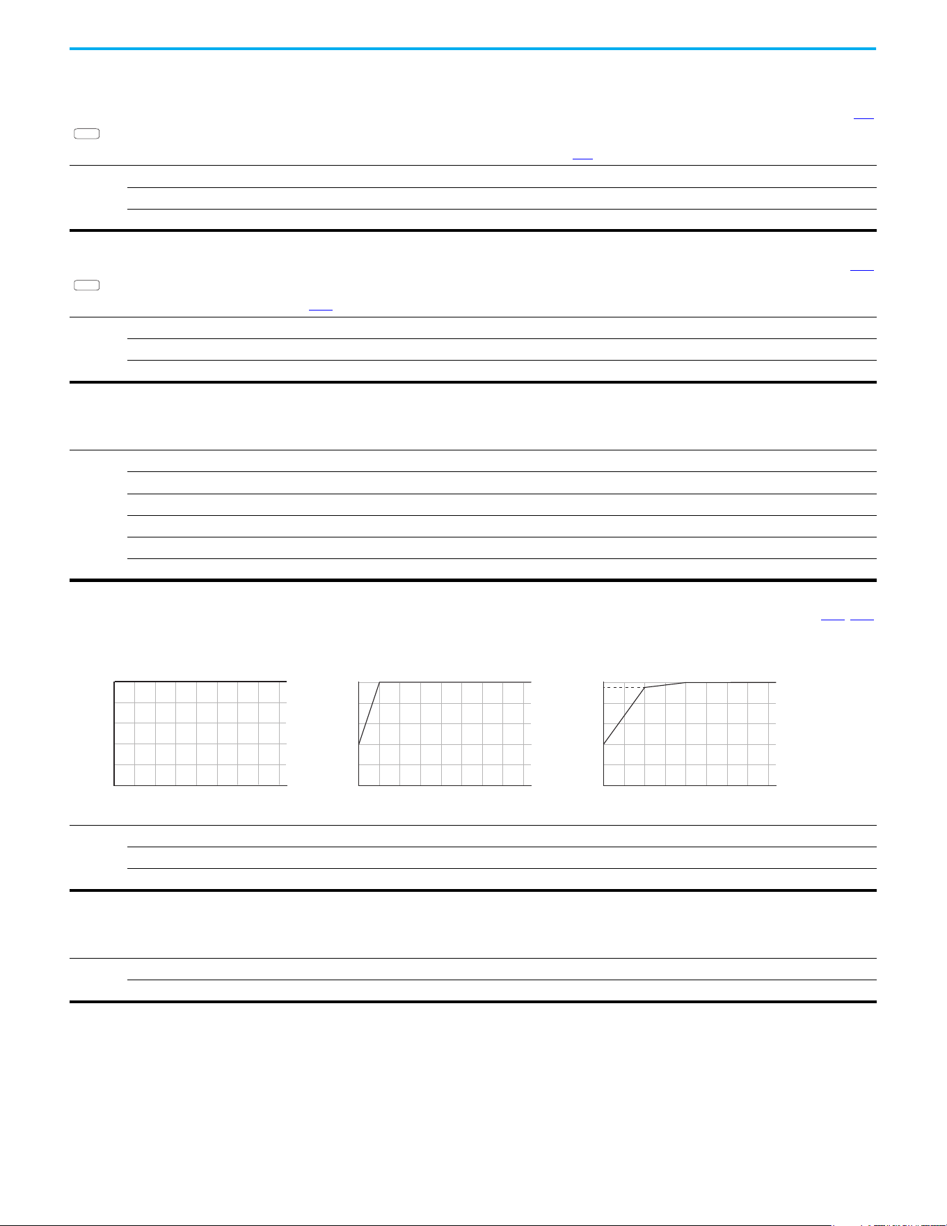
126 Rockwell Automation Publication 520-UM001N-EN-E - July 2024
Chapter 3 Programming and Parameters
Advanced Program Group (continued)
A490 [Load Loss Level] Related Parameters: A491
PowerFlex 525 only
Provides a software trip (Load Loss fault) when the current drops below this level for the time specified in A491 [Load Loss Time].
Values
Default: 0.0 A
Min/Max: 0.0/Drive Rated Amps
Display: 0.1 A
PF 525
A491 [Load Loss Time] Related Parameters: A490
PowerFlex 525 only
Sets the required time for the current to be below A490 [Load Loss Level] before a Load Loss fault occurs.
Values
Default: 0 s
Min/Max: 0/9999 s
Display: 1 s
PF 525
A492 [Stall Fault Time]
Sets the time that the drive remains in stall mode before a fault is issued.
Options
0“60 Seconds” (Default)
1 “120 Seconds”
2 “240 Seconds”
3 “360 Seconds”
4“480 Seconds”
5 “Flt Disabled”
A493 [Motor OL Select] Related Parameters: P032, P033
Drive provides Class 10 overload protection. Settings 0…2 select the derating factor for the I
2
t overload function.
Options
0“No Derate” (Default)
1 “Min Derate”
2 “Max Derate”
Min Derate
0
80
100
60
40
20
% of [Motor OL Curent]
No Derate
0
80
100
60
40
20
% of [Motor NP Hertz]
% of [Motor OL Curent]
% of [Motor NP Hertz]
% of [Motor OL Curent]
% of [Motor NP Hertz]
Max Derate
0
80
100
95
60
40
20
0
200
175
150
125100755025
0
200
175
150
125100755025
0
200
175
150
125100755025
A494 [Motor OL Ret]
Selects whether the motor overload counter is saved on power-down or reset on power-up.
Options
0 “Reset” (Default)
1“Save”

Rockwell Automation Publication 520-UM001N-EN-E - July 2024 127
Chapter 3 Programming and Parameters
Advanced Program Group (continued)
A495 [Drive OL Mode]
Determines how the drive handles overload conditions that would otherwise cause the drive to fault.
Options
0“Disabled”
1 “Reduce CLim”
2 “Reduce PWM”
3 “Both-PWM 1st” (Default)
A496 [IR Voltage Drop] Related Parameters: P040
Value of volts dropped across the resistance of the motor stator (autotune) for induction motor.
Values
Default: Based on Drive Rating
Min/Max: 0.0/600.0VAC
Display: 0.1VAC
A497 [Flux Current Ref] Related Parameters: P040
This is the current necessary for full motor flux. The value should be set to the full speed no-load current of the motor.
Values
Default: Based on Drive Rating
Min/Max: 0.00/(Drive Rated Amps x 1.4)
Display: 0.01 A
A498 [Motor Rr]
PowerFlex 525 only
Rotor resistance of induction motor. The value of this parameter populates when a full rotate tune is performed.
Values
Default: Based on Drive Rating
Min/Max: 0.00/655.35 ohm
Display: 0.01 ohm
PF 525
A499 [Motor Lm]
PowerFlex 525 only
Mutual Inductance of induction motor. The value of this parameter populates when a full rotate tune is performed.
Values
Default: Based on Drive Rating
Min/Max: 0.0/6553.5 mH
Display: 0.1 mH
PF 525
A500 [Motor Lx]
PowerFlex 525 only
Leakage Inductance of induction motor. The value of this parameter populates when a full rotate tune is performed.
Values
Default: Based on Drive Rating
Min/Max: 0.0/6553.5 mH
Display: 0.1 mH
PF 525
A501 [PM IR Voltage]
PowerFlex 525 only
(With FRN 5.xxx and later.)
Voltage across the stator resistance of the PM or SynRM motor at the rated motor current that is displayed in line-to-line rms value.
Values
Default: 11.50V
Min/Max: 0.00/655.35V
Display: 0.01V
PF 525

128 Rockwell Automation Publication 520-UM001N-EN-E - July 2024
Chapter 3 Programming and Parameters
Advanced Program Group (continued)
A502 [PM IXd Voltage]
PowerFlex 525 only
(With FRN 5.xxx and later.)
Voltage across the d-axis stator inductance of the PM or SynRM motor at the rated motor current and the rated motor frequency that is displayed in line-to-line rms value.
Values
Default: 17.91V
Min/Max: 0.00/655.35V
Display: 0.01V
PF 525
A503 [PM IXq Voltage]
PowerFlex 525 only
(With FRN 5.xxx and later.)
Voltage across the q-axis stator inductance of the PM or SynRM motor at the rated motor current and the rated motor frequency that is displayed in line-to-line rms value.
Values
Default: 53.21V
Min/Max: 0.00/655.35V
Display: 0.01V
PF 525
A504 [PM BEMF Voltage]
PowerFlex 525 only
(With FRN 5.xxx and later.)
Back electromotive force (EMF) voltage of the PM or SynRM motor.
Values
Default: 328.0 V - PM, 164.0 V - SynRM
Min/Max: 0.0/1200.0 V
Display: 0.1V
PF 525
A509 [Speed Reg Sel] Related Parameters: A521, A522, A523, A524, A525, A526
PowerFlex 525 only
Determines if PI gain of the “Vector” control mode speed regulator is set automatically or manually. This parameter automatically sets parameters A521…A526.
Options
0 “Automatic” (Default)
1“Manual”
PF 525
A510 [Freq 1]
A512 [Freq 2]
A514 [Freq 3]
PowerFlex 525 only
Sets the “Vector” control mode frequency.
Values
Default:
Freq 1:
Freq 2:
Freq 3:
8.33%
15.00%
20.00%
Min/Max: 0.00/200.00%
Display: 0.01%
PF 525
A511 [Freq 1 BW]
A513 [Freq 2 BW]
A515 [Freq 3 BW]
PowerFlex 525 only
Speed control loop bandwidth for “Vector” control mode.
Values
Default: 10 Hz
Min/Max: 0/40 Hz
Display: 1 Hz
PF 525

Rockwell Automation Publication 520-UM001N-EN-E - July 2024 129
Chapter 3 Programming and Parameters
Advanced Program Group (continued)
A516 [PM Initial Sel]
PowerFlex 525 only
(With FRN 5.xxx and later.)
PM initial angle detect.
Options
0“Align” (Default)
1 “HFI” High Frequency Injection to detect initial angle.
2 “Six Pulse”
PF 525
A517 [PM DC Inject Cur]
PowerFlex 525 only
(With FRN 5.xxx and later.)
Maximum DC current in amps applied to the motor to reset the rotor position of a PM motor.
Values
Default: 30%
Min/Max: 0/300%
Display: 1%
PF 525
A518 [PM Align Time]
PowerFlex 525 only
(With FRN 5.xxx and later.)
Magnetic pole reorientation time.
Values
Default: 0.7 s
Min/Max: 0.0/60.0 s
Display: 0.1 s
PF 525
A519 [PM HFI NS Cur]
PowerFlex 525 only
(With FRN 5.xxx and later.)
High Frequency Injection (HFI) North South Current to detect N/S Magnet.
Values
Default: 100%
Min/Max: 0/300%
Display: 1%
PF 525
A520 [PM Bus Reg Kd]
PowerFlex 525 only
(With FRN 5.xxx and later.)
Derivative gain for bus regulator.
Values
Default: 2
Min/Max: 0/500
Display: 1
PF 525
A521 [Freq 1 Kp] Related Parameters: A509, A510
A523 [Freq 2 Kp]
A525 [Freq 3 Kp]
PowerFlex 525 only
Sets P-gain of “Vector” control mode when in frequency region 1, 2 or 3 for faster speed response during dynamic-state where motor is still accelerating. If A509 [Speed
Reg Sel] is set to 1 “Manual”, these parameters can be changed.
Values
Default: 100.0%
Min/Max: 0.0/500.0%
Display: 0.1%
PF 525
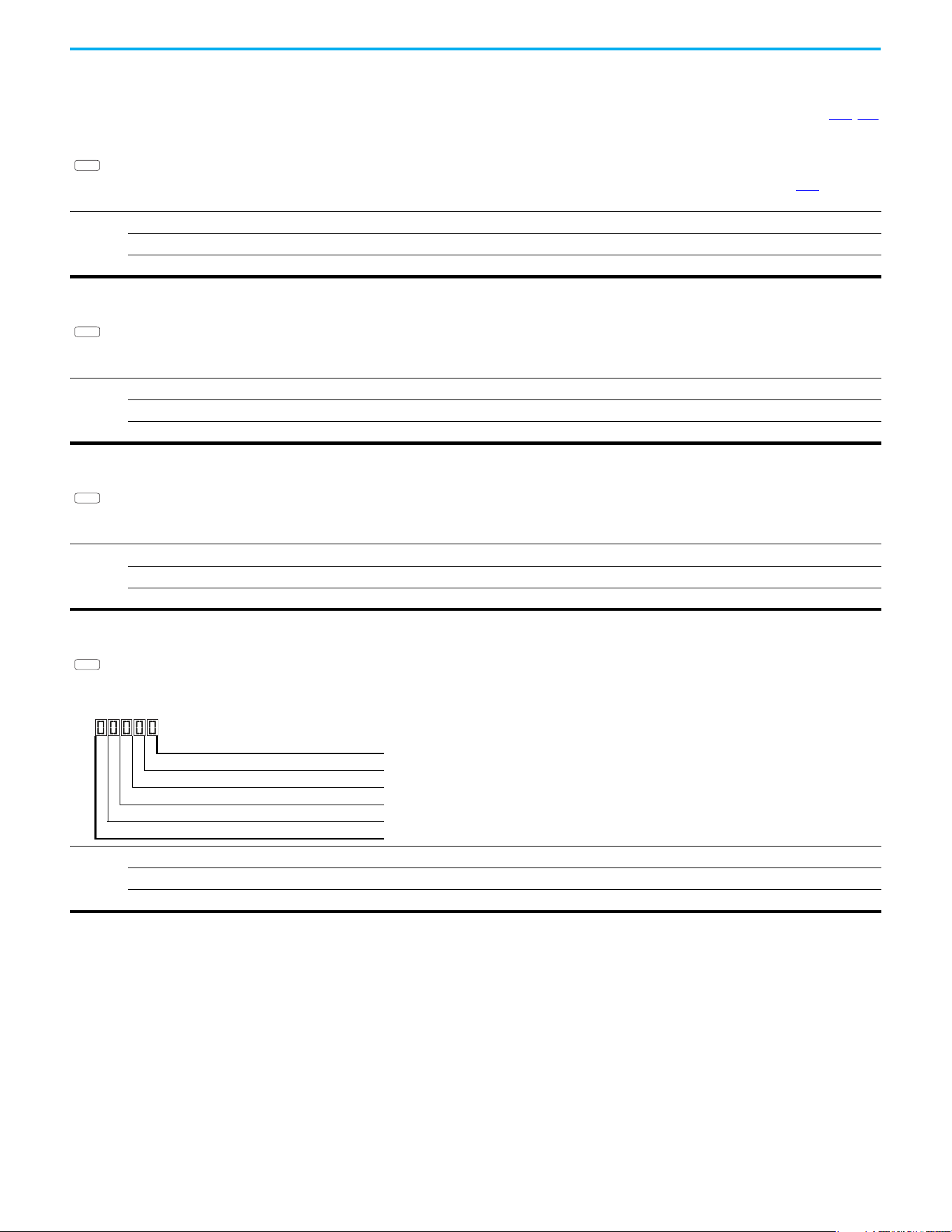
130 Rockwell Automation Publication 520-UM001N-EN-E - July 2024
Chapter 3 Programming and Parameters
Advanced Program Group (continued)
A522 [Freq 1 Ki] Related Parameters: A509, A510
A524 [Freq 2 Ki]
A526 [Freq 3 Ki]
PowerFlex 525 only
Sets I-gain of “Vector” control mode when in frequency region 1, 2 or 3 for faster speed response during steady-state where motor is at its rated speed. If A509 [Speed Reg
Sel] is set to 1 “Manual”, these parameters can be changed.
Values
Default: 0.100 s
Min/Max: 0.000/10.000 s
Display: 0.001 s
PF 525
A527 [PM FWKn 1 Kp]
PowerFlex 525 only
(With FRN 5.xxx and later.)
The gain to ensure good performance in field weakening region.
Values
Default: 350%
Min/Max: 0/2000%
Display: 1%
PF 525
A528 [PM FWKn 2 Kp]
PowerFlex 525 only
(With FRN 5.xxx and later.)
The gain to ensure robustness under step load in weakening region.
Values
Default: 300%
Min/Max: 100/8000%
Display: 1%
PF 525
A529 [PM Control Cfg]
PowerFlex 525 only
(With FRN 5.xxx and later.)
Control configuration for Feed Forward Decouple (FFD), Maximum Torque Per Amp (MTPA), and Load Disturbance Observer (LDOB).
Values
Default: 00111
Min/Max: 00000/00111
Display: 00000
PF 525
1 = Condition True, 0 = Condition False
FFD (Feed Forward Decouple) Digit 1
MTPA (Maximum Torque Per Amp) Digit 2
LDOB (Load Disturbance Observer) Digit 3
Not Used
Not Used
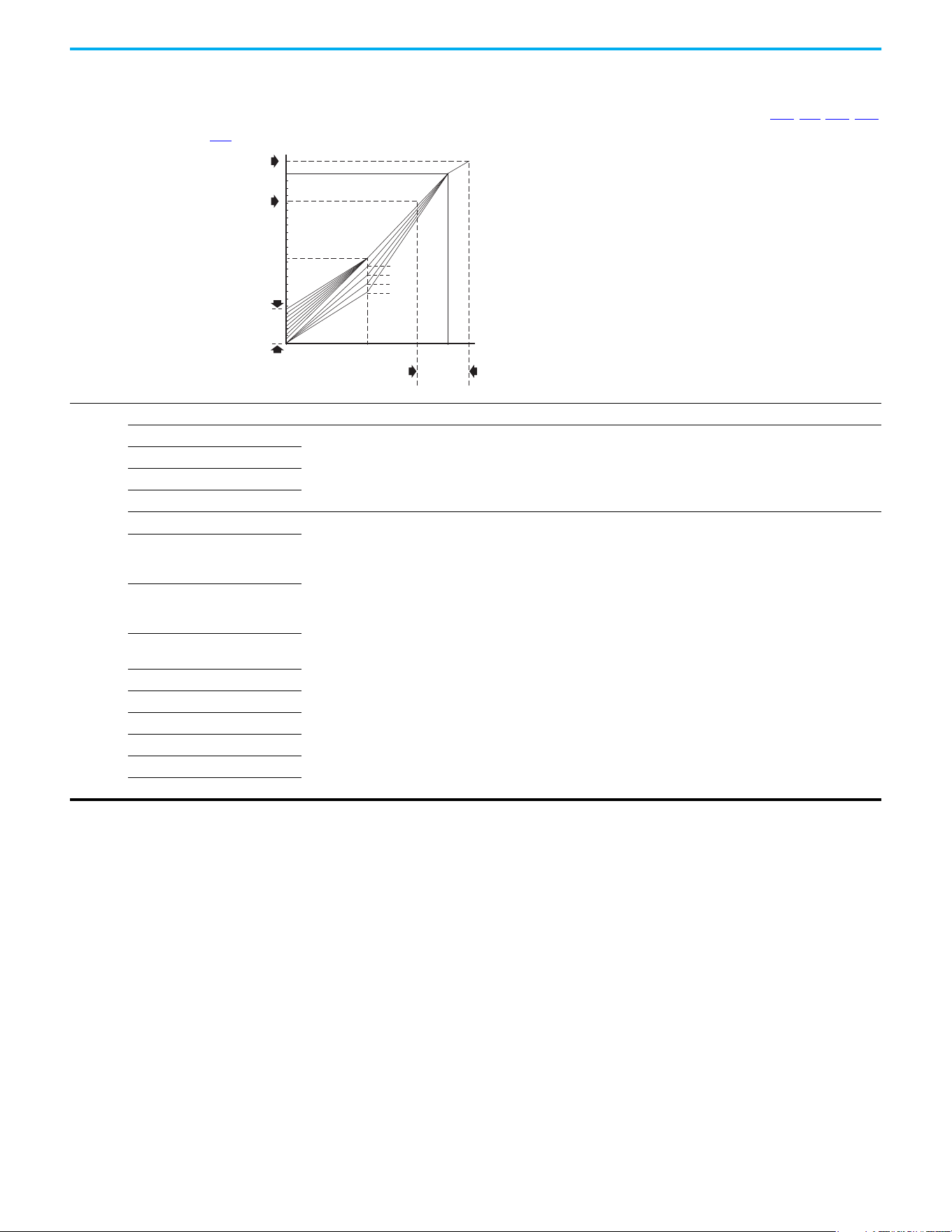
Rockwell Automation Publication 520-UM001N-EN-E - July 2024 131
Chapter 3 Programming and Parameters
Advanced Program Group (continued)
A530 [Boost Select] Related Parameters: b004, P031, P032, P039
Sets the boost voltage (% of P031 [Motor NP Volts]) and redefines the V/Hz curve. Only used for VHz control modes.
Options
0“Custom V/Hz”
1“30.0, VT”
Fan/Pump Curves (Variable Torque)
2“35.0, VT”
3“40.0, VT”
4“45.0, VT”
5 “0.0, no IR”
Boost Voltage (% of Base) (Constant Torque)
6“2.5, CT”
(Default for 400V and 600V
drives, 5 HP and above)
7“2.5, CT”
(Default for 200V drives, 5 HP
and above)
8“5.0, CT”
(Default for drives below 5 HP)
9“7.5, CT”
10 “10.0, CT”
11 “12.5, CT”
12 “15.0, CT”
13 “17.5, CT”
14 “20.0, CT”
% [Motor NP Hertz]
% [Motor NP Volts]
100
50
1/2 [Motor NP Volts]
[Maximum Voltage] can be set anywhere.
If it is > [Motor NP Volts] then it denes a point on the V/Hz curve
[Maximum Freq] can be set anywhere.
If it is > [Motor NP Hertz] then it denes a
point on the V/Hz curve
[Maximum Voltage] can be set anywhere.
If it is < [Motor NP Volts] then it functions as a limit only
(does not change the V/Hz curve)
[Maximum Freq] can be set anywhere.
If it is < [Motor NP Hertz] then it functions as a limit only
(does not change the V/Hz curve)
1/2
[Motor NP Hertz]
4
3
2
1
0 50 100
Settings
5...14
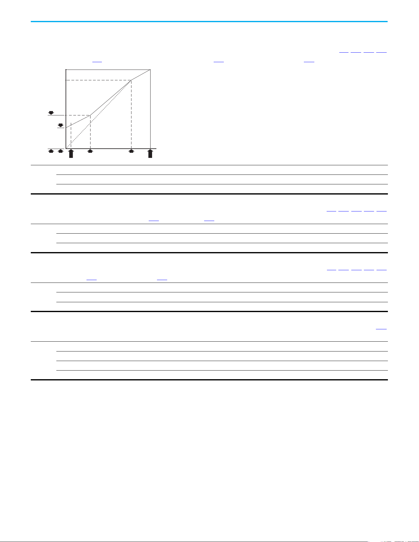
132 Rockwell Automation Publication 520-UM001N-EN-E - July 2024
Chapter 3 Programming and Parameters
Advanced Program Group (continued)
A531 [Start Boost] Related Parameters: P031, P032, P039, A530
Sets the boost voltage (% of P031 [Motor NP Volts]) and redefines the V/Hz curve when A530 [Boost Select] = 0 “Custom V/Hz” and P039 [Torque Perf Mode] = 0 “V/Hz”.
Values
Default: 2.5%
Min/Max: 0.0/25.0%
Display: 0.1%
Frequency
Voltage
[Break Frequency] [Motor NP Hertz]
[Maximum Freq]
[Start Boost]
[Motor NP Volts]
[Maximum Voltage]
[Break Voltage]
[Minimum Freq]
A532 [Break Voltage] Related Parameters: P031, P032, P039, A530, A533
Sets the voltage (in percent of [Base Frequency]) at the A533 [Break Frequency] if A530 [Boost Select] is set to 0 “Custom V/Hz”.
Values
Default: 25.0%
Min/Max: 0.0/100.0%
Display: 0.1%
A533 [Break Frequency] Related Parameters: P031, P032, P039, A530, A532
Sets the frequency where A532 [Break Voltage] is applied if A530 [Boost Select] is set to 0 “Custom V/Hz”.
Values
Default: 15.0 Hz
Min/Max: 0.0/500.0 Hz
Display: 0.1 Hz
A534 [Maximum Voltage] Related Parameters: b004
Sets the highest voltage that the drive outputs.
Values
Default: Drive Rated Volts
Min: 10V AC (on 230V AC Drives); 20V AC (on 460V AC Drives); 25V AC (on 600V AC Drives)
Max: 255V AC (on 230V AC Drives); 510V AC (on 460V AC Drives); 637.5V AC (on 600V AC Drives)
Display: 1V AC

Rockwell Automation Publication 520-UM001N-EN-E - July 2024 133
Chapter 3 Programming and Parameters
Advanced Program Group (continued)
A535 [Motor Fdbk Type] Related Parameters:P039, A537
Stop drive before changing this parameter.
Selects the encoder type.
(1)
Allowable Control Modes (See P039 [Torque Perf Mode]) Hardware Inputs
Options
0 “None” (Default) V/Hz, SVC, Economize, Vector, PM Control –
1“Pulse Train”
V/Hz, SVC, Economize, PM Control
[DigIn TermBlk 05] for PowerFlex 523
[DigIn TermBlk 07] for PowerFlex 525
2“Single Chan”
(2)
V/Hz, SVC, Economize, PM Control
Optional incremental encoder card (25-ENC-1)
3“Single Check”
(2)
V/Hz, SVC, Economize, PM Control
4“Quadrature”
(2)
V/Hz, SVC, Economize, Vector, PM Control
5“Quad Check”
(2)
V/Hz, SVC, Economize, Vector, PM Control
(1) Parameter is also available in PowerFlex 523 FRN 3.xxx and later.
(2) Setting is specific to PowerFlex 525 drives only.
ATTENTION: The loss of analog input, encoder, or other feedback may cause unintended speed or motion. Take
appropriate precautions to guard against possible unintended speed or motion.
A536 [Encoder PPR]
PowerFlex 525 only
Specifies the encoder Pulses Per Revolution (PPR) when an encoder is used.
To achieve speed range/accuracy for SVC and VVC closed loop control, a minimum of 1024 PPR encoder is recommended. The maximum encoder pulse is 250 kHz.
For more information, see Determine Encoder Pulse Per Revolution (PPR) Specification Based on Speed Resolution on page 221.
Values
Default: 1024 PPR
Min/Max: 1/20000 PPR
Display: 1 PPR
PF 525
A537 [Pulse In Scale] Related Parameters: t065, t067, A535
Sets the scale factor/gain for the Pulse Input when t065 [DigIn TermBlk 05] or t067 [DigIn TermBlk 07] is set to 52 “Pulse Train”, or A535 [Motor Fdbk Type] is set to 1 “Pulse
Train”.
Input frequency (Hz) / Pulse in Scale = Output frequency (Hz)
Values
Default: 64
Min/Max: 0/20000
Display: 1
A538 [Ki Speed Loop]
Sets the I-gain that is used in the PI calculation of the speed loop when feedback is used. Applicable to V/Hz and SVC modes in closed loop control only.
(1)
Values
Default: 2.0
Min/Max: 0.0/400.0
Display: 0.1
(1) Parameter is also available in PowerFlex 523 FRN 3.xxx and later.
A539 [Kp Speed Loop]
Sets the P-gain that is used in the PI calculation of the speed loop when feedback is used. Applicable to V/Hz and SVC modes in closed loop control only.
(1)
Values
Default: 0.5
Min/Max: 0.0/200.0
Display: 0.1
(1) Parameter is also available in PowerFlex 523 FRN 3.xxx and later.

134 Rockwell Automation Publication 520-UM001N-EN-E - July 2024
Chapter 3 Programming and Parameters
Advanced Program Group (continued)
A540 [Var PWM Disable] Related Parameters: A440
Stop drive before changing this parameter.
Enables/disables a feature that varies the carrier frequency for the PWM output waveform that is defined by A440 [PWM Frequency].
Options
0 “Enabled” (Default)
1“Disabled”
A541 [Auto Rstrt Tries] Related Parameters: A542
Sets the maximum number of times the drive attempts to reset a fault and restart. See Chapter 4 for more information on faults and fault codes.
Clear a Type 1 fault and restart the drive.
1. Set A541 [Auto Rstrt Tries] to a value other than “0”.
2. Set A542 [Auto Rstrt Delay] to a value other than “0”.
Clear an OverVoltage, UnderVoltage or Heatsink OvrTmp fault without restarting the drive.
1. Set A541 [Auto Rstrt Tries] to a value other than “0”.
2. Set A542
[Auto Rstrt Delay] to “0”.
Values
Default: 0
Min/Max: 0/9
Display: 1
ATTENTION: Equipment damage and/or personal injury may result if this parameter is used in an inappropriate
application. Do not use this function without considering applicable local, national, and international codes, standards,
regulations or industry guidelines.
A542 [Auto Rstrt Delay] Related Parameters: A541
Sets the time between restart attempts if A541 [Auto Rstrt Tries] is not zero.
Values
Default: 1.0 s
Min/Max: 0.0/120.0 s
Display: 0.1 s
A543 [Start At PowerUp]
Stop drive before changing this parameter.
Enables/disables drive start on power-up without a Run command being cycled. Requires a digital input that is configured for Run and a valid run signal.
Options
0 “Disabled” (Default)
1“Enabled”
ATTENTION: Equipment damage and/or personal injury may result if this parameter is used in an inappropriate
application. Do not use this function without considering applicable local, national, and international codes, standards,
regulations or industry guidelines.
A544 [Reverse Disable] Related Parameters: b006
Stop drive before changing this parameter.
Enables/disables the function that allows the direction of motor rotation to be changed.
Options
0 “Rev Enabled” (Default)
1“Rev Disabled”
A545 [Flying Start En]
Sets the condition that allows the drive to reconnect to a spinning motor at actual RPM.
Options
0 “Disabled” (Default)
1 “Enabled” Catch and ramp to commanded speed at every drive start.
Rockwell Automation Publication 520-UM001N-EN-E - July 2024 135
Chapter 3 Programming and Parameters
Advanced Program Group (continued)
A546 [FlyStrt CurLimit]
Used to determine when the drive has matched the motor frequency if Flying Start is enabled.
Values
Default: 65%
Min/Max: 30/200%
Display: 1%
A547 [Compensation]
Enables/disables correction options that may improve problems with motor instability.
Options
0 “Disabled” No compensation.
1 “Electrical” (Default) Some drive/motor combinations have inherent instabilities that are exhibited as non-sinusodial motor currents.
This setting attempts to correct this condition.
2 “Mechanical” Some motor/load combinations have mechanical resonances that can be excited by the drive current regulator.
This setting slows down the current regulator response and attempts to correct this condition.
3“Both”
A548 [Power Loss Mode]
Sets the reaction to a loss of input power.
Options
0 “Coast” (Default) Drive faults and motor coasts to a stop.
1 “Decel” Drive decelerates and attempts to keep the DC bus voltage above the undervoltage level.
A549 [Half Bus Enable]
Enables/disables the power ride-through function, which allows the drive to maintain power to the motor at 50% drive input voltage during short-term power sag
conditions.
Options
0 “Disabled” (Default)
1“Enabled”
ATTENTION: To guard against drive damage, a minimum line impedance must be provided to limit inrush current when
the power line recovers. The input impedance should be equal or greater than the equivalent of a 5% transformer with a
VA rating 6 times the drive's input VA rating if Half Bus is enabled.
A550 [Bus Reg Enable] Related Parameters: A437
Enables/disables the bus regulator.
Options
0“Disabled”
1 “Enabled” (Default)
A551 [Fault Clear]
Stop drive before changing this parameter.
Resets a fault and clears the fault queue.
Options
0 “Ready/Idle” (Default)
1 “Reset Fault” Resets the active fault but does not clear any fault buffer.
2 “Clear Buffer” Resets the active fault and clears all fault buffers to “0”.
A552 [Program Lock] Related Parameters: A553
Protects parameters against change by unauthorized personnel with a 4-digit access code.
Values
Default: 0000
Min/Max: 0000/9999
Display: 1111
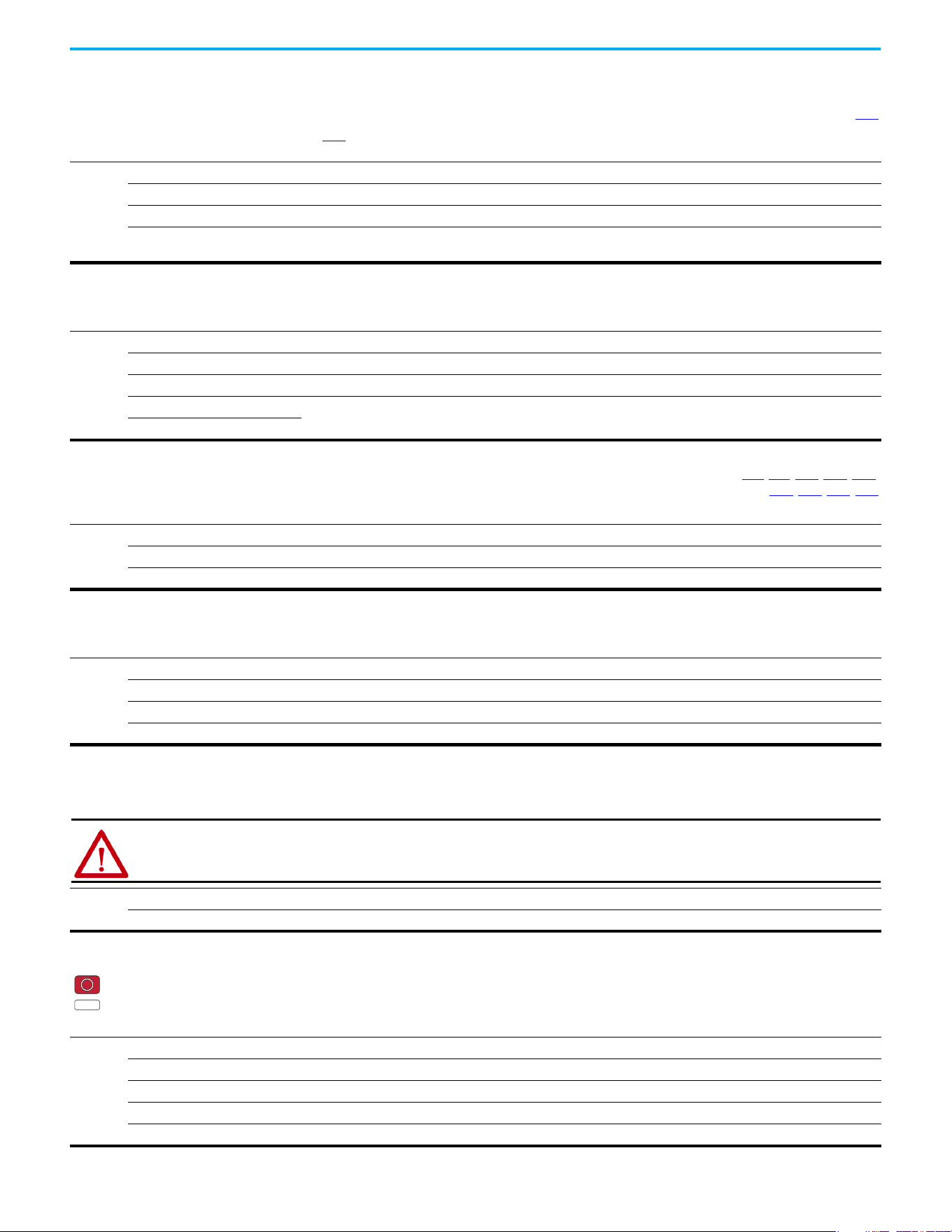
136 Rockwell Automation Publication 520-UM001N-EN-E - July 2024
Chapter 3 Programming and Parameters
Advanced Program Group (continued)
A553 [Program Lock Mod] Related Parameters: A552
Determines the lock mode that is used in parameter A552 [Program Lock]. When set to 2 or 3, A552 [Program Lock] is added to the custom group to allow unlocking of
parameters.
Options
0 “Full Lock” (Default) All parameters are locked except [Program Lock].
1 “Keypad Lock” All parameters are locked except [Program Lock] from keypad access but can still be accessed over communications.
2 “Custom Only” All parameters are locked and hidden except custom group and [Program Lock].
3 “KeyPd Custom” All parameters are locked and hidden except custom group and [Program Lock] from keypad access but can still be
accessed over communications.
A554 [Drv Ambient Sel]
Sets the maximum expected ambient of the drive when used above 50 °C. When ambient temperature is above 50 °C, the drive applies necessary current derating.
Options
0 “Normal” (Default)
1 “55C”
2“60C”
3“65C +Fan Kit”
Fan kit required.
4“70C +Fan Kit”
A555 [Reset Meters] Related Parameters: b019, b021, b022, b023, b024,
b025
, b026, d362, d363
Resets the values that are stored in the parameters that track fault times and energy usage.
Options
0 “Ready/Idle” (Default)
1 “Reset Meters” Resets kWh, MWh, Accum kWh, Cost, and CO2 Sav parameter values.
2 “Reset Time” Resets min, hr, and x10 hr.
A556 [Text Scroll]
Sets the scrolling speed of the text in the LCD display.
Options
0 “Off” No scroll.
1 “Low Speed”
2 “Mid Speed” (Default)
3 “High Speed”
A557 [Out Phas Loss En]
Enable/disable output phase loss detection.
Options
0“Disable” (Default)
1“Enable”
ATTENTION: Equipment damage and/or personal injury may result if this parameter is used in an inappropriate
application. Do not use this function without considering applicable local, national, and international codes, standards,
regulations or industry guidelines.
A558 [Positioning Mode]
Stop drive before changing this parameter.
PowerFlex 525 only
Defines the positioning transition mode that is used for the position steps.
Options
0 “Time Steps” (Default) Steps based on time.
1 “Preset Input” Preset inputs directly commands a given step.
2 “Step Logic” Use StepLogic Commands. Always start from Step 0.
3 “Preset StpL” Use Preset Inputs to determine starting step then StepLogic commands.
4 “StpLogic-Lst” Use StepLogic commands from last Step Logic step at last drive stop.
PF 525
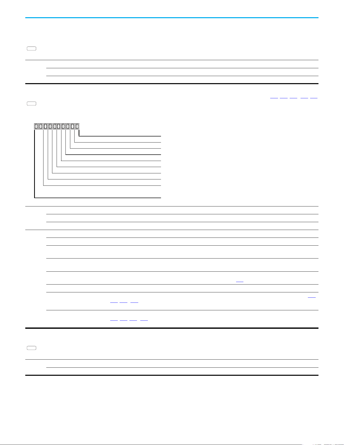
Rockwell Automation Publication 520-UM001N-EN-E - July 2024 137
Chapter 3 Programming and Parameters
Advanced Program Group (continued)
A559 [Counts Per Unit]
PowerFlex 525 only
Sets the number of encoder counts equal to one user-defined unit.
Values
Default: 4096
Min/Max: 1/32000
Display: 1
PF 525
A560 [Enh Control Word] Related Parameters: t062, t063, t065…t068, A571
PowerFlex 525 only
Allows control of positioning and other functions through parameter control for use over comms. The functions replicate the digital input options and function in the same
way.
Values
Default: 0000 0000
Min/Max: 0000 0000/1111 1111
Display: 0000 0000
Digits
0 “Home Limit” In Positioning mode, this indicates that the drive is at the home position.
1 “Find Home” When set, the next start command causes the drive to find home. Set this bit to 0 after completing the homing routine.
2 “Hold Step” In Positioning mode, this input overrides other inputs and causes the drive to remain at its current step (running at zero
speed once it reaches its position) until released.
3 “Pos Redefine” In Positioning mode, this input resets the home position to the current position of the machine. Set this bit to 0 after
completing the homing routine.
4 “Sync Enable” Must be used to hold the existing frequency when Sync Time is set to enable speed synchronization. When this bit is reset
to zero the drive accelerates to the new commanded frequency based on A571
[Sync Time] setting.
5 “Traverse Dis” When set the traverse function is disabled.
6 “Logic In 1” This provides an identical function as the “Logic In1” Digital Input option. This bit is logically ORed with a digital input t062
,
t063, t065…t068 [DigIn TermBlk xx] set to 24 “Logic In1”. It can be used to move through the StepLogic functions (speed or
position) using comms control without requiring actual digital input transitions.
7 “Logic In 2” This provides and identical function as the “Logic In2” Digital Input option. This bit is logically ORed with a digital input
t062
, t063, t065…t068 [DigIn TermBlk xx] set to 25 “Logic In2”. It can be used to move through the StepLogic functions
(speed or position) using comms control without requiring actual digital input transitions.
PF 525
1 = Input Present, 0 = Input Not Present
Home Limit Digit 1
Find Home Digit 2
Hold Step Digit 3
Pos Redefine Digit 4
Sync Enable Digit 5
Traverse Dis Digit 6
Logic In 1 Digit 7
Logic In 2 Digit 8
Not Used
A561 [Home Save]
PowerFlex 525 only
Determines whether the current position is saved on power down.
Options
0 “Home Reset” (Default) Position resets to zero on power-up.
1“Home Saved”
PF 525

138 Rockwell Automation Publication 520-UM001N-EN-E - July 2024
Chapter 3 Programming and Parameters
Advanced Program Group (continued)
A562 [Find Home Freq]
PowerFlex 525 only
Sets the maximum frequency that the drive uses when “Find Home” is issued.
Values
Default: 10.0 Hz
Min/Max: 0.1/500.0 Hz
Display: 0.1 Hz
PF 525
A563 [Find Home Dir]
Stop drive before changing this parameter.
PowerFlex 525 only
Sets the direction that the drive commands when “Find Home” is issued.
Options
0 “Forward” (Default)
1“Reverse”
PF 525
A564 [Encoder Pos Tol]
PowerFlex 525 only
Sets the “At Position” and the “At Home’ tolerance around the encoder count. The value is added to and subtracted from the target encoder unit value to create the
tolerance range.
Values
Default: 100
Min/Max: 1/50000
Display: 1
PF 525
A565 [Pos Reg Filter]
PowerFlex 525 only
Sets the error signal filter in the position regulator.
Values
Default: 8
Min/Max: 0/15
Display: 1
PF 525
A566 [Pos Reg Gain]
PowerFlex 525 only
Sets the gain adjustment for the position regulator.
Values
Default: 3.0
Min/Max: 0.0/200.0
Display: 0.1
PF 525
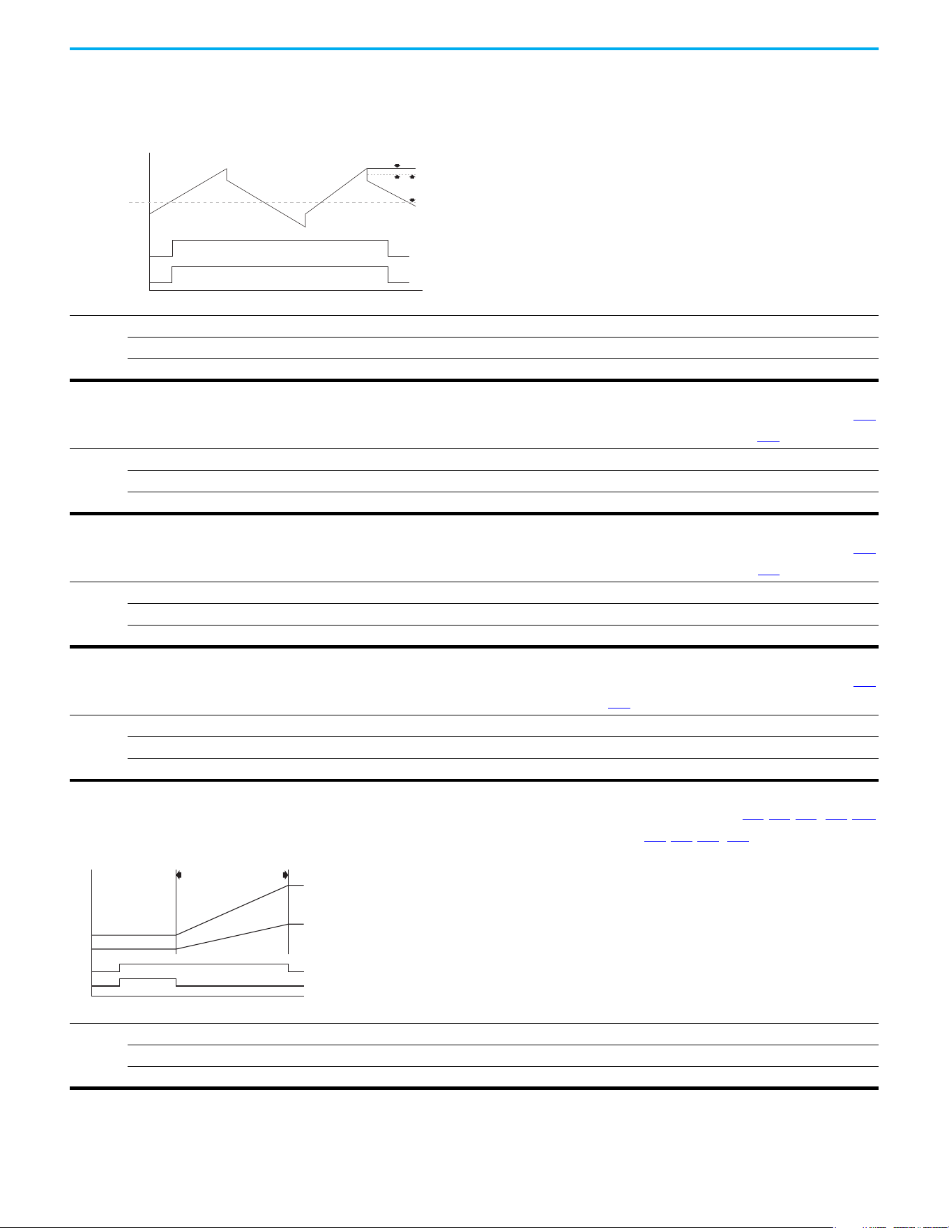
Rockwell Automation Publication 520-UM001N-EN-E - July 2024 139
Chapter 3 Programming and Parameters
Advanced Program Group (continued)
A567 [Max Traverse]
Sets the amplitude of triangle wave speed modulation.
Values
Default: 0.00 Hz
Min/Max: 0.00/300.00 Hz
Display: 0.01 Hz
Hertz
Seconds
[Max Traverse]
[P Jump]
[Output Freq]
[Fiber Status]
Traverse Enable Bit
Traverse Bit
A568 [Traverse Inc] Related Parameters: A567
Sets the time that is required for the Traverse function to accelerate from the minimum to the maximum traverse frequency. See the diagram at A567 [Max Traverse].
Values
Default: 0.00 s
Min/Max: 0.00/300.00 s
Display: 0.01 s
A569 [Traverse Dec] Related Parameters: A567
Sets the time that is required for the Traverse function to decelerate from the maximum to the minimum traverse frequency. See the diagram at A567 [Max Traverse].
Values
Default: 0.00 s
Min/Max: 0.00/300.00 s
Display: 0.01 s
A570 [P Jump] Related Parameters: A567
Sets the frequency amplitude that is added to or subtracted from the commanded frequency. See the diagram at A567 [Max Traverse].
Values
Default: 0.00 Hz
Min/Max: 0.00/300.00 Hz
Display: 0.01 Hz
A571 [Sync Time] Related Parameters: t062, t063, t065…t068, A560
Enables the function that holds the drive at the current frequency even if the commanded frequency changes. Used with t062, t063, t065…t068 [DigIn TermBlk xx] 32
“Sync Enable”.
Values
Default: 0.0 s
Min/Max: 0.0/3200.0 s
Display: 0.1 s
Hertz
Time
Speed Sync Bit
Change Ref's
[Sync Time]
Drive #1 and #2 Sync Enable Input
[Fiber Status]
New Drive #1 Reference
New Drive #2 Reference
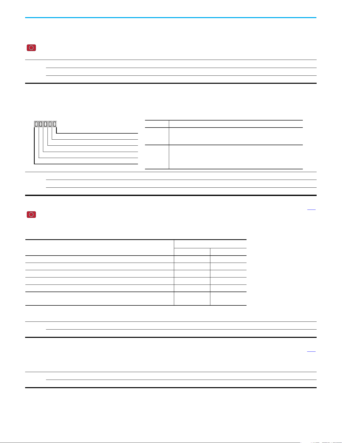
140 Rockwell Automation Publication 520-UM001N-EN-E - July 2024
Chapter 3 Programming and Parameters
Advanced Program Group (continued)
A572 [Speed Ratio]
Stop drive before changing this parameter.
Scales the drive speed command.
Values
Default: 1.00
Min/Max: 0.01/99.99
Display: 0.01
A573 [Mtr Options Cfg]
(With PowerFlex 525 FRN 2.xxx and later.)
(With PowerFlex 523 FRN 3.xxx and later.)
Sets the configuration of the motor option.
Values
Default: 11
Min/Max: 00/11
Display: 00
1 = Enabled, 0 = Disabled
Jerk Select Digit 1
ZeroSpd Slip Digit 2
Not Used
Not Used
Not Used
Options Description
Jerk Select
Limits the rate of change to the velocity reference for improved current
limiting. Set to 0 “Disabled” for positioning type applications with fast Accel
or Decel times.
ZeroSpd Slip
Sets slip compensation to 0.0 Hz when the following conditions are met:
• Commanded speed = 0.00 Hz
• Status of drive = “At speed”
• ZeroSpd Slip = 1 “Enabled”
A574 [RdyBit Mode Cfg] Related Parameters: d392
Stop drive before changing this parameter.
(With PowerFlex 525 FRN 3.xxx and later.)
(With PowerFlex 523 FRN 3.xxx and later.)
Determines which Stop conditions cause the drive’s Ready bit (Network Logic Status bit 1) to go low (0). A reset or power cycle is required after selection is made.
Options
0 “Standard” (Default)
1“Enhanced”
Ready Bit Status
(1)
(1) 1 = Active, 0 = Inactive
Stop Conditions Standard Enhanced
Drive fault 0 0
Stop digital input terminal 01/11 open 1 0
Holding down the drive’s keypad or the Remote DSI HIM Stop button 1 0
Stop commanded through Comms (Stop bit = 1) 1 0
Software (SW) Enable digital input terminal open 1 0
Safe Torque Off (STO) condition with value of t105 [Safety Open En] set to 1
“FaultDisabled”
(2)
(2) Condition is specific to PowerFlex 525 drives only.
00
A575 [Flux Braking En] Related Parameters: A550
(With PowerFlex 525 FRN 5.xxx and later.)
(With PowerFlex 523 FRN 3.xxx and later.)
Enables/disables flux braking.
Options
0“Disable” (Default)
1“Enable”

Rockwell Automation Publication 520-UM001N-EN-E - July 2024 141
Chapter 3 Programming and Parameters
Advanced Program Group (continued)
A576 [Phase Loss Level]
(With PowerFlex 525 FRN 5.xxx and later.)
(With PowerFlex 523 FRN 3.xxx and later.)
Output Phase Loss Level. Sets the threshold level that is used to determine an output phase loss condition.
Each motor phase must exceed this value. Decreasing this parameter's value lowers sensitivity.
Values
Default: 25.0% for Induction motor; 4.0% for PM motor
Min/Max: 0.0/100.0%
Display: 0.1%
A580 [Current Loop BW]
PowerFlex 525 only
(With FRN 5.xxx and later.)
Current loop bandwidth (0 = Automatically calculate the control gain of current loop).
Values
Default: 0 Hz
Min/Max: 0/65535 Hz
Display: 1 Hz
PF 525
A581 [PM Stable 1 Freq]
PowerFlex 525 only
(With FRN 5.xxx and later.)
The start frequency for stabilization loop (P032 [Motor NP Hertz] x A581 [PM Stable 1 Freq]).
Values
Default: 0%
Min/Max: 0/100%
Display: 1%
PF 525
A582 [PM Stable 2 Freq]
PowerFlex 525 only
(With FRN 5.xxx and later.)
Stabilization function will return to normal output after this frequency (P032 [Motor NP Hertz] x A582 [PM Stable 2 Freq]).
Values
Default: 45%
Min/Max: 0/100%
Display: 1%
PF 525
A583 [PM Stable 1 Kp]
PowerFlex 525 only
(With FRN 5.xxx and later.)
Percentage of the gain for stabilization loop. The gain is set in A584 [PM Stable 2 Kp].
Values
Default: 40%
Min/Max: 0/100%
Display: 1%
PF 525
A584 [PM Stable 2 Kp]
PowerFlex 525 only
(With FRN 5.xxx and later.)
The gain for stabilization loop.
Values
Default: 250%
Min/Max: 0/2000%
Display: 1%
PF 525

142 Rockwell Automation Publication 520-UM001N-EN-E - July 2024
Chapter 3 Programming and Parameters
Advanced Program Group (continued)
A585 [PM Stable Brk Pt]
PowerFlex 525 only
(With FRN 5.xxx and later.)
Percentage of rated power P037 [Motor NP Power] for the gain of (A584 [PM Stable 2 Kp] x A583 [PM Stable 1 Kp]).
Values
Default: 40%
Min/Max: 0/100%
Display: 1%
PF 525
A586 [PM Stepload Kp]
PowerFlex 525 only
(With FRN 5.xxx and later.)
The gain to ensure robustness under step load in low speed region.
Values
Default: 0%
Min/Max: 0/1000%
Display: 1%
PF 525
A587 [PM 1 Efficiency]
PowerFlex 525 only
(With FRN 5.xxx and later.)
Reduce full-load current.
Values
Default: 120%
Min/Max: 0/2000%
Display: 1%
PF 525
A588 [PM 2 Efficiency]
PowerFlex 525 only
(With FRN 5.xxx and later.)
Reduce no load current.
Values
Default: 500%
Min/Max: 0/2000%
Display: 1%
PF 525
A589 [PM Algor Sel] Related Parameters: A550
Stop drive before changing this parameter.
PowerFlex 525 only
(With FRN 5.xxx and later.)
Selects the algorithm to use with your motor. Check with the manufacturer of your motor to determine whether it is an iPM or sPM motor.
Options
0 “Algorithm 1” (Default) Suggested for most motors.
1 “Algorithm 2” Enable an embedded algorithm to reduce oscillation in output waveform (use with sPM motor only, do not enable for iPM
motor).
PF 525
A590 [SYNRM SW Freq]
PowerFlex 525 only
(With FRN 7.xxx and later.)
Switching Frequency point from Low-Speed Observer (Freq1) to High-Speed Observer (Freq2).
Values
Default: 10 Hz
Min/Max: 0/600 Hz
PF 525

Rockwell Automation Publication 520-UM001N-EN-E - July 2024 143
Chapter 3 Programming and Parameters
Advanced Program Group (continued)
A591 [SYNRM Flux Cur]
PowerFlex 525 only
(With FRN 7.xxx and later.)
SynRM Field Excitation Current.
Increasing the setting enhances no loading performance but has poor efficiency.
Decreasing the setting reduces no loading performance but good efficiency.
Values
Default: 35%
Min/Max: 0/150%
PF 525
A592 [SYNRM Freq1 Volt]
PowerFlex 525 only
(With FRN 7.xxx and later.)
The Amplitude of Injected Signal of Low-Speed Observer (Freq1).
Increasing the setting enhances the loading performance during Freq1 operation.
Values
Default: 30%
Min/Max: 0/100%
PF 525
A593 [SYNRM Freq1 Kp]
PowerFlex 525 only
(With FRN 7.xxx and later.)
The Scaling of bandwidth At Low-Speed Observer (Freq1).
Increasing the setting enhances the loading performance during low-speed (Freq1) operation but too high causes motor vibration.
Decreasing the setting causes the motor to stall during startup and low-speed (Freq1) operation.
When the motor running speed is lower than the switching frequency A590 adjust the setting.
Values
Default: 1.00
Min/Max: 0.01/5.00
PF 525
A594 [SYNRM Freq1 Comp]
PowerFlex 525 only
(With FRN 7.xxx and later.)
The Scaling of Mutual Inductance Compensation At Low-Speed Observer (Freq1).
Increasing or decreasing the setting enhances the loading performance during Freq1 operation depending on the motor.
Values
Default: 1.00
Min/Max: 0/10.00
PF 525
A595 [SYNRM Freq2 BW]
PowerFlex 525 only
(With FRN 7.xxx and later.)
The bandwidth At High-Speed Observer (Freq2).
Increasing the setting enhances the loading performance during high-speed (Freq2) operation but too high causes vibration.
Decreasing the setting causes the motor to stall during startup and high-speed (Freq2) operations.
When the motor running speed is higher than the switching frequency A590, adjust the setting.
Values
Default: 10 Hz
Min/Max: 0/50 Hz
PF 525
A596 [SYNRM Freq2 Kp]
PowerFlex 525 only
(With FRN 7.xxx and later.)
The Scaling of Magnetic linkage estimator At High-Speed Observer (Freq2).
To fine-tune the setting when motor is still not stable after adjustment A595.
Increasing the motor setting enhances the loading performance during high-speed (Freq2) operation but too high causes vibration.
Decreasing the setting causes the motor to stall during startup and high-speed (Freq2) operations.
When the motor running speed is higher than the switching frequency A590, adjust the setting.
Values
Default: 1.00
Min/Max: 0.1/10.00
PF 525

144 Rockwell Automation Publication 520-UM001N-EN-E - July 2024
Chapter 3 Programming and Parameters
Network Parameter Group This group contains parameters for the network option card that is installed.
See the network option card’s user manual for more information on the
available parameters.
Modified Parameter Group This group contains parameters that have their values changed from the
factory default.
When a parameter has its default value changed, it is automatically added to
this group. When a parameter has its value changed back to the factory default,
it is automatically removed from this group.
Fault and Diagnostic Group
F604 [Fault 4 Code] Related Parameters: b007…b009
F605 [Fault 5 Code]
F606 [Fault 6 Code]
F607 [Fault 7 Code]
F608 [Fault 8 Code]
F609 [Fault 9 Code]
F610 [Fault10 Code]
A code that represents a drive fault. The codes appear in these parameters in the order that they occur (b007 [Fault 1 Code] = the most recent fault). Repetitive faults are
only recorded once.
Values
Default: Read Only
Min/Max: F0/F127
Display: F0
F611 [Fault 1 Time-hr]
F613 [Fault 3 Time-hr]
F615 [Fault 5 Time-hr]
F612 [Fault 2 Time-hr] Related Parameters: d362
F614 [Fault 4 Time-hr]
F616 [Fault 6 Time-hr]
F618 [Fault 8 Time-hr]
F620 [Fault10 Time-hr]
PowerFlex 525 only
F617 [Fault 7 Time-hr]
F619 [Fault 9 Time-hr]
Displays the value of d362
[Elapsed Time-hr] when the fault occurs.
Values
Default: Read Only
Min/Max: 0/32767 hr
Display: 1 hr
PF 525
F621 [Fault 1 Time-min]
F623 [Fault 3 Time-min]
F625 [Fault 5 Time-min]
F622 [Fault 2 Time-min] Related Parameters: d363
F624 [Fault 4 Time-min]
F626 [Fault 6 Time-min]
F628 [Fault 8 Time-min]
F630 [Fault10 Time-min]
PowerFlex 525 only
F627 [Fault 7 Time-min]
F629 [Fault 9 Time-min]
Displays the value of d363
[Elapsed Time-min] when the fault occurs.
Values
Default: Read Only
Min/Max: 0.0/320.0 min
Display: 0.1 min
PF 525
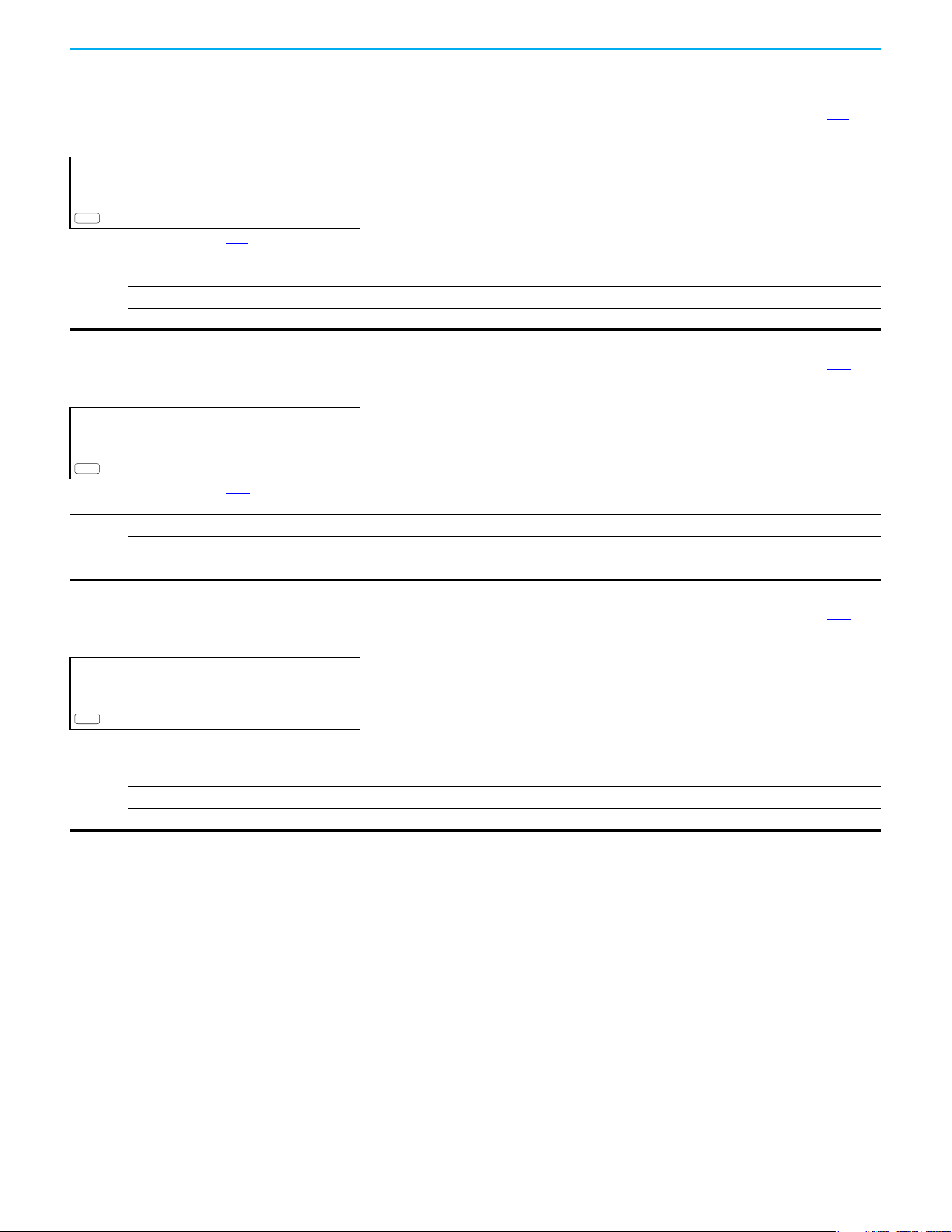
Rockwell Automation Publication 520-UM001N-EN-E - July 2024 145
Chapter 3 Programming and Parameters
Fault and Diagnostic Group (continued)
F631 [Fault 1 Freq]
F633 [Fault 3 Freq]
F635 [Fault 5 Freq]
F632 [Fault 2 Freq] Related Parameters: b001
F634 [Fault 4 Freq]
F636 [Fault 6 Freq]
F638 [Fault 8 Freq]
F640 [Fault10 Freq]
PowerFlex 525 only
F637 [Fault 7 Freq]
F639 [Fault 9 Freq]
Displays and stores the value of b001
[Output Freq] with the most recent 10 faults occurred.
[Fault 1 Freq] stores the most recent fault, [Fault 2 Freq] stores the second most recent fault and [Fault 3 Freq] stores the third most recent fault.
Values
Default: Read Only
Min/Max: 0.00/500.00 Hz
Display: 0.01 Hz
PF 525
F641 [Fault 1 Current]
F643 [Fault 3 Current]
F645 [Fault 5 Current]
F642 [Fault 2 Current] Related Parameters: b003
F644 [Fault 4 Current]
F646 [Fault 6 Current]
F648 [Fault 8 Current]
F650 [Fault10 Current]
PowerFlex 525 only
F647 [Fault 7 Current]
F649 [Fault 9 Current]
Displays and stores the value of b003
[Output Current] with the most recent 10 faults occurred.
[Fault 1 Current] stores the most recent fault, [Fault 2 Current] stores the second most recent fault and [Fault 3 Current] stores the third most recent fault.
Values
Default: Read Only
Min/Max: 0.00/(Drive Rated Amps x 2)
Display: 0.01 A
PF 525
F651 [Fault 1 BusVolts]
F653 [Fault 3 BusVolts]
F655 [Fault 5 BusVolts]
F652 [Fault 2 BusVolts] Related Parameters: b005
F654 [Fault 4 BusVolts]
F656 [Fault 6 BusVolts]
F658 [Fault 8 BusVolts]
F660 [Fault10 BusVolts]
PowerFlex 525 only
F657 [Fault 7 BusVolts]
F659 [Fault 9 BusVolts]
Displays and stores the value of b005
[DC Bus Voltage] with the most recent 10 faults occurred.
[Fault 1 BusVolts] stores the most recent fault, [Fault2 BusVolts] stores the second most recent fault and [Fault 3 BusVolts] stores the third most recent fault.
Values
Default: Read Only
Min/Max: 0/1200V DC
Display: 1V DC
PF 525
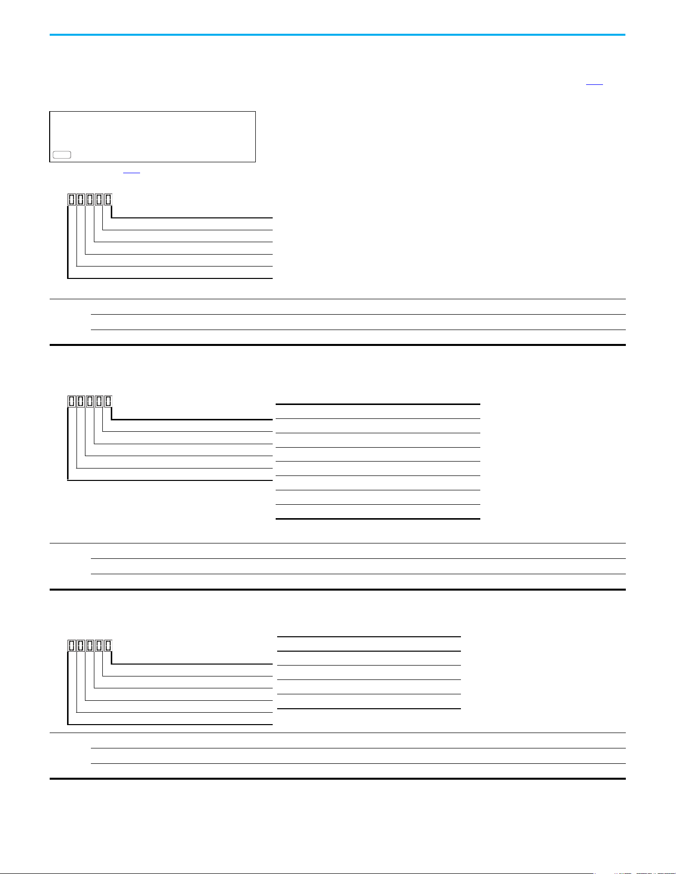
146 Rockwell Automation Publication 520-UM001N-EN-E - July 2024
Chapter 3 Programming and Parameters
Fault and Diagnostic Group (continued)
F661 [Status @ Fault 1]
F663 [Status @ Fault 3]
F665 [Status @ Fault 5]
F662 [Status @ Fault 2] Related Parameters: b006
F664 [Status @ Fault 4]
F666 [Status @ Fault 6]
F668 [Status @ Fault 8]
F670 [Status @ Fault10]
PowerFlex 525 only
F667 [Status @ Fault 7]
F669 [Status @ Fault 9]
Displays the value of b006
[Drive Status] with the most recent 10 faults occurred.
[Status @ Fault 1] stores the most recent fault, [Status @ Fault 2] stores the second most recent fault and [Status @ Fault 3] stores the third most recent fault.
Values
Default: Read Only
Min/Max: 0/0x1F
Display: 1
PF 525
1 = Condition True, 0 = Condition False
Running Digit 1
Forward Digit 2
Accelerating Digit 3
Decelerating Digit 4
SafetyActive
(1)
Digit 5
(1) Setting is specific to PowerFlex 525 drives only.
F681 [Comm Sts - DSI]
Displays the status of the RS-485 serial (DSI) port to the drive.
Values
Default: Read Only
Min/Max: 0000/1911
Display: 0000
1 = Condition True, 0 = Condition False
Rx Digit 1
Tx Digit 2
Status Digit 3
Error Digit 4
Not Used
Digit 3 (Connection Status)
0 “Not Active”
1 “Modbus slave network (external Modbus master)”
2 “Modbus multi-drive w/ internal com option master”
3 “Modbus multi-drive w/ embedded com master”
(1)
(1) Setting is specific to PowerFlex 525 drives only.
4 “DSI peripheral connected”
5…8 “Reserved”
9 “RS-485 network faulted”
F682 [Comm Sts - Opt]
Displays the status of the internal communication to the drive.
Values
Default: Read Only
Min/Max: 0000/1911
Display: 0000
1 = Condition True, 0 = Condition False
Rx Digit 1
Tx Digit 2
Status Digit 3
Error Digit 4
Not Used
Digit 3 = “Internal Com option”
0 “Not Active (no connection)”
1 “Internal option connected/active”
2…8 “Reserved”
9 “Internal com option faulted”
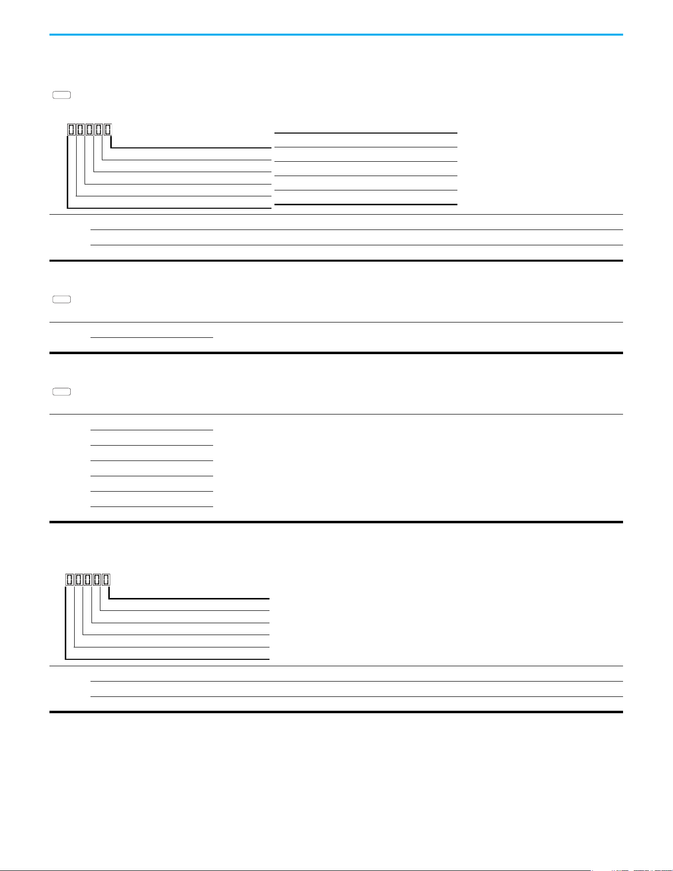
Rockwell Automation Publication 520-UM001N-EN-E - July 2024 147
Chapter 3 Programming and Parameters
Fault and Diagnostic Group (continued)
F683 [Com Sts-Emb Enet]
PowerFlex 525 only
Displays the status of the embedded EtherNet/IP interface to the drive.
Values
Default: Read Only
Min/Max: 0000/1911
Display: 0000
PF 525
1 = Condition True, 0 = Condition False
Rx Digit 1
Tx Digit 2
Status Digit 3
Error Digit 4
Not Used
Digit 3 = “Embedded EtherNet/IP”
0 “Not Active (no connection)”
1 “Embedded EtherNet/IP active”
2…8 “Reserved”
9 “Embedded EtherNet/IP faulted”
F684 [EN Addr Src]
PowerFlex 525 only
Displays the actual source of the Ethernet configuration (IP address, subnet mask, and gateway address).
Options
1 “Parameters”
Read Only
2“BOOTP”
PF 525
F685 [EN Rate Act]
PowerFlex 525 only
Displays the network data rate that is currently used by the embedded EtherNet/IP interface.
Options
0“No Link”
Read Only
1 “10Mbps Full”
2 “10Mbps Half”
3 “100Mbps Full”
4“100Mbps Half”
5 “Dup IP Addr”
6“Disabled”
PF 525
F686 [DSI I/O Act]
Displays the Drives that are active in Multi-Drive mode.
Value
Default: Read Only
Min/Max: 00000/11111
Display: 00000
1 = Drive Active, 0 = Drive Inactive
Drive 0 Actv Digit 1
Drive 1 Actv Digit 2
Drive 2 Actv Digit 3
Drive 3 Actv Digit 4
Drive 4 Actv Digit 5

148 Rockwell Automation Publication 520-UM001N-EN-E - July 2024
Chapter 3 Programming and Parameters
Fault and Diagnostic Group (continued)
F687 [HW Addr 1]
F688 [HW Addr 2]
F689 [HW Addr 3]
F690 [HW Addr 4]
F691 [HW Addr 5]
F692 [HW Addr 6]
PowerFlex 525 only
Shows the MAC address for the embedded EtherNet/IP interface.
Values
Default: Read Only
Min/Max: 0/255
Display: 1
PF 525
F693 [EN IP Addr Act 1]
F694 [EN IP Addr Act 2]
F695 [EN IP Addr Act 3]
F696 [EN IP Addr Act 4]
PowerFlex 525 only
Shows the actual IP address that is used by the embedded EtherNet/IP interface at the time. This indicates 0 if no address is set.
Values
Default: Read Only
Min/Max: 0/255
Display: 1
PF 525
255.255.255.255
[EN IP Addr Act 1]
[EN IP Addr Act 2]
[EN IP Addr Act 3]
[EN IP Addr Act 4]
F697 [EN Subnet Act 1]
F698 [EN Subnet Act 2]
F699 [EN Subnet Act 3]
F700 [EN Subnet Act 4]
PowerFlex 525 only
Shows the actual subnet mask that is used by the embedded EtherNet/IP interface at the time. This indicates 0 if no address is set.
Values
Default: Read Only
Min/Max: 0/255
Display: 1
PF 525
255.255.255.255
[EN Subnet Act 1]
[EN Subnet Act 2]
[EN Subnet Act 3]
[EN Subnet Act 4]

Rockwell Automation Publication 520-UM001N-EN-E - July 2024 149
Chapter 3 Programming and Parameters
Fault and Diagnostic Group (continued)
F701 [EN Gateway Act 1]
F702 [EN Gateway Act 2]
F703 [EN Gateway Act 3]
F704 [EN Gateway Act 4]
PowerFlex 525 only
Shows the actual gateway address that is used by the embedded EtherNet/IP interface at the time. This indicates 0 if no address is set.
Values
Default: Read Only
Min/Max: 0/255
Display: 1
PF 525
255.255.255.255
[EN Gateway Act 1]
[EN Gateway Act 2]
[EN Gateway Act 3]
[EN Gateway Act 4]
F705 [Drv 0 Logic Cmd]
F709 [Drv 1 Logic Cmd]
F713 [Drv 2 Logic Cmd]
F717 [Drv 3 Logic Cmd]
F721 [Drv 4 Logic Cmd]
In multi-drive mode, this is the logic command being transmitted to drive 0/1/2/3/4/.
In single-drive mode, this is the logic command being used by the drive (whether HS-DSI, EtherNet/IP, or DSI) at the time. If comms control is NOT being used, and the drive
is in single-drive mode, then this parameter shows 0.
Values
Default: Read Only
Min/Max: 0/FFFF
Display: 1
F706 [Drv 0 Reference]
F710 [Drv 1 Reference]
F714 [Drv 2 Reference]
F718 [Drv 3 Reference]
F722 [Drv 4 Reference]
In multi-drive mode, this is the reference being transmitted to drive 0/1/2/3/4.
In single-drive mode, this is the reference being used by the drive (whether HS-DSI, EtherNet/IP, or DSI) at the time. If comms control is NOT being used, and the drive is in
single-drive mode, then this parameter shows 0.
Values
Default: Read Only
Min/Max: 0.00/5000.00 Hz
Display: 0.01 Hz
F707 [Drv 0 Logic Sts]
F711 [Drv 1 Logic Sts]
F715 [Drv 2 Logic Sts]
F719 [Drv 3 Logic Sts]
F723 [Drv 4 Logic Sts]
In multi-drive mode, this is the logic status being received from drive 0/1/2/3/4.
In single-drive mode, this is the logic status of the drive at the time.
Values
Default: Read Only
Min/Max: 0/FFFF
Display: 1

150 Rockwell Automation Publication 520-UM001N-EN-E - July 2024
Chapter 3 Programming and Parameters
Fault and Diagnostic Group (continued)
F708 [Drv 0 Feedback]
F712 [Drv 1 Feedback]
F716 [Drv 2 Feedback]
F720 [Drv 3 Feedback]
F724 [Drv 4 Feedback]
In multi-drive mode, this is the feedback being received from drive 0/1/2/3/4.
In single-drive mode, this is the feedback of the drive at the time.
Values
Default: Read Only
Min/Max: 0.00/5000.00 Hz
Display: 0.01 Hz
F725 [EN Rx Overruns]
PowerFlex 525 only
A count of the number of receive overrun errors reported by the embedded EtherNet/IP interface.
Values
Default: Read Only
Min/Max: 0/65535
Display: 1
PF 525
F726 [EN Rx Packets]
PowerFlex 525 only
A count of the number of receive packets that are reported by the embedded EtherNet/IP interface.
Values
Default: Read Only
Min/Max: 0/65535
Display: 1
PF 525
F727 [EN Rx Errors]
PowerFlex 525 only
A count of the number of receive errors that are reported by the embedded EtherNet/IP interface.
Values
Default: Read Only
Min/Max: 0/65535
Display: 1
PF 525
F728 [EN Tx Packets]
PowerFlex 525 only
A count of the number of transmitted packets reported by the embedded EtherNet/IP interface.
Values
Default: Read Only
Min/Max: 0/65535
Display: 1
PF 525
F729 [EN Tx Errors]
PowerFlex 525 only
A count of the number of transmit errors reported by the embedded EtherNet/IP interface.
Values
Default: Read Only
Min/Max: 0/65535
Display: 1
PF 525

Rockwell Automation Publication 520-UM001N-EN-E - July 2024 151
Chapter 3 Programming and Parameters
Fault and Diagnostic Group (continued)
F730 [EN Missed IO Pkt]
PowerFlex 525 only
The number of I/O packets missed.
Values
Default: Read Only
Min/Max: 0/65535
Display: 1
PF 525
F731 [DSI Errors]
The number of total DSI errors.
Values
Default: Read Only
Min/Max: 0/65535
Display: 1
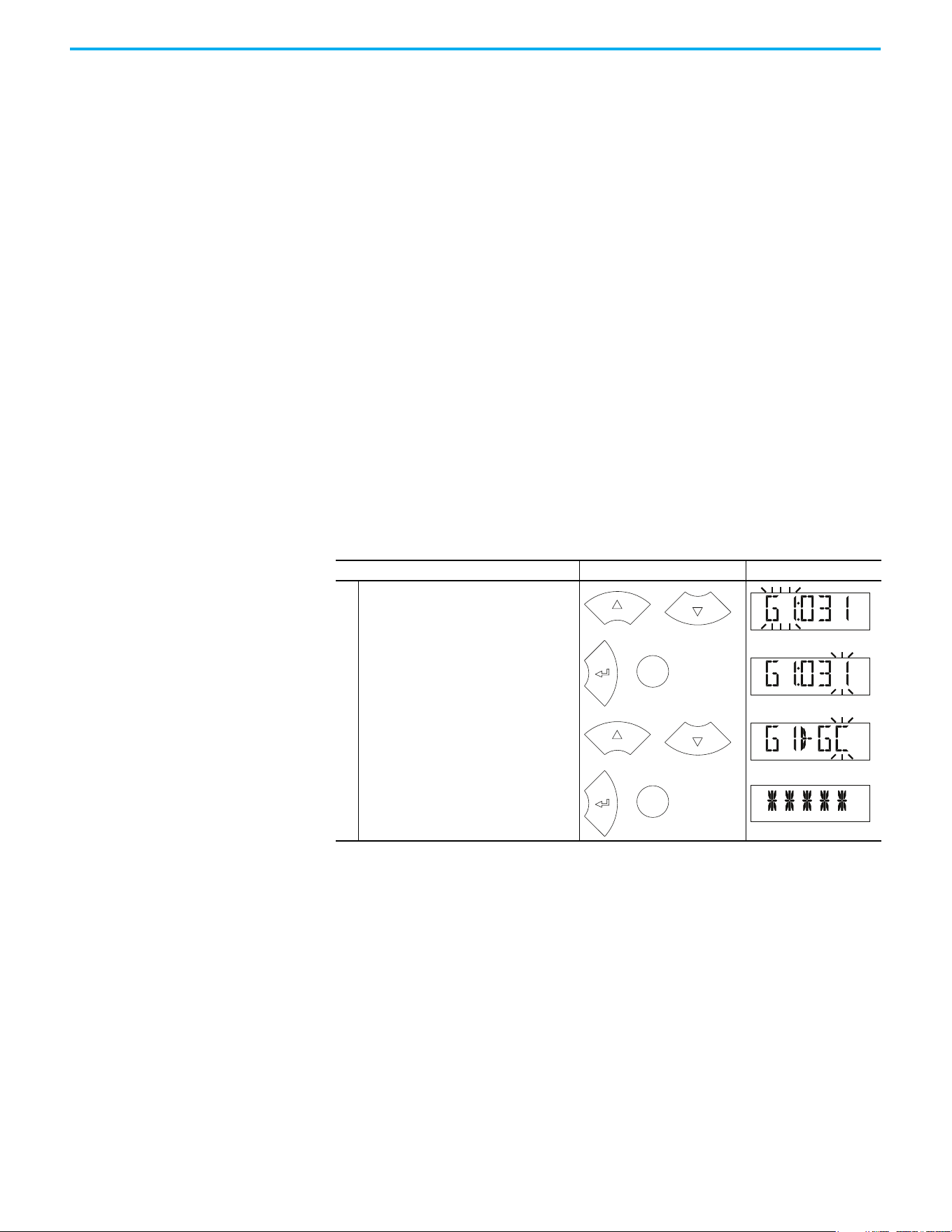
152 Rockwell Automation Publication 520-UM001N-EN-E - July 2024
Chapter 3 Programming and Parameters
AppView Parameter Groups AppView parameter groups provide a simple starting point for using the
PowerFlex 520-series drives by grouping certain commonly used parameters
based on different types of applications. Use these parameter groups to quickly
and easily set up the PowerFlex 520-series drive for your application.
AppView parameter groups are available for the following applications:
•Conveyor
•Mixer
• Compressor
•Centrifugal Pump
•Blower/Fan
•Extruder
• Positioning (PowerFlex 525 only)
• Textile/Fiber
You cannot add or remove parameters to or from the AppView parameter
groups. If you require quick access to additional parameters to what is already
included in the different AppView parameter groups, use the CustomView
parameter group instead.
The parameters in the AppView parameter groups can be quickly added to the
CustomView parameter group by doing the following:
Step Keys Example Displays
1.
Press the Up Arrow or Down Arrow to scroll to
an AppView group (G1…G8).
2.
Press Enter or Sel to enter a group. The
rightmost digit of the last viewed parameter
in that group flashes.
3.
Press the Up Arrow or Down Arrow to scroll to
the command G1->GC.
4.
Press Enter or Sel to add all parameters in
this AppView group to the CustomView group.
The LCD display shows a confirmation.
or
F
W
D
Sel
or
F
W
D
or
F
W
D
Sel
or
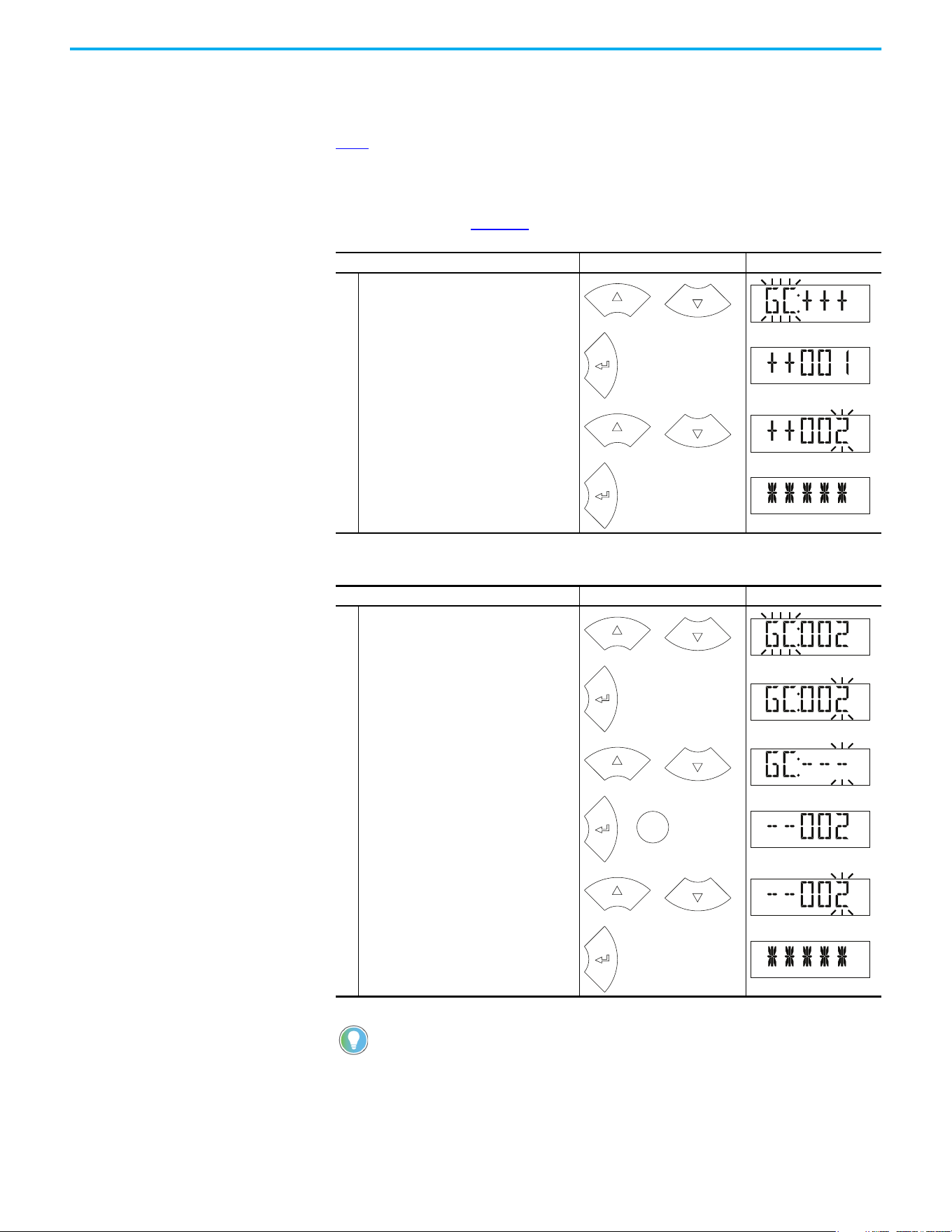
Rockwell Automation Publication 520-UM001N-EN-E - July 2024 153
Chapter 3 Programming and Parameters
CustomView Parameter
Group
CustomView allows you to quickly access only the parameters that are needed
for your application by storing them in a custom parameter group. Add your
frequently used parameters to this group, then hide all other parameters with
A552
[Program Lock] to simplify your drive configuration process.
Up to 100 parameters can be stored in the CustomView parameter group. You
can copy one entire AppView parameter group to the CustomView parameter
group as shown on page 152
or add individual parameters as show below.
To delete parameters from the CustomView parameter group:
Step Keys Example Displays
1.
Press the Up Arrow or Down Arrow to scroll to
the CustomView group (GC).
2.
Press Enter to view the parameters that can
be added to the CustomView group.
3.
Press the Up Arrow or Down Arrow to scroll
through the list of parameters.
4.
Press Enter to add the parameter to the
CustomView group. The LCD display shows a
confirmation.
Step Keys Example Displays
1.
Press the Up Arrow or Down Arrow to scroll to
the CustomView group (GC).
2.
Press Enter to view the parameters that are
in the CustomView group.
3.
Press the Up Arrow or Down Arrow to scroll to
the command GC---.
4.
Press Enter or Sel to view the parameters
that are stored in the CustomView group.
5.
Press the Up Arrow or Down Arrow to scroll
through the list of parameters.
6.
Press Enter to delete the parameter from the
CustomView group. The LCD display shows a
confirmation.
The Connected Components Workbench software can be used to speed
up this process with drag-and-drop functionality.
or
F
W
D
F
W
D
or
PROGR
A
M
F
W
D
or
F
W
D
F
W
D
or
F
W
D
Sel
or
F
W
D
or
PROGR
A
M
F
W
D

154 Rockwell Automation Publication 520-UM001N-EN-E - July 2024
Chapter 3 Programming and Parameters
Parameter Cross-reference by Name
Parameters
Parameter Name No. Parameter Name No. Parameter Name No.
10V Bipolar Enbl
(1)
093
Current Loop BW
(1)(2)
580 Drv 4 Logic Sts 723
2-Wire Mode 064 DB Resistor Sel 437 Drv 4 Reference 722
Accel Time 1 041 DB Threshold 438 Drv Ambient Sel 554
Accel Time 2 442 DC Brake Level 435 DSI Errors 731
Accel Time 3 444 DC Brake Time 434 DSI I/O Act 686
Accel Time 4 446 DC Brk Time@Strt 436 DSI I/O Cfg 175
Accum CO2 Sav 026 DC Bus Ripple 380 Elapsed kWh 021
Accum Cost Sav 025 DC Bus Voltage 005 Elapsed MWh 022
Accum kWh Sav 024 Decel Time 1 042 Elapsed Run Time 019
Analog In 0-10V 360 Decel Time 2 443 Elapsed Time-hr 362
Analog In 4-20mA 361 Decel Time 3 445 Elapsed Time-min 363
Analog In Filter 099 Decel Time 4 447 EM Brk Off Delay 086
Analog Out High
(3)
089 Dig In Status 014 EM Brk On Delay 087
Analog Out Sel
(2)
088
Dig Out Status
(2)(3)
394
EN Addr Sel
(1)
128
Anlg In 0-10V Hi 092 DigIn TermBlk 02 062
EN Addr Src
(1)
684
Anlg In 0-10V Lo 091 DigIn TermBlk 03 063
EN Comm Flt Actn
(1)
143
Anlg In mA Loss 097 DigIn TermBlk 05 065
EN Data In 1
(1)
153
Anlg In V Loss 094 DigIn TermBlk 06 066
EN Data In 2
(1)
154
Anlg In4-20mA Hi 096
DigIn TermBlk 07
(1)
067
EN Data In 3
(1)
155
Anlg In4-20mA Lo 095
DigIn TermBlk 08
(1)
068
EN Data In 4
(1)
156
Anlg Loss Delay 098 Drive OL Mode 495
EN Data Out 1
(1)
157
Anlg Out Setpt
(2)
090 Drive Status 006
EN Data Out 2
(1)
158
Auto Rstrt Delay 542
Drive Status 2
(2)(3)
393
EN Data Out 3
(1)
159
Auto Rstrt Tries 541 Drive Temp 027
EN Data Out 4
(1)
160
Autotune 040 Drive Type 367
EN Flt Cfg DL 1
(1)
147
Average kWh Cost 052
Droop Hertz@ FLA
(1)
441
EN Flt Cfg DL 2
(1)
148
Average Power 020 Drv 0 Feedback 708
EN Flt Cfg DL 3
(1)
149
Boost Select 530 Drv 0 Logic Cmd 705
EN Flt Cfg DL 4
(1)
150
Break Frequency 533 Drv 0 Logic Sts 707
EN Flt Cfg Logic
(1)
145
Break Voltage 532 Drv 0 Reference 706
EN Flt Cfg Ref
(1)
146
Bus Reg Enable 550 Drv 1 Addr 171
EN Gateway Act 1
(1)
701
Cmd Stat Select
(1)
122 Drv 1 Feedback 712
EN Gateway Act 2
(1)
702
Com Sts-Emb Enet
(1)
683 Drv 1 Logic Cmd 709
EN Gateway Act 3
(1)
703
Comm Loss Action 125 Drv 1 Logic Sts 711
EN Gateway Act 4
(1)
704
Comm Loss Time 126 Drv 1 Reference 710
EN Gateway Cfg 1
(1)
137
Comm Sts - DSI 681 Drv 2 Addr 172
EN Gateway Cfg 2
(1)
138
Comm Sts - Opt 682 Drv 2 Feedback 716
EN Gateway Cfg 3
(1)
139
Comm Write Mode 121 Drv 2 Logic Cmd 713
EN Gateway Cfg 4
(1)
140
Commanded Freq 002 Drv 2 Logic Sts 715
EN Idle Flt Actn
(1)
144
Compensation 547 Drv 2 Reference 714
EN IP Addr Act 1
(1)
693
Contrl In Status 013 Drv 3 Addr 173
EN IP Addr Act 2
(1)
694
Control Source 012 Drv 3 Feedback 720
EN IP Addr Act 3
(1)
695
Control SW Ver 029 Drv 3 Logic Cmd 717
EN IP Addr Act 4
(1)
696

Rockwell Automation Publication 520-UM001N-EN-E - July 2024 155
Chapter 3 Programming and Parameters
Control Temp 028 Drv 3 Logic Sts 719
EN IP Addr Cfg 1
(1)
129
Counter Status 364 Drv 3 Reference 718
EN IP Addr Cfg 2
(1)
130
Counts Per Unit
(1)
559 Drv 4 Addr 174
EN IP Addr Cfg 3
(1)
131
Current Limit 1 484 Drv 4 Feedback 724
EN IP Addr Cfg 4
(1)
132
Current Limit 2
(1)
485 Drv 4 Logic Cmd 721
EN Missed IO Pkt
(1)
730
EN Rate Act
(1)
685
Fault 6 BusVolts
(1)
656 Half Bus Enable 549
EN Rate Cfg
(1)
141
Fault 6 Code
(1)
606
Home Save
(1)
561
EN Rx Errors
(1)
727
Fault 6 Current
(1)
646
HW Addr 1
(1)
687
EN Rx Overruns
(1)
725
Fault 6 Freq
(1)
636
HW Addr 2
(1)
688
EN Rx Packets
(1)
726
Fault 6 Time-hr
(1)
616
HW Addr 3
(1)
689
EN Subnet Act 1
(1)
697
Fault 6 Time-min
(1)
626
HW Addr 4
(1)
690
EN Subnet Act 2
(1)
698
Fault 7 BusVolts
(1)
657
HW Addr 5
(1)
691
EN Subnet Act 3
(1)
699
Fault 7 Code
(1)
607
HW Addr 6
(1)
692
EN Subnet Act 4
(1)
700
Fault 7 Current
(1)
647 IR Voltage Drop 496
EN Subnet Cfg 1
(1)
133
Fault 7 Freq
(1)
637 Jog Accel/Decel 432
EN Subnet Cfg 2
(1)
134
Fault 7 Time-hr
(1)
617 Jog Frequency 431
EN Subnet Cfg 3
(1)
135
Fault 7 Time-min
(1)
627 Keypad Freq 426
EN Subnet Cfg 4
(1)
136
Fault 8 BusVolts
(1)
658
Ki Speed Loop
(2)
538
EN Tx Errors
(1)
729
Fault 8 Code
(1)
608
Kp Speed Loop
(2)
539
EN Tx Packets
(1)
728
Fault 8 Current
(1)
648 Language 30
Encoder Pos Tol
(1)
564
Fault 8 Freq
(1)
638
Load Loss Level
(1)
490
Encoder PPR
(1)
536
Fault 8 Time-hr
(1)
618
Load Loss Time
(1)
491
Encoder Speed
(2)
378
Fault 8 Time-min
(1)
628 Max Traverse 567
Energy Saved 023
Fault 9 BusVolts
(1)
659 Maximum Freq 044
Enh Control Word
(1)
560
Fault 9 Code
(1)
609 Maximum Voltage 534
Fault 1 BusVolts 651
Fault 9 Current
(1)
649 Minimum Freq 043
Fault 1 Code 007
Fault 9 Freq
(1)
639 MOP Freq 427
Fault 1 Current 641
Fault 9 Time-hr
(1)
619 MOP Preload 429
Fault 1 Freq 631
Fault 9 Time-min
(1)
629 MOP Reset Sel 428
Fault 1 Time-hr 611 Fault Clear 551 MOP Time 430
Fault 1 Time-min 621
Fault10 BusVolts
(1)
660
Motor Fdbk Type
(2)
535
Fault 2 BusVolts 652
Fault10 Code
(1)
610
Motor Lm
(1)
499
Fault 2 Code 008
Fault10 Current
(1)
650
Motor Lx
(1)
500
Fault 2 Current 642
Fault10 Freq
(1)
640 Motor NP FLA 034
Fault 2 Freq 632
Fault10 Time-hr
(1)
620 Motor NP Hertz 032
Fault 2 Time-hr 612
Fault10 Time-min
(1)
630 Motor NP Poles 035
Fault 2 Time-min 622 Fiber Status 390
Motor NP Power
(1)
037
Fault 3 BusVolts 653
Find Home Dir
(1)
563 Motor NP RPM 036
Fault 3 Code 009
Find Home Freq
(1)
562 Motor NP Volts 031
Fault 3 Current 643
Flux Braking En
(2)(3)
575 Motor OL Current 033
Fault 3 Freq 633 Flux Current Ref 497 Motor OL Level 369
Fault 3 Time-hr 613 Flying Start En 545 Motor OL Ret 494
Fault 3 Time-min 623 FlyStrt CurLimit 546 Motor OL Select 493
Fault 4 BusVolts 654
Freq 1
(1)
510
Motor Rr
(1)
498
Parameters (Continued)
Parameter Name No. Parameter Name No. Parameter Name No.

156 Rockwell Automation Publication 520-UM001N-EN-E - July 2024
Chapter 3 Programming and Parameters
Fault 4 Code 604
Freq 1 BW
(1)
511
Mtr Options Cfg
(2)(4)
573
Fault 4 Current 644
Freq 1 Ki
(1)
522 MultiDrv Sel 169
Fault 4 Freq 634
Freq 1 Kp
(1)
521 Opt Data In 1 161
Fault 4 Time-hr 614
Freq 2
(1)
512 Opt Data In 2 162
Fault 4 Time-min 624
Freq 2 BW
(1)
513 Opt Data In 3 163
Fault 5 BusVolts 655
Freq 2 Ki
(1)
524 Opt Data In 4 164
Fault 5 Code 605
Freq 2 Kp
(1)
523 Opt Data Out 1 165
Fault 5 Current 645
Freq 3
(1)
514 Opt Data Out 2 166
Fault 5 Freq 635
Freq 3 BW
(1)
515 Opt Data Out 3 167
Fault 5 Time-hr 615
Freq 3 Ki
(1)
526 Opt Data Out 4 168
Fault 5 Time-min 625
Freq 3 Kp
(1)
525
Opto Out Logic
(1)
075
Opto Out1 Level
(1)
070
PM FWKn 1 Kp
(1)(3)
527
Relay 2 On Time
(1)
084
Opto Out1 Sel
(1)
069
PM FWKn 2 Kp
(1)(3)
528
Relay Out2 Level
(1)
082
Opto Out2 Level
(1)
073
PM HIFI NS Cur
(1)(3)
519
Relay Out2 Sel
(1)
081
Opto Out2 Sel
(1)
072
PM Initial Sel
(1)(3)
516 Reset Meters 555
Out Phas Loss En 557
PM IR Voltage
(1)(3)
501 Reset to Defalts 053
Output Current 003
PM IXd Voltage
(1)(3)
502 Reverse Disable 544
Output Freq 001
PM IXq Voltage
(1)(3)
503 RS485 Data Rate 123
Output Power 017
PM Stable 1 Freq
(1)(3)
581 RS485 Format 127
Output Powr Fctr 381
PM Stable 1 Kp
(1)(3)
583 RS485 Node Addr 124
Output RPM 015
PM Stable 2 Freq
(1)(3)
582 S Curve % 439
Output Speed 016
PM Stable 2 Kp
(1)(3)
584
Safety Open En
(1)
105
Output Voltage 004
PM Stable Brk Pt
(1)(3)
585
SafetyFlt RstCfg
(1)(3)
106
P Jump 570
PM Stepload Kp
(1)(3)
586 Shear Pin 1 Time 487
Phase Loss Level
(2)(3)
576
Pos Reg Filter
(1)
565 Shear Pin1 Level 486
PID 1 Deadband 465
Pos Reg Gain
(1)
566
Shear Pin 2 Time
(1)
489
PID 1 Diff Rate 463
Position Status
(1)
387
Shear Pin2 Level
(1)
488
PID 1 Fdback Sel 460
Positioning Mode
(1)
558 Skip Freq Band 1 449
PID 1 Integ Time 462 Power Loss Mode 548 Skip Freq Band 2 451
PID 1 Invert Err 467 Power Saved 018
Skip Freq Band 3
(1)
453
PID 1 Preload 466 Preset Freq 0 410
Skip Freq Band 4
(1)
455
PID 1 Prop Gain 461 Preset Freq 1 411 Skip Frequency 1 448
PID 1 Ref Sel 459 Preset Freq 2 412 Skip Frequency 2 450
PID 1 Setpoint 464 Preset Freq 3 413
Skip Frequency 3
(1)
452
PID 1 Trim Hi 456 Preset Freq 4 414
Skip Frequency 4
(1)
454
PID 1 Trim Lo 457 Preset Freq 5 415 Sleep Level 101
PID 1 Trim Sel 458 Preset Freq 6 416 Sleep Time 102
PID1 Fdbk Displ 383 Preset Freq 7 417 Sleep-Wake Sel 100
PID1 Setpnt Disp 384
Preset Freq 8
(1)
418 Slip Hz Meter 375
PID 2 Deadband
(1)
477
Preset Freq 9
(1)
419 Speed Feedback 376
PID 2 Diff Rate
(1)
475
Preset Freq 10
(1)
420 Speed Ratio 572
PID 2 Fdback Sel
(1)
472
Preset Freq 11
(1)
421 Speed Reference1 047
PID 2 Integ Time
(1)
474
Preset Freq 12
(1)
422 Speed Reference2 049
PID 2 Invert Err
(1)
479
Preset Freq 13
(1)
423 Speed Reference3 051
Parameters (Continued)
Parameter Name No. Parameter Name No. Parameter Name No.

Rockwell Automation Publication 520-UM001N-EN-E - July 2024 157
Chapter 3 Programming and Parameters
PID 2 Preload
(1)
478
Preset Freq 14
(1)
424
Speed Reg Sel
(1)
509
PID 2 Prop Gain
(1)
473
Preset Freq 15
(1)
425 Stall Fault Time 492
PID 2 Ref Sel
(1)
471 Process Disp Hi 482 Start At PowerUp 543
PID 2 Setpoint
(1)
476 Process Disp Lo 481 Start Boost 531
PID 2 Trim Hi
(1)
468 Process Display 010 Start Source 1 046
PID 2 Trim Lo
(1)
469 Program Lock 552 Start Source 2 048
PID 2 Trim Sel
(1)
470 Program Lock Mod 553 Start Source 3 050
PID2 Fdbk Displ
(1)
385 Pulse In Scale 537 Status @ Fault 1 661
PID2 Setpnt Disp
(1)
386 Purge Frequency 433 Status @ Fault 2 662
PM 1 Efficiency
(1)(3)
587 PWM Frequency 440 Status @ Fault 3 663
PM 2 Efficiency
(1)(3)
588
RdyBit Mode Act
(2)(5)
392 Status @ Fault 4 664
PM Algor Sel
(1)(3)
589
RdyBit Mode Cfg
(2)(4)
574 Status @ Fault 5 665
PM Align Time
(1)(3)
518 Relay 1 Off Time 080
Status @ Fault 6
(1)
666
PM BEMF Voltage
(1)(3)
504 Relay 1 On Time 079
Status @ Fault 7
(1)
667
PM Bus Reg Kd
(1)(3)
520 Relay Out1 Level 077
Status @ Fault 8
(1)
668
PM Control Cfg
(1)(3)
529 Relay Out1 Sel 076
Status @ Fault 9
(1)
669
PM DC Inject Cur
(1)(3)
517
Relay 2 Off Time
(1)
085
Status @ Fault10
(1)
670
Step Units 0
(1)
200
Stp Logic Status
(1)
391 Testpoint Sel 483
Step Units 1
(1)
202
Stp Logic Time 0
(1)
190 Text Scroll 556
Step Units 2
(1)
204
Stp Logic Time 1
(1)
191 Testpoint Data 368
Step Units 3
(1)
206
Stp Logic Time 2
(1)
192 Timer Status 365
Step Units 4
(1)
208
Stp Logic Time 3
(1)
193 Timer StatusF 366
Step Units 5
(1)
210
Stp Logic Time 4
(1)
194 Torque Current 382
Step Units 6
(1)
212
Stp Logic Time 5
(1)
195 Torque Perf Mode 039
Step Units 7
(1)
214
Stp Logic Time 6
(1)
196 Traverse Dec 569
Stop Mode 045
Stp Logic Time 7
(1)
197 Traverse Inc 568
Stp Logic 0
(1)
180 Sync Time 571
Units Traveled H
(1)
388
Stp Logic 1
(1)
181 SynRM SW Freq 590
Units Traveled L
(1)
389
Stp Logic 2
(1)
182 SynRM Flux Cur 591 Var PWM Disable 540
Stp Logic 3
(1)
183 SynRM Freq1 Volt 592 Voltage Class 038
Stp Logic 4
(1)
184 SynRM Freq1 Kp 593 Wake Level 103
Stp Logic 5
(1)
185 SynRM Freq1 Comp 594 Wake Time 104
Stp Logic 6
(1)
186 SynRM Freq2 BW 595
Stp Logic 7
(1)
187 SynRM Freq2 Kp 596
(1) Parameter is specific to PowerFlex 525 drives only.
(2) Parameter is available in PowerFlex 525 FRN 5.xxx and later.
(3) Parameter is also available in PowerFlex 523 FRN 3.xxx and later.
(4) Parameter is available in PowerFlex 525 FRN 2.xxx and later.
(5) Parameter is available in PowerFlex 525 FRN 3.xxx and later.
Parameters (Continued)
Parameter Name No. Parameter Name No. Parameter Name No.

158 Rockwell Automation Publication 520-UM001N-EN-E - July 2024
Chapter 3 Programming and Parameters
Notes:
Rockwell Automation Publication 520-UM001N-EN-E - July 2024 159
Chapter 4
Troubleshooting
This chapter provides information to guide you in troubleshooting the
PowerFlex 520-series drive. Included is a listing and description of drive faults
with possible solutions, when applicable.
Drive Status The condition or state of your drive is constantly monitored. Any changes are
indicated through the integral LCD display.
See Display and Control Keys on page 61
for information on drive status
indicators and controls.
Faults A fault is a condition that stops the drive. There are two fault types.
ATTENTION: Risk of injury or equipment damage exists. Drive does not
contain user-serviceable components. Do not disassemble drive chassis.
Fault Types
Type Fault Description
1 Auto-Reset/Run
When this type of fault occurs, and A541
[Auto Rstrt Tries] is set to a value greater
than “0,” a user-configurable timer, A542 [Auto Rstrt Delay], begins. When the timer
reaches zero, the drive attempts to automatically reset the fault. If the condition that
caused the fault is no longer present, the fault is reset and the drive is restarted.
2 Non-Resettable
This type of fault may require drive or motor repair, or is caused by wiring or
programming errors. The cause of the fault must be corrected before the fault can
be cleared.
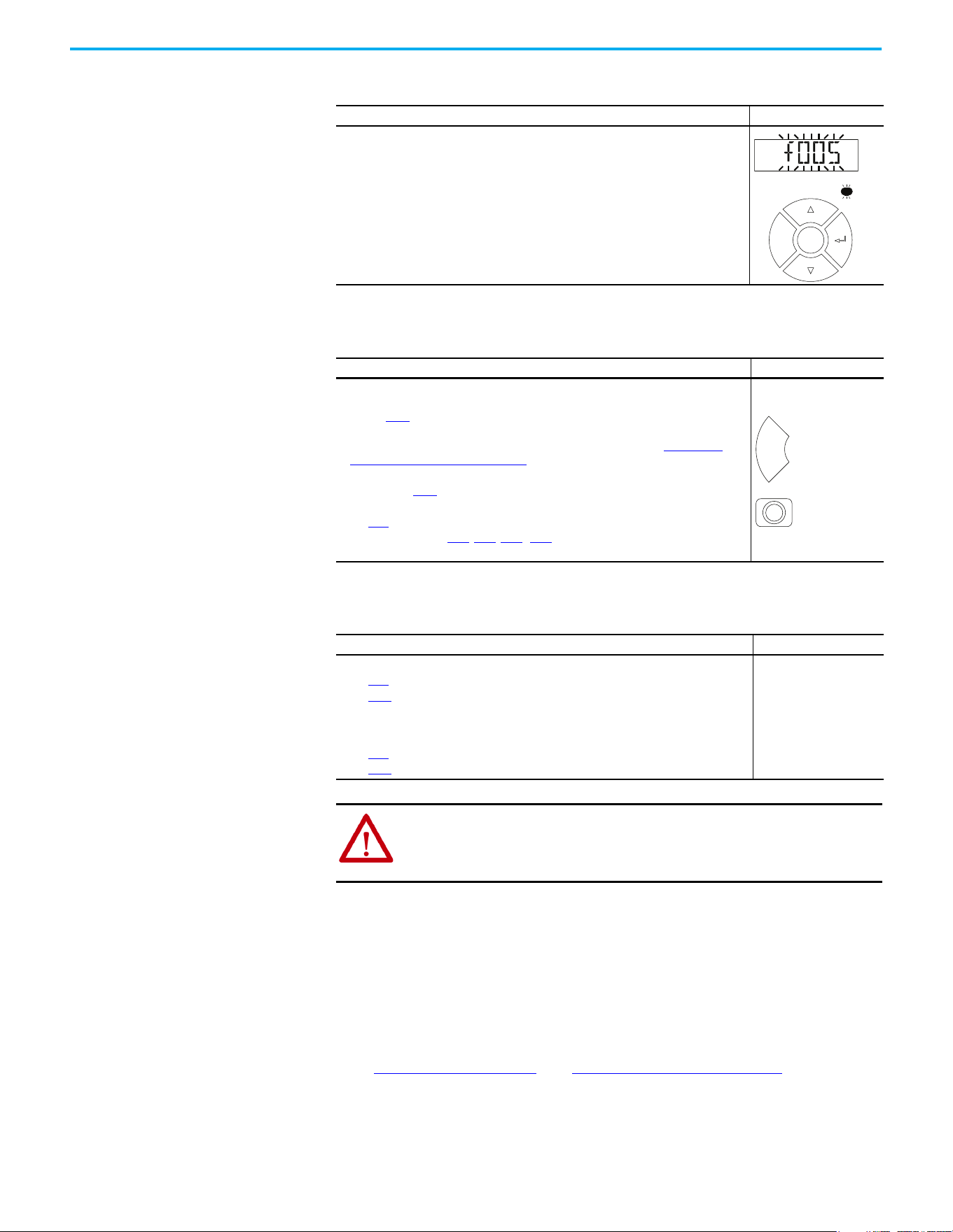
160 Rockwell Automation Publication 520-UM001N-EN-E - July 2024
Chapter 4 Troubleshooting
Fault Indication
Manually Clearing Faults
Automatically Clearing Faults
Auto Restart (Reset/Run)
The Auto Restart feature provides the ability for the drive to automatically
perform a fault reset followed by a start attempt without user or application
intervention. This allows remote or “unattended” operation. Only certain
faults are allowed to be reset. Certain faults (Type 2) that indicate possible
drive component malfunction are not resettable. Fault types are listed in the
table Fault Types on page 159
. See Fault Descriptions on page 161 for more
information.
Use caution when enabling this feature, since the drive attempts to issue its
own start command based on user selected programming.
Condition Display
Drive is indicating a fault.
The integral LCD display provides visual notification of a fault condition by displaying
the following.
• Flashing fault number
• Flashing fault indicator (LED)
Press the Esc key to regain control of the display.
Step Keys
1. Press Esc to acknowledge the fault. The fault information is removed so that you
can use the integral keypad.
Access b007
[Fault 1 Code] to view the most recent fault information.
2. Address the condition that caused the fault.
The cause must be corrected before the fault can be cleared. See Fault Types,
Descriptions, and Actions on page 161.
3. After corrective action has been taken, clear the fault by one of these methods.
• Press Stop if P045
[Stop Mode] is set to a value between “0” and “3”.
• Cycle drive power.
•Set A551 [Fault Clear] to 1 “Reset Fault” or 2 “Clear Buffer”.
• Cycle digital input if t062
, t063, t065...t068 [DigIn TermBlk xx] is set to 13 “Clear
Fault”.
Option/Step
Clear a Type 1 fault and restart the drive.
1. Set A541
[Auto Rstrt Tries] to a value other than “0”.
2. Set A542
[Auto Rstrt Delay] to a value other than “0”.
Clear an OverVoltage, UnderVoltage, or Heatsink OvrTmp fault
without restarting the drive.
1. Set A541
[Auto Rstrt Tries] to a value other than “0”.
2. Set A542
[Auto Rstrt Delay] to “0”.
ATTENTION: Equipment damage and/or personal injury may result if these
parameters are used in an inappropriate application. Do not use this
function without considering applicable local, national, and international
codes, standards, regulations or industry guidelines.
FAULT
F
W
D
Esc
Sel
Esc
Rockwell Automation Publication 520-UM001N-EN-E - July 2024 161
Chapter 4 Troubleshooting
Fault Descriptions
Fault Types, Descriptions, and Actions
No. Fault
Type
(1)
Description Action
F000 No Fault — No fault present. —
F002 Auxiliary Input 1 External trip (Auxiliary) input.
• Check remote wiring.
• Verify communications
programming for intentional fault.
F003 Power Loss 2
Single-phase operation detected
with excessive load.
• Monitor the incoming AC line for low
voltage or line power interruption.
• Check input fuses.
•Reduce load.
F004 UnderVoltage 1
DC bus voltage fell below the min
value.
Monitor the incoming AC line for low
voltage or line power interruption.
F005 OverVoltage 1
DC bus voltage exceeded max
value.
Monitor the AC line for high line voltage
or transient conditions. Bus
overvoltage can also be caused by
motor regeneration. Extend the decel
time or install dynamic brake option.
F006 Motor Stalled 1
Drive is unable to accelerate or
decelerate motor.
•Increase P041
, A442, A444, A446
[Accel Time x] or reduce load so
drive output current does not exceed
the current set by parameter A484,
A485 [Current Limit x] for too long.
• Check for overhauling load.
F007 Motor Overload 1 Internal electronic overload trip.
• An excessive motor load exists.
Reduce load so drive output current
does not exceed the current set by
parameter P033
[Motor OL Current].
• Verify A530
[Boost Select] setting.
F008 Heatsink OvrTmp 1
Heatsink/Power Module
temperature exceeds a
predefined value.
• Check for blocked or dirty heatsink
fins. Verify that ambient temperature
has not exceeded the rated ambient
temperature.
•Check fan.
F009 CC OvrTmp 1
Control module temperature
exceeds a predefined value.
• Check product ambient temperature.
• Check for airflow obstruction.
• Check for dirt or debris.
•Check fan.
F012 HW OverCurrent 2
The drive output current has
exceeded the hardware current
limit.
Check programming. Check for excess
load, improper A530
[Boost Select]
setting, DC brake volts set too high or
other causes of excess current.
F013 Ground Fault
1
(2)
A current path to earth ground has
been detected at one or more of
the drive output terminals.
Check the motor and external wiring to
the drive output terminals for a
grounded condition.
F015
(3)
Load Loss 2
The output torque current is below
the value that is programmed in
A490 [Load Loss Level] for a time
period greater than the time
programmed in A491 [Load Loss
Time].
• Verify connections between motor
and load.
• Verify level and time requirements.
F021 Output Ph Loss 1
Output Phase Loss (if enabled).
Configure with A557
[Out Phas
Loss En].
• Verify motor wiring.
• Verify motor.
F029 Analog In Loss 1
An analog input is configured to
fault on signal loss. A signal loss
has occurred.
Configure with t094
[Anlg In V
Loss] or t097 [Anlg In mA Loss].
• Check for broken/loose connections
at inputs.
• Check parameters.
F033 Auto Rstrt Tries 2
Drive unsuccessfully attempted to
reset a fault and resume running
for the programmed number of
A541
[Auto Rstrt Tries].
Correct the cause of the fault and
manually clear.
F038 Phase U to Gnd
2
A phase to ground fault has been
detected between the drive and
motor in this phase.
• Check the wiring between the drive
and motor.
• Check motor for grounded phase.
• Replace drive if fault cannot be
cleared.
F039 Phase V to Gnd
F040 Phase W to Gnd
162 Rockwell Automation Publication 520-UM001N-EN-E - July 2024
Chapter 4 Troubleshooting
F041 Phase UV Short
2
Excessive current has been
detected between these two
output terminals.
• Check the motor and drive output
terminal wiring for a shorted
condition.
• Replace drive if fault cannot be
cleared.
F042 Phase UW Short
F043 Phase VW Short
F048 Params Defaulted 1
The drive was commanded to write
default values to EEPROM.
• Clear the fault or cycle power to the
drive.
• Program the drive parameters as
needed.
F059
(3)
Safety Open 1
Both of the safety inputs (Safety 1,
Safety 2) are not enabled.
Configure with t105 [Safety Open
En].
Check safety input signals. If not using
safety, verify and tighten jumper for I/O
terminals S1, S2, and S+.
F063 SW OverCurrent 1
Programmed A486
, A488 [Shear
Pinx Level] has been exceeded for
a time period greater than the
time programmed in A487, A489
[Shear Pin x Time].
• Verify connections between motor
and load.
• Verify level and time requirements.
F064 Drive Overload 2
Drive overload rating has been
exceeded.
Reduce load or extend Accel Time.
F070 Power Unit 2
Failure has been detected in the
drive power section.
• Check that max ambient
temperature has not been exceeded.
•Cycle power.
• Replace drive if fault cannot be
cleared.
F071 DSI Net Loss 2
Control over the Modbus or DSI
communication link has been
interrupted.
•Cycle power.
• Check communications cabling.
• Check Modbus or DSI setting.
• Check Modbus or DSI status.
F072 Opt Net Loss 2
Control over the network option
card’s remote network has been
interrupted.
•Cycle power.
• Check communications cabling.
• Check network adapter setting.
• Check external network status.
F073
(3)
EN Net Loss 2
Control through the embedded
EtherNet/IP adapter has been
interrupted.
•Cycle power.
• Check communications cabling.
• Check EtherNet/IP setting.
• Check external network status.
F080 Autotune Failure 2
The autotune function was either
canceled by the user or failed.
Restart procedure.
F081 DSI Comm Loss 2
Communications between the
drive and the Modbus or DSI
master device have been
interrupted.
•Cycle power.
• Check communications cabling.
• Check Modbus or DSI setting.
• Check Modbus or DSI status.
• Modify using C125
[Comm Loss
Action].
• Connecting I/O terminals C1 and C2
to ground may improve noise
immunity.
• Replace wiring, Modbus master
device, or control module.
F082 Opt Comm Loss 2
Communications between the
drive and the network option card
have been interrupted.
•Cycle power.
• Reinstall option card in drive.
• Modify using C125
[Comm Loss
Action].
• Replace wiring, port expander, option
card, or control module.
F083
(3)
EN Comm Loss 2
Internal communications between
the drive and the embedded
EtherNet/IP adapter have been
interrupted.
•Cycle power.
• Check EtherNet/IP setting.
• Check drive’s Ethernet settings and
diagnostic parameters.
• Modify using C125
[Comm Loss
Action].
• Replace wiring, Ethernet switch, or
control module.
Fault Types, Descriptions, and Actions (Continued)
No. Fault
Type
(1)
Description Action
Rockwell Automation Publication 520-UM001N-EN-E - July 2024 163
Chapter 4 Troubleshooting
F091
(3)
Encoder Loss 2
Requires differential encoder.
One of the 2 encoder channel
signals is missing.
• Check Wiring.
•If P047, P049, P051 [Speed
Referencex] = 16 “Positioning” and
A535 [Motor Fdbk Type] = 5 “Quad
Check”, swap the Encoder channel
inputs or swap any two motor leads.
• Replace encoder.
F094 Function Loss 2
“Freeze-Fire” (Function Loss) input
is inactive, input to the
programmed terminal is open.
Close input to the terminal and cycle
power.
F100 Parameter Chksum 2
Drive parameter non-volatile
storage is corrupted.
Set P053
[Reset To Defalts] to 2
“Factory Rset”.
F101 External Storage 2
External non-volatile storage has
failed.
Set P053
[Reset To Defalts] to 2
“Factory Rset”.
F105 C Connect Err 2
Control module was disconnected
while drive was powered.
Clear fault and verify all parameter
settings. Do not remove or install the
control module while power is applied.
F106 Incompat C-P 2
The PowerFlex 525 control module
does not support power modules
with 0.25 HP power rating.
• Change to a different power module.
• Change to a PowerFlex 523 control
module.
F107 Replaced C-P 2
The control module could not
recognize the power module.
Hardware failure.
• Change to a different power module.
• Replace control module if changing
power module does not work.
F109 Mismatch C-P 2
The control module was mounted
to a different drive type power
module.
Set P053
[Reset To Defalts] to 3 “Power
Reset”.
F110 Keypad Membrane 2
Keypad membrane failure /
disconnected.
•Cycle power.
• Replace control module if fault
cannot be cleared.
F111
(3)
Safety Hardware 2
Safety input enable hardware
malfunction. One of the safety
inputs is not enabled.
• Check safety input signals. If not
using safety, verify and tighten
jumper for I/O terminals S1, S2, and
S+.
• Replace control module if fault
cannot be cleared.
F114 uC Failure 2 Microprocessor failure.
•Cycle power.
• Verify grounding requirements. See
General Grounding Requirements on
page 20 for more information.
• Replace control module if fault
cannot be cleared.
F122 I/O Board Fail 2
Failure has been detected in the
drive control and I/O section.
•Cycle power.
• Replace drive or control module if
fault cannot be cleared.
F125 Flash Update Req 2
The firmware in the drive is
corrupt, mismatched, or
incompatible with the hardware.
Perform a firmware flash update
operation to attempt to load a valid set
of firmware.
F126 NonRecoverablErr 2
A nonrecoverable firmware or
hardware error was detected. The
drive was automatically stopped
and reset.
• Clear fault or cycle power to the
drive.
• Replace drive or control module if
fault cannot be cleared.
F127 DSIFlashUpdatReq 2
A critical problem with the
firmware was detected and the
drive is running using backup
firmware that only supports DSI
communications.
Perform a firmware flash update
operation using DSI communications to
attempt to load a valid set of firmware.
(1) See Fault Types for more information.
(2) This fault may be cleared by the auto-restart routine and is attempted only once. It ignores the value set in parameter A541
[Auto Rstrt Tries].
(3) This fault is not applicable to PowerFlex 523 drives.
Fault Types, Descriptions, and Actions (Continued)
No. Fault
Type
(1)
Description Action
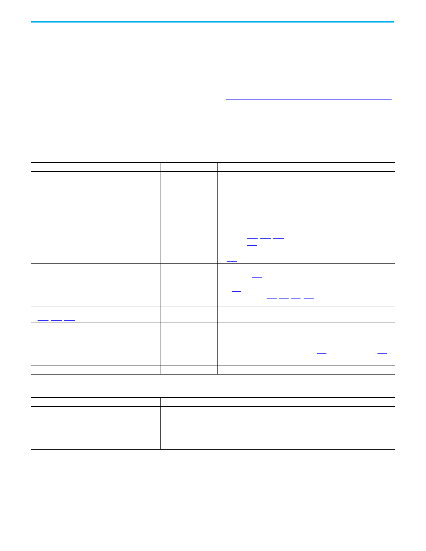
164 Rockwell Automation Publication 520-UM001N-EN-E - July 2024
Chapter 4 Troubleshooting
Common Symptoms and
Corrective Actions
The drive is designed to start from the keypad when shipped. For a basic test of
drive operation:
1. Remove all user I/O wire.
2. Verify safety terminals (S1, S2, and S+) jumper is in place and tightened.
3. Verify that wire jumper is in place between I/O terminals 01 and 11.
4. Verify that the three jumpers are in their proper default positions on the
control board. See PowerFlex 525 Control I/O Terminal Block on page 42
for more information.
5. Reset default parameter values by setting P053
[Reset Defalts] to 2
“Factory Rset”.
6. If safe to do so for your application, press Start on drive keypad. Drive
runs according to the speed potentiometer.
Motor does not Start
Causes Indication Corrective Action
No output voltage to the motor. None
Check the power circuit.
• Check the supply voltage.
• Check all fuses and disconnects.
Check the motor.
• Verify that the motor is connected properly.
Check the control input signals.
• Verify that a Start signal is present. If 2-Wire control is used, verify that either
the Run Forward or Run Reverse signal is active, but not both.
• Verify that I/O Terminal 01 is active.
• Verify that P046
, P048, P050 [Start Source x] matches your configuration.
• Verify that A544
[Reverse Disable] is not prohibiting movement.
• Verify that safety inputs (Safety 1 and Safety 2) are active.
Improper boost setting at initial startup. None Set A530 [Boost Select] to 2 “35.0, VT”.
Drive is Faulted Flashing red status light
Clear fault.
• Press Stop if P045
[Stop Mode] is set to a value between “0” and “3”.
•Cycle drive power.
•Set A551 [Fault Clear] to 1 “Reset Fault” or 2 “Clear Buffer”.
• Cycle digital input if t062
, t063, t065...t068 [DigIn TermBlk xx] is set to
13 “Clear Fault”.
Incorrect programming.
• P046
, P048, P050 [Start Source x] is set incorrectly.
None Check setting for b012
[Control Source].
Incorrect input wiring.
See page 44 for wiring examples.
• 2-wire control requires Run Forward, Run Reverse or Jog
input.
• 3-wire control requires Start and Stop inputs
• Stop input is always required.
None
• Wire inputs correctly and/or install jumper.
• If the PowerFlex 525 Safe Torque Off function is used, verify that inputs are
active.
• If 2-wire or 3-wire mode is used, verify that t062
[DigIn TermBlk 02] and t063
[DigIn TermBlk 03] are set properly.
Incorrect sink/source jumper setting. None Set switch to match wiring scheme.
Drive does not start from Start or Run inputs wired to the terminal block
Causes Indication Corrective Action
Drive is Faulted Flashing red status light
Clear fault.
• Press Stop if P045
[Stop Mode] is set to a value between “0” and “3”.
• Cycle drive power.
• Set A551 [Fault Clear] to 1 “Reset Fault” or 2 “Clear Buffer”.
• Cycle digital input if t062
, t063, t065...t068 [DigIn TermBlk xx] is set to
13 “Clear Fault”.
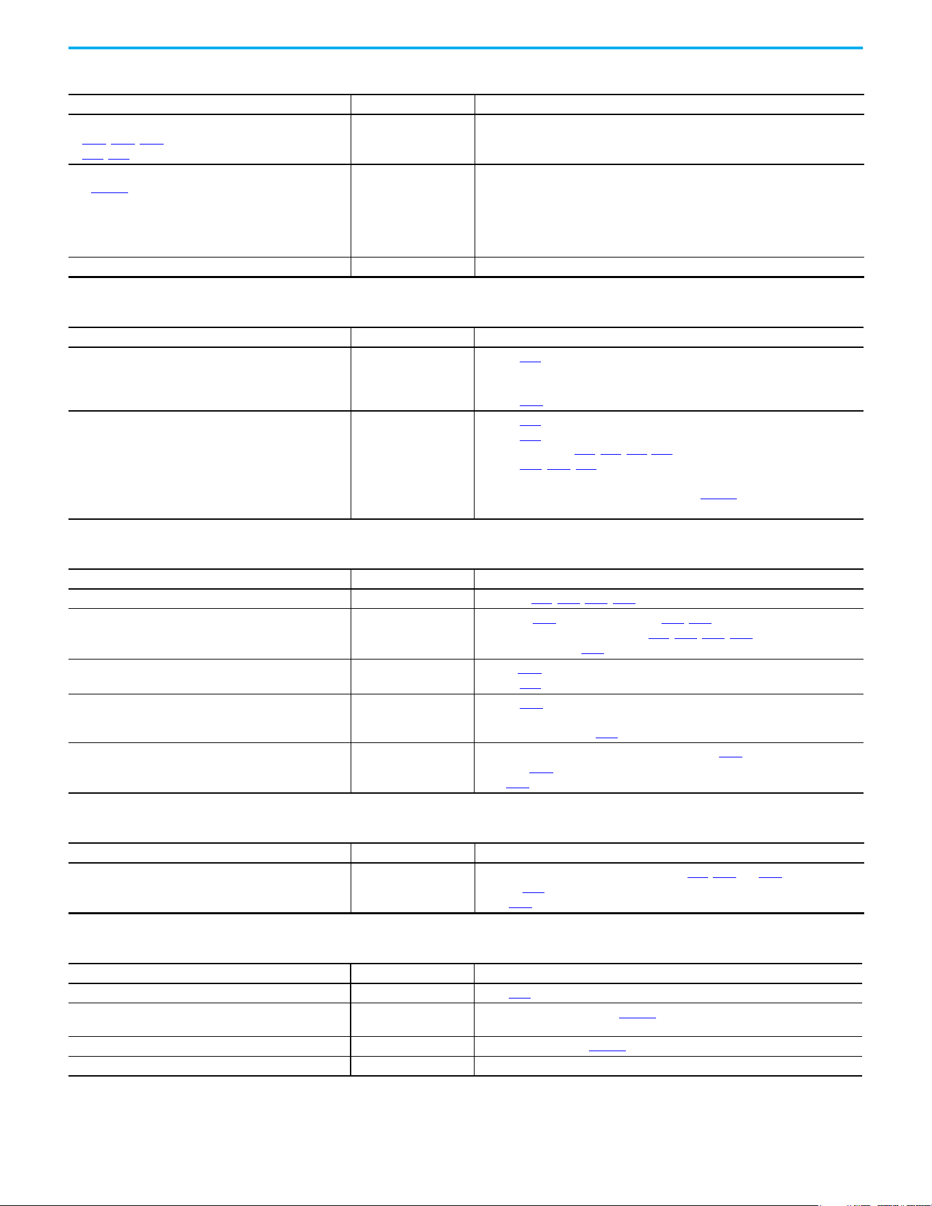
Rockwell Automation Publication 520-UM001N-EN-E - July 2024 165
Chapter 4 Troubleshooting
Incorrect programming.
• P046
, P048, P050 [Start Source x] is set incorrectly.
• t062
, t063 [DigIn TermBlk 02/03] is set incorrectly.
None Check parameter settings.
Incorrect input wiring.
See page 44
for wiring examples.
• 2-wire control requires Run Forward, Run Reverse or Jog
input.
• 3-wire control requires Start and Stop inputs.
• Stop input is always required.
None
• Wire inputs correctly and/or install jumper.
• If the PowerFlex 525 Safe Torque Off function is used, verify that inputs are
active.
Incorrect sink/source jumper setting. None Set switch to match wiring scheme.
Drive does not start from Start or Run inputs wired to the terminal block (Continued)
Causes Indication Corrective Action
Drive does not respond to changes in speed command
Causes Indication Corrective Action
No value is coming from the source of the command.
The drive “Run” indicator
is lit and output is 0 Hz.
•Check b012
[Control Source] for correct source.
• If the source is an analog input, check wiring and use a meter to check for
presence of signal.
•Check b002 [Commanded Freq] to verify correct command.
Incorrect reference source is being selected by remote
device or digital inputs.
None
•Check b012
[Control Source] for correct source.
•Check b014
[Dig In Status] to see if inputs are selecting an alternate source.
Verify settings for t062, t063, t065-t068 [DigIn TermBlk xx].
•Check P047
, P049, P051 [Speed Referencex] for the source of the speed
reference. Reprogram as necessary.
• Review the Speed Reference Control chart on page 49
.
• Verify communications if used.
Motor and/or drive will not accelerate to commanded speed
Causes Indication Corrective Action
Acceleration time is excessive. None Reprogram P041
, A442, A444, A446 [Accel Time x].
Excess load or short acceleration times force the drive into
current limit, slowing or stopping acceleration.
None
• Compare b003
[Output Current] with A484, A485 [Current Limit x].
• Remove excess load or reprogram P041
, A442, A444, A446 [Accel Time x].
• Check for improper A530
[Boost Select] setting.
Speed command source or value is not as expected. None
• Verify b002
[Commanded Freq].
•Check b012
[Control Source] for the proper Speed Command.
Programming is preventing the drive output from
exceeding limiting values.
None
•Check P044
[Maximum Freq] to ensure that speed is not limited by
programming.
• Verify programming of A572
[Speed Ratio].
Torque performance does not match motor characteristics. None
• Set motor nameplate full load amps in parameter P034
[Motor NP FLA].
•Perform P040
[Autotune] “Static Tune” or “Rotate Tune” procedure.
•Set P039
[Torque Perf Mode] to 0 “V/Hz”.
Motor operation is unstable
Causes Indication Corrective Action
Motor data was incorrectly entered. None
• Correctly enter motor nameplate data into P031
, P032 and P033.
•Enable A547
[Compensation].
•Use A530
[Boost Select] to reduce boost level.
Drive will not reverse motor direction
Causes Indication Corrective Action
Reverse is disabled. None Check A544
[Reverse Disable].
Digital input is not selected for reversing control. None
Check [DigIn TermBlk xx] (See page 90
). Choose correct input and program for
reversing mode.
Digital input is incorrectly wired. None Check input wiring (See page 44).
Motor wiring is improperly phased for reverse. None Switch two motor leads.

166 Rockwell Automation Publication 520-UM001N-EN-E - July 2024
Chapter 4 Troubleshooting
Drive does not power up
Causes Indication Corrective Action
No input power to drive. None
• Check the power circuit.
• Check the supply voltage.
• Check all fuses and disconnects.
Control module is not connected properly to power module. None
• Remove power.
• Verify that the control module is properly and fully installed on the power
module.
• Reapply power.
Motor is rotating at zero Hz or slip frequency is not correct
Causes Indication Corrective Action
Incorrect speed calculation. Improper speed.
•Verify P032
[Motor NP Hertz].
• Reduce boost with A530
[Boost Select].
• Set P036
[Motor NP RPM] to motor synchronous speed.
Rockwell Automation Publication 520-UM001N-EN-E - July 2024 167
Appendix A
Supplemental Drive Information
Certifications
Certifications PowerFlex 523 PowerFlex 525
c-UL-us
Listed to UL 508C and CSA C22.2 No. 274
Listed to UL 61800-5-1 and CSA C22.2 No. 274-17
RCM
Australian Communications and Media Authority
In conformity with the following:
Radiocommunications Act: 1992 (including amendments up to 2018)
Radiocommunications Standard: 2017
Radiocommunications Labeling Notice: 2017
Standards applied:
EN 61800-3
In conformity with the following European Directives:
2014/35/EU Low Voltage Directive (LVD)
2014/30/EU EMC Directive (EMC)
2014/34/EU ATEX Directive (ATEX)
2006/42/EC Machinery Directive (MD)
2011/65/EU RoHS Directive (RoHS)
Standards applied:
EN 61800-3
EN 61800-5-1
UKCA
In conformity with the following UK Regulations:
2016 No. 1101 Electrical Equipment (Safety) Regulations (LV)
2016 No. 1091 Electromagnetic Compatibility Regulations (EMC)
2016 No. 1107 Equipment and Protective Systems Intended for Use in Potentially Explosive
Atmospheres Regulations (Ex)
2008 No. 1597 Supply of Machinery (Safety) Regulations (MD)
2012 No. 3032 Restriction of the Use of Certain Hazardous Substances in Electrical and
Electronic Equipment Regulations (RoHS)
2021 No. 745 Ecodesign for Energy-Related Products and Energy Information Regulations
(Eco)
Standards applied:
EN 61800-3
EN 61800-5-1
Functional Safety
(Applicable to PowerFlex 525 drives only)
TÜV Rheinland
Standards applied:
EN ISO 13849-1
EN 61800-5-2
EN 61508 PARTS 1-7
EN 62061
EN 60204-1
Certified to ISO 13849-1 SIL2/PLd with embedded Safe Torque Off function
Meets Functional Safety (FS) when used with embedded Safe Torque Off function
ATEX
TÜV 12 ATEX 7199 X
TÜV 21 UKEX 7031 X
(Applicable to PowerFlex 525 drives only)
Certified to ATEX Directive 2014/34/EU
Group II Category (2) GD Applications with ATEX Approved Motors
Certified to UK Equipment and Protective Systems Intended for Use in Potentially Explosive
Atmospheres Regulations (2016 No. 1107)
Group II Category (2) GD Applications with ATEX Approved Motors
KCC
Korean Registration of Broadcasting and Communications Equipment
Compliant with the following standards:
Article 58-2 of Radio Waves Act, Clause 3
Functional
Safety
Type
Approved
www.tuv.com
ID 0600000000
II (2) G D
168 Rockwell Automation Publication 520-UM001N-EN-E - July 2024
Appendix A Supplemental Drive Information
Environmental
Specifications
EAC
Standards applied:
Low Voltage TP TC 004/2011
EMC TP TC 020/2011
Efficiency Class
Ecodesign regulation (EU) 2019/1781, IE2 efficiency class, see the PowerFlex AC Drive
Performance Specifications per Ecodesign Regulation (EU) 2019/1781 and UK SI 2021 No. 745
Technical Data, publication PFLEX-TD003
for additional information.
AC 156
Tested by Trentec to be compliant with AC156 Acceptance Criteria for Seismic Qualification
Testing of Nonstructural Components and 2003 International Building Code for worst-case
seismic level for USA excluding site class F
SEMI F47
Certified compliant with the following standards:
SEMI F47
IEC 61000-4-11
IEC 61000-4-34
Lloyds Register
(Applicable to PowerFlex 525 drives only)
Lloyd’s Register Type Approval Certificate 12/10068(E1)
RoHS Compliant with the European “Restriction of Hazardous Substances” 2011/65/EU Directive
The drive is also designed to meet the appropriate portions of the following specifications:
NFPA 70 - US National Electrical Code
NEMA ICS 7.1 - Safety standards for Construction and Guide for Selection, Installation, and Operation of
Adjustable Speed Drive Systems.
Certifications PowerFlex 523 PowerFlex 525
Specifications PowerFlex 523 PowerFlex 525
Altitude
Without derating
With derating
See Current Derating Curves on page 17
for derating guidelines.
1000 m (3300 ft) max
Up to 4000 m (13,200 ft) max, with the exception of 600V drives at 2000 m (6600
ft) max.
Max Surrounding Air
Temperature
Without derating
With derating
See Current Derating Curves on page 17 for derating guidelines.
-20…+50 °C (-4…+122 °F)
-20…+60 °C (-4…+140 °F) or -20…+70 °C (-4…+158 °F) with optional Control
Module Fan kit
Storage Temperature
Frame A...D
Frame E
-40…+85 °C (-40…+185 °F)
-40…+70 °C (-40…+158 °F)
Atmosphere
Relative Humidity 0…95% noncondensing
Shock Complies with IEC 60068-2-27
Vibration Complies with IEC 60068-2-6:1995
IMPORTANT
Drive must not be installed in an area where
the ambient atmosphere contains volatile or
corrosive gas, vapors, or dust. If the drive is
not going to be installed for time, it must be
stored in an area where it will not be exposed
to a corrosive atmosphere.
Frame
Size
Operating and Nonoperating Nonoperating (Transportation)
Force
(Shock/Vibration)
Mounting Type
Force
(Shock/Vibration)
Mounting Type
A 15 g / 2 g DIN rail or screw 30 g/ 2.5 g Screw only
B 15 g / 2 g DIN rail or screw 30 g/ 2.5 g Screw only
C 15 g / 2 g DIN rail or screw 30 g/ 2.5 g Screw only
D 15 g / 2 g Screw only 30 g/ 2.5 g Screw only
E 15 g / 1.5 g Screw only 30 g/ 2.5 g Screw only

Rockwell Automation Publication 520-UM001N-EN-E - July 2024 169
Appendix A Supplemental Drive Information
Technical Specifications Protection
Electrical
Conformal Coating
Complies with:
IEC 60721-3-3 to level 3C2 (chemical and gases only)
Surrounding Environment
Pollution Degree
Pollution Degree 1 & 2
See Pollution Degree Ratings According to EN 61800-5-1 on page 52
for descriptions.
All enclosures acceptable.
Sound Pressure Level
(A-weighted), max
Frame A and B
Frame C
Frame D
Frame E
Measurements are taken 1 m (3.3 ft) from the drive.
53 dBA
57 dBA
64 dBA
68 dBA
Specifications PowerFlex 523 PowerFlex 525
Specifications PowerFlex 523 PowerFlex 525
Bus Overvoltage Trip
100…120V AC Input
200…240V AC Input
380…480V AC Input
525…600V AC Input
405V DC bus (equivalent to 150V AC incoming line)
405V DC bus (equivalent to 290V AC incoming line)
810V DC bus (equivalent to 575V AC incoming line)
1005V DC bus (equivalent to 711V AC incoming line)
Bus Undervoltage Trip
100…120V AC Input
200…240V AC Input
380…480V AC Input
190V DC bus (equivalent to 75V AC incoming line)
190V DC bus (equivalent to 150V AC incoming line)
390V DC bus (equivalent to 275V AC incoming line)
Power ride-through 100 ms
Logic Control ride-through 0.5 s minimum, 2 s typical
Electronic Motor Overload
Protection
Provides class 10 motor overload protection according to NEC article 430 and
motor over-temperature protection according to NEC article 430.126 (A) (2).
UL 508C File 29572.
Overcurrent 200% hardware limit, 300% instantaneous fault
Ground Fault Trip Phase-to-ground on drive output
Short Circuit Trip Phase-to-phase on drive output
Specifications PowerFlex 523 PowerFlex 525
Voltage Tolerance -15% / +10%
Frequency Tolerance 47…63 Hz
Input Phases
3-phase input provides full rating. 1-phase input provides 35% rating on 3-phase
drives.
Displacement Power Factor 0.98 across entire speed range
Maximum Short Circuit Rating 100,000 Amps Symmetrical
Actual Short Circuit Rating Determined by AIC Rating of installed fuse/circuit breaker
Transistor Type Insulated gate bipolar transistor (IGBT)
Internal DC Bus Choke
200…240V AC Input
380…480V AC Input
525…600V AC Input
Only for Frame E drive ratings
11 kW (15 HP)
15…18.5 kW (20…25 HP) – Heavy Duty
15…18.5 kW (20…25 HP) – Heavy Duty

170 Rockwell Automation Publication 520-UM001N-EN-E - July 2024
Appendix A Supplemental Drive Information
Control
Specifications PowerFlex 523 PowerFlex 525
Method
Sinusoidal PWM, Volts/Hertz, Sensorless Vector Control, Economizer SVC motor
control, Closed Loop Velocity Vector Control, Surface Mount, and Interior
Permanent Magnet Motor (without encoder), Interior Permanent Magnet Motor
(with encoder)
(Closed Loop Velocity Vector Control, PM motor control, and SynRM are not
applicable to PowerFlex 523 drives)
Carrier Frequency 2…16 kHz, Drive rating based on 4 kHz
Frequency Accuracy
Digital Input
Analog Input
Analog Output
Within ±0.05% of set output frequency
Within 0.5% of maximum output frequency, 10-bit resolution
±2% of full scale, 10-bit resolution
Performance
VHz (Volts per Hertz)
SVC (Sensorless Vector)
SVC Economizer
VVC (Velocity Vector Control)
PM Motor
(1)
(1) For details on specific motor performance, see Knowledgebase article QA34823,“PowerFlex 525 Drive PM Motor Performance
Testing Summary”.
±1% of base speed across a 60:1 speed range
±0.5% of base speed across a 100:1 speed range
±0.5% of base speed across a 100:1 speed range
(Applicable to PowerFlex 525 drives only)
±0.5% of base speed across a 60:1 speed range
±0.5% of base speed, up to a 20:1 speed range
Performance with Encoder
SVC (Sensorless Vector)
SVC Economizer
VVC (Velocity Vector Control)
PM Motor (iPM motor, 10 HP
rating and below)
(1)
(Applicable to PowerFlex 525 drives only)
±0.1% of base speed across a 100:1 speed range
(2)
±0.1% of base speed across a 100:1 speed range
(2)
±0.1% of base speed across a 1000:1 speed range
(2)
±0.1% of base speed, up to a 60:1 speed range
(2) For more information, see Determine Encoder Pulse Per Revolution (PPR) Specification Based on Speed Resolution on
page 221.
Output Voltage Range 0V to rated motor voltage
Output Frequency Range 0...500 Hz (programmable)
Efficiency 97.5% (typical)
Stop Modes
Multiple programmable stop modes including – Ramp, Coast, DC-Brake,
and Ramp to Stop
Accel/Decel
Four independently programmable accel and decel times. Each time may be
programmed from 0…600 s in 0.01 s increments.
Intermittent Overload
Normal Duty
110% Overload capability for up to 60 s, 150% for up to 3 s
Applies for power rating above 15 kW (20 HP) only. Based on 480V drive rating.
Heavy Duty 150% Overload capability for up to 60 s, 180% for up to 3 s
Control Inputs
Specifications PowerFlex 523 PowerFlex 525
Digital
Bandwidth 10 Rad/s for open and closed loop
Quantity
1, dedicated for stop
4, programmable
1, dedicated for stop
6, programmable
Current 6 mA
Type
Source Mode (SRC)
Sink Mode (SNK)
18...24V = ON, 0...6V = OFF
0...6V = ON, 18...24V = OFF
Pulse Train
Quantity
Input Signal
Input Frequency
Current
Consumption
1, shared with one of the programmable digital input terminals.
Transistor contact (open collector)
0…100 kHz
7 mA @ 24V DC maximum
Analog
Quantity (1) Isolated, 0…10V and 4…20mA (2) Isolated, -10…+10V and 4…20mA
Specification
Resolution
0…10V DC Analog
4…20mA Analog
External Pot
10-bit
100 kΩ input impedance
250 Ω input impedance
1…10 kΩ, 2 W minimum
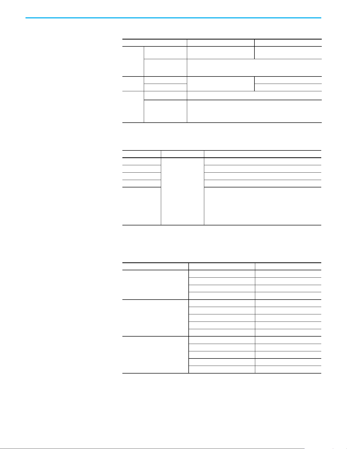
Rockwell Automation Publication 520-UM001N-EN-E - July 2024 171
Appendix A Supplemental Drive Information
Control Outputs
Encoder
Power Specifications
Specifications PowerFlex 523 PowerFlex 525
Relay
Quantity 1, programmable Form C
2, 1 programmable Form A and
1 programmable Form B
Specification
Resistive Rating
Inductive Rating
3.0 A @ 30V DC, 3.0 A @ 125V, 3.0 A @ 240V AC
0.5 A @ 30V DC, 0.5 A @ 125V, 0.5 A @ 240V AC
Opto
Quantity
—
2, programmable
Specification 30V DC, 50 mA Non-inductive
Analog
Quantity
1, nonisolated 0…10V or 4…20 mA
(1)
(1) Feature is not applicable to PowerFlex 523 series A drives.
Specification
Resolution
0…10V DC Analog
4…20 mA Analog
10-bit
1 kΩ minimum
525 Ω maximum
Specifications PowerFlex 523 PowerFlex 525
Type
—
Incremental, dual channel
Supply 12V, 250 mA
Quadrature 90 °C, ±27 °C @ 25 °C (194 °F, ±48.6 °F @ 77 °F)
Duty Cycle 50%, +10%
Requirements
Encoders must be line driver type, quadrature (dual channel), or
pulse (single channel), 3.5…26V DC output, single-ended or
differential and capable of supplying a minimum of 10 mA per
channel.
Allowable input is DC up to a maximum frequency of 250 kHz. The
encoder I/O automatically scales to allow 5V, 12V, and 24V DC
nominal voltages.
Watts Loss
Voltage Output Current (A) Total Watts Loss
100…120V,
50/60 Hz 1-phase
1.6 20.0
2.5 27.0
4.8 53.0
6.0 67.0
200…240V,
50/60 Hz 1-phase
1.6 20.0
2.5 29.0
4.8 50.0
8.0 81.0
11.0 111.0
200…240V,
50/60 Hz 1-phase
w/ EMC Filter
1.6 20.0
2.5 29.0
4.8 53.0
8.0 84.0
11.0 116.0

172 Rockwell Automation Publication 520-UM001N-EN-E - July 2024
Appendix A Supplemental Drive Information
200…240V,
50/60 Hz 3-phase
1.6 20.0
2.5 29.0
5.0 50.0
8.0 79.0
11.0 107.0
17.5 148.0
24.0 259.0
32.2 323.0
48.3 584.0
62.1 708.0
380…480V,
50/60 Hz 3-phase
1.4 27.0
2.3 37.0
4.0 62.0
6.0 86.0
10.5 129.0
13.0 170.0
17.0 221.0
24.0 303.0
30.0 387.0
380…480V,
50/60 Hz 3-phase
w/ EMC Filter
1.4 27.0
2.3 37.0
4.0 63.0
6.0 88.0
10.5 133.0
13.0 175.0
17.0 230.0
24.0 313.0
30.0 402.0
37.0 602.0
43.0 697.0
525…600V,
50/60 Hz 3-phase
0.9 22.0
1.7 32.0
3.0 50.0
4.2 65.0
6.6 95.0
9.9 138.0
12.0 164.0
19.0 290.0
22.0 336.0
27.0 466.0
32.0 562.0
Watts Loss (Continued)
Voltage Output Current (A) Total Watts Loss

Rockwell Automation Publication 520-UM001N-EN-E - July 2024 173
Appendix A Supplemental Drive Information
Input Current Scaling (Optional)
You can use a higher drive rating by scaling the input current based on the
output current that is required for your application. You can use a lower input
current rating based on the motor FLA rating. See the PowerFlex 520-series
Input Current Rating Scaled by the Motor FLA on page 173 table for more
information.
Use the motor FLA rating in columns 1…4 and check the corresponding input
rating in columns A…D. For example when using a 25A-V1P6N104 drive, if the
motor has an FLA rating of 1.6, the input rating is 6.4 amps.
PowerFlex 520-series Input Current Rating Scaled by the Motor FLA
PowerFlex 523 PowerFlex 525 Output Current: Motor FLA Input Drive Current Rating
Catalog Number Catalog Number 1 2 3 4 A B C D
100…120V AC (-15%, +10%) – 1-phase Input, 0…230V 3-phase Output
25A-V1P6N104 — 1.6 1.3 1.0 0.8 6.4 5.2 4.0 3.2
25A-V2P5N104 25B-V2P5N104 2.5 2.0 1.6 1.3 9.6 7.7 6.2 4.8
25A-V4P8N104 25B-V4P8N104 4.8 3.8 3.1 2.4 19.2 15.4 12.5 9.6
25A-V6P0N104 25B-V6P0N104 6.0 4.8 3.9 3.0 24.0 19.2 15.6 12.0
200…240V AC (-15%, +10%) – 1-phase Input, 0…230V 3-phase Output
25A-A1P6N104 — 1.6 1.3 1.0 0.8 5.3 4.3 3.4 2.7
25A-A2P5N104 25B-A2P5N104 2.5 2.0 1.6 1.3 6.5 5.2 4.2 3.3
25A-A4P8N104 25B-A4P8N104 4.8 3.8 3.1 2.4 10.7 8.6 7.0 5.4
25A-A8P0N104 25B-A8P0N104 8.0 6.4 5.2 4.0 18.0 14.4 11.7 9.0
25A-A011N104 25B-A011N104 11.0 8.8 7.2 5.5 22.9 18.3 14.9 11.5
200…240V AC (-15%, +10%) – 1-phase Input with EMC Filter, 0…230V 3-phase Output
25A-A1P6N114 — 1.6 1.3 1.0 0.8 5.3 4.3 3.4 2.7
25A-A2P5N114 25B-A2P5N114 2.5 2.0 1.6 1.3 6.5 5.2 4.2 3.3
25A-A4P8N114 25B-A4P8N114 4.8 3.8 3.1 2.4 10.7 8.6 7.0 5.4
25A-A8P0N114 25B-A8P0N114 8.0 6.4 5.2 4.0 18.0 14.4 11.7 9.0
25A-A011N114 25B-A011N114 11.0 8.8 7.2 5.5 22.9 18.3 14.9 11.5
200…240V AC (-15%, +10%) – 3-phase Input, 0…230V 3-phase Output
25A-B1P6N104 — 1.6 1.3 1.0 0.8 1.9 1.5 1.2 1.0
25A-B2P5N104 25B-B2P5N104 2.5 2.0 1.6 1.3 2.7 2.2 1.8 1.4
25A-B5P0N104 25B-B5P0N104 5.0 4.0 3.2 2.5 5.8 4.6 3.8 2.9
25A-B8P0N104 25B-B8P0N104 8.0 6.4 5.2 4.0 9.5 7.6 6.2 4.8
25A-B011N104 25B-B011N104 11.0 8.8 7.2 5.5 13.8 11.0 9.0 6.9
25A-B017N104 25B-B017N104 17.5 14.0 11.4 8.8 21.1 16.9 13.7 10.6
25A-B024N104 25B-B024N104 24.0 19.2 15.6 12.0 26.6 21.3 17.3 13.3
25A-B032N104 25B-B032N104 32.2 25.8 20.9 16.1 34.8 27.8 22.6 17.4
25A-B048N104 25B-B048N104 48.3 38.6 31.4 24.2 44.0 35.2 28.6 22.0
25A-B062N104 25B-B062N104 62.1 49.7 40.4 31.1 56.0 44.8 36.4 28.0
380…480V AC (-15%, +10%) – 3-phase Input, 0…460V 3-phase Output
25A-D1P4N104 25B-D1P4N104 1.4 1.1 0.9 0.7 1.9 1.5 1.2 1.0
25A-D2P3N104 25B-D2P3N104 2.3 1.8 1.5 1.2 3.2 2.6 2.1 1.6
25A-D4P0N104 25B-D4P0N104 4.0 3.2 2.6 2.0 5.7 4.6 3.7 2.9
25A-D6P0N104 25B-D6P0N104 6.0 4.8 3.9 3.0 7.5 6.0 4.9 3.8
25A-D010N104 25B-D010N104 10.5 8.4 6.8 5.3 13.8 11.0 9.0 6.9
25A-D013N104 25B-D013N104 13.0 10.4 8.5 6.5 15.4 12.3 10.0 7.7
25A-D017N104 25B-D017N104 17.0 13.6 11.1 8.5 18.4 14.7 12.0 9.2
25A-D024N104 25B-D024N104 24.0 19.2 15.6 12.0 26.4 21.1 17.2 13.2
25A-D030N104 25B-D030N104 30.0 24.0 19.5 15.0 33.0 26.4 21.5 16.5

174 Rockwell Automation Publication 520-UM001N-EN-E - July 2024
Appendix A Supplemental Drive Information
380…480V AC (-15%, +10%) – 3-phase Input with EMC Filter, 0…460V 3-phase Output
25A-D1P4N114 25B-D1P4N114 1.4 1.1 0.9 0.7 1.9 1.5 1.2 1.0
25A-D2P3N114 25B-D2P3N114 2.3 1.8 1.5 1.2 3.2 2.6 2.1 1.6
25A-D4P0N114 25B-D4P0N114 4.0 3.2 2.6 2.0 5.7 4.6 3.7 2.9
25A-D6P0N114 25B-D6P0N114 6.0 4.8 3.9 3.0 7.5 6.0 4.9 3.8
25A-D010N114 25B-D010N114 10.5 8.4 6.8 5.3 13.8 11.0 9.0 6.9
25A-D013N114 25B-D013N114 13.0 10.4 8.5 6.5 15.4 12.3 10.0 7.7
25A-D017N114 25B-D017N114 17.0 13.6 11.1 8.5 18.4 14.7 12.0 9.2
25A-D024N114 25B-D024N114 24.0 19.2 15.6 12.0 26.4 21.1 17.2 3.2
25A-D030N114 25B-D030N114 30.0 24.0 19.5 15.0 33.0 26.4 21.5 16.5
25A-D037N114 25B-D037N114 37.0 29.6 24.1 18.5 33.7 27.0 21.9 16.9
25A-D043N114 25B-D043N114 43.0 34.4 28.0 21.5 38.9 31.1 25.3 19.5
525…600V AC (-15%, +10%) – 3-phase Input, 0…575V 3-phase Output
25A-E0P9N104 25B-E0P9N104 0.9 0.7 0.6 0.5 1.2 1.0 0.8 0.6
25A-E1P7N104 25B-E1P7N104 1.7 1.4 1.1 0.9 2.3 1.8 1.5 1.2
25A-E3P0N104 25B-E3P0N104 3.0 2.4 2.0 1.5 3.8 3.0 2.5 1.9
25A-E4P2N104 25B-E4P2N104 4.2 3.4 2.7 2.1 5.3 4.2 3.4 2.7
25A-E6P6N104 25B-E6P6N104 6.6 5.3 4.3 3.3 8.0 6.4 5.2 4.0
25A-E9P9N104 25B-E9P9N104 9.9 7.9 6.4 5.0 11.2 9.0 7.3 5.6
25A-E012N104 25B-E012N104 12.0 9.6 7.8 6.0 13.5 10.8 8.8 6.8
25A-E019N104 25B-E019N104 19.0 15.2 12.4 9.5 24.0 19.2 15.6 12.0
25A-E022N104 25B-E022N104 22.0 17.6 14.3 11.0 27.3 21.8 17.7 13.7
25A-E027N104 25B-E027N104 27.0 21.6 17.6 13.5 24.7 19.8 16.1 12.4
25A-E032N104 25B-E032N104 32.0 25.6 20.8 16.0 29.2 23.4 19.0 14.6
PowerFlex 520-series Input Current Rating Scaled by the Motor FLA (Continued)
PowerFlex 523 PowerFlex 525 Output Current: Motor FLA Input Drive Current Rating
Catalog Number Catalog Number 1 2 3 4 A B C D

Rockwell Automation Publication 520-UM001N-EN-E - July 2024 175
Appendix B
Accessories and Dimensions
Product Selection
Catalog Number Description
25B - V 2P5 N 1 0 4
Drive Voltage Rating Rating Enclosure HIM Emission Class Version
PowerFlex 520-series Drive Ratings
Output Ratings
Input
Voltage Range
Frame
Size
PowerFlex 523 PowerFlex 525
Normal Duty Heavy Duty
Output
Current (A)
HP kW HP kW Catalog No. Catalog No.
100…120V AC (-15%, +10%) – 1-phase Input, 0…230V 3-phase Output
0.25 0.2 0.25 0.2 1.6 85…132 A
25A-V1P6N104
(1)
—
0.5 0.4 0.5 0.4 2.5 85…132 A 25A-V2P5N104 25B-V2P5N104
1.0 0.75 1.0 0.75 4.8 85…132 B 25A-V4P8N104 25B-V4P8N104
1.5 1.1 1.5 1.1 6.0 85…132 B 25A-V6P0N104 25B-V6P0N104
200…240V AC (-15%, +10%) – 1-phase Input, 0…230V 3-phase Output
0.25 0.2 0.25 0.2 1.6 170…264 A
25A-A1P6N104
(1)
—
0.5 0.4 0.5 0.4 2.5 170…264 A 25A-A2P5N104 25B-A2P5N104
1.0 0.75 1.0 0.75 4.8 170…264 A 25A-A4P8N104 25B-A4P8N104
2.0 1.5 2.0 1.5 8.0 170…264 B 25A-A8P0N104 25B-A8P0N104
3.0 2.2 3.0 2.2 11.0 170…264 B 25A-A011N104 25B-A011N104
200…240V AC (-15%, +10%) – 1-phase Input with EMC Filter, 0…230V 3-phase Output
0.25 0.2 0.25 0.2 1.6 170…264 A 25A-A1P6N114 —
0.5 0.4 0.5 0.4 2.5 170…264 A 25A-A2P5N114 25B-A2P5N114
1.0 0.75 1.0 0.75 4.8 170…264 A 25A-A4P8N114 25B-A4P8N114
2.0 1.5 2.0 1.5 8.0 170…264 B 25A-A8P0N114 25B-A8P0N114
3.0 2.2 3.0 2.2 11.0 170…264 B 25A-A011N114 25B-A011N114
200…240V AC (-15%, +10%) – 3-phase Input, 0…230V 3-phase Output
0.25 0.2 0.25 0.2 1.6 170…264 A
25A-B1P6N104
(1)
—
0.5 0.4 0.5 0.4 2.5 170…264 A 25A-B2P5N104 25B-B2P5N104
1.0 0.75 1.0 0.75 5.0 170…264 A 25A-B5P0N104 25B-B5P0N104
2.0 1.5 2.0 1.5 8.0 170…264 A 25A-B8P0N104 25B-B8P0N104
3.0 2.2 3.0 2.2 11.0 170…264 A 25A-B011N104 25B-B011N104
5.0 4.0 5.0 4.0 17.5 170…264 B 25A-B017N104 25B-B017N104
7.5 5.5 7.5 5.5 24.0 170…264 C 25A-B024N104 25B-B024N104
10.0 7.5 10.0 7.5 32.2 170…264 D 25A-B032N104 25B-B032N104
15.0 11.0 10.0 7.5 48.3 170…264 E 25A-B048N104 25B-B048N104
20.0 15.0 15.0 11.0 62.1 170…264 E 25A-B062N104 25B-B062N104
380…480V AC (-15%, +10%) – 3-phase Input, 0…460V 3-phase Output
(2)
0.5 0.4 0.5 0.4 1.4 323…528 A
25A-D1P4N104
(1)
25B-D1P4N104
(1)
1.0 0.75 1.0 0.75 2.3 323…528 A 25A-D2P3N104 25B-D2P3N104
2.0 1.5 2.0 1.5 4.0 323…528 A 25A-D4P0N104 25B-D4P0N104
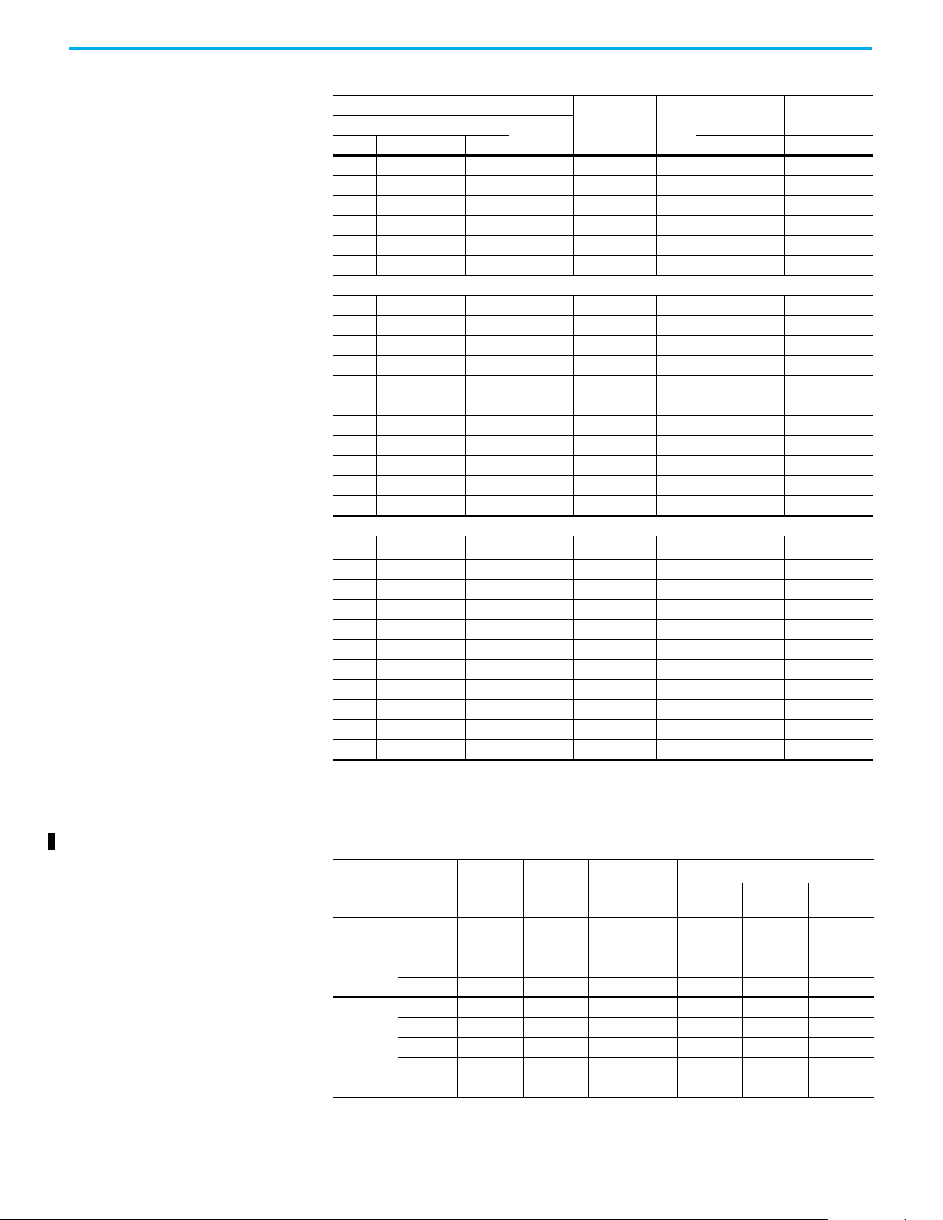
176 Rockwell Automation Publication 520-UM001N-EN-E - July 2024
Appendix B Accessories and Dimensions
3.0 2.2 3.0 2.2 6.0 323…528 A 25A-D6P0N104 25B-D6P0N104
5.0 4.0 5.0 4.0 10.5 323…528 B 25A-D010N104 25B-D010N104
7.5 5.5 7.5 5.5 13.0 323…528 C 25A-D013N104 25B-D013N104
10.0 7.5 10.0 7.5 17.0 323…528 C 25A-D017N104 25B-D017N104
15.0 11.0 15.0 11.0 24.0 323…528 D 25A-D024N104 25B-D024N104
20.0 15.0 15.0 11.0 30.0 323…528 D 25A-D030N104 25B-D030N104
380…480V AC (-15%, +10%) – 3-phase Input with EMC Filter, 0…460V 3-phase Output
0.5 0.4 0.5 0.4 1.4 323…528 A 25A-D1P4N114 25B-D1P4N114
1.0 0.75 1.0 0.75 2.3 323…528 A 25A-D2P3N114 25B-D2P3N114
2.0 1.5 2.0 1.5 4.0 323…528 A 25A-D4P0N114 25B-D4P0N114
3.0 2.2 3.0 2.2 6.0 323…528 A 25A-D6P0N114 25B-D6P0N114
5.0 4.0 5.0 4.0 10.5 323…528 B 25A-D010N114 25B-D010N114
7.5 5.5 7.5 5.5 13.0 323…528 C 25A-D013N114 25B-D013N114
10.0 7.5 10.0 7.5 17.0 323…528 C 25A-D017N114 25B-D017N114
15.0 11.0 15.0 11.0 24.0 323…528 D 25A-D024N114 25B-D024N114
20.0 15.0 15.0 11.0 30.0 323…528 D 25A-D030N114 25B-D030N114
25.0 18.5 20.0 15.0 37.0 323…528 E 25A-D037N114 25B-D037N114
30.0 22.0 25.0 18.5 43.0 323…528 E 25A-D043N114 25B-D043N114
525…600V AC (-15%, +10%) – 3-phase Input, 0…575V 3-phase Output
0.5 0.4 0.5 0.4 0.9 446…660 A
25A-E0P9N104
(1)
25B-E0P9N104
(1)
1.0 0.75 1.0 0.75 1.7 446…660 A 25A-E1P7N104 25B-E1P7N104
2.0 1.5 2.0 1.5 3.0 446…660 A 25A-E3P0N104 25B-E3P0N104
3.0 2.2 3.0 2.2 4.2 446…660 A 25A-E4P2N104 25B-E4P2N104
5.0 4.0 5.0 4.0 6.6 446…660 B 25A-E6P6N104 25B-E6P6N104
7.5 5.5 7.5 5.5 9.9 446…660 C 25A-E9P9N104 25B-E9P9N104
10.0 7.5 10.0 7.5 12.0 446…660 C 25A-E012N104 25B-E012N104
15.0 11.0 15.0 11.0 19.0 446…660 D 25A-E019N104 25B-E019N104
20.0 15.0 15.0 11.0 22.0 446…660 D 25A-E022N104 25B-E022N104
25.0 18.5 20.0 15.0 27.0 446…660 E 25A-E027N104 25B-E027N104
30.0 22.0 25.0 18.5 32.0 446…660 E 25A-E032N104 25B-E032N104
(1) These drive ratings do not come with a heatsink cooling fan and are in accordance with design specifications.
(2) A non-filtered drive is not available for 380…480V AC 25 HP (18.5 kW) and 30 HP (22.0 kW) ratings. Filtered drives are
available, however you must verify that the application supports a filtered drive.
Dynamic Brake Resistors
Drive Ratings
Minimum
Resistance,
Ω ±10%
Resistance,
Ω ±5%
Catalog No.
(1)(2)
Fuse Protection
(3)
Input
Voltage
HP kW
BR-
(4)
DC+/BR+ DC-
100…120V
50/60 Hz
1-phase
0.25 0.2 56 91 AK-R2-091P500 PV-15A10F 1000GH-016 1000GH-016
0.5 0.4 56 91 AK-R2-091P500 PV-15A10F 1000GH-016 1000GH-016
1.0 0.75 56 91 AK-R2-091P500 PV-15A10F 1000GH-016 1000GH-016
1.5 1.1 41 91 AK-R2-091P500 PV-15A10F 1000GH-020 1000GH-020
200…240V
50/60 Hz
1-phase
0.25 0.2 56 91 AK-R2-091P500 PV-15A10F 1000GH-016 1000GH-016
0.5 0.4 56 91 AK-R2-091P500 PV-15A10F 1000GH-016 1000GH-016
1.0 0.75 56 91 AK-R2-091P500 PV-15A10F 1000GH-016 1000GH-016
2.0 1.5 41 91 AK-R2-091P500 PV-32ANH1 1000GH-025 1000GH-025
3.0 2.2 32 47 AK-R2-047P500 PV-32ANH1 1000GH-032 1000GH-032
PowerFlex 520-series Drive Ratings (Continued)
Output Ratings
Input
Voltage Range
Frame
Size
PowerFlex 523 PowerFlex 525
Normal Duty Heavy Duty
Output
Current (A)
HP kW HP kW Catalog No. Catalog No.
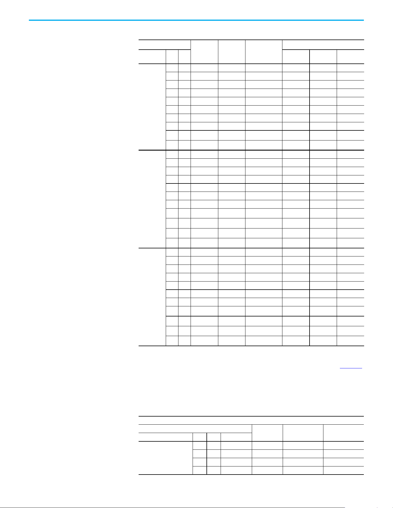
Rockwell Automation Publication 520-UM001N-EN-E - July 2024 177
Appendix B Accessories and Dimensions
200…240V
50/60 Hz
3-phase
0.25 0.2 56 91 AK-R2-091P500 PV-20A10F 1000GH-016 1000GH-016
0.5 0.4 56 91 AK-R2-091P500 PV-20A10F 1000GH-016 1000GH-016
1.0 0.75 56 91 AK-R2-091P500 PV-20A10F 1000GH-016 1000GH-016
2.0 1.5 41 91 AK-R2-091P500 PV-20A10F 1000GH-025 1000GH-025
3.0 2.2 32 47 AK-R2-047P500 PV-20A10F 1000GH-032 1000GH-032
5.0 4.0 18 47 AK-R2-047P500 PV-32ANH1 1000GH-050 1000GH-050
7.5 5.5 16 30 AK-R2-030P1K2 PV-40ANH1 1000GH-063 1000GH-063
10.0 7.5 14 30 AK-R2-030P1K2 1000GH-040 1000GH-080 1000GH-080
15.0 11.0 14 15
AK-R2-030P1K2
(5)
1000GH-050 1000GH-100 1000GH-100
20.0 15.0 10 15
AK-R2-030P1K2
(5)
1000GH-050 1000GH-125 1000GH-125
380…480V
50/60 Hz
3-phase
0.5 0.4 89 360 AK-R2-360P500 PV-10A10F 1000GH-016 1000GH-016
1.0 0.75 89 360 AK-R2-360P500 PV-10A10F 1000GH-016 1000GH-016
2.0 1.5 89 360 AK-R2-360P500 PV-10A10F 1000GH-016 1000GH-016
3.0 2.2 89 120 AK-R2-120P1K2 PV-10A10F 1000GH-016 1000GH-016
5.0 4.0 47 120 AK-R2-120P1K2 PV-20A10F 1000GH-032 1000GH-032
7.5 5.5 47 120 AK-R2-120P1K2 PV-32ANH1 1000GH-032 1000GH-032
10.0 7.5 47 120 AK-R2-120P1K2 PV-32ANH1 1000GH-040 1000GH-040
15.0 11.0 43 60
AK-R2-120P1K2
(5)
1000GH-025 1000GH-063 1000GH-063
20.0 15.0 43 60
AK-R2-120P1K2
(5)
1000GH-025 1000GH-080 1000GH-080
25.0 18.5 27 40
AK-R2-120P1K2
(6)
1000GH-040 1000GH-080 1000GH-080
30.0 22.0 27 40
AK-R2-120P1K2
(6)
1000GH-040 1000GH-080 1000GH-080
525…600V
50/60 Hz
3-phase
0.5 0.4 112 360 AK-R2-360P500 PV-10A10F 1000GH-016 1000GH-016
1.0 0.75 112 360 AK-R2-360P500 PV-10A10F 1000GH-016 1000GH-016
2.0 1.5 112 360 AK-R2-360P500 PV-10A10F 1000GH-016 1000GH-016
3.0 2.2 112 120 AK-R2-120P1K2 PV-10A10F 1000GH-016 1000GH-016
5.0 4.0 86 120 AK-R2-120P1K2 PV-12A10F 1000GH-025 1000GH-025
7.5 5.5 59 120 AK-R2-120P1K2 PV-20A10F 1000GH-025 1000GH-025
10.0 7.5 59 120 AK-R2-120P1K2 PV-20A10F 1000GH-032 1000GH-032
15.0 11.0 59 60
AK-R2-120P1K2
(5)
1000GH-025 1000GH-050 1000GH-050
20.0 15.0 59 60
AK-R2-120P1K2
(5)
1000GH-025 1000GH-063 1000GH-063
25.0 18.5 53 60
AK-R2-120P1K2
(5)
1000GH-040 1000GH-063 1000GH-063
30.0 22.0 34 40
AK-R2-120P1K2
(6)
1000GH-040 1000GH-063 1000GH-063
(1) The resistors that are listed in these tables are rated for 5% duty cycle.
(2) Use of Rockwell Automation resistors is always recommended. The resistors that are listed have been carefully selected for
optimizing performance in a variety of applications. Alternative resistors may be used, however, care must be taken when
making a selection. See the PowerFlex Dynamic Braking Resistor Calculator Application Technique, publication PFLEX-AT001
.
(3) For IEC applications, DC Fuse is mandatory when these terminals are connected. Connect the fuse to the terminal. Use the
specified part number. PV-xxxxxx fuse is from Bussman. 1000GH-xxx fuse is from Hinode.
(4) For UL applications, a DC fuse is mandatory at the BR- terminal when used with a dynamic brake resistor.
(5) Requires two resistors that are wired in parallel.
(6) Requires three resistors that are wired in parallel.
EMC Line Filters
Short-circuit Current Rating (SCCR) = 100 kA
Drive Ratings
Frame Size
For 100 m
Catalog No.
For 150 m
(1)
Catalog No.
Input Voltage HP kW Current (A)
100…120V
50/60 Hz
1-phase
0.25 0.2 1.6 A
25-RF011-AL
—
0.5 0.4 2.5 A
25-RF011-AL
—
1.0 0.75 4.8 B
25-RF023-BL
—
1.5 1.1 6.0 B
25-RF023-BL
—
Dynamic Brake Resistors (Continued)
Drive Ratings
Minimum
Resistance,
Ω ±10%
Resistance,
Ω ±5%
Catalog No.
(1)(2)
Fuse Protection
(3)
Input
Voltage
HP kW
BR-
(4)
DC+/BR+ DC-
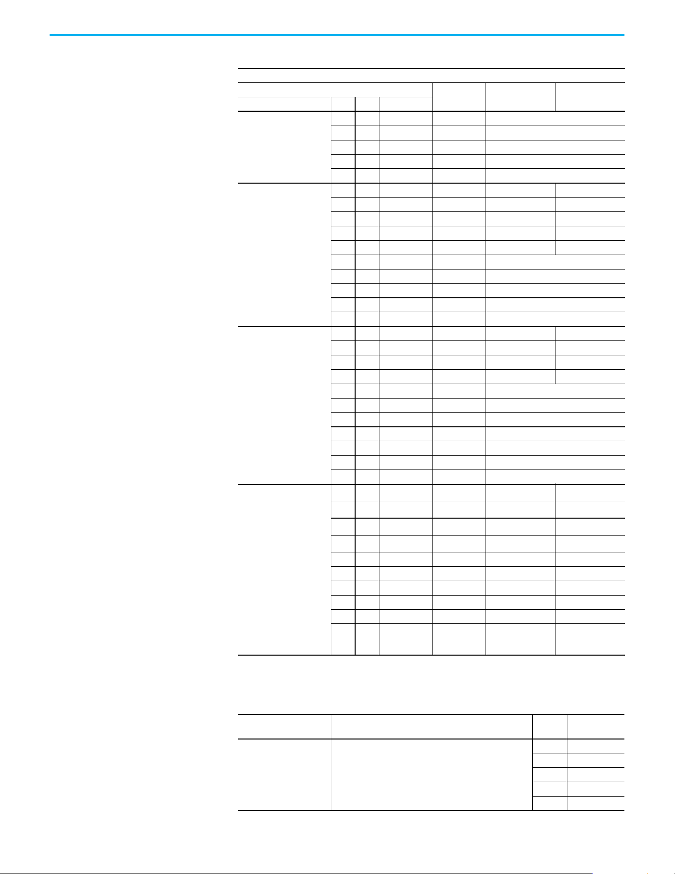
178 Rockwell Automation Publication 520-UM001N-EN-E - July 2024
Appendix B Accessories and Dimensions
200…240V
50/60 Hz
1-phase
0.25 0.2 1.6 A 25-RF011-AL
0.5 0.4 2.5 A 25-RF011-AL
1.0 0.75 4.8 A 25-RF011-AL
2.0 1.5 8.0 B 25-RF023-BL
3.0 2.2 11.0 B 25-RF023-BL
200…240V
50/60 Hz
3-phase
0.25 0.2 1.6 A 25-RF014-AL 25-RF021-BL
0.5 0.4 2.5 A 25-RF014-AL 25-RF021-BL
1.0 0.75 5.0 A 25-RF014-AL 25-RF021-BL
2.0 1.5 8.0 A 25-RF014-AL 25-RF021-BL
3.0 2.2 11.0 A 25-RF014-AL 25-RF021-BL
5.0 4.0 17.5 B 25-RF021-BL
7.5 5.5 24.0 C 25-RF027-CL
10.0 7.5 32.2 D 25-RF035-DL
15.0 11.0 48.3 E 25-RF056-EL
20.0 15.0 62.1 E 25-RF056-EL
380…480V
50/60 Hz
3-phase
0.5 0.4 1.4 A 25-RF7P5-AL 25-RF014-BL
1.0 0.75 2.3 A 25-RF7P5-AL 25-RF014-BL
2.0 1.5 4.0 A 25-RF7P5-AL 25-RF014-BL
3.0 2.2 6.0 A 25-RF7P5-AL 25-RF014-BL
5.0 4.0 10.5 B 25-RF014-BL
7.5 5.5 13.0 C 25-RF018-CL
10.0 7.5 17.0 C 25-RF018-CL
15.0 11.0 24.0 D 25-RF033-DL
20.0 15.0 30.0 D 25-RF033-DL
25.0 18.5 37.0 E 25-RF039-EL
30.0 22.0 43.0 E 25-RF039-EL
525…600V
50/60 Hz
3-phase
0.5 0.4 0.9 A
25-RF8P0-BL
(2)
—
1.0 0.75 1.7 A
25-RF8P0-BL
(2)
—
2.0 1.5 3.0 A
25-RF8P0-BL
(2)
—
3.0 2.2 4.2 A
25-RF8P0-BL
(2)
—
5.0 4.0 6.6 B 25-RF8P0-BL —
7.5 5.5 9.9 C 25-RF014-CL —
10.0 7.5 12.0 C 25-RF014-CL —
15.0 11.0 19.0 D 25-RF027-DL —
20.0 15.0 22.0 D 25-RF027-DL —
25.0 18.5 27.0 E 25-RF029-EL —
30.0 22.0 32.0 E
25-RF029-EL
(2)
—
(1) Requires Series B filters to achieve 150 m rating.
(2) The 600V drive rating must be matched with a frame B Line Filter.
EMC Plates
Item Description
Frame
Size
Catalog No.
EMC Plate Optional grounding plate for shielded cables.
A 25-EMC1-FA
B 25-EMC1-FB
C 25-EMC1-FC
D 25-EMC1-FD
E 25-EMC1-FE
EMC Line Filters (Continued)
Short-circuit Current Rating (SCCR) = 100 kA
Drive Ratings
Frame Size
For 100 m
Catalog No.
For 150 m
(1)
Catalog No.
Input Voltage HP kW Current (A)
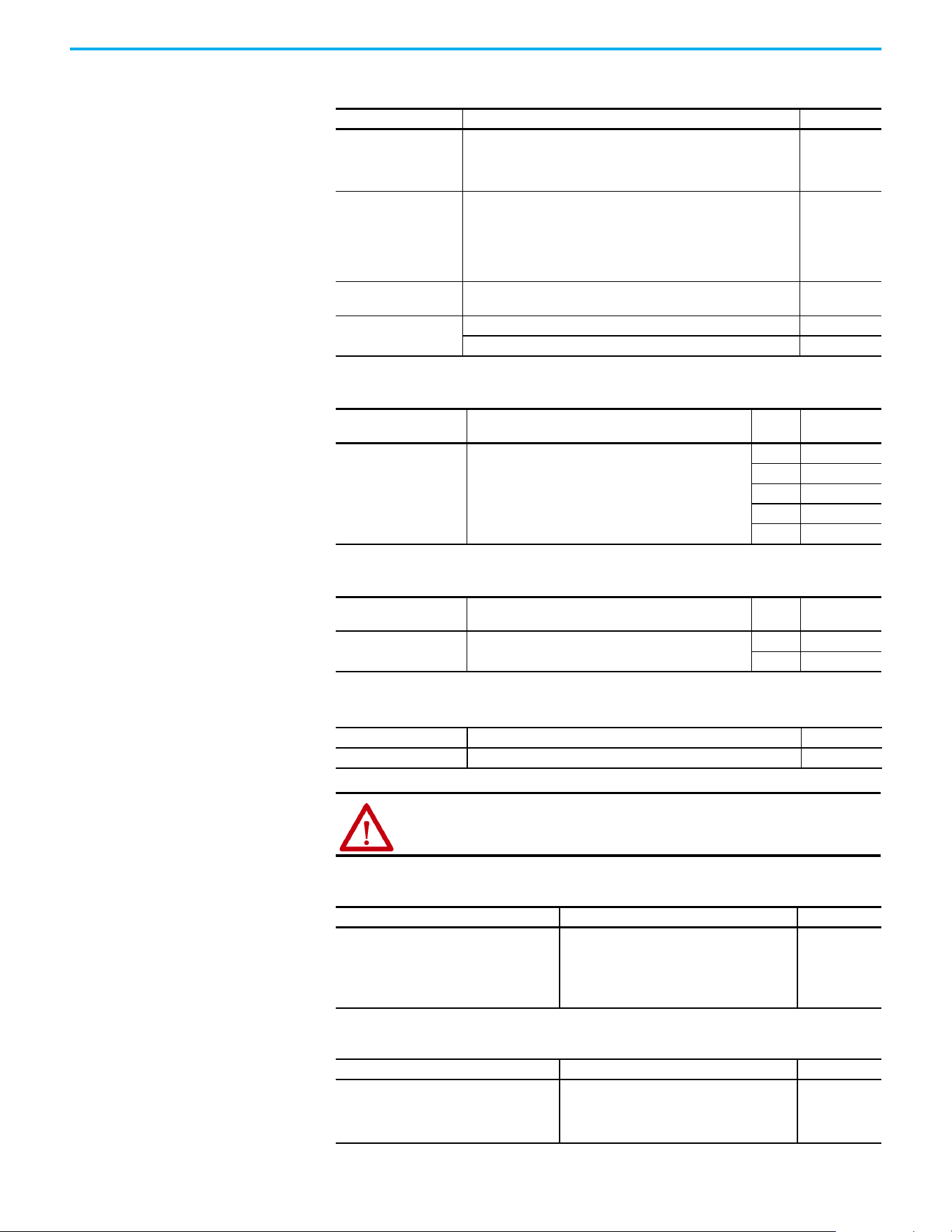
Rockwell Automation Publication 520-UM001N-EN-E - July 2024 179
Appendix B Accessories and Dimensions
Human Interface Module (HIM) Option Kits and Accessories
Item Description Catalog No.
LCD Display, Remote
Panel Mount
Digital speed control
Copycat capable
IP66 (NEMA Type 4X/12) indoor use only
Includes 2.0 meter cable
22-HIM-C2S
LCD Display, Remote
Handheld
Digital speed control
Full numeric keyboard
Copycat capable
IP 30 (NEMA Type 1)
Includes 1.0 meter cable
Panel mount with optional Bezel Kit
22-HIM-A3
Bezel Kit
Panel mount for LCD Display, Remote Handheld unit, IP 30 (NEMA
Type 1) Includes 2.0 m (6.6 ft) DSI cable
22-HIM-B1
DSI HIM Cable
(DSI HIM to RJ45 cable)
1.0 m (3.3 ft) 22-HIM-H10
2.9 m (9.51 ft) 22-HIM-H30
IP 30/NEMA 1/UL Type 1 Kit
Item Description
Frame
Size
Catalog No.
IP 30/NEMA 1/UL Type 1 Kit
Field installed kit. Converts the drive to an IP 30/NEMA 1/UL
Type 1 enclosure. Includes conduit box with mounting
screws and plastic top panel.
A25-JBAA
B25-JBAB
C25-JBAC
D25-JBAD
E25-JBAE
Control Module Fan Kit
Item Description
Frame
Size
Catalog No.
Control Module Fan Kit
For use with drive in environments with ambient
temperatures up to 70 °C or horizontal mounting.
A...D 25-FAN1-70C
E 25-FAN2-70C
Incremental Encoder Input Option
Item Description Catalog No.
Incremental Encoder Incremental encoder input option board. 25-ENC-1
WARNING: Only the 25-ENC-1 Encoder works properly in the PowerFlex 525
drive. Installing an incorrect encoder card, such as the PowerFlex 527
25-ENC-2 causes damage to the PowerFlex 525 drive.
PowerFlex 520-series Drives Jumper Spare Kit
Item Description Catalog No.
• Wire Jumper
• MOV Jumper
• Protective Jumper (Control I/O terminal
block)
• Analog/Signal Configuration Jumper
Replace the Protective Jumper from your Power
module, drive Terminals Safety 1, Safety 2, and
Safety +24V (S1, S2, S+) of the Control Module.
25-ACCS-Drive
PowerFlex 520 Series Communication Adapter Spare Kit
Item Description Catalog No.
• PowerFlex 525 Encoder card removable
terminal block
• PowerFlex 523/525 Communication Adapter
interface connector
Communication adapter spare kits 25-ACCS-COMM

180 Rockwell Automation Publication 520-UM001N-EN-E - July 2024
Appendix B Accessories and Dimensions
Bulletin 160 to PowerFlex 520-series Mounting Adapter Plate
Item Description
B160
Frame
Size
Catalog No.
Mounting Adapter Plate
For use with drive when replacing Bulletin 160 drives in
existing installations to a PowerFlex 520-series drive.
Select the catalog number based on the frame size of your
Bulletin 160 drive.
A25-MAP-FA
B25-MAP-FB
Mounting Adapter Plate for PowerFlex 4 AC Drive to PowerFlex 520-series
Drive Ratings PowerFlex 4 PowerFlex 520-series
Input Voltage HP kW Catalog No.
Frame
Size
Catalog No.
Catalog No. with
external EMC Filter
(1)
(1) The adapter plate catalogs starting with 25-AP1-Fx are used to replace PowerFlex 4/40/40P IP20 drives with external EMC
filter to PowerFlex 520-series drives with external EMC filter only.
100…120V,
1-phase,
50/60 Hz
0.3 0.2 22A-V1P5N104 A
25-AP0-FA 25-AP1-FA
0.5 0.4 22A-V2P3N104 A
1.0 0.8 22A-V4P5N104 B
25-AP0-FB 25-AP1-FB
1.5 1.1 22A-V6P0N104 B
200…240V,
1-phase,
50/60 Hz
0.3 0.2 22A-A1P5N104 A
25-AP0-FA 25-AP1-FA0.5 0.4 22A-A2P3N104 A
1.0 0.8 22A-A4P5N104 A
2.0 1.5 22A-A8P0N104 B 25-AP0-FB 25-AP1-FB
No Brake IGBT
0.3 0.2 22A-A1P4N103 A
25-AP0-FA 25-AP1-FA0.5 0.4 22A-A2P1N103 A
1.0 0.8 22A-A3P6N103 A
2.0 1.5 22A-A6P8N103 B
25-AP0-FB 25-AP1-FB
3.0 2.2 22A-A9P6N103 B
200…240V,
1-phase, 50/60
Hz, with integral
EMC Filter
0.3 0.2 22A-A1P5N114 A
25-AP0-FA 25-AP1-FA0.5 0.4 22A-A2P3N114 A
1.0 0.8 22A-A4P5N114 A
2.0 1.5 22A-A8P0N114 B 25-AP0-FB 25-AP1-FB
No Brake IGBT
0.3 0.2 22A-A1P4N113 A
25-AP0-FA 25-AP1-FA0.5 0.4 22A-A2P1N113 A
1.0 0.8 22A-A3P6N113 A
2.0 1.5 22A-A6P8N113 B
25-AP0-FB 25-AP1-FB
3.0 2.2 22A-A9P6N113 B
200…240V,
3-phase, 50/60
Hz
0.3 0.2 22A-B1P5N104 A
25-AP0-FA 25-AP1-FA
0.5 0.4 22A-B2P3N104 A
1.0 0.8 22A-B4P5N104 A
2.0 1.5 22A-B8P0N104 A
3.0 2.2 22A-B012N104 B
25-AP0-FB 25-AP1-FB
5.0 3.7 22A-B017N104 B
380…480V,
3-phase
50/60 Hz
0.5 0.4 22A-D1P4N104 A
25-AP0-FA 25-AP1-FA1.0 0.8 22A-D2P3N104 A
2.0 1.5 22A-D4P0N104 A
3.0 2.2 22A-D6P0N104 B
25-AP0-FB 25-AP1-FB
5.0 3.7 22A-D8P7N104 B

Rockwell Automation Publication 520-UM001N-EN-E - July 2024 181
Appendix B Accessories and Dimensions
Mounting Adapter Plate for PowerFlex 40 AC Drive to PowerFlex 520-series
Drive Ratings PowerFlex 40 PowerFlex 520-series
Input Voltage HP kW Catalog No.
Frame
Size
Catalog No.
Catalog No. with
external EMC Filter
(1)
(1) The adapter plate catalogs starting with 25-AP1-Fx are used to replace PowerFlex 4/40/40P IP20 drives with external EMC
filter to PowerFlex 520-series drives with external EMC filter only.
100…120V,
1-phase,
50/60 Hz
0.5 0.4 22B-V2P3N104 B
25-AP0-FB 25-AP1-FB1.0 0.8 22B-V5P0N104 B
1.5 1.1 22B-V6P0N104 B
200…240V,
1-phase,
50/60 Hz
0.5 0.4 22B-A2P3N104 B
25-AP0-FB 25-AP1-FB1.0 0.8 22B-A5P0N104 B
2.0 1.5 22B-A8P0N104 B
3.0 2.2 22B-A012N104 C 25-AP0-FC 25-AP1-FC
200…240V,
1-phase, 50/60
Hz, with integral
EMC Filter
0.5 0.4 22B-A2P3N114 B
25-AP0-FB 25-AP1-FB1.0 0.8 22B-A5P0N114 B
2.0 1.5 22B-A8P0N114 B
3.0 2.2 22B-A012N114 C 25-AP0-FC 25-AP1-FC
200…240V,
3-phase, 50/60
Hz
0.5 0.4 22B-B2P3N104 B
25-AP0-FB 25-AP1-FB
1.0 0.8 22B-B5P0N104 B
2.0 1.5 22B-B8P0N104 B
3.0 2.2 22B-B012N104 B
5.0 3.7 22B-B017104 B
7.5 5.5 22B-B024N104 C 25-AP0-FC 25-AP1-FC
10.0 7.5 22B-B033N104 C 25-AP0-FD
—
(2)
(2) Mounting Adapter Plate is not required for the following ratings, as it comes with matching footprint and mounting holes.
• 3-phase 200…240V: 7.5 kW/10 HP
• 3-phase 380…480V: 11 kW/15 HP
• 3-phase 500…600V: 11 kW/15 HP
380…480V,
3-phase
50/60 Hz
0.5 0.4 22B-D1P4N104 B
25-AP0-FB 25-AP1-FB
1.0 0.8 22B-D2P3N104 B
2.0 1.5 22B-D4P0N104 B
3.0 2.2 22B-D6P0N104 B
5.0 3.7 22B-D010N104 B
7.5 5.5 22B-D012N104 C
25-AP0-FC 25-AP1-FC
10.0 7.5 22B-D017N104 C
15.0 11.0 22B-D024N104 C 25-AP0-FD
—
(2)
525…600V,
3-phase
50/60 Hz
1.0 0.8 22B-E1P7N104 B
25-AP0-FB 25-AP1-FB
2.0 1.5 22B-E3P0N104 B
3.0 2.2 22B-E4P2N104 B
5.0 3.7 22B-E6P6N104 B
7.5 5.5 22B-E9P9N104 C
25-AP0-FC 25-AP1-FC
10.0 7.5 22B-E012N104 C
15.0 11.0 22B-E019N104 C 25-AP0-FD
—
(2)
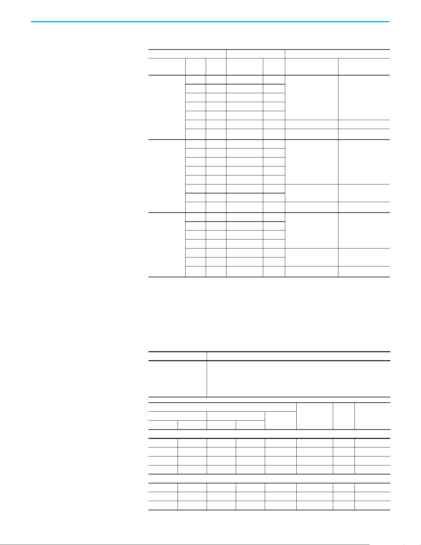
182 Rockwell Automation Publication 520-UM001N-EN-E - July 2024
Appendix B Accessories and Dimensions
Replacement Parts
Mounting Adapter Plate for PowerFlex 40P AC Drive to PowerFlex 520-series
Drive Ratings PowerFlex 40P PowerFlex 520-series
Input Voltage HP kW Catalog No.
Frame
Size
Catalog No.
Catalog No. with
external EMC Filter
(1)
(1) The adapter plate catalogs starting with 25-AP1-Fx are used to replace PowerFlex 4/40/40P IP20 drives with external EMC
filter to PowerFlex 520-series drives with external EMC filter only.
200…240V,
3-phase,
50/60 Hz
0.5 0.4 22D-B2P3N104 B
25-AP0-FB 25-AP1-FB
1.0 0.8 22D-B5P0N104 B
2.0 1.5 22D-B8P0N104 B
3.0 2.2 22D-B012N104 B
5.0 3.7 22D-B017N104 B
7.5 5.5 22D-B024N104 C 25-AP0-FC 25-AP1-FC
10.0 7.5 22D-B033N104 C 25-AP0-FD
—
(2)
(2) Mounting Adapter Plate is not required for the following ratings, as it comes with matching footprint and mounting holes.
• 3-phase 200…240V: 7.5 kW/10 HP
• 3-phase 380…480V: 11 kW/15 HP
• 3-phase 500…600V: 11 kW/15 HP
380…480V,
3-phase
50/60 Hz
0.5 0.4 22D-D1P4N104 B
25-AP0-FB 25-AP1-FB
1.0 0.8 22D-D2P3N104 B
2.0 1.5 22D-D4P0N104 B
3.0 2.2 22D-D6P0N104 B
5.0 3.7 22D-D010N104 B
7.5 5.5 22D-D012N104 C
25-AP0-FC 25-AP1-FC
10.0 7.5 22D-D017N104 C
15.0 11.0 22D-D024N104 C 25-AP0-FD
—
(2)
525…600V,
3-phase
50/60 Hz
1.0 0.8 22D-E1P7N104 B
25-AP0-FB 25-AP1-FB
2.0 1.5 22D-E3P0N104 B
3.0 2.2 22D-E4P2N104 B
5.0 3.7 22D-E6P6N104 B
7.5 5.5 22D-E9P9N104 C
25-AP0-FC 25-AP1-FC
10.0 7.5 22D-E012N104 C
15.0 11.0 22D-E019N104 C 25-AP0-FD
—
(2)
PowerFlex 520-series Power Module
Item Description
PowerFlex 520-series
Power Module
Replacement power module for use with PowerFlex 520-series drives. Includes:
• Power Module
• Power Module Front Cover
• Power Terminal Guard
•Heatsink Fan
Output Ratings
Input
Voltage Range
Frame
Size
Catalog No.Normal Duty Heavy Duty
Output
Current (A)
HP kW HP kW
100…120V AC (-15%, +10%) – 1-phase Input, 0…230V 3-phase Output
0.25 0.2 0.25 0.2 1.6 85…132 A 25-PM1-V1P6
0.5 0.4 0.5 0.4 2.5 85…132 A 25-PM1-V2P5
1.0 0.75 1.0 0.75 4.8 85…132 B 25-PM1-V4P8
1.5 1.1 1.5 1.1 6.0 85…132 B 25-PM1-V6P0
200…240V AC (-15%, +10%) – 1-phase Input, 0…230V 3-phase Output
0.25 0.2 0.25 0.2 1.6 170…264 A 25-PM1-A1P6
0.5 0.4 0.5 0.4 2.5 170…264 A 25-PM1-A2P5
1.0 0.75 1.0 0.75 4.8 170…264 A 25-PM1-A4P8

Rockwell Automation Publication 520-UM001N-EN-E - July 2024 183
Appendix B Accessories and Dimensions
2.0 1.5 2.0 1.5 8.0 170…264 B 25-PM1-A8P0
3.0 2.2 3.0 2.2 11.0 170…264 B 25-PM1-A011
200…240V AC (-15%, +10%) – 1-phase Input with EMC Filter, 0…230V 3-phase Output
0.25 0.2 0.25 0.2 1.6 170…264 A 25-PM2-A1P6
0.5 0.4 0.5 0.4 2.5 170…264 A 25-PM2-A2P5
1.0 0.75 1.0 0.75 4.8 170…264 A 25-PM2-A4P8
2.0 1.5 2.0 1.5 8.0 170…264 B 25-PM2-A8P0
3.0 2.2 3.0 2.2 11.0 170…264 B 25-PM2-A011
200…240V AC (-15%, +10%) – 3-phase Input, 0…230V 3-phase Output
0.25 0.2 0.25 0.2 1.6 170…264 A 25-PM1-B1P6
0.5 0.4 0.5 0.4 2.5 170…264 A 25-PM1-B2P5
1.0 0.75 1.0 0.75 5.0 170…264 A 25-PM1-B5P0
2.0 1.5 2.0 1.5 8.0 170…264 A 25-PM1-B8P0
3.0 2.2 3.0 2.2 11.0 170…264 A 25-PM1-B011
5.0 4.0 5.0 4.0 17.5 170…264 B 25-PM1-B017
7.5 5.5 7.5 5.5 24.0 170…264 C 25-PM1-B024
10.0 7.5 10.0 7.5 32.2 170…264 D 25-PM1-B032
15.0 11.0 10.0 7.5 48.3 170…264 E 25-PM1-B048
20.0 15.0 15.0 11.0 62.1 170…264 E 25-PM1-B062
380…480V AC (-15%, +10%) – 3-phase Input, 0…460V 3-phase Output
0.5 0.4 0.5 0.4 1.4 323…528 A 25-PM1-D1P4
1.0 0.75 1.0 0.75 2.3 323…528 A 25-PM1-D2P3
2.0 1.5 2.0 1.5 4.0 323…528 A 25-PM1-D4P0
3.0 2.2 3.0 2.2 6.0 323…528 A 25-PM1-D6P0
5.0 4.0 5.0 4.0 10.5 323…528 B 25-PM1-D010
7.5 5.5 7.5 5.5 13.0 323…528 C 25-PM1-D013
10.0 7.5 10.0 7.5 17.0 323…528 C 25-PM1-D017
15.0 11.0 15.0 11.0 24.0 323…528 D 25-PM1-D024
20.0 15.0 15.0 11.0 30.0 323…528 D 25-PM1-D030
380…480V AC (-15%, +10%) – 3-phase Input with EMC Filter, 0…460V 3-phase Output
0.5 0.4 0.5 0.4 1.4 323…528 A 25-PM2-D1P4
1.0 0.75 1.0 0.75 2.3 323…528 A 25-PM2-D2P3
2.0 1.5 2.0 1.5 4.0 323…528 A 25-PM2-D4P0
3.0 2.2 3.0 2.2 6.0 323…528 A 25-PM2-D6P0
5.0 4.0 5.0 4.0 10.5 323…528 B 25-PM2-D010
7.5 5.5 7.5 5.5 13.0 323…528 C 25-PM2-D013
10.0 7.5 10.0 7.5 17.0 323…528 C 25-PM2-D017
15.0 11.0 15.0 11.0 24.0 323…528 D 25-PM2-D024
20.0 15.0 15.0 11.0 30.0 323…528 D 25-PM2-D030
25.0 18.5 20.0 15.0 37.0 323…528 E 25-PM2-D037
30.0 22.0 25.0 18.5 43.0 323…528 E 25-PM2-D043
525…600V AC (-15%, +10%) – 3-phase Input, 0…575V 3-phase Output
0.5 0.4 0.5 0.4 0.9 446…660 A 25-PM1-E0P9
1.0 0.75 1.0 0.75 1.7 446…660 A 25-PM1-E1P7
2.0 1.5 2.0 1.5 3.0 446…660 A 25-PM1-E3P0
3.0 2.2 3.0 2.2 4.2 446…660 A 25-PM1-E4P2
5.0 4.0 5.0 4.0 6.6 446…660 B 25-PM1-E6P6
7.5 5.5 7.5 5.5 9.9 446…660 C 25-PM1-E9P9
10.0 7.5 10.0 7.5 12.0 446…660 C 25-PM1-E012
15.0 11.0 15.0 11.0 19.0 446…660 D 25-PM1-E019
Output Ratings (Continued)
Input
Voltage Range
Frame
Size
Catalog No.Normal Duty Heavy Duty
Output
Current (A)
HP kW HP kW

184 Rockwell Automation Publication 520-UM001N-EN-E - July 2024
Appendix B Accessories and Dimensions
20.0 15.0 15.0 11.0 22.0 446…660 D 25-PM1-E022
25.0 18.5 20.0 15.0 27.0 446…660 E 25-PM1-E027
30.0 22.0 25.0 18.5 32.0 446…660 E 25-PM1-E032
PowerFlex 520-series Control Module
Item Description
Frame
Size
Catalog No.
PowerFlex 523 Control
Module
Replacement control module for use with
PowerFlex 520-series drives. Includes:
• Control Module
• Control Module Front Cover
A…E
25A-CTM1
PowerFlex 525 Control
Module
25B-CTM1
Other Parts
Item Description
Frame
Size
Catalog No.
PowerFlex 523 Control
Module Front Cover
Replacement cover for the control module I/O terminals,
EtherNet/IP, and DSI ports.
A…E
25A-CTMFC1
PowerFlex 525 Control
Module Front Cover
25B-CTMFC1
PowerFlex 520-series
Power Module Front Cover
Replacement cover for the PowerFlex 520-series power
module
B25-PMFC-FB
C25-PMFC-FC
D25-PMFC-FD
E25-PMFC-FE
PowerFlex 520-series
Power Terminal Guard
Replacement finger guard for power terminals
A25-PTG1-FA
B25-PTG1-FB
C25-PTG1-FC
D25-PTG1-FD
E25-PTG1-FE
PowerFlex 520-series
Heatsink Fan Kit
Replacement fan for drive power module
A 25-FAN1-FA
B 25-FAN1-FB
C 25-FAN1-FC
D 25-FAN1-FD
E 25-FAN1-FE
PowerFlex 520-series EMC
Cores
Replacement EMC cores
A
25-CORE-A
25-CORE-RF-A
B
25-CORE-B
25-CORE-RF-B
C
25-CORE-C
25-CORE-RF-C
D
25-CORE-D
25-CORE-RF-D
E
25-CORE-E
25-CORE-RF-E
Output Ratings (Continued)
Input
Voltage Range
Frame
Size
Catalog No.Normal Duty Heavy Duty
Output
Current (A)
HP kW HP kW

Rockwell Automation Publication 520-UM001N-EN-E - July 2024 185
Appendix B Accessories and Dimensions
Communication Option Kits and Accessories
Item Description Catalog No.
Communication Adapters
Embedded communication options for use with the
PowerFlex 520-series drives:
• DeviceNet®
• Dual-port EtherNet/IP
•PROFIBUS DP-V1
•PROFINET
25-COMM-D
25-COMM-E2P
25-COMM-P
25-COMM-PNET2P
Compact I/O™ Module Three channels 1769-SM2
Universal Serial Bus (USB)
Converter Module
Provides serial communication with DF1 protocol for use
with Connected Components Workbench software.
Includes:
• 2 m (6.6 ft) USB cable (1)
• 20-HIM-H10 cable (1)
• 22-HIM-H10 cable (1)
1203-USB
Serial Converter Module
(RS-485 to RS-232)
Provides serial communication with DF1 protocol for use
with Connected Components Workbench software.
Includes:
• DSI to RS-232 serial converter (1)
• 1203-SFC serial cable (1)
• 22-RJ45CBL-C20 cable (1)
22-SCM-232
DSI Cable 2.0 m (6.6 ft) RJ45 to RJ45 cable, male to male connectors. 22-RJ45CBL-C20
Serial Cable
2.0 m (6.6 ft) serial cable with a locking low profile
connector to connect to the serial converter and a 9-pin
subminiature D female connector to connect to a
computer.
1203-SFC
Splitter Cable RJ45 one to two port splitter cable (Modbus only) AK-U0-RJ45-SC1
Terminating Resistors RJ45 120 Ω resistors (2 pieces) AK-U0-RJ45-TR1
Terminal Block RJ45 Two position terminal block (5 pieces) AK-U0-RJ45-TB2P
Programming Software
Item Description
Connected Components
Workbench Software
Windows-based software packages for programming and configuring Allen-Bradley
drives and other Rockwell Automation products.
Compatibility: Microsoft Windows Server 2012
(1)
, Windows Server 2012 R2, Windows
Server 2016
(1)
, Windows Server 2019, Windows 10 IoT Enterprise 2016 LTSB 64-bit,
Windows 10 IoT Enterprise 2019 LTSC, Windows 10, and Windows 11
(2)
All supported operating systems require .NET Framework 3.5 SP1 to be installed.
You can download Connected Components Workbench Standard Edition software for
free at rok.auto/pcdc
.
To purchase Connected Components Workbench Developer Edition software, visit
rok.auto/ccw.
(1) Requires Connected Components Workbench software version 20.01.00 or earlier.
(2) Requires Connected Components Workbench software version 20.01.00 or later.
Bulletin 1321-3R Series Line Reactors
Output Ratings
(1)
Input Line Reactor
(2)(4)
Output Line Reactor
(2)(3)
Normal Duty Heavy Duty
IP00
(Open Style)
IP11
(NEMA/UL Type 1)
IP00
(Open Style)
IP11
(NEMA/UL Type 1)
HP kW HP kW Catalog No. Catalog No. Catalog No. Catalog No.
200…240V 50/60 Hz 1-phase
(4)
0.25 0.2 0.25 0.2 1321-3R4-A 1321-3RA4-A 1321-3R2-D 1321-3RA2-D
0.5 0.4 0.5 0.4 1321-3R8-A 1321-3RA8-A 1321-3R2-D 1321-3RA2-D
1.0 0.75 1.0 0.75 1321-3R8-A 1321-3RA8-A 1321-3R4-A 1321-3RA4-A
2.0 1.5 2.0 1.5 1321-3R18-A 1321-3RA18-A 1321-3R8-A 1321-3RA8-A
3.0 2.2 3.0 2.2 1321-3R18-A 1321-3RA18-A 1321-3R12-A 1321-3RA12-A

186 Rockwell Automation Publication 520-UM001N-EN-E - July 2024
Appendix B Accessories and Dimensions
200…240V 50/60 Hz 3-phase
0.25 0.2 0.25 0.2 1321-3R2-D 1321-3RA2-D 1321-3R2-D 1321-3RA2-D
0.5 0.4 0.5 0.4 1321-3R2-D 1321-3RA2-D 1321-3R2-D 1321-3RA2-D
1.0 0.75 1.0 0.75 1321-3R4-A 1321-3RA4-A 1321-3R4-A 1321-3RA4-A
2.0 1.5 2.0 1.5 1321-3R8-A 1321-3RA8-A 1321-3R8-A 1321-3RA8-A
3.0 2.2 3.0 2.2 1321-3R12-A 1321-3RA12-A 1321-3R12-A 1321-3RA12-A
5.0 4.0 5.0 4.0 1321-3R18-A 1321-3RA18-A 1321-3R18-A 1321-3RA18-A
7.5 5.5 7.5 5.5 1321-3R25-A 1321-3RA25-A 1321-3R25-A 1321-3RA25-A
10.0 7.5 10.0 7.5 1321-3R35-A 1321-3RA35-A 1321-3R35-A 1321-3RA35-A
15.0 11.0 10.0 7.5 1321-3R45-A 1321-3RA45-A 1321-3R45-A 1321-3RA45-A
20.0 15.0 15.0 11.0
1321-3R55-A (ND)
1321-3R45-A (HD)
1321-3RA55-A (ND)
1321-3RA45-A (HD)
1321-3R55-A (ND)
1321-3R45-A (HD)
1321-3RA55-A (ND)
1321-3RA45-A (HD)
380…480V 50/60 Hz 3-phase
0.5 0.4 0.5 0.4 1321-3R2-B 1321-3RA2-B 1321-3R2-B 1321-3RA2-B
1.0 0.75 1.0 0.75 1321-3R4-C 1321-3RA4-C 1321-3R4-C 1321-3RA4-C
2.0 1.5 2.0 1.5 1321-3R4-B 1321-3RA4-B 1321-3R4-B 1321-3RA4-B
3.0 2.2 3.0 2.2 1321-3R8-C 1321-3RA8-C 1321-3R8-C 1321-3RA8-C
5.0 4.0 5.0 4.0 1321-3R12-B 1321-3RA12-B 1321-3R12-B 1321-3RA12-B
7.5 5.5 7.5 5.5 1321-3R12-B 1321-3RA12-B 1321-3R12-B 1321-3RA12-B
10.0 7.5 10.0 7.5 1321-3R18-B 1321-3RA18-B 1321-3R18-B 1321-3RA18-B
15.0 11.0 15.0 11.0 1321-3R25-B 1321-3RA25-B 1321-3R25-B 1321-3RA25-B
20.0 15.0 15.0 11.0
1321-3R35-B (ND)
1321-3R25-B (HD)
1321-3RA35-B (ND)
1321-3RA25-B (HD)
1321-3R35-B (ND)
1321-3R25-B (HD)
1321-3RA35-B (ND)
1321-3RA25-B (HD)
25.0 18.5 20.0 15.0 1321-3R35-B 1321-3RA35-B 1321-3R35-B 1321-3RA35-B
30.0 22.0 25.0 18.5
1321-3R45-B (ND)
1321-3R35-B (HD)
1321-3RA45-B (ND)
1321-3RA35-B (HD)
1321-3R45-B (ND)
1321-3R35-B (HD)
1321-3RA45-B (ND)
1321-3RA35-B (HD)
525…600V 50/60 Hz 3-phase
0.5 0.4 0.5 0.4 1321-3R1-C 1321-3RA1-C 1321-3R1-C 1321-3RA1-C
1.0 0.75 1.0 0.75 1321-3R2-B 1321-3RA2-B 1321-3R2-B 1321-3RA2-B
2.0 1.5 2.0 1.5 1321-3R4-C 1321-3RA4-C 1321-3R4-C 1321-3RA4-C
3.0 2.2 3.0 2.2 1321-3R4-B 1321-3RA4-B 1321-3R4-B 1321-3RA4-B
5.0 4.0 5.0 4.0 1321-3R8-C 1321-3RA8-C 1321-3R8-C 1321-3RA8-C
7.5 5.5 7.5 5.5 1321-3R12-B 1321-3RA12-B 1321-3R12-B 1321-3RA12-B
10.0 7.5 10.0 7.5 1321-3R12-B 1321-3RA12-B 1321-3R12-B 1321-3RA12-B
15.0 11.0 15.0 11.0 1321-3R18-B 1321-3RA18-B 1321-3R18-B 1321-3RA18-B
20.0 15.0 15.0 11.0
1321-3R25-B (ND)
1321-3R18-B (HD)
1321-3RA25-B (ND)
1321-3RA18-B (HD)
1321-3R25-B (ND)
1321-3R18-B (HD)
1321-3RA25-B (ND)
1321-3RA18-B (HD)
25.0 18.5 20.0 15.0
1321-3R35-C (ND)
1321-3R25-C (HD)
1321-3RA35-C (ND)
1321-3RA25-C (HD)
1321-3R35-C (ND)
1321-3R25-C (HD)
1321-3RA35-C (ND)
1321-3RA25-C (HD)
30.0 22.0 25.0 18.5
1321-3R35-C (ND)
1321-3R25-B (HD)
1321-3RA35-C (ND)
1321-3RA25-B (HD)
1321-3R35-C (ND)
1321-3R25-B (HD)
1321-3RA35-C (ND)
1321-3RA25-B (HD)
(1) Normal Duty and Heavy Duty ratings for 15 HP (11 kW) and below are identical except for 200…240V 3-phase 15 HP (11 kW)
drive.
(2) Catalog numbers that are listed are for 3% impedance at 60 Hz. 5% impedance reactor types are also available.
See the 1321 Power Conditioning Products Technical Data, publication 1321-TD001
.
(3) Input line reactors were sized based on the NEC fundamental motor amps. Output line reactors were sized based on the VFD
rated output currents.
(4) Standard 3-phase reactors can be used for 1-phase applications by routing each of the two supply conductors through an
outside coil and leaving the center open.
Bulletin 1321-3R Series Line Reactors (Continued)
Output Ratings
(1)
Input Line Reactor
(2)(4)
Output Line Reactor
(2)(3)
Normal Duty Heavy Duty
IP00
(Open Style)
IP11
(NEMA/UL Type 1)
IP00
(Open Style)
IP11
(NEMA/UL Type 1)
HP kW HP kW Catalog No. Catalog No. Catalog No. Catalog No.
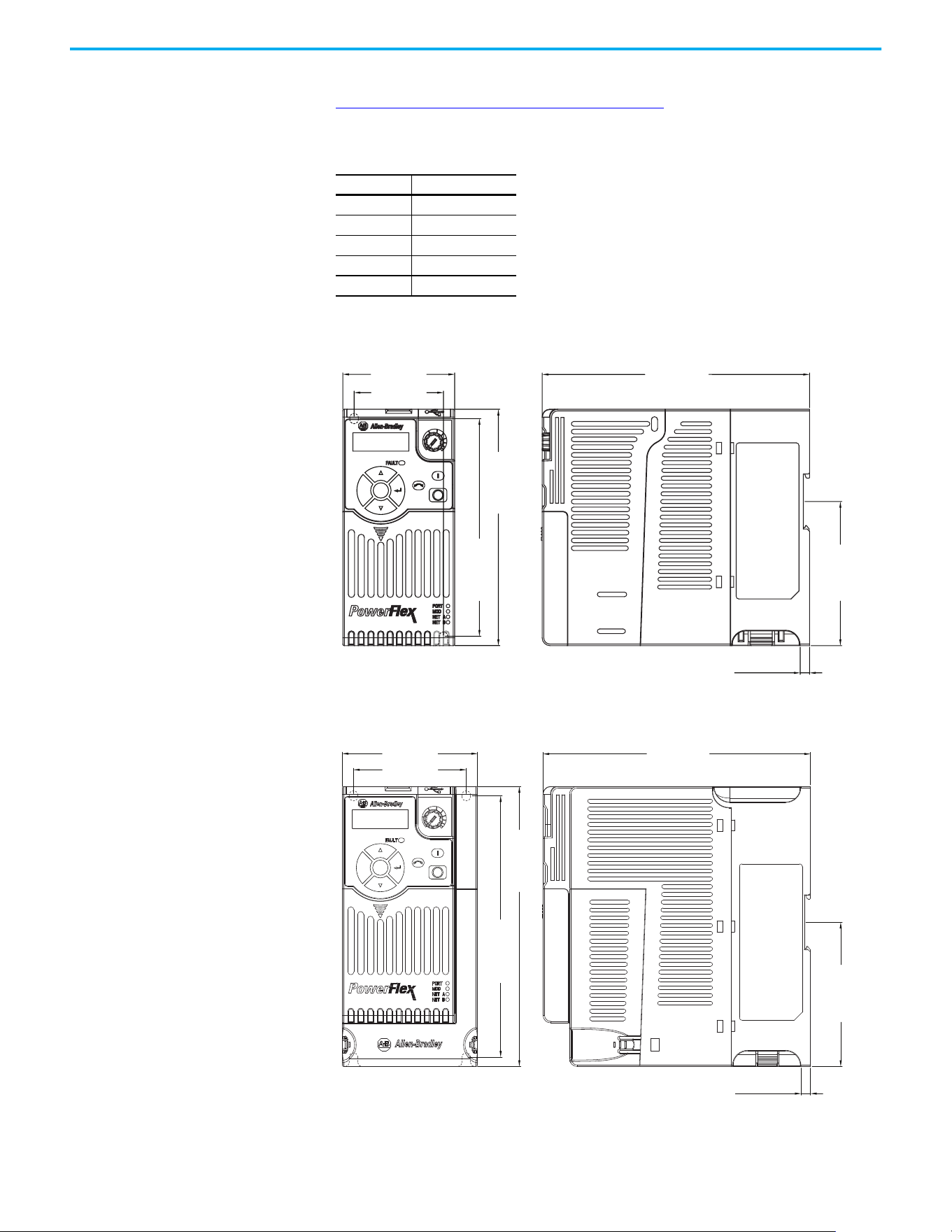
Rockwell Automation Publication 520-UM001N-EN-E - July 2024 187
Appendix B Accessories and Dimensions
Product Dimensions The PowerFlex 520-series drive is available in five frame sizes. See the
PowerFlex 520-series Drive Ratings on page 175
for information on power
ratings.
IP 20/Open Type – Frame A
IP 20/Open Type – Frame B
PowerFlex 520-series Drive Weight
Frame Size Weight (kg/lb)
A1.1 / 2.4
B1.6 / 3.5
C2.3 / 5.0
D3.9 / 8.6
E 12.9 / 28.4
72.0 (2.83)
172.0 (6.77)
6.0 (0.24)
57.5 (2.26)
140.0 (5.51)
152.0 (5.98)
92.7 (3.65)
Esc
Sel
Dimensions are in millimeters and (inches)
Esc
Sel
87.0 (3.43)
172.0 (6.77)
72.5 (2.85)
6.0 (0.24)
180.0 (7.09)
92.7 (3.65)
168.0 (6.61)
Dimensions are in millimeters and (inches)
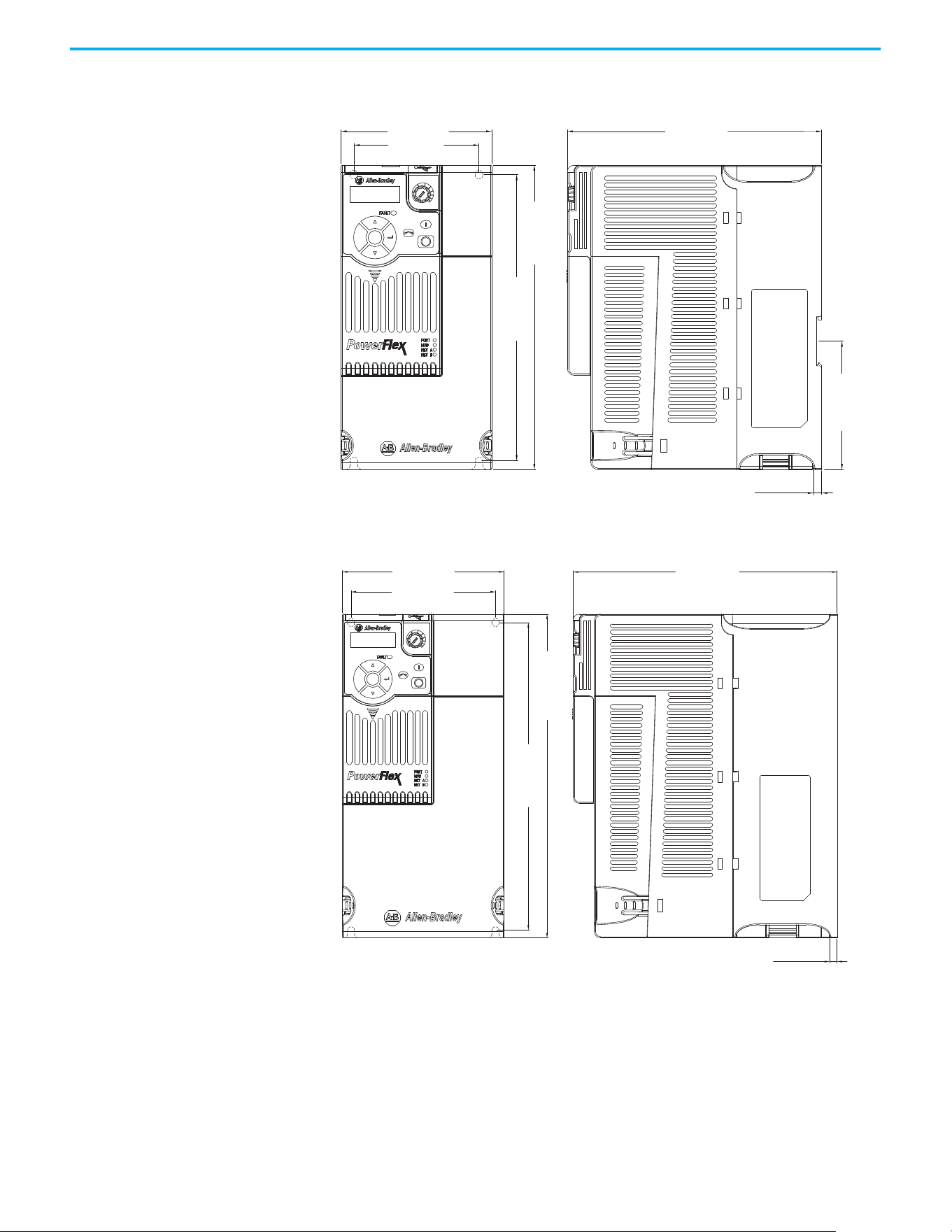
188 Rockwell Automation Publication 520-UM001N-EN-E - July 2024
Appendix B Accessories and Dimensions
IP 20/Open Type – Frame C
IP 20/Open Type – Frame D
Esc
Sel
109.0 (4.29)
90.5 (3.56)
220.0 (8.66)
207.0 (8.15)
184.0 (7.24)
6.0 (0.24)
92.7 (3.65)
Dimensions are in millimeters and (inches)
130.0 (5.12)
260.0 (10.24)
247.0 (9.72)
116.0 (4.57)
212.0 (8.35)
6.0 (0.24)
Esc
Sel
Dimensions are in millimeters and (inches)
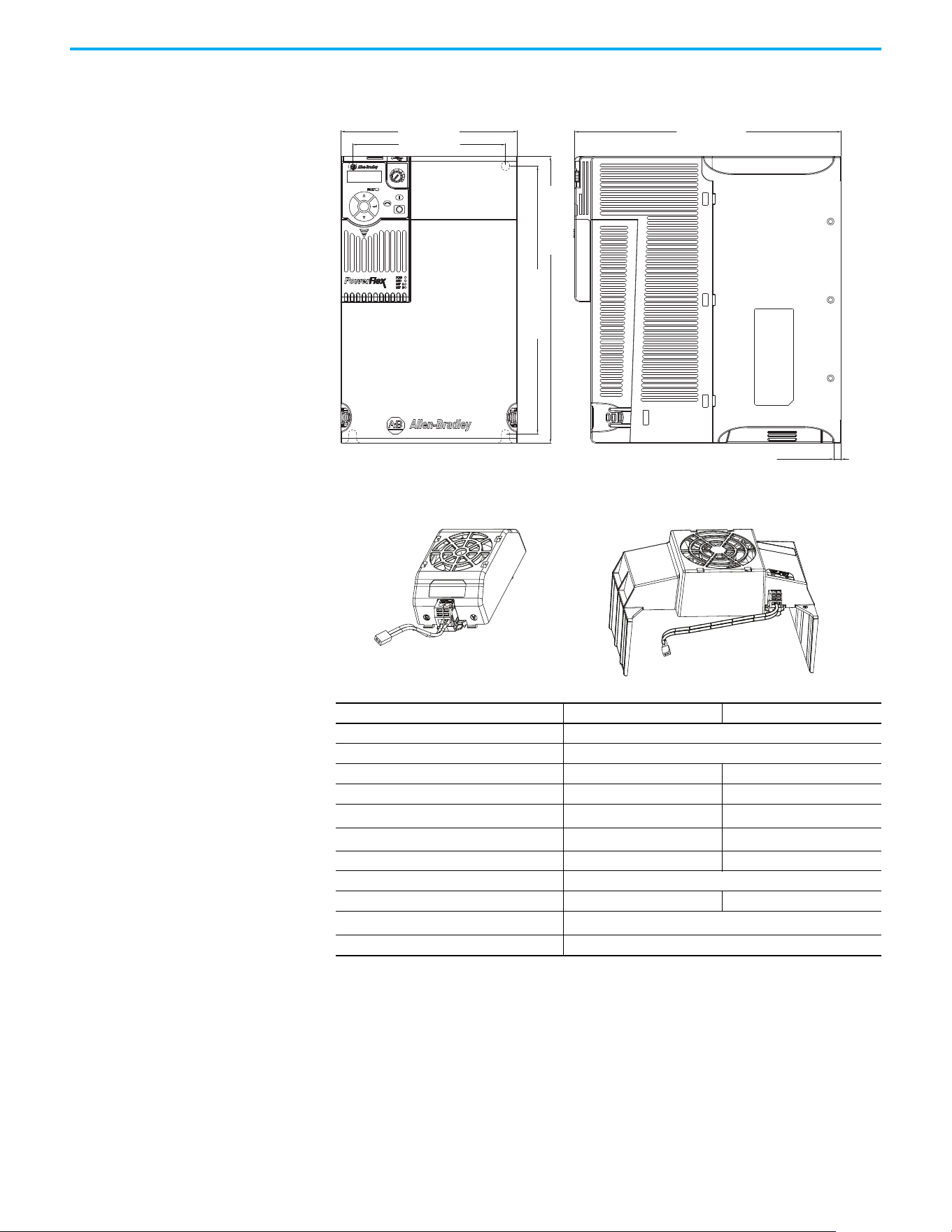
Rockwell Automation Publication 520-UM001N-EN-E - July 2024 189
Appendix B Accessories and Dimensions
IP 20/Open Type – Frame E
Control Module Fan Kit
Specifications 25-FAN1-70C 25-FAN2-70C
Rated Voltage 24V DC
Operation Voltage 14…27.6V DC
Input Current 0.1 A 0.15 A
Speed (Reference) 7000 rpm 4500 ± 10% rpm
Airflow (At zero static pressure) max
0.575 m
3
/min 1.574 m
3
/min
Air Pressure (At zero airflow) min
7.70 mm H
2
O 9.598 mm H
2
O
Acoustical Noise 40.5 dB-A 46.0 dB-A
Insulation Type UL Class A
Frame Size Frame A…D Frame E
Wire Size
0.32 mm
2
(22 AWG)
Torque 0.29…0.39 N•m (2.6…3.47 lb•in)
Esc
Sel
185.0 (7.28)
160.0 (6.30)
300.0 (11.81)
280.0 (11.02)
279.0 (10.98)
7.6 (0.30)
Dimensions are in millimeters and (inches)
25-FAN1-70C 25-FAN2-70C
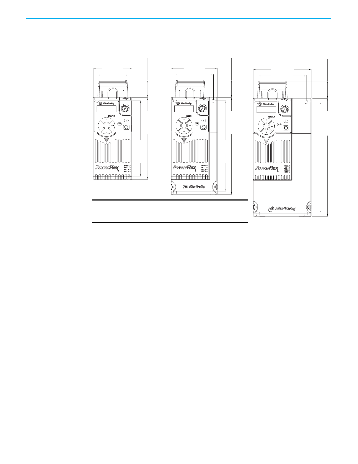
190 Rockwell Automation Publication 520-UM001N-EN-E - July 2024
Appendix B Accessories and Dimensions
IP 20/Open Type with Control Module Fan Kit – Frame A…C
Esc
Sel
72.0 (2.83)
32.0 (1.26)
140.0 (5.51)
152.0 (5.98)
57.5 (2.26)
Esc
Sel
87.0 (3.43)
32.0 (1.26)
180.0 (7.09)
168.0 (6.61)
72.5 (2.85)
Esc
Sel
109.0 (4.29)
32.0 (1.26)
220.0 (8.66)
207.0 (8.15)
90.5 (3.56)
Frame A Frame B
Dimensions are in millimeters and (inches)
Frame C
IMPORTANT
An external 24V DC power source is required when
using the Control Module Fan Kit with drive frames
A, B, and C.
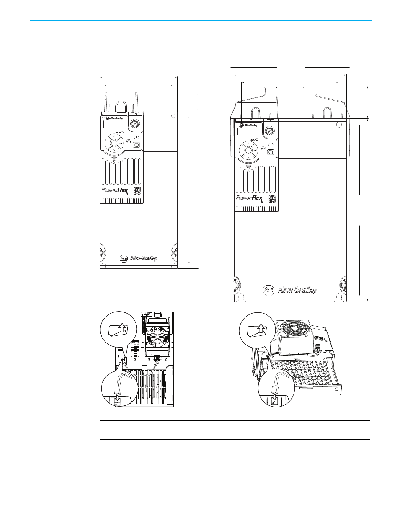
Rockwell Automation Publication 520-UM001N-EN-E - July 2024 191
Appendix B Accessories and Dimensions
IP 20/Open Type with Control Module Fan Kit – Frame D…E
Esc
Sel
130.0 (5.12)
32.0 (1.26)
260.0 (10.24)
247.0 (9.72)
116.0 (4.57)
Esc
Sel
185.0 (7.28)
196.0 (7.72)
52.0 (2.05)
300.0 (11.81)
280.0 (11.02)
160.0 (6.30)
Dimensions are in millimeters and (inches)
Frame D Frame E
IMPORTANT
Remove the label to access the built-in 24V supply on drive frames D and E for use with
the Control Module Fan Kit.
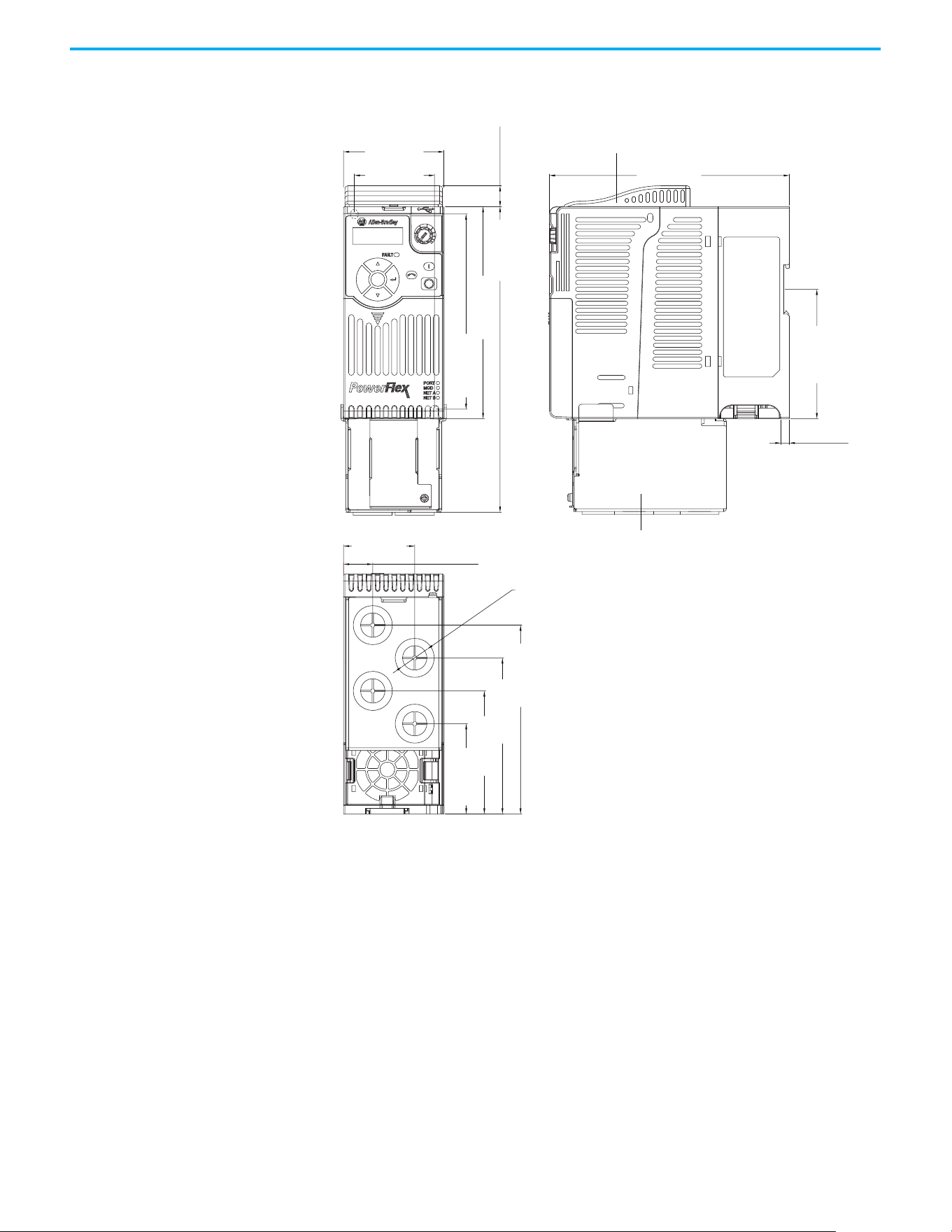
192 Rockwell Automation Publication 520-UM001N-EN-E - July 2024
Appendix B Accessories and Dimensions
IP 30/NEMA 1/UL Type 1 – Frame A
Esc
Sel
72.0 (2.83)
172.0 (6.77)
6.0 (0.24)
51.1 (2.01)
21.0 (0.82)
57.5 (2.26)
15.0 (0.59)
219.0 (8.62)
92.7 (3.65)
140.0 (5.51)
135.4 (5.33)
111.9 (4.41)
88.2 (3.47)
64.7 (2.55)
152.0 (5.98)
ø21.5 (ø0.85)
Dimensions are in millimeters and (inches)
IP 30/NEMA 1/ UL Type 1 conduit box
IP 30/NEMA 1/ UL Type 1 top panel
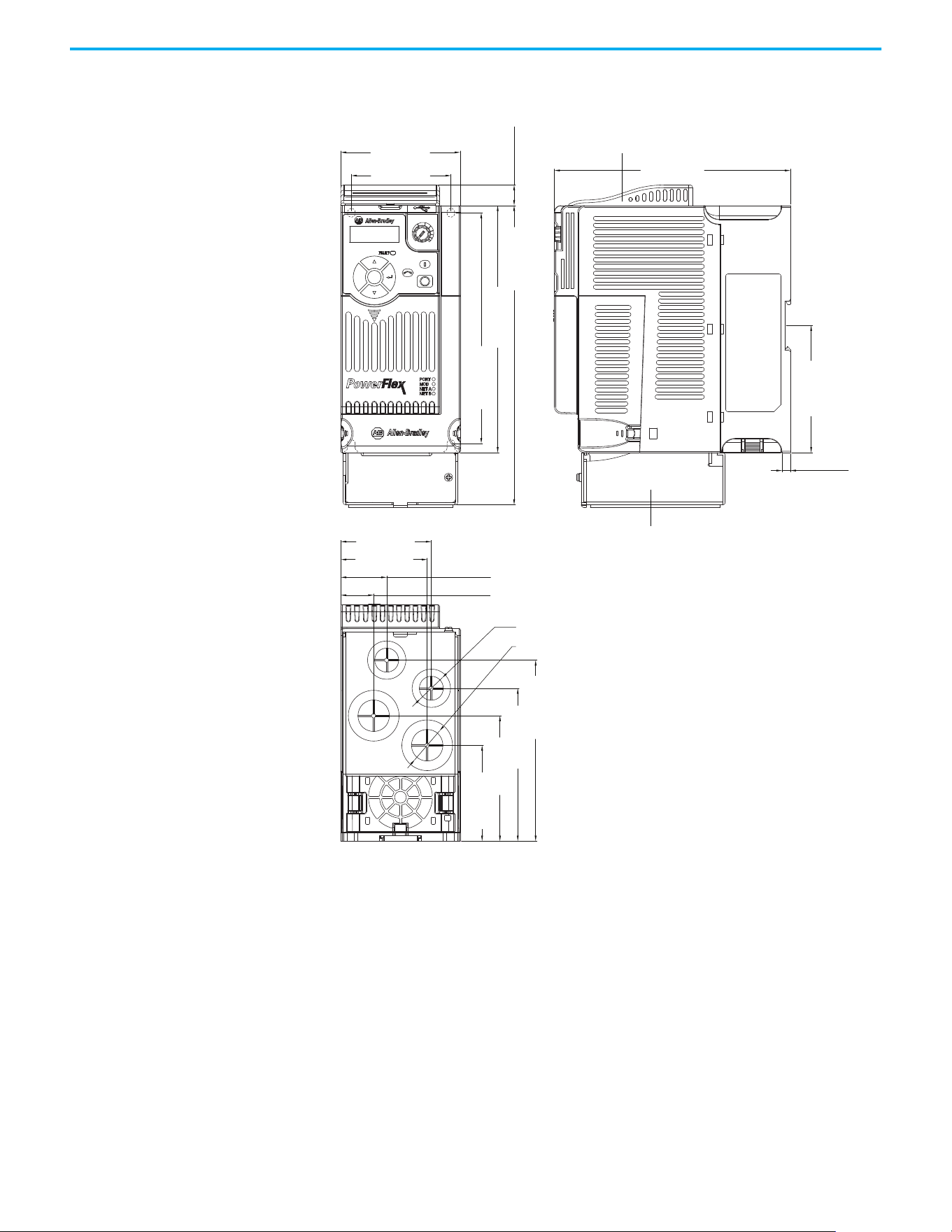
Rockwell Automation Publication 520-UM001N-EN-E - July 2024 193
Appendix B Accessories and Dimensions
IP 30/NEMA 1/UL Type 1 – Frame B
Esc
Sel
87.0 (3.43)
172.0 (6.77)
6.1 (0.24)
72.5 (2.85)
66.1 (2.60)
63.1 (2.48)
33.5 (1.32)
23.9 (0.94)
15.0 (0.59)
92.7 (3.65)
218.0 (8.58)
180.0 (7.09)
168.0 (6.61)
128.5 (5.06)
108.5 (4.27)
88.3 (3.48)
67.3 (2.65)
ø21.5 (ø0.85)
ø27.5 (ø1.08)
Dimensions are in millimeters and (inches)
IP 30/NEMA 1/ UL Type 1 conduit box
IP 30/NEMA 1/ UL Type 1 top panel
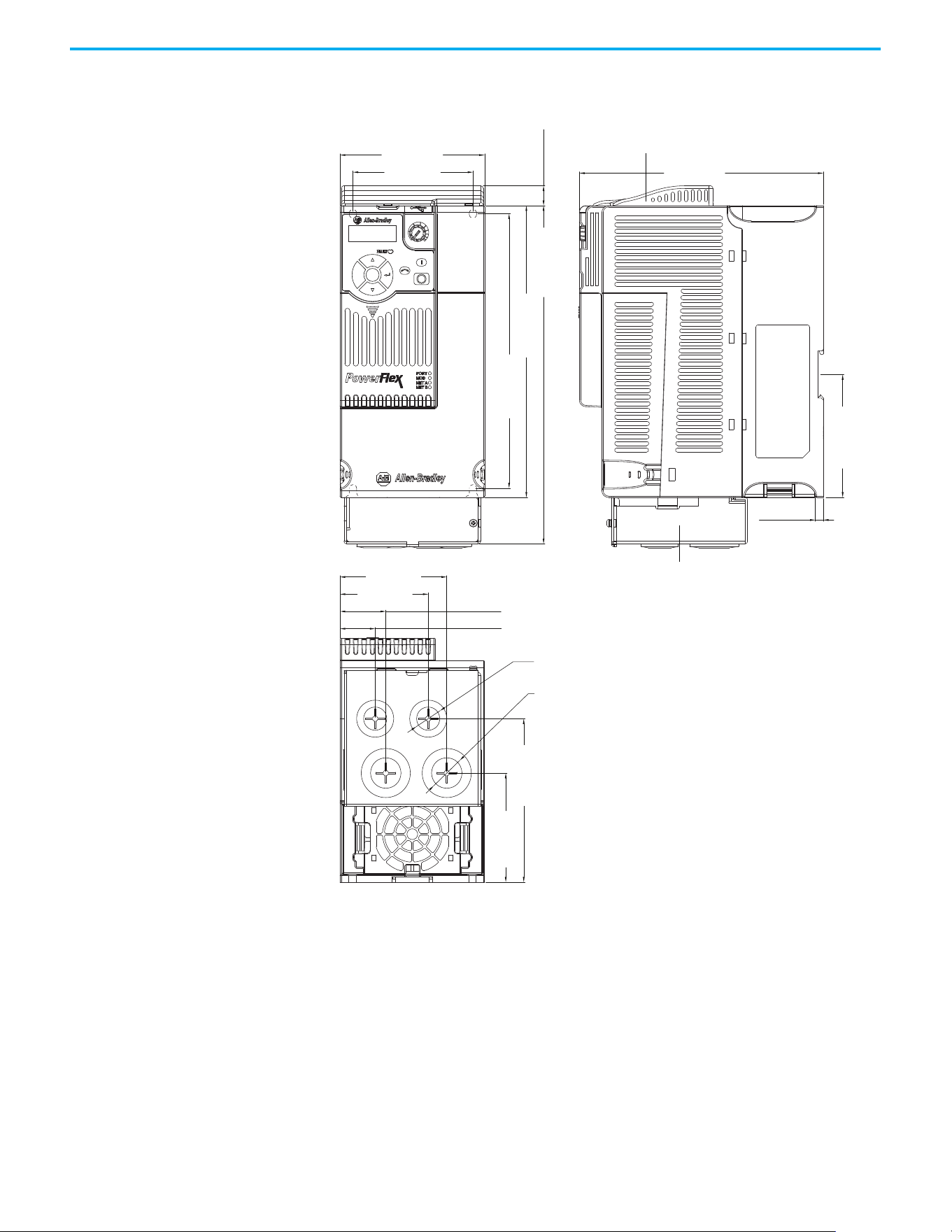
194 Rockwell Automation Publication 520-UM001N-EN-E - July 2024
Appendix B Accessories and Dimensions
IP 30/NEMA 1/UL Type 1 – Frame C
Esc
Sel
109.0 (4.29)
184.0 (7.24)
15.0 (0.59)
207.0 (8.15)
123.3 (4.85)
82.2 (3.24)
222.0 (8.66)
92.7 (3.65)
255.0 (10.04)
90.5 (3.56)
80.5 (3.17)
66.5 (2.62)
34.5 (1.36)
26.5 (1.04)
6.0 (0.24)
ø21.5 (ø0.85)
ø27.5 (ø1.08)
Dimensions are in millimeters and (inches)
IP 30/NEMA 1/ UL Type 1 conduit box
IP 30/NEMA 1/ UL Type 1 top panel
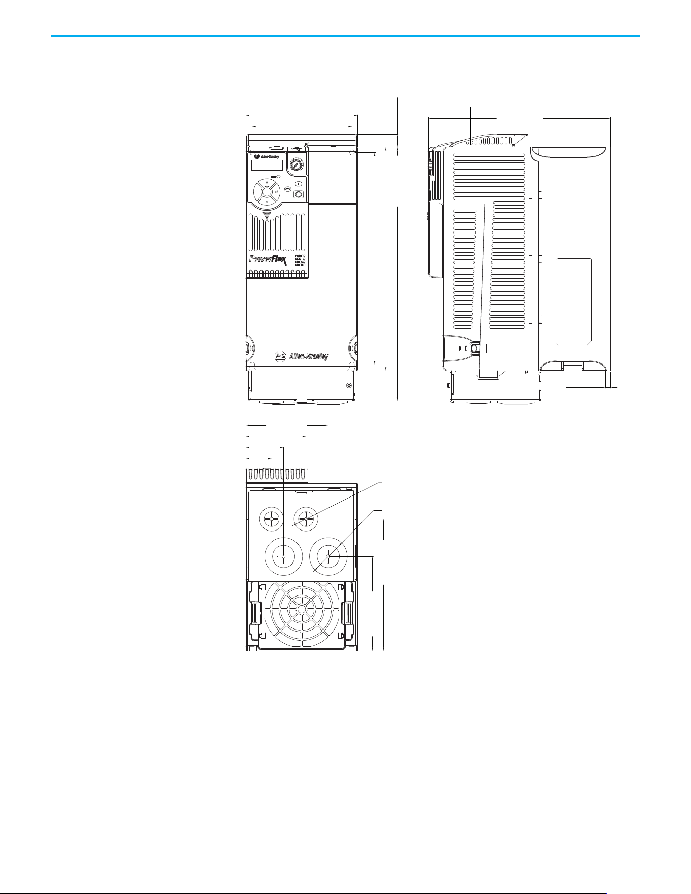
Rockwell Automation Publication 520-UM001N-EN-E - July 2024 195
Appendix B Accessories and Dimensions
IP 30/NEMA 1/UL Type 1 – Frame D
Esc
Sel
130.0 (5.12)
212.0 (8.35)
6.0 (0.24)
260.0 (10.24)
295.0 (11.61)
15.0 (0.59)
247.0 (9.72)
109.8 (4.32)
153.3 (6.04)
116.0 (4.57)
96.0 (3.78)
44.0 (1.73)
30.0 (1.18)
70.0 (2.76)
ø21.5 (ø0.85)
ø33.5 (ø1.32)
Dimensions are in millimeters and (inches)
IP 30/NEMA 1/ UL Type 1 conduit box
IP 30/NEMA 1/ UL Type 1 top panel
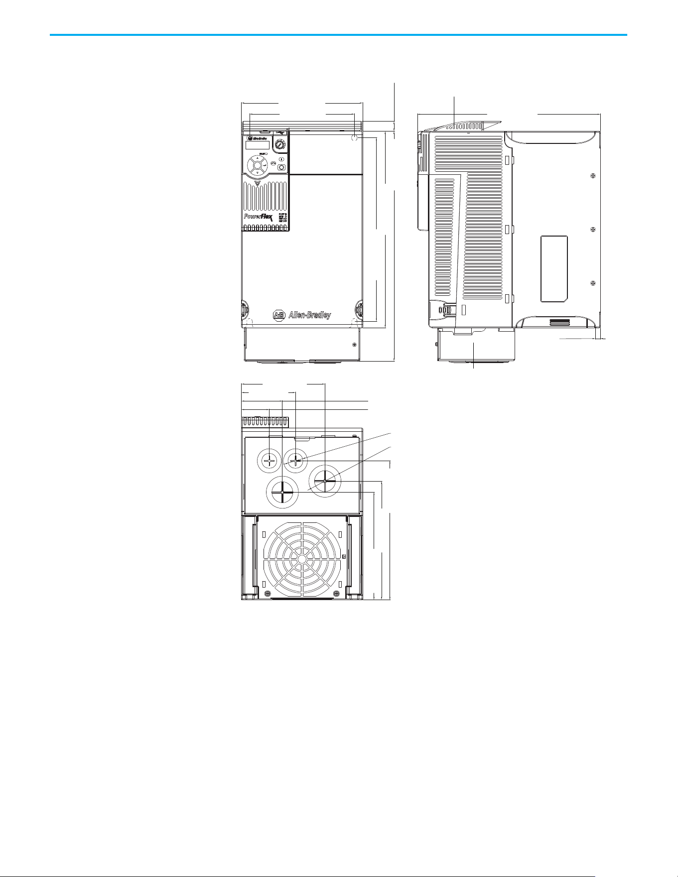
196 Rockwell Automation Publication 520-UM001N-EN-E - July 2024
Appendix B Accessories and Dimensions
IP 30/NEMA 1/UL Type 1 – Frame E
Esc
Sel
185.0 (7.28)
160.0 (6.30)
127.5 (5.02)
82.5 (3.25)
62.5 (2.46)
42.5 (1.67)
279.0 (10.98)
15.0 (0.59)
350.0 (13.78)
300.0 (11.81)
280.0 (11.02)
212.0 (8.35)
181.0 (7.13)
164.0 (6.46)
7.6 (0.30)
ø21.5 (ø0.85)
ø43.7 (ø1.72)
Dimensions are in millimeters and (inches)
IP 30/NEMA 1/ UL Type 1 conduit box
IP 30/NEMA 1/ UL Type 1 top panel
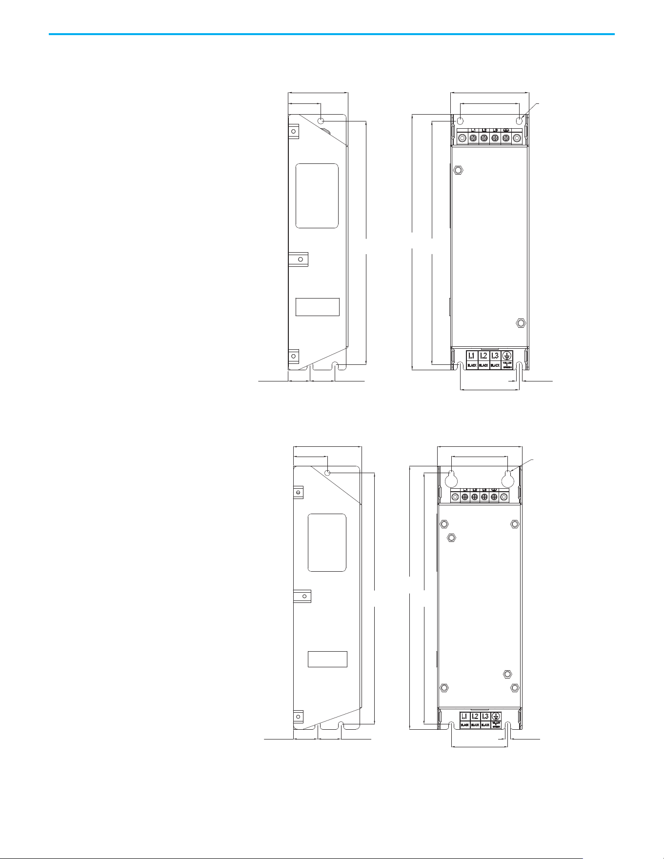
Rockwell Automation Publication 520-UM001N-EN-E - July 2024 197
Appendix B Accessories and Dimensions
EMC Line Filter – Frame A
EMC Line Filter – Frame B
ø5.5 (ø0.22)
72.0 (2.83)
54.0 (2.13)
5.5 (0.22)
54.0 (2.13)
23.0 (0.91)20.0 (0.79)
30.0 (1.18)
55.0 (2.17)
234.0
(9.21)
223.0
(8.78)
223.0
(8.78)
Dimensions are in millimeters and (inches) Filter can be mounted onto the back of the drive.
ø5.5 (ø0.22)
87.0 (3.43)
58.0 (2.28)
270.0
(10.63)
58.0 (2.28)
5.5 (0.22)
258.0
(10.16)
258.0
(10.16)
24.0 (0.94)25.0 (0.98)
35.0 (1.38)
70.0 (2.76)
Dimensions are in millimeters and (inches) Filter can be mounted onto the back of the drive.
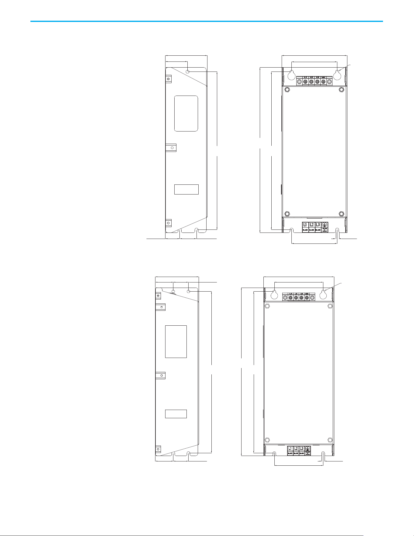
198 Rockwell Automation Publication 520-UM001N-EN-E - July 2024
Appendix B Accessories and Dimensions
EMC Line Filter – Frame C
EMC Line Filter – Frame D
ø5.5 (ø0.22)
263.0
(10.35)
263.0
(10.35)
25.0 (0.98) 28.0 (1.10)
76.0 (2.99)
5.5 (0.22)
275.0
(10.83)
109.0 (4.29)
70.0 (2.76)
76.0 (2.99)
37.0 (1.46)
Dimensions are in millimeters and (inches) Filter can be mounted onto the back of the drive.
ø5.5 (ø0.22)
80.0 (3.15)
130.0 (5.12)
90.0 (3.54)
33.0 (1.30)
33.0 (1.30)
28.0 (1.10)
28.0 (1.10)
298.0
(11.73)
298.0
(11.73)
310.0
(12.20)
90.0 (3.54)
5.5 (0.22)
Dimensions are in millimeters and (inches) Filter can be mounted onto the back of the drive.
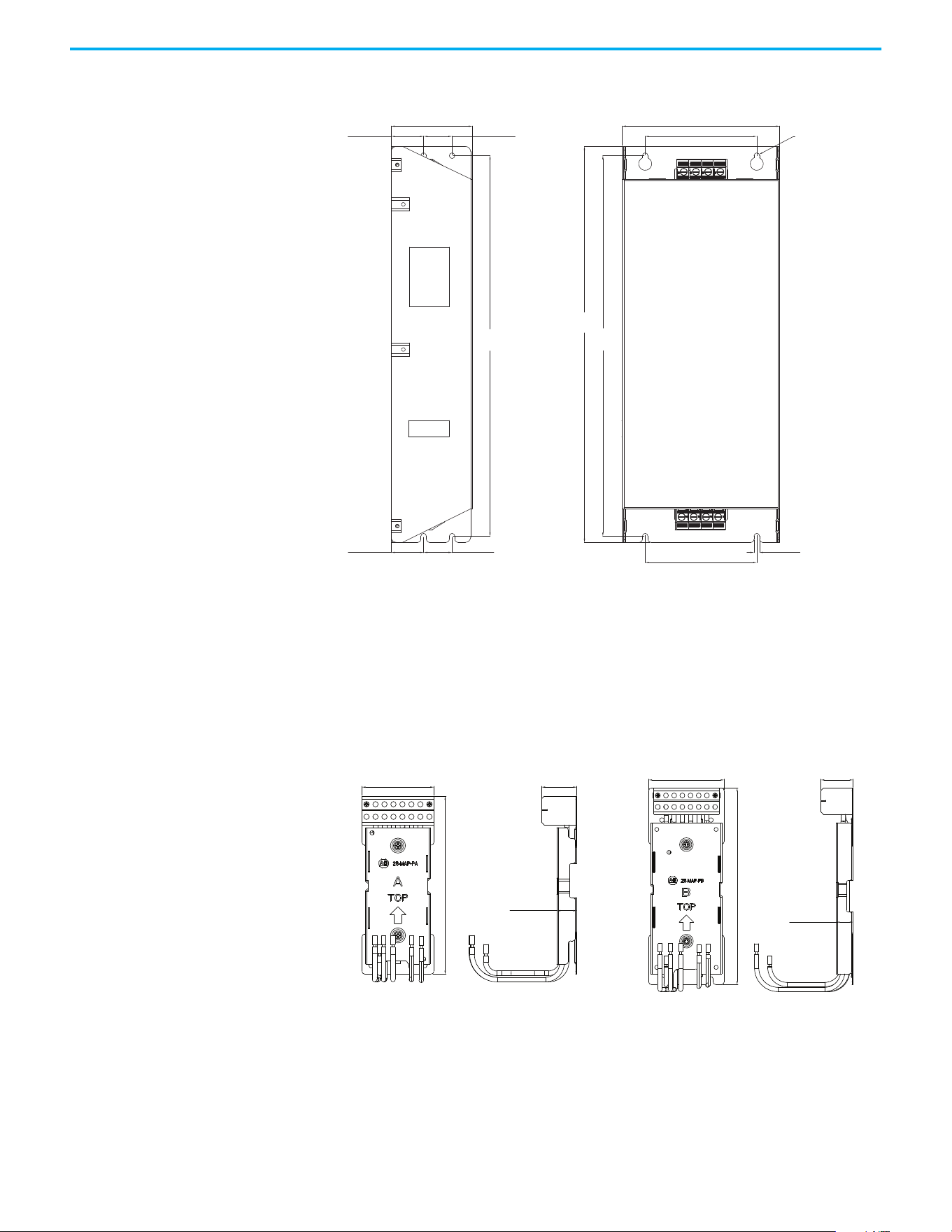
Rockwell Automation Publication 520-UM001N-EN-E - July 2024 199
Appendix B Accessories and Dimensions
EMC Line Filter – Frame E
Adapter Plate Dimensions
Bulletin 160 to PowerFlex 520-series Mounting Adapter Plate Dimensions
80.0 (3.15)
28.0 (1.10)
155.0 (6.10)
110.0 (4.33)
110.0 (4.33)
33.0 (1.30)
28.0 (1.10)33.0 (1.30)
375.0
(14.76)
375.0
(14.76)
390.0
(15.35)
ø5.5 (ø0.22)
5.5 (0.22)
Dimensions are in millimeters and (inches)
Dimensions are in millimeters and (inches)
Frame A
25-MAP-FA
Frame B
25-MAP-FB
80.0 (3.15)
39.2 (1.54)
20.2 (0.80)
198.0 (7.80)
92.0 (3.62)
39.2 (1.54)
20.2 (0.80)
240.0 (9.45)
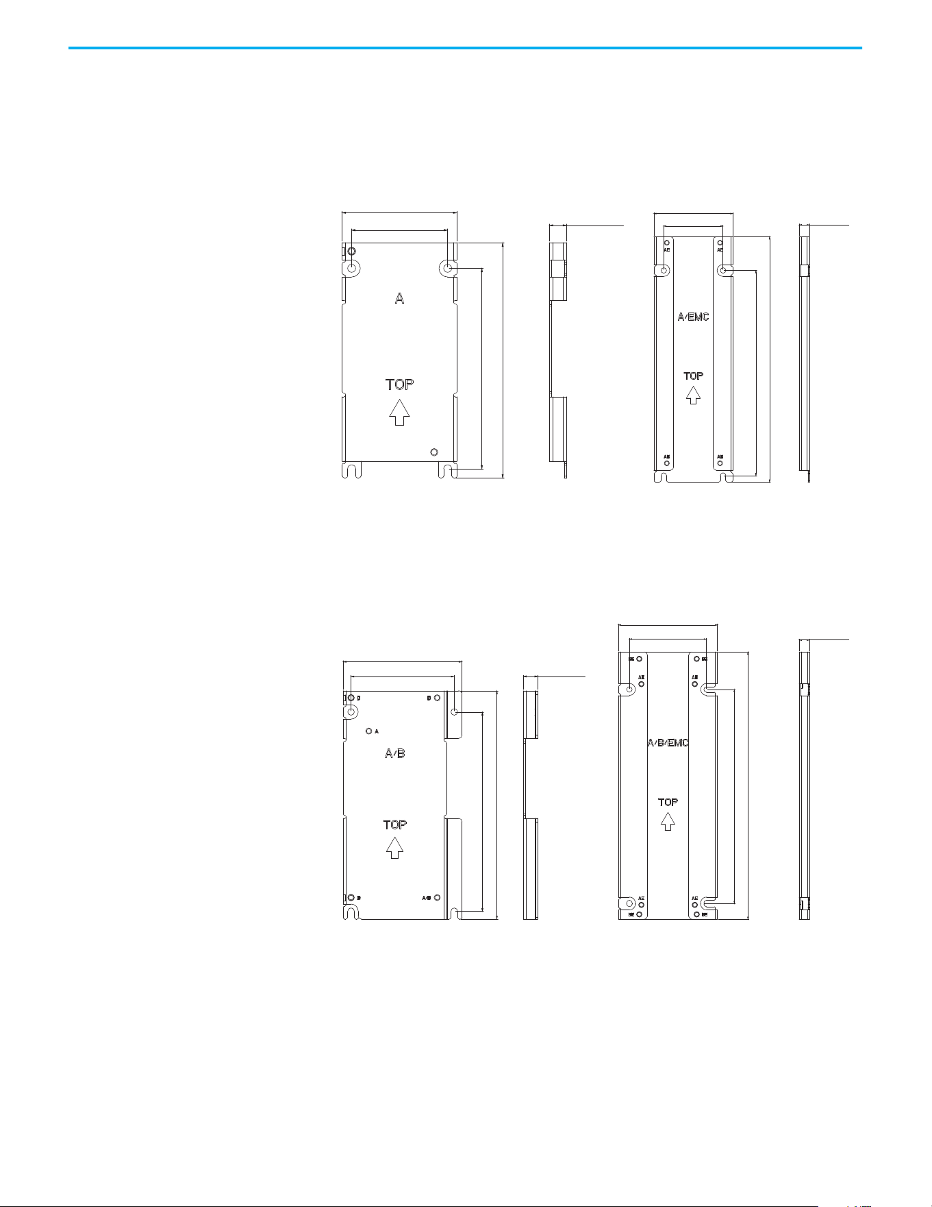
200 Rockwell Automation Publication 520-UM001N-EN-E - July 2024
Appendix B Accessories and Dimensions
PowerFlex 4/40/40P to PowerFlex 520-series Mounting Adapter Plate Dimension
Adapter Plate - Frame A
Adapter Plate - Frame B
Dimensions are in millimeters and (inches)
80.0 (3.15)
164.0 (6.46)
139.5 (5.49)
67.0 (2.64)
12.0 (0.47)
80.0 (3.15)
60.0 (2.36)
248.0 (9.76)
207.5 (8.17)
10.6 (0.42)
Frame A
25-AP0-FA
Frame A
25-AP1-FA
Dimensions are in millimeters and (inches)
100.0 (3.94)
87.0 (3.43)
192.0 (7.56)
167.5 (6.59)
12.0 (0.47)
100.0 (3.94)
78.0 (3.07)
270.0 (10.63)
216.0 (8.50)
10.6 (0.42)
Frame B
25-AP0-FB
Frame B
25-AP1-FB
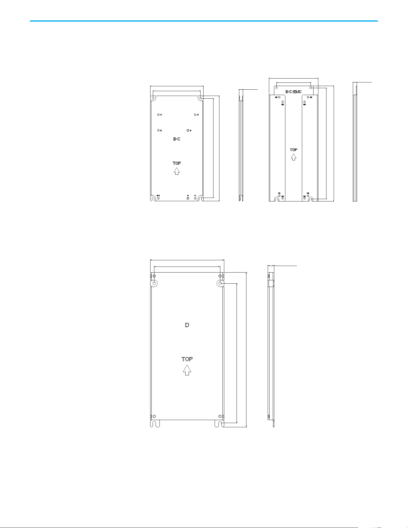
Rockwell Automation Publication 520-UM001N-EN-E - July 2024 201
Appendix B Accessories and Dimensions
Adapter Plate - Frame C
Adapter Plate - Frame D
Dimensions are in millimeters and (inches)
Frame C
25-AP0-FC
Frame C
25-AP1-FC
130.0 (5.12)
116.0 (4.57)
260.0 (10.24)
245.5 (9.67)
9.4 (0.37)
130.0 (5.12)
90.0 (3.54)
296.5 (11.67)
309.0 (12.17)
10.6 (0.42)
Dimensions are in millimeters and (inches)
Frame D
25-AP0-FD
130.0 (5.12)
116.0 (4.57)
272.0 (10.71)
245.5 (9.67)
11.0 (0.43)
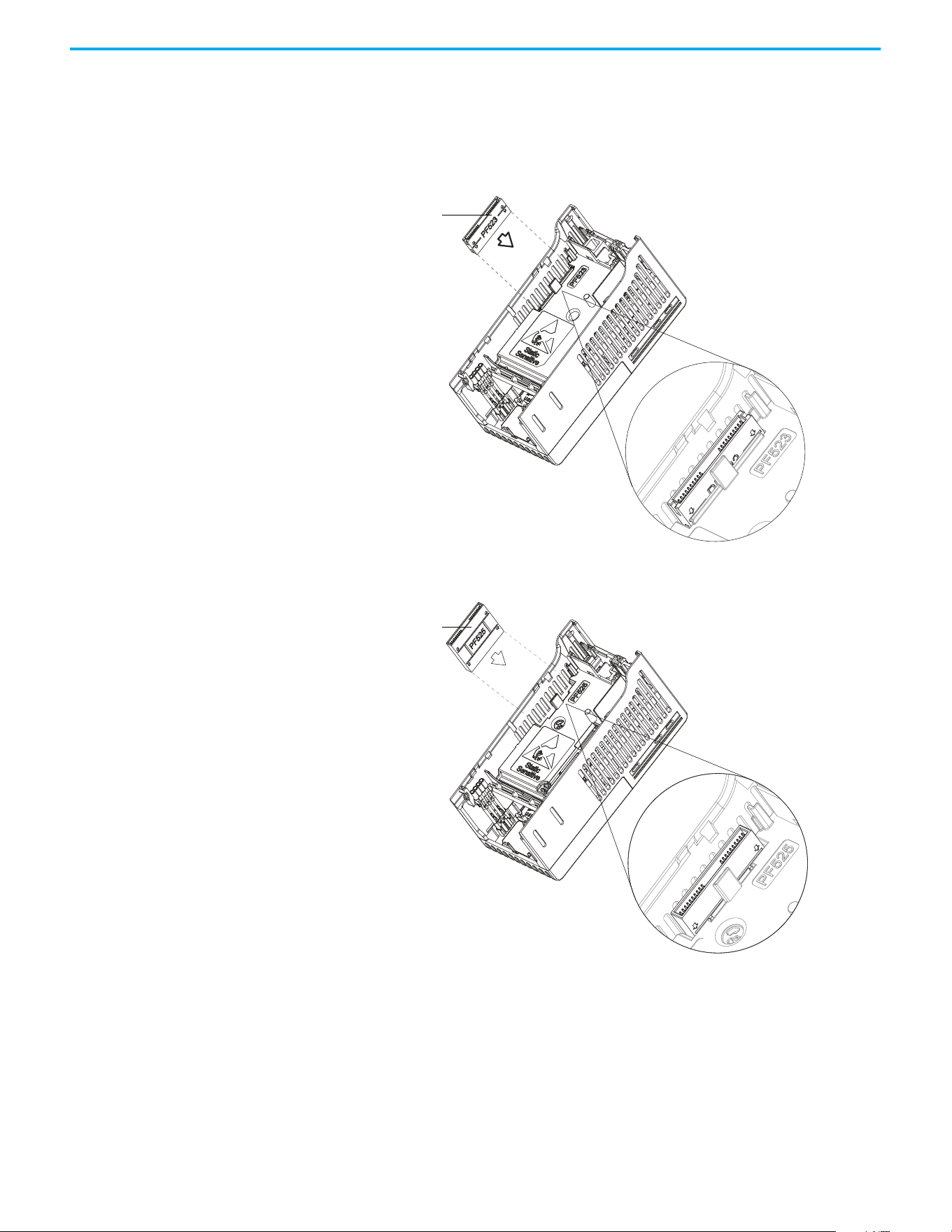
202 Rockwell Automation Publication 520-UM001N-EN-E - July 2024
Appendix B Accessories and Dimensions
Optional Accessories and
Kits
Installing a Communication Adapter
1. Insert the communication adapter interface connector into the Control
Module. Make sure that the indicator line on the connector is aligned
with the surface of the Control Module.
2. Align the connectors on the communication adapter to the
communication adapter interface connector, then push the back cover
down.
Communication
adapter interface
connector
For PowerFlex 523
For PowerFlex 525
Communication
adapter interface
connector
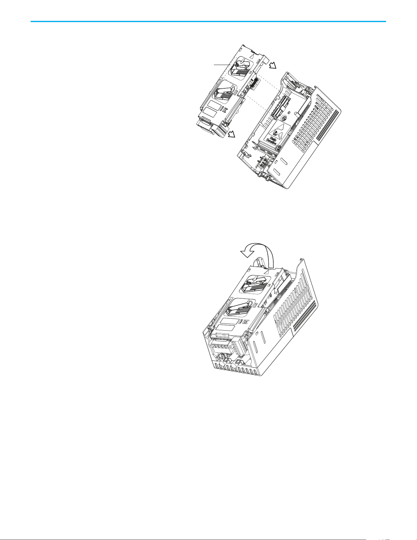
Rockwell Automation Publication 520-UM001N-EN-E - July 2024 203
Appendix B Accessories and Dimensions
3. Press along the edges of the back cover until it snaps firmly into place.
Removing a Communication Adapter
1. Insert a finger into the slot at the top of the back cover. Lift to separate
the back cover from the Control Module.
Communication
adapter interface
connector

204 Rockwell Automation Publication 520-UM001N-EN-E - July 2024
Appendix B Accessories and Dimensions
Notes:
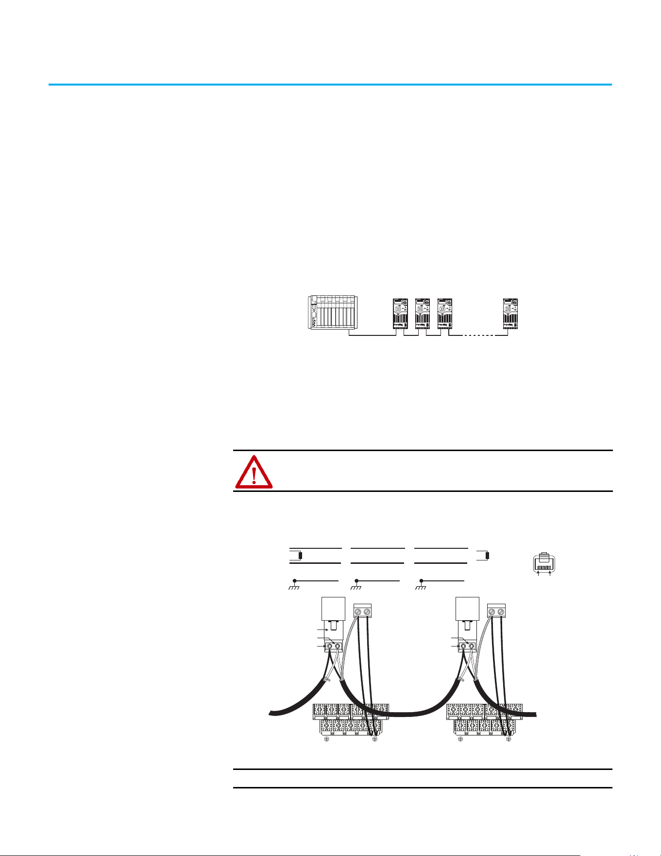
Rockwell Automation Publication 520-UM001N-EN-E - July 2024 205
Appendix C
RS-485 (DSI) Protocol
PowerFlex 520-series drives support the RS-485 (DSI) protocol to allow
efficient operation with Rockwell Automation peripherals. In addition, some
Modbus functions are supported to allow simple networking. PowerFlex 520-
series drives can be multi-dropped on an RS-485 network using Modbus
protocol in RTU mode.
PowerFlex 520-series Drive Network
For information regarding EtherNet/IP or other communication protocols,
refer to the appropriate user manual.
Network Wiring Network wiring consists of a shielded 2-conductor cable that is daisy chained
from node to node.
Network Wiring Diagram Example
Controller
Esc
Sel
Esc
Sel
Esc
Sel
Esc
Sel
ATTENTION: Never attempt to connect a Power over Ethernet (PoE) cable to
the RS-485 port. Doing so may damage the circuitry.
IMPORTANT
The shield is connected at ONLY ONE end of each cable segment.
C1 C2
Master
4
5
TxRxD-
TxRxD+
TxRxD-
TxRxD+
TxRxD-
TxRxD+
Shield Shield Shield
120 ohm resistor
120 ohm resistor
X X X
FRONT
PIN 8PIN 1
TxRxD-
TxRxD+
RS485
(DSI)
AK-U0-RJ45-TB2P
V/T2T/L3S/L2R/L1 U/T1 W/T3
BR+
BR-
DC-
DC+
C1 C2
TxRxD-
TxRxD+
RS485
(DSI)
V/T2T/L3S/L2R/L1 U/T1 W/T3
BR+
BR-
DC-
DC+
PowerFlex 525
Node 1
4
5
PowerFlex 523
Node 2
4
5
PowerFlex 525
Node “n”

206 Rockwell Automation Publication 520-UM001N-EN-E - July 2024
Appendix C RS-485 (DSI) Protocol
Only pins 4 and 5 on the RJ45 plug should be wired. The other pins on the
PowerFlex 520-series drive’s RJ45 socket must not be connected because they
contain power, and so on. for other Rockwell Automation peripheral devices.
Wiring terminations on the master controller will vary depending on the
master controller used and “TxRxD+” and “TxRxD-” are shown for illustration
purposes only. Refer to the master controller’s user manual for network
terminations. Note that there is no standard for the “+” and “-” wires, and
consequently Modbus device manufacturers interpret them differently. If you
have problems with initially establishing communications, try swapping the
two network wires at the master controller.
Standard RS-485 wiring practices apply.
• Termination resistors need to be applied at each end of the network
cable.
• RS-485 repeaters may need to be used for long cable runs, or if greater
than 32 nodes are needed on the network.
• Network wiring should be separated from power wires by at least
0.3 meters (1 foot).
• Network wiring should only cross power wires at a right angle.
I/O Terminal C1 (RJ45 Shield) for the Ethernet and DSI network cables on the
PowerFlex 520-series drive must also be connected to PE ground (there are two
PE terminals on the drive). The shield for the network cables should be
connected to PE ground at one end only.
I/O Terminal C2 (Comm Common) is internally tied to Network Common for
the network signals, and NOT to RJ45 Shield. Tying I/O Terminal C2 to PE
ground may improve noise immunity in some applications.
See I/O Control Terminal Designations on page 40
and page 43 for more
information.
Parameter Configuration The following PowerFlex 520-series drive parameters are used to configure the
drive to operate on a DSI network.
Configuring Parameters for DSI Network
Parameter Details Reference
P046
[Start Source 1] Set to 3 “Serial/DSI” if Start is controlled from the network. page 88
P047 [Speed Reference1]
Set to 3 “Serial/DSI” if the Speed Reference is controlled from the
network.
page 88
C123 [RS485 Data Rate]
Sets the data rate for the RS-485 (DSI) Port. All nodes on the network
must be set to the same data rate.
page 102
C124 [RS485 Node Addr]
Sets the node address for the drive on the network. Each device on the
network requires a unique node address.
page 102
C125 [Comm Loss Action] Selects the drive’s response to communication problems. page 102
C126 [Comm Loss Time]
Sets the time that the drive will remain in communication loss before the
drive implements C125 [Comm Loss Action].
page 102
C127 [Comm Format]
Sets the transmission mode, data bits, parity, and stop bits for the RS-
485 (DSI) Port. All nodes on the network must be set to the same setting.
page 103
C121 [Comm Write Mode]
Set to 0 “Save” when programming drive.
Set to 1 “RAM only” to only write to volatile memory.
page 102

Rockwell Automation Publication 520-UM001N-EN-E - July 2024 207
Appendix C RS-485 (DSI) Protocol
Supported Modbus Function
Codes
The Drive Serial Interface (DSI) used on PowerFlex 520-series drives supports
some of the Modbus function codes.
Writing (06) Logic
Command Data
The PowerFlex 520-series drive can be controlled through the network by
sending Function Code 06 writes to register address 2000H (Logic Command).
P046
[Start Source 1] must be set to 3 “Serial/DSI” in order to accept the
commands. PowerFlex 523 drives support only Velocity bit definitions.
Supported Modbus Function Codes
Modbus Function Code (Decimal) Command
03 Read Holding Registers
06 Preset (Write) Single Register
16 (10 Hexadecimal) Preset (Write) Multiple Registers
IMPORTANT
Modbus devices can be 0-based (registers are numbered starting at 0)
or 1-based (registers are numbered starting at 1). Depending on the
Modbus Master used, the register addresses listed on the following
pages may need to be offset by +1. For example, Logic Command may
be register address 8192 for some master devices (for example, ProSoft
3150-MCM SLC™ Modbus scanner) and 8193 for others (for example,
PanelView™).

208 Rockwell Automation Publication 520-UM001N-EN-E - July 2024
Appendix C RS-485 (DSI) Protocol
PowerFlex 525 drives can use Parameter C122 [Cmd Stat Select] to select either
Velocity or Position bit definitions.
Powerup/Reset the drive after selecting an option for C122 [Cmd Stat
Select] for the change to take effect.
Velocity Bit Definitions
Comm Logic Command – C122 = 0 “Velocity”
Address (Decimal) Bit(s) Description
2000H (8192)
0 1 = Stop, 0 = Not Stop
1 1 = Start, 0 = Not Start
2 1 = Jog, 0 = No Jog
3 1 = Clear Faults, 0 = Not Clear Faults
5, 4
00 = No Command
01 = Forward Command
10 = Reverse Command
11 = No Command
6 1 = Force Keypad Control, 0 = Not Force Keypad Control
7 1 = MOP Increment, 0 = Not Increment
9, 8
00 = No Command
01 = Accel Rate 1 Enable
10 = Accel Rate 2 Enable
11 = Hold Accel Rate Selected
11, 10
00 = No Command
01 = Decel Rate 1 Enable
10 = Decel Rate 2 Enable
11 = Hold Decel Rate Selected
14, 13, 12
000 = No Command
001 = Freq. Source = P047 [Speed Reference1]
010 = Freq. Source = P049 [Speed Reference2]
011 = Freq. Source = P051 [Speed Reference3]
100 = A410 [Preset Freq 0]
101 = A411 [Preset Freq 1]
110 = A412 [Preset Freq 2]
111 = A413 [Preset Freq 3]
15 1 = MOP Decrement, 0 = Not Decrement
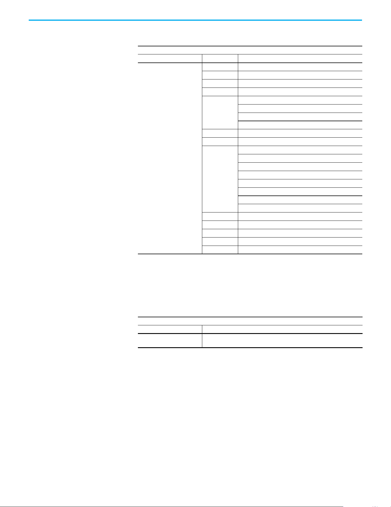
Rockwell Automation Publication 520-UM001N-EN-E - July 2024 209
Appendix C RS-485 (DSI) Protocol
Writing (06) Comm
Frequency Command
The PowerFlex 520-series drive Comm Frequency Command can be controlled
through the network by sending Function Code 06 writes to register address
2001H (Comm Frequency Command).
Position Bit Definitions
Comm Logic Command – C122 = 1 “Position”
Address (Decimal) Bit(s) Description
2000H (8192)
0 1 = Stop, 0 = Not Stop
1 1 = Start, 0 = Not Start
2 1 = Jog, 0 = No Jog
3 1 = Clear Faults, 0 = Not Clear Faults
5, 4
00 = No Command
01 = Forward Command
10 = Reverse Command
11 = No Command
6 1 = Logic In 1
7 1 = Logic In 2
10, 9, 8
000 = Freq. and Position Step 0
001 = Freq. and Position Step 1
010 = Freq. and Position Step 2
011 = Freq. and Position Step 3
100 = Freq. and Position Step 4
101 = Freq. and Position Step 5
110 = Freq. and Position Step 6
111 = Freq. and Position Step 7
11 1 = Find Home
12 1 = Hold Step
13 1 = Pos Redefine
14 1 = Sync Enable
15 1 = Traverse Disable
Comm Frequency Command
Reference
Address (Decimal) Description
2001H (8193)
Used by internal comm modules to control the reference of the drive. In units of
0.01 Hz.
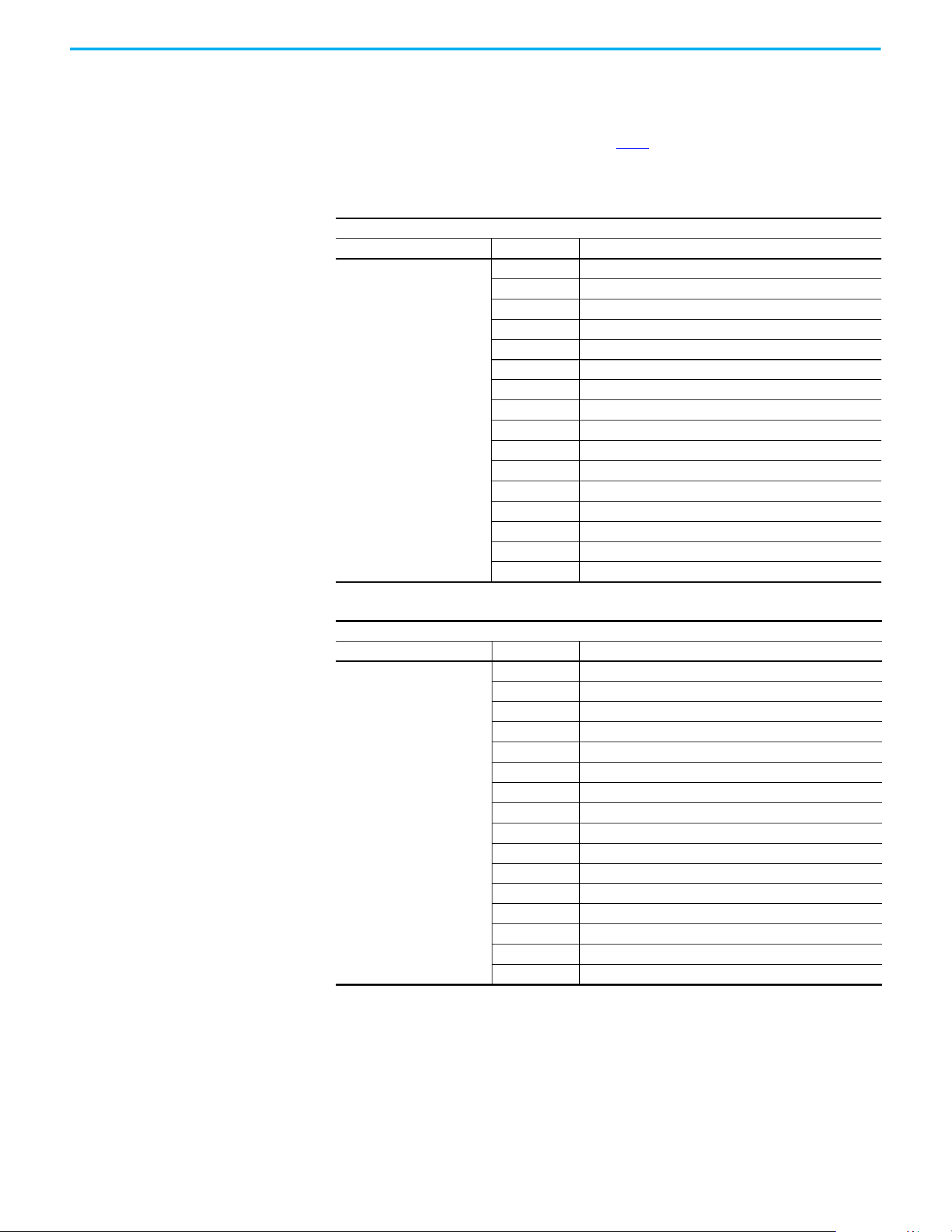
210 Rockwell Automation Publication 520-UM001N-EN-E - July 2024
Appendix C RS-485 (DSI) Protocol
Reading (03) Logic Status
Data
The PowerFlex 520-series drive Logic Status data can be read through the
network by sending Function Code 03 reads to register address 2100H (Logic
Status). PowerFlex 523 drives support only Velocity bit definitions.
PowerFlex 525 drives can use Parameter C122
[Cmd Stat Select] to select either
Velocity or Position bit definitions.
Velocity Bit Definitions
Comm Logic Status – C122 = 0 “Velocity”
Address (Decimal) Bit(s) Description
2100H (8448)
0 1 = Ready, 0 = Not Ready
1 1 = Active (Running), 0 = Not Active
2 1 = Cmd Forward, 0 = Cmd Reverse
3 1 = Rotating Forward, 0 = Rotating Reverse
4 1 = Accelerating, 0 = Not Accelerating
5 1 = Decelerating, 0 = Not Decelerating
6Not Used
7 1 = Faulted, 0 = Not Faulted
8 1 = At Reference, 0 = Not At Reference
9 1 = Main Freq Controlled by Active Comm
10 1 = Operation Cmd Controlled by Active Comm
11 1 = Parameters have been locked
12 Digital Input 1 Status (DigIn TermBlk 05)
13 Digital Input 2 Status (DigIn TermBlk 06)
14 Digital Input 3 Status (DigIn TermBlk 07)
15 Digital Input 4 Status (DigIn TermBlk 08)
Position Bit Definitions
Comm Logic Status – C122 = 1 “Position”
Address (Decimal) Bit(s) Description
2100H (8448)
0 1 = Ready, 0 = Not Ready
1 1 = Active (Running), 0 = Not Active
2 1 = Cmd Forward, 0 = Cmd Reverse
3 1 = Rotating Forward, 0 = Rotating Reverse
4 1 = Accelerating, 0 = Not Accelerating
5 1 = Decelerating, 0 = Not Decelerating
6 1 = Forward Travel Position, 0 = Reverse Travel Position
7 1 = Faulted, 0 = Not Faulted
8 1 = At Reference, 0 = Not At Reference
9 1 = At Position, 0 = Not At Position
10 1 = At Home, 0 = Not At Home
11 1 = Drive Homed, 0 = Not Drive Homed
12 1 = Sync Hold, 0 = Not Sync Hold
13 1 = Sync Ramp, 0 = Not Sync Ramp
14 1 =Traverse On, 0 = Traverse Off
15 1 = Traverse Decel, 0 = Not Traverse Decel

Rockwell Automation Publication 520-UM001N-EN-E - July 2024 211
Appendix C RS-485 (DSI) Protocol
Reading (03) Drive Error
Codes
The PowerFlex 520-series Error Code data can be read through the network by
sending Function Code 03 reads to register address 2101H (Drive Error Codes).
Drive Error Codes
Logic Status
Address (Decimal) Value (Decimal) Description
2101H (8449)
0No Fault
2 Auxiliary Input
3Power Loss
4Undervoltage
5 Overvoltage
6 Motor Stalled
7 Motor Overload
8 Heatsink Overtemperature
9 Control Module Overtemperature
12 HW Overcurrent (300%)
13 Ground Fault
15 Load Loss
21 Output Phase Loss
29 Analog Input Loss
33 Auto Restart Tries
38 Phase U to Ground Short
39 Phase V to Ground Short
40 Phase W to Ground Short
41 Phase UV Short
42 Phase UW Short
43 Phase VW Short
48 Parameters Defaulted
59 Safety Open
63 Software Overcurrent
64 Drive Overload
70 Power Unit Fail
71 DSI Network Loss
72 Option Card Network Loss
73 Embedded EtherNet/IP Adapter Network Loss
80 AutoTune Fail
81 DSI Communication Loss
82 Option Card Communication Loss
83 Embedded EtherNet/IP Adapter Communication Loss
91 Encoder Loss
94 Function Loss
100 Parameter Checksum Error
101 External Storage
105 Control Module Connect Error
106 Incompatible Control-Power Module
107 Unrecognized Control-Power Module
109 Mismatched Control-Power Module
110 Keypad Membrane
111 Safety Hardware
114 Microprocessor Failure
122 I/O Board Fail
2101H (8449)
125 Flash Update Required
126 Non Recoverable Error
127 DSI Flash Update Required

212 Rockwell Automation Publication 520-UM001N-EN-E - July 2024
Appendix C RS-485 (DSI) Protocol
Reading (03) Drive
Operational Values
The PowerFlex 520-series Drive Operational Values can be read through the
network by sending Function Code 03 reads to register addresses
2102H…210AH.
Reading (03) and Writing
(06) Drive Parameters
To access drive parameters, the Modbus register address equals the parameter
number. For example, a decimal “1” is used to address Parameter b001 [Output
Freq] and decimal “41” is used to address Parameter P041 [Accel Time 1].
Additional Information Visit www.rockwellautomation.com/en-us/products/hardware/allen-bradley/
vfd.html for additional information.
Drive Operational Values
Reference
Address (Decimal) Description
2102H (8450) Frequency Command (xxx.xx Hz)
2103H (8451) Output Frequency (xxx.xx Hz)
2104H (8452) Output Current (xxx.xx A)
2105H (8453) DC-BUS Voltage (xxxV)
2106H (8454) Output Voltage (xxx.xV)

Rockwell Automation Publication 520-UM001N-EN-E - July 2024 213
Appendix D
Velocity StepLogic, Basic Logic, and Timer/
Counter Functions
Four PowerFlex 520-series logic functions provide the capability to program
simple logic functions without a separate controller.
• Velocity StepLogic Function (specific to PowerFlex 525 drives only)
Steps through up to eight preset speeds based on programmed logic.
Programmed logic can include conditions that must be met from
digital inputs that are programmed as “Logic In 1” and “Logic In 2”
before stepping from one preset speed to the next. A timer is available
for each of the eight steps and is used to program a time delay before
stepping from one preset speed to the next. The status of a digital
output can also be controlled based on the step being executed.
• Basic Logic Function (specific to PowerFlex 525 drives only)
Up to two digital inputs can be programmed as “Logic In 1” and/or
“Logic In 2”. A digital output can be programmed to change state based
on the condition of one or both inputs based on basic logic functions
such as AND, OR, NOR. The basic logic functions can be used with or
without StepLogic.
•Timer Function
A digital input can be programmed for “Timer Start”. A digital output
can be programmed as a “Timer Out” with an output level that is
programmed to the desired time. When the timer reaches the time
that is programmed into the output level the output changes state. The
timer can be reset with a digital input programmed as “Reset Timer”.
• Counter Function
A digital input can be programmed for “Counter In”. A digital output
can be programmed as “Counter Out” with an output level that is
programmed to the desired number of counts. When the counter
reaches the count that is programmed into the output level the output
changes state. The counter can be reset with a digital input
programmed as “Reset Counter”.
Use the Wizard in Connected Components Workbench software to
simplify setup instead of manually configuring the parameters.
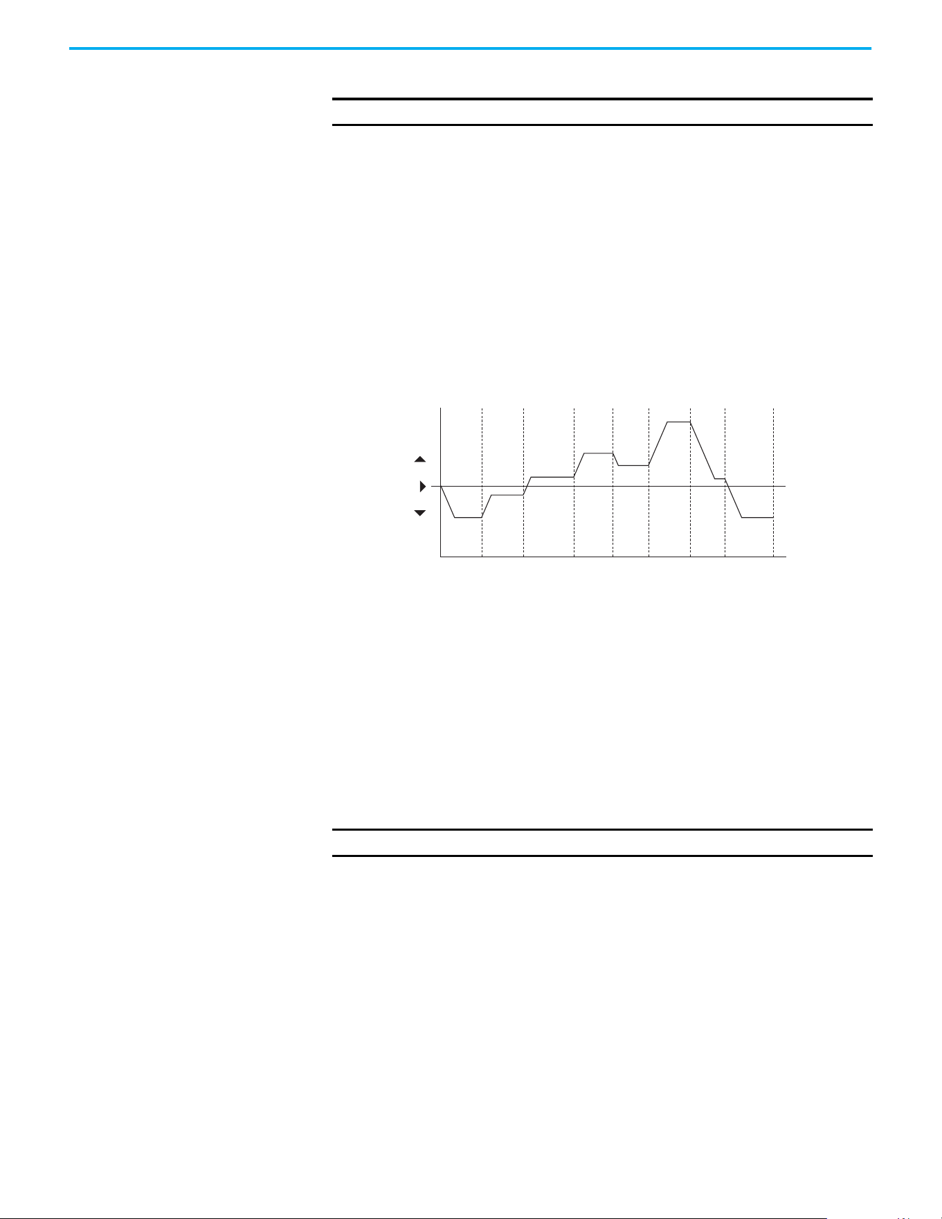
214 Rockwell Automation Publication 520-UM001N-EN-E - July 2024
Appendix D Velocity StepLogic, Basic Logic, and Timer/Counter Functions
Velocity StepLogic Using
Timed Steps
To activate this function, set one of the three speed reference sources,
parameter P047, P049, or P051[Speed Referencex] to 13 “Step Logic” and
activate that speed reference source. Three parameters are used to configure
the logic, speed reference, and time for each step.
• Logic is defined using parameters L180…L187 [Stp Logic x].
• Preset Speeds are set with parameters A410…A417 [Preset Freq 0…7].
• Time of operation for each step is set with parameters L190…L197 [Stp
Logic Time x].
The direction of motor rotation can be forward or reverse.
Using Timed Steps
Velocity StepLogic Sequence
• Sequence begins with a valid start command.
• A normal sequence begins with Step 0 and transition to the next step
when the corresponding StepLogic time has expired.
• Step 7 is followed by Step 0.
• Sequence repeats until a stop is issued or a fault condition occurs.
Velocity StepLogic Using
Basic Logic Functions
Digital input and digital output parameters can be configured to use logic to
transition to the next step. Logic In 1 and Logic In 2 are defined by
programming parameters t062...t063, t065...t068 [DigIn TermBlk xx] to 24
“Logic In 1” or 25 “Logic In 2”.
Example
• Run at Step 0.
• Transition to Step 1 when Logic In 1 is true.
Logic senses the edge of Logic In 1 when it transitions from off to on.
Logic In 1 is not required to remain “on”.
• Transition to Step 2 when both Logic In 1 and Logic In 2 are true.
The drive senses the level of both Logic In 1 and Logic In 2 and transitions
to Step 2 when both are on.
IMPORTANT
This function is specific to PowerFlex 525 drives only.
Time
0
Forward
Reverse
Step 0 Step 1 Step 2 Step 3 Step 4 Step 5 Step 6 Step 7
IMPORTANT
This function is specific to PowerFlex 525 drives only.
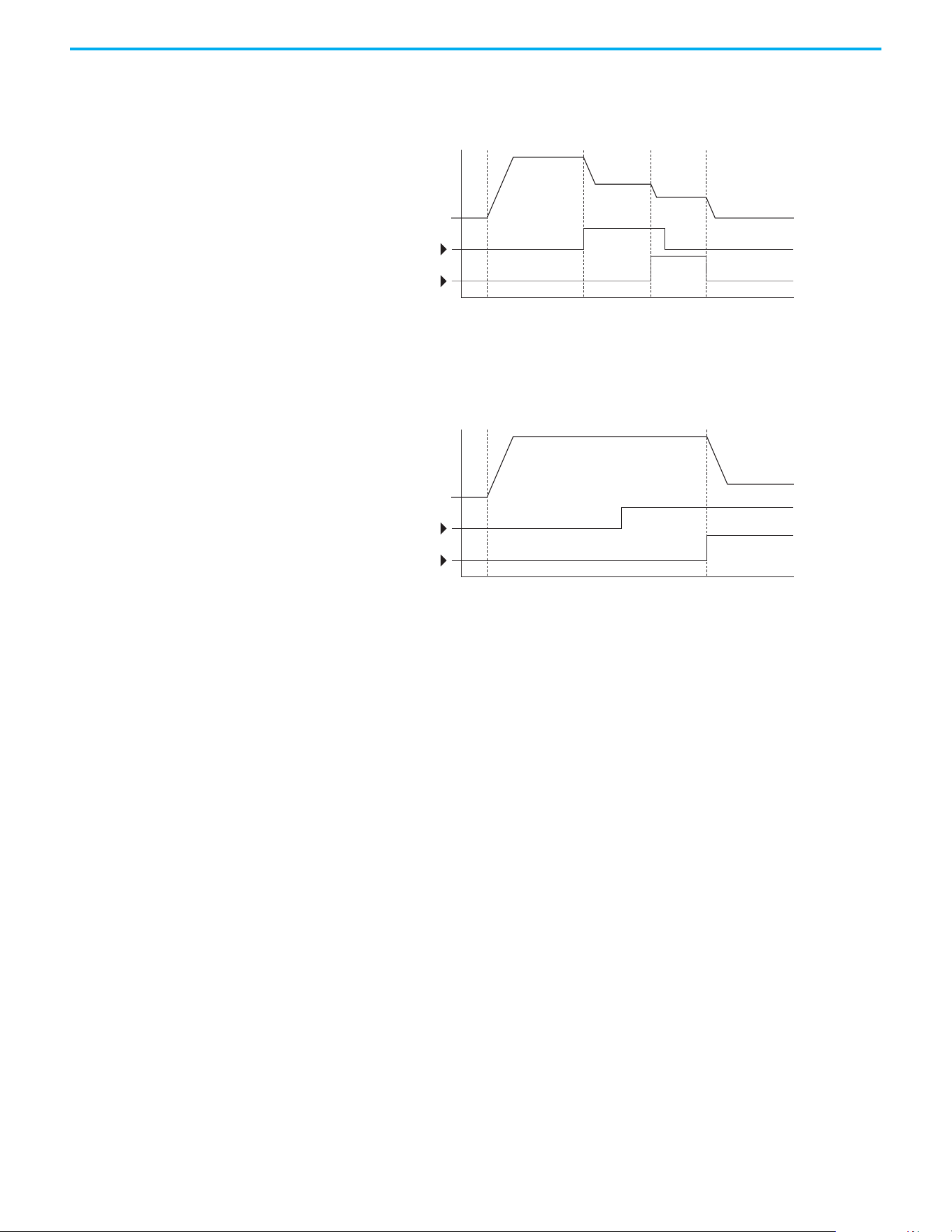
Rockwell Automation Publication 520-UM001N-EN-E - July 2024 215
Appendix D Velocity StepLogic, Basic Logic, and Timer/Counter Functions
• Transition to Step 3 when Logic In 2 returns to a false or off state.
Inputs are not required to remain in the “on” condition except under the
logic conditions that are used for the transition from Step 2 to Step 3.
The step time value and the basic logic may be used together to satisfy machine
conditions. For instance, the step may need to run for a minimum time period
and then use the basic logic to trigger a transition to the next step.
Timer Function Digital inputs and outputs control the timer function and are configured with
parameters t062…t063, t065…t068 [DigIn TermBlk xx] set to 19 “Timer Start”
and 21 “Reset Timer”.
Digital outputs (relay and opto type) define a preset level and indicate when
the level is reached. Level parameters t077 [Relay Out1 Level], t082[Relay Out2
Level], t070 [Opto Out1 Level] and t073 [Opto Out2 Level] are used to set the
desired time in seconds.
Parameters t076 [Relay Out1 Sel], t081 [Relay Out2 Sel], t069 [Opto Out1 Sel]
and t072 [Opto Out2 Sel] are set to 25 “Timer Out” and causes the output to
change state when the preset level is reached.
Example
• Drive starts up and accelerates to 30 Hz.
• After 30 Hz has been maintained for 20 seconds, a 4…20 mA analog input
becomes the reference signal for speed control.
• The timer function is used to select a preset speed with a 20 second
runtime that overrides the speed reference while the digital input is
active.
• Parameters are set to the following options:
- P047 [Speed Reference1] = 6 “4-20mA Input”
- P049 [Speed Reference2] = 7 “Preset Freq”
- t062 [DigIn TermBlk 02] = 1 “Speed Ref 2”
Time
Logic In 1
Logic In 2
Frequency
Start Step 0 Step 1 Step 2 Step 3
Time
Logic In 1
Logic In 2
Frequency
Start Step 0 Step 1

216 Rockwell Automation Publication 520-UM001N-EN-E - July 2024
Appendix D Velocity StepLogic, Basic Logic, and Timer/Counter Functions
- t063 [DigIn TermBlk 03] = 19 “Timer Start”
- t076 [Relay Out1 Sel] = 25 “Timer Out”
- t077 [Relay Out1 Level] = 20.0 seconds
- A411 [Preset Freq 1] = 30.0 Hz
• The control terminal block is wired such that a start command also
triggers the timer start.
• The relay output is wired to I/O Terminal 02 (DigIn TermBlk 02) so that it
forces the input on when the timer starts.
• After the timer is complete, the output is turned off releasing the preset
speed command. The drive defaults to following the analog input
reference as programmed.
Note that a “Reset Timer” input is not required for this example since the
“Timer Start” input both clears and starts the timer.
Counter Function Digital inputs and outputs control the counter function and are configured
with parameters t062…t063, t065…t068 [DigIn TermBlk xx] set to 20 “Counter
In” and 22 “Reset Countr”.
Digital outputs (relay and opto type) define a preset level and indicate when
the level is reached. Level parameters t077 [Relay Out1 Level], t082[Relay Out2
Level], t070 [Opto Out1 Level] and t073 [Opto Out2 Level] are used to set the
desired count value.
Parameters t076 [Relay Out1 Sel], t081 [Relay Out2 Sel], t069 [Opto Out1 Sel]
and t072 [Opto Out2 Sel] are set to 26 “Counter Out” which causes the output to
change state when the level is reached.
Example
• A photo eye is used to count packages on a conveyor line.
• An accumulator holds the packages until 5 are collected.
• A diverter arm redirects the group of five packages to a bundling area.
• The diverter arm returns to its original position and triggers a limit
switch that resets the counter.
• Parameters are set to the following options:
- t065 [DigIn TermBlk 05] = 20 “Counter In”
- t066 [DigIn TermBlk 06] = 22 “Reset Countr”
- t076 [Relay Out1 Sel] = 26 “Counter Out”
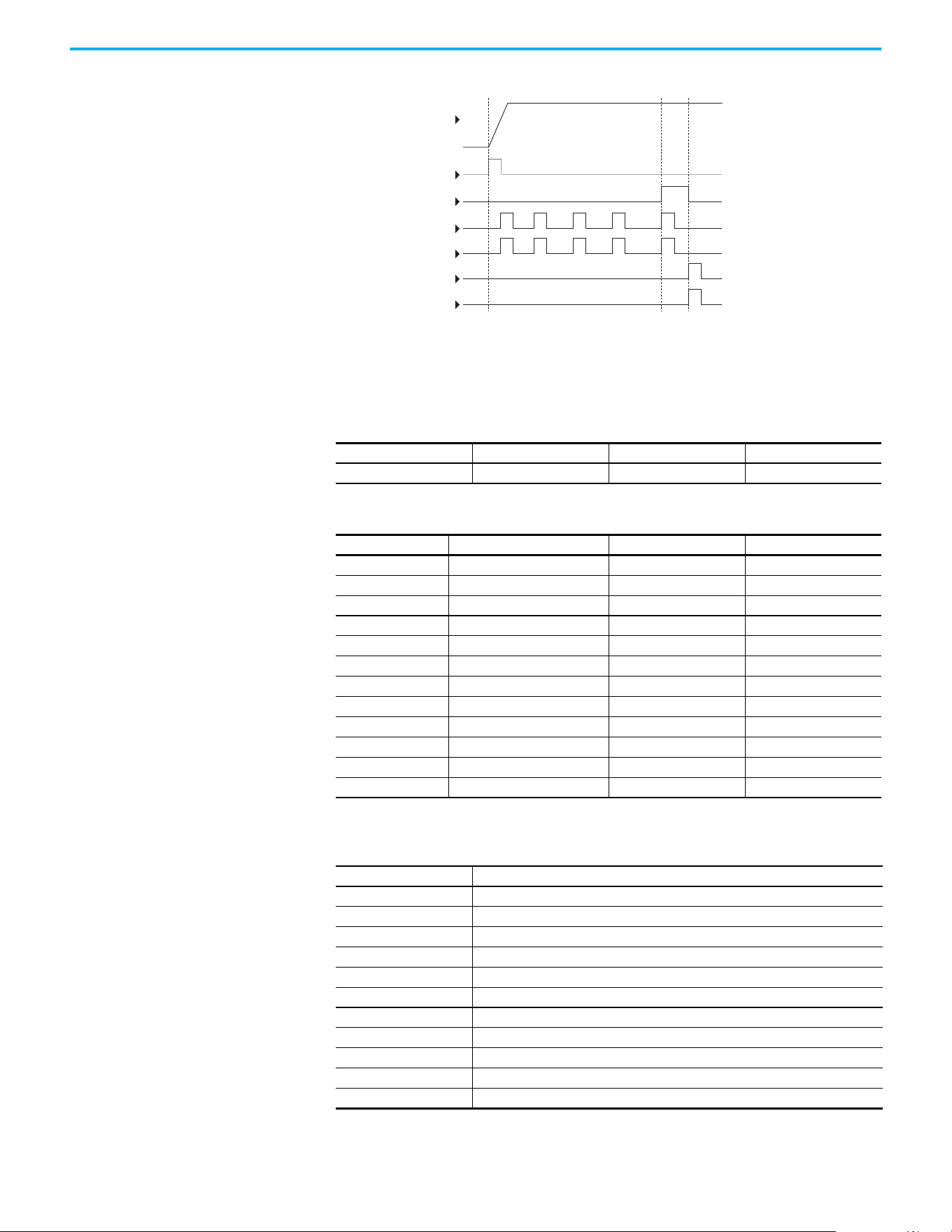
Rockwell Automation Publication 520-UM001N-EN-E - July 2024 217
Appendix D Velocity StepLogic, Basic Logic, and Timer/Counter Functions
- t077 [Relay Out1 Level] = 5.0 Counts
Velocity StepLogic
Parameters
DigIn TermBlk 06
Reset Counter
Limit Switch
DigIn TermBlk 05
Counter In
Photo Eye
Start
Output
Frequency
Relay Out
Code Descriptions for Parameters L180…L187
Digit 4 Digit 3 Digit 2 Digit 1
00F1
Digit 4 – Defines the action during the step currently executing
Setting Accel/Decel Parameter Used StepLogic Output State Commanded Direction
01 Off FWD
11 Off REV
2 1 Off No Output
31 On FWD
41 On REV
5 1 On No Output
62 Off FWD
72 Off REV
8 2 Off No Output
92 On FWD
A2 On REV
b 2 On No Output
Digit 3 – Defines what step to jump to or how to end program when the logic conditions
specified in Digit 2 are met
Setting Logic
0 Jump to Step 0
1 Jump to Step 1
2 Jump to Step 2
3 Jump to Step 3
4 Jump to Step 4
5 Jump to Step 5
6 Jump to Step 6
7 Jump to Step 7
8 End Program (Normal Stop)
9 End Program (Coast to Stop)
A End Program and Fault (F002)

218 Rockwell Automation Publication 520-UM001N-EN-E - July 2024
Appendix D Velocity StepLogic, Basic Logic, and Timer/Counter Functions
Digit 2 – Defines what logic must be met to jump to a step other than the
very next step
Setting Description Logic
0 Skip Step (jump immediately) SKIP
1 Step based on the time programmed in the respective [Stp Logic Time x] parameter. TIMED
2 Step if “Logic In 1” is active (logically true) TRUE
3 Step if “Logic In 2” is active (logically true) TRUE
4 Step if “Logic In 1” is not active (logically false) FALSE
5 Step if “Logic In 2” is not active (logically false) FALSE
6 Step if either “Logic In 1” or “Logic In 2” is active (logically true) OR
7 Step if both “Logic In 1” and “Logic In 2” is active (logically true) AND
8 Step if neither “Logic In 1” or “Logic In 2” is active (logically true) NOR
9 Step if “Logic In 1” is active (logically true) and “Logic In 2” is not active (logically false) XOR
A Step if “Logic In2” is active (logically true) and “Logic In 1” is not active (logically false) XOR
b Step after [Stp Logic Time x] and “Logic In 1” is active (logically true) TIMED AND
C Step after [Stp Logic Time x] and “Logic In 2” is active (logically true) TIMED AND
d Step after [Stp Logic Time x] and “Logic In 1” is not active (logically false) TIMED OR
E Step after [Stp Logic Time x] and “Logic In 2” is not active (logically false) TIMED OR
F Do not step OR no “jump to”, so use Digit 0 logic IGNORE
Digit 1 – Defines what logic must be met to jump to the very next step
Setting Description Logic
0 Skip Step (jump immediately) SKIP
1 Step based on the time programmed in the respective [Stp Logic Time x] parameter. TIMED
2 Step if “Logic In 1” is active (logically true) TRUE
3 Step if “Logic In 2” is active (logically true) TRUE
4 Step if “Logic In 1” is not active (logically false) FALSE
5 Step if “Logic In 2” is not active (logically false) FALSE
6 Step if either “Logic In 1” or “Logic In 2” is active (logically true) OR
7 Step if both “Logic In 1” and “Logic In 2” is active (logically true) AND
8 Step if neither “Logic In 1” or “Logic In 2” is active (logically true) NOR
9 Step if “Logic In 1” is active (logically true) and “Logic In 2” is not active (logically false) XOR
A Step if “Logic In 2” is active (logically true) and “Logic In 1” is not active (logically false) XOR
b Step after [Stp Logic Time x] and “Logic In 1” is active (logically true) TIMED AND
C Step after [Stp Logic Time x] and “Logic In 2” is active (logically true) TIMED AND
d Step after [Stp Logic Time x] and “Logic In 1” is not active (logically false) TIMED OR
E Step after [Stp Logic Time x] and “Logic In 2” is not active (logically false) TIMED OR
F Use logic programmed in Digit 1 IGNORE

Rockwell Automation Publication 520-UM001N-EN-E - July 2024 219
Appendix E
Encoder/Pulse Train Usage and Position
StepLogic Application
Encoder and Pulse Train
Usage
The PowerFlex 520-series drives include a pulse train input that is built into the
terminal block. PowerFlex 525 drives also support an optional encoder card.
The pulse train and encoder can be used for many of the same functions, but
the pulse train supports up to 100 kHz at 24V, and uses the drive built-in
terminal block. The encoder supports up to 250 kHz dual channel at 5V, 12V, or
24V and requires the optional encoder board to be installed. When A535
[Motor
Fdbk Type] is set to a value other than zero, the drive is set to use an encoder or
pulse train. The drive uses the encoder or pulse train in several ways
depending on the settings of other parameters. The drive uses the encoder or
pulse train as shown below (listed in order of priority):
1. If enabled by P047
, P049, or P051 [Speed Referencex], the encoder or
pulse train is used directly as a commanded speed (normally used with a
pulse train) or as a position reference (normally used with a quadrature
encoder).
2. If not enabled by the Speed Reference parameters, the encoder or pulse
train can be used with the PID function if enabled by A459
or A471 [PID x
Ref Sel], or A460 or A472 [PID x Fdback Sel].
3. If not enabled by the Speed Reference or PID function parameters, the
encoder or pulse train can be used with A535
[Motor Fdbk Type] for direct
feedback and trim of the speed command. The normal slip compensation
is not used in this case. Instead the drive uses the encoder or pulse train
to determine actual output frequency and adjust the output frequency to
match the command. Parameters A538
[Ki Speed Loop] and A539 [Kp
Speed Loop] are used in this control loop. The primary benefit of this
mode is increased speed accuracy when compared to open-loop slip
compensation. It does not provide speed bandwidth improvement.
Encoder Interface
The incremental encoder option card can source 5 volt or 12 volt power and
accept 5, 12, or 24 volts single ended or differential inputs. See Appendix B
for
ordering information.
IMPORTANT
The encoder usage, and position StepLogic application that is covered
in this chapter is specific to PowerFlex 525 drives only.
IMPORTANT
Only the 25-ENC-1 Encoder works properly in the PowerFlex 525 drive.
Installing an incorrect encoder card, such as the 25-ENC-2 for
PowerFlex 527 drives causes damage to the PowerFlex 525 drive.
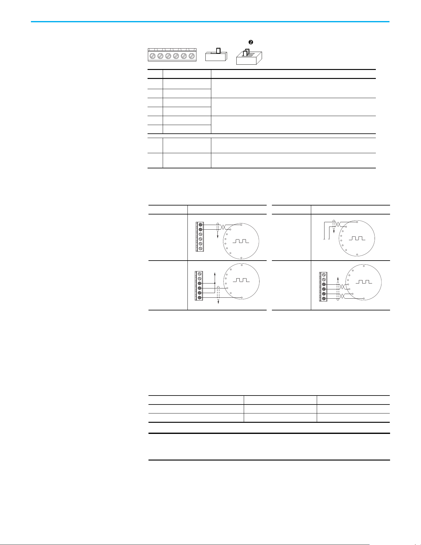
220 Rockwell Automation Publication 520-UM001N-EN-E - July 2024
Appendix E Encoder/Pulse Train Usage and Position StepLogic Application
HTL/TTL DIP Switches
This feature is available on 25-ENC-1 encoder. Set the two switches to HTL
(default) or TTL (On) based on the type of encoder signal that you are using in
your application. You must set all switches to the same position.
+VCmB-BA-A
12V 5V
n
HTL TTL (ON)
No. Signal Description
+V
5…12V Power
(1)(2)
(1) When using 12V Encoder power, 24V I/O power, maximum output current at I/O Terminal 11 is 50 mA.
(2) If Encoder requires 24V power, it must be supplied by an external power source.
Internal power source 250 mA (isolated).
Cm Power Return
B- Encoder B (NOT)
Quadrature B input.
BEncoder B
A- Encoder A (NOT)
Single channel, pulse train, or quadrature A input.
AEncoder A
Output
DIP switch selects 12 volt or 5 volt power that is supplied at terminals “+V” and
“Cm” for the encoder.
HTL/TTL DIP
switches
Set the position of the DIP switches based on the type of encoder signal used.
You must set all switches to the same position.
Encoder Wiring Examples
I/O Connection Example I/O Connection Example
Encoder Power
– Internal Drive
Power
Internal (drive)
12V DC, 250 mA
Encoder Power
– External
Power Source
Encoder Signal
– Single-Ended,
Dual Channel
Encoder Signal
– Differential,
Dual Channel
Compatible Encoder Output Voltage
Switch Position Low Level (UL) High Level (UH)
TTL <1.5V >2.5V
HTL <3.5V >5V
IMPORTANT
Only the 25-ENC-1 Encoder works properly in the PowerFlex 525 drive.
Installing an incorrect encoder card, such as the 25-ENC-2 for
PowerFlex 527 drives causes damage to the PowerFlex 525 drive.
Common
+12V DC
(250 mA)
A
A-
B
B-
Cm
+V
to SHLD
+
Common
External
Power
Supply
to
SHLD
A NOT
A
B
B NOT
to SHLD
to Power Supply
Common
A
A-
B
B-
Cm
+V
to SHLD
A NOT
B
A
B NOT
A
A-
B
B-
Cm
+V

Rockwell Automation Publication 520-UM001N-EN-E - July 2024 221
Appendix E Encoder/Pulse Train Usage and Position StepLogic Application
Wiring Notes The encoder option card can supply 5V or 12V power (250 mA maximum) for an
encoder. Be sure that the DIP switch is set properly for the encoder. In general,
12V provides higher noise immunity.
The encoder can handle 5V, 12V, or 24V inputs, but the pulse train can handle
only 24V inputs. The inputs automatically adjust to the voltage applied and no
additional drive adjustment is necessary. If a single-channel input is used, it
must be wired between the A (signal) and A- (signal common) channels.
Determine Encoder Pulse
Per Revolution (PPR)
Specification Based on
Speed Resolution
Use the following formula to determine the encoder pulse per revolution (PPR)
specification based on the speed resolution.
Example 1
To determine the PPR for quadrature encoder, to achieve 0.06 Hz of speed
resolution on a 4-pole motor (2-pole pair) with a base speed of 60 Hz:
Therefore, select 8333 PPR or higher for the quadrature encoder to achieve the
desired speed resolution of 0.06 Hz.
Example 2
To determine the speed resolution, using a 1024 PPR quadrature incremental
encoder on a 4-pole (2-pole pair) motor:
IMPORTANT
A quadrature encoder provides rotor speed and direction. Therefore,
the encoder must be wired such that the forward direction matches the
motor forward direction. If the drive is reading encoder speed but the
position regulator or other encoder function is not working properly,
remove power to the drive, then do one of the following:
• Swap the A and A (NOT) encoder channels.
• Swap the B and B (NOT) encoder channels.
• Swap any two motor leads.
Drives will fault when an encoder is incorrectly wired and A535
[Motor
Fdbk Type] is set to 5 “Quad Check”.
The operating speed range depends on the motor control mode
selected (SVC or VVC). For more information, see Performance with
Encoder on page 170.
Speed resolution (Hz) =
1
encoder pulse number x 4
10
-3
sec
x pole pairs
0.06 Hz =
= ~8333 pulse
1
encoder pulse number x 4
10
-3
sec
x 2
Speed resolution (Hz) =
1
1024 x 4
10
-3
sec
x 2
= 0.49 Hz

222 Rockwell Automation Publication 520-UM001N-EN-E - July 2024
Appendix E Encoder/Pulse Train Usage and Position StepLogic Application
Therefore, using a 1024 PPR quadrature encoder gives a speed resolution of
0.49 Hz.
Positioning Overview The PowerFlex 525 drive includes a simple position regulator, which can be
used without the need for multiple limit switches or photo-eyes. This position
regulator can be used as a standalone controller for simple applications (up to
eight positions) or in conjunction with a controller for more flexibility.
This position regulator is not intended to replace high-end servo controllers or
any application that needs high bandwidth or very high torque at low speeds.
Common Guidelines for All
Applications
The position regulator can be configured for operation appropriate for a
variety of applications. Certain parameters need to be adjusted in all cases.
P047
[Speed Reference1] must be set to 16 “Positioning”.
A535
[Motor Fdbk Type] must be set to the match the feedback device.
Positioning mode must use A535
[Motor Fdbk Type] option 4.
A535
[Motor Fdbk Type] Options
0 “None” indicates that no encoder is used. This cannot be used for
positioning.
1 “Pulse Train” is a single channel input, no direction, speed feedback
only. This should not be used for positioning. The Single Channel
selection is similar to a Pulse Train, but uses the standard encoder
scaling parameters.
2 “Single Chan” is a single channel input, no direction, speed feedback
only. This should not be used for positioning. Single channel uses the
standard encoder scaling parameters.
3 “Single Check” is a single channel input with encoder signal loss
detection. The drive faults if it detects that the input pulses do not
match the expected motor speed. This should not be used for
positioning.
4 “Quadrature” is a dual channel encoder input with direction and
speed from the encoder. This may be used for positioning control.
5 “Quad Check” is a dual channel encoder with encoder signal loss
detection. The drive faults if it detects that the encoder speed does not
match the expected motor speed.
A544
[Reverse Disable] should be set to 0 “Rev Enabled” to allow bidirectional
movement necessary for position control.
P039
[Torque Perf Mode] default setting is 1 “SVC”. However, any mode can be
used to improve the low speed torque for positioning applications. For best

Rockwell Automation Publication 520-UM001N-EN-E - July 2024 223
Appendix E Encoder/Pulse Train Usage and Position StepLogic Application
results, tune the application first. The autotune routine can be completed to
further improve the drive-motor performance.
A550
[Bus Reg Enable] default setting is 1 “Enabled”. If the deceleration time is
too short, the drive may overshoot the desired position. For best results, a
longer deceleration time may be necessary. A550
[Bus Reg Enable] can be
disabled to provide precise stopping movements, but the deceleration time
must be manually tuned so that it is long enough to avoid F005 “OverVoltage”
faults.
A437
[DB Resistor Sel] default setting is 0 “Disabled”. If improved deceleration
performance is required a Dynamic Brake resistor can be used. If used, this
parameter should be set to the appropriate setting for the resistor selected.
P035
[Motor NP Poles] must be set to match the number of motor poles on the
motor driven by the PowerFlex 520-series drive.
A536
[Encoder PPR] must be set to match the number of pulses per revolution
of the encoder used (that is, 1024 PPR Encoder).
A559
[Counts Per Unit] sets the number of encoder counts that will be used to
define one position unit. This allows the encoder positions to be defined in
terms of units important to the application. For example, if 1 cm of travel on a
conveyor belt requires 0.75 turns of the motor, the motor encoder is 1024 PPR,
and the Motor Feedback type is set to Quadrature, then this parameter would
need to be set to (4 x 1024 x 0.75) = 3072 counts for 1 cm of travel. Then all other
positions could be set up in units of “cm”.
A564
[Encoder Pos Tol] indicates the desired position tolerance for the system.
This determines how close the drive must be to the commanded position
before the drive indicates “At Home” or “At Position” in units of raw encoder
pulses. This has no effect on the actual positioning control of the motor.
Positioning Operation Parameter A558 [Positioning Mode] must be set to properly match the desired
operation of the positioning function.
A558
[Positioning Mode] Options
0 “Time Steps” uses StepLogic times. This mode ignores the StepLogic
settings and moves through the steps (Step 0 to Step 7 and back to Step
0) based on the times programmed into L190
…L197 [Stp Logic Time x].
This can be used when the desired position is based only on time. In
addition, this mode only accepts absolute positions in a positive
direction from “home”. This option provides an easy way to implement
a simple positioning program or to test the basic positioning setup.
For additional flexibility one of the other settings should be used.
1 “Preset Input” directly commands movement to any step based on
the status of the digital inputs programmed for “Preset Freq”. This
setting ignores the StepLogic Commands settings and instead the
drive moves directly to whatever step is currently commanded by
A410
…A425 [Preset Freq x] and L200…L214 [Step Units x]. This is useful

224 Rockwell Automation Publication 520-UM001N-EN-E - July 2024
Appendix E Encoder/Pulse Train Usage and Position StepLogic Application
when an application needs direct access to any position step based on
discrete inputs. This mode moves in the forward direction from Home
and is an absolute move.
2 “StepLogic” provides a highly flexible mode of operation. This can be
used to move through the steps (Step 0 to Step 7 and back to Step 0) or
can jump to a different step at any time based on time or the status of
digital inputs or communication commands. In this mode, the drive
always starts at Step 0 of the StepLogic profile.
3 “Preset StpL” is identical to 2 “StepLogic” except the drive uses the
current status of the Preset Inputs to determine which StepLogic step
to begin. This only affects the initial step. After start, the drive will
move through the steps in the same manner as if setting 2 was
selected.
4 “StpLogic-Lst” is identical to 2 “StepLogic” except the drive uses the
step prior to its last stop command to determine which StepLogic step
to begin. This only affects the initial step. After start, the drive will
move through the steps in the same manner as if setting 2 was
selected. This allows a process to be stopped and then restarted at the
position where it stopped.
In all position modes, the following parameters control the characteristics at
each step:
L200
, L202, L204, L206, L208, L210, L212 and L214 [Step Units x] are the
number value to the left of the decimal (whole number) of the eight positions
desired for an application, beginning with Step 0 (L200) and continuing with
each step until Step 7 (L214). For example, enter 2 into this parameter if you
would like a commanded position of 2.77.
L201, L203, L205, L207, L209, L211, L213, and L215 [Step Units F x] are the
number value to the right of the decimal (the portion less than 1) of the eight
positions desired for an application, beginning with Step 0 (L201) and
continuing with each step until Step 7 (L215). For example, enter 0.77 into this
parameter if you would like a commanded position of 2.77.
A410
…A417 [Preset Freq x] are the parameters that define the maximum
frequency that the drive runs at during the corresponding step. For example, if
IMPORTANT
Advanced StepLogic options such as incremental move are not
available in this mode.
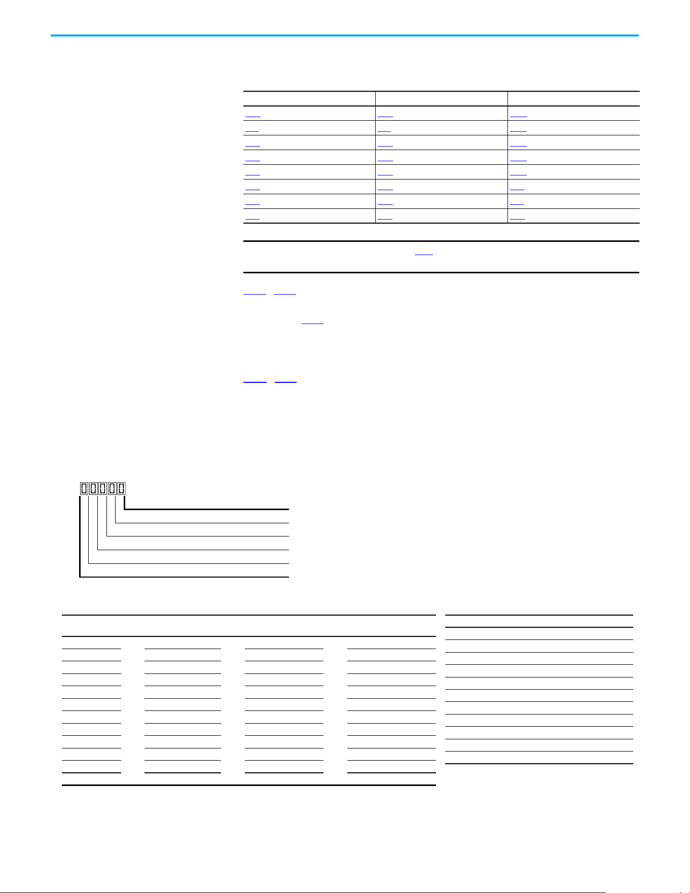
Rockwell Automation Publication 520-UM001N-EN-E - July 2024 225
Appendix E Encoder/Pulse Train Usage and Position StepLogic Application
[Preset Freq 2] is set to 40 Hz, the drive accelerates to 40 Hz maximum when
moving to Position 2.
L190
…L197 [Stp Logic Time x] are the parameters that define the time that the
drive remains in each corresponding step if that step is time-based. For
example, if L192
[Stp Logic Time 2] is set to 5.0 seconds and that step is time-
based, the drive remains in Step 2 for 5.0 seconds. Note that this is the total
time that is needed to accelerate, run, and decelerate to that position.
L180
…L187 [Stp Logic x] are the parameters that allow additional flexibility and
control various aspects of each step when a positioning mode is selected that
utilizes the StepLogic functions. In Positioning mode these parameters have a
different function than when used for normal velocity StepLogic. Each of the
four digits controls one aspect of the position step. The following is a listing of
the available settings for each digit:
Frequency Source Step Source Position Source
A410 [Preset Freq 0] L180 [Stp Logic 0] L200 [Step Units 0]
A411
[Preset Freq 1] L181 [Stp Logic 1] L202 [Step Units 1]
A412
[Preset Freq 2] L182 [Stp Logic 2] L204 [Step Units 2]
A413 [Preset Freq 3] L183 [Stp Logic 3] L206 [Step Units 3]
A414
[Preset Freq 4] L184 [Stp Logic 4] L208 [Step Units 4]
A415
[Preset Freq 5] L185 [Stp Logic 5] L210 [Step Units 5]
A416
[Preset Freq 6] L186 [Stp Logic 6] L212 [Step Units 6]
A417 [Preset Freq 7] L187 [Stp Logic 7] L214 [Step Units 7]
IMPORTANT
The default value for A410 [Preset Freq 0] is 0.00 Hz. This value must be
changed or the drive will not be able to move during Step 0.
Logic for next step Digit 1
Logic to jump to a different step Digit 2
Different step to jump Digit 3
Step settings Digit 4
Not Used
Velocity Control Settings (Digit 4)
Required
Setting
Accel/Decel
Param. Used
StepLogic
Output State
Commanded
Direction
0 Accel/Decel 1 Off FWD
1 Accel/Decel 1 Off REV
2 Accel/Decel 1 Off No Output
3 Accel/Decel 1 On FWD
4 Accel/Decel 1 On REV
5 Accel/Decel 1 On No Output
6 Accel/Decel 2 Off FWD
7 Accel/Decel 2 Off REV
8 Accel/Decel 2 Off No Output
9 Accel/Decel 2 On FWD
A Accel/Decel 2 On REV
b Accel/Decel 2 On No Output
Settings (Digit 3)
Setting Description
0Jump to Step 0
1Jump to Step 1
2Jump to Step 2
3Jump to Step 3
4Jump to Step 4
5Jump to Step 5
6Jump to Step 6
7Jump to Step 7
8 End Program (Normal Stop)
9 End Program (Coast to Stop)
A End Program and Fault (F2)

226 Rockwell Automation Publication 520-UM001N-EN-E - July 2024
Appendix E Encoder/Pulse Train Usage and Position StepLogic Application
Incremental move commands cause the drive to move the amount specified
based on the current position. Absolute commands are always with reference
to “Home”.
A565
[Pos Reg Filter] provides a low pass filter at the input of the position
regulator.
A566
[Pos Reg Gain] is a single adjustment for increasing or decreasing the
responsiveness of the position regulator. For faster response, the filter should
be reduced and/or the gain should be increased. For smoother response with
less overshoot, the filter should be increased and/or the gain should be
reduced. In general, the gain has a larger effect on most systems than the filter.
Homing Routine This drive supports incremental encoders only. Therefore, when the drive
powers up it resets the current position to zero. If this is known to be, correct
the position routine can be started without further adjustment. However, in
most applications the drive will need to be “homed” after each power-up and
prior to starting the position routine.
This can be accomplished in one of the following two ways:
1. Manual Homing–Program the following drive parameters:
t062
, t063, t065...t068 [DigIn TermBlk xx] = 37 “Pos Redefine”
Program one of the digital inputs to 37 “Pos Redefine”. Then, move the
system into the home position with a run command, a jog command,
or by manually moving the system into the home position. Then,
toggle the “Pos Redefine” input. This sets the drive to “Home” at its
current position and d388
[Units Traveled H] and d389 [Units Traveled
Positioning Settings (Digit 4)
Required
Setting
Accel/Decel
Param. Used
StepLogic
Output State
Direction
From Home
Type of
Command
0 Accel/Decel 1 Off FWD Absolute
1 Accel/Decel 1 Off FWD Incremental
2 Accel/Decel 1 Off REV Absolute
3 Accel/Decel 1 Off REV Incremental
4 Accel/Decel 1 On FWD Absolute
5 Accel/Decel 1 On FWD Incremental
6 Accel/Decel 1 On REV Absolute
7 Accel/Decel 1 On REV Incremental
8 Accel/Decel 2 Off FWD Absolute
9 Accel/Decel 2 Off FWD Incremental
A Accel/Decel 2 Off REV Absolute
b Accel/Decel 2 Off REV Incremental
C Accel/Decel 2 On FWD Absolute
d Accel/Decel 2 On FWD Incremental
E Accel/Decel 2 On REV Absolute
F Accel/Decel 2 On REV Incremental
Settings (Digit 2 and 1)
Setting Description
0 Skip Step (Jump Immediately)
1 Step Based on [Stp Logic Time x]
2 Step if “Logic In 1” is Active
3 Step if “Logic In 2” is Active
4 Step if “Logic In 1” is Not Active
5 Step if “Logic In 2” is Not Active
6 Step if either “Logic In 1” or “Logic In 2” is Active
7 Step if both “Logic In 1” and “Logic In 2” are Active
8 Step if neither “Logic In 1” nor “Logic In 2” is Active
9
Step if “Logic In 1” is Active and “Logic In 2” is Not
Active
A
Step if “Logic In 2” is Active and “Logic In 1” is Not
Active
b
Step after [Stp Logic Time x] and “Logic In 1” is
Active
C
Step after [Stp Logic Time x] and “Logic In 2” is
Active
d
Step after [Stp Logic Time x] and “Logic In 1” is Not
Active
E
Step after [Stp Logic Time x] and “Logic In 2” is
Not Active
F Do Not Step/Ignore Digit 2 Settings
Use the Wizard in Connected Components Workbench software to
simplify setup instead of manually configuring the parameters.

Rockwell Automation Publication 520-UM001N-EN-E - July 2024 227
Appendix E Encoder/Pulse Train Usage and Position StepLogic Application
L] are set to zero. Alternately, the “Pos Redefine” bit in A560 [Enh
Control Word] can be toggled instead of utilizing a digital input.
2. Automatic Homing to Limit Switch–Program the following drive
parameters:
t062
, t063, t065…t068 [DigIn TermBlk xx] = 35 “Find Home”
Program one of the digital inputs to 35 “Find Home”.
t062
, t063, t065…t068 [DigIn TermBlk xx] = 34 “Home Limit”
Program one of the digital inputs to 34 “Home Limit”. Normally, the
“Home Limit” input would be wired to a proximity switch or photo-eye
and indicate that the system is in the home position.
A562
[Find Home Freq] sets the frequency that the drive uses while it is
moving to the home position during the automatic homing routine.
A563
[Find Home Dir] sets the direction that the drive uses while it is
moving to the home position during the automatic homing routine.
To begin the automatic homing routine, activate the “Find Home” input and
then initiate a valid start command. The drive then ramps to the speed set in
A562
[Find Home Freq] and in the direction set in A563 [Find Home Dir] until
the digital input defined as “Home Limit” is activated. If the drive passes this
point too quickly it then reverses direction at 1/10th A562
[Find Home Freq] to
the point where the Home Limit switch reactivates. Approximately 1 second
after the routine finds home the drive stops. Alternately, the “Find Home Freq”
and/or “Home Limit” bits in A560
[Enh Control Word] can be activated instead
of utilizing a digital input. The inputs or bits should be returned to inactive
after the routine is complete.
Encoder and Position
Feedback
d376 [Speed Feedback] indicates the measured speed feedback or the
calculated speed feedback when no feedback device is selected. Parameter d376
[Speed Feedback] is the number value to the left of the decimal (whole number)
and d377
[Speed Feedback F] is the value to the right of the decimal (the portion
less than 1).
d378
[Encoder Speed] indicates the measured speed of the feedback device.
This is useful if the encoder is not used for motor speed control. However, the
encoder must be used for some purpose in order for d378 [Encoder Speed] to
indicate a value. Parameter d378 [Encoder Speed] is the number value to the
left of the decimal (whole number) and d379
[Encoder Speed F] is the number
to the right of the decimal (the portion less than 1).
IMPORTANT
The “Pos Redefine” input or bit must be returned to inactive before
starting the position routine. Otherwise the drive continuously
reads a position of “0” (home) and the position routine does not
function correctly.
IMPORTANT
After the position is reached the drive stops. If the Find Home is
removed before the homing is complete, the drive begins running the
position routine without the proper home. In this case Home is not reset
and the position is in relation to the power-up position.

228 Rockwell Automation Publication 520-UM001N-EN-E - July 2024
Appendix E Encoder/Pulse Train Usage and Position StepLogic Application
d388, d389 [Units Traveled x] indicate the current position of the system in
terms of units away from Home. Parameter d388 [Units Traveled H] is the
number value to the left of the decimal (whole number) and d389 [Units
Traveled L] is the number to the right of the decimal (the portion less than 1).
d387
[Position Status] indicates the status of the positioning functions. The
indication bits are:
Bit 0 “Dir Positive” indicates the current direction that the drive has
moved from Home.
Bit 1 “At Position” indicates whether the drive is at its commanded
position. If the drive is within A564
[Encoder Pos Tol] of the
commanded position, this bit will be active.
Bit 2 “At Home” indicates whether the drive is at Home. If the drive is
within A564
[Encoder Pos Tol] of “Home”, this bit will be active.
Bit 3 “Drive Homed” indicates whether the drive has been homed
since power-up. This bit will be active once the drive has been homed
either manually or automatically. It will remain active until the next
power down.
Use Over Communications If eight steps are not adequate for the application or if dynamic program
changes are required, many of the positioning functions can be controlled
through an active communication network. The following parameters allow
this control.
C121
[Comm Write Mode]
Repeated writes to parameters over a communication network can cause
damage to the drive EEPROM. This parameter allows the drive to accept
parameter changes without writing to the EEPROM.
C122
[Cmd Stat Select]
Selects velocity-specific or position/fibers-specific Command and Status Word
bit definitions for use over a communication network.
A560
[Enh Control Word]
This parameter allows many of the positioning functions to be completed
through parameter control using an explicit message. This allows the
operation over communications instead of with hardware inputs. The bits
have the same functions as the digital input options of the same name. Options
relating to positioning are:
Bit 0 “Home Limit” indicates that the drive is at the home position.
Bit 1 “Find Home” causes the drive to find home at the next start
command. Deactivate this bit after completing the homing routine.
IMPORTANT
Parameter values set prior to setting 1 “RAM only” are saved in RAM.

Rockwell Automation Publication 520-UM001N-EN-E - July 2024 229
Appendix E Encoder/Pulse Train Usage and Position StepLogic Application
Bit 2 “Hold Step” overrides other inputs and causes the drive to remain
at its current step (running at zero speed once it reaches its position)
until released.
Bit 3 “Pos Redefine” resets the home position to the current position
of the machine. Deactivate this bit after completing the homing
routine.
Bit 4 “Sync Enable” holds the existing frequency when A571 [Sync
Time] is set to enable speed synchronization. When this bit is
deactivated the drive accelerates to the new commanded frequency
based on A571 [Sync Time].
Bit 5 “Traverse Dis” disables the traverse function when this bit is
active.
Bit 6 “Logic In 1” provides an identical function and is logically ORed
with setting 24 “Logic In 1” for t062
, t063, t065…t068 [DigIn TermBlk
xx]. It can be used to move through the StepLogic functions (speed or
position) using comms control without requiring actual digital input
transitions.
Bit 7 “Logic In 2” provides an identical function and is logically ORed
with setting 25 “Logic In 2” for t062
, t063, t065…t068 [DigIn TermBlk
xx]. It can be used to move through the StepLogic functions (speed or
position) using comms control without requiring actual digital input
transitions.
L200
…L214 [Step Units x]
All position steps can be written to while the drive is running. The changes
takes place at the next move. For example, if step 0 is overwritten while the
drive is moving to step 0, the drive moves to the previous command position at
step 0. The next time that the drive is commanded to return to step 0 it
proceeds to the new position. One possible use of this capability is when an
application requires full control of the movement by a controller external to
the drive. The StepLogic program might be written to jump from step 0 back to
step 0 when Input 1 is active. The controller could write any desired position to
step 0 and then toggle the input 1 bit of A560
[Enh Control Word] to cause the
drive to move to the new position. This allows almost unlimited flexibility and
can be used with absolute or incremental moves.
Setup Notes The RA computer tool (Connected Components Workbench software) can
make setup of the positioning functions much easier. See the latest versions
for additional tools or wizards, which can aid in the setup.

230 Rockwell Automation Publication 520-UM001N-EN-E - July 2024
Appendix E Encoder/Pulse Train Usage and Position StepLogic Application
Notes:
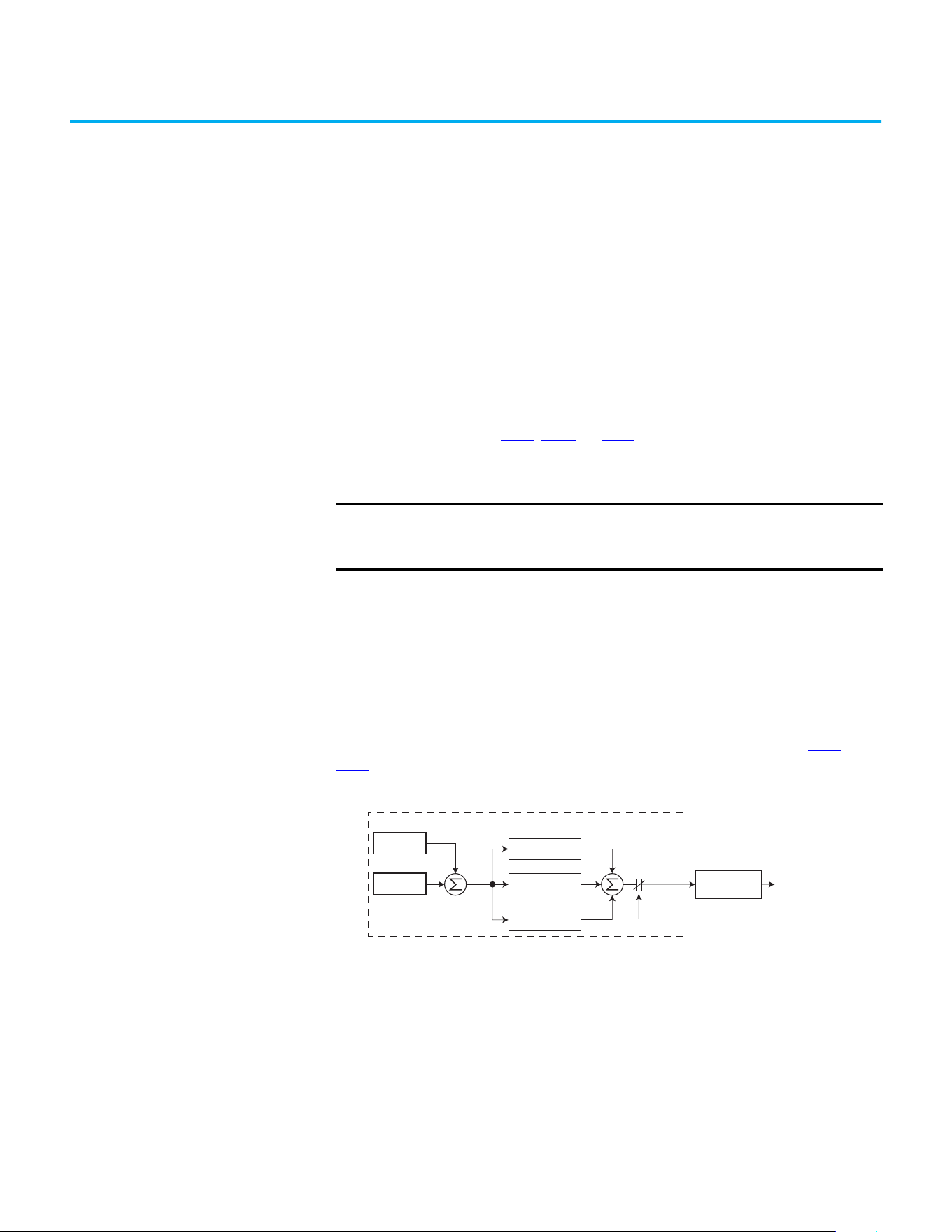
Rockwell Automation Publication 520-UM001N-EN-E - July 2024 231
Appendix F
PID Set Up
PID Loop The PowerFlex 520-series drive features built-in PID (proportional, integral,
derivative) control loops. The PID loop is used to maintain a process feedback
(such as pressure, flow, or tension) at a desired setpoint. The PID loop works
by subtracting the PID feedback from a reference and generating an error
value. The PID loop reacts to the error, based on the PID Gains, and outputs a
frequency to try to reduce the error value to 0.
To enable the PID loop, P047
, P049, or P051 [Speed Referencex] must be set to
11 “PID1 Output” or 12 “PID2 Output”, and the corresponding speed reference
activated.
Exclusive Control and Trim Control are two basic configurations where the
PID loop may be used.
Exclusive Control
In Exclusive Control, the Speed Reference becomes 0, and the PID Output
becomes the entire Freq Command. Exclusive Control is used when A458
or
A470
[PID x Trim Sel] is set to option 0. This configuration does not require a
master reference, only a desired setpoint, such as a flow rate for a pump.
Example
• In a pumping application, the PID Reference equals the Desired System
Pressure setpoint.
• The Pressure Transducer signal provides PID Feedback to the drive.
Fluctuations in actual system pressure, due to changes in flow, result in a
PID Error value.
• The drive output frequency increases or decreases to vary motor shaft
speed to correct for the PID Error value.
• The Desired System Pressure setpoint is maintained as valves in the
system are opened and closed causing changes in flow.
IMPORTANT
PowerFlex 523 has one PID control loop.
PowerFlex 525 has two PID control loops, of which only one can be in
use at any time.
–
+
PID Prop Gain
PID Loop
PID Integ Time
PID Di Rate
PID Selected
PID Fdbk
PID Ref
PID
Error
+
+
+
PID
Output
Accel/Decel
Ramp
Freq
Command
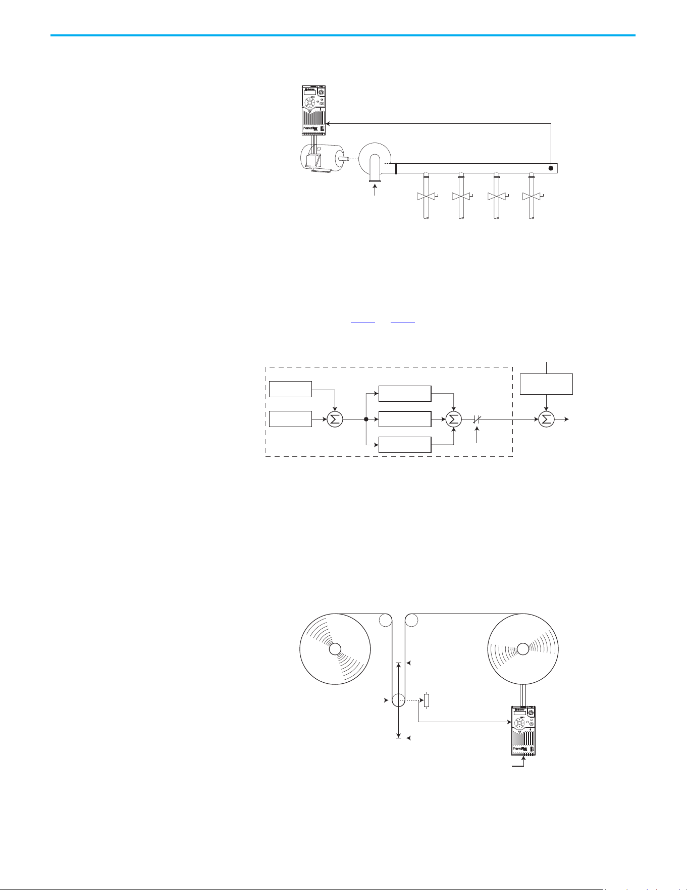
232 Rockwell Automation Publication 520-UM001N-EN-E - July 2024
Appendix F PID Set Up
• When the PID Control Loop is disabled, the Commanded Speed is the
Ramped Speed Reference.
Trim Control
In Trim Control, the PID Output is added to the Speed Reference. In Trim
mode, the output of the PID loop bypasses the accel/decel ramp as shown. Trim
Control is used when A458
or A470 [PID x Trim Sel] is set to any option other
than 0.
Example
• In a winder application, the PID Reference equals the Equilibrium
setpoint.
• The Dancer Pot signal provides PID Feedback to the drive. Fluctuations
in tension result in a PID Error value.
• The Master Speed Reference sets the wind/unwind speed.
• As tension increases or decreases during winding, the Speed Reference is
trimmed to compensate. Tension is maintained near the Equilibrium
setpoint.
Pump
PID Feedback =
Pressure Transducer Signal
PID Reference =
Desired System Pressure
Esc
Sel
–
+
PID Prop Gain
PID Loop
PID Integ Time
PID Di Rate
PID Selected
[Speed Referencex]
PID Fdbk
PID Ref
PID
Error
+
+
+
+
PID
Output
Output
Freq
+
Accel/Decel
Ramp
[Speed Referencex]
0V
PID Feedback =
Dancer Pot Signal
10V
PID Reference =
Equilibrium Set Point
Esc
Sel
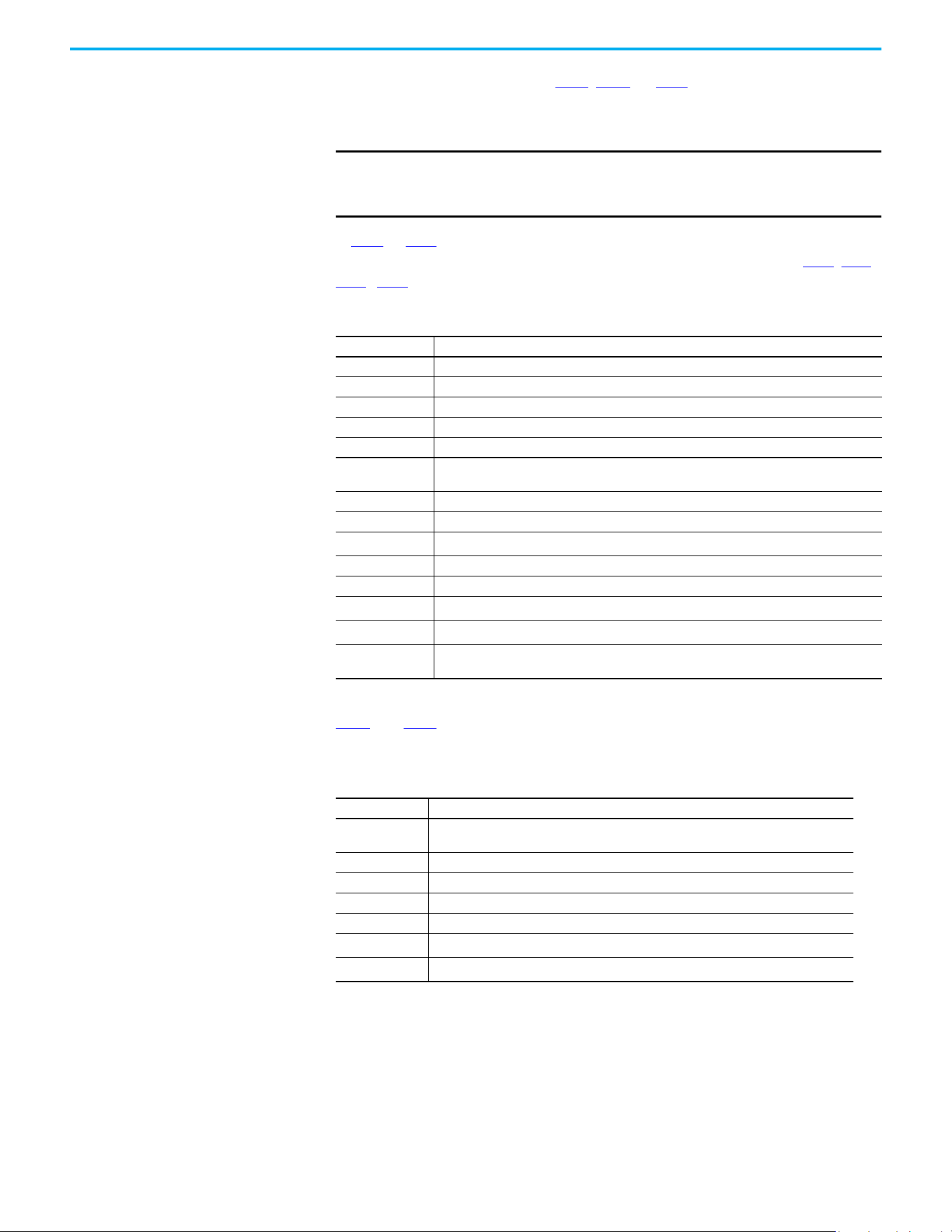
Rockwell Automation Publication 520-UM001N-EN-E - July 2024 233
Appendix F PID Set Up
PID Reference and
Feedback
PID mode is enabled by setting P047, P049, or P051 [Speed Referencex] to
11 “PID1 Output” or 12 “PID2 Output”, and activating the corresponding speed
reference.
If A459
or A471 [PID x Ref Sel] is not set to 0 “PID Setpoint”, PID can still be
disabled by select programmable digital input options (parameters t062
, t063,
t065
…t068 [DigIn TermBlk xx]) such as “Purge”.
A460
and A472 [PID x Fdback Sel] are used to select the source of the PID
feedback.
IMPORTANT
PowerFlex 523 has one PID control loop.
PowerFlex 525 has two PID control loops, of which only one can be in
use at any time.
A459, A471 [PID x Ref Sel] Options
Options Description
0 “PID Setpoint“ A464 or A476 [PID x Setpoint] is used to set the value of the PID Reference.
1 “Drive Pot” The drive potentiometer is used to set the value of the PID Reference.
2 “Keypad Freq” The drive keypad is used to set the value of the PID Reference.
2 ”Serial/DSI” The reference word from the Serial/DSI communication network becomes the PID Reference.
4 “Network Opt” The reference word from a communication network option becomes the PID Reference.
5“0-10V Input”
Selects the 0…10V Input. The PID does not function with a bipolar analog input. It ignores any
negative voltages and treats them like a zero.
6 “4-20mA Input” Selects the 4…20 mA Input.
7 “Preset Freq” A410…A425 [Preset Freq x] is used as an input for the PID Reference.
8 “AnlgIn Multi”
(1)
(1) Setting is specific to PowerFlex 525 drives only.
The product of the 0…10V and 4…20mA Inputs is used as an input for the PID Reference.
9 “MOP Freq” A427 [MOP Freq] is used as an input for the PID Reference.
10”Pulse Input” Pulse train is used as an input for the PID Reference.
11 “Step Logic”
(1)
StepLogic is used as an input for the PID Reference.
12“Encoder”
(1)
Encoder is used as an input for the PID Reference.
13“EtherNet/IP”
(1)
The reference word from the EtherNet/IP communication network becomes the PID
Reference.
A460, A472 [PID x Fdback Sel] Options
Options Description
0“0-10V Input”
Selects the 0…10V Input (default setting). The PID will not function with a bipolar analog
input. It ignores any negative voltages and treat them like a zero.
1 “4-20mA Input“ Selects the 4…20 mA Input.
2 “Serial/DSI” Serial/DSI will be used as an input for the PID Feedback.
3 “Network Opt” The reference word from a communication network option becomes the PID Reference.
4 “Pulse Input” Pulse train will be used as an input for the PID Feedback.
5“Encoder”
(1)
(1) Setting is specific to PowerFlex 525 drives only.
Encoder will be used as an input for the PID Feedback.
6“EtherNet/IP”
(1)
EtherNet/IP will be used as an input for the PID Feedback.

234 Rockwell Automation Publication 520-UM001N-EN-E - July 2024
Appendix F PID Set Up
Analog PID Reference
Signals
Parameters t091 [Anlg In 0-10V Lo] and t092 [Anlg In 0-10V Hi] are used to
scale or invert an analog PID Reference or PID Feedback.
Scale Function
For a 0…5V signal, the following parameter settings are used so that a 0V signal
= 0% PID Reference and a 5V signal = 100% PID Reference.
• t091 [Anlg In 0-10V Lo] = 0.0%
• t092 [Anlg In 0-10V Hi] = 50.0%
• A459 [PID 1 Ref Sel] = 5 “0-10V Input”
Invert Function
For a 4…20 mA signal, the following parameter settings are used so that a 20
mA signal = 0% PID Reference and a 4 mA signal = 100% PID Reference.
• t095 [Anlg In4-20mA Lo] = 100.0%
• t096 [Anlg In4-20mA Hi] = 0.0%
• A459 [PID 1 Ref Sel] = 6 “4-20mA Input”
PID Deadband
Parameters A465 and A477 [PID x Deadband] are used to set a range, in
percent, of the PID Reference that the drive ignores.
Example
• A465 [PID 1 Deadband] = 5.0%
•The PID Reference is 25.0%
• The PID Regulator does not act on a PID Error that falls between 20.0%
and 30.0%
0 10 20 30 40 50 60 70 80 90 100
PID Reference (%)
Input Volts
2
4
6
8
10
12
0102030405060708090100
PID Reference (%)
4-20 mA Input
4
8
12
16
20
24
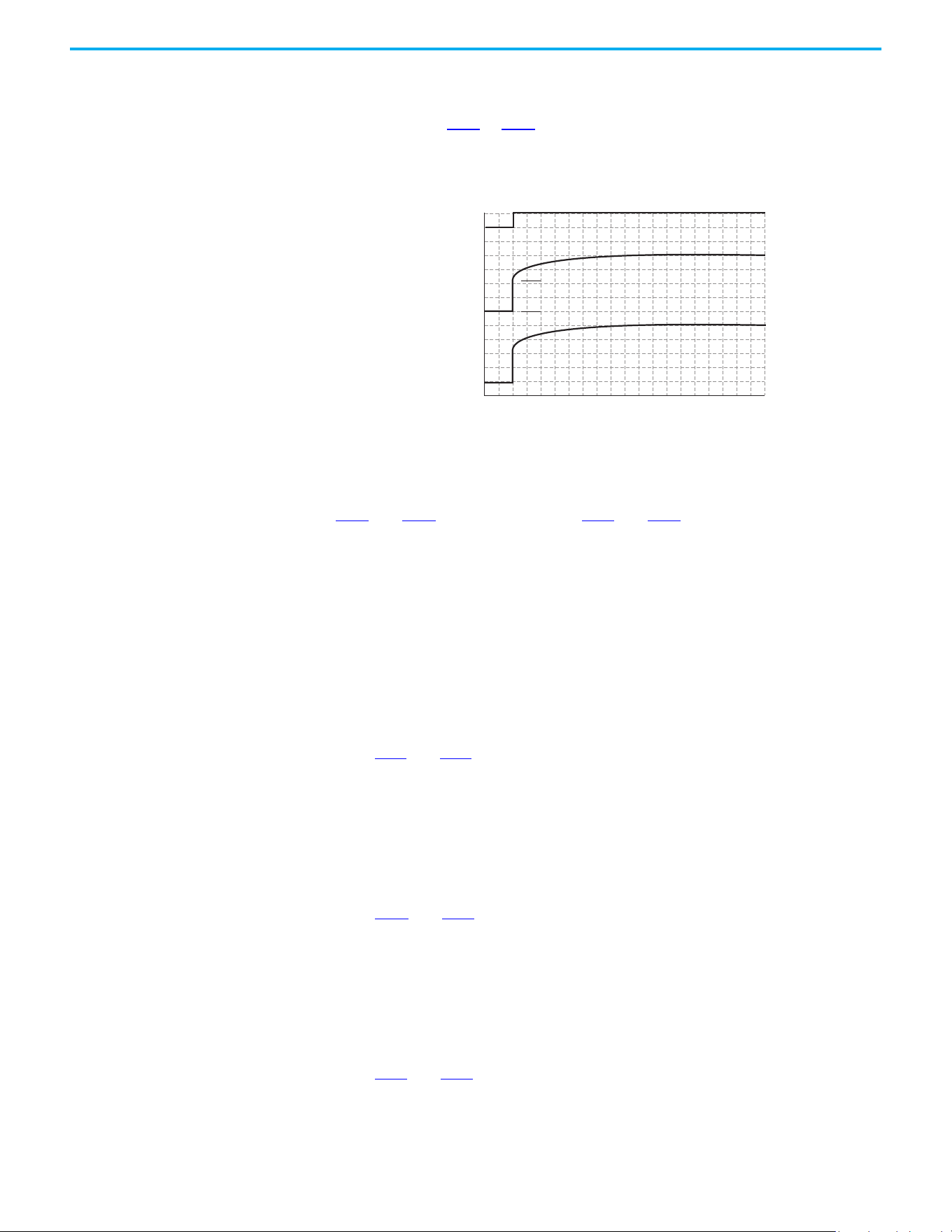
Rockwell Automation Publication 520-UM001N-EN-E - July 2024 235
Appendix F PID Set Up
PID Preload
The value set in A466 or A478 [PID x Preload], in Hz, is pre-loaded into the
integral component of the PID at any start or enable. This causes the drive’s
frequency command to initially jump to that preload frequency, and the PID
loop starts regulating from there.
PID Limits
A456 and A468 [PID x Trim Hi] and A457 and A469 [PID x Trim Lo] are used to
limit the PID output and are only used in trim mode. [PID x Trim Hi] sets the
maximum frequency for the PID output in trim mode. [PID x Trim Lo] sets the
reverse frequency limit for the PID output in trim mode. Note that when the
PID reaches the Hi or Lo limit, the PID regulator stops integrating so that
windup does not occur.
PID Gains
The proportional, integral, and differential gains make up the PID regulator.
• A461
and A473 [PID x Prop Gain]
The proportional gain (unitless) affects how the regulator reacts to the
magnitude of the error. The proportional component of the PID
regulator outputs a speed command proportional to the PID error. For
example, a proportional gain of 1 would output 100% of max frequency
when the PID error is 100% of the analog input range. A larger value for
[PID x Prop Gain] makes the proportional component more responsive,
and a smaller value makes it less responsive. Setting [PID x Prop Gain] to
0.00 disables the proportional component of the PID loop.
• A462
and A474 [PID x Integ Time]
The integral gain (units of seconds) affects how the regulator reacts to
error over time and is used to get rid of steady state error. For example,
with an integral gain of 2 seconds, the output of the integral gain
component would integrate up to 100% of max frequency when the PID
error is 100% for 2 seconds. A larger value for [PID x Integ Time] makes
the integral component less responsive, and a smaller value makes it
more responsive. Setting [PID x Integ Time] to 0.0 disables the integral
component of the PID loop.
• A463
and A475 [PID x Diff Rate]
The Differential gain (units of 1/seconds) affects the rate of change of the
PID output. The differential gain is multiplied by the difference between
the previous error and current error. Thus, with a large error the D has a
large effect and with a small error the D has less of an effect. This
PID Enabled
Freq Cmd
PID Output
PID Pre-load Value
PID Pre-load Value > 0

236 Rockwell Automation Publication 520-UM001N-EN-E - July 2024
Appendix F PID Set Up
parameter is scaled so that when it is set to 1.00, the process response is
0.1% of P044
[Maximum Freq] when the process error is changing at 1% /
second. A larger value for [PID x Diff Rate] makes the differential term
have more of an effect and a small value makes it have less of an effect. In
many applications, the D gain is not needed. Setting [PID x Diff Rate] to
0.00 (factory default) disables the differential component of the PID
loop.
Guidelines for Adjusting the PID Gains
1. Adjust the proportional gain. During this step it may be desirable to
disable the integral gain and differential gain by setting them to 0. After
a step change in the PID Feedback:
- If the response is too slow increase A461 or A473 [PID x Prop Gain].
- If the response is too quick and/or unstable (see Unstable Response on
page 236), decrease A461 or A473 [PID x Prop Gain].
- Typically, A461 or A473 [PID x Prop Gain] is set to some value below the
point where the PID begins to go unstable.
2. Adjust the integral gain (leave the proportional gain set as in Step 1).
After a step change in the PID Feedback:
- If the response is too slow (see Slow Response – Over Damped on
page 236), or the PID Feedback does not become equal to the PID
Reference, decrease A462 or A474 [PID x Integ Time].
- If there is a lot of oscillation in the PID Feedback before settling out
(see Oscillation – Under Damped on page 237
), increase A462 or A474
[PID x Integ Time].
3. At this point, the differential gain may not be needed. However, if after
determining the values for A461 or A473 [PID x Prop Gain] and A462 or
A474 [PID x Integ Time]:
- Response is still slow after a step change, increase A463 or A475 [PID x
Diff Rate].
- Response is still unstable, decrease A463 or A475 [PID x Diff Rate].
The following figures show some typical responses of the PID loop at different
points during adjustment of the PID Gains.
Unstable Response
Slow Response – Over Damped
PID Feedback
PID Reference
Time
PID Feedback
PID Reference
Time

Rockwell Automation Publication 520-UM001N-EN-E - July 2024 237
Appendix F PID Set Up
Oscillation – Under Damped
Good Response – Critically Damped
PID Feedback
PID Reference
Time
PID Feedback
PID Reference
Time

238 Rockwell Automation Publication 520-UM001N-EN-E - July 2024
Appendix F PID Set Up
Notes:

Rockwell Automation Publication 520-UM001N-EN-E - July 2024 239
Appendix G
Safe Torque Off Function
The PowerFlex 525 Safe Torque Off (STO) function, when used with other
safety components, helps provide protection according to EN ISO 13849 and
EN62061 for Safe Torque Off and protection against restart. The PowerFlex 525
Safe Torque Off function is just one component in a safety control system.
Components in the system must be chosen and applied appropriately to
achieve the desired level of operator safeguarding.
PowerFlex 525 Safe Torque
Off Overview
The PowerFlex 525 Safe Torque Off function:
• Provides the Safe Torque Off function that is defined in EN 61800-5-2.
• Blocks gate-firing signals from reaching the insulated gate bipolar
transistor (IGBT) output devices of the drive. This helps prevent the
IGBTs from switching in the sequence necessary to generate torque in
the motor.
• Can be used in combination with other safety devices to fulfill the
requirements of a system “Safe Torque Off” function that satisfies
Category 3 / PLd according to EN ISO 13849-1 and SIL CL2 according to
EN 62061, IEC 61508, and EN 61800-5-2.
EC Type Examination
Certification
TÜV Rheinland has certified the PowerFlex 525 Safe Torque Off function
compliant with the requirements for machines that are defined in Annex I of
the EC Directive 2006/42/EC, and that it complies with the requirements of the
relevant standards that are listed as follows:
IMPORTANT
The Safe Torque Off function that is covered in this chapter is specific
to PowerFlex 525 drives only.
IMPORTANT
The function is suitable for performing mechanical work on the drive
system or affected area of a machine only. It does not provide electrical
safety.
ATTENTION: Electric Shock Hazard. Verify that all sources of AC and DC
power are de-energized and locked out or tagged out in accordance with the
requirements of ANSI/NFPA 70E, Part II.
To avoid an electric shock hazard, verify that the voltage on the bus
capacitors has discharged before performing any work on the drive.
Measure the DC bus voltage at the +DC and -DC terminals or test points
(refer to your drive’s User Manual for locations). The voltage must be zero.
In STO mode, hazardous voltages may still be present at the motor. To avoid
an electric shock hazard, disconnect power to the motor and verify that the
voltage is zero before performing any work on the motor.

240 Rockwell Automation Publication 520-UM001N-EN-E - July 2024
Appendix G Safe Torque Off Function
• EN ISO 13849-1 Safety of machinery – Safety related parts of control
systems – Part 1: General principles for design.
(PowerFlex 525 STO achieves Category 3 / PLd
• EN 61800-5-2 Adjustable speed electrical power drive systems – Part 5-2
Safety requirements – Functional.
(PowerFlex 525 STO achieves SIL CL 2)
• EN 62061 Safety of machinery – Functional safety of safety-related
electrical, electronic, and programmable electronic control systems.
• IEC 61508 Part 1-7 Functional safety of electrical/electronic/
programmable electronic safety-related systems – Parts 1-7.
TÜV also certifies that the PowerFlex 525 STO can be used in applications up to
Category 3/ PLd according to EN ISO 13849-1 and SIL 2 according to EN 62061 /
EN 61800-5-2 / IEC 61508.
The TÜV Rheinland certificate can be found at rok.auto/certifications
.
UK Type Examination
Certification
TÜV Rheinland has certified the PowerFlex 525 Safe Torque Off function
compliant with the requirements for machines that are defined in 2008 No.
1597 Supply of Machinery (Safety) Regulations (MD), and that it complies with
the requirements of the relevant standards that are listed as follows:
• EN ISO 13849-1 Safety of machinery – Safety related parts of control
systems – Part 1: General principles for design.
(PowerFlex 525 STO achieves Category 3 / PLd
• EN 61800-5-2 Adjustable speed electrical power drive systems – Part 5-2
Safety requirements – Functional.
(PowerFlex 525 STO achieves SIL CL 2)
• EN 62061 Safety of machinery – Functional safety of safety-related
electrical, electronic, and programmable electronic control systems.
• IEC 61508 Part 1-7 Functional safety of electrical/electronic/
programmable electronic safety-related systems – Parts 1-7.
TÜV also certifies that the PowerFlex 525 STO can be used in applications up to
Category 3/ PLd according to EN ISO 13849-1 and SIL 2 according to EN 62061 /
EN 61800-5-2 / IEC 61508.
The TÜV Rheinland certificate can be found at rok.auto/certifications
.
EMC Instructions The PowerFlex 525 Safe Torque Off function requires CE and UK Conformity
as described on page 52
.
Using PowerFlex 525 Safe
Torque Off
The PowerFlex 525 Safe Torque Off function is intended to be part of the
safety-related control system of a machine. Before use, a risk assessment
should be performed that compares the PowerFlex 525 Safe Torque Off
function specifications and all foreseeable operational and environmental
characteristics of the machine to which it is to be fitted.

Rockwell Automation Publication 520-UM001N-EN-E - July 2024 241
Appendix G Safe Torque Off Function
A safety analysis of the machine section that is controlled by the drive is
required to determine how often the safety function should be tested for
proper operation during the life of the machine.
Safety Concept The PowerFlex 525 Safe Torque Off function is suitable for use in safety
applications up to and including Category 3 / PLd according to EN ISO 13849-1
and SIL 2 according to EN 62061 / EN 61800-5-2 / IEC 61508.
In addition, the PowerFlex 525 STO can be used together with other
components in a safety application to achieve an overall Category 3 / PLe
according to EN ISO 13849-1 and SIL 3 according to EN 62061 and IEC 61508.
This is illustrated in Example 3 in this appendix.
Safety requirements are based on the standards current at the time of
certification.
The PowerFlex 525 Safe Torque Off function is intended for use in safety-
related applications where the de-energized state is considered to be the safe
state. All examples in this manual are based on achieving de-energization as
the safe state for typical Machine Safety and Emergency Shutdown (ESD)
systems.
Important Safety Considerations
The system user is responsible for:
• The set-up, safety rating, and validation of any sensors or actuators
connected to the system
• Completing a system-level risk assessment and reassessing the system
any time a change is made
• Certification of the system to the desired safety performance level
• Project management and proof testing
• Programming the application software and the safety option
configurations in accordance with the information in this manual
• Access control to the system, including access code handling
ATTENTION: The following information is merely a guide for proper
installation. Rockwell Automation cannot assume responsibility for the
compliance or the noncompliance to any code, national, local or otherwise
for the proper installation of this equipment. A hazard of personal injury
and/or equipment damage exists if codes are ignored during installation.
ATTENTION: In STO mode, hazardous voltages may still be present at the
motor. To avoid an electric shock hazard, disconnect power to the motor
and verify that the voltage is zero before performing any work on the motor.
ATTENTION: In the event of the failure of two output IGBTs in the drive,
when the PowerFlex 525 Safe Torque Off has controlled the drive outputs to
the off state, the drive may provide energy for up to 180 ° of rotation in a 2-
pole motor before torque production in the motor ceases.

242 Rockwell Automation Publication 520-UM001N-EN-E - July 2024
Appendix G Safe Torque Off Function
• Analyzing all configuration settings and choosing the proper setting to
achieve the required safety rating
Functional Proof Test
The PFD and PFH values that are provided in the table below are contingent
upon the Proof Test Interval (PTI). Before the end of the PTI specified in the
table below, a proof test of the STO safety function must be performed in order
for the specified PFD and PFH values to remain valid.
PFD and PFH Data
PFD and PFH calculations are based on the equations from Part 6 of EN 61508.
This table provides data for a 20-year proof test interval and demonstrates the
worst-case effect of various configuration changes on the data.
Safety Reaction Time
The safety reaction time is the amount of time from a safety-related event as
input to the system until the system is in the Safe State.
The safety reaction time from an input signal condition that triggers a safe
stop, to the initiation of Safe Torque Off, is 100 ms (maximum).
IMPORTANT
When applying Functional Safety, restrict access to qualified, authorized
personnel who are trained and experienced.
ATTENTION: When designing your system, consider how personnel will exit
the machine if the door locks while they are in the machine. Additional
safeguarding devices may be required for your specific application.
PFD and PFH for 20-year Proof Test Interval
Attribute Value
PFD 6.62E-05 (MTTF = 3593 years)
PFH
D
8.13E-10
SFF 83%
DC 62.5%
CAT 3
HFT 1 (1oo2)
PTI 20 YEARS
Hardware Type Type A
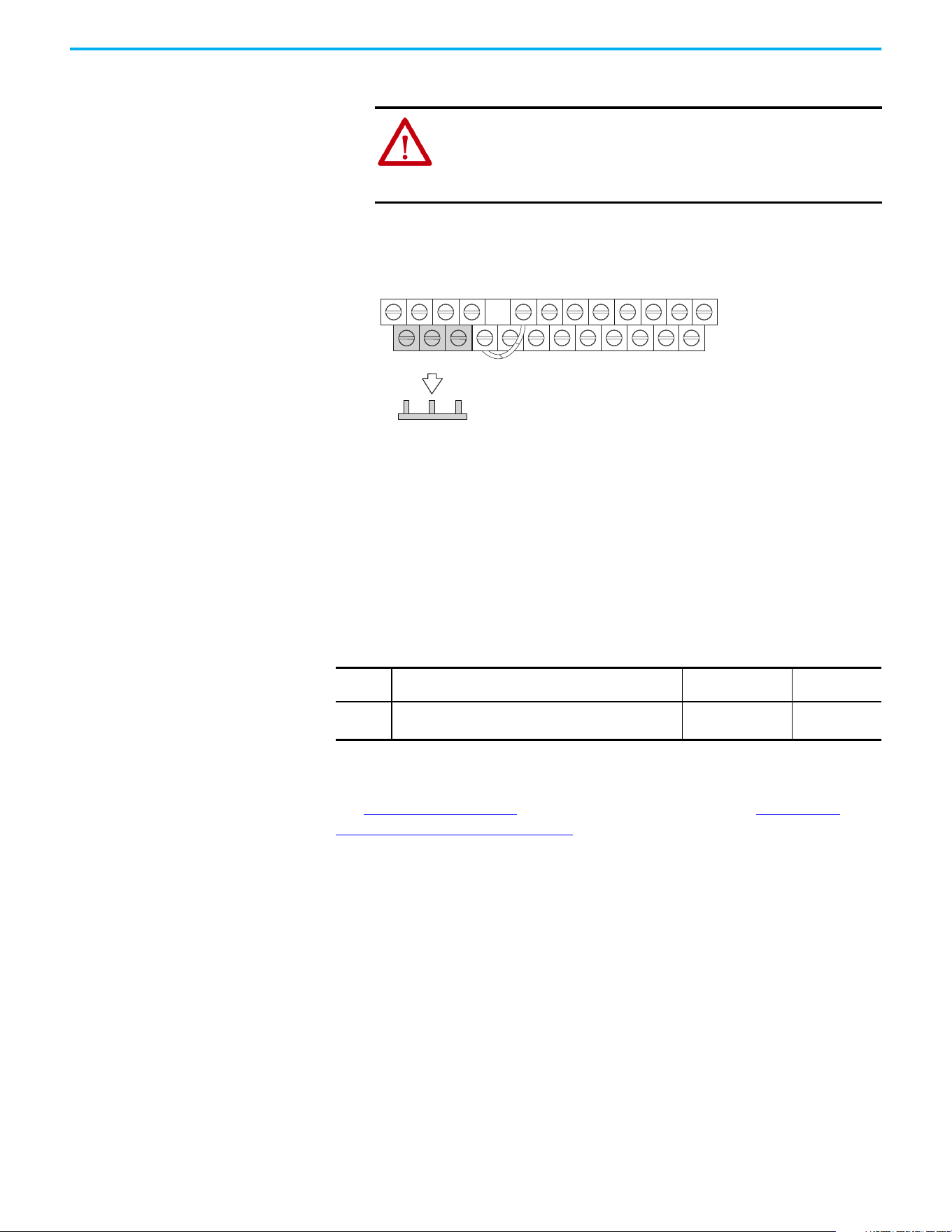
Rockwell Automation Publication 520-UM001N-EN-E - July 2024 243
Appendix G Safe Torque Off Function
Enabling PowerFlex 525
Safe Torque Off
1. Remove all power to the drive.
2. Loosen the screw of terminals Safety 1, Safety 2, and Safety +24V
(S1, S2, S+) on the control I/O terminal block.
3. Remove the protective jumper.
4. The Safe Torque Off function is now enabled and the terminals are ready
to function as safety inputs.
Wiring Important points to remember about wiring:
• Always use copper wire.
• Wire with an insulation rating of 600V or greater is recommended.
• Control wires should be separated from power wires by at least
0.3 m (1 ft).
See I/O Wiring on page 37
for wiring recommendations and Control I/O
Terminal Designations on page 43 for terminal descriptions.
If Safety Inputs S1 and S2 are powered by an external +24V source, apply it only
in an SELV system, PELV system, or low voltage Class 2 circuit.
PowerFlex 525 Safe Torque
Off Operation
The PowerFlex 525 Safe Torque Off function disables the drive’s output IGBTs
by breaking the link with the drive microcontroller. When used in combination
with a safety input device, the system satisfies the requirements of EN ISO
13849 and EN62061 for Safe Torque Off and helps protect against restart.
Under normal drive operation, both safety inputs (Safety 1 and Safety 2) are
energized, and the drive is able to run. If either input is de-energized, the gate
control circuit becomes disabled. To meet EN ISO 13849 operation, both safety
ATTENTION: To avoid an electric shock hazard, verify that the
voltage on the bus capacitors has discharged before performing any
work on the drive. Measure the DC bus voltage at the +DC and -DC
terminals or test points (refer to your drive’s user manual for the
location of the terminals). The voltage must be zero.
R1
S1 S2 S+ 11 12 13 14 15 16 17 18 19
R2 R5 R6 01 02 03 04 05 06 07 08
Recommended Wire
Type
Wire Type
(1)
(1) Recommendations are for 50 °C (122 °F) ambient temperature.
75 °C (167 °F) wire must be used for 60 °C (140 °F) ambient temperature.
90 °C (194 °F) wire must be used for 70 °C (158 °F) ambient temperature.
Description
Min Insulation
Rating
Shielded
Multi-conductor shielded cable such as Belden 8770 (or
equiv.)
0.750 mm
2
(18 AWG),
3 conductor, shielded
300V, 60 °C
(140 °F)

244 Rockwell Automation Publication 520-UM001N-EN-E - July 2024
Appendix G Safe Torque Off Function
channels must be de-energized. See the following examples for more
information.
Verify Operation Test the safety function for proper operation after the initial setup of the
PowerFlex 525 Safe Torque Off function. Retest the safety function at the
intervals that are determined by the safety analysis that is described on
page 240
.
Verify that both safety channels are functioning according to the following
table.
Discrepancy Time of the Safety Inputs
For example, if S1 is disabled and S2 did not follow after the discrepancy time,
fault F111 “Safety Hardware” will occur. However, if S1 is disable and S2 follows
before the discrepancy time, fault F059 “Safety Open” occurs.
The discrepancy time is one second for PowerFlex 525 FRN 5.xxx and later. The
discrepancy time is 10 milliseconds for PowerFlex 525 FRN 4.xxx and earlier.
IMPORTANT
By itself, the Safe Torque Off function initiates a coast-to-stop action.
Additional protective measures must be applied when an application
requires a change to the stop action.
Channel Operation and Verification
Safety Function
Status
Drive In
Safe State
Drive In
Safe State
Drive In
Safe State
Drive
Able To Run
Drive Status
Configured by t105
[Safety Open En]
Fault F111
(Safety Hardware)
Fault F111
(Safety Hardware)
Ready/Run
Safety Channel Operation
Safety Input S1 No Power Applied Power Applied No Power Applied Power Applied
Safety Input S2 No Power Applied No Power Applied Power Applied Power Applied
IMPORTANT
If an external fault is present on the wiring or circuitry controlling the
Safety 1 or Safety 2 inputs for a period of time, the Safe Torque Off
function may not detect this condition. When the external fault
condition is removed the Safe Torque Off function allows an enable
condition. Fault in the external wiring shall either be detected by
external logic, or excluded (wiring must be protected by cable ducting or
armoring), according to EN ISO 13849-2.
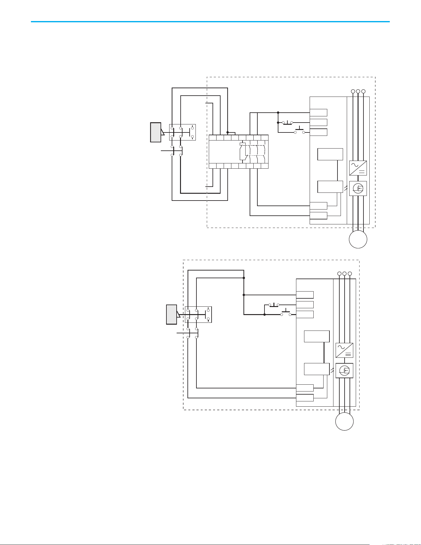
Rockwell Automation Publication 520-UM001N-EN-E - July 2024 245
Appendix G Safe Torque Off Function
Connection Examples Example 1 – Safe Torque Off Connection with Coast-to-Stop Action,
SIL 2/PLd
Stop Category 0 – Coast
(1) An enclosure is recommended. External wiring failure modes must be considered as described in EN ISO 13849-2. Use an
enclosure or other measure to exclude these failure modes.
(2) In some situations, a safety relay is not required if both the switch and PowerFlex 525 are installed in the same enclosure.
Stop
Start
A1
S21 S11 S52 41 13 23 33
A2
24V DC
common
+24V DC
S22 S14 S34 42 14 24 34
MSR
GuardMaster
Trojan
Gate
E-Stop
latching
button
+24V DC
PF 525
Stop
Start
Gate control
power supply
Gate control
circuit
AC line
input power
S1
S2
M
(1)
Stop
Start
GuardMaster
Trojan
Gate
E-Stop
latching
button
+24V DC
PF 525
Stop
Start
Gate control
power supply
Gate control
circuit
AC line
input power
S1
S2
M
(2)
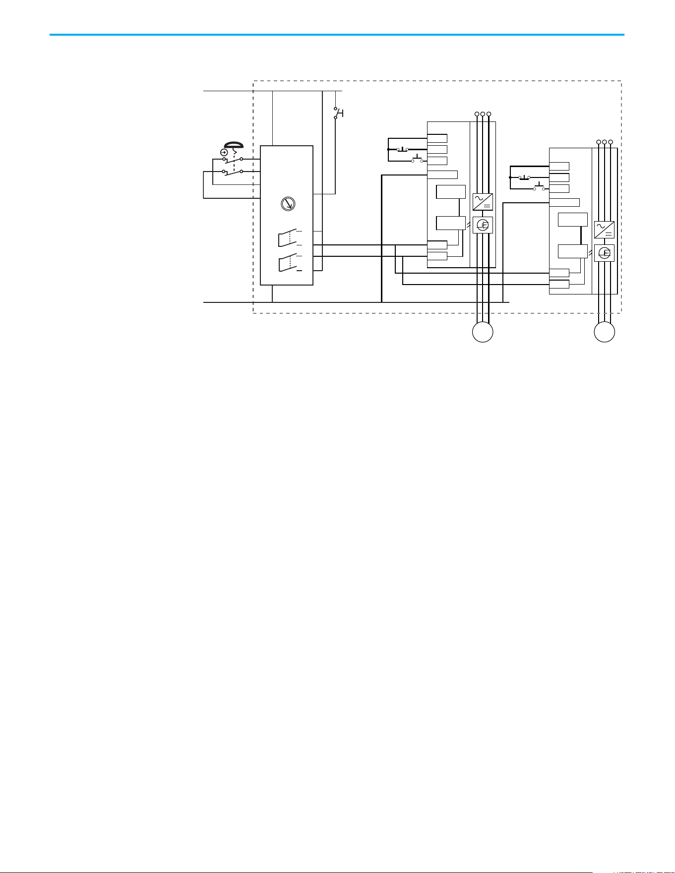
246 Rockwell Automation Publication 520-UM001N-EN-E - July 2024
Appendix G Safe Torque Off Function
Stop Category 0 – Coast with Two PowerFlex 525 Drives
(1) An enclosure is recommended. External wiring failure modes must be considered as described in EN ISO 13849-2. Use an
enclosure or other measure to exclude these failure modes.
(2) Each safety input draws 6 mA from the supply.
Circuit Status
The circuit is shown with the guard door closed and the system ready for
normal drive operation.
Operating Principle
This is a dual-channel system with monitoring of the Safe Torque Off circuit
and drive. Opening the guard door switches the input circuits (S13-S14 & S21-
S22) to the Minotaur™ monitoring safety relay unit. The output circuits (13-14 &
23-24) will cause the Safe Torque Off Enable circuit to trip and the motor will
coast-to-stop. To restart the drive, the Minotaur safety relay must first be reset
followed by a valid start command to the drive.
Fault Detection
A fault that is detected on the Minotaur safety input circuits will result in the
lockout of the system at the next operation and will not cause loss of the safety
function.
A fault that is detected on the PowerFlex 525 safety enable redundant inputs
will result in the lockout of the drive and will not cause loss of the safety
function.
Stop
Start
+24V DC
PF 525
Stop
Start
Dig. comm
Gate control
power supply
Gate control
circuit
AC line
input power
S1
S2
M
Stop
Start
+24V DC
PF 525
Stop
Start
Dig. comm
Gate control
power supply
Gate control
circuit
AC line
input power
S1
S2
M
(1)
(2)
(2)
S11
S21
S12
S22
13
14
23
24
L11
A1
S34
L12
A2
SI
24V DC Supply
24V DC COM
E-Stop
Y32
0
AM
MM
Reset
Reset
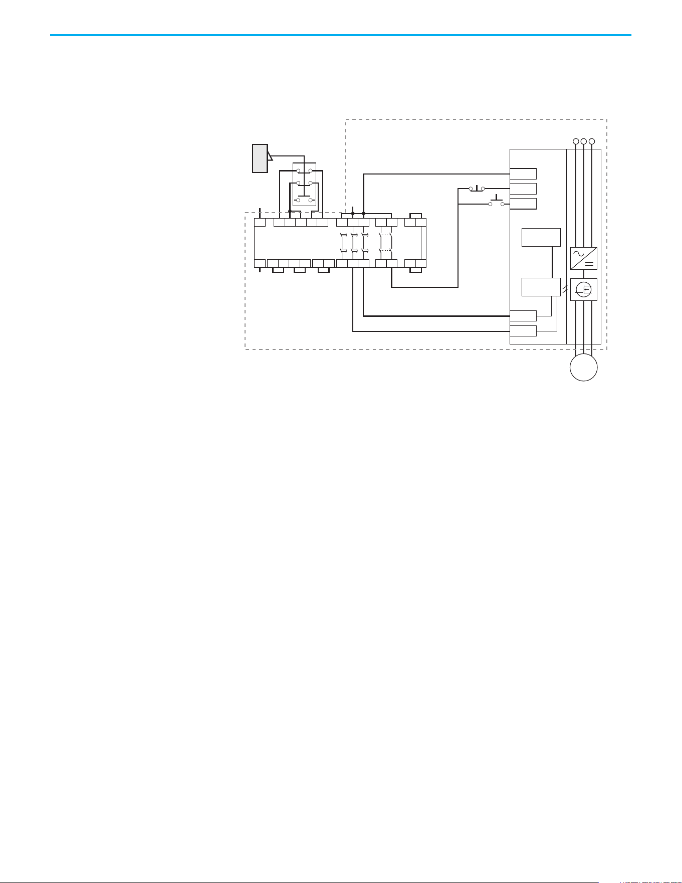
Rockwell Automation Publication 520-UM001N-EN-E - July 2024 247
Appendix G Safe Torque Off Function
Example 2 – Safe Torque Off Connection with Controlled Stop Action,
SIL 2/PLd
Stop Category 1 – Controlled
(1) An enclosure is recommended. External wiring failure modes must be considered as described in EN ISO 13849-2. Use an
enclosure or other measure to exclude these failure modes.
Circuit Status
The circuit is shown with the guard door closed and the system ready for
normal drive operation.
Operating Principle
This is a dual-channel system with monitoring of the Safe Torque Off circuit
and drive. Opening the guard door switches the input circuits (S11-S12 & S21-
S22) to the Minotaur monitoring safety relay unit. The output circuits (13-14)
will issue a Stop command to the drive and cause a controlled deceleration.
After the programmed delay, the timed output circuits (47-48 & 57-58) will
cause the Safe Torque Off Enable circuit to trip. If the motor is rotating when
the trip occurs, it will coast-to-stop. To restart the drive, the Minotaur safety
relay must first be reset followed by a valid start command to the drive.
Fault Detection
A fault that is detected on the Minotaur safety input circuits will result in the
lockout of the system at the next operation and will not cause loss of the safety
function.
A fault that is detected on the PowerFlex 525 safety enable redundant inputs
will result in the lockout of the drive and will not cause the loss of the safety
function.
24V DC
Common
+24V DC
GuardMaster
Trojan
Stop
Start
A1 S21 S11 S52 S12
A2 X1 X2
13 23
14 24
S33
Y2
S34
Y1X3
37 47 57
38 48 58X4
S22
Y39 Y40
Minotaur
MSR138DP
Gate
+24V DC
PF 525
Stop
Start
Gate control
power supply
Gate control
circuit
AC line
input power
S1
S2
M
(1)
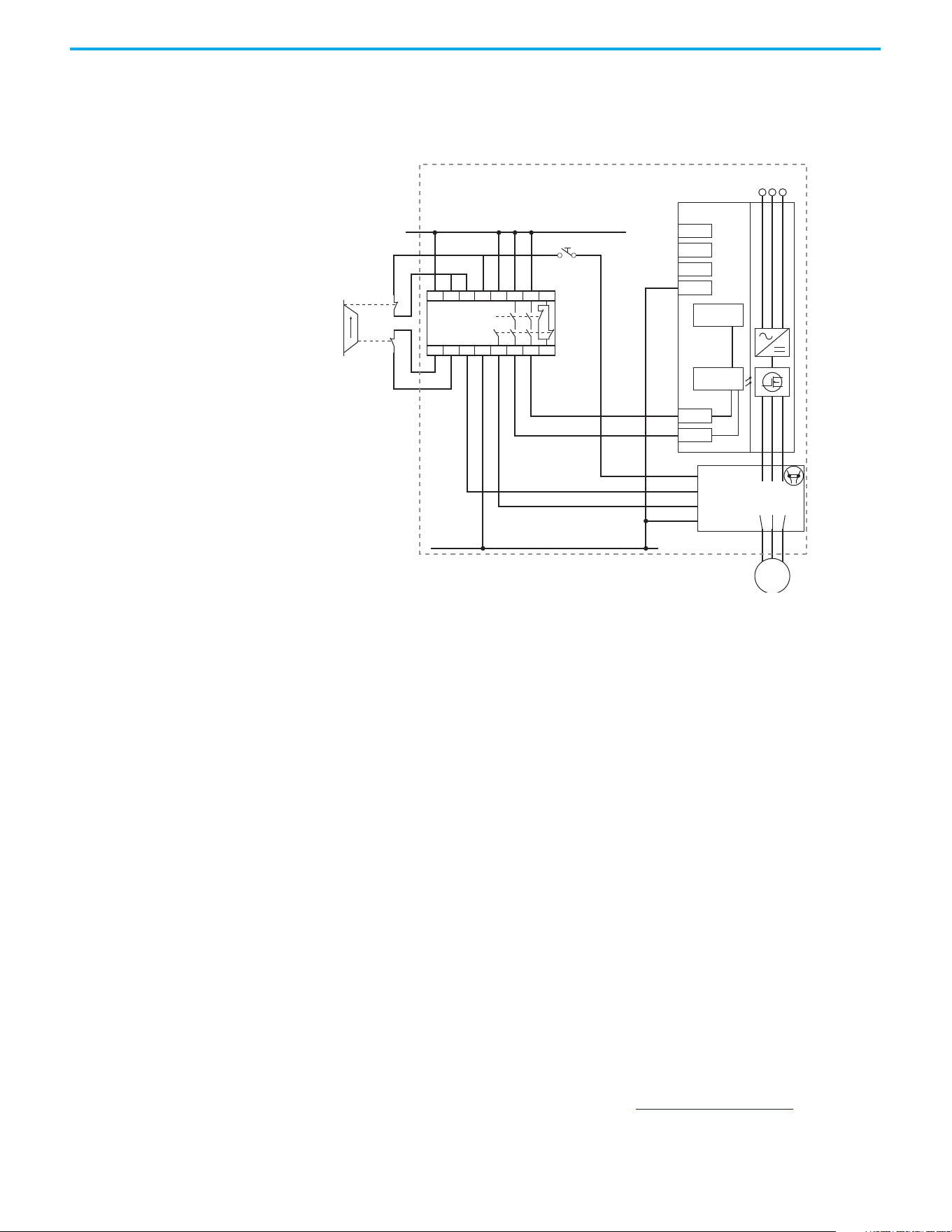
248 Rockwell Automation Publication 520-UM001N-EN-E - July 2024
Appendix G Safe Torque Off Function
Example 3 – Safe Torque Off Connection with Coast-to-Stop Action
Using External +24V supply, SIL 3/PL e
Stop Category 0 – Coast
(1) An enclosure is recommended. External wiring failure modes must be considered as described in EN ISO 13849-2. Use an
enclosure or other measure to exclude these failure modes.
Circuit Status
The circuit is shown with the guard door closed and the system ready for
normal drive operation.
Operating Principle
This is a dual-channel system with monitoring of the Safe Torque Off circuit
and drive. Opening the guard door switches the input circuits (S11-S12 & S21-
S22) to the Minotaur monitoring safety relay unit. The output circuits (13-14 &
23-24 & 33-34) will cause the output contact and Safe-Torque-Off Enable circuit
to trip and the motor will coast-to-stop. To restart the drive, the Minotaur
safety relay must first be reset followed by a valid start command to the drive.
Fault Detection
A fault that is detected on the Minotaur safety input circuits will result in the
lockout of the system at the next operation and will not cause loss of the safety
function.
PowerFlex 525 Certification
for Safe Torque Off
Certification information can be viewed at rok.auto/certifications.
Closed
Open
External +24V DC
24V DC COM
MSR127TP
Reset
+24V DC
PF 525
Stop
Start
COM
Gate control
power supply
Gate control
circuit
AC line
input power
S1
S2
X1 AUX
X2
A1 Coil
A2
External
contactor
100-C
100S-C
13 23 33
14 24 34
M
A1 S11 S52 S12 13 23 33 41
S21 S22 S34 A2 14 24 34 42
(1)

Rockwell Automation Publication 520-UM001N-EN-E - July 2024 249
Appendix H
EtherNet/IP
This section contains only basic information to setup an EtherNet/IP
connection with your PowerFlex 520-series drive. For comprehensive
information about EtherNet/IP (single and dual-port) and how to use it, see
the following publications:
• PowerFlex 525 Embedded EtherNet/IP Adapter User Manual, publication
520COM-UM001
.
• PowerFlex 25-COMM-E2P Dual-Port EtherNet/IP Adapter User Manual,
publication 520COM-UM003
.
It is recommended to use Allen-Bradley Ethernet RJ45 cables, shielded or
unshielded (catalog number 1585J-M8xBJM-x), for connecting your
PowerFlex 520-series drive to an EtherNet/IP network.
Establishing A Connection
With EtherNet/IP
There are three methods for configuring the Ethernet IP address:
• BootP Server – Use BootP if you prefer to control the IP addresses of
devices using a server. The IP address, subnet mask, and gateway
addresses will then be provided by the BootP server.
• Adapter Parameters – Use adapter parameters when you want more
flexibility in setting up the IP address, or need to communicate outside
the control network using a gateway. The IP address, subnet mask, and
gateway addresses will then come from the adapter parameters you set.
• DHCP (Dynamic Host Configuration Protocol) (only with PowerFlex 25-
COMM-E2P adapter) – Use DHCP when you want additional flexibility
and ease-of-use compared to BOOTP in configuring the IP address,
subnet mask, and gateway address for the adapter using a DHCP server.
ATTENTION: PowerFlex 523 drives support only the 25-COMM-E2P dual-port
EtherNet/IP adapter. PowerFlex 525 drives support both the embedded
EtherNet/IP adapter and the 25-COMM-E2P dual-port EtherNet/IP adapter.
IMPORTANT
If you are setting your network addresses manually using parameters,
you must set the appropriate drive or 25-COMM-E2P adapter parameter
value to 1 “Parameters”. See the respective EtherNet/IP adapter user
manual for more information.
IMPORTANT
Regardless of the method used to set the adapter IP address, each node
on the EtherNet/IP network must have a unique IP address. To change
an IP address, you must set the new value and then remove and reapply
power to (or reset) the adapter.
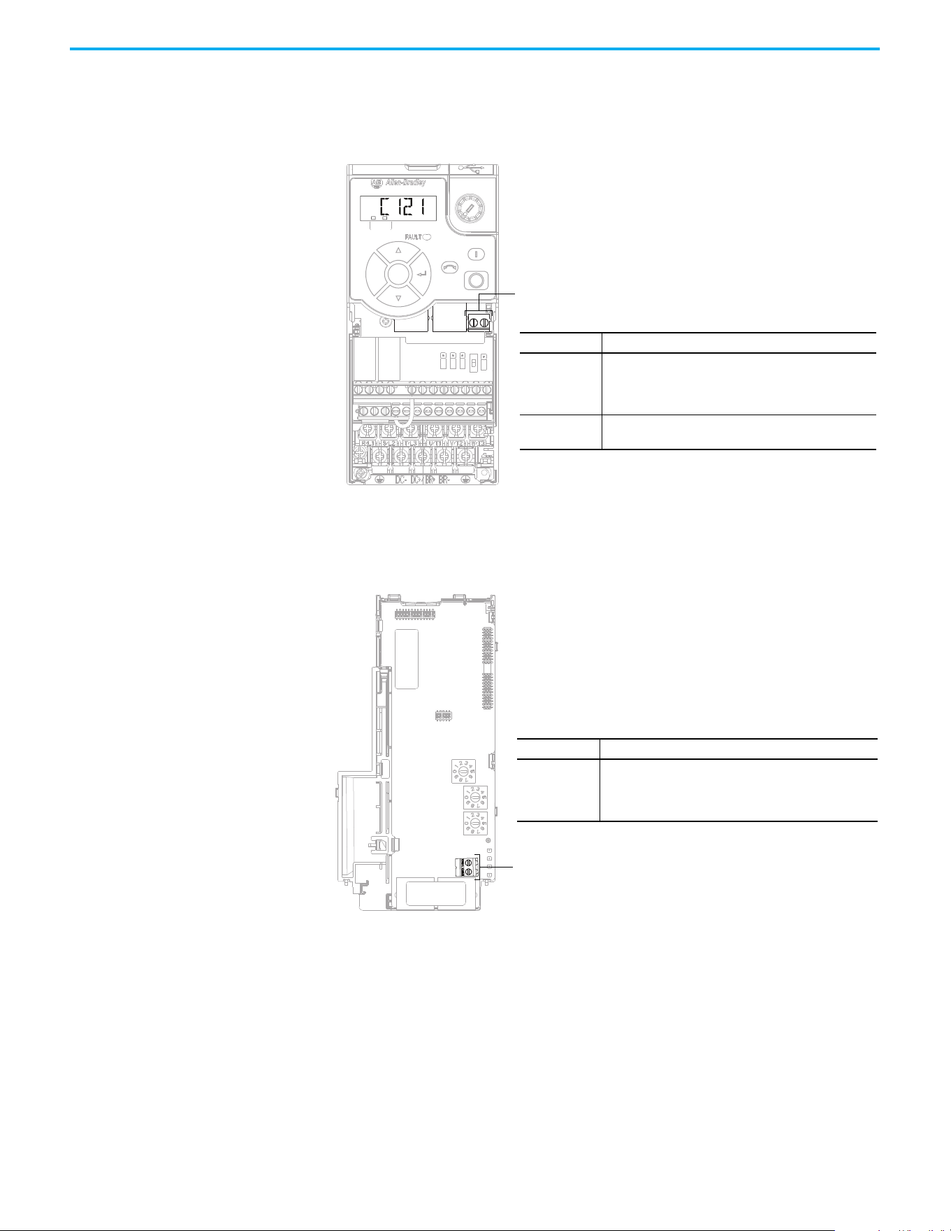
250 Rockwell Automation Publication 520-UM001N-EN-E - July 2024
Appendix H EtherNet/IP
Ground Connections for
EtherNet/IP Networks
Connect terminal C1 to a clean ground when using a network with a star
topology. It is acceptable to ground both C1 and C2 terminals.
PowerFlex 525 Embedded Ethernet/IP Adapter
Connect terminal CS1 or CS2 to a clean ground when using a network with a
ring topology.
PowerFlex 25-COMM-E2P Dual-Port EtherNet/IP Adapter
F
W
D
ENET LINK
EtherNet/IP
Esc
Sel
Terminal Description
C1
This terminal is tied to the RJ-45 port shield. Tie this
terminal to a clean ground in order to improve noise
immunity when using external communication
peripherals.
C2
This is the signal common for the communication
signals.
Terminals C1/C2
Terminal Description
CS1/CS2
Provides a clean ground for the communication bus cable
shields.
CS1 or CS2 should be connected to a clean ground or PE
ground on the drive.
Terminals CS1/CS2
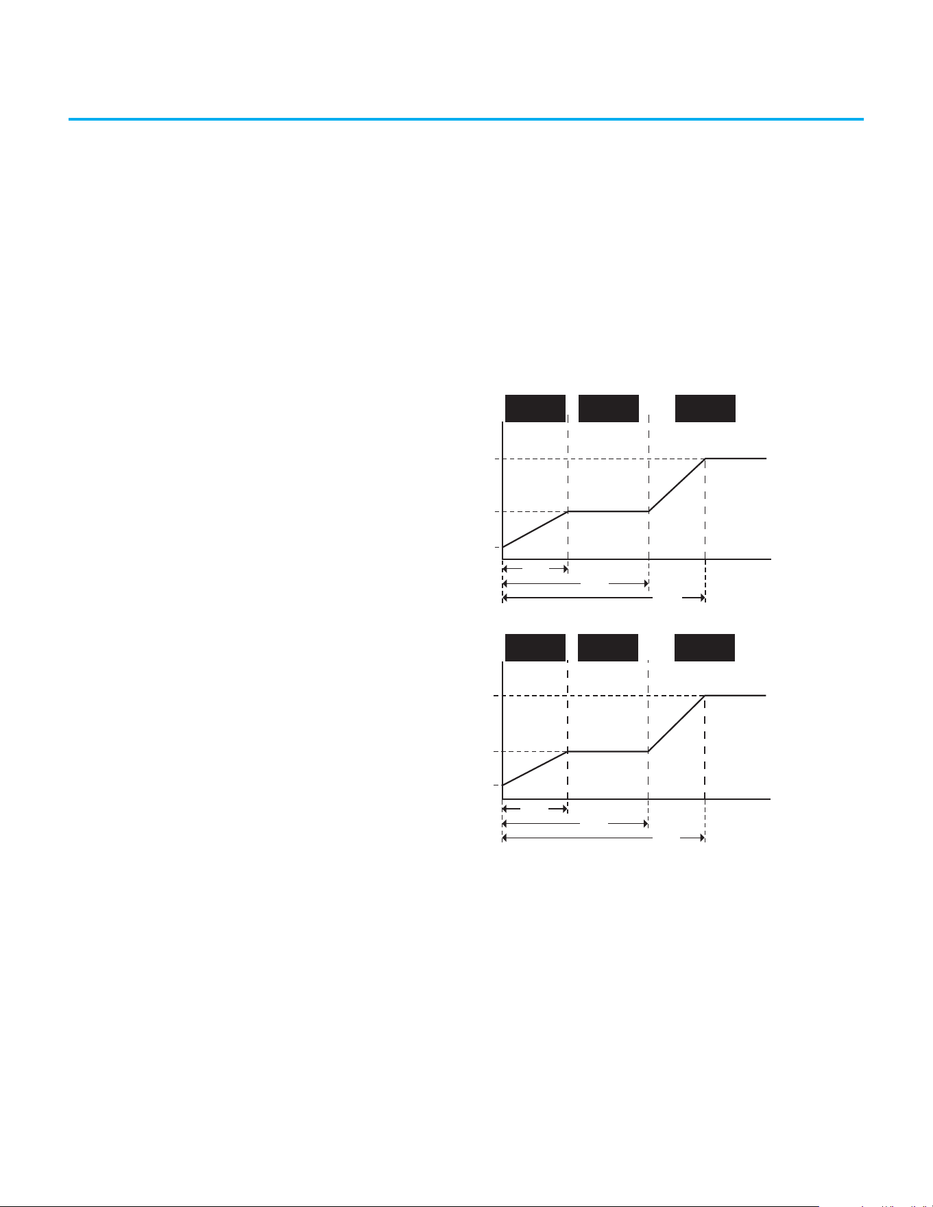
Rockwell Automation Publication 520-UM001N-EN-E - July 2024 251
Appendix I
Control Diagrams
This chapter contains various diagrams on the PowerFlex 520-series drive
functions and behaviors.
Induction Motor Tuning
Diagrams
[Speed Reg Sel] Diagrams For Motor Tuning
Speed Controller
Gain
Freq (Hz)
A515 [Freq 3 BW]
A513 [Freq 2 BW]
A511 [Freq 1 BW]
Low Speed
Control Mode
Mid Speed
Control Mode
High Speed
Control Mode
A509 [Speed Reg Sel] = 0
Gain set automatically
A512
[Freq 2]
A514
[ Freq 3]
A510
[Freq 1]
Speed Controller
Gain
A509 [Speed Reg Sel] = 1
Gain set manually
Freq (Hz)
A525 [Freq 3 Kp]
A526 [Freq 3 Ki]
A523 [Freq 2 Kp]
A524 [Freq 2 Ki]
A521 [Freq 1 Kp]
A522 [Freq 1 Ki]
A510
[Freq 1]
A512
[Freq 2]
A514
[Freq 3]
Low Speed
Control Mode
Mid Speed
Control Mode
High Speed
Control Mode
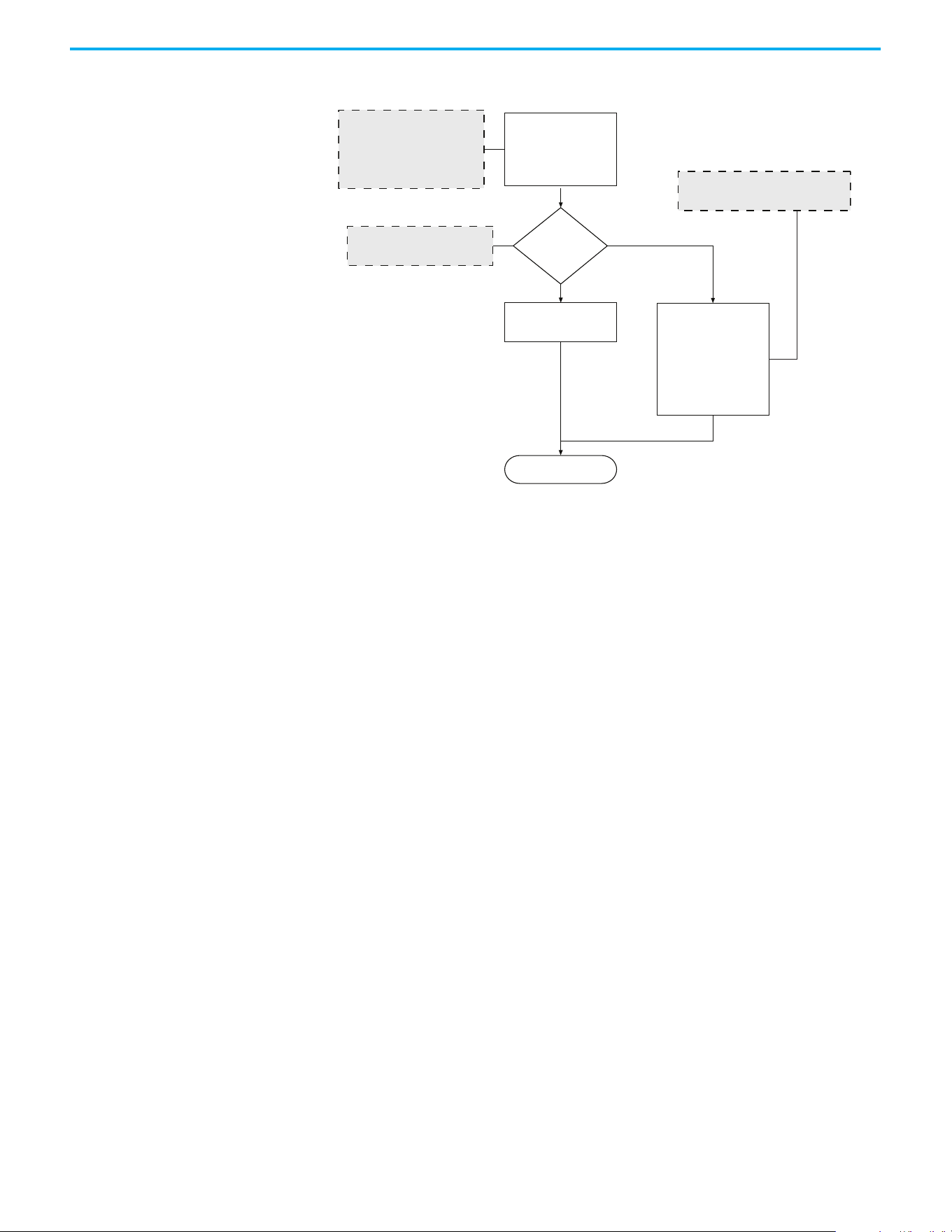
252 Rockwell Automation Publication 520-UM001N-EN-E - July 2024
Appendix I Control Diagrams
Adjusting Speed Control
Parameters
These settings show how to adjust the speed control for motor tuning.
Run
Speed Loop Bandwidth:
A511 [Freq 1 BW] = 10 Hz
A513 [Freq 2 BW] = 10 Hz
A515 [Freq 3 BW] = 10 Hz
Set Speed Controller Gain
automatically
A509 = 0 (Automatic)
A509 = 1 (Manual)
Set Speed Controller Gain
manually:
A521 [Freq 1 Kp]
A522 [Freq 1 Ki]
A523 [Freq 2 Kp]
A524 [Freq 2 Ki]
A525 [Freq 3 Kp]
A526 [Freq 3 Ki]
Increase the bandwidth to obtain
faster speed response. If oscillation
occurs, decrease the bandwidth.
For general use, set A509
[Speed Reg Sel] to 0 (Automatic)
Set A509
[Speed Reg Sel]
For [Freq x Kp], gradually increase by 1%
For [Freq x Ki], gradually increase by 0.1 s

Rockwell Automation Publication 520-UM001N-EN-E - July 2024 253
Appendix J
PowerFlex 525 PM Motor Configuration
This chapter contains instructions and diagrams on configuring the
PowerFlex 525 drive for use with a PM motor. For more information, see the
PowerFlex 525 Configuration with Permanent Magnet Motors Application
Technique, publication 520-AT001
.
To use PM motor control, you need to install the PowerFlex 525 drive firmware
revision 5.001 or later. If you wish to perform PM motor tuning by using the
PowerFlex 525 Startup Wizard in Connected Components Workbench
software, and update to the latest drive database.
ATTENTION: It is the responsibility of the startup engineer / end user to use
proper safety precautions with any equipment used during this startup.
In no event will Rockwell Automation, Inc. be responsible or liable for
indirect or consequential damages resulting from the use or application of
this equipment. The examples and diagrams in this document are included
solely for illustrative purposes. Because of the many variables and
requirements associated with any particular installation, Rockwell
Automation cannot assume responsibility or liability of actual use based on
the examples and diagrams.
No patent liability is assumed by Rockwell Automation, Inc. with respect to
the information, circuits, equipment. Or software described in this
document. Rockwell Automation reserves the right to make changes to this
document without prior notice. When using examples in this document the
user recognizes that Rockwell Automation cannot be made liable for any
damage or claims. Because there are many application-specific variables,
users MUST ensure that products are correctly used and the appropriate
architecture is deployed. Reproduction of the contents of this document, in
whole or in part, without written permission of Rockwell Automation, Inc. is
prohibited.
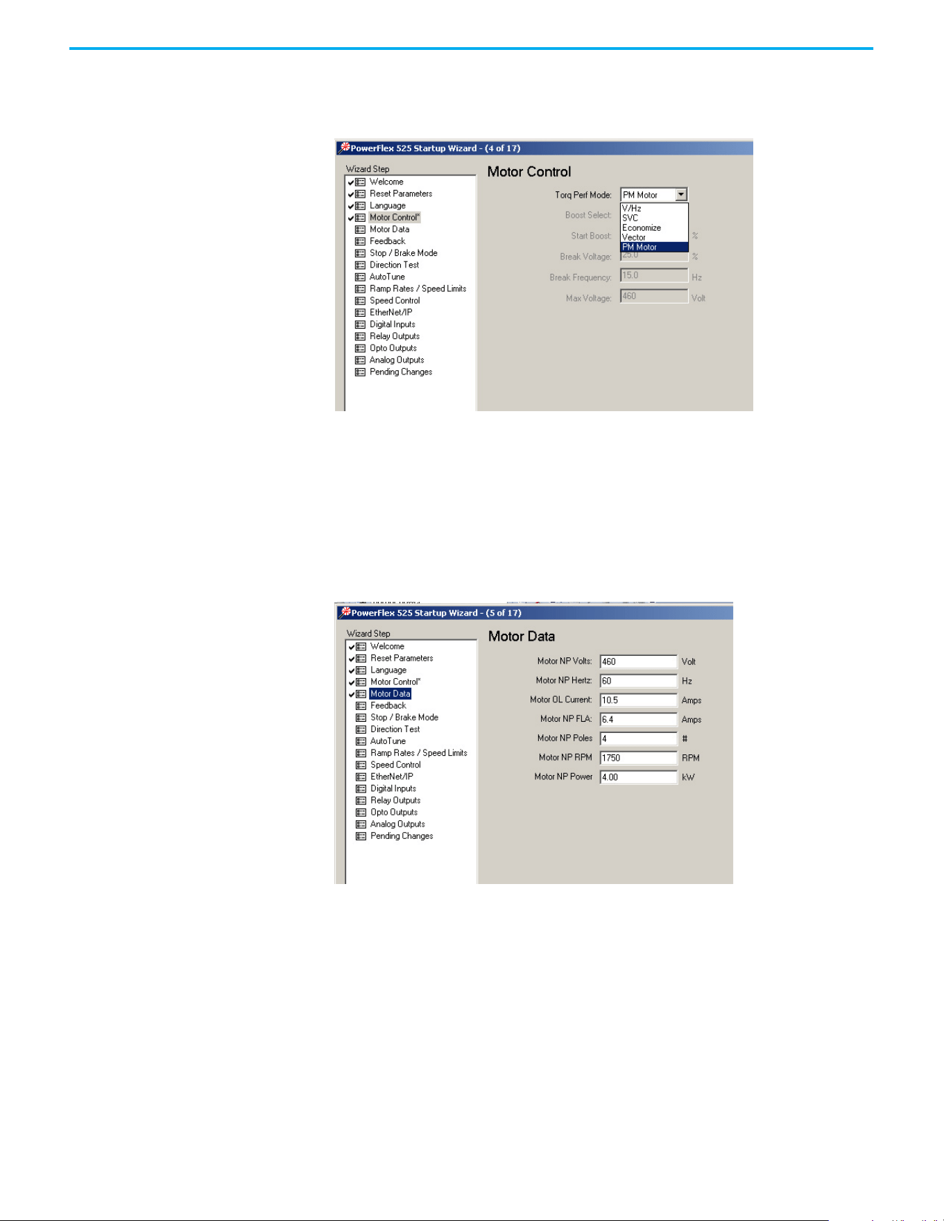
254 Rockwell Automation Publication 520-UM001N-EN-E - July 2024
Appendix J PowerFlex 525 PM Motor Configuration
Motor Control
From the Torq Perf Mode drop-down list, select “PM Motor”.
This configuration can also be done by setting parameter P039 [Torq Perf
Mode] to 4 “PM Motor”.
Motor Data
Key in the details of your Motor Nameplate.
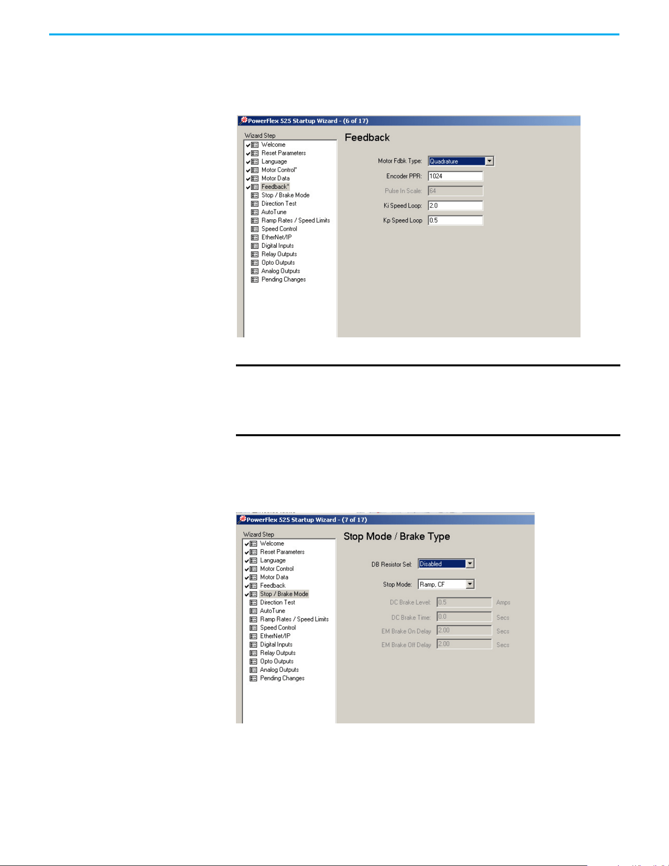
Rockwell Automation Publication 520-UM001N-EN-E - July 2024 255
Appendix J PowerFlex 525 PM Motor Configuration
Feedback
If you are configuring a closed loop PM motor control, key in the details of your
incremental encoder.
Stop Mode/Brake Type
Key in the details of your configuration.
IMPORTANT
Note the following:
• PowerFlex 525 drive only supports incremental AB encoder (25-ENC-1).
• Motor Feedback Type can be “Quadrature” or “Quad Check”.
• Only Interior Permanent magnet motor (iPM) is supported for closed loop
control.
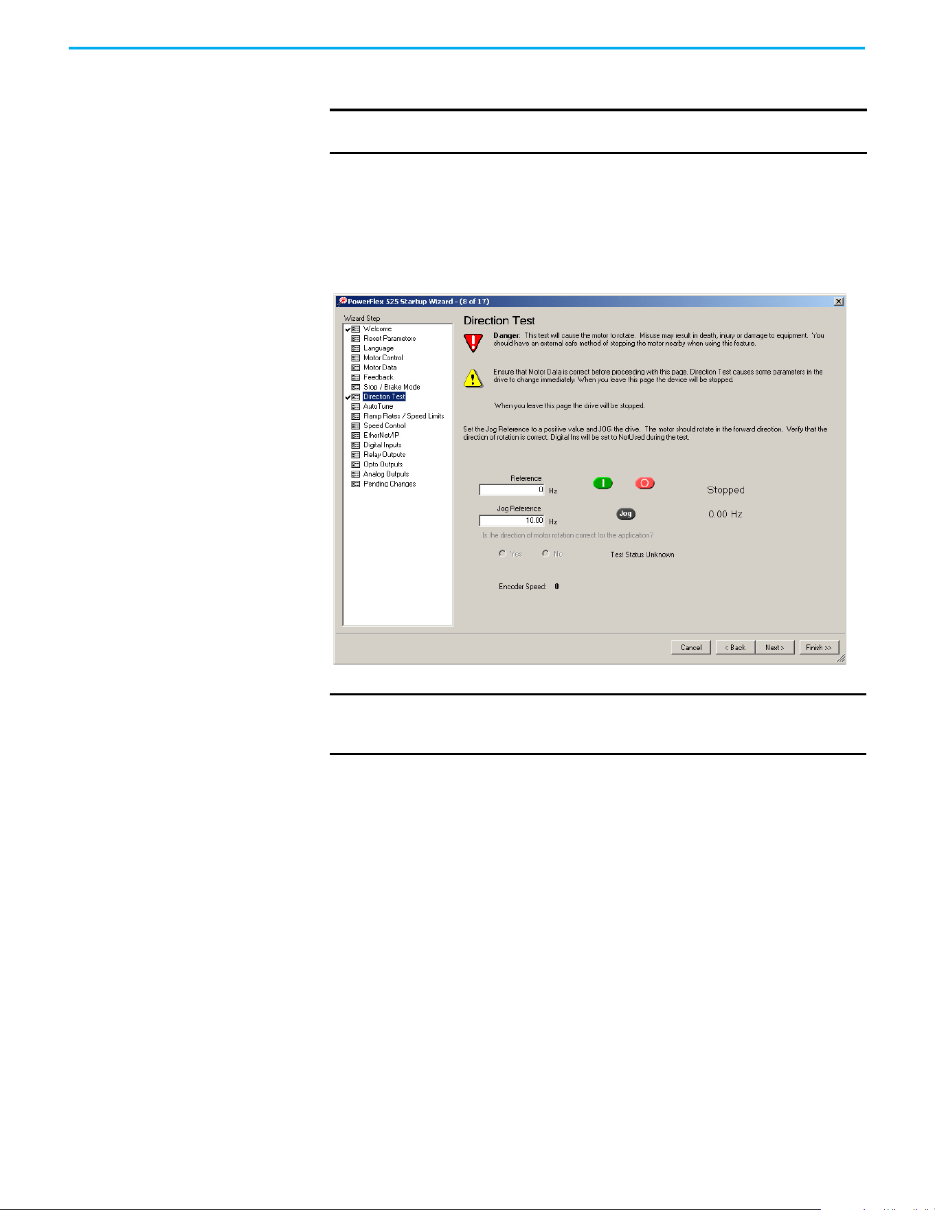
256 Rockwell Automation Publication 520-UM001N-EN-E - July 2024
Appendix J PowerFlex 525 PM Motor Configuration
Direction Test
Perform a Direction Test. The direction test can be performed with or without
the load attached. Consider your application requirements when deciding to
have the load attached or removed from the motor. This test runs in V/Hz
mode to verify the motor polarity relative to the feedback polarity. The test
confirms motor rotation and feedback polarity. After the test is completed, a
change can be made, if necessary.
Auto Tune
Ensure the load is uncoupled and perform a Rotate Tune test.
Run the drive with P040 [Autotune] = 2 “Rotate Tune” configured to
complete the auto tune process. This process measures and configures
the following:
•A501 [PM IR Voltage]
• A502 [PM IXd Voltage]
• A503 [PM IXq Voltage]
•A504 [PM BEMF Voltage]
The Auto Tune is used to identify the correct motor flux and stator electrical
properties, including the following:
• IR volt drop, which is voltage drop over resistance.
• IXd volt drop, which is voltage drop over inductance.
IMPORTANT
When configuring a PM motor or using an encoder, it is required to
perform a Direction Test before proceeding to the next step (Auto Tune).
IMPORTANT
If the drive was never operated before (new installation), verify that
safeguards are in place to remove power safely from the drive during
an unstable situation where the drive can produce undesired motion.
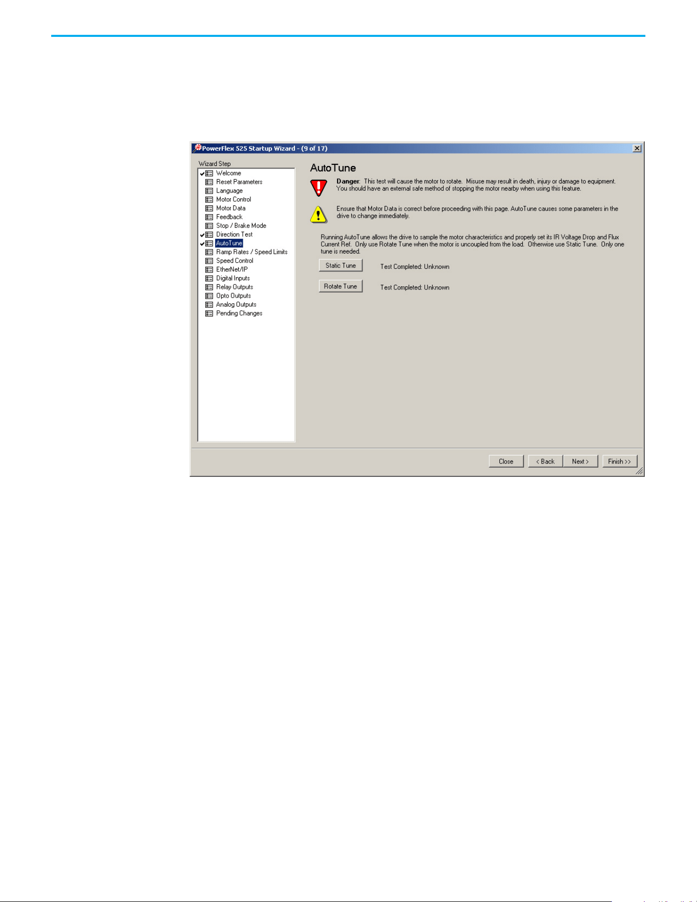
Rockwell Automation Publication 520-UM001N-EN-E - July 2024 257
Appendix J PowerFlex 525 PM Motor Configuration
• Flux current (estimated in Static Tune and measured in Rotate Tune
test).
• Slip RPM, which is calculated from motor nameplate data. If an encoder
is used, the Slip RPM becomes a measured value using the encoder.
Auto Tune Window
A properly tested motor and drive helps ensure higher starting torque and
better performance at low speeds. Conversely, an improperly performed Auto
Tune can cause the motor to exhibit instability at low speeds, uneven
performances when running through the motor speed range, and can generate
unnecessary faults such as overcurrent and overvoltage faults.
Static Tune
This test is used when the motor is connected to a high friction load and
cannot easily be uncoupled from the motor, or when the load cannot be rotated
due to mechanical constraints or a limited range of movement. The Static
Tune test does not generate any motor movement. The Static tune test results
may not be as accurate as the Rotate Tune test.
Rotate Tune (preferred for PM motor tuning)
This test is used when the motor is not coupled to the load or the load is low
friction. Rotate tune is generally used to better identify motor flux and stator
electrical properties, which are used to automatically tune the torque current
loop. The Rotate Tune test causes motor rotation at different speeds while it is
executing.

258 Rockwell Automation Publication 520-UM001N-EN-E - July 2024
Appendix J PowerFlex 525 PM Motor Configuration
After completing the configuration and running the Auto Tune test, you may
need to perform additional configuration depending on whether you have an
open loop or closed loop system.
For an open loop system (A535 [Motor Fdbk Type] = 0 “None”), you may need to
adjust two parameters if you encounter momentary reverse startup after a
Start command is issued.
For a closed loop system (A535 [Motor Fdbk Type] = 4 “Quadrature” or 5 “Quad
Check”, you must perform an angle alignment after the Auto Tune test before
running the motor normally.
See Additional PM Motor Configuration on page 259
for instructions.
Manual Configuration Using
Drive Keypad
Besides using the PowerFlex 525 Startup Wizard in Connected Components
Workbench software, you can also manually configure the parameters by
using the drive keypad. Make sure you have installed the PowerFlex 525 drive
firmware revision 5.001 or later.
To configure the parameters, do the following:
1. Reset all parameters to their default values.
Set P053 [Reset to Defalts] = 2 “Factory Rset”
2. Select the Control Mode.
Set P039 [Torque Perf Mode] = 4 “PM Control”
3. Enter Motor nameplate data:
• Set P031 [Motor NP Volts]
• Set P032 [Motor NP Hertz]
• Set P033 [Motor OL Current]
• Set P034 [Motor NP FLA]
• Set P035 [Motor NP Poles]
• Set P036 [Motor NP RMP]
• Set P037 [Motor NP Power]
• Set P043 [Minimum Freq]
• Set P044 [Maximum Freq]
4. Set A440 [PWM Frequency] = 4.0 kHz (default).
5. Set A535 [Motor Fdbk Type]:
• = 4 “Quadrature” or 5 “Quad Check” (for Closed Loop PM)
or
• = 0 “None” (for Open Loop PM)
• A536 [Encoder PPR]
6. Enter Stop mode and dynamic brake data, if any.
• P045 [Stop Mode]
• A437 [DB Resistor Sel]
7. Ensure the load is uncoupled and perform a Rotate Tune test.
Set P040 [Autotune] = 2 “Rotate Tune”
ATTENTION: If the drive was never operated before (new installation),
verify that safeguards are in place to remove power safely from the drive
during an unstable situation where the drive can produce undesired motion.

Rockwell Automation Publication 520-UM001N-EN-E - July 2024 259
Appendix J PowerFlex 525 PM Motor Configuration
Press the Start button (Take note of your Start Source settings P046,
P048, and P050. Default setting of P046 = 1 “Keypad”)
After completing the configuration and running the Auto Tune test, you may
need to perform additional configuration depending on whether you have an
open loop or closed loop system.
For an open loop system (A535 [Motor Fdbk Type] = 0 “None”), you may need to
adjust two parameters if you encounter momentary reverse startup after a
Start command is issued.
For a closed loop system (A535 [Motor Fdbk Type] = 4 “Quadrature” or 5 “Quad
Check”, you must perform an angle alignment after the Auto Tune test before
running the motor normally.
See Additional PM Motor Configuration on page 259
for instructions.
Additional PM Motor
Configuration
After completing the initial configuration, there are additional steps that need
to be performed to complete the whole PM motor setup.
For an open loop PM motor (iPM and sPM) control, some parameters need to
be adjusted to prevent reverse startup. For a closed loop PM motor (iPM), an
angle alignment procedure needs to be performed before the motor is run
normally.
Additional Setup for Open Loop PM Motor
After performing an auto tune on an open loop PM motor, a momentary
“reverse startup” may occur. To prevent this from occurring, perform the
following steps:
1. Set A516 [PM Initial Sel] = 1 “HFI”.
2. Increase the value of A519 [PM HFI NS Cur] by 10%.
3. Perform a test run at a reference speed and check if the motor reverses.
4. If the motor reverses, repeat steps 2 and 3.
5. If A519 [PM HFI NS Cur] has reached its maximum value (200%):
• reset the value to the default (100%)
• set A516 [PM Initial Sel] = 2 “Six Pulse”
6. Perform a test run at a reference speed and check if the motor reverses.
7. If the motor reverses, repeat steps 2 and 3.
8. If A519 [PM HFI NS Cur] has reached its maximum value again and a
reverse motor startup still occurs, the motor setup has failed.
ATTENTION: If the drive was never operated before (new installation),
verify that safeguards are in place to remove power safely from the drive
during an unstable situation where the drive can produce undesired
motion.
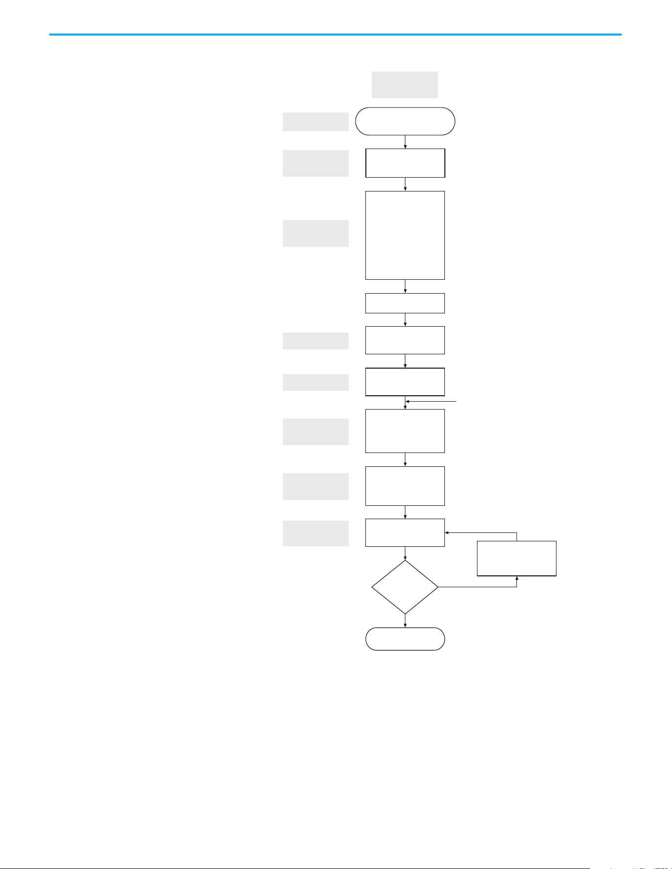
260 Rockwell Automation Publication 520-UM001N-EN-E - July 2024
Appendix J PowerFlex 525 PM Motor Configuration
Flowchart for Open Loop PM Motor (iPM and sPM) Setup
Drive is aligned and
ready to run
A535 [Motor Fdbk Type]
= 0 (None)
Set PG
P053 [Reset to Defalts]
= 2 (Factory Reset)
P039 [Torque Perf Mode]
= 4 (PM Control)
A440 [PWM Frequency]
P040 [Autotune]
= 2 (Rotate Tune)
Start Autotune
A501 [PM IR Voltage]
A502 [PM IXd Voltage]
A503 [PM IXq Voltage]
A504 [PM BEMF Voltage]
P031 [Motor NP Volts]
P032 [Motor NP Hertz]
P033 [Motor OL Current]
P034 [Motor NP FLA]
P035 [Motor NP Poles]
P036 [Motor NP RPM]
P037 [Motor NP Power]
P043 [Minimum Freq]
P044 [Maximum Freq]
Set Autotune
Reverse Startup
Check
Control Mode
Selection
Load Default
Basic Setting
Set Motor
Parameters
Repeat steps 2 and 3 of
Additional Setup for
Open Loop PM Motor
No
Yes
Perform a test run at
command frequency
Obtain Parameters
from Autotune
P041 [Accel Time 1]
P042 [Decel Time 1]
A439 [S Curve %]
Set Accel and
Decel Time
Do you see
reverse startup?

Rockwell Automation Publication 520-UM001N-EN-E - July 2024 261
Appendix J PowerFlex 525 PM Motor Configuration
Additional Setup for Closed Loop PM Motor
After performing an auto tune on an closed loop PM motor, a PM angle
alignment needs to be performed to complete the setup.
Align the PM Angle
To align the PM angle, do the following:
1. Uncouple the load.
2. Set these parameters to the recommended value:
•A517 [PM DC Inject Cur] = 60% (default is 30%)
• A518 [PM Align Time] = 5.8 s (default is 0.7 s)
• A580 [Current Loop BW] = 300 Hz (default is 0 Hz)
3. Set the desired speed (10...40 Hz recommended).
Check the setting for P047 [Speed Reference 1]. Speed reference can be
from POT, control panel of Connected Components Workbench
software, and so on.
4. Set the Start Source.
Check the setting for P046 [Start Source 1]. Start source can be from POT,
control panel of Connected Components Workbench software, and so
on.
5. Start the drive to run at the desired speed.
6. Drive will begin to align itself (move forward and reverse) and run to the
desired speed.
7. Stop the drive. The drive is now aligned.
Adjustments if PM Angle Alignment has Failed
If the PM angle alignment has failed, do the following:
1. Cycle drive power or set A535 [Motor Fdbk Type] = 0 “None”, then set back
to 4 “Quadrature” or 5 “Quad Check”.
2. Increase A517 [PM DC Inject Cur] by 50%.
3. Increase A518 [PM Align Time] by 0.2 s.
4. Repeat the Align the PM Angle
instructions again, beginning from step 3.
The PM angle alignment only needs to be performed once unless the
drive is power cycled or re-tuned.
IMPORTANT
The PM angle alignment has failed when fault F012 (HW Overcurrent) or
F013 (Ground Fault) is observed during acceleration and deceleration.
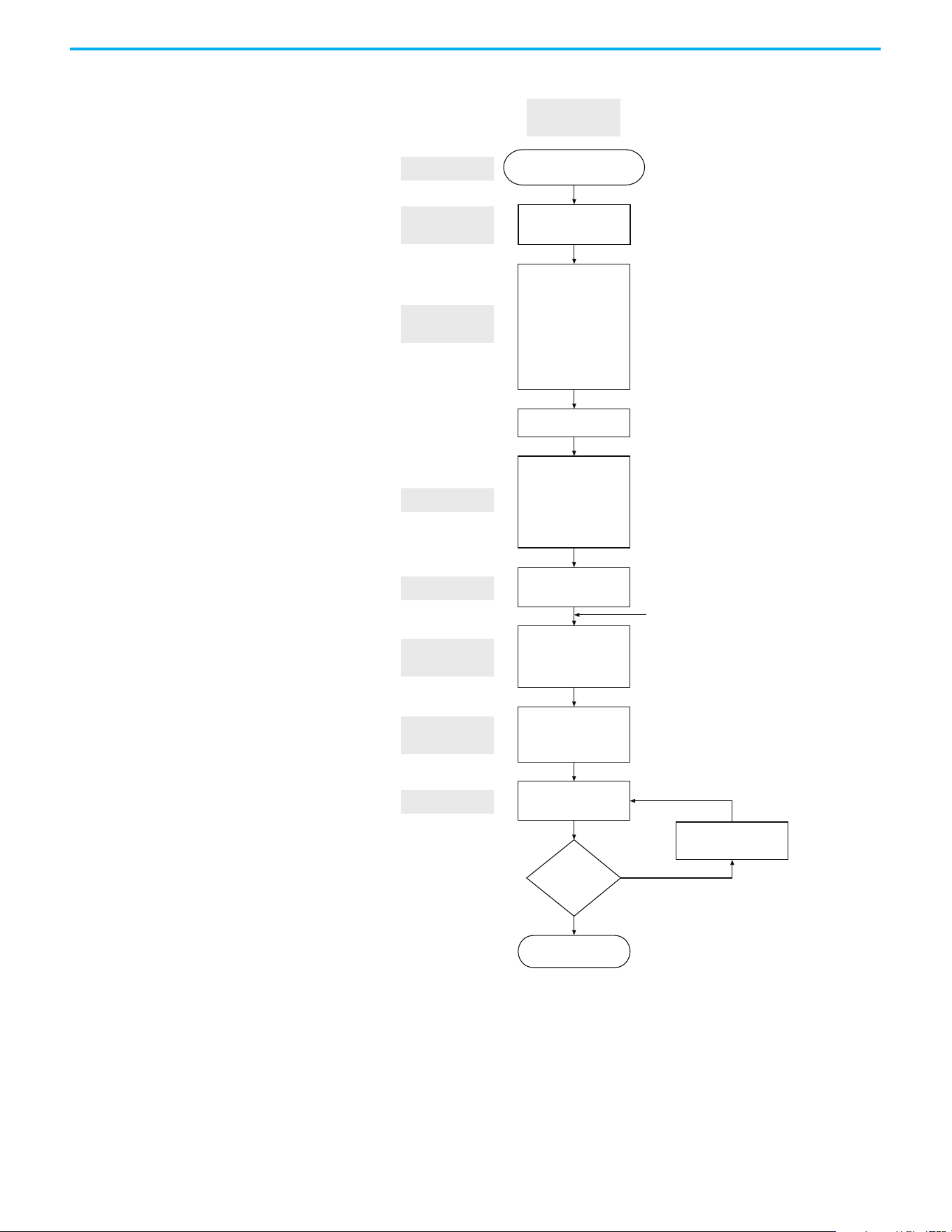
262 Rockwell Automation Publication 520-UM001N-EN-E - July 2024
Appendix J PowerFlex 525 PM Motor Configuration
Flowchart for Closed Loop PM Motor (iPM) Setup
Drive is aligned and
ready to run
A536 [Encoder PPR]
A518 [Align Time]
A517 [PM DC Inject Cur]
A535 [Motor Fdbk Type]
= 4 (Quadrature)
or 5 (Quad Check)
Set PG
P053 [Reset to Defalts]
= 2 (Factory Reset)
P039 [Torque Perf Mode]
= 4 (PM Control)
A440 [PWM Frequency]
P040 [Autotune]
= 2 (Rotate Tune)
Start Autotune
A501 [PM IR Voltage]
A502 [PM IXd Voltage]
A503 [PM IXq Voltage]
A504 [PM BEMF Voltage]
P031 [Motor NP Volts]
P032 [Motor NP Hertz]
P033 [Motor OL Current]
P034 [Motor NP FLA]
P035 [Motor NP Poles]
P036 [Motor NP RPM]
P037 [Motor NP Power]
P043 [Minimum Freq]
P044 [Maximum Freq]
Set Autotune
Set Alignment
Control Mode
Selection
Load Default
Basic Setting
Set Motor
Parameters
See Adjustments if PM Angle
Alignment has Failed
Yes
No (Fault F012 or F013 is observed
during acceleration and deceleration.)
Set alignment
See Align the PM Angle
Obtain Parameters
from Autotune
P041 [Accel Time 1]
P042 [Decel Time 1]
A439 [S Curve %]
Set Accel and
Decel Time
Does drive
align successfully?

Rockwell Automation Publication 520-UM001N-EN-E - July 2024 263
Appendix J PowerFlex 525 PM Motor Configuration
Optional Parameter
Adjustments for Optimum
Performance
There are a few parameters that you can use to obtain optimum performance
during the test run. Usually, the default value of these parameters work well,
but you may need to adjust them under different conditions.
1. A517 [PM DC Inject Cur]
Maximum DC current in amps applied to the motor in order to reset the
rotor position of a PM motor.
Alignment has failed when fault F012 (HW Overcurrent) or F013 (Ground
Fault) is observed during acceleration and deceleration.
Default = 30%
Increase 50 of A517 [PM DC Inject Cur] for each trial when PM speed
response is slow after adding load.
2. A518 [PM Align Time]
Magnetic pole reorientation time.
Alignment failed when fault F012 (HW Overcurrent) or F013 (Ground
Fault) is observed during acceleration and deceleration.
Default = 0.7 s
Increase A518 [PM Align Time] to > 4.7 s.
3. A527 [PM FWKn 1 Kp]
The gain to ensure good performance in field weakening region.
Default = 450%
Increase 100 of A527 [PM FWKn 1Kp] for each trial when PM speed
response is slow after adding load.
Decrease 100 of A527 [PM FWKn 1Kp] for each trial when speed vibration
is observed after adding load.
4. A580 [Current loop BW]
Current loop bandwidth (0 = Auto calculate the control gain of current
loop)
Default = 0 Hz
Increase 50 of A580 [Current Loop BW] for each trial when PM speed
response is slow after adding load.
Decrease 50 of A580 [Current Loop BW] for each trial when speed
instability is observed after adding load.
5. A584 [PM Stable 2 Kp]
The gain for stabilization loop.
Default = 250%
Increase 100 of A584 [PM Stable 2 Kp] for each trial if fault F064 (Drive
overload) is experienced at high load.
Applicable to open loop tuning especially for sPM motor. In most cases,
the default value will work.

264 Rockwell Automation Publication 520-UM001N-EN-E - July 2024
Appendix J PowerFlex 525 PM Motor Configuration
Notes:
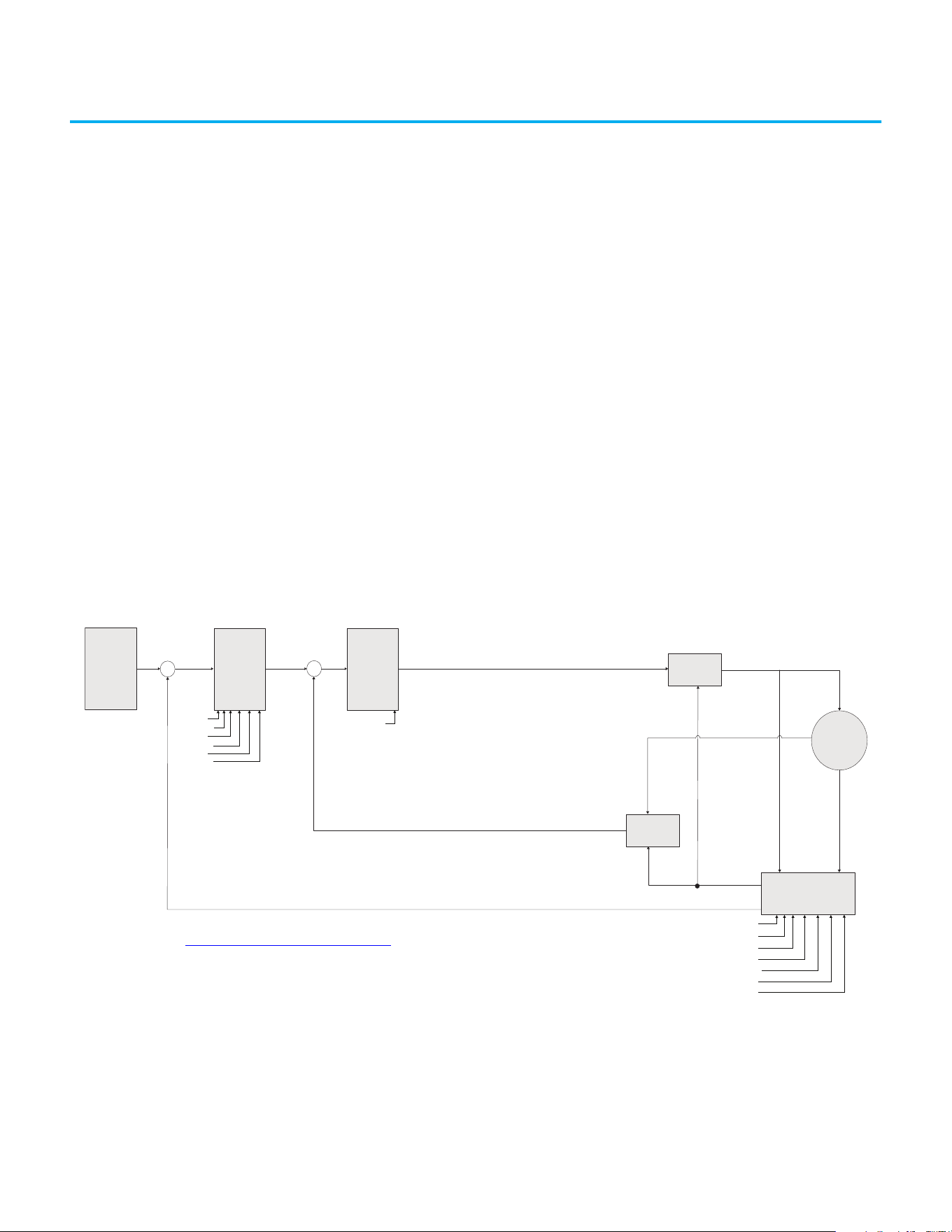
Rockwell Automation Publication 520-UM001N-EN-E - July 2024 265
Appendix K
PowerFlex 525 Synchronous Reluctance Motor
Configuration
This chapter contains instructions and diagrams on configuring the
PowerFlex 525 drive for use with a Synchronous Reluctance Motor (SynRM)
control.
PowerFlex 525 drive is enhanced with SynRM control that allows an option to
pair with PF525 SynRM for energy efficiency and low effort in motor
maintenance.
SynRM Structure Control Diagram
With PowerFlex 525 drive firmware revision 7.001, SynRM control can only be
configured manually using the keypad.
Speed / Theta
estimated
+
-
+
-
Speed
Reference
(Keyboard,
2-wire,
digital ...)
P1 Regulator
Speed
cmd
Current
cmd
P1 Regulator
Speed Loop
Current Loop
Voltage
out
abc/dq
Current
feedback
dq/abc
Motor
A510 [Freq 1]
A511 [Freq 1 BW]
A512 [Freq 2]
A513 [Freq 2 BW]
A514 [Freq 3]
A515 [Freq 3 BW]
A590 [SYNRM SW Freq]
A591 [SYNRM Flux Cur]
A592 [SYNRM Freq1 Volt]
A593 [SYNRM Freq1 Kp]
A594 [SYNRM Freq1 Comp]
A595 [SYNRM Freq2 BW]
A596 [SYNRM Freq2 Kp]
A580 [Current Loop BW]
Theta
Speed
See Adjusting Speed Control Parameters on page 252 for more information on speed loop bandwidth
adjustment.
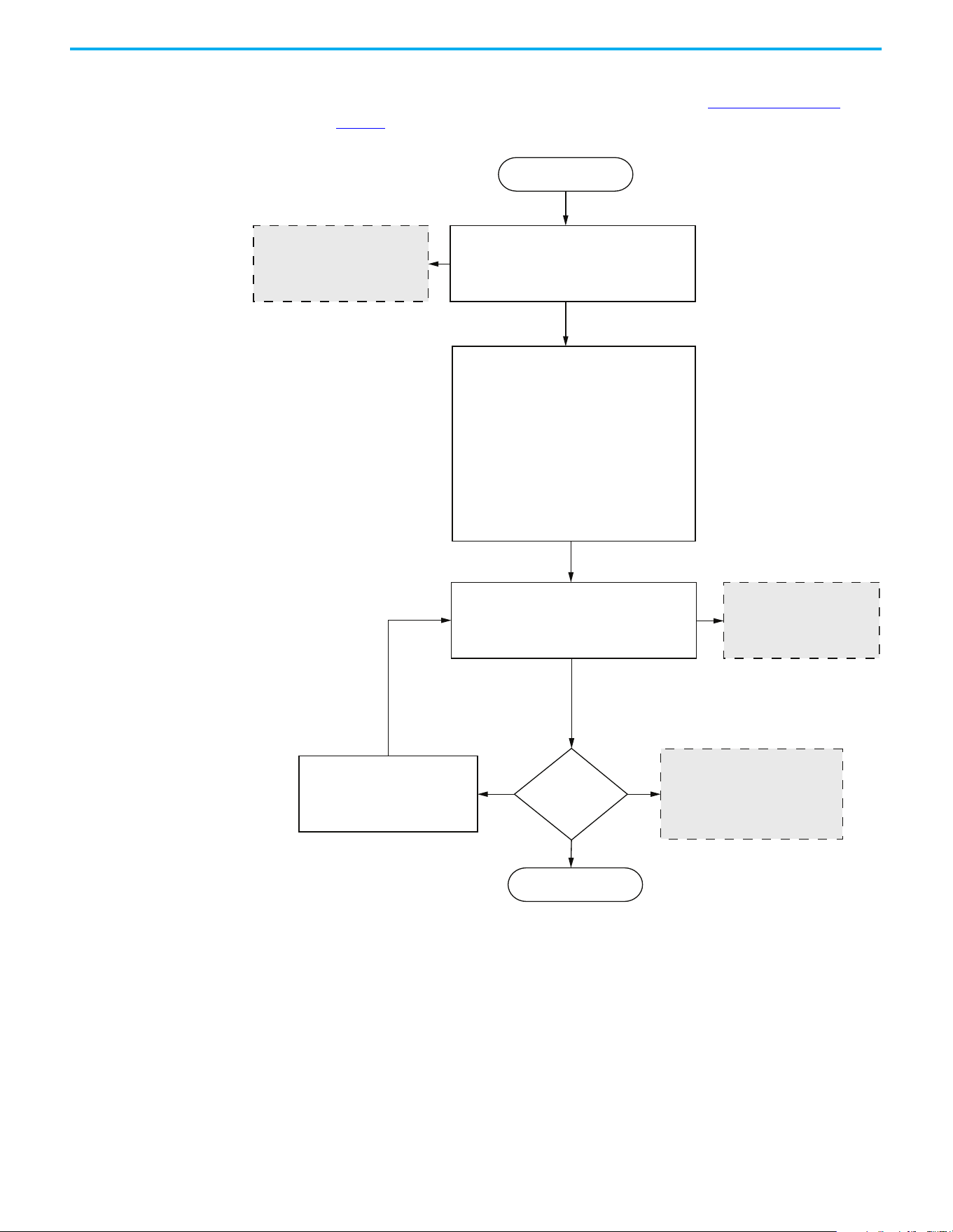
266 Rockwell Automation Publication 520-UM001N-EN-E - July 2024
Appendix K PowerFlex 525 Synchronous Reluctance Motor Configuration
SynRM Control
Configuration
To run the motor test, make sure you have installed the PowerFlex 525 drive
firmware revision 7.001 or later. For instructions, see Download Files on
page 11.
Select the Control Mode:
Set P039 [Torque Perf Mode] = 5 “SynRm”
Increase the bandwidth to obtain
faster speed response. If oscillation
occurs, decrease the bandwidth.
No SynRM parameters
Is the motor
auto-tuning
successful?
Check the following motor parameters:
A501 [PM IR Voltage]
A502 [PM IXd Voltage]
A503 [PM IXq Voltage]
A504 [PM BEMF Voltage]
Start
Set the motor parameters setting:
Rated Voltage: P031 [Motor NP Volts]
Rated Frequency: P032 [Motor NP Hertz]
OL Current: P033 [Motor OL Current]
Rated Current: P034 [Motor NP FLA]
Pole Numbers: P034 [Motor NP Poles]
Rated RPM: P036 [Motor NP RMP]
Rated Power: P037 [Motor NP Power]
Minimum Frequency: P043 [Minimum Freq]
Maximum Frequency: P044 [Maximum Freq]
Set A484 [Current Limit 1]
recommended value: > 1.65 x Rated Motor Current
Motor Parameter Auto-Tuning:
Set P040 [Autotune] = 1 “Auto Tune”
Press Run
No-Load Run
Yes
No
Make sure that the motor leaves
the load during auto-tuning
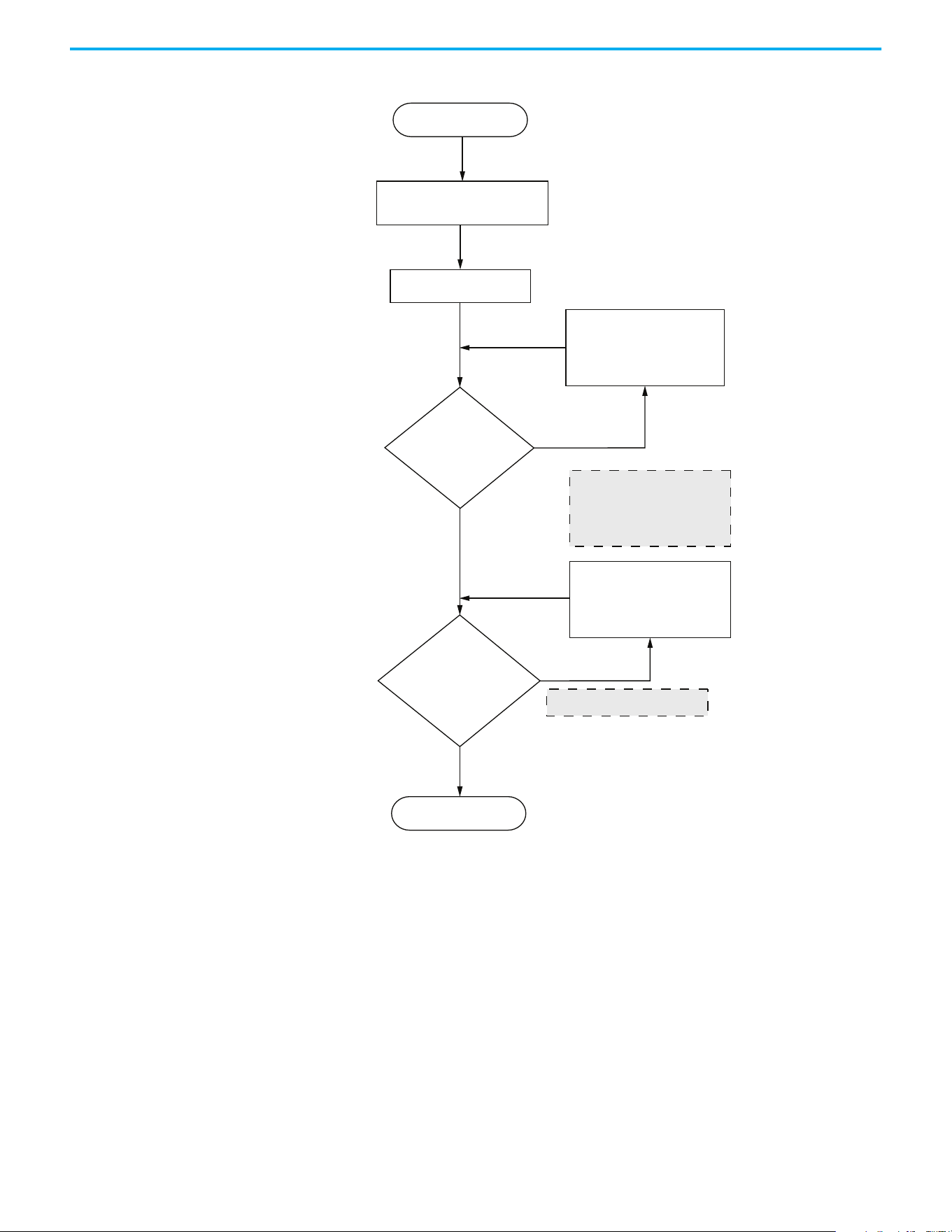
Rockwell Automation Publication 520-UM001N-EN-E - July 2024 267
Appendix K PowerFlex 525 Synchronous Reluctance Motor Configuration
Startup with No-Load adjustment procedure
Frequency command setting
higher than A590 [SYNRM SW Freq]
1. Increase A591 [SYNRM Flux Cur]
2. Adjust A595 [SYNRM Freq2 BW]
3. Adjust A596 [SYNRM Freq2 Kp]
Is the
speed stable and
does not oscillate before
A590
[SYNRM SW Freq]
?
No-Load Test
Motor starts running
Load operation test
Yes
No
1. The start-up direction is wrong
and causes F013 fault
2. Motor stalls
3. Motor speed vibrates extremely
• Increase A591 [SYNRM Flux Cur]
• Adjust A593 [SYNRM Freq1 Kp]
When the
frequency operation exceeds
A590 [SYNRM SW Freq],
is the speed stable and
does not oscillate?
No
Yes
Frequency speed vibration
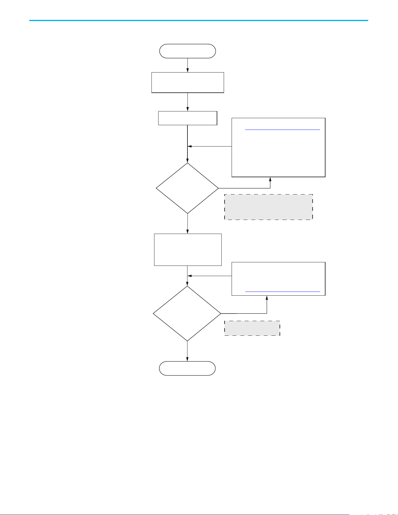
268 Rockwell Automation Publication 520-UM001N-EN-E - July 2024
Appendix K PowerFlex 525 Synchronous Reluctance Motor Configuration
Startup with Load adjustment procedure
Frequency command setting
higher than A590 [SYNRM SW Freq]
High-frequency loading
performance test
Is the
speed stable and
does not oscillate before
A590
[SYNRM SW Freq]
?
Load operation test
Motor starts running
Finish
Yes
No
1. Adjust the ASR Bandwidth
2. Adjust the A593 [SYNRM Freq1 Kp]
Transient load: If the speed drops
drastically, increase the setting to
improve the response.
Steady-state load: If there is extreme
frequency vibration, decrease the setting.
Did the high-frequency
loading performance
meet the request?
No
Insucient high-frequency
loading performance
1. When the motor increases the load at low
frequency, the speed drop is too large
2. Output frequency low frequency flutters
1. Adjust A595 [SYNRM Freq2 BW]
2. Adjust A596 [SYNRM Freq2 Kp]
3. Adjust ASR Bandwidth
Yes
See Induction Motor Tuning Diagrams on page 251
See Induction Motor Tuning Diagrams on page 251

Rockwell Automation Publication 520-UM001N-EN-E - July 2024 269
Index
Numerics
2-wire
inputs
50
3-wire
inputs
50
A
accel
override priority
51
selecting 51
accessing
control terminals
31
power terminals
32
applications
safety
241
auxiliary contact
drive
35, 36
B
basic operation 65
drive
59, 65, 164
programming
65
safety
244
C
circuit breakers
inputs
22
ratings
23
common bus
drive
36
communications
positioning
228
configuring
RS-485(DSI)
206
control terminals
accessing
31
counter
programming
213, 216
D
decel
override priority
51
selecting
51
derating
factor
126
temperature
17
digital inputs
selecting
50
start source
50
dimensions
mounting
15, 187
disconnect
output
35
drive
auxiliary contact
35, 36
basic operation
59, 65, 164
common bus
36
mount
15
programming
60, 64
safety
243
drive damage
preventing
19
ungrounded distribution systems
19
E
encoder
programming
219
wiring
221
environment
storage
18
Ethernet
programming
249
F
fault monitoring
ground
21
fuses
rating
22
G
ground
fault monitoring
21
motor
21
RFI filter 22
safety
21
shielding
21
H
homing
automatic
227
manual
226
programming
226
I
inputs
2-wire
50
3-wire
50
circuit breakers
22
power
20
L
logic
basic
213, 214
timed steps
213, 214

270 Rockwell Automation Publication 520-UM001N-EN-E - July 2024
Index
M
Modbus
reading
210, 211, 212
writing
207, 209, 212
motor
ground
21
start 35
stop
35
mount
drive
15
mounting
dimensions
15, 187
N
noise immunity
wiring
38, 206
O
output
disconnect
35
override priority
accel
51
decel 51
speed reference
49
start source
49
P
parameters
AppView
76, 152
CustomView
153
programming 63, 67
PID
programming
233
positioning
communications
228
programming 222, 223
power
inputs
20
power and control module
separating
29
power terminals
accessing
32
preventing
drive damage
19
programming
65
basic logic
213, 214
counter
213, 216
drive
60, 64
encoder
219
Ethernet
249
homing 226
parameters
63, 67
PID
233
positioning
222, 223
pulse train
219
timed steps
213, 214
timer
213, 215
tools
64
pulse train
programming
219
R
rating
fuses
22
ratings
circuit breakers
23
reading
Modbus
210, 211, 212
recommended
wiring
37, 243
reflected
wave protection
35
RFI filter
ground
22
RS-485(DSI)
configuring
206
S
safety
applications
241
basic operation
244
drive
243
ground
21
testing 242
wiring
243
selecting
accel
51
decel 51
digital inputs
50
speed reference
49
start source 49
separating
power and control module
29
shielded
wiring
34
shielding
ground
21
speed reference
override priority
49
selecting
49
start
motor
35
start source
digital inputs
50
override priority
49
selecting
49
stop
motor
35
storage
environment
18
T
temperature
derating
17
wiring
33
testing
safety
242
timer
programming
213, 215
tools
programming
64

Rockwell Automation Publication 520-UM001N-EN-E - July 2024 271
Index
U
unshielded
wiring
34
V
voltage reflections
wiring
35
W
wave protection
reflected
35
wiring
encoder
221
noise immunity
38, 206
recommended 37, 243
RS-485 (DSI)
205
safety
243
shielded 34
temperature
33
unshielded
34
voltage reflections
35
writing
Modbus
207, 209, 212

272 Rockwell Automation Publication 520-UM001N-EN-E - July 2024
Index
Notes:

Rockwell Automation Publication 520-UM001N-EN-E - July 2024 273
PowerFlex 520-series Adjustable Frequency AC Drive User Manual
Publication 520-UM001N-EN-E - July 2024
Supersedes Publication 520-UM001M-EN-E - January 2023 Copyright © 2024 Rockwell Automation, Inc. All rights reserved.
Rockwell Automation Support
Use these resources to access support information.
Documentation Feedback
Your comments help us serve your documentation needs better. If you have any suggestions on how to improve our content, complete the
form at rok.auto/docfeedback
.
Waste Electrical and Electronic Equipment (WEEE)
Rockwell Automation maintains current product environmental compliance information on its website at rok.auto/pec.
Technical Support Center
Find help with how-to videos, FAQs, chat, user forums, Knowledgebase, and product
notification updates.
rok.auto/support
Local Technical Support Phone Numbers Locate the telephone number for your country. rok.auto/phonesupport
Technical Documentation Center
Quickly access and download technical specifications, installation instructions, and user
manuals.
rok.auto/techdocs
Literature Library Find installation instructions, manuals, brochures, and technical data publications. rok.auto/literature
Product Compatibility and Download Center
(PCDC)
Download firmware, associated files (such as AOP, EDS, and DTM), and access product
release notes.
rok.auto/pcdc
At the end of life, this equipment should be collected separately from any unsorted municipal waste.
Rockwell Otomasyon Ticaret A.Ş. Kar Plaza İş Merkezi E Blok Kat:6 34752, İçerenköy, İstanbul, Tel: +90 (216) 5698400 EEE Yönetmeliğine Uygundur
Allen-Bradley, AppView, Compact I/O, Connected Components Workbench, CustomView, DriveTools, expanding human possibility, FactoryTalk, Logix 5000, MainsFree, Minotaur, PanelView,
PowerFlex, QuickView, Rockwell Automation, RSLogix, RSLogix 5000, SLC, StepLogic, Studio 5000, Studio 5000 Logix Designer, and TechConnect are trademarks of Rockwell Automation, Inc.
DeviceNet and EtherNet/IP are trademarks of ODVA, Inc.
Microsoft Windows is a trademark of Microsoft Corporation.
Trademarks not belonging to Rockwell Automation are property of their respective companies.