
User Manual
Original Instructions
PowerFlex 527 Adjustable
Frequency AC Drive
Bulletin Number 25C
2 Rockwell Automation Publication 520-UM002E-EN-E - September 2024
PowerFlex 527 Adjustable Frequency AC Drive User Manual
Important User Information
Read this document and the documents listed in the additional resources section about installation, configuration, and operation of this equipment before you
install, configure, operate, or maintain this product. Users are required to familiarize themselves with installation and wiring instructions in addition to
requirements of all applicable codes, laws, and standards.
Activities including installation, adjustments, putting into service, use, assembly, disassembly, and maintenance are required to be carried out by suitably trained
personnel in accordance with applicable code of practice.
If this equipment is used in a manner not specified by the manufacturer, the protection provided by the equipment may be impaired.
In no event will Rockwell Automation, Inc. be responsible or liable for indirect or consequential damages resulting from the use or application of this equipment.
The examples and diagrams in this manual are included solely for illustrative purposes. Because of the many variables and requirements associated with any
particular installation, Rockwell Automation, Inc. cannot assume responsibility or liability for actual use based on the examples and diagrams.
No patent liability is assumed by Rockwell Automation, Inc. with respect to use of information, circuits, equipment, or software described in this manual.
Reproduction of the contents of this manual, in whole or in part, without written permission of Rockwell Automation, Inc., is prohibited.
Throughout this manual, when necessary, we use notes to make you aware of safety considerations.
These labels may also be on or inside the equipment to provide specific precautions.
The following icon may appear in the text of this document.
WARNING: Identifies information about practices or circumstances that can cause an explosion in a hazardous environment, which
may lead to personal injury or death, property damage, or economic loss.
ATTENTION: Identifies information about practices or circumstances that can lead to personal injury or death, property damage,
or economic loss. Attentions help you identify a hazard, avoid a hazard, and recognize the consequence.
IMPORTANT Identifies information that is critical for successful application and understanding of the product.
SHOCK HAZARD: Labels may be on or inside the equipment, for example, a drive or motor, to alert people that dangerous voltage
may be present.
BURN HAZARD: Labels may be on or inside the equipment, for example, a drive or motor, to alert people that surfaces may reach
dangerous temperatures.
ARC FLASH HAZARD: Labels may be on or inside the equipment, for example, a motor control center, to alert people to potential Arc
Flash. Arc Flash will cause severe injury or death. Wear proper Personal Protective Equipment (PPE). Follow ALL Regulatory
requirements for safe work practices and for Personal Protective Equipment (PPE).
Identifies information that is useful and can help to make a process easier to do or easier to understand.

Rockwell Automation Publication 520-UM002E-EN-E - September 2024 3
Table of Contents
Preface
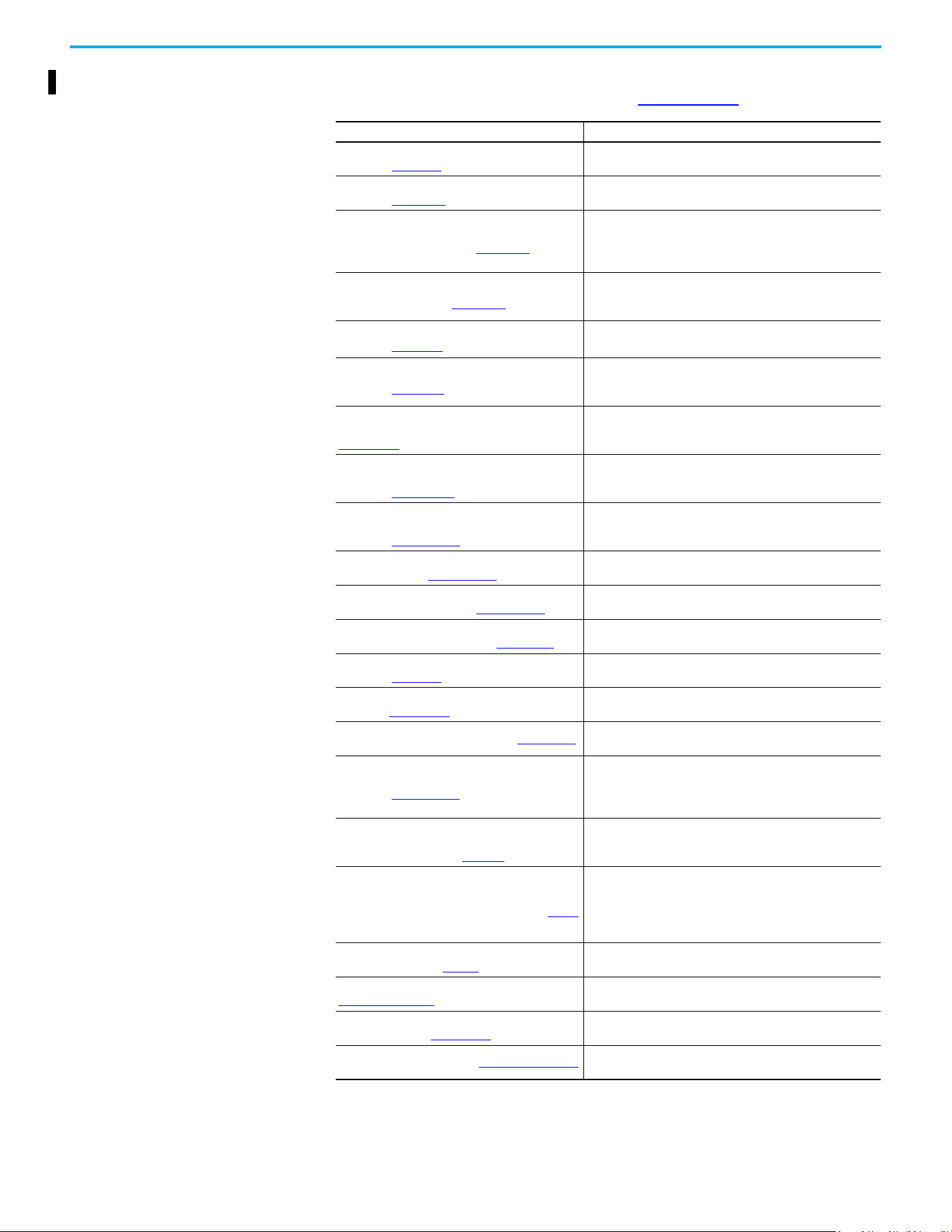
About This Publication . . . . . . . . . . . . . . . . . . . . . . . . . . . . . . . . . . . . . . . . . . . . . . . . . . . . . . . 7
Download Firmware, AOP, EDS, and Other Files . . . . . . . . . . . . . . . . . . . . . . . . . . . . . . . . . . . 7
Summary of Changes. . . . . . . . . . . . . . . . . . . . . . . . . . . . . . . . . . . . . . . . . . . . . . . . . . . . . . . . 7
Who Should Use this Manual . . . . . . . . . . . . . . . . . . . . . . . . . . . . . . . . . . . . . . . . . . . . . . . . . . 7
Additional Resources . . . . . . . . . . . . . . . . . . . . . . . . . . . . . . . . . . . . . . . . . . . . . . . . . . . . . . . . 8
Manual Conventions. . . . . . . . . . . . . . . . . . . . . . . . . . . . . . . . . . . . . . . . . . . . . . . . . . . . . . . . . 9
Drive Frame Sizes. . . . . . . . . . . . . . . . . . . . . . . . . . . . . . . . . . . . . . . . . . . . . . . . . . . . . . . . . . . 9
General Precautions. . . . . . . . . . . . . . . . . . . . . . . . . . . . . . . . . . . . . . . . . . . . . . . . . . . . . . . . 10
Catalog Number Explanation . . . . . . . . . . . . . . . . . . . . . . . . . . . . . . . . . . . . . . . . . . . . . 11
Chapter 1
Installation/Wiring Mounting Considerations . . . . . . . . . . . . . . . . . . . . . . . . . . . . . . . . . . . . . . . . . . . . . . . . . . . . 13
Minimum Mounting Clearances . . . . . . . . . . . . . . . . . . . . . . . . . . . . . . . . . . . . . . . . . . . 13
Ambient Operating Temperatures . . . . . . . . . . . . . . . . . . . . . . . . . . . . . . . . . . . . . . . . . 15
Current Derating Curves. . . . . . . . . . . . . . . . . . . . . . . . . . . . . . . . . . . . . . . . . . . . . . . . . 15
Debris Protection . . . . . . . . . . . . . . . . . . . . . . . . . . . . . . . . . . . . . . . . . . . . . . . . . . . . . . 16
Storage . . . . . . . . . . . . . . . . . . . . . . . . . . . . . . . . . . . . . . . . . . . . . . . . . . . . . . . . . . . . . . 16
AC Supply Source Considerations . . . . . . . . . . . . . . . . . . . . . . . . . . . . . . . . . . . . . . . . . . . . . 16
Ungrounded Distribution Systems. . . . . . . . . . . . . . . . . . . . . . . . . . . . . . . . . . . . . . . . . 16
Input Power Conditioning. . . . . . . . . . . . . . . . . . . . . . . . . . . . . . . . . . . . . . . . . . . . . . . . 17
General Grounding Requirements . . . . . . . . . . . . . . . . . . . . . . . . . . . . . . . . . . . . . . . . . . . . . 18
Ground Fault Monitoring. . . . . . . . . . . . . . . . . . . . . . . . . . . . . . . . . . . . . . . . . . . . . . . . . 18
Safety Ground - (PE). . . . . . . . . . . . . . . . . . . . . . . . . . . . . . . . . . . . . . . . . . . . . . . . . . . . 18
Motor Ground . . . . . . . . . . . . . . . . . . . . . . . . . . . . . . . . . . . . . . . . . . . . . . . . . . . . . . . . . 18
Shield Termination - SHLD . . . . . . . . . . . . . . . . . . . . . . . . . . . . . . . . . . . . . . . . . . . . . . . 18
RFI Filter Grounding . . . . . . . . . . . . . . . . . . . . . . . . . . . . . . . . . . . . . . . . . . . . . . . . . . . . 18
Fuses and Circuit Breakers . . . . . . . . . . . . . . . . . . . . . . . . . . . . . . . . . . . . . . . . . . . . . . . . . . 19
Fusing . . . . . . . . . . . . . . . . . . . . . . . . . . . . . . . . . . . . . . . . . . . . . . . . . . . . . . . . . . . . . . . 19
Circuit Breakers . . . . . . . . . . . . . . . . . . . . . . . . . . . . . . . . . . . . . . . . . . . . . . . . . . . . . . . 19
Fuses and Circuit Breakers for PowerFlex 527 . . . . . . . . . . . . . . . . . . . . . . . . . . . . . . . 19
Power and Control Module. . . . . . . . . . . . . . . . . . . . . . . . . . . . . . . . . . . . . . . . . . . . . . . . . . . 25
Control Module Cover. . . . . . . . . . . . . . . . . . . . . . . . . . . . . . . . . . . . . . . . . . . . . . . . . . . . . . . 28
Power Module Terminal Guard. . . . . . . . . . . . . . . . . . . . . . . . . . . . . . . . . . . . . . . . . . . . . . . . 28
Power Wiring . . . . . . . . . . . . . . . . . . . . . . . . . . . . . . . . . . . . . . . . . . . . . . . . . . . . . . . . . . . . . 29
Motor Cable Types Acceptable for 100…600 Volt Installations. . . . . . . . . . . . . . . . . . . 29
Reflected Wave Protection. . . . . . . . . . . . . . . . . . . . . . . . . . . . . . . . . . . . . . . . . . . . . . . 31
Output Disconnect . . . . . . . . . . . . . . . . . . . . . . . . . . . . . . . . . . . . . . . . . . . . . . . . . . . . . 31
Power Terminal Block . . . . . . . . . . . . . . . . . . . . . . . . . . . . . . . . . . . . . . . . . . . . . . . . . . . . . . 31
I/O Wiring . . . . . . . . . . . . . . . . . . . . . . . . . . . . . . . . . . . . . . . . . . . . . . . . . . . . . . . . . . . . . . . . 32
Motor Start/Stop Precautions. . . . . . . . . . . . . . . . . . . . . . . . . . . . . . . . . . . . . . . . . . . . . 32
Signal and Control Wire Types. . . . . . . . . . . . . . . . . . . . . . . . . . . . . . . . . . . . . . . . . . . . 32
Maximum Control Wire Recommendations . . . . . . . . . . . . . . . . . . . . . . . . . . . . . . . . . . 33
Control I/O Terminal Block. . . . . . . . . . . . . . . . . . . . . . . . . . . . . . . . . . . . . . . . . . . . . . . . . . . 33
PowerFlex 527 Control I/O Removable Terminal Block . . . . . . . . . . . . . . . . . . . . . . . . . 34
CE Conformity. . . . . . . . . . . . . . . . . . . . . . . . . . . . . . . . . . . . . . . . . . . . . . . . . . . . . . . . . . . . . 36

4 Rockwell Automation Publication 520-UM002E-EN-E - September 2024
Table of Contents
Low Voltage Directive (2014/35/EU). . . . . . . . . . . . . . . . . . . . . . . . . . . . . . . . . . . . . . . . 36
EMC Directive (2014/30/EU) . . . . . . . . . . . . . . . . . . . . . . . . . . . . . . . . . . . . . . . . . . . . . . 36
Machinery Directive (2006/42/EC). . . . . . . . . . . . . . . . . . . . . . . . . . . . . . . . . . . . . . . . . 36
ATEX Directive (2014/34/EU) . . . . . . . . . . . . . . . . . . . . . . . . . . . . . . . . . . . . . . . . . . . . . 37
UKCA Conformity . . . . . . . . . . . . . . . . . . . . . . . . . . . . . . . . . . . . . . . . . . . . . . . . . . . . . . . . . . 37
Electrical Equipment (Safety) Regulations (2016 No. 1101) . . . . . . . . . . . . . . . . . . . . . . 37
Electromagnetic Compatibility Regulations (2016 No. 1091) . . . . . . . . . . . . . . . . . . . . . 37
Supply of Machinery (Safety) Regulations (2008 No. 1597). . . . . . . . . . . . . . . . . . . . . . 37
Equipment and Protective Systems Intended for Use in Potentially Explosive
Atmospheres Regulations (2016 No. 1107) . . . . . . . . . . . . . . . . . . . . . . . . . . . . . . . . . . . 37
General Considerations . . . . . . . . . . . . . . . . . . . . . . . . . . . . . . . . . . . . . . . . . . . . . . . . . 37
Chapter 2
Start Up Prepare for Drive Startup. . . . . . . . . . . . . . . . . . . . . . . . . . . . . . . . . . . . . . . . . . . . . . . . . . . . 43
Drive Startup Task List. . . . . . . . . . . . . . . . . . . . . . . . . . . . . . . . . . . . . . . . . . . . . . . . . . 43
Start, Stop, Direction, and Speed Control. . . . . . . . . . . . . . . . . . . . . . . . . . . . . . . . . . . . 44
Understanding the PowerFlex 527 Display and Indicators. . . . . . . . . . . . . . . . . . . . . . . . . . 44
Startup Sequence. . . . . . . . . . . . . . . . . . . . . . . . . . . . . . . . . . . . . . . . . . . . . . . . . . . . . . 45
Device and Axis States. . . . . . . . . . . . . . . . . . . . . . . . . . . . . . . . . . . . . . . . . . . . . . . . . . 45
Information Display . . . . . . . . . . . . . . . . . . . . . . . . . . . . . . . . . . . . . . . . . . . . . . . . . . . . 46
Network Configuration . . . . . . . . . . . . . . . . . . . . . . . . . . . . . . . . . . . . . . . . . . . . . . . . . . 46
Real-time Information Display . . . . . . . . . . . . . . . . . . . . . . . . . . . . . . . . . . . . . . . . . . . . 48
Drive Programming Tools . . . . . . . . . . . . . . . . . . . . . . . . . . . . . . . . . . . . . . . . . . . . . . . . . . . 48
Language Support . . . . . . . . . . . . . . . . . . . . . . . . . . . . . . . . . . . . . . . . . . . . . . . . . . . . . . . . . 48
Using the Ethernet Port . . . . . . . . . . . . . . . . . . . . . . . . . . . . . . . . . . . . . . . . . . . . . . . . . . . . . 49
Chapter 3
Configuring the PowerFlex 527
Drive with Integrated Motion
Configure the Drive . . . . . . . . . . . . . . . . . . . . . . . . . . . . . . . . . . . . . . . . . . . . . . . . . . . . . . . . 51
Set the Network Configuration. . . . . . . . . . . . . . . . . . . . . . . . . . . . . . . . . . . . . . . . . . . . 51
Configure the Logix Designer Application Project . . . . . . . . . . . . . . . . . . . . . . . . . . . . . . . . 51
Configure the Logix 5000 Controller . . . . . . . . . . . . . . . . . . . . . . . . . . . . . . . . . . . . . . . 52
Add a PowerFlex 527 Drive . . . . . . . . . . . . . . . . . . . . . . . . . . . . . . . . . . . . . . . . . . . . . . . . . . 56
Configure the PowerFlex 527 Drive . . . . . . . . . . . . . . . . . . . . . . . . . . . . . . . . . . . . . . . . . . . . 58
Configure Drive with Hardwired Safety Connections . . . . . . . . . . . . . . . . . . . . . . . . . . 58
Configure Drive with Integrated Safety Connections . . . . . . . . . . . . . . . . . . . . . . . . . . 59
Continue Drive Configuration . . . . . . . . . . . . . . . . . . . . . . . . . . . . . . . . . . . . . . . . . . . . . 61
Configure the Motion Group . . . . . . . . . . . . . . . . . . . . . . . . . . . . . . . . . . . . . . . . . . . . . . 64
Configure Axis Properties. . . . . . . . . . . . . . . . . . . . . . . . . . . . . . . . . . . . . . . . . . . . . . . . 65
Download the Program. . . . . . . . . . . . . . . . . . . . . . . . . . . . . . . . . . . . . . . . . . . . . . . . . . 75
Apply Power to the PowerFlex 527 Drive . . . . . . . . . . . . . . . . . . . . . . . . . . . . . . . . . . . . . . . 75
Test and Tune the Axes – Velocity and Position Control Modes. . . . . . . . . . . . . . . . . . . . . . 76
Test the Axes . . . . . . . . . . . . . . . . . . . . . . . . . . . . . . . . . . . . . . . . . . . . . . . . . . . . . . . . . 76
Tune the Axes. . . . . . . . . . . . . . . . . . . . . . . . . . . . . . . . . . . . . . . . . . . . . . . . . . . . . . . . . 78
Chapter 4
PowerFlex 527 Integrated Safe
Torque Off
Certification . . . . . . . . . . . . . . . . . . . . . . . . . . . . . . . . . . . . . . . . . . . . . . . . . . . . . . . . . . . . . . 81
Important Safety Considerations. . . . . . . . . . . . . . . . . . . . . . . . . . . . . . . . . . . . . . . . . . 81
Category 3 Requirements According to ISO 13849 . . . . . . . . . . . . . . . . . . . . . . . . . . . . 81

Rockwell Automation Publication 520-UM002E-EN-E - September 2024 5
Table of Contents
Stop Category Definition. . . . . . . . . . . . . . . . . . . . . . . . . . . . . . . . . . . . . . . . . . . . . . . . . 81
Performance Level (PL) and Safety Integrity Level (SIL) . . . . . . . . . . . . . . . . . . . . . . . 81
Description of Operation . . . . . . . . . . . . . . . . . . . . . . . . . . . . . . . . . . . . . . . . . . . . . . . . . . . . 82
Probability of Dangerous Failure Per Hour (PFH) . . . . . . . . . . . . . . . . . . . . . . . . . . . . . . . . . 82
PFH Data . . . . . . . . . . . . . . . . . . . . . . . . . . . . . . . . . . . . . . . . . . . . . . . . . . . . . . . . . . . . . 82
Safe Torque Off (STO) Feature. . . . . . . . . . . . . . . . . . . . . . . . . . . . . . . . . . . . . . . . . . . . . . . . 82
Safe Torque Off Feature Bypass . . . . . . . . . . . . . . . . . . . . . . . . . . . . . . . . . . . . . . . . . . 83
As-Shipped Safety Configuration. . . . . . . . . . . . . . . . . . . . . . . . . . . . . . . . . . . . . . . . . . 83
Out-of-Box (OOB) Safety State. . . . . . . . . . . . . . . . . . . . . . . . . . . . . . . . . . . . . . . . . . . . . . . . 83
Recognizing the Out-of-Box State . . . . . . . . . . . . . . . . . . . . . . . . . . . . . . . . . . . . . . . . . 83
Restoring the Drive to the Out-of-Box State . . . . . . . . . . . . . . . . . . . . . . . . . . . . . . . . . 84
Safe Torque Off Status. . . . . . . . . . . . . . . . . . . . . . . . . . . . . . . . . . . . . . . . . . . . . . . . . . . . . . 85
Axis Tags. . . . . . . . . . . . . . . . . . . . . . . . . . . . . . . . . . . . . . . . . . . . . . . . . . . . . . . . . . . . . 85
Explicit Messages. . . . . . . . . . . . . . . . . . . . . . . . . . . . . . . . . . . . . . . . . . . . . . . . . . . . . . . . . . 86
Safety Supervisor State . . . . . . . . . . . . . . . . . . . . . . . . . . . . . . . . . . . . . . . . . . . . . . . . . 86
Propose TUNID Blocked . . . . . . . . . . . . . . . . . . . . . . . . . . . . . . . . . . . . . . . . . . . . . . . . . 86
Safe Torque Off Mode. . . . . . . . . . . . . . . . . . . . . . . . . . . . . . . . . . . . . . . . . . . . . . . . . . . 87
Safe Torque Off Faults . . . . . . . . . . . . . . . . . . . . . . . . . . . . . . . . . . . . . . . . . . . . . . . . . . 87
Chapter 5
Hardwired Control of Safe
Torque Off
Description of Operation . . . . . . . . . . . . . . . . . . . . . . . . . . . . . . . . . . . . . . . . . . . . . . . . . . . . 89
Selection of Hardwired Safe Torque Off . . . . . . . . . . . . . . . . . . . . . . . . . . . . . . . . . . . . 89
Operation of Hardwired Safe Torque Off. . . . . . . . . . . . . . . . . . . . . . . . . . . . . . . . . . . . 89
Troubleshoot the Safe Torque Off Function . . . . . . . . . . . . . . . . . . . . . . . . . . . . . . . . . 90
Safe Torque Off Connector Data . . . . . . . . . . . . . . . . . . . . . . . . . . . . . . . . . . . . . . . . . . . . . . 92
Wire the Safe Torque Off Circuit . . . . . . . . . . . . . . . . . . . . . . . . . . . . . . . . . . . . . . . . . . . . . . 92
Safe Torque Off Wiring Requirements. . . . . . . . . . . . . . . . . . . . . . . . . . . . . . . . . . . . . . 92
Safe Torque Off Specifications . . . . . . . . . . . . . . . . . . . . . . . . . . . . . . . . . . . . . . . . . . . . . . . 93
Chapter 6
Network Control of Safe Torque
Off
Compatible Safety Controllers . . . . . . . . . . . . . . . . . . . . . . . . . . . . . . . . . . . . . . . . . . . . 95
Selection of Network Safe Torque Off . . . . . . . . . . . . . . . . . . . . . . . . . . . . . . . . . . . . . . 95
Safety Application Requirements . . . . . . . . . . . . . . . . . . . . . . . . . . . . . . . . . . . . . . . . . 95
Network Safe Torque Off Specifications . . . . . . . . . . . . . . . . . . . . . . . . . . . . . . . . . . . . 96
Safe Torque Off Assembly Tags. . . . . . . . . . . . . . . . . . . . . . . . . . . . . . . . . . . . . . . . . . . 96
STO Fault Reset. . . . . . . . . . . . . . . . . . . . . . . . . . . . . . . . . . . . . . . . . . . . . . . . . . . . . . . . 97
Troubleshoot Network Safe Torque Off . . . . . . . . . . . . . . . . . . . . . . . . . . . . . . . . . . . . . 98
Understanding Integrated Safety Drive Replacement . . . . . . . . . . . . . . . . . . . . . . . . . . . . . 99
Replacing an Integrated Safety Drive in a GuardLogix System . . . . . . . . . . . . . . . . . . . . . . 99
Replacement with “Configure Only When No Safety Signature Exists” Enabled . . . . . 99
Replacement with “Configure Always” Enabled . . . . . . . . . . . . . . . . . . . . . . . . . . . . . 104
Motion Direct Commands in Motion Control Systems . . . . . . . . . . . . . . . . . . . . . . . . . . . . . 105
Understanding STO Bypass When Using Motion Direct Commands . . . . . . . . . . . . . . 105
Logix Designer Application Warning Messages. . . . . . . . . . . . . . . . . . . . . . . . . . . . . . 106
Torque Permitted in a Multi-workstation Environment. . . . . . . . . . . . . . . . . . . . . . . . 108
Warning Icon and Text in Axis Properties . . . . . . . . . . . . . . . . . . . . . . . . . . . . . . . . . . 108
Functional Safety Considerations . . . . . . . . . . . . . . . . . . . . . . . . . . . . . . . . . . . . . . . . . . . . 109

6 Rockwell Automation Publication 520-UM002E-EN-E - September 2024
Table of Contents
Chapter 7
Troubleshooting Safety Precautions. . . . . . . . . . . . . . . . . . . . . . . . . . . . . . . . . . . . . . . . . . . . . . . . . . . . . . . . . 111
Interpret Status Indicators. . . . . . . . . . . . . . . . . . . . . . . . . . . . . . . . . . . . . . . . . . . . . . . . . . . 111
Display Interface. . . . . . . . . . . . . . . . . . . . . . . . . . . . . . . . . . . . . . . . . . . . . . . . . . . . . . . 111
Fault Codes. . . . . . . . . . . . . . . . . . . . . . . . . . . . . . . . . . . . . . . . . . . . . . . . . . . . . . . . . . . 111
PowerFlex 527 Drive Status Indicators . . . . . . . . . . . . . . . . . . . . . . . . . . . . . . . . . . . . 116
General Troubleshooting . . . . . . . . . . . . . . . . . . . . . . . . . . . . . . . . . . . . . . . . . . . . . . . . . . . 117
Logix 5000 Controller and Drive Behavior . . . . . . . . . . . . . . . . . . . . . . . . . . . . . . . . . . . . . 119
PowerFlex 527 Drive Exception Behavior . . . . . . . . . . . . . . . . . . . . . . . . . . . . . . . . . . 119
Appendix A
Supplemental Drive Information Certifications . . . . . . . . . . . . . . . . . . . . . . . . . . . . . . . . . . . . . . . . . . . . . . . . . . . . . . . . . . . . 123
Environmental Specifications . . . . . . . . . . . . . . . . . . . . . . . . . . . . . . . . . . . . . . . . . . . . . . . 124
Technical Specifications . . . . . . . . . . . . . . . . . . . . . . . . . . . . . . . . . . . . . . . . . . . . . . . . . . . 125
Power Specifications . . . . . . . . . . . . . . . . . . . . . . . . . . . . . . . . . . . . . . . . . . . . . . . . . . . . . . 127
Appendix B
Accessories and Dimensions Product Selection. . . . . . . . . . . . . . . . . . . . . . . . . . . . . . . . . . . . . . . . . . . . . . . . . . . . . . . . . 131
Product Dimensions. . . . . . . . . . . . . . . . . . . . . . . . . . . . . . . . . . . . . . . . . . . . . . . . . . . . . . . 139
Replacing the PowerFlex 527 Control Module Internal Fan. . . . . . . . . . . . . . . . . . . . . 151
Appendix C
Out-of-Box Configuration Recommended Out-of-Box Settings . . . . . . . . . . . . . . . . . . . . . . . . . . . . . . . . . . . . . . . . . . 153
Setting the ACO/AVO Attribute . . . . . . . . . . . . . . . . . . . . . . . . . . . . . . . . . . . . . . . . . . . . . . . 156
Appendix D
Encoder Option Card Usage Installing the Encoder Option Card . . . . . . . . . . . . . . . . . . . . . . . . . . . . . . . . . . . . . . . . . . . 157
Removing the Encoder Option Card . . . . . . . . . . . . . . . . . . . . . . . . . . . . . . . . . . . . . . . . . . 158
Encoder Option Card Usage. . . . . . . . . . . . . . . . . . . . . . . . . . . . . . . . . . . . . . . . . . . . . . . . . 158
Encoder Interface. . . . . . . . . . . . . . . . . . . . . . . . . . . . . . . . . . . . . . . . . . . . . . . . . . . . . 159
HTL/TTL DIP Switches. . . . . . . . . . . . . . . . . . . . . . . . . . . . . . . . . . . . . . . . . . . . . . . . . . 160
Wiring Notes . . . . . . . . . . . . . . . . . . . . . . . . . . . . . . . . . . . . . . . . . . . . . . . . . . . . . . . . . . . . . 160
Index . . . . . . . . . . . . . . . . . . . . . . . . . . . . . . . . . . . . . . . . . . . . . . . . . . . . . . . . . . . . . . . . . . 161

Rockwell Automation Publication 520-UM002E-EN-E - September 2024 7
Preface
About This Publication The purpose of this manual is to provide you with the basic information that is needed to install,
startup, and troubleshoot the PowerFlex® 527 Adjustable Frequency AC Drive.
Rockwell Automation recognizes that some of the terms that are currently used in our industry and
in this publication are not in alignment with the movement toward inclusive language in technology.
We are proactively collaborating with industry peers to find alternatives to such terms and making
changes to our products and content. Please excuse the use of such terms in our content while we
implement these changes.
Download Firmware, AOP,
EDS, and Other Files
Download firmware, associated files (such as AOP, EDS, and DTM), and access product release
notes from the Product Compatibility and Download Center at rok.auto/pcdc.
Summary of Changes This publication contains the following new or updated information. This list includes substantive
updates only and is not intended to reflect all changes.
Who Should Use this Manual This manual is intended for qualified personnel. You must be able to program and operate
Adjustable Frequency AC Drive devices. In addition, you must have a working knowledge and
understanding of ControlLogix®/Studio 5000® and CIP Motion™.
If you do not have a basic understanding of the PowerFlex 527 drives, contact your local Rockwell
Automation sales representative for information on available training courses.
Topic Page
Updated template Throughout
Updated Additional Resources 8
Updated section Circuit Breakers 19
Updated Fuses and Circuit Breakers for PowerFlex 527 19…24
Updated Installation Requirements Related to EN 61800-5-1 and the Low Voltage Directive/UK
LV Regulations
38
Updated Certifications 123
Updated Dynamic Brake Resistors 133
8 Rockwell Automation Publication 520-UM002E-EN-E - September 2024
Preface
Additional Resources These documents contain additional information concerning related products from Rockwell
Automation. You can view or download publications at rok.auto/literature
.
Resource Description
PowerFlex 527 AC Drive Specifications Technical Data,
publication 520-TD002
Describes how to configure, use, and troubleshoot
PowerFlex 520-series drives.
GuardLogix 5570 Controllers User Manual,
publication 1756-UM022
Describes how to configure and use the GuardLogix® 5570
controller in a Studio 5000 Logix Designer® application.
GuardLogix 5570 and Compact GuardLogix 5370
Reference Manual, publication 1756-RM099
Contains detailed requirements for achieving and maintaining
SIL 3/PLe with the GuardLogix 5570 and Compact GuardLogix
5370 controller system, using the Studio 5000 Logix Designer
application.
ControlLogix 5580 and GuardLogix 5580 Controllers
User Manual, publication 1756-UM543
Describes how to configure and use the ControlLogix® 5580 and
GuardLogix 5580 controllers in a Studio 5000 Logix Designer
application.
CompactLogix 5370 Controllers User Manual,
publication 1769-UM021
Describes how to configure and use the CompactLogix® 5370
controller in a Studio 5000 Logix Designer application.
Compact GuardLogix 5370 Controllers User Manual,
publication 1769-UM022
Describes how to configure and use the Compact
GuardLogix 5370 controller in a Studio 5000 Logix Designer
application.
Wiring and Grounding for Pulse Width Modulated
(PWM) AC Drives Installation Instructions, publication
DRIVES-IN001
Provides basic information to install, protect, wire, and ground
pulse-width modulated (PWM) AC drives
Preventive Maintenance Checklist of Industrial Control
and Drive System Equipment Service Bulletin,
publication DRIVES-TD001
Provides a checklist as a guide in performing preventive
maintenance.
Integrated Motion on the EtherNet/IP Network:
Configuration and Startup User Manual,
publication MOTION-UM003
Details how to configure an Integrated Motion on EtherNet/IP™
networks application system.
Logix 5000 Controllers Motion Instructions Reference
Manual, publication MOTION-RM002
Provides programmers with details about the motion
instructions that are available for a Logix 5000® controller.
Integrated Motion on the EtherNet/IP Network
Reference Manual, publication MOTION-RM003
Detailed information on axis control modes and attributes for
Integrated Motion on EtherNet/IP networks.
PowerFlex Dynamic Braking Resistor Calculator
Application Technique, publication PFLEX-AT001
Provides information on dynamic braking and how to determine
dynamic brake requirements for your drive.
Guarding Against Electrostatic Damage,
publication 8000-4.5.2
Provides information on how to guard against the effects of ESD.
EtherNet/IP Network Devices User Manual,
publication ENET-UM006
Describes how to configure and use EtherNet/IP devices to
communicate on the EtherNet/IP network.
Ethernet Reference Manual, publication ENET-RM002
Describes basic Ethernet concepts, infrastructure components,
and infrastructure features.
System Security Design Guidelines Reference Manual,
publication SECURE-RM001
Provides guidance on how to conduct security assessments,
implement Rockwell Automation products in a secure system,
harden the control system, manage user access, and dispose of
equipment.
Industrial Components Preventive Maintenance,
Enclosures, and Contact Ratings Specifications
Technical Data, publication IC-TD002
Provides a quick reference tool for Allen-Bradley® industrial
automation controls and assemblies.
Safety Guidelines for the Application, Installation, and
Maintenance of Solid-state Control, publication SGI-1.1
Designed to harmonize with NEMA Standards Publication No.
ICS 1.1-1987 and provides general guidelines for the application,
installation, and maintenance of solid-state control in the form
of individual devices or packaged assemblies incorporating
solid-state components.
Industrial Automation Wiring and Grounding
Guidelines, publication 1770-4.1
Provides general guidelines for installing a Rockwell Automation
industrial system.
Product Selection and Configuration tools,
rok.auto/systemtools
Helps configure complete, valid catalog numbers and build
complete quotes based on detailed product information.
Rockwell Automation Global Short-circuit Current
Ratings (SCCR) Tool, rok.auto/sccr
Provides coordinated high-fault branch circuit solutions for
motor starters, soft starters, and component drives.
Product Certifications website, rok.auto/certifications
Provides declarations of conformity, certificates, and other
certification details.

Rockwell Automation Publication 520-UM002E-EN-E - September 2024 9
Preface
Manual Conventions • In this manual we refer to PowerFlex 527 Adjustable Frequency AC Drive as: drive,
PowerFlex 527, PowerFlex 527 drive, or PowerFlex 527 AC drive.
• Specific drives within the PowerFlex 520-series may be referred to as:
– PowerFlex 523, PowerFlex 523 drive, or PowerFlex 523 AC drive.
– PowerFlex 525, PowerFlex 525 drive, or PowerFlex 525 AC drive.
– PowerFlex 527, PowerFlex 527 drive, or PowerFlex 527 AC drive.
• The following words are used throughout the manual to describe an action:
• The Studio 5000 Automation Engineering and Design Environment® (formerly RSLogix
5000®) combines engineering and design elements into one standard framework that
enables optimized productivity and reduced time to commission. As part of the Studio
5000® environment, Studio 5000 Logix Designer application is the tool that is used to
program Logix programmable automation controllers for process, batch, discrete, drives,
safety, and motion-based systems. The Studio 5000 environment is the foundation for
system engineering design tools and capabilities — it is the one tool for engineers to design
and develop all elements of their control system.
These conventions are used throughout this manual:
• Bulleted lists such as this one provide information, not procedural steps.
• Numbered lists provide steps or hierarchical information.
Drive Frame Sizes The PowerFlex 527 AC drive belongs to the new generation of PowerFlex 520-series drives, which
also consist of PowerFlex 523 and PowerFlex 525 drives.
Similar PowerFlex 520-series drive sizes are grouped into frame sizes to simplify spare parts
ordering, dimensioning, and so on. A cross-reference of drive catalog numbers and their respective
frame sizes is provided in Appendix B on page 131
.
Words Meaning
Can Possible, able to do something
Cannot Not possible, not able to do something
May Permitted, allowed
Must Unavoidable, you must do this
Shall Required and necessary
Should Recommended
Should Not Not recommended

10 Rockwell Automation Publication 520-UM002E-EN-E - September 2024
Preface
General Precautions
ATTENTION: The drive contains high-voltage capacitors, which take time to
discharge after removal of mains supply. Before working on drive, verify
isolation of mains supply from line inputs [R, S, T (L1, L2, L3)]. Wait three
minutes for capacitors to discharge to safe voltage levels (DC Bus voltage is
less than 50V DC). Failure to do so may result in personal injury or death.
Darkened display LEDs is not an indication that capacitors have discharged to
safe voltage levels.
ATTENTION: Only qualified personnel familiar with adjustable frequency AC
drives and associated machinery should plan or implement the installation,
start-up and subsequent maintenance of the system. Failure to comply may
result in personal injury and/or equipment damage.
ATTENTION: This drive contains ESD (Electrostatic Discharge) sensitive parts
and assemblies. Static control precautions are required when installing, testing,
servicing, or repairing this assembly. Component damage may result if ESD
control procedures are not followed. If you are not familiar with static control
procedures, reference publication 8000-4.5.2
, “Guarding Against Electrostatic
Damage” or any other applicable ESD protection handbook.
ATTENTION: An incorrectly applied or installed drive can result in component
damage or a reduction in product life. Wiring or application errors, such as
undersizing the motor, incorrect or inadequate AC supply, or excessive ambient
temperatures may result in malfunction of the system.
ATTENTION: The bus regulator function is extremely useful for preventing
nuisance overvoltage faults resulting from aggressive decelerations,
overhauling loads, and eccentric loads. However, it can also cause either of the
following two conditions to occur.
1. Fast positive changes in input voltage or imbalanced input voltages can cause
uncommanded positive speed changes.
2. Actual deceleration times can be longer than commanded deceleration times.
However, a “Decel Override” fault is generated if the drive remains in this state
for one minute. If this condition is unacceptable, the bus regulator must be
disabled by setting the Bus Regulator Action in the Logix Designer application.
In addition, installing a properly sized dynamic brake resistor provides equal or
better performance in most cases. See Dynamic Brake Resistors on page 133
to
select an appropriate resistor for your drive rating.
ATTENTION: Risk of injury or equipment damage exists. Drive does not contain
user-serviceable components. Do not disassemble drive chassis.
Rockwell Automation Publication 520-UM002E-EN-E - September 2024 11
Preface
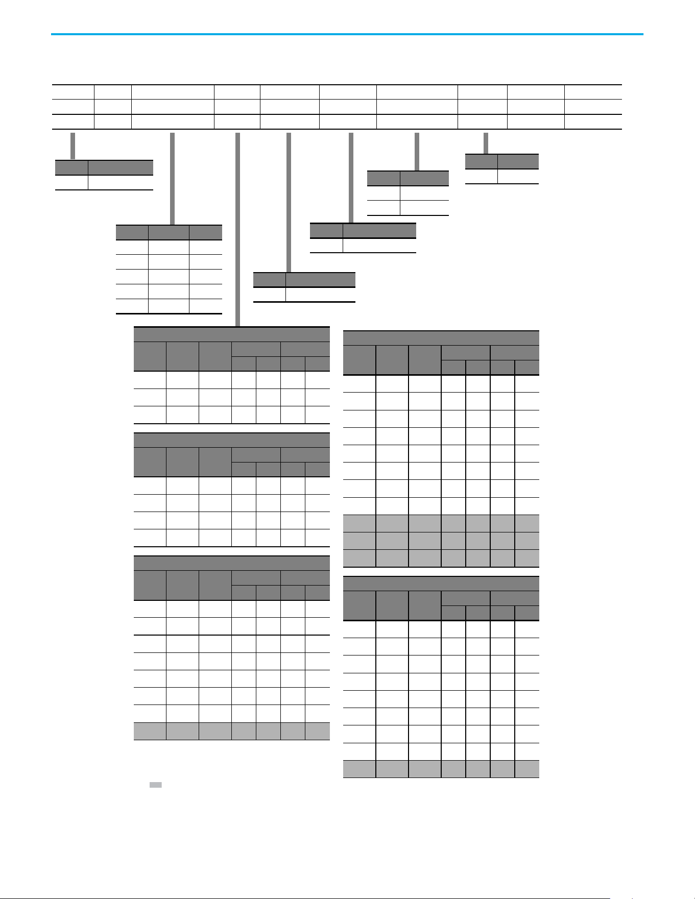
Catalog Number Explanation
Code Type
25C PowerFlex 527
1-3 4 5 6-8 9 10 11 12 13 14
25C – B 2P3 N 1 1 4 – –
Drive Dash Voltage Rating Rating Enclosure Reserved Emission Class Reserved Dash Dash
Output Current @ 1 Phase, 100...120V Input
Code Amps Frame
ND HD
HP kW HP kW
2P5
(1)
2.5 A 0.5 0.4 0.5 0.4
4P8
(1)
4.8 B 1.0 0.75 1.0 0.75
6P0
(1)
6.0 B 1.5 1.1 1.5 1.1
Output Current @ 1 Phase, 200...240V Input
Code Amps Frame
ND HD
HP kW HP kW
2P5
(1)
2.5 A 0.5 0.4 0.5 0.4
4P8
(1)
4.8 A 1.0 0.75 1.0 0.75
8P0
(1)
8.0 B 2.0 1.5 2.0 1.5
011
(1)
11.0 B 3.0 2.2 3.0 2.2
Output Current @ 3Phase, 200...240V Input
Code Amps Frame
ND HD
HP kW HP kW
2P5
(1)
2.5 A 0.5 0.4 0.5 0.4
5P0
(1)
5.0 A 1.0 0.75 1.0 0.75
8P0
(1)
8.0 A 2.0 1.5 2.0 1.5
011
(1)
11.0 A 3.0 2.2 3.0 2.2
017
(1)
17.5 B 5.0 4.0 5.0 4.0
024
(1)
24.0 C 7.5 5.5 7.5 5.5
032
(1)
32.2 D 10.0 7.5 10.0 7.5
048
(2)
48.3 E 15.0 11.0 10.0 7.5
Output Current @ 3 Phase, 380...480V Input
Code Amps Frame
ND HD
HP kW HP kW
1P4
(1)
1.4 A 0.5 0.4 0.5 0.4
2P3
(1)
2.3 A 1.0 0.75 1.0 0.75
4P0
(1)
4.0 A 2.0 1.5 2.0 1.5
6P0
(1)
6.0 A 3.0 2.2 3.0 2.2
010
(1)
10.5 B 5.0 4.0 5.0 4.0
013
(1)
13.0 C 7.5 5.5 7.5 5.5
017
(1)
17.0 C 10.0 7.5 10.0 7.5
024
(1)
24.0 D 15.0 11.0 15.0 11.0
030
(2)
30.0 D 20.0 15.0 15.0 11.0
037
(2)
37.0 E 25.0 18.5 20.0 15.0
043
(2)
43.0 E 30.0 22.0 25.0 18.5
Output Current @ 3 Phase, 525...600V Input
Code Amps Frame
ND HD
HP kW HP kW
0P9
(1)
0.9 A 0.5 0.4 0.5 0.4
1P7
(1)
1.7 A 1.0 0.75 1.0 0.75
3P0
(1)
3.0 A 2.0 1.5 2.0 1.5
4P2
(1)
4.2 A 3.0 2.2 3.0 2.2
6P6
(1)
6.6 B 5.0 4.0 5.0 4.0
9P9
(1)
9.9 C 7.5 5.5 7.5 5.5
012
(1)
12.0 C 10.0 7.5 10.0 7.5
019
(1)
19.0 D 15.0 11.0 15.0 11.0
022
(2)
22.0 D 20.0 15.0 15.0 11.0
Code Voltage Phase
V120V AC1
A240V AC1
B240V AC3
D480V AC3
E600V AC3
Code Enclosure
NIP20 NEMA / Open
Code Interface Module
1Standard
Code EMC Filter
0No Filter
1 Filter
Code Braking
4Standard
(1) 150% Overload capability for up to 60 s, 180% for up to 3 s.
(2) 110% Overload capability for up to 60 s, 150% for up to 3 s.

12 Rockwell Automation Publication 520-UM002E-EN-E - September 2024
Preface
Notes:
Rockwell Automation Publication 520-UM002E-EN-E - September 2024 13
Chapter
Chapter 1
Installation/Wiring
This chapter provides information on mounting and wiring the PowerFlex 527 drives.
Most startup difficulties are the result of incorrect wiring. Every precaution must be taken to verify
that the wiring is done as instructed. All items must be read and understood before the actual
installation begins.
Mounting Considerations • Mount the drive upright on a flat, vertical, and level surface.
• Protect the cooling fan by avoiding dust or metallic particles.
• Do not expose to a corrosive atmosphere.
• Protect from moisture and direct sunlight.
Minimum Mounting Clearances
For mounting dimensions, see Product Dimensions on page 139.
ATTENTION: The following information is merely a guide for proper installation.
Rockwell Automation cannot assume responsibility for the compliance or the
noncompliance to any code, national, local or otherwise for the proper
installation of this drive or associated equipment. A hazard of personal injury
and/or equipment damage exists if codes are ignored during installation.
Frame Screw Size Screw Torque
A M5 (#10…24) 1.56…1.96 N•m (14…17 lb•in)
B M5 (#10…24) 1.56…1.96 N•m (14…17 lb•in)
C M5 (#10…24) 1.56…1.96 N•m (14…17 lb•in)
D M5 (#10…24) 2.45…2.94 N•m (22…26 lb•in)
E M8 (5/16 in.) 6.0…7.4 N•m (53…65 lb•in)
14 Rockwell Automation Publication 520-UM002E-EN-E - September 2024
Chapter 1 Installation/Wiring
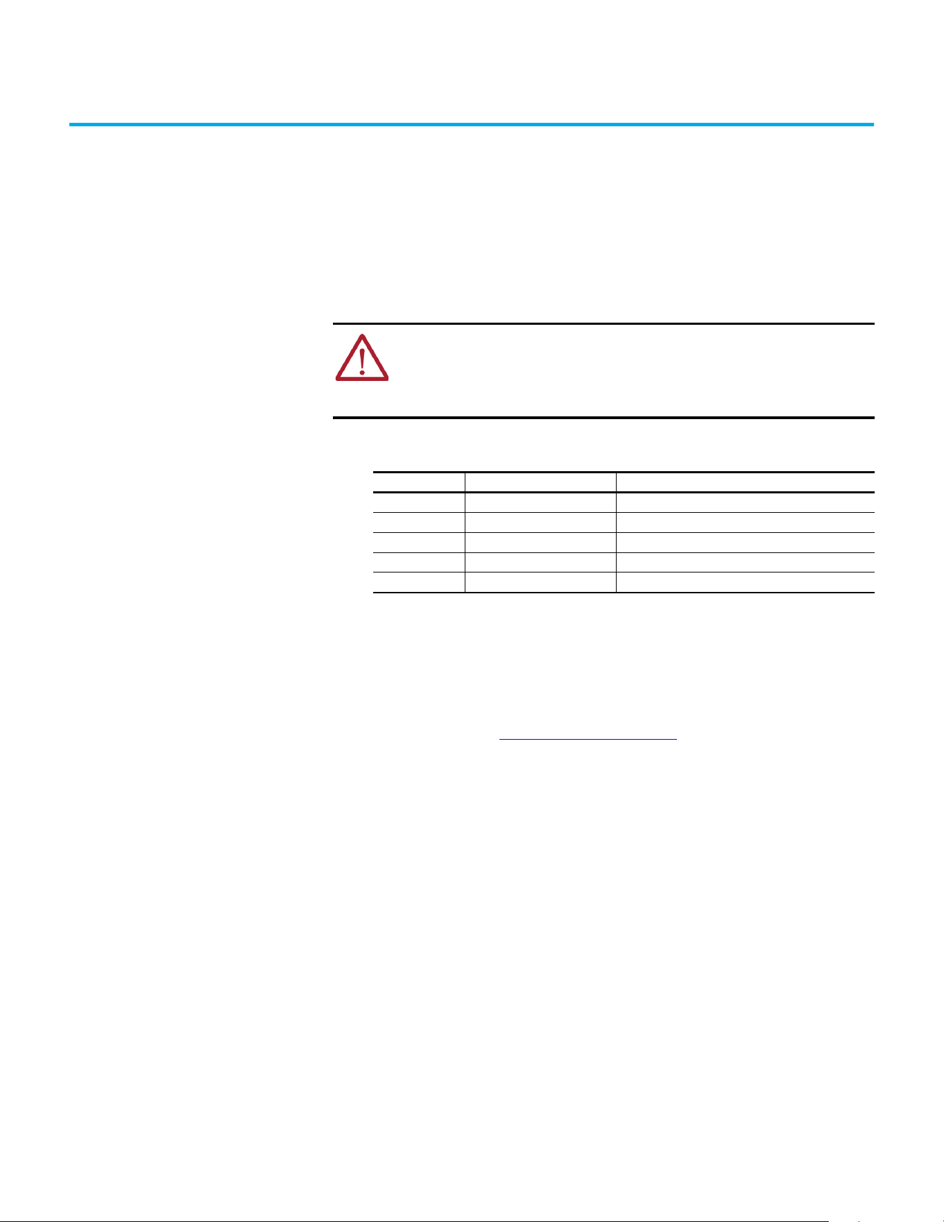
(1) For Frame E with Control Module Fan Kit only, clearance of 95 mm (3.7 in.) is required.
(2) For Frame E with Control Module Fan Kit only, clearance of 12 mm (0.5 in.) is required.
Vertical, Zero Stacking
No clearance between drives.
Horizontal, Zero Stacking with
Control Module Fan Kit
No clearance between drives.
Vertical Vertical, Zero Stacking with
Control Module Fan Kit
No clearance between drives.
Vertical with Control Module Fan Kit
Horizontal with Control Module Fan Kit
25 mm
(1.0 in.)
25 mm
(1.0 in.)
(2)
(2)
25 mm
(1.0 in.)
50 mm
(2.0 in.)
50 mm
(2.0 in.)
(1)
50 mm
(2.0 in.)
(1)
50 mm
(2.0 in.)
(1)
50 mm
(2.0 in.)
50 mm
(2.0 in.)
50 mm
(2.0 in.)
50 mm
(2.0 in.)
50 mm
(2.0 in.)
50 mm
(2.0 in.)
50 mm
(2.0 in.)
50 mm
(2.0 in.)
50 mm
(2.0 in.)
50 mm
(2.0 in.)
50 mm
(2.0 in.)
50 mm
(2.0 in.)
(1)
Rockwell Automation Publication 520-UM002E-EN-E - September 2024 15
Chapter 1 Installation/Wiring
Ambient Operating Temperatures
For optional accessories and kits, see Accessories and Dimensions on page 131.
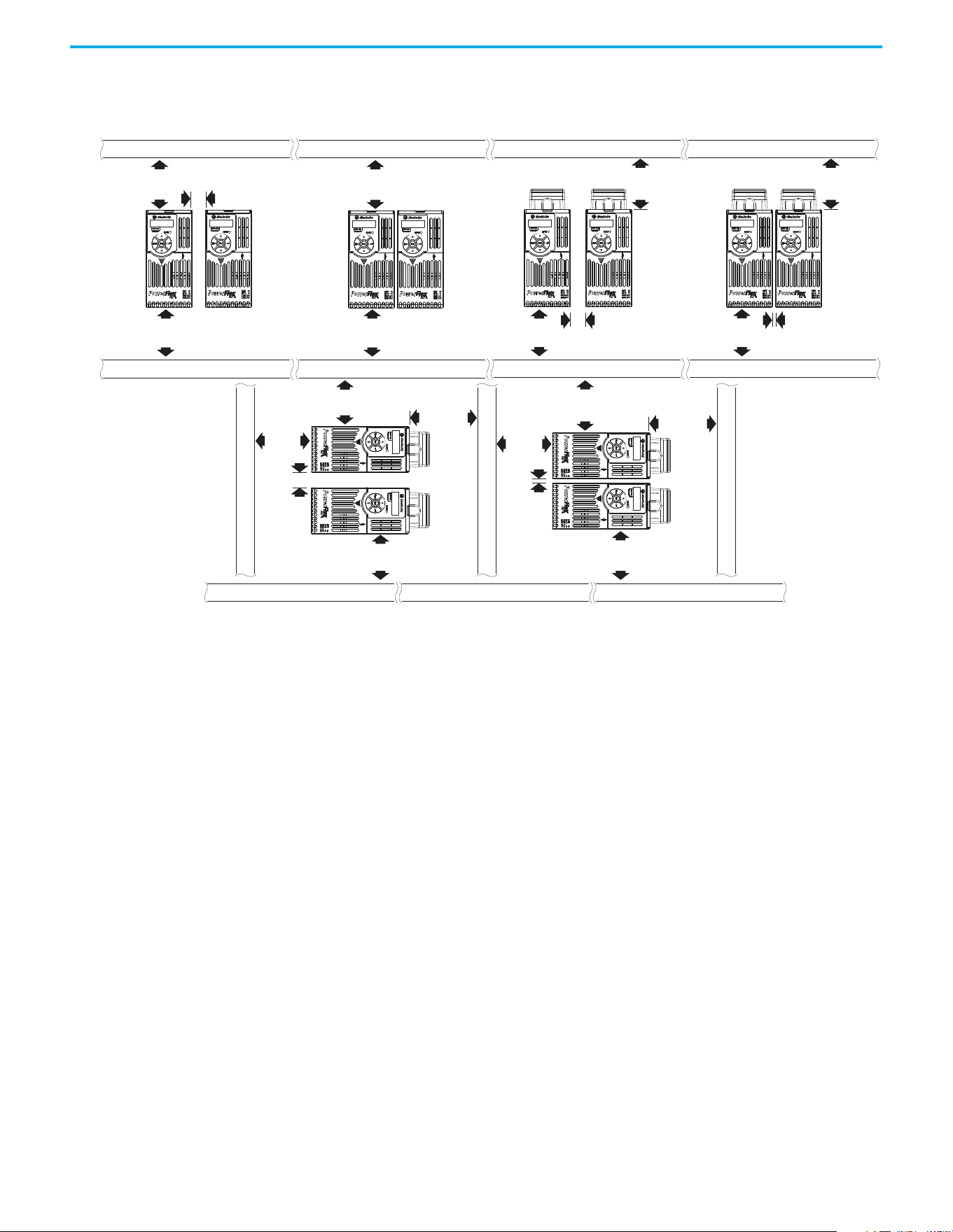
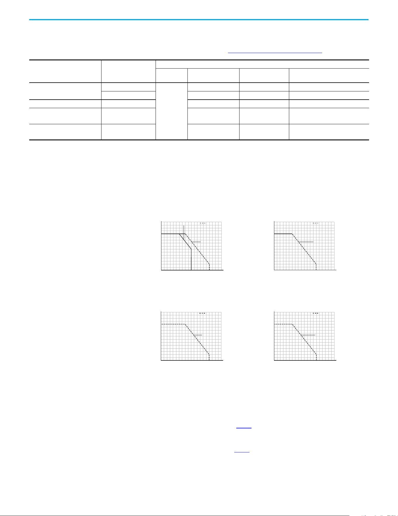
Current Derating Curves
Vertical Mounting
Horizontal/Floor Mounting
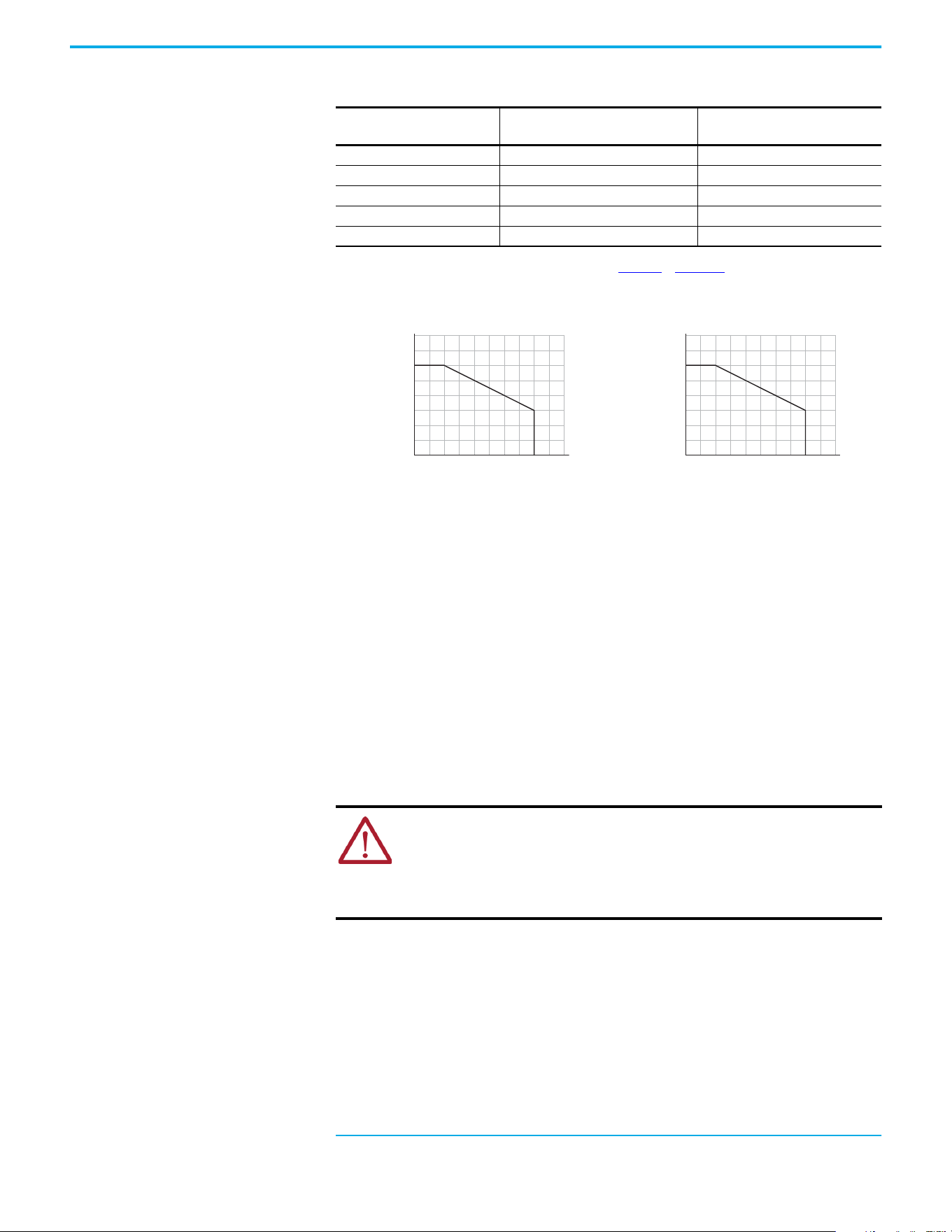
Derating Guidelines for High Altitude
The drive can be used without derating at a maximum altitude of 1000 m (3300 ft). If the drive is
used above 1000 m (3300 ft):
• Derate the maximum ambient temperature by 5 °C (9 °F) for every additional 1000 m
(3300 ft), subject to limits listed in Table 1
.
Or
• Derate the output current by 10% for every additional 1000 m (3300 ft), up to 3000 m
9900 ft), subject to limits listed in Table 1
.
Mounting Enclosure Rating
(1)
Ambient Temperature
Minimum Maximum (No Derate) Maximum (Derate)
(2)
Maximum with
Control Module Fan Kit (Derate)
(3)(5)
Vertical
IP 20/Open Type
-20 °C (-4 °F)
50 °C (122 °F) — 70 °C (158 °F)
IP 30/NEMA 1/UL Type 1 45 °C (113 °F) 55 °C (131 °F) –
Vertical, Zero Stacking IP 20/Open Type 45 °C (113 °F) — 65 °C (149 °F)
Horizontal with
Control Module Fan Kit
(4)(5)
IP 20/Open Type 50 °C (122 °F) — 70 °C (158 °F)
Horizontal, Zero Stacking
with Control Module Fan Kit
(4)(5)
IP 20/Open Type 45 °C (113 °F) — 65 °C (149 °F)
(1) IP 30/NEMA 1/UL Type 1 rating requires installation of the PowerFlex 520-Series IP 30/NEMA 1/UL Type 1 option kit, catalog number 25-JBAx.
(2) For catalogs 25C-D1P4N104 and 25C-E0P9N104, the temperature that is listed under the Maximum (Derate) column is reduced by 5 °C (9 °F) for all mounting methods.
(3) For catalogs 25C-D1P4N104 and 25C-E0P9N104, the temperature that is listed under the Maximum with Control Module Fan Kit (Derate) column is reduced by 10 °C (18 °F) for vertical and vertical with
zero stacking mounting methods only.
(4) Catalogs 25C-D1P4N104 and 25C-E0P9N104 cannot be mounted using either of the horizontal mounting methods.
(5) Requires installation of the PowerFlex 520-Series Control Module Fan Kit, catalog number 25-FANx-70C.
Single Drive Zero Stacking
Ambient Temperature (°C)
40
100
90
110
120
80
70
60
50
45403530
60 65 70 75 80
5550
Percentage of Rated Current (%)
IP 30/NEMA 1
with Control
Module Fan Kit
IP 20/Open Type
Ambient Temperature (°C)
40
100
90
110
120
80
70
60
50
45403530
60 65 70 75 80
5550
Percentage of Rated Current (%)
with Control
Module Fan Kit
IP 20/Open Type
Single Drive Zero Stacking
Ambient Temperature (°C)
40
100
90
120
110
80
70
60
50
30 35
70 75 80
60 6550 5540 45
Percentage of Rated Current (%)
with Control
Module Fan Kit
IP 20/Open Type
Ambient Temperature (°C)
40
100
90
120
110
80
70
60
50
30 35
70 75 80
60 6550 5540 45
Percentage of Rated Current (%)
with Control
Module Fan Kit
IP 20/Open Type
16 Rockwell Automation Publication 520-UM002E-EN-E - September 2024
Chapter 1 Installation/Wiring
High Altitude
Debris Protection
Take precautions to prevent debris from falling through the vents of the drive housing during
installation.
Storage
• Store within an ambient temperature range of -40…+85 °C (-140…+185 °F)
(1)
.
• Store within a relative humidity range of 0…95%, noncondensing.
• Do not expose to a corrosive atmosphere.
AC Supply Source
Considerations
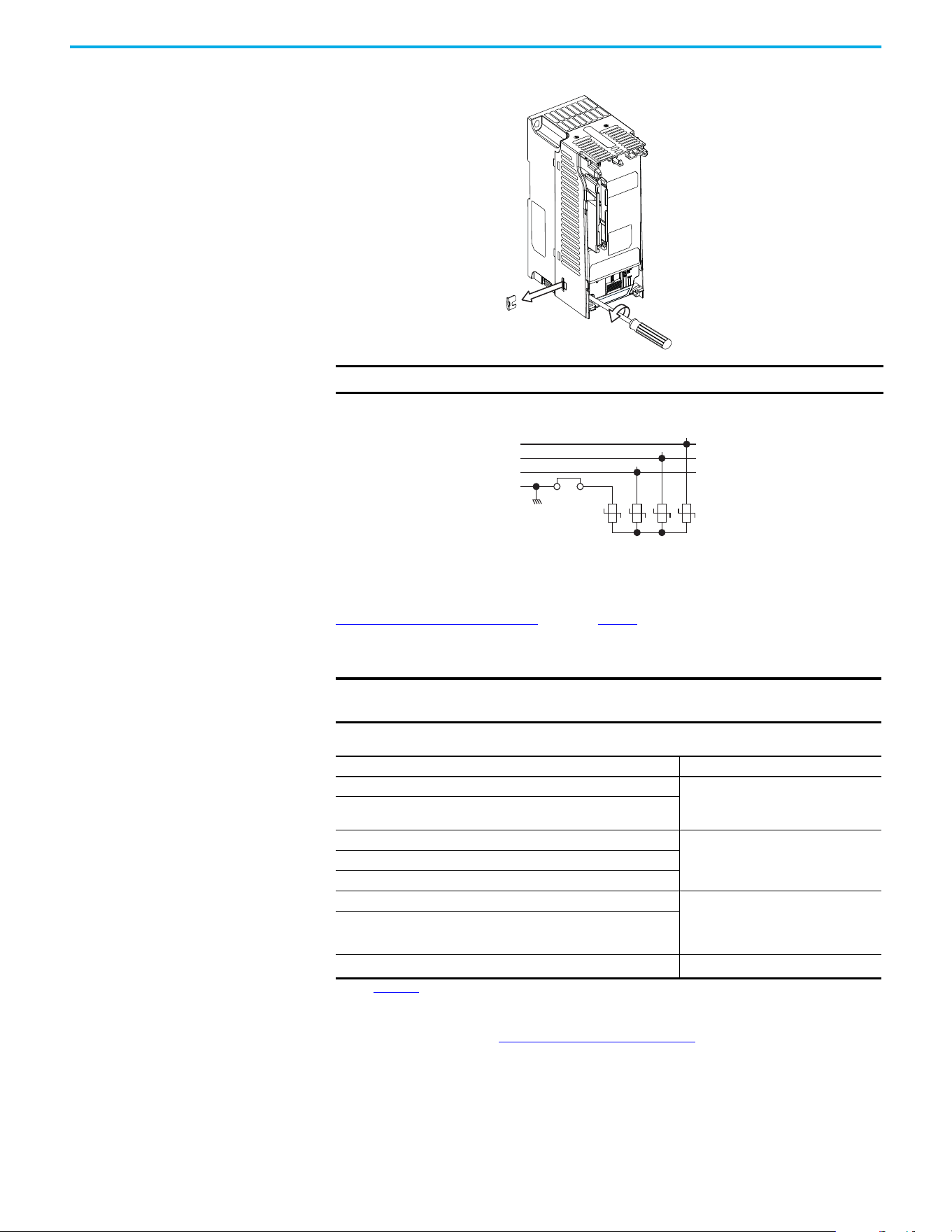
Ungrounded Distribution Systems
Disconnecting MOVs
To help prevent drive damage, the MOVs connected to ground shall be disconnected if the drive is
installed on an ungrounded distribution system (IT mains) where the line-to-ground voltages on
any phase could exceed 125% of the nominal line-to-line voltage. To disconnect these devices,
remove the jumper that is shown in the following diagrams.
1. Turn the screw counterclockwise to loosen.
2. Pull the jumper completely out of the drive chassis.
3. Tighten the screw to keep it in place.
Table 1 - Altitude Limit (Based on Voltage)
Drive Rating
Center Ground (Wye Neutral)
(1)
(1) The circuit breaker that is used in the drive may have different altitude specifications. See the Motor Protection Circuit Breaker and
Motor Circuit Protector Specifications Technical Data, publication 140-TD005 or 140M-TD002 for more information.
Corner Ground, Impedance Ground,
or Ungrounded
(1)(2)
(2) Impedance Ground and Ungrounded limits are not evaluated as part of UL specifications.
100…120V 1-phase 6000 m (19,685 ft) 6000 m (19,685 ft)
200…240V 1-phase 2000 m (6,562 ft) 2000 m (6,562 ft)
200…240V 3-phase 6000 m (19,685 ft) 2000 m (6,562 ft)
380…480V 3-phase 4000 m (13,123 ft) 2000 m (6,562 ft)
525…600V 3-phase 2000 m (6,562 ft) 2000 m (6,562 ft)
(1) The maximum ambient temperature for storing a Frame E drive is 70 °C (158 °F).
Altitude (m)
Percentage of Rated Current (%)
40
90
100
110
120
80
70
60
50
0
4000
300020001000
Altitude (m)
Ambient Temperature (°C)
20
50
60
40
30
0
4000
300020001000
ATTENTION:
• PowerFlex 527 drives contain protective MOVs that are referenced to ground.
These devices must be disconnected if the drive is installed on an ungrounded
or resistive grounded distribution system.
• Removing MOVs in drives with an embedded filter will also disconnect the filter
capacitor from earth ground.
Rockwell Automation Publication 520-UM002E-EN-E - September 2024 17
Chapter 1 Installation/Wiring
Jumper Location (Typical)
Phase to Ground MOV Removal
Input Power Conditioning
The drive is suitable for direct connection to input power within the rated voltage of the drive (see
Technical Specifications on page 125). Listed in Table 2 are certain input power conditions which
may cause component damage or reduction in product life. If any of these conditions exist, install
one of the devices that are listed under the heading Corrective Action on the line side of the drive.
IMPORTANT Tighten screw after jumper removal.
IMPORTANT Only one device per branch circuit is required. It should be mounted closest
to the branch and sized to handle the total current of the branch circuit.
Table 2 - Input Power Conditions
Input Power Condition Corrective Action
Low Line Impedance (less than 1% line reactance)
• Install Line Reactor.
(1)
or
• Install Isolation Transformer.
(1) See Appendix B for accessory ordering information.
Greater than 120 kVA supply transformer
Line has power factor correction capacitors
• Install Line Reactor.
(1)
or
• Install Isolation Transformer.
Line has frequent power interruptions
Line has intermittent noise spikes in excess of 6000V (lightning)
Phase to ground voltage exceeds 125% of normal line-to-line voltage • Remove MOV jumper to ground.
or
• Install Isolation Transformer with
grounded secondary if necessary.
Ungrounded distribution system
240V open delta configuration (stinger leg)
(2)
(2) For drives applied on an open delta with a middle phase grounded neutral system, the phase opposite the phase that is tapped in
the middle to the neutral or earth is referred to as the “stinger leg,” “high leg,” “red leg,” and so on. This leg should be identified
throughout the system with red or orange tape on the wire at each connection point. The stinger leg should be connected to the
center Phase B on the reactor. See Bulletin 1321-3R Series Line Reactors on page 137
for specific line reactor part numbers.
• Install Line Reactor.
(1)
Power module
R/L1
S/L2
T/L3
1234
3-phase AC
input
Jumper
18 Rockwell Automation Publication 520-UM002E-EN-E - September 2024
Chapter 1 Installation/Wiring
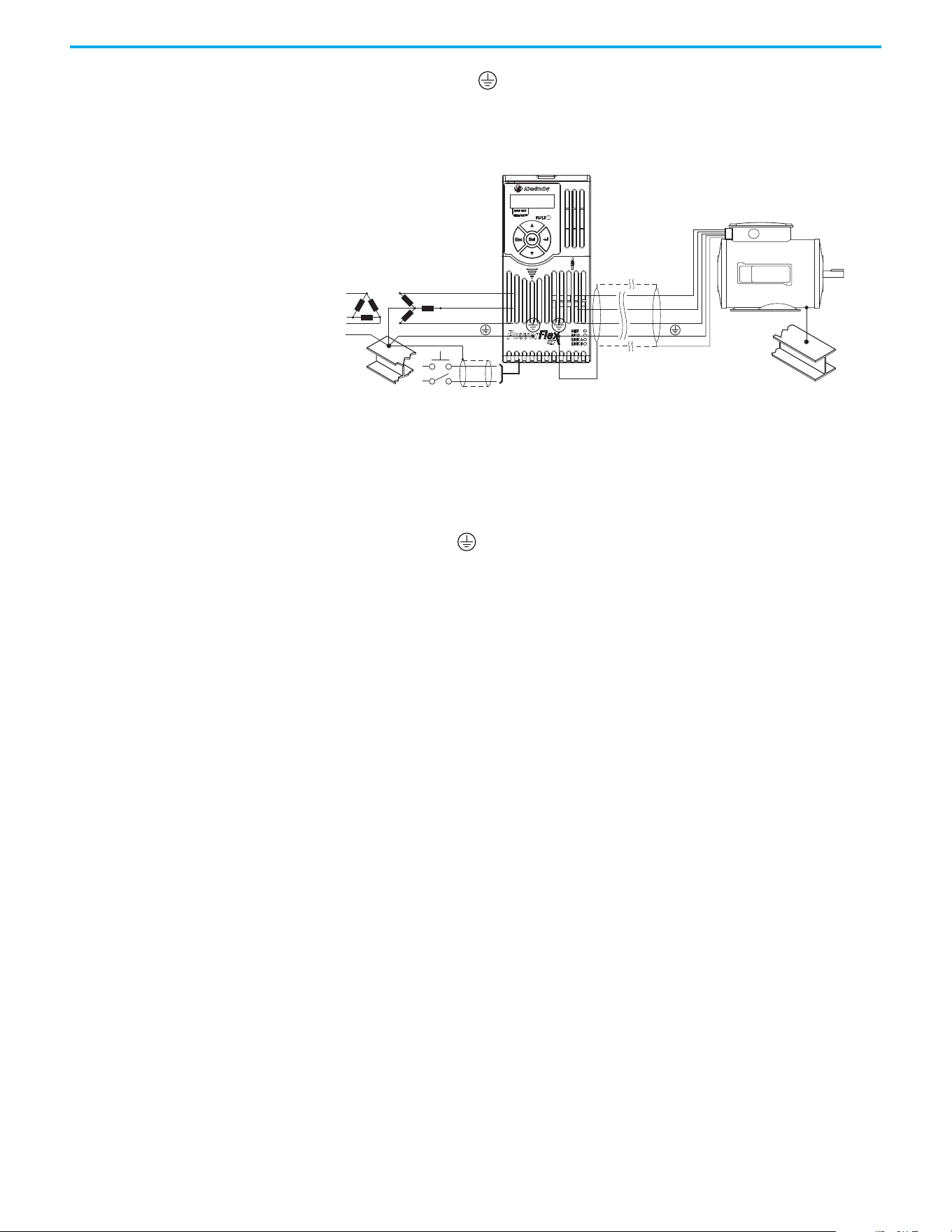
General Grounding
Requirements
The drive Safety Ground - (PE) must be connected to system ground. Ground impedance must
conform to the requirements of national and local industrial safety regulations and/or electrical
codes. The integrity of all ground connections should be periodically checked.
Typical Grounding
Ground Fault Monitoring
If a system ground fault monitor (RCD) is to be used, only Type B (adjustable) devices should be
used to avoid nuisance tripping.
Safety Ground - (PE)
This is the safety ground for the drive that is required by code. One of these points must be
connected to adjacent building steel (girder, joist), a floor ground rod, or busbar. Grounding points
must comply with national and local industrial safety regulations and/or electrical codes.
Motor Ground
The motor ground must be connected to one of the ground terminals on the drive.
Shield Termination - SHLD
Either of the safety ground terminals that are located on the power terminal block provides a
grounding point for the motor cable shield. The motor cable shield connected to one of these
terminals (drive end) should also be connected to the motor frame (motor end). Use a shield
terminating or EMI clamp to connect the shield to the safety ground terminal. The earthing plate or
conduit box option may be used with a cable clamp for a grounding point for the cable shield.
When shielded cable is used for control and signal wiring, the shield should be grounded at the
source end only, not at the drive end.
RFI Filter Grounding
Using a drive with filter may result in relatively high ground leakage currents. Therefore, the filter
must only be used in installations with grounded AC supply systems and be permanently
installed and solidly grounded (bonded) to the building power distribution ground. Verify that the
incoming supply neutral is solidly connected (bonded) to the same building power distribution
ground. Grounding must not rely on flexible cables and should exclude any form of plug or socket
that would permit inadvertent disconnection. Some local codes may require redundant ground
connections. The integrity of all connections should be periodically checked.
SHLD
U/T1
V/T2
W/T3
R/L1
S/L2
T/L3

Rockwell Automation Publication 520-UM002E-EN-E - September 2024 19
Chapter 1 Installation/Wiring
Fuses and Circuit Breakers The PowerFlex 527 drive does not provide branch short circuit protection. This product should be
installed with either input fuses or an input circuit breaker. National and local industrial safety
regulations and/or electrical codes may determine additional requirements for these installations.
The tables under Fuses and Circuit Breakers for PowerFlex 527 on page 19
provide recommended
AC line input fuse and circuit breaker information. See Fusing and Circuit Breakers below for UL and
IEC requirements. Sizes that are listed are the recommended sizes based on 40 °C (104 °F) and the
U.S. N.E.C. Other country, state, or local codes may require different ratings.
Fusing
The recommended fuse types are listed in the tables under Fuses and Circuit Breakers for
PowerFlex 527 on page 19. If available current ratings do not match those listed in the tables
provided, choose the next higher fuse rating.
• IEC – BS88 (British Standard) Parts 1 & 2
(1)
, EN60269-1, Parts 1 & 2, type GG or equivalent
should be used.
• UL – UL Class CC, T, or J should be used.
Circuit Breakers
The “non-fuse” listings in the tables under Fuses and Circuit Breakers for PowerFlex 527 on page 19
include inverse time circuit breakers, instantaneous trip circuit breakers (motor circuit protectors),
and 140M/140MT self-protected combination motor controllers. If one of these is chosen as the
desired protection method, the following requirements apply:
• IEC – Both types of circuit breakers and 140M/140MT self-protected combination motor
controllers are acceptable for IEC installations.
• UL – Only inverse time circuit breakers and the specified 140M/140MT self-protected
combination motor controllers are acceptable for UL installations.
Bulletin 140M/140MT (Self-protected Combination Controller)/UL489 Circuit Breakers
When using Bulletin 140M/140MT or UL489 rated circuit breakers, the following guidelines that are
listed must be followed to meet the NEC requirements for branch circuit protection.
• Bulletin 140M/140MT can be used in single motor applications.
• Bulletin 140M/140MT can be used up stream from the drive without the need for fuses.
If the DC Bus terminals or the Dynamic Brake terminals are used, the drive must be installed in an
enclosure and fuses must be used for input protection (for CE applications only). The ventilated
enclosure needs to be IP 20 rating or higher and at least 1.5x size larger than the drive.
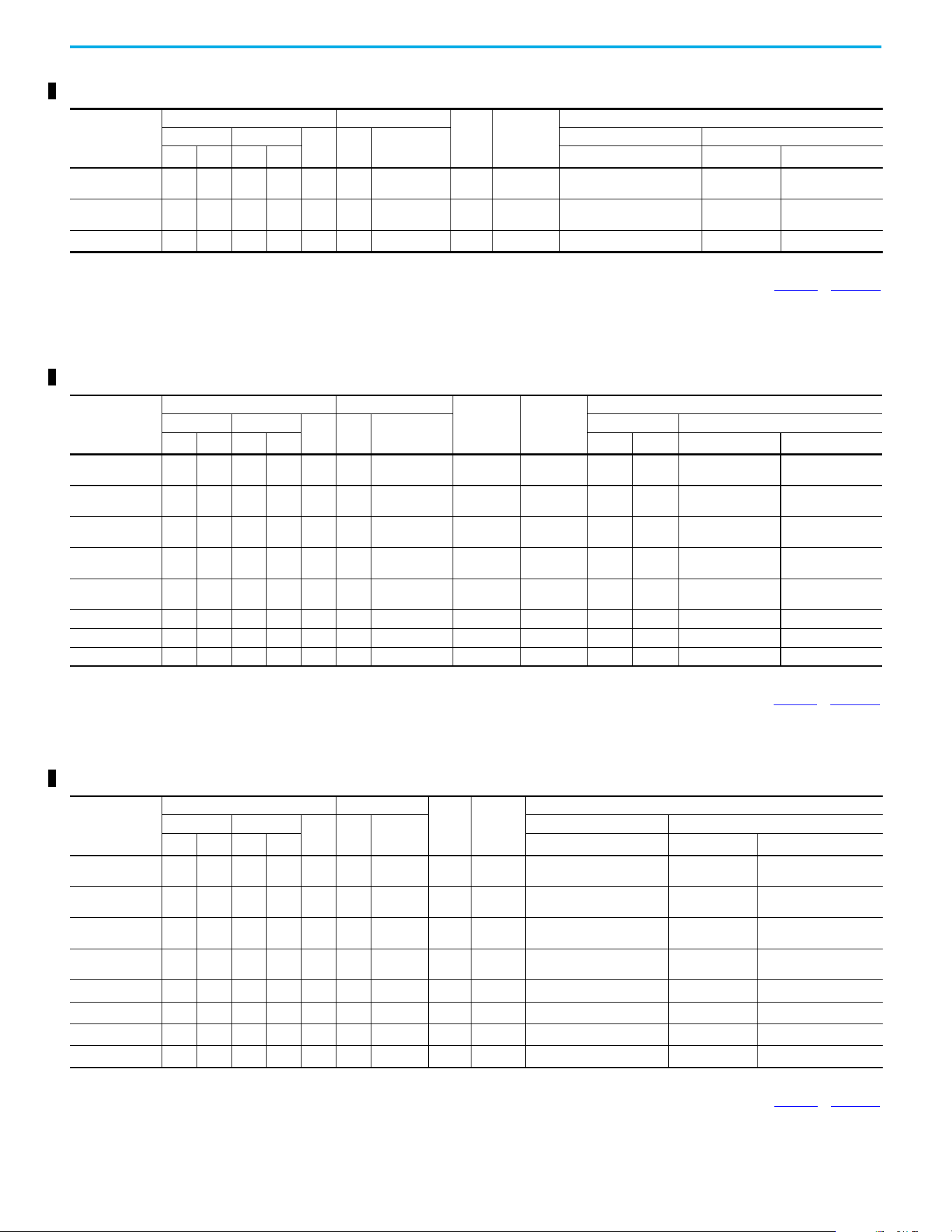
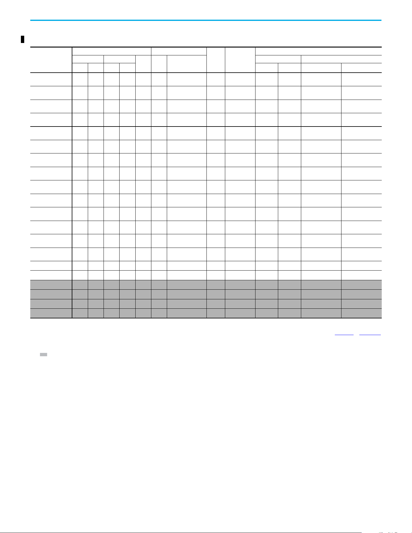
Fuses and Circuit Breakers for PowerFlex 527
(1) Typical designations include, but may not be limited to the following;
Parts 1 & 2: AC, AD, BC, BD, CD, DD, ED, EFS, EF, FF, FG, GF, GG, GH.
100...120V 1-phase Input Protection Devices – Frames A...B — IEC (Non-UL) Applications
Catalog Number
(1)
Output Ratings Input Ratings
Frame Size
Contactor
Catalog
Number
IEC (Non-UL) Applications
ND HD
AkVA
Max Current A
(2)
Fuses (Rating) Circuit Breakers
HP kW HP kW Min Max 140U/140UT
140M/140MT
(3)(4)(5)
25C-V2P5N104 0.5 0.4 0.5 0.4 2.5 1.3 9.6 A
100-C12
100-E12
16 20
140U-D6D2-C12
140UT-D7D2-C12
140M-C2E-C10
140MT-D9E-C10
25C-V4P8N104 1.0 0.75 1.0 0.75 4.8 2.5 19.2 B
100-C23
100-E26
25 40
140U-D6D2-C25
140UT-0702-C25
140M-D8E-C20
140MT-D9E-C20
25C-V6P0N104 1.5 1.1 1.5 1.1 6.0 3.2 24.0 B 100-C23 32 50
140U-D6D2-C30
14OUT-D702-C30
140M-F8E-C25
(1) 150% Overload capability for up to 60 s, 180% for up to 3 s.
(2) When the drive is controlling motors with lower amp ratings, see the drive nameplate for drive input current rating.
(3) The AIC ratings of the Bulletin 140M/140MT devices can vary. See the Motor Protection Circuit Breaker and Motor Circuit Protector Specifications Technical Data, publication 140-TD005
or 140M-TD002.
(4) Bulletin 140M/140MT with adjustable current range should have the current trip set to the minimum range that the device does not trip.
(5) Manual Self-protected (Type E) Combination Motor Controller, UL Listed for 480Y/277 and 600Y/347 AC input. Not UL Listed for use on 480V or 600V Delta/Delta, corner ground, or high-resistance
ground systems.
20 Rockwell Automation Publication 520-UM002E-EN-E - September 2024
Chapter 1 Installation/Wiring
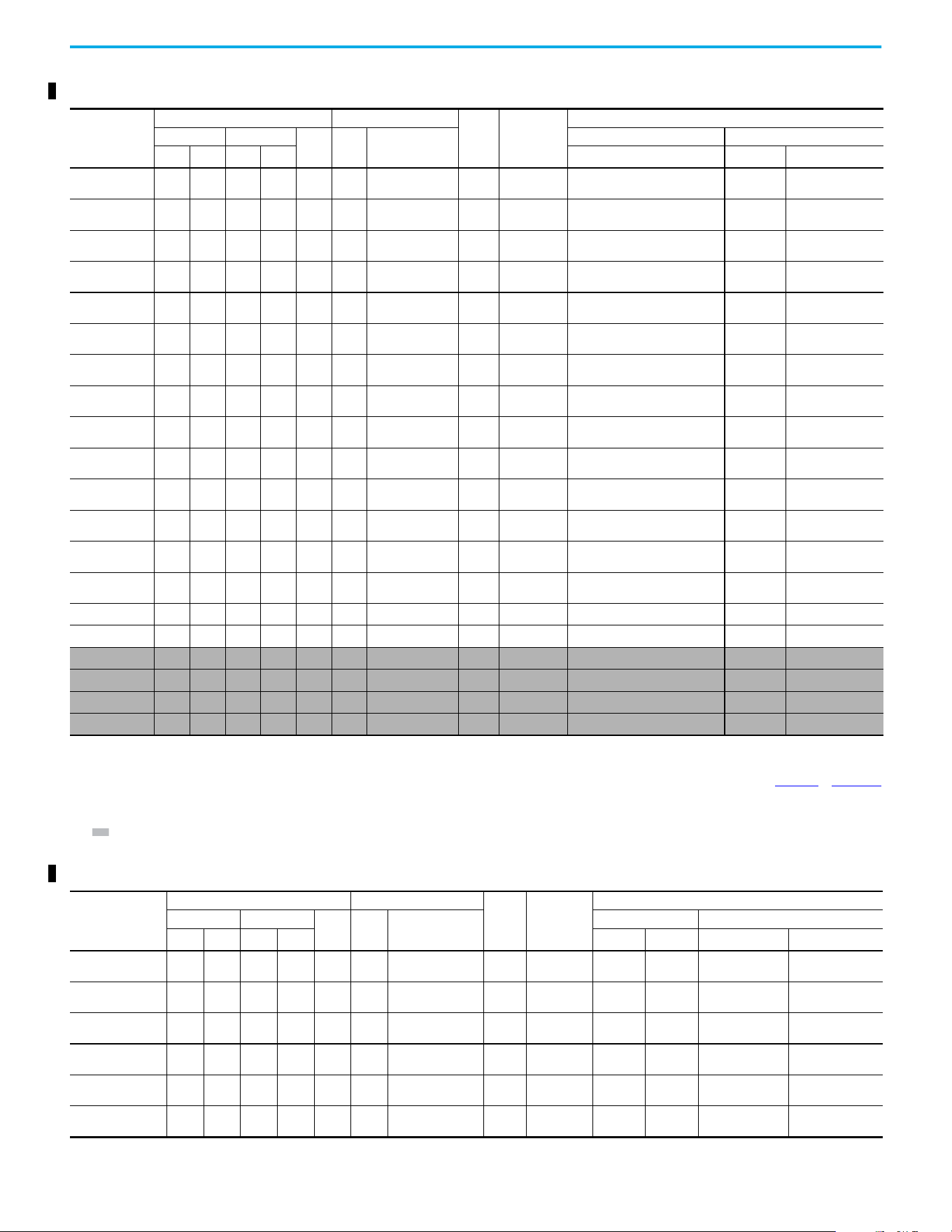
100...120V 1-phase Input Protection Devices – Frames A...B — UL 61800-5-1 Applications
Catalog Number
(1)
Output Ratings Input Ratings
Frame
Size
Contactor
Catalog
Number
UL 61800-5-1 Applications
ND HD
AkVA
Max Current A
(2)
Fuses (Max. Rating) Circuit Breakers
HP kW HP kW Class / Catalog Number 140UT
140M/140MT
(3)(4)(5)
25C-V2P5N104 0.5 0.4 0.5 0.4 2.5 1.3 9.6 A
100-C12
100-E12
CLASS CC, J, or T/20 140UT-D7D2-C12
140MT-C3E-C10
140MT-D9E-C10
25C-V4P8N104 1.0 0.75 1.0 0.75 4.8 2.5 19.2 B
100-C23
100-E26
CLASS CC, J, or T/40
—
(6)
140MT-D9E-C20
25C-V6P0N104 1.5 1.1 1.5 1.1 6.0 3.2 24.0 B 100-C23 CLASS CC, J, or T/50
—
(6)
140M-F8E-C25
(1) 150% Overload capability for up to 60 s, 180% for up to 3 s.
(2) When the drive is controlling motors with lower amp ratings, see the drive nameplate for drive input current rating.
(3) The AIC ratings of the Bulletin 140M/140MT devices can vary. See the Motor Protection Circuit Breaker and Motor Circuit Protector Specifications Technical Data, publication 140-TD005
or 140M-TD002.
(4) Bulletin 140M/140MT with adjustable current range should have the current trip set to the minimum range that the device does not trip.
(5) Manual Self-protected (Type E) Combination Motor Controller, UL Listed for 480Y/277 and 600Y/347 AC input. Not UL Listed for use on 480V or 600V Delta/Delta, corner ground, or high-resistance
ground systems.
(6) Circuit breaker selection is not available for this drive rating.
200...240V 1-phase Input Protection Devices – Frames A...B — IEC (Non-UL) Applications
Catalog Number
(1)
Output Ratings Input Ratings
Frame Size
Contactor
Catalog
Number
IEC (Non-UL) Applications
ND HD
AkVA
Max Current A
(2)
Fuses (Rating) Circuit Breakers
HP kW HP kW Min Max 140U/140UT/140G
140M/140MT
(3)(4)(5)
25C-A2P5N104 0.5 0.4 0.5 0.4 2.5 1.7 6.5 A
100-C09
100-E09
10 16
140U-D6D2-C10
140UT-D702-C10
140M-C2E-C10
140MT-C3E-C10
25C-A2P5N114 0.5 0.4 0.5 0.4 2.5 1.7 6.5 A
100-C09
100-E09
10 16
140U-D6D2-C10
140UT-D702-C10
140M-C2E-C10
140MT-C3E-C10
25C-A4P8N104 1.0 0.75 1.0 0.75 4.8 2.8 10.7 A
100-C12
100-E12
16 25
140U-D6D2-C15
140UT-D702-C15
140M-C2E-C16
140MT-C3E-C16
25C-A4P8N114 1.0 0.75 1.0 0.75 4.8 2.8 10.7 A
100-C12
100-E12
16 25
140U-D6D2-C15
140UT-D702-C15
140M-C2E-C16
140MT-C3E-C16
25C-A8P0N104 2.0 1.5 2.0 1.5 8.0 4.8 18.0 B 100-C23 25 40
140U-D6D2-C25
140UT-D7D2-C25
140M-F8E-C25
25C-A8P0N114 2.0 1.5 2.0 1.5 8.0 4.8 18.0 B 100-C23 25 40 140U-D6D2-C25 140M-F8E-C25
25C-A011N104 3.0 2.2 3.0 2.2 11.0 6.0 22.9 B 100-C37 32 50 140G-G6C3-C25 140M-F8E-C25
25C-A011N114 3.0 2.2 3.0 2.2 11.0 6.0 22.9 B 100-C37 32 50 140G-G6C3-C25 140M-F8E-C25
(1) 150% Overload capability for up to 60 s, 180% for up to 3 s.
(2) When the drive is controlling motors with lower amp ratings, see the drive nameplate for drive input current rating.
(3) The AIC ratings of the Bulletin 140M/140MT devices can vary. See the Motor Protection Circuit Breaker and Motor Circuit Protector Specifications Technical Data, publication 140-TD005
or 140M-TD002.
(4) Bulletin 140M/140MT with adjustable current range should have the current trip set to the minimum range that the device does not trip.
(5) Manual Self-protected (Type E) Combination Motor Controller, UL Listed for 480Y/277 and 600Y/347 AC input. Not UL Listed for use on 480V or 600V Delta/Delta, corner ground, or high-resistance
ground systems.
200...240V 1-phase Input Protection Devices – Frames A...B — UL 61800-5-1 Applications
Catalog Number
(1)
Output Ratings Input Ratings
Frame
Size
Contactor
Catalog
Number
UL 61800-5-1 Applications
ND HD
AkVA
Max
Current A
(2)
Fuses (Max. Rating) Circuit Breakers
HP kW HP kW Class / Catalog Number 140UT
140M/140MT
(3)(4)(5)
25C-A2P5N104 0.5 0.4 0.5 0.4 2.5 1.7 6.5 A
100-C09
100-E09
CLASS CC, J, or T/15 140UT-D7D2-C10 140MT-D9E-C10
25C-A2P5N114 0.5 0.4 0.5 0.4 2.5 1.7 6.5 A
100-C09
100-E09
CLASS CC, J, or T/15 140UT-D7D2-C10 140MT-D9E-C10
25C-A4P8N104 1.0 0.75 1.0 0.75 4.8 2.8 10.7 A
100-C12
100-E12
CLASS CC, J, or T/25 140UT-D7D2-C15 140MT-D9E-C16
25C-A4P8N114 1.0 0.75 1.0 0.75 4.8 2.8 10.7 A
100-C12
100-E12
CLASS CC, J, or T/25 140UT-D7D2-C15 140MT-D9E-C16
25C-A8P0N104 2.0 1.5 2.0 1.5 8.0 4.8 18.0 B 100-C23 CLASS CC, J, or T/40
—
(6)
140M-F8E-C25
25C-A8P0N114 2.0 1.5 2.0 1.5 8.0 4.8 18.0 B 100-C23 CLASS CC, J, or T/40
—
(6)
140M-F8E-C25
25C-A011N104 3.0 2.2 3.0 2.2 11.0 6.0 22.9 B 100-C37 CLASS CC, J, or T/50
—
(6)
140M-F8E-C25
25C-A011N114 3.0 2.2 3.0 2.2 11.0 6.0 22.9 B 100-C37 CLASS CC, J, or T/50
—
(6)
140M-F8E-C25
(1) 150% Overload capability for up to 60 s, 180% for up to 3 s.
(2) When the drive is controlling motors with lower amp ratings, see the drive nameplate for drive input current rating.
(3) The AIC ratings of the Bulletin 140M/140MT devices can vary. See the Motor Protection Circuit Breaker and Motor Circuit Protector Specifications Technical Data. publication 140-TD005
or 140M-TD002.
(4) Bulletin 140M/140MT with adjustable current range should have the current trip set to the minimum range that the device does not trip.
(5) Manual Self-protected (Type E) Combination Motor Controller, UL Listed for 480Y/277 and 600Y/347 AC input. Not UL Listed for use on 480V or 600V Delta/Delta, corner ground, or high-resistance
ground systems.
(6) Circuit breaker selection is not available for this drive rating.
Rockwell Automation Publication 520-UM002E-EN-E - September 2024 21
Chapter 1 Installation/Wiring
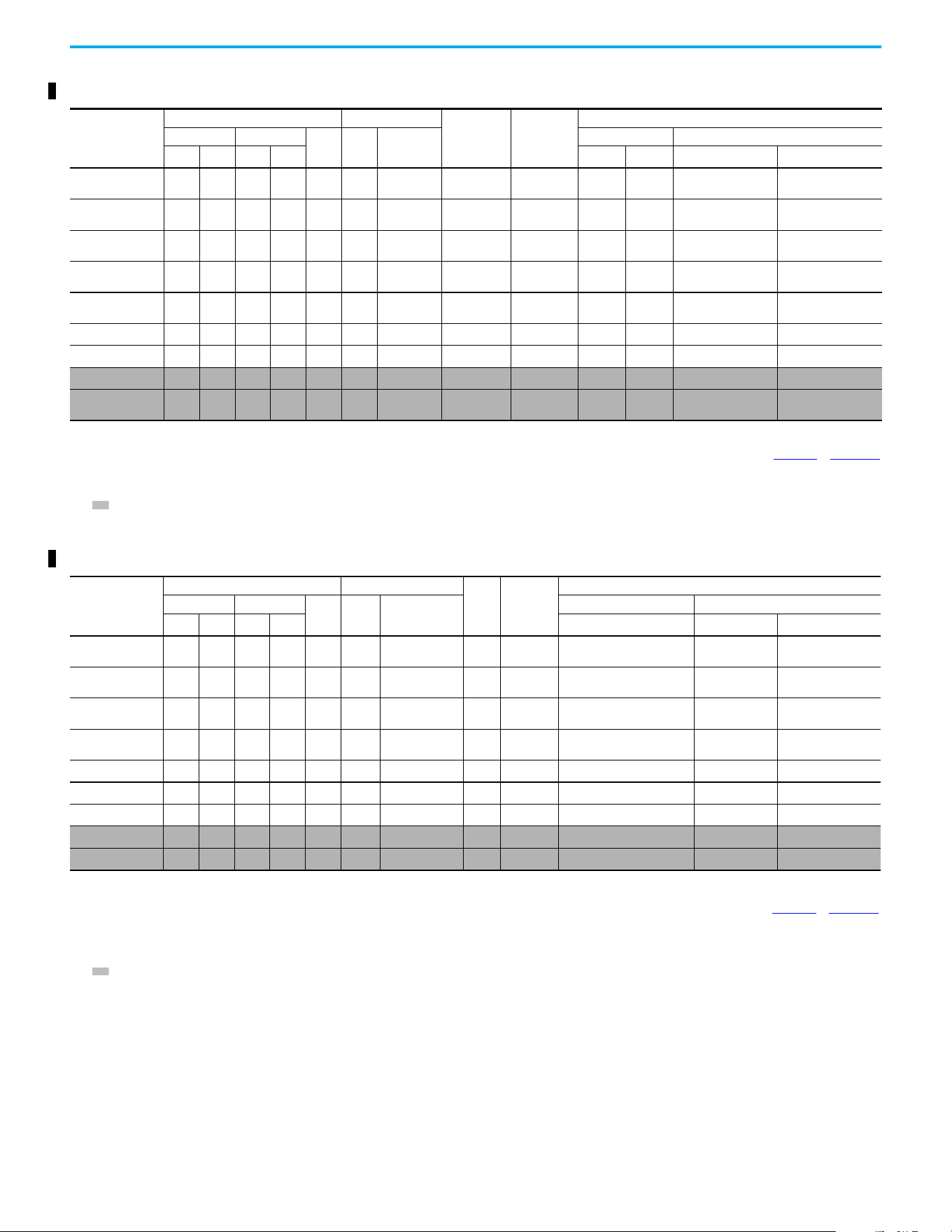
200...240V 3-phase Input Protection Devices – Frames A...B — IEC (Non-UL) Applications
Catalog Number
(1)
Output Ratings Input Ratings
Frame Size
Contactor
Catalog
Number
IEC (Non-UL) Applications
ND HD
AkVA
Max Current
A
(2)
Fuses (Rating) Circuit Breakers
HP kW HP kW Min Max 140U/140UT/140G
140M/140MT
(3)(4)(5)
25C-B2P5N104 0.5 0.4 0.5 0.4 2.5 1.2 2.7 A
100-C09
100-E09
66
140U-D6D3-B40
140UT-D703-B40
140M-C2E-B40
140MT-C3E-B40
25C-B5P0N104
1.0 0.75 1.0 0.75 5.0 2.7 5.8 A
100-C09
100-E09
10 16
140U-D6D3-B80
140UT-D703-B80
140M-C2E-B63
140MT-C3E-B63
25C-B8P0N104
2.0 1.5 2.0 1.5 8.0 4.3 9.5 A
100-C12
100-E12
16 20
140U-D6D3-C10
140UT-D7D3-C10
140M-C2E-C10
140MT-C3E-C10
25C-B011N104
3.0 2.2 3.0 2.2 11.0 6.3 13.8 A
100-C23
100-E26
20 32
140U-D6D3-C15
140UT-D7D3-C15
140M-C2E-C16
140MT-C3E-C16
25C-B017N104
5.0 4.0 5.0 4.0 17.5 9.6 21.1 B 100-C23 32 45
140U-D6D3-C25
140UT-D7D3-C25
140M-F8E-C25
25C-B024N104
7.5 5.5 7.5 5.5 24.0 12.2 26.6 C 100-C37 35 63 140G-G6C3-C35 140M-F8E-C32
25C-B032N104
10.0 7.5 10.0 7.5 32.2 15.9 34.8 D 100-C43 45 70 140G-G6C3-C60 140M-F8E-C45
25C-B048N104
(6)
15.0 11.0 10.0 7.5 48.3 20.1 44.0 E 100-C60 63 90 140G-G6C3-C70 140M-F8E-C45
25C-B062N104
(6)
20.0 15.0 15.0 11.0 62.1 25.6 56.0 E
100-C72
100-E65
70 125 140G-G6C3-C90
—
(7)
(1) 150% Overload capability for up to 60 s, 180% for up to 3 s.
(2) When the drive is controlling motors with lower amp ratings, see the drive nameplate for drive input current rating.
(3) The AIC ratings of the Bulletin 140M/140MT devices can vary. See the Motor Protection Circuit Breaker and Motor Circuit Protector Specifications Technical Data, publication 140-TD005 or 140M-TD002.
(4) Bulletin 140M/140MT with adjustable current range should have the current trip set to the minimum range that the device does not trip.
(5) Manual Self-protected (Type E) Combination Motor Controller, UL Listed for 480Y/277 and 600Y/347 AC input. Not UL Listed for use on 480V or 600V Delta/Delta, corner ground, or high-resistance
ground systems.
(6) 110% Overload capability for up to 60 s, 150% for up to 3 s.
(7) Circuit breaker selection is not available for this drive rating.
200...240V 3-phase Input Protection Devices – Frames A...E — UL 61800-5-1 Applications
Catalog Number
(1)
Output Ratings Input Ratings
Frame
Size
Contactor
Catalog
Number
UL 61800-5-1 Applications
ND HD
AkVA
Max Current A
(2)
Fuses (Max. Rating) Circuit Breakers
HP kW HP kW Class / Catalog Number 140UT
140M/140MT
(3)(4)(5)
25C-B2P5N104 0.5 0.4 0.5 0.4 2.5 1.2 2.7 A
100-C09
100-E09
CLASS CC, J, or T/6 140UT-D7D3-B40 140MT-D9E-B40
25C-B5P0N104
)
1.0 0.75 1.0 0.75 5.0 2.7 5.8 A
100-C09
100-E09
CLASS CC, J, or T/15 140UT-D7D3-B80 140MT-D9E-B63
25C-B8P0N104
2.0 1.5 2.0 1.5 8.0 4.3 9.5 A
100-C12
100-E12
CLASS CC, J, or T/20 140UT-D7D3-C10 140MT-D9E-C10
25C-B011N104
3.0 2.2 3.0 2.2 11.0 6.3 13.8 A
100-C23
100-E26
CLASS CC, J, or T/30 140UT-D7D3-C15 140MT-D9E-C16
25C-B017N104
5.0 4.0 5.0 4.0 17.5 9.6 21.1 B 100-C23 CLASS CC, J, or T/45 140UT-D7D3-C25 140M-F8E-C25
25C-B024N104
7.5 5.5 7.5 5.5 24.0 12.2 26.6 C 100-C37 CLASS CC, J, or T/60
—
(6)
140M-F8E-C32
25C-B032N104
10.0 7.5 10.0 7.5 32.2 15.9 34.8 D 100-C43 CLASS CC, J, or T/70
—
(6)
140M-F8E-C45
25C-B048N104
(7)
15.0 11.0 10.0 7.5 48.3 20.1 44.0 E 100-C60 CLASS CC, J, or T/90
—
(6)
140M-F8E-C45
25C-B062N104
(7)
20.0 15.0 15.0 11.0 62.1 25.6 56.0 E 100-C72 CLASS CC, J, or T/125
—
(6)
—
(6)
(1) 150% Overload capability for up to 60 s, 180% for up to 3 s.
(2) When the drive is controlling motors with lower amp ratings, see the drive nameplate for drive input current rating.
(3) The AIC ratings of the Bulletin 140M/140MT devices can vary. See the Motor Protection Circuit Breaker and Motor Circuit Protector Specifications Technical Data, publication 140-TD005
or 140M-TD002.
(4) Bulletin 140M/140MT with adjustable current range should have the current trip set to the minimum range that the device does not trip.
(5) Manual Self-protected (Type E) Combination Motor Controller, UL Listed for 480Y/277 and 600Y/347 AC input. Not UL Listed for use on 480V or 600V Delta/Delta, corner ground, or high-resistance
ground systems.
(6) Circuit breaker selection is not available for this drive rating.
(7) 110% Overload capability for up to 60 s, 150% for up to 3 s.
22 Rockwell Automation Publication 520-UM002E-EN-E - September 2024
Chapter 1 Installation/Wiring
380...480V 3-phase Input Protection Devices – Frames A...E— IEC (Non-UL) Applications
Catalog No
(1)
Output Ratings Input Ratings
Frame
Size
Contactor
Catalog
Number
IEC (Non-UL) Applications
ND HD
AkVA
Max Current A
(2)
Fuses (Rating) Circuit Breakers
HP kW HP kW Min Max 140U/140UT/140G
140M/140MT
(3)(4)(5)
25C-D1P4N104 0.5 0.4 0.5 0.4 1.4 1.7 1.9 A
100-C09
100-E09
36
140U-D6D3-B30
140UT-D7D3-B30
140M-C2E-B25
140MT-C3E-B25
25C-D1P4N114
0.5 0.4 0.5 0.4 1.4 1.7 1.9 A
100-C09
100-E09
36
140U-D6D3-B30
140UT-D7D3-B30
140M-C2E-B25
140MT-C3E-B25
25C-D2P3N104
1.0 0.75 1.0 0.75 2.3 2.9 3.2 A
100-C09
100-E09
610
140U-D6D3-B60
140UT-D7D3-B60
140M-C2E-B40
140MT-C3E-B40
25C-D2P3N114
1.0 0.75 1.0 0.75 2.3 2.9 3.2 A
100-C09
100-E09
610
140U-D6D3-B60
140UT-D7D3-B60
140M-C2E-B40
140MT-C3E-B40
25C-D4P0N104
2.01.52.01.54.05.2 5.7 A
100-C09
100-E09
10 16
140U-D6D3-B60
140UT-D7D3-B60
140M-C2E-B63
40MT-C3E-B63
25C-D4P0N114
2.01.52.01.54.05.2 5.7 A
100-C09
100-E09
10 16
140U-D6D3-B60
140UT-D7D3-B60
140M-C2E-B63
40MT-C3E-B63
25C-D6P0N104
3.0 2.2 3.0 2.2 6.0 6.9 7.5 A
100-C09
100-E09
10 16
140U-D6D3-C10
140UT-D7D3-C10
140M-C2E-C10
140MT-C3E-C10
25C-D6P0N114
3.0 2.2 3.0 2.2 6.0 6.9 7.5 A
100-C09
100-E09
10 16
140U-D6D3-C10
140UT-D7D3-C10
140M-C2E-C10
140MT-C3E-C10
25C-D010N104
5.0 4.0 5.0 4.0 10.5 12.6 13.8 B
100-C23
100-E26
20 32
140U-D6D3-C15
140UT-D7D3-C15
140M-C2E-C16
140MT-C3E-C16
25C-D010N114
5.0 4.0 5.0 4.0 10.5 12.6 13.8 B
100-C23
100-E26
20 32
140U-D6D3-C15
140UT-D7D3-C15
140M-C2E-C16
140MT-C3E-C16
25C-D013N104
7.5 5.5 7.5 5.5 13.0 14.1 15.4 C
100-C23
100-E26
20 35
140U-D6D3-C25
140UT-D7D3-C25
140M-D8E-C20
140MT-D9E-C20
25C-D013N114
7.5 5.5 7.5 5.5 13.0 14.1 15.4 C
100-C23
100-E26
20 35
140U-D6D3-C25
140UT-D7D3-C25
140M-D8E-C20
140MT-D9E-C20
25C-D017N104
10.0 7.5 10.0 7.5 17.0 16.8 18.4 C
100-C23
100-E26
25 40
140U-D6D3-C25
140UT-D7D3-C25
140M-D8E-C20
140MT-D9E-C20
25C-D017N114
10.0 7.5 10.0 7.5 17.0 16.8 18.4 C
100-C23
100-E26
25 40
140U-D6D3-C25
140UT-D7D3-C25
140M-D8E-C20
140MT-D9E-C20
25C-D024N104
15.0 11.0 15.0 11.0 24.0 24.1 26.4 D 100-C37 35 63 140G-G6C3-C40 140M-F8E-C32
25C-D024N114
15.0 11.0 15.0 11.0 24.0 24.1 26.4 D 100-C37 35 63 140G-G6C3-C40 140M-F8E-C32
25C-D030N104
(6)
20.0 15.0 15.0 11.0 30.0 30.2 33.0 D 100-C43 45 70 140G-G6C3-C50 140M-F8E-C45
25C-D030N114
(6)
20.0 15.0 15.0 11.0 30.0 30.2 33.0 D 100-C43 45 70 140G-G6C3-C50 140M-F8E-C45
25C-D037N114
(6)
25.0 18.5 20.0 15.0 37.0 30.8 33.7 E 100-C43 45 70 140G-G6C3-C50 140M-F8E-C45
25C-D043N114
(6)
30.0 22.0 25.0 18.5 43.0 35.6 38.9 E 100-C60 50 80 140G-G6C3-C60 140M-F8E-C45
(1) 150% Overload capability for up to 60 s, 180% for up to 3 s.
(2) When the drive is controlling motors with lower ampere ratings, see the drive nameplate for drive input current rating.
(3) The AIC ratings of the Bulletin 140M/140MT devices can vary. See the Motor Protection Circuit Breaker and Motor Circuit Protector Specifications Technical Data, publication 140-TD005
or 140M-TD002.
(4) Bulletin 140M/140MT with adjustable current range should have the current trip set to the minimum range that the device does not trip.
(5) Manual Self-protected (Type E) Combination Motor Controller, UL Listed for 480Y/277 and 600Y/347 AC input. Not UL Listed for use on 480V or 600V Delta/Delta, corner ground, or high-resistance
ground systems.
(6) 110% Overload capability for up to 60 s, 150% for up to 3 s.
Rockwell Automation Publication 520-UM002E-EN-E - September 2024 23
Chapter 1 Installation/Wiring
380…480V 3-phase Input Protection Devices – Frames A…E — UL 61800-5-1 Applications
Catalog
Number
(1)
Output Ratings Input Ratings
Frame
Size
Contactor
Catalog
Number
UL 61800-5-1 Applications
ND HD
AkVA
Max Current A
(2)
Fuses (Max Rating) Circuit Breakers
HP kW HP kW Class/Catalog Number
140UT
(3)
140M/140MT
(4)(5)(6)
25C-D1P4N104 0.5 0.4 0.5 0.4 1.4 1.7 1.9 A
100-C09
100-E09
CLASS CC, J, or T/6 — 140MT-C3E-B25
25C-D1P4N114
0.5 0.4 0.5 0.4 1.4 1.7 1.9 A
100-C09
100-E09
CLASS CC, J, or T/6 — 140MT-C3E-B25
25C-D2P3N104
1.0 0.75 1.0 0.75 2.3 2.9 3.2 A
100-C09
100-E09
CLASS CC, J, or T/10 — 140MT-C3E-B40
25C-D2P3N114
1.0 0.75 1.0 0.75 2.3 2.9 3.2 A
100-C09
100-E09
CLASS CC, J, or T/10 — 140MT-C3E-B40
25C-D4P0N104
2.01.52.01.54.05.2 5.7 A
100-C09
100-E09
CLASS CC, J, or T/15 — 140MT-C3E-B63
25C-D4P0N114
2.01.52.01.54.05.2 5.7 A
100-C09
100-E09
CLASS CC, J, or T/15 — 140MT-C3E-B63
25C-D6P0N104
3.0 2.2 3.0 2.2 6.0 6.9 7.5 A
100-C09
100-E09
CLASS CC, J, or T/15 — 140MT-C3E-C10
25C-D6P0N114
3.0 2.2 3.0 2.2 6.0 6.9 7.5 A
100-C09
100-E09
CLASS CC, J, or T/15 — 140MT-C3E-C10
25C-D010N104
5.0 4.0 5.0 4.0 10.5 12.6 13.8 B
100-C23
100-E26
CLASS CC, J, or T/30 — 140MT-D9E-C16
25C-D010N114
5.0 4.0 5.0 4.0 10.5 12.6 13.8 B
100-C23
100-E26
CLASS CC, J, or T/30 — 140MT-D9E-C16
25C-D013N104
7.5 5.5 7.5 5.5 13.0 14.1 15.4 C
100-C23
100-E26
CLASS CC, J, or T/35 — 140MT-D9E-C20
25C-D013N114
7.5 5.5 7.5 5.5 13.0 14.1 15.4 C
100-C23
100-E26
CLASS CC, J, or T/35 — 140MT-D9E-C20
25C-D017N104
10.0 7.5 10.0 7.5 17.0 16.8 18.4 C
100-C23
100-E26
CLASS CC, J, or T/40 — 140MT-D9E-C20
25C-D017N114
10.0 7.5 10.0 7.5 17.0 16.8 18.4 C
100-C23
100-E26
CLASS CC, J, or T/40 — 140MT-D9E-C20
25C-D024N104
15.0 11.0 15.0 11.0 24.0 24.1 26.4 D 100-C37 CLASS CC, J, or T/60 — 140M-F8E-C32
25C-D024N114
15.0 11.0 15.0 11.0 24.0 24.1 26.4 D 100-C37 CLASS CC, J, or T/60 — 140M-F8E-C32
25C-D030N104
(7)
20.0 15.0 15.0 11.0 30.0 30.2 33.0 D 100-C43 CLASS CC, J, or T/70 — 140M-F8E-C45
25C-D030N114
(7)
20.0 15.0 15.0 11.0 30.0 30.2 33.0 D 100-C43 CLASS CC, J, or T/70 — 140M-F8E-C45
25C-D037N114
(7)
25.0 18.5 20.0 15.0 37.0 30.8 33.7 E 100-C43 CLASS CC, J, or T/70 — 140M-F8E-C45
25C-D043N114
(7)
30.0 22.0 25.0 18.5 43.0 35.6 38.9 E 100-C60 CLASS CC, J, or T/80 — 140M-F8E-C45
(1) 150% Overload capability for up to 60 s, 180% for up to 3 s.
(2) When the drive is controlling motors with lower ampere ratings, see the drive nameplate for drive input current rating.
(3) Circuit breaker selection is not available for this drive rating.
(4) The AIC ratings of the Bulletin 140M/140MT devices can vary. See the Motor Protection Circuit Breaker and Motor Circuit Protector Specifications Technical Data, publication 140-TD005
or 140M-TD002.
(5) Bulletin 140M/140MT with adjustable current range should have the current trip set to the minimum range that the device does not trip.
(6) Manual Self-protected (Type E) Combination Motor Controller, UL Listed for 480Y/277 and 600Y/347 AC input. Not UL Listed for use on 480V or 600V Delta/Delta, corner ground, or high-resistance
ground systems.
(7) 110% Overload capability for up to 60 s, 150% for up to 3 s.
525…600V 3-phase Input Protection Devices – Frames A…E — IEC (Non-UL) Applications
Catalog Number
(1)
Output Ratings Input Ratings
Frame
Size
Contactor
Catalog
Number
IEC (Non-UL) Applications
ND HD
AkVA
Max Current A
(2)
Fuses (Rating) Circuit Breakers
HP kW HP kW Min Max 140U/140UT/140G
140M/140MT
(3)(4)(5)
25C-E0P9N104 0.5 0.4 0.5 0.4 0.9 1.4 1.2 A
100-C09
100-E09
36
140U-D6D3-B20
140UT-D7D3-B20
140M-C2E-B25
140MT-C3E-B25
25C-E1P7N104
1.0 0.75 1.0 0.75 1.7 2.6 2.3 A
100-C09
100-E09
36
140U-D6D3-B30
140UT-D7D3-B30
140M-C2E-B25
140MT-C3E-B25
25C-E3P0N104
2.0 1.5 2.0 1.5 3.0 4.3 3.8 A
100-C09
100-E09
610
140U-D6D3-B50
140ut-D7D3-B50
140M-C2E-B40
140MT-C3E-B40
25C-E4P2N104
3.0 2.2 3.0 2.2 4.2 6.1 5.3 A
100-C09
100-E09
10 16
140U-D6D3-B80
140UT-D7D3-B80
140M-C2E-B63
140MT-D9E-B63
25C-E6P6N104
5.0 4.0 5.0 4.0 6.6 9.1 8.0 B
100-C09
100-E09
10 20
140U-D6D3-C10
140UT-D7D3-C10
140M-C2E-C10
140MT-D9E-C10
25C-E9P9N104
7.5 5.5 7.5 5.5 9.9 12.8 11.2 C
100-C16
100-E16
16 25
140U-D6D3-C15
140UT-D7D3-C15
140M-C2E-C16
140MT-D9E-C16
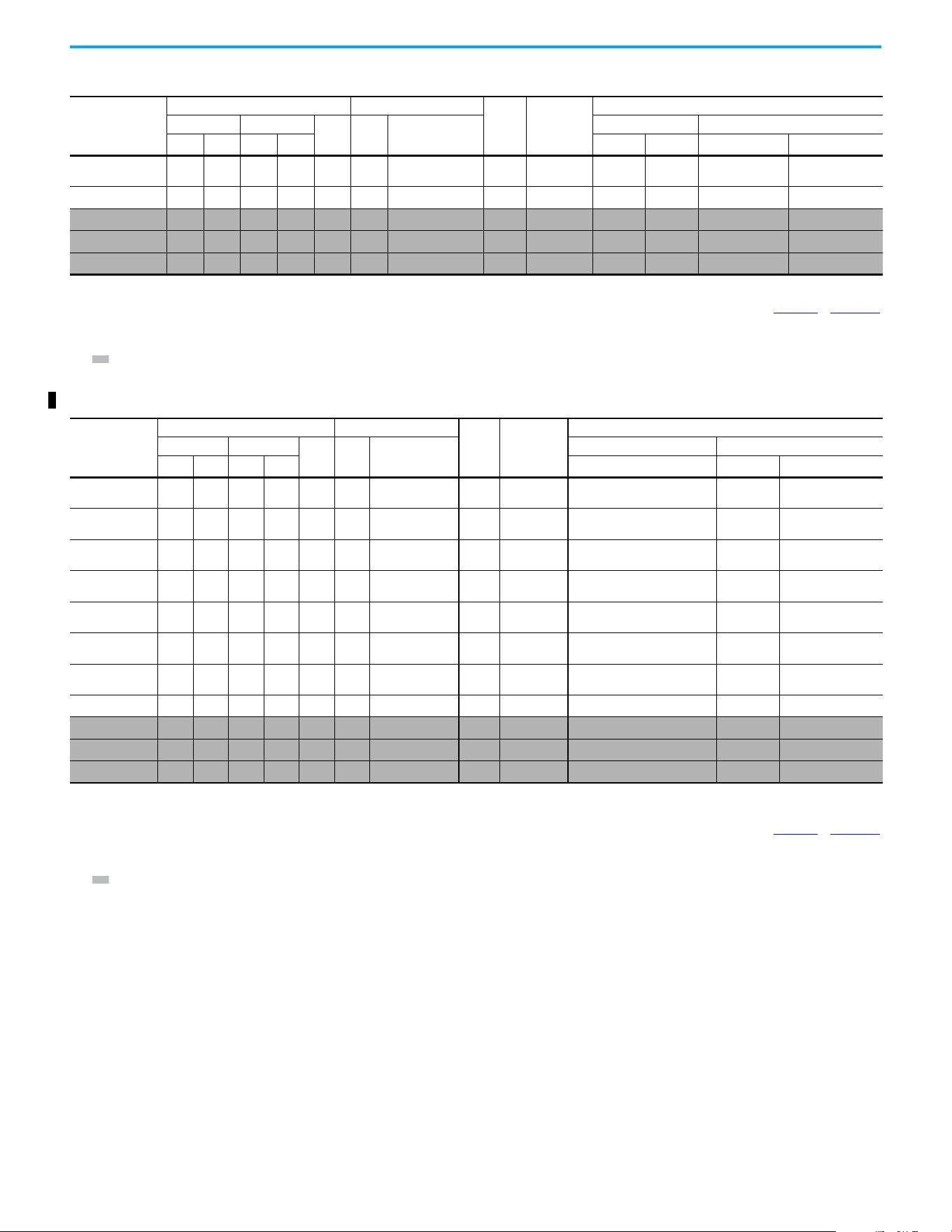
24 Rockwell Automation Publication 520-UM002E-EN-E - September 2024
Chapter 1 Installation/Wiring
25C-E012N104
10.0 7.5 10.0 7.5 12.0 15.4 13.5 C
100-C23
100-E26
20 32 140U-D6D3-C20
140M-C2E-C16
140MT-D9E-C16
25C-E019N104
15.0 11.0 15.0 11.0 19.0 27.4 24.0 D 100-C30 32 50 140G-G6C3-C30 140M-F8E-C25
25C-E022N104
(6)
20.0 15.0 15.0 11.0 22.0 31.2 27.3 D 100-C30 35 63 140G-G6C3-C35 140M-F8E-C32
25C-E027N104
(6)
25.0 18.5 20.0 15.0 27.0 28.2 24.7 E 100-C30 35 50 140G-G6C3-C35 140M-F8E-C32
25C-E032N104
(6)
30.0 22.0 25.0 18.5 32.0 33.4 29.2 E 100-C37 40 63 140G-G6C3-C50 140M-F8E-C32
(1) 150% Overload capability for up to 60 s, 180% for up to 3 s.
(2) When the drive is controlling motors with lower ampere ratings, see the drive nameplate for drive input current rating.
(3) The AIC ratings of the Bulletin 140M/140MT devices can vary. See the Motor Protection Circuit Breaker and Motor Circuit Protector Specifications Technical Data, publication 140-TD005
or 140M-TD002.
(4) Bulletin 140M/140MT with adjustable current range should have the current trip set to the minimum range that the device does not trip.
(5) Manual Self-protected (Type E) Combination Motor Controller, UL Listed for 480Y/277 and 600Y/347 AC input. Not UL Listed for use on 480V or 600V Delta/Delta, corner ground, or high-resistance
ground systems.
(6) 110% Overload capability for up to 60 s, 150% for up to 3 s.
525…600V 3-phase Input Protection Devices – Frames A…E — IEC (Non-UL) Applications (Continued)
Catalog Number
(1)
Output Ratings Input Ratings
Frame
Size
Contactor
Catalog
Number
IEC (Non-UL) Applications
ND HD
AkVA
Max Current A
(2)
Fuses (Rating) Circuit Breakers
HP kW HP kW Min Max 140U/140UT/140G
140M/140MT
(3)(4)(5)
525…600V 3-phase Input Protection Devices – Frames A…E — UL 61800-5-1 Applications
Catalog Number
(1)
Output Ratings Input Ratings
Frame
Size
Contactor
Catalog
Number
UL 61800-5-1 Applications
ND HD
AkVA
Max Current A
(2)
Fuses (Max Rating) Circuit Breakers
HP kW HP kW Class/Catalog Number
140UT
(3)
140M/140MT
(4)(5)(6)
25C-E0P9N104 0.5 0.4 0.5 0.4 0.9 1.4 1.2 A
100-C09
100-E09
CLASS CC, J, or T/6 — 140MT-C3E-B25
25C-E1P7N104
1.0 0.75 1.0 0.75 1.7 2.6 2.3 A
100-C09
100-E09
CLASS CC, J, or T/6 — 140MT-C3E-B25
25C-E3P0N104
2.0 1.5 2.0 1.5 3.0 4.3 3.8 A
100-C09
100-E09
CLASS CC, J, or T/10 — 140MT-C3E-B40
25C-E4P2N104
3.0 2.2 3.0 2.2 4.2 6.1 5.3 A
100-C09
100-E09
CLASS CC, J, or T/15 — 140MT-D9E-B63
25C-E6P6N104
5.0 4.0 5.0 4.0 6.6 9.1 8.0 B
100-C09
100-E09
CLASS CC, J, or T/20 — 140MT-D9E-C10
25C-E9P9N104
7.55.57.55.59.912.8 11.2 C
100-C16
100-E16
CLASS CC, J, or T/25 — 140MT-D9E-C16
25C-E012N104
10.0 7.5 10.0 7.5 12.0 15.4 13.5 C
100-C23
100-E26
CLASS CC, J, or T/30 — 140MT-D9E-C16
25C-E019N104
15.0 11.0 15.0 11.0 19.0 27.4 24.0 D 100-C30 CLASS CC, J, or T/50 — 140M-F8E-C25
25C-E022N104
(7)
20.0 15.0 15.0 11.0 22.0 31.2 27.3 D 100-C30 CLASS CC, J, or T/60 — 140M-F8E-C32
25C-E027N104
(7)
25.0 18.5 20.0 15.0 27.0 28.2 24.7 E 100-C30 CLASS CC, J, or T/50 — 140M-F8E-C32
25C-E032N104
(7)
30.0 22.0 25.0 18.5 32.0 33.4 29.2 E 100-C37 CLASS CC, J, or T/60 — 140M-F8E-C32
(1) 150% Overload capability for up to 60 s, 180% for up to 3 s.
(2) When the drive is controlling motors with lower ampere ratings, see the drive nameplate for drive input current rating.
(3) Circuit breaker selection is not available for this drive rating.
(4) The AIC ratings of the Bulletin 140M/140MT devices can vary. See the Motor Protection Circuit Breaker and Motor Circuit Protector Specifications Technical Data, publication 140-TD005
or 140M-TD002.
(5) Bulletin 140M/140MT with adjustable current range should have the current trip set to the minimum range that the device does not trip.
(6) Manual Self-protected (Type E) Combination Motor Controller, UL Listed for 208V Wye or Delta, 240V Wye or Delta, 480V Y/277 or 600V Y/347. Not UL Listed for use on 480V or 600V Delta/Delta, corner
ground, or high-resistance ground systems.
(7) 110% Overload capability for up to 60 s, 150% for up to 3 s.
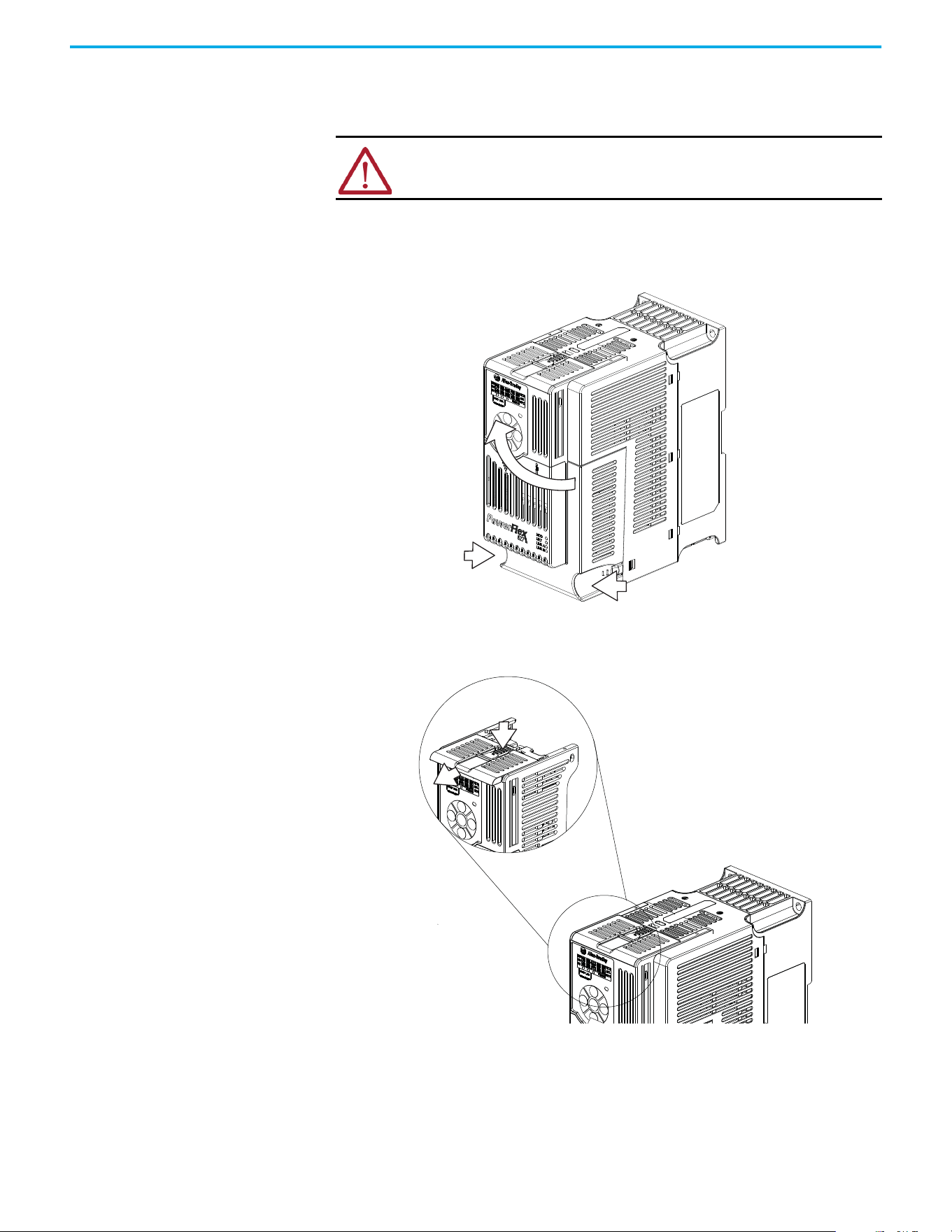
Rockwell Automation Publication 520-UM002E-EN-E - September 2024 25
Chapter 1 Installation/Wiring
Power and Control Module
PowerFlex 527 drives consist of a Power Module and Control Module. This section describes how to
separate the two modules and reconnect them back together, and also how to access the power
terminals and control terminals. It is assumed that your drive is new and has not been installed.
Separating the Power and Control Module
1. Press and hold down the catch on both sides of the frame cover, then pull out and swing
upwards to remove (Frames B…E only).
2. Press down and slide out the top cover of the Control Module to unlock it from the Power
Module.
ATTENTION: If you are performing these steps on a drive that has been
installed, verify that the drive is powered down and the DC Bus voltage is less
than 50V DC before proceeding.
1
2
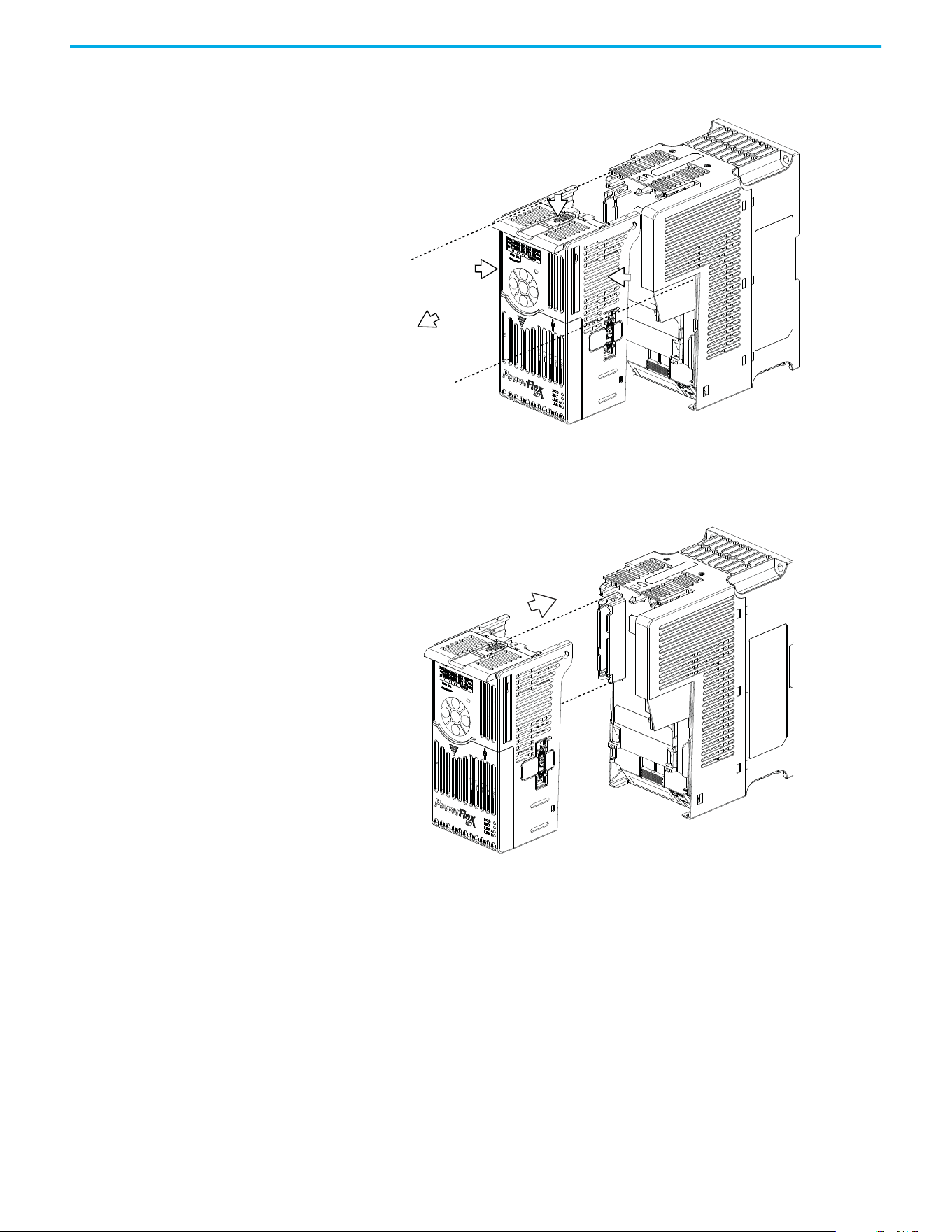
26 Rockwell Automation Publication 520-UM002E-EN-E - September 2024
Chapter 1 Installation/Wiring
3. Hold the sides and top of the Control Module firmly, then pull out to separate it from the
Power Module.
Connecting the Power and Control Module
1. Align the connectors on the Power Module and Control Module, then push the Control Module
firmly onto the Power Module.
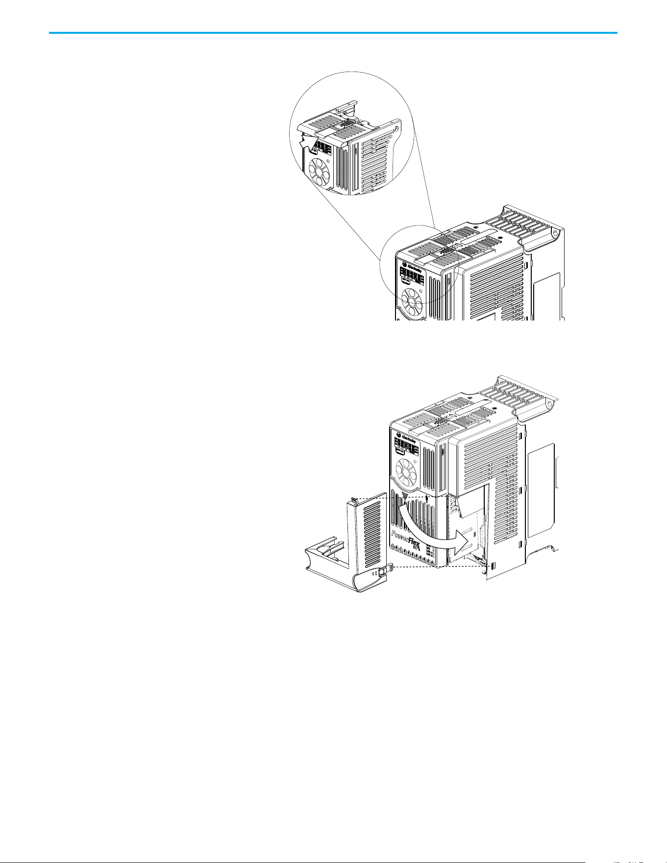
Rockwell Automation Publication 520-UM002E-EN-E - September 2024 27
Chapter 1 Installation/Wiring
2. Push the top cover of the Control Module towards the Power Module to lock it.
3. Insert the catch at the top of the frame cover into the Power Module, then swing the frame
cover to snap the side catches onto the Power Module (Frames B...E only).
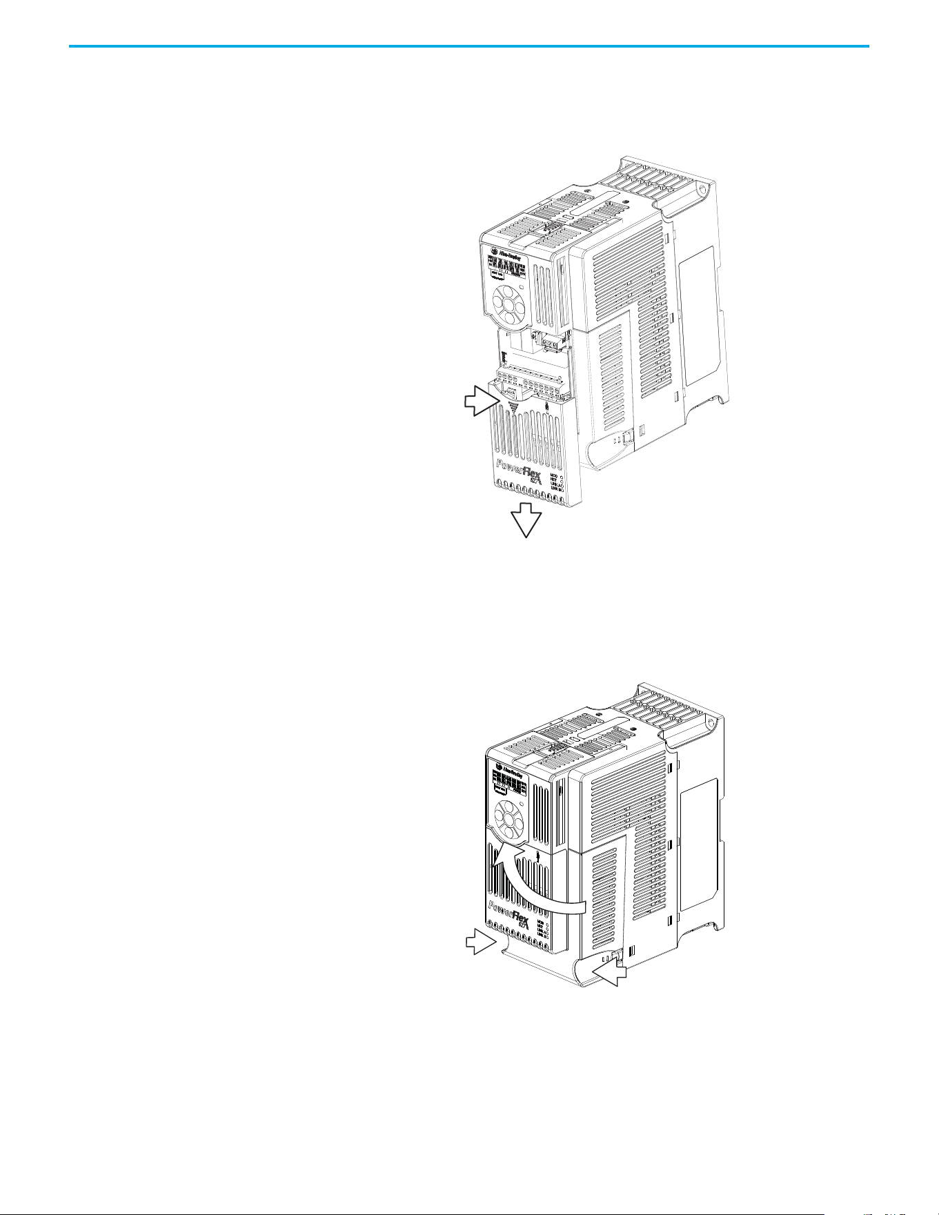
28 Rockwell Automation Publication 520-UM002E-EN-E - September 2024
Chapter 1 Installation/Wiring
Control Module Cover To access the control terminals, the front cover must be removed. To remove:
1. Press and hold down the arrow on the front of the cover.
2. Slide the front cover down to remove from the Control Module.
Reattach the front cover when wiring is complete.
Power Module Terminal
Guard
To access the power terminals, the terminal guard must be removed. To remove:
1. Press and hold down the catch on both sides of the frame cover, then pull out and swing
upwards to remove (Frames B…E only).
.
2. Press and hold down the locking tab on the terminal guard.
1
2
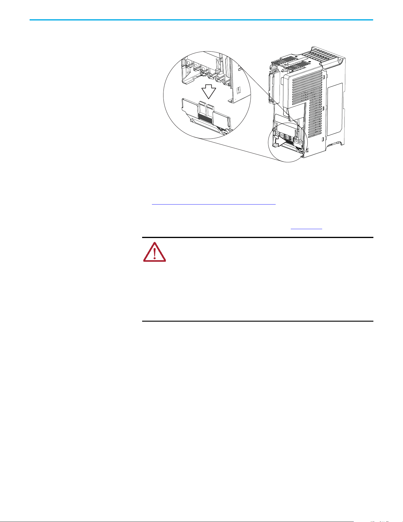
Rockwell Automation Publication 520-UM002E-EN-E - September 2024 29
Chapter 1 Installation/Wiring
3. Slide the terminal guard down to remove from the Power Module.
.
Reattach the terminal guard when wiring is complete.
To access the power terminals for Frame A, you need to separate the Power and Control Modules.
See Separating the Power and Control Module on page 25
for instructions.
Power Wiring For general wiring and grounding practices, see the Wiring and Grounding for Pulse Width
Modulated (PWM) AC Drives Installation Instructions, publication DRIVES-IN001.
Motor Cable Types Acceptable for 100…600 Volt Installations
A variety of cable types are acceptable for drive installations. For many installations, unshielded
cable is adequate, provided it can be separated from sensitive circuits. As an approximate guide,
allow a spacing of 0.3 m (1 ft) for every 10 m (32.8 ft) of length. In all cases, long parallel runs must
be avoided. Do not use cable with an insulation thickness less than 15 mils (0.4 mm/0.015 in.). Do
not route more than three sets of motor leads in one conduit to minimize “cross talk”. If more than
three drive/motor connections per conduit are required, shielded cable must be used.
• UL installations above 50 °C (122 °F) ambient must use 600V, 90 °C (194 °F) wire.
• UL installations in 50 °C (122 °F) ambient must use 600V, 75 °C or 90 °C (167 °F or 194 °F)
wire.
• UL installations in 40 °C (104 °F) ambient should use 600V, 75 °C or 90 °C (167 °F or 194 °F)
wire.
Use copper wire only. Wire gauge requirements and recommendations are tables that are provided
on 75 °C (167 °F). Do not reduce wire gauge when using higher temperature wire.
ATTENTION:
• National Codes and standards (NEC, VDE, BSI, and so on) and local codes outline
provisions for safely installing electrical equipment. Installation must comply
with specifications regarding wire types, conductor sizes, branch circuit
protection, and disconnect devices. Failure to do so may result in personal injury
and/or equipment damage.
• To avoid a possible shock hazard that is caused by induced voltages, unused
wires in the conduit must be grounded at both ends. For the same reason, if a
drive sharing a conduit is being serviced or installed, all drives using this conduit
should be disabled. This will help minimize the possible shock hazard from
“cross coupled” power leads.

30 Rockwell Automation Publication 520-UM002E-EN-E - September 2024
Chapter 1 Installation/Wiring
Unshielded
THHN, THWN, or similar wire is acceptable for drive installation in dry environments provided
adequate free air space and/or conduit fill rate limits are provided. Any wire that is chosen must
have a minimum insulation thickness of 15 mils and should not have large variations in insulation
concentricity.
Shielded/Armored Cable
Shielded cable contains all the general benefits of multi-conductor cable with the added benefit of
a copper braided shield that can contain much of the noise that is generated by a typical AC Drive.
Strong consideration for shielded cable should be given in installations with sensitive equipment
such as weigh scales, capacitive proximity switches, and other devices that may be affected by
electrical noise in the distribution system. Applications with large numbers of drives in a similar
location, imposed EMC regulations or a high degree of communications / networking are also good
candidates for shielded cable.
Shielded cable may also help reduce shaft voltage and induced bearing currents for some
applications. In addition, the increased impedance of shielded cable may help extend the distance
that the motor can be located from the drive without the addition of motor protective devices such
as terminator networks. See Reflected Wave in the Wiring and Grounding for Pulse Width Modulated
(PWM) AC Drives Installation Instructions, publication DRIVES-IN001
.
Consideration should be given to all general specifications dictated by the environment of the
installation, including temperature, flexibility, moisture characteristics, and chemical resistance. In
addition, a braided shield should be included and be specified by the cable manufacturer as having
coverage of at least 75%. An additional foil shield can greatly improve noise containment.
A good example of recommended cable is Belden 295xx (xx determines gauge). This cable has four
XLPE insulated conductors with a 100% coverage foil and an 85% coverage copper braided shield
surrounded by a PVC jacket.
Other types of shielded cable are available, but the selection of these types may limit the allowable
cable length. Particularly, some of the newer cables twist four conductors of THHN wire and wrap
them tightly with a foil shield. This construction can greatly increase the cable charging current
required and reduce the overall drive performance. Unless specified in the individual distance
tables as tested with the drive, these cables are not recommended and their performance against
the lead length limits supplied is not known.
ATTENTION: The distance between the drive and motor must not exceed the
maximum cable length that is stated in the Motor Cable Length Restrictions
Tables in the Wiring and Grounding for Pulse Width Modulated (PWM) AC Drives
Installation Instructions, publication DRIVES-IN001
.
ATTENTION: Do not use THHN or similarly coated wire in wet areas.
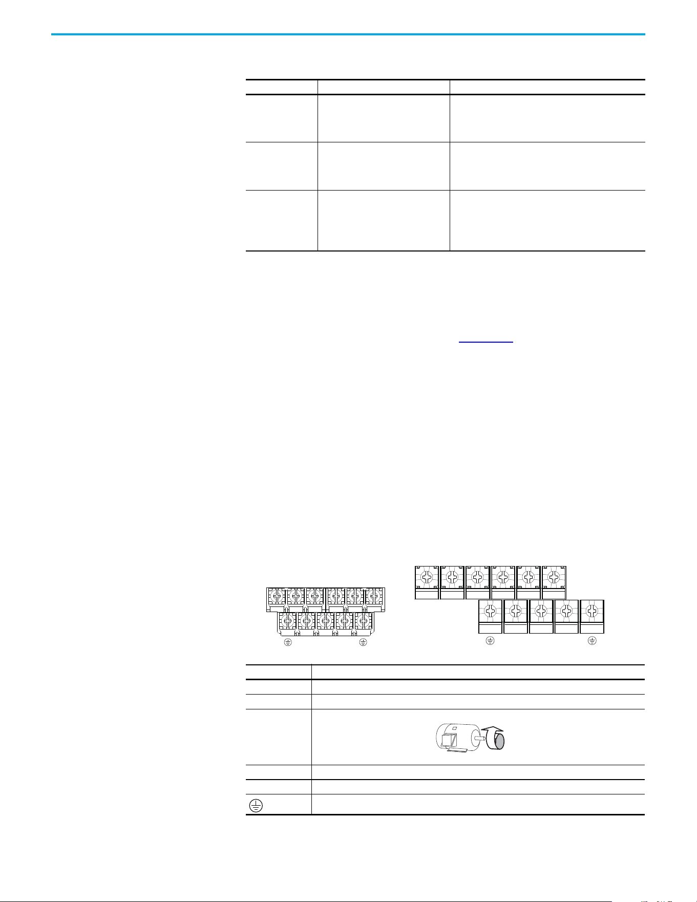
Rockwell Automation Publication 520-UM002E-EN-E - September 2024 31
Chapter 1 Installation/Wiring
Reflected Wave Protection
The drive should be installed as close to the motor as possible. Installations with long motor cables
may require the addition of external devices to limit voltage reflections at the motor (reflected
wave phenomena). See Reflected Wave in the Wiring and Grounding for Pulse Width Modulated
(PWM) AC Drives Installation Instructions, publication DRIVES-IN001
.
The reflected wave data applies to all carrier frequencies 2…8 kHz.
Note: For 240V ratings and lower, reflected wave effects do not need to be considered.
Output Disconnect
The drive is intended to be commanded by motion commands that will start and stop the motor. A
device that routinely disconnects then reapplies output power to the motor for starting and
stopping the motor should not be used. If it is necessary to disconnect power to the motor with the
drive outputting power, use the Logix Designer application to disable the drive (Aux Fault or Coast
to Stop).
Power Terminal Block Power Terminal Block
Recommended Shielded Wire
Location Rating/Type Description
Standard (Option 1)
600V, 90 °C (194 °F) XHHW2/RHW-2
Anixter B209500-B209507, Belden
29501-29507, or equivalent
• Four tinned copper conductors with XLPE insulation
• Copper braid/aluminum foil combination shield and
tinned copper drain wire
•PVC jacket
Standard (Option 2)
Tray rated 600V, 90 °C (194 °F)
RHH/RHW-2 Anixter OLF-7xxxxx or
equivalent
• Three tinned copper conductors with XLPE insulation
• 5 mil single helical copper tape (25% overlap min.) with
three bare copper grounds in contact with shield
•PVC jacket
Class I and II;
Division I and II
Tray rated 600V, 90 °C (194 °F)
RHH/RHW-2 Anixter 7V-7xxxx-3G or
equivalent
• Three bare copper conductors with XLPE insulation and
impervious corrugated continuously welded aluminum
armor
• Black sunlight resistant PVC jacket overall
• Three copper grounds on 6 mm
2
(10 AWG) and smaller
Terminal Description
R/L1, S/L2 1-phase Input Line Voltage Connection
R/L1, S/L2, T/L3 3-phase Input Line Voltage Connection
U/T1, V/T2, W/T3 Motor Phase Connection =
Switch any two motor leads to change
forward direction or change the Motion
Polarity within Studio 5000 Logix
Designer application > Axis Properties >
Polarity category.
DC+, DC- DC Bus Connection
BR+, BR- Dynamic Brake Resistor Connection
Safety Ground - PE
V/T2T/L3S/L2R/L1 U/T1 W/T3
V/T2T/L3S/L2R/L1 U/T1 W/T3
BR+
BR-
DC- DC+
BR+
BR-
DC-
DC+
Frame A, B, C & D Frame E
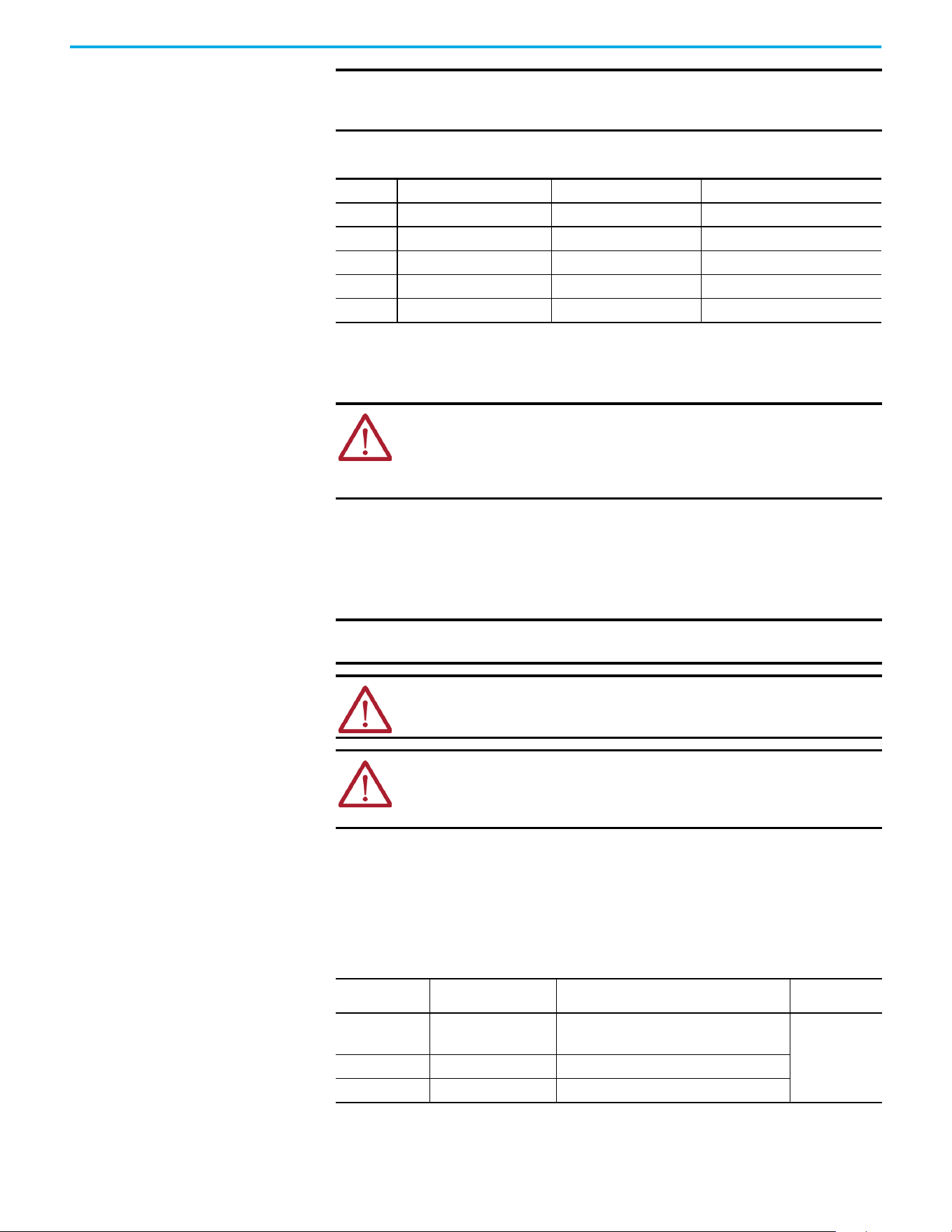
32 Rockwell Automation Publication 520-UM002E-EN-E - September 2024
Chapter 1 Installation/Wiring
I/O Wiring Motor Start/Stop Precautions
Important points to remember about I/O wiring:
• Always use copper wire.
• Wire with an insulation rating of 600V or greater is recommended.
• Control and signal wires should be separated from power wires by at least 0.3 m (1 ft).
Signal and Control Wire Types
Recommendations are for 50 °C (122 °F) ambient temperature.
75 °C (167 °F) wire must be used for 60 °C (140 °F) ambient temperature.
90 °C (194 °F) wire must be used for 70 °C (158 °F) ambient temperature.
IMPORTANT Terminal screws may become loose during shipment. Verify that all terminal
screws are tightened to the recommended torque before applying power to
the drive.
Power Terminal Block Wire Specifications
Frame
Maximum Wire Size
(1)
(1) Maximum/minimum sizes that the terminal block will accept. These are not recommendations.
Minimum Wire Size
(1)
Torque
A
5.3 mm
2
(10 AWG) 0.8 mm
2
(18 AWG)
1.76…2.16 N•m (15.6…19.1 lb•in)
B
8.4 mm
2
(8 AWG) 2.1 mm
2
(14 AWG)
1.76…2.16 N•m (15.6…19.1 lb•in)
C
8.4 mm
2
(8 AWG) 2.1 mm
2
(14 AWG)
1.76…2.16 N•m (15.6…19.1 lb•in)
D
13.3 mm
2
(6 AWG) 5.3 mm
2
(10 AWG)
1.76…2.16 N•m (15.6…19.1 lb•in)
E
26.7 mm
2
(3 AWG) 8.4 mm
2
(8 AWG)
3.09…3.77 N•m (27.3…33.4 lb•in)
ATTENTION: A contactor or other device that routinely disconnects and
reapplies the AC line to the drive to start and stop the motor can cause drive
hardware damage. The drive is designed to use control input signals that will
start and stop the motor. If used, the input device must not exceed one
operation per minute or drive damage can occur.
IMPORTANT I/O terminals labeled “Common” are not referenced to the safety ground (PE)
terminal and are designed to greatly reduce common mode interference.
ATTENTION: Driving the 4…20 mA analog input from a voltage source could
cause component damage. Verify proper configuration before applying input
signals.
ATTENTION: Due to its control circuitry difference from the PowerFlex 523 and
PowerFlex 525 drives, connecting Terminals 01 and 11 on the PowerFlex 527
drive causes an internal short and results in some internal components
incurring damage to the control module I/O circuitry.
Recommended Signal Wire
Signal Type/
Where Used
Belden Wire Types
(1)
(or equivalent)
(1) Stranded or solid wire
Description Min. Insulation
Rating
Analog I/O 8760/9460
0.750 mm
2
(18 AWG), twisted pair,
100% shield with drain
(2)
(2) If the wires are short and contained within a cabinet, which has no sensitive circuits, the use of shielded wire may not be necessary,
but is always recommended.
300V,
60 °C
(140 °F)
Remote Pot 8770
0.750 mm
2
(18 AWG), 3 conductor, shielded
Encoder 9728/9730
0.196 mm
2
(24 AWG), individually shielded pairs

Rockwell Automation Publication 520-UM002E-EN-E - September 2024 33
Chapter 1 Installation/Wiring
Maximum Control Wire Recommendations
Do not exceed control wiring length of 30 m (100 ft). Control signal cable length is highly dependent
on electrical environment and installation practices. To improve noise immunity, the I/O terminal
block Common may be connected to ground terminal/protective earth.
Control I/O Terminal Block
Recommended Control Wire for Digital I/O
Type Wire Types Description Min. Insulation
Rating
Unshielded
Per US NEC or applicable
national or local code
–
300V,
60 °C
(140 °F)
Shielded
Multi-conductor shielded
cable such as Belden 8770
(or equivalent)
0.750 mm
2
(18 AWG), 3 conductor, shielded
Control I/O Terminal Block Wire Specifications
Frame
Maximum Wire Size
(1)
(1) Maximum/minimum sizes that the terminal block will accept. These are not recommendations.
Minimum Wire Size
(1)
Torque
A…E
1.3 mm
2
(16 AWG) 0.13 mm
2
(26 AWG)
0.71…0.86 N•m (6.2…7.6 lb•in)
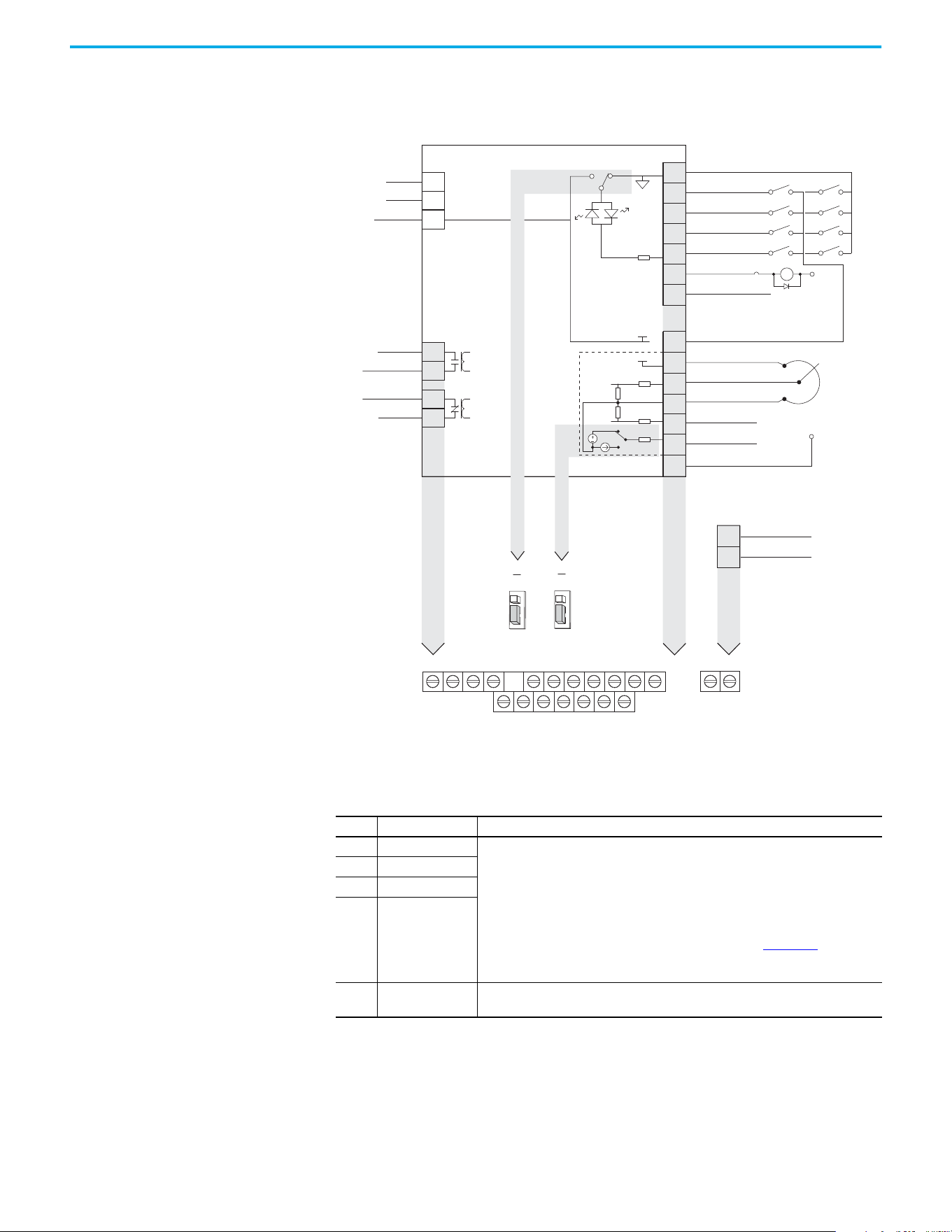
34 Rockwell Automation Publication 520-UM002E-EN-E - September 2024
Chapter 1 Installation/Wiring
PowerFlex 527 Control I/O Removable Terminal Block
PowerFlex 527 Control I/O Wiring Block Diagram
(1) When using an opto output with an inductive load such as a relay, install a recovery diode parallel to the relay as shown, to help
prevent damage to the output.
(2) Do not short across Terminals 01 and 11.
Control I/O Terminal Designations
No. Signal Description
R1 Relay 1 N.O. These are the Normally Open (N.O.), Common, and Normally Closed (N.C.) contacts for the
programmable relay output.
Resistive: 1.0 A @ 30V DC/ 0.2 A @ 125V AC/ 0.1 A @ 230V AC
Inductive: 0.5 A @ 30V DC/0.1 A @ 125V AC/ 0.1 A @ 230V AC
Rated minimum current is 5 mA or less @ 24V DC.
Note: These are general-purpose outputs and do not have the same functionality as
system outputs when compared to chassis or remote I/O products. See the Logix 5000®
Controllers General Instructions Reference Manual, publication 1756-RM003
, for
important information regarding execution conditions and action that is taken for the
respective instructions used to control the digital outputs on the drive.
R2 Relay 1 Common
R5 Relay 2 Common
R6 Relay 2 N.C.
01 Digital Common
The return for digital I/O. It is electrically isolated (along with the digital I/O) from the rest
of the drive, except for the communications port.
R1
11
(2)
12 13 14 15 16 17
R2 R5 R6 01
(2)
02 03 04 05 06 07
C1 C2
04
05
06
07
01
02
03
11
12
13
14
15
16
17
Digital Common
Digital In 1
Digital In 2
Digital In 3
Digital In 4
R1
R2
S1
S2
S+
Relay 1 N.O.
Relay 1 Common
+24V DC
+10V DC
±10V Input
Analog Common
4-20mA Input
Analog Output
Opto Output 1
(1)
Opto Output 2
(1)
Ethernet
Comm Common
Opto Common
+24V
+10V
Safety 1
Safety 2
Safety +24V
Typical
SNK wiring
Typical
SRC wiring
Pot must be
1...10 k ohm
2 W min.
0-10V
0/4-20 mA
SNK
Digital In
Analog Out
J2
J1
SRC
ACO
AVO
SRC
SNK
R5
R6
Relay 2 Common
Relay 2 N.C.
C1
C2
Common
(1)
24V
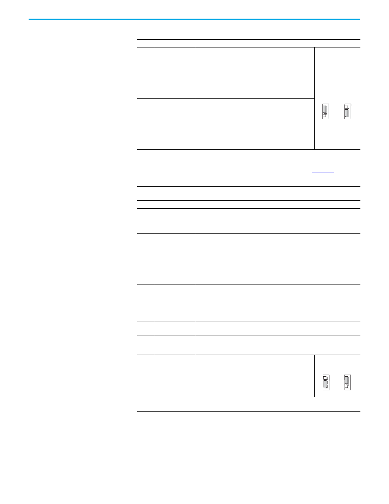
Rockwell Automation Publication 520-UM002E-EN-E - September 2024 35
Chapter 1 Installation/Wiring
02 Digital In 1
Configurable to Home, Registration 1, Drive Enable, Positive
Overtravel, and Negative Overtravel.
If programmed as unassigned, this becomes a general-
purpose input.
Set the Digital In
jumper (J1) as shown.
03 Digital In 2
Configurable to Registration 2, Drive Enable, Positive Overtravel,
and Negative Overtravel.
If programmed as unassigned, this becomes a general-
purpose input.
04 Digital In 3
Configurable to Drive Enable, Positive Overtravel, and Negative
Overtravel.
If programmed as unassigned, this becomes a general-
purpose input.
05 Digital In 4
Configurable to Drive Enable, Positive Overtravel, and Negative
Overtravel.
If programmed as unassigned, this becomes a general-
purpose input.
06 Opto Output 1 Programmable digital output.
These are general-purpose outputs and do not have the same functionality as system
outputs when compared to chassis or remote I/O products. See the Logix 5000
Controllers General Instructions Reference Manual, publication 1756-RM003
, for
important information regarding execution conditions and action that is taken for the
respective instructions used to control the digital outputs on the drive.
07 Opto Output 2
C1 Ethernet
This terminal is tied to the Ethernet port shield. Tie this terminal to a clean ground in
order to improve noise immunity when using external communication peripherals.
C2 Comm Common This is the signal common for the communication signals.
S1 Safety 1 Safety input 1
S2 Safety 2 Safety input 2
S+ Safety +24V +24V supply for safety circuit. This is internally tied to the +24V DC source (Pin-11).
11 +24V DC
+24V DC (+/-10%) supply for digital inputs. It is rated to supply at least 100 mA and will
use Digital Common as the return. It will also be short-circuit protected (not damaged if
tied to a Common or GND), for a short duration, and will not be damaged if connected to
the +24V DC source of a different drive.
12 +10V DC
+10V DC (-0% / +6%) supply for potentiometer or 0-10V input. It is rated to supply at
least 15 mA and will use Analog Common as the return. It will also be short-circuit
protected (not damaged if tied to a Common or GND) and will not be damaged if
connected to the +10V DC source of a different drive.
13 ±10V In
±10V bipolar analog input optically isolated from the drive to avoid ground loops. This
input has approximately 100 kΩ input impedance. If a remote potentiometer is used
with this input the maximum pot impedance is 10 kΩ and the minimum impedance and
the maximum is still 10 kΩ. The A/D resolution will be 10-bit or better. The drive will not
be damaged if up to ±27V DC or voltage surge up to 1 kV is applied to this port. The input
bandwidth shall be about 100 Hz.
14 Analog Common
This is the return for the analog I/O. It is electrically isolated (along with the analog I/O)
from the rest of the drive.
15 4…20 mA In
4-20 mA analog input optically isolated from the drive to allow daisy chain
configurations and to avoid ground loops. The input impedance for the 4…20 mA analog
input is approximately 250 Ω. The A/D resolution will be 10-bit or better.
16 Analog Output
Configurable to a 0…20 mA or 0…10V analog output signal. Set
the Analog Out jumper (J2) as shown, then set the ACO/AVO
attribute. See Setting the ACO/AVO Attribute on page 156
for
instructions.
17 Opto Common
The emitters of the Optocoupler Outputs (1 and 2) are tied together at Optocoupler
Common. They are therefore electrically isolated from the rest of the drive.
Control I/O Terminal Designations (Continued)
No. Signal Description
SNK
Digital In
J1
SRC
SNK
Digital In
J1
SRC
Sink Source
Analog Out
J2
ACO
AVO
Analog Out
J2
ACO
AVO
0…10V 0…20 mA
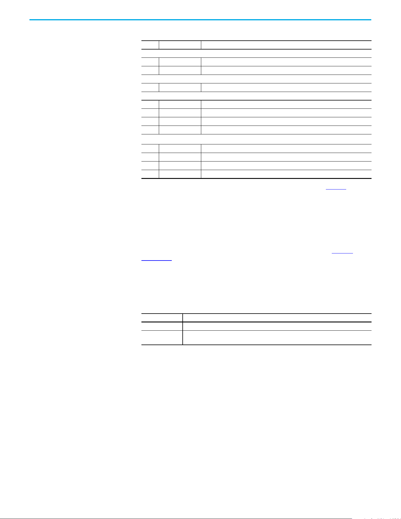
36 Rockwell Automation Publication 520-UM002E-EN-E - September 2024
Chapter 1 Installation/Wiring
CE Conformity Compliance with the Low Voltage Directive and Electromagnetic Compatibility Directive has been
demonstrated using harmonized European Norm (EN) standards that are published in the Official
Journal of the European Communities. PowerFlex 520-series drives comply with the EN standards
that are listed below when installed according to the installation instructions in this manual.
Product certifications and Declarations of Conformity (DoC) are available online at rok.auto/
certifications.
Low Voltage Directive (2014/35/EU)
• EN 61800-5-1 Adjustable speed electrical power drive systems – Part 5-1: Safety
requirements – Electrical, thermal, and energy.
EMC Directive (2014/30/EU)
• EN 61800-3 – Adjustable speed electrical power drive systems - Part 3: EMC requirements
and specific test methods.
Machinery Directive (2006/42/EC)
• EN ISO 13849-1 – Safety of machinery – Safety-related parts of control systems -Part 1:
General principles for design.
• EN 61800-5-2 – Adjustable speed electrical power drive systems - Part 5-2: Safety
requirement – Functional.
• EN 62061 – Safety of machinery – Functional safety of safety-related electrical, electronic,
and programmable electronic control systems.
• EN 60204-1 – Safety of machinery – Electrical equipment of machines - Part 1: General
requirements.
• EN 61508 Part 1-7 Functional safety of electrical/electronic/programmable electronic safety-
related systems – Parts 1-7.
Tag Attributes in Logix Designer for Inputs and Outputs
No. Signal Tag Attribute
Analog Input
13 ±10V In <axis tag>.AnalogInput1
15 4…20 mA In <axis tag>.AnalogInput2
Analog Output
16 Analog Output <axis tag>.AnalogOutput1
Digital Input
02 Digital In 1 <axis tag>.DigitalInput0
03 Digital In 2 <axis tag>.DigitalInput1
04 Digital In 3 <axis tag>.DigitalInput2
05 Digital In 4 <axis tag>.DigitalInput3
Digital Output
(1)
06 Opto Output 1 <axis tag>.DigitalOutput0
07 Opto Output 2 <axis tag>.DigitalOutput1
R1 Relay 1 N.O. <axis tag>.DigitalOutput2
R6 Relay 2 N.C. <axis tag>.DigitalOutput3
(1) These are general-purpose outputs and do not have the same functionality as system outputs when compared to chassis or
remote I/O products. See the Logix 5000 Controllers General Instructions Reference Manual, publication 1756-RM003, for important
information regarding execution conditions and action that is taken for the respective instructions used to control the digital
outputs on the drive.
Pollution Degree Ratings According to EN 61800-5-1
Pollution Degree Description
1 No pollution or only dry, non-conductive pollution occurs. The pollution has no influence.
2
Normally, only non-conductive pollution occurs. Occasionally, however, a temporary conductivity
caused by condensation is to be expected, when the drive is out of operation.

Rockwell Automation Publication 520-UM002E-EN-E - September 2024 37
Chapter 1 Installation/Wiring
ATEX Directive (2014/34/EU)
• EN 50495 – Safety devices that are required for the safe functioning of equipment with
respect to explosion risks.
UKCA Conformity Compliance with application Statutory Regulations has been demonstrated using harmonized
standards published in the UK list of Designated standards. PowerFlex 520-series drives comply
with the EN standards listed below when installed according to the installation instructions in this
manual.
UK Declarations of Conformity are available online at rok.auto/certifications
.
Electrical Equipment (Safety) Regulations (2016 No. 1101)
• EN 61800-5-1 Adjustable speed electrical power drive systems – Part 5-1: Safety
requirements – Electrical, thermal, and energy.
Electromagnetic Compatibility Regulations (2016 No. 1091)
• EN 61800-3 Adjustable speed electrical power drive systems – Part 3: EMC requirements
and specific test methods.
Supply of Machinery (Safety) Regulations (2008 No. 1597)
• EN ISO 13849-1 – Safety of machinery – Safety related parts of control systems -Part 1:
General principles for design.
• EN 61800-5-2 – Adjustable speed electrical power drive systems – Part 5-2: Safety
requirement – Functional.
• EN 62061 – Safety of machinery – Functional safety of safety-related electrical, electronic,
and programmable electronic control systems.
• EN 60204-1 – Safety of machinery – Electrical equipment of machines – Part 1: General
requirements.
• EN 61508 Part 1-7 Functional safety of electrical, electronic, and programmable electronic
safety-related systems – Part 1-7.
Equipment and Protective Systems Intended for Use in Potentially
Explosive Atmospheres Regulations (2016 No. 1107)
• EN 50495 – Safety devices required for the safe functioning of equipment with respect to
explosion risks.
General Considerations
• For CE and UK compliance, drives must satisfy installation requirements that are related to
both EN 61800-5-1 and EN 61800-3 provided in this document.
• PowerFlex 520-series drives must be installed in a pollution degree 1 or 2 environment to be
compliant with the CE LV Directive and UK LV Regulations. See Pollution Degree Ratings
According to EN 61800-5-1 on page 36 for descriptions of each pollution degree rating.
• PowerFlex 520-series drives comply with the EMC requirements of EN 61800-3 when
installed according to good EMC practices and the instructions that are provided in this
document. However, many factors can influence the EMC compliance of an entire machine
or installation, and compliance of the drive itself does not ensure compliance of all
applications.
Pollution Degree Ratings According to EN 61800-5-1
Pollution
Degree
Description
1 No pollution or only dry, non-conductive pollution occurs. The pollution has no influence.
2
Normally, only non-conductive pollution occurs. Occasionally, however, a temporary conductivity that is
caused by condensation is to be expected, when the drive is out of operation.
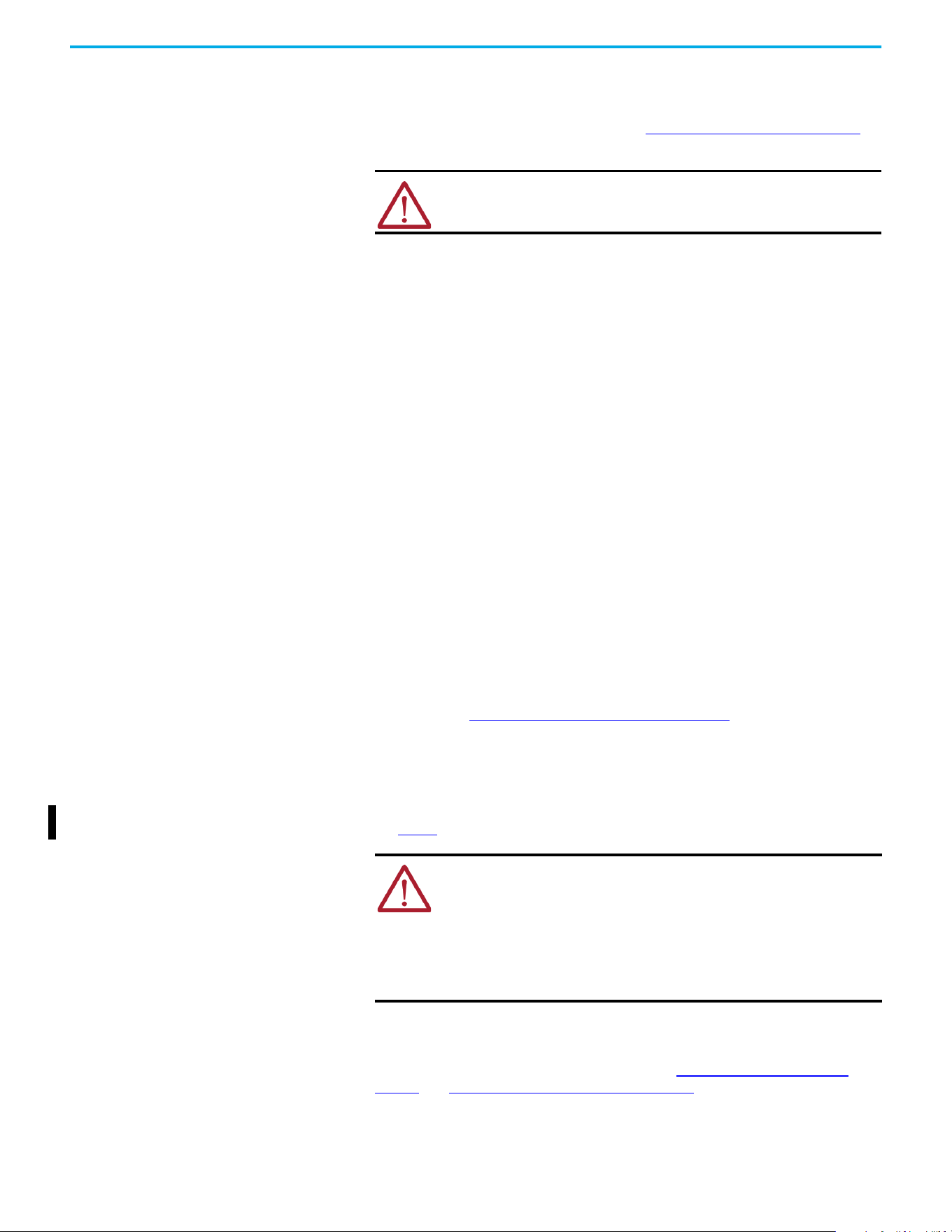
38 Rockwell Automation Publication 520-UM002E-EN-E - September 2024
Chapter 1 Installation/Wiring
• PowerFlex 520-series drives are not intended to be used on public low-voltage networks
that supply domestic premises. Without additional mitigation, radio frequency interference
is expected if used on such a network. The installer is responsible for taking measures such
as a supplementary line filter and enclosure (see Connections and Grounding on page 39
) to
prevent interference, in addition to the installation requirements of this document.
• PowerFlex 520-series drives generate harmonic current emissions on the AC supply
system. When operated on a public low-voltage network it is the responsibility of the
installer or user to verify that applicable requirements of the distribution network operator
have been met. Consultation with the network operator and Rockwell Automation may be
necessary.
• If the optional NEMA 1 kit is not installed, the drive must be installed in an enclosure with side
openings less than 12.5 mm (0.5 in.) and top openings less than 1.0 mm (0.04 in.) to maintain
compliance with the LV Directive and UK LV Regulations.
• The motor cable should be kept as short as possible to avoid electromagnetic emission and
capacitive currents.
• Use of line filters in ungrounded systems is not recommended.
• In CE and UK installations, input power must be a Balanced wye with Center Ground
configuration for EMC compliance.
• If the DC Bus terminals or the Dynamic Brake terminals are used, the drive must be installed
in an enclosure and fuses must be used for input protection. The ventilated enclosure needs
to be IP20 rating or higher and at least 1.5x size larger than the drive.
Installation Requirements Related to EN 61800-5-1 and the Low Voltage Directive/UK LV
Regulations
• 600V PowerFlex 520-series drives can only be used on a “center grounded” supply system
for altitudes up to and including 2000 m (6,562 ft).
• When used at altitudes above 2000 m (6,562 ft) up to a maximum of 4800 m (15,748 ft),
PowerFlex 520-series drives of voltage classes up to 480V may not be powered from a
“corner-earthed” supply system to maintain compliance with the CE LV Directive and UK LV
Regulations. See Derating Guidelines for High Altitude on page 15
.
• PowerFlex 520-series drives produce leakage current in the protective earthing conductor,
which exceeds 3.5 mA AC and/or 10 mA DC. The minimum size of the protective earthing
(grounding) conductor that is used in the application must comply with local safety
regulations for high protective earthing conductor current equipment.
• When connected, power terminals DC+/BR+, DC-, and BR- must be protected with a DC fuse.
See Table 3
for fuse part numbers of the fuses.
Installation Requirements Related to EN 61800-3 and the EMC Directive and UK EMC
Regulations
• The drive must be earthed (grounded) as described in Connections and Grounding on
page 39. See General Grounding Requirements on page 18 for additional grounding
recommendations.
• Output power wiring to the motor must employ cables with a braided shield providing 75%
or greater coverage, or the cables must be housed in metal conduit, or equivalent shield
ATTENTION: NEMA/UL Open Type drives must either be installed in a
supplementary enclosure or equipped with a “NEMA Type 1 Kit” to be CE
and UK compliant with respect to protection against electrical shock.
ATTENTION: PowerFlex 520-series drives produce DC current in the
protective earthing conductor which may reduce the ability of residual
current-operated protective devices (RCD) or residual current-operated
monitoring devices (RCM) of type A or AC to provide protection for other
equipment in the installation.
Where an RCD or RCM is used for protection in case of direct or indirect
contact, only an RCD or RCM of Type B is allowed on the supply side of
this product.
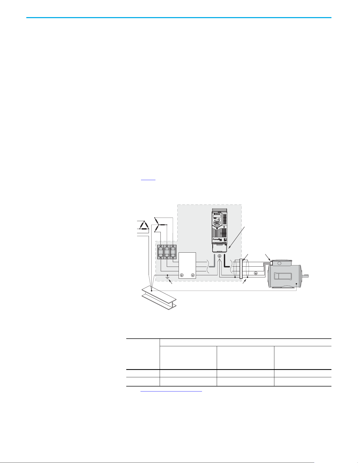
Rockwell Automation Publication 520-UM002E-EN-E - September 2024 39
Chapter 1 Installation/Wiring
must be provided. Continuous shielding must be provided from the drive enclosure to the
motor enclosure. Both ends of the motor cable shield (or conduit) must terminate with a
low-impedance connection to earth.
Drive Frames A...E: At the drive end of the motor, either
a. The cable shield must be clamped to a properly installed “EMC Plate” for the drive, kit
number 25-EMC1-Fx.
or
b. The cable shield or conduit must terminate in a shielded connector that is installed in an
EMC plate, conduit box, or similar.
• At the motor end, the motor cable shield or conduit must terminate in a shielded connector,
which must be properly installed in an earthed motor wiring box that is attached to the
motor. The motor wiring box cover must be installed and earthed.
• All control (I/O) and signal wiring to the drive must use cable with a braided shield providing
75% or greater coverage, or the cables must be housed in metal conduit, or equivalent
shielding must be provided. When shielded cable is used, the cable shield should be
terminated with a low impedance connection to earth at only one end of the cable,
preferably the end where the receiver is located. When the cable shield is terminated at the
drive end, it may be terminated either by using a shielded connector in conjunction with a
conduit plate or conduit box, or the shield may be clamped to an “EMC plate.”
• Motor cabling must be separated from control and signal wiring wherever possible.
• Maximum motor cable length must not exceed the maximum length that is indicated in
Table 3
for compliance with radio frequency emission limits for the specific standard and
installation environment.
Connections and Grounding
(1) Some installations require a shielded enclosure. Keep wire length as short as possible between the enclosure entry point and the
EMI filter.
Table 3 - PowerFlex 527 RF Emission Compliance and Installation Requirements
Filter Type Standard/Limits
EN61800-3 Category C1
EN61000-6-3
CISPR11 Group 1 Class B
EN61800-3 Category C2
EN61000-6-4
CISPR11 Group 1 Class A
(Input power ≤ 20 kVA)
EN61800-3 Category C3
(I ≤ 100 A)
CISPR11 Group 1 Class A
(Input power > 20 kVA)
Internal – 10 m (33 ft) 20 m (66 ft)
External
(1)
(1) See Accessories and Dimensions on page 131 for more information on optional external filters.
30 m (16 ft) 100 m (328 ft) 100 m (328 ft)
R/L1
S/L2
T/L3
U/T1
V/T2
W/T3
EMI ttings and metal conduit
IP 30/NEMA 1/UL Type 1
option kit or EMC kit
Shielded enclosure
(1)
Building structure steel
Enclosure ground connection
EMI lter
L1'
L2'
L3'
L1
L2
L3
Shielded motor cable

40 Rockwell Automation Publication 520-UM002E-EN-E - September 2024
Chapter 1 Installation/Wiring
Additional Installation Requirements
This section provides information on additional requirements for Class C1 and C2 installation, such
as enclosures and EMC cores.
IMPORTANT EMC cores are included with:
• Drives that have an internal EMC filter (25x-xxxxN114)
• External EMC filter accessory kit (25-RFxxx)
IMPORTANT An enclosure, shielded input cable, and EMC cores are not required to meet
Class C3 requirements.
Additional Installation Requirements
Frame
Size
Class C1 Class C2
Enclosure Conduit or Shielded
Cable @ Input
EMC Cores Required
(Included with product)
Enclosure Conduit or Shielded
Cable @ Input
EMC Cores Required
(Included with product)
100...120V AC (-15%, +10%) – 1-phase Input with External EMC Filter, 0...120V 1-phase Output
ANoNo No NoNo No
BNoNo No NoNo No
200...240V AC (-15%, +10%) – 1-phase Input with External EMC Filter, 0...230V 3-phase Output
A Yes Yes No No No Input/Output
B Yes Yes Output only No No Input/Output
200...240V AC (-15%, +10%) – 1-phase Input with Internal EMC Filter, 0...230V 3-phase Output
(1)
A* * * Yes No No
B* * * Yes No No
200...240V AC (-15%, +10%) – 3-phase Input with External EMC Filter, 0...230V 3-phase Output
A Yes Yes Output only No No Input/Output
B Yes Yes Output only No No Input/Output
C Yes Yes Output only No No Input/Output
D Yes Yes No No No Input only
E Yes Yes Output only No No Input only
380...480V AC (-15%, +10%) – 3-phase Input with External EMC Filter, 0...460V 3-phase Output
A Yes Yes No No No Input/Output
B Yes Yes No No No Input/Output
C Yes Yes No No No Input only
D Yes Yes Output only No No Input/Output
E Yes Yes No Yes No Input/Output
380...480V AC (-15%, +10%) – 3-phase Input with Internal EMC Filter, 0...460V 3-phase Output
(1)
A * * * No No Input/Output
B * * * No No Input/Output
C * * * No No Input/Output
D * * * No No Input/Output
E * * * No No Input/Output
525...600V AC (-15%, +10%) – 3-phase Input with External EMC Filter, 0...575V 3-phase Output
A Yes Yes No No No Input/Output
B Yes Yes No No No Input/Output
C Yes Yes No No No Input/Output
D Yes Yes No No No Input/Output
E Yes Yes No Yes No No
(1) An (*) indicates that EMC requirements are not met.
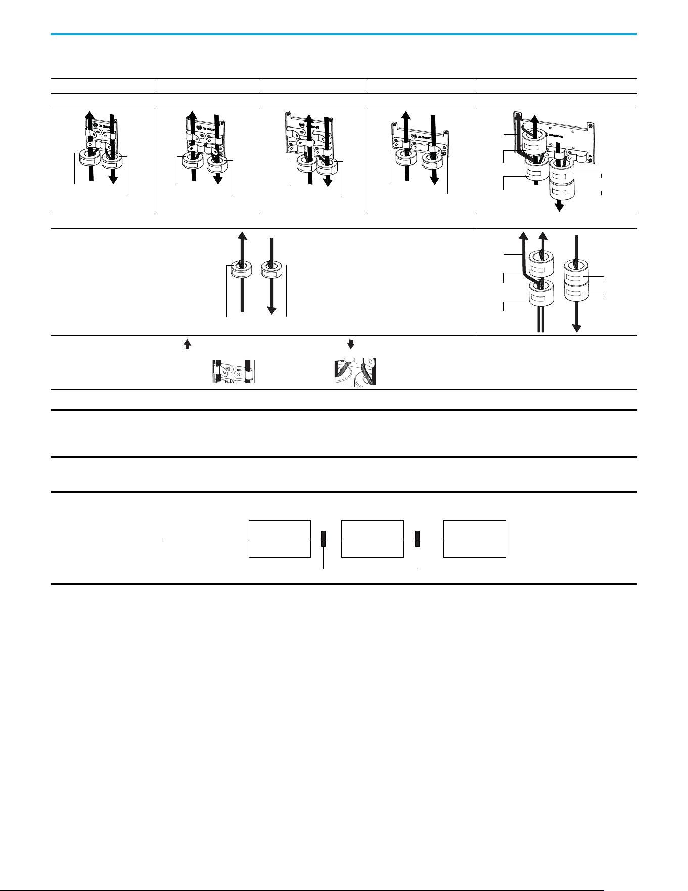
Rockwell Automation Publication 520-UM002E-EN-E - September 2024 41
Chapter 1 Installation/Wiring
Recommended Placement of EMC Cores with Optional EMC Plate
Frame A Frame B Frame C Frame D Frame E
With Optional EMC Plate (25-EMC-Fx)
Without EMC Plate
CORE-xx-A-1
CORE-xx-A-2
CORE-xx-B-1
CORE-xx-B-2
CORE-xx-C-1
CORE-xx-C-2
CORE-xx-D-1
CORE-xx-D-2
CORE-E-1
CORE-E-2
CORE-E-3
CORE-E-4
Ground
cable
CORE-xx-x-1 CORE-xx-x-2
CORE-E-1
CORE-E-2
CORE-E-3
CORE-E-4
Ground
cable
Shows contact to
shielded layer
Secure EMC core by
using cable/zip ties
Input cable to drive (Shielded or inshielded)
Output cable from drive (Shielded)
IMPORTANT The ground cable/shield for both input and output must pass through the EMC core, except for the following:
• Frame E drives with internal filters where the grounded input cable must not pass through EMC CORE-E-1.
• 600V drives with external filters where the grounded output cable must not pass through the EMC core.
Recommended Placement of EMC Cores Relative to External Filter
Input core Output core
Incoming power
EMC filter Drive Motor
All Frame Sizes

42 Rockwell Automation Publication 520-UM002E-EN-E - September 2024
Chapter 1 Installation/Wiring
Notes:
Rockwell Automation Publication 520-UM002E-EN-E - September 2024 43
Chapter
Chapter
Chapter 2
Start Up
This chapter describes how to start up the PowerFlex 527 drive.
Prepare for Drive Startup Before starting up the drive, it is recommended to perform the startup tasks described below to
achieve a smooth startup and drive operation. Verify that the drive is not powered (verify that DC
Bus voltage is less than 50V DC) before proceeding with the startup task list.
Drive Startup Task List
1. Disconnect and lock out power to the machine.
2. Verify that AC line power at the disconnect device is within the rated value of the drive.
3. If replacing a drive, verify the current catalog number of the drive. Verify all options installed
on the drive.
4. Verify that any digital control power is 24 volts.
5. Inspect grounding, wiring, connections, and environmental compatibility.
6. Verify that the Sink (SNK)/Source (SRC) jumper is set to match your control wiring scheme.
See the PowerFlex 527 Control I/O Wiring Block Diagram on page 34
for location.
7. Wire I/O as required for the application.
8. Wire the power input and output terminals.
9. Confirm that all inputs are connected to the correct terminals and are secure.
10. Collect and record motor nameplate and encoder or feedback device information. Verify
motor connections.
- Is the motor uncoupled?
- What direction will the motor need to turn for the application?
11. Verify the input voltage to the drive. Verify if the drive is on a grounded system. Verify that
the MOV jumpers are in the correct position. See AC Supply Source Considerations on
page 16 for more information.
12. Apply AC power to the drive.
- You need to establish a connection with a Logix controller and verify that the drive is
enabled using a Logix motion instruction (for example MSO command) and no “START
INHIBIT” condition exists. See Configuring the PowerFlex 527 Drive with Integrated Motion
on page 51 for instructions.
- Verify that the drive is receiving start and stop commands correctly.
- Verify that input currents are balanced.
- Verify that motor currents are balanced.
IMPORTANT Read General Precautions on page 10
before proceeding.
ATTENTION: Power must be applied to the drive to perform the following
startup procedures. Some of the voltages present are at incoming line potential.
To avoid electric shock hazard or damage to equipment, only qualified service
personnel should perform the following procedure. Thoroughly read and
understand the procedure before beginning. If an event does not occur while
performing this procedure, Do Not Proceed. Remove All Power including user
supplied control voltages. User supplied voltages may exist even when main AC
power is not applied to the drive. Correct the malfunction before continuing.
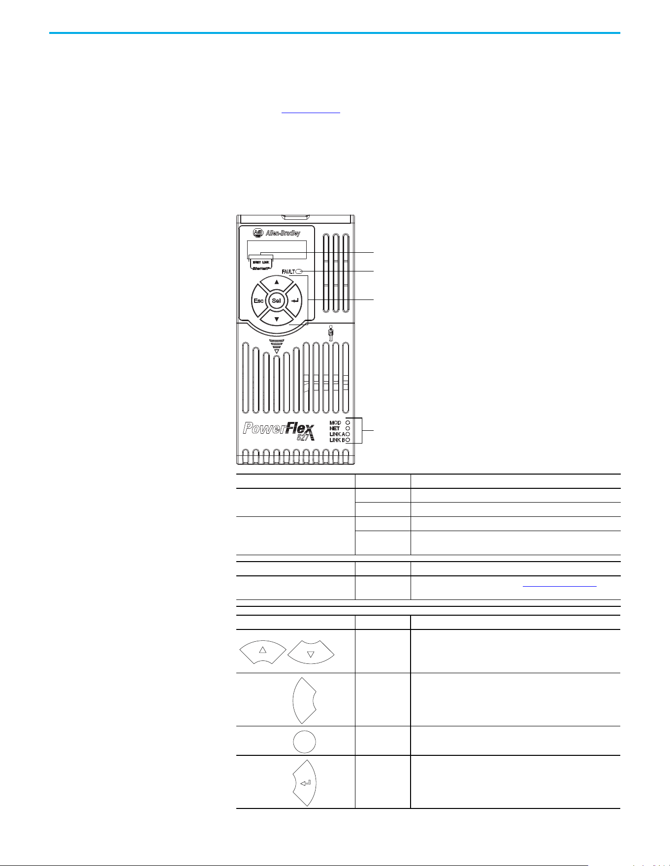
44 Rockwell Automation Publication 520-UM002E-EN-E - September 2024
Chapter 2 Start Up
Start, Stop, Direction, and Speed Control
Start, Stop, Direction, and Speed Control are done using Logix motion instructions, for example,
Motion Drive Start (MDS). See the Logix 5000 Controllers Motion Instructions Reference Manual,
publication MOTION-RM002 for more information.
Understanding the
PowerFlex 527 Display and
Indicators
The PowerFlex 527 drive has four status indicators, a fault indicator, an LCD display, and a
membrane keypad for navigation. The display is used to view information such as motor
information, axis states, faults, and set the network configuration. The indicators are used to
monitor the module and network status, and troubleshoot faults.
PowerFlex 527 Drive LCD Display and Status Indicators
Display Display State Description
ENET
Off Drive is not connected to the network.
Steady Drive is connected to the network.
LINK
Off Drive has not established a controller connection.
Steady
Drive is connected to the network and a controller connection
has been established.
LED LED State Description
FAULT Steady
Indicates that drive is faulted. See Fault Codes on page 111
for
more information.
Key Name Description
Up Arrow
Down Arrow
Pressing either arrow moves the selection to the next (or
previous) item. When changing values, pressing the Up arrow
increments the highlighted value. Values rollover after reaching
the end of the list.
Escape
Press to go back. Pressing enough times results in the HOME
screen.
Select Press to select a menu item.
Enter Press to confirm the selection and go to submenu items.
ENET and LINK display
Fault status indicator
Module status indicator
Network status indicator
Link A status indicator (Ethernet Port 1)
Link B status indicator (Ethernet Port 2)
Navigation keypad
Esc
Sel
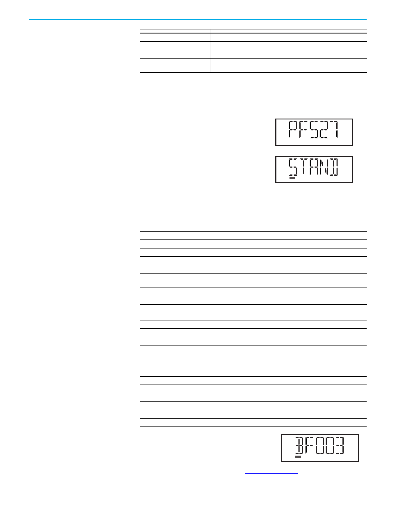
Rockwell Automation Publication 520-UM002E-EN-E - September 2024 45
Chapter 2 Start Up
For detailed descriptions of the Fault, MOD, NET, and LINK A/B status indicators, see PowerFlex 527
Drive Status Indicators on page 116.
Startup Sequence
On power-up, the drive will initialize and status
information will scroll across the LCD display.
After initialization, the Device/Axis state will be
shown on the LCD display. In this example, the
current state is STANDBY.
Device and Axis States
Table 4 and Table 5 list the possible Device and Axis states and their descriptions.
If a boot fault occurs during initialization, a fault number
shows up on the screen with the format, “BFxxx”, where
“BF” represents boot fault and “xxx” refers to the fault
code. In this example, fault BF003 is shown.
For a list of other types of possible faults, see Fault Codes on page 111
.
LED LED State Description
MOD Steady Green Drive is operational and no fault exists.
NET Steady Green Drive is online and has connections in the established state.
LINK A (Ethernet Port 1)
LINK B (Ethernet Port 2)
Steady Green Drive is connected to the network but not transmitting data.
Table 4 - Device States
Device State Description
STANDBY The drive is waiting to receive configuration information from the controller.
CONNECTING The drive is trying to establish communication with the EtherNet/IP controller.
CONFIGURING The drive is receiving configuration information from the controller.
SYNCING The drive is waiting for a successful Group Sync service.
CONN_TIMEOUT
The drive is trying to establish communication with the EtherNet/IP controller but the
connection has timed out.
DUPLICATE_IP The drive has detected another device on the network with the same IP address.
FWUPDATE The drive is updating the firmware.
Table 5 - Axis States
Axis State Description
INITIALIZING The drive is initializing the motion connection.
PRECHARGE The drive is ready for mains input power.
STOPPED The drive is in the Stopped state and awaiting a motion command.
STARTING
The drive has received a motion command and is transitioning to the Running state
from the Stopped state.
RUNNING The drive is enabled and/or running.
TESTING The drive is actively executing a test procedure, for example, a hookup test.
STOPPING The drive is decelerating to a stop as the result of a disable.
ABORTING The drive is decelerating to a stop as the result of a fault or an abort request.
MAJOR FAULTED The drive is faulted due to an existing or past fault condition.
START INHIBITED The drive has an active condition that inhibits it from being enabled.
SHUTDOWN The drive has been shut down.
VOLTS
AMPS
HERTZ
RUN
FWD
REV
PROGRAM
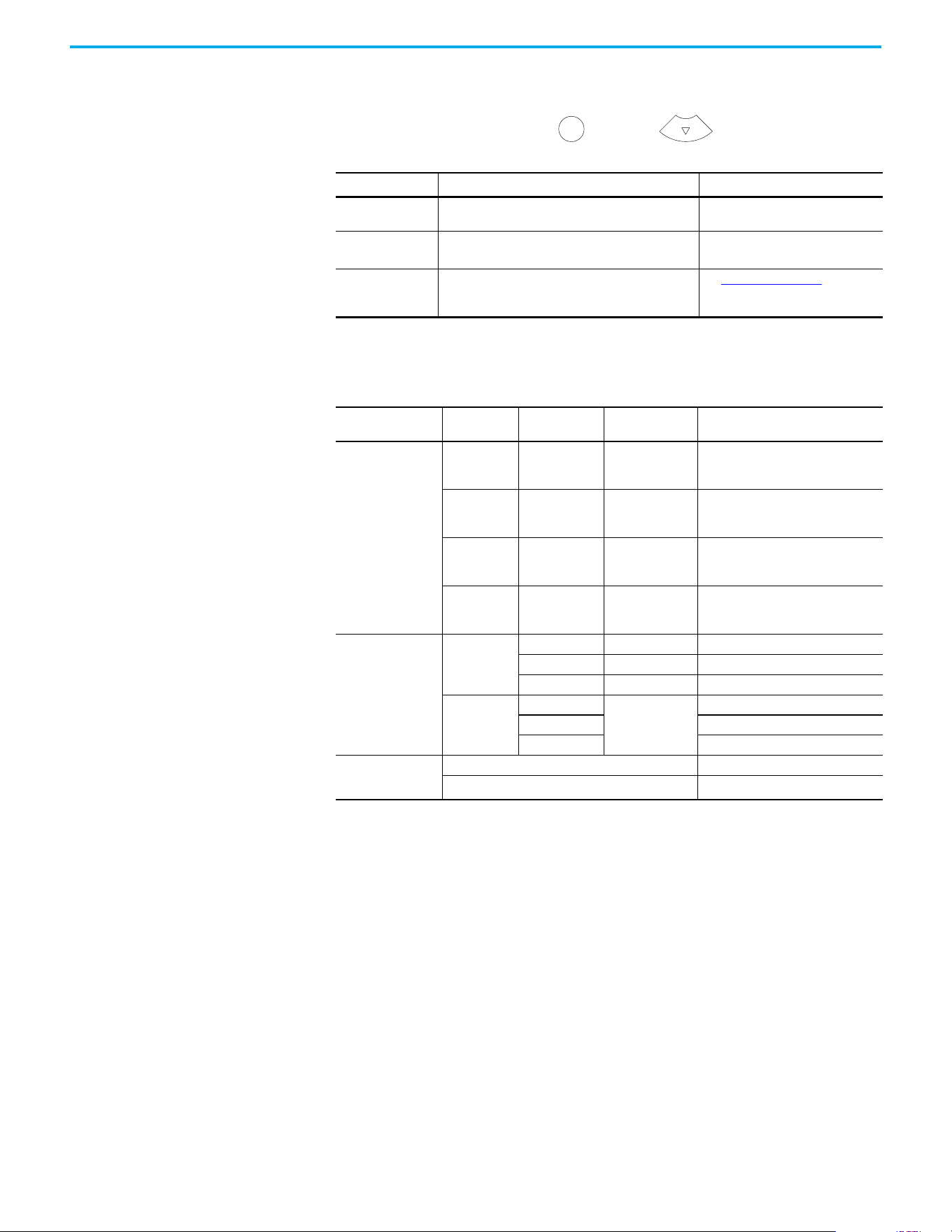
46 Rockwell Automation Publication 520-UM002E-EN-E - September 2024
Chapter 2 Start Up
Information Display
From the axis state screen, press Select or the Down arrow to access the following
information menu:
Network Configuration
Through the settings option, you can configure the drive IP address. There are two methods for
configuring the drive IP address:
• Static IP – Use Static IP when you want to manually configure the IP address, subnet mask,
and gateway addresses.
• DHCP (Dynamic Host Configuration Protocol) – Use DHCP when you want convenience
and ease-of-use compared to Static IP. The IP address, subnet mask, and gateway
addresses will be assigned automatically by the DHCP server.
Screen Option Description
Example Display
(1)
(1) The LCD only accommodates up to five characters. Text strings that are more than five characters are scrolled.
Version Info
Provides information on the hardware and software
versions.
HW Ver 01.002 FW Ver 01.102
Device Info
Provides information on the drive type, network
configuration, and IP address.
PowerFlex 527 Static IP 192.168.1.180
or PowerFlex 527 DHCP 192.168.1.180
(2)
(2) If “0.0.0.0” is displayed and DHCP is enabled, it means that the IP address has not been assigned by the DHCP server. Check your
network settings.
Settings
Allows configuration of network settings, changing the
display language, and resetting the drive.
See Network Configuration for
instructions on how to configure the IP
address.
Navigating the Settings Menu
Settings Menu
Selections
Sub Menu
Selections
Attributes Default Description
Protected Mode
(1)
(1) This setting is only available in PowerFlex 527 firmware revision 2.001 or later.
Reset
ENABLED
DISABLED
ENABLED
When Enabled (default), identity object
resets are not possible when a
controller connection is open.
Network Config
ENABLED
DISABLED
ENABLED
When Enabled (default), network
configuration changes are not possible
when a controller connection is open.
Flash Update
ENABLED
DISABLED
ENABLED
When Enabled (default), firmware
updates are not possible when a
controller connection is open.
Device Config
ENABLED
DISABLED
ENABLED
When Enabled (default), only attribute
writes are possible when a controller
connection is open.
Network
Static IP
IP address 192.168.1.180 Indicates current IP address.
Subnet mask 255.255.255.0 Indicates current subnet mask.
Gateway 192.168.1.1 Indicates current gateway.
DHCP
IP address
Automatically
assigned by the
DHCP server.
Indicates current IP address.
Subnet mask Indicates current subnet mask.
Gateway Indicates current gateway.
Web
(1)
Enabled Enables the web server.
->Disabled
(2)
(2) An arrow (->) appears in front of the chosen attribute indicating that this attribute is currently configured. This is also the factory
default setting.
Disables the web server.
Sel
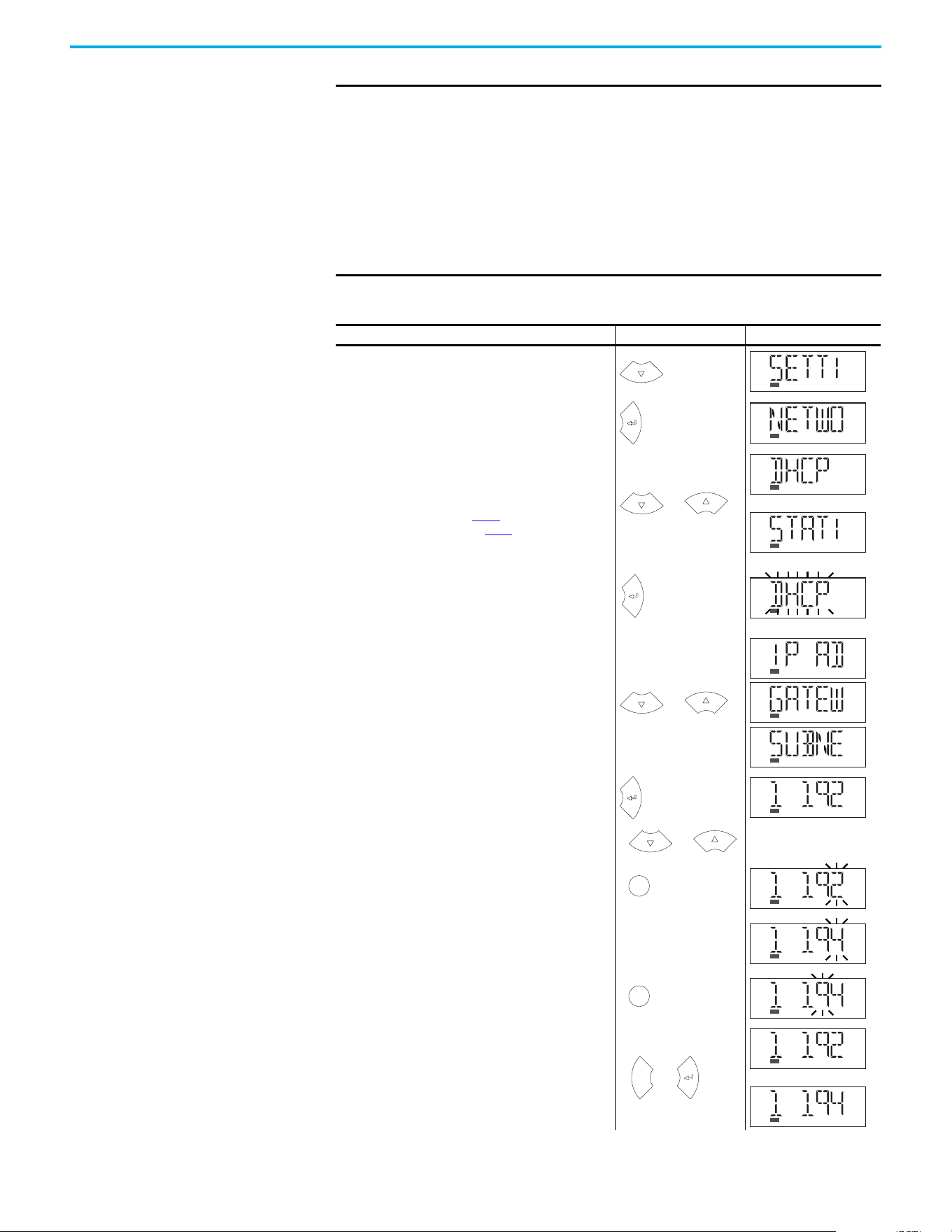
Rockwell Automation Publication 520-UM002E-EN-E - September 2024 47
Chapter 2 Start Up
IMPORTANT Regardless of the method used to set the adapter IP address, each node on
the EtherNet/IP network must have a unique IP address. To change an IP
address, you must set the new value and then power cycle the drive.
You can also use the Reset function, however all safety connections will
have to be disabled before this option is available.
You must enter a valid IP address configuration. With firmware 1.008 or
later, if an illegal IP address configuration exists upon power-up, for
example, if the IP address and gateway address are identical, the drive
faults and exhibits INIT FLT M22 - ILLEGAL ADDRESS on the display and the IP
address configuration changes to DHCP.
Configuring Network Settings
Step Keys Example Display
1. On the Device/Axis state screen, press the Down arrow to
go to the Settings menu.
2. Press Enter to display the Network Settings screen.
3. Press the Up or Down arrow to select either DHCP or Static
IP, then press Enter.
If you choose DHCP, go to step 4
.
If you choose Static IP, go to step 5.
4. Press Enter to confirm DHCP as the network configuration
option. Choosing DHCP automatically configures the IP
settings for your drive.
This completes the network configuration for your drive.
5. Choosing Static IP enables you to manually configure the
IP address, subnet mask, and gateway address for your
drive. Press the Up or Down arrow to scroll through the
settings.
6. In this example, we will start by configuring the IP
address. Select IP address, then press Enter to display
the first octet of the IP address.
7. Press the Up or Down arrow to scroll through the four
octets of the IP address.
8. Press Sel to edit an octet. The rightmost digit of the octet
will flash.
9. Press the Up or Down arrow to change the digit.
Press Sel to edit the digits on the left.
10.Press ESC to cancel a change and exit the edit mode.
Or
Press Enter to save a change and exit the edit mode.
or
or
or
or
Sel
Sel
Esc
or
or
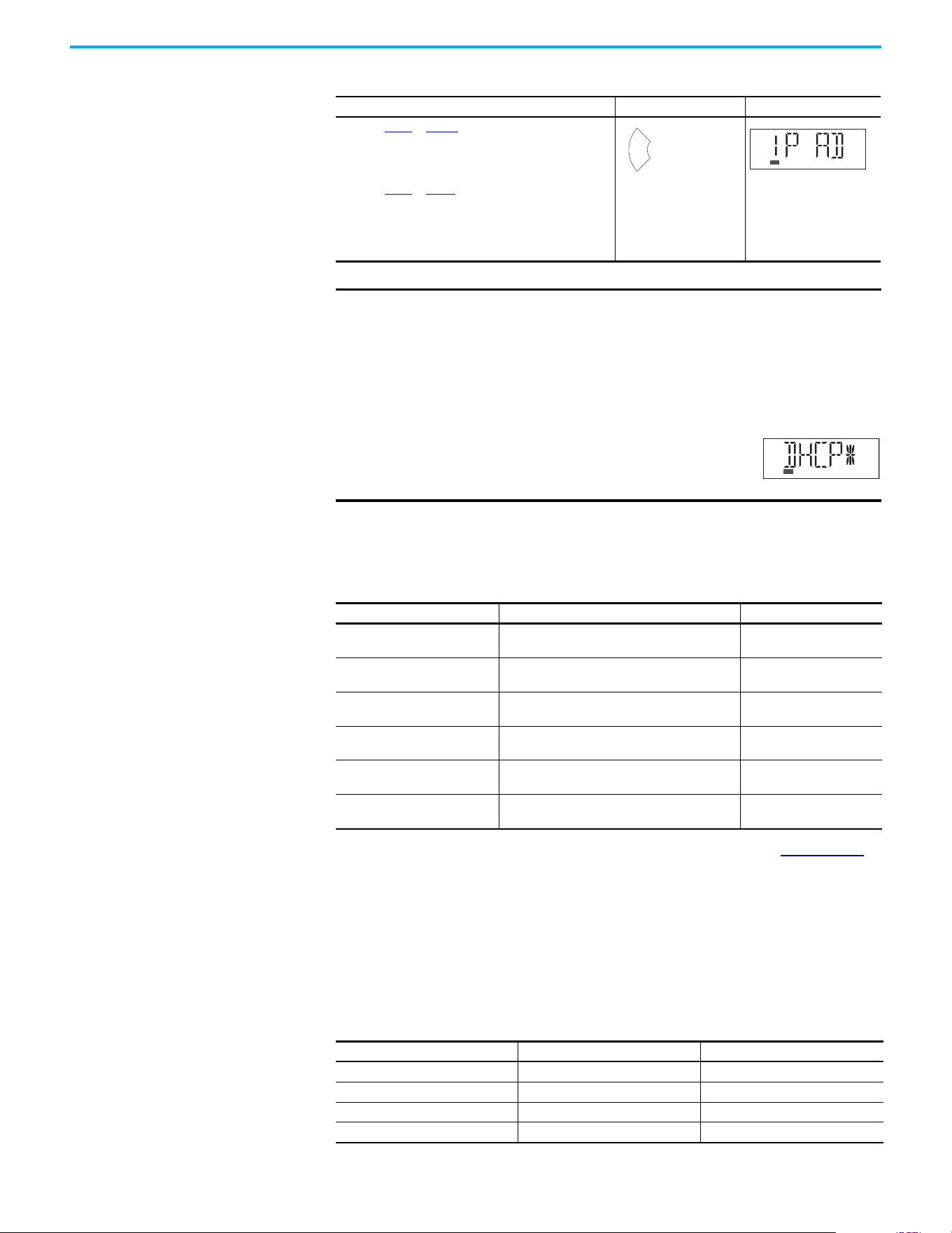
48 Rockwell Automation Publication 520-UM002E-EN-E - September 2024
Chapter 2 Start Up
Real-time Information Display
Once the drive is enabled and running and connected to a controller, the following information can
be accessed through the LCD screen.
See Integrated Motion on the EtherNet/IP Network Reference Manual, publication MOTION-RM003
,
for complete motion attribute description.
Drive Programming Tools Some features in the PowerFlex 527 drive are not supported by older configuration software tools.
It is strongly recommended that customers using such tools migrate to Studio 5000 Logix Designer
application (version 24 or later) with Add-on Profile (AOP) to enjoy a richer, full-featured
configuration experience.
Language Support
11.Repeat step 7 to step 10 to edit the values of the other
octets.
After you have finished configuring the IP address.
Press ESC to go back to the Static IP menu.
12.Repeat step 5 to step 11 to configure the subnet mask and
gateway address.
13.Power cycle the drive to store the new IP settings.
This completes the network configuration for your drive.
IMPORTANT You must cycle power to make network configuration changes persistent.
An asterisk (*) is shown next to the network configuration when viewing the
Device Info screen option to signify that a change has been made but has
not taken effect.
For example, after changing the network configuration from Static IP to
DHCP, when viewing the Device Info screen option, an asterisk (*) appears
next to the text “DHCP” on the LCD display.
The change takes effect and the asterisk is removed
after you cycle power to the drive.
Display configuration changes take effect immediately.
Real-time Information Description Example Display
Velocity Feedback
Displays the value of the velocity feedback in units/
sec. See motion attribute 454.
VELOCITY FDBK 0.0
Motor Current
Displays the value of the motor current in % motor
rated. See motion attribute 529.
MOTOR CURT 0.0
Motor Utilization
Displays the value of the motor utilization in %. See
motion attribute 635.
MOTOR UTIL 0.0
DC Bus Voltage
Displays the value of the DC Bus voltage in VDC. See
motion attribute 620.
DC BUS VLTG 0.0
Current Command
Displays the value of the torque current in % motor
rated. See motion attribute 524.
CURRENT CMD 0.0
Output Current
Displays the value of Output Current in Amps RMS.
See motion attribute 601.
OUTPUT CURT 0.0
Configuring Network Settings (Continued)
Step Keys Example Display
Esc
Languages Supported
Language Keypad/LCD Display Logix Designer Application
English Y Y
French Y Y
Spanish Y Y
Italian Y Y

Rockwell Automation Publication 520-UM002E-EN-E - September 2024 49
Chapter 2 Start Up
Using the Ethernet Port The PowerFlex 527 drive has dual embedded Ethernet ports that connect the drive to an
EtherNet/IP network. This enables communication with a Logix based control system for drive
control using CIP Motion commands. You can also upgrade the drive firmware or upload/download
a configuration easily using the Studio 5000 Logix Designer application.
The EtherNet/IP network offers a full suite of control, configuration, and data collection services by
layering the Common Industrial Protocol (CIP™) over the standard protocols used by the Internet
(TCP/IP and UDP). EtherNet/IP uses TCP/IP for general messaging/information exchange services
and UDP/IP for I/O messaging services for control applications.
Liner, Star, and Device Level Ring network topologies are supported by the PowerFlex 527 drive.
Plus, the application of the CIP Safety™ protocol enables the simultaneous transmission of safety
and standard control data and diagnostics information.
German Y Y
Japanese – Y
Portuguese Y Y
Simplified Chinese – Y
Korean – Y
Polish
(1)
Y–
Turkish
(1)
Y–
Czech
(1)
Y–
(1) Due to a limitation of the LCD display, some of the characters for Polish, Turkish, and Czech will be modified.
Languages Supported (Continued)
Language Keypad/LCD Display Logix Designer Application

50 Rockwell Automation Publication 520-UM002E-EN-E - September 2024
Chapter 2 Start Up
Notes:

Rockwell Automation Publication 520-UM002E-EN-E - September 2024 51
Chapter 3
Chapter
Chapter
Configuring the PowerFlex 527 Drive with
Integrated Motion
This chapter describes procedures on how to configure Integrated Motion on the EtherNet/IP
network control by using a PowerFlex 527 Drive.
Configure the Drive You can include the drive in your Studio 5000 Logix Designer application by adding it to a
configured EtherNet/IP module or controller and adding it under the I/O configuration tree. After
setting the network configuration, you can view the drive status information in the Studio 5000
environment and use it in your Studio 5000 Logix Designer application.
Set the Network Configuration
You can set the network configuration by using the LCD display and drive keypad.
1. When the LCD display is showing the Device/Axis state, use the keypad to navigate to
SETTINGS -> NETWORK. Then choose either STATIC IP or DHCP.
The default setting is STATIC IP.
2. If you chose STATIC IP, then you must configure the following settings:
-IP address
-Gateway
-Subnet mask
If you chose DHCP, the three settings above are configured automatically by the DHCP
server.
Settings are stored in nonvolatile memory. IP addressing can also be changed through the Module
Configuration dialog box in RSLinx® software. Changes to the IP addressing take effect after power
is cycled or reset. The drive is factory programmed to static IP address of 192.168.1.180.
See Configuring Network Settings on page 47
for help on configuring the IP settings.
Configure the Logix Designer
Application Project
These procedures assume that you have wired your PowerFlex 527 drive system. In this example,
the CompactLogix 5370 controller is used.
For help with using the Studio 5000 Logix Designer application (version 24 or later) application as it
applies to configuring the ControlLogix or CompactLogix controllers, see Additional Resources on
page 8.
Before you begin, make sure that you know the catalog number for each drive
component, the Logix module and/or controller used in your motion control
application.
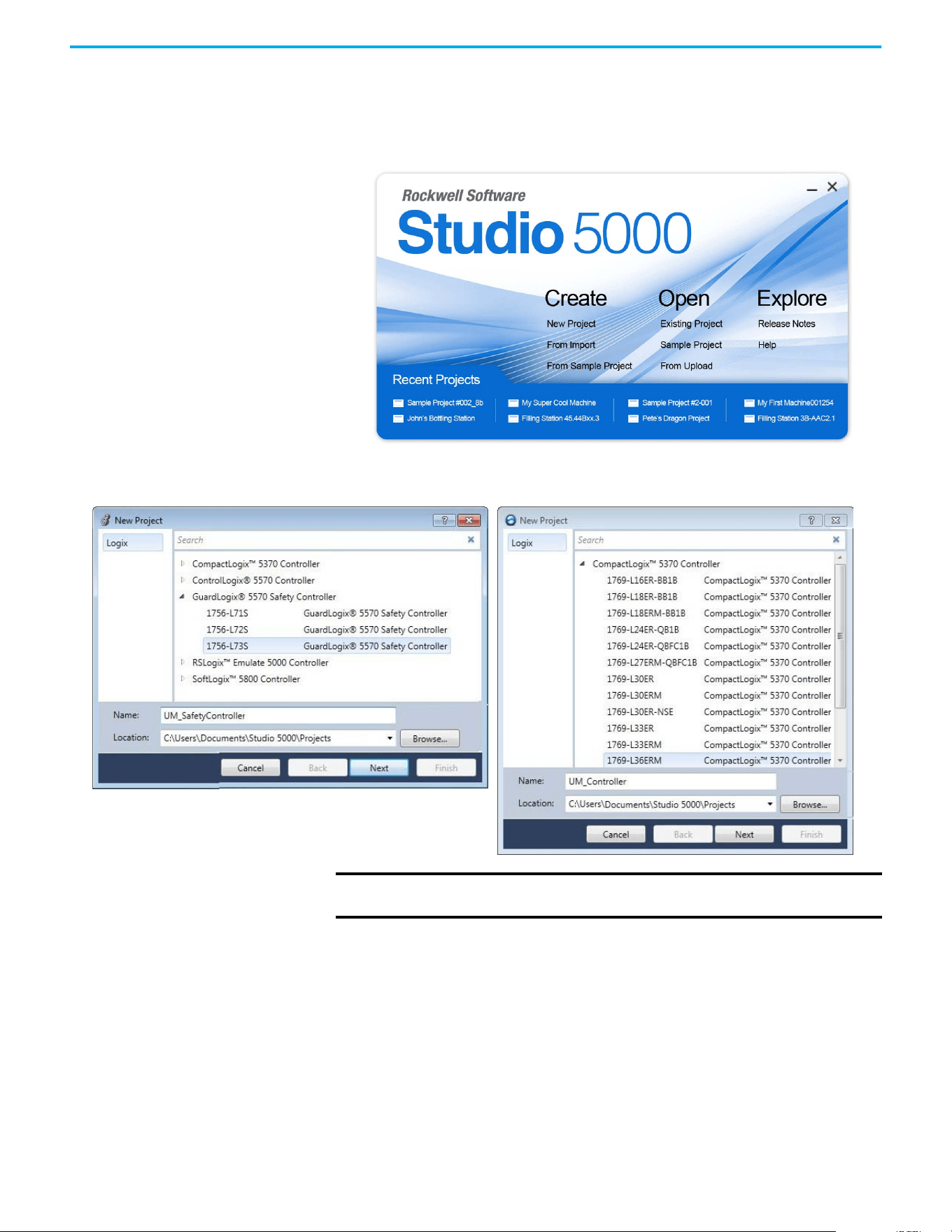
52 Rockwell Automation Publication 520-UM002E-EN-E - September 2024
Chapter 3 Configuring the PowerFlex 527 Drive with Integrated Motion
Configure the Logix 5000 Controller
Follow these steps to configure the controller.
1. Apply power to your controller and open your Logix Designer application.
2. From the Create menu, choose New Project.
The New Project dialog box appears.
If using a safety or non-safety ControlLogix controller, you must also use a 1756-EN2T, 1756-EN2TR,
or 1756-EN3TR EtherNet/IP module. If using a CompactLogix 5370 controller, it has dual embedded
EtherNet/IP ports.
In this example, the typical dialog boxes for 1756-L7xS GuardLogix 5570 safety controllers and
CompactLogix 5370 controllers are shown.
Follow these steps to configure your Logix 5000 controller.
1. Expand the Logix 5000 controller family and select your controller.
2. Type the file name.
3. Select Next.
IMPORTANT If you are configuring a PowerFlex 527 drive for integrated safety in a safety
application, you must use a GuardLogix safety controller.
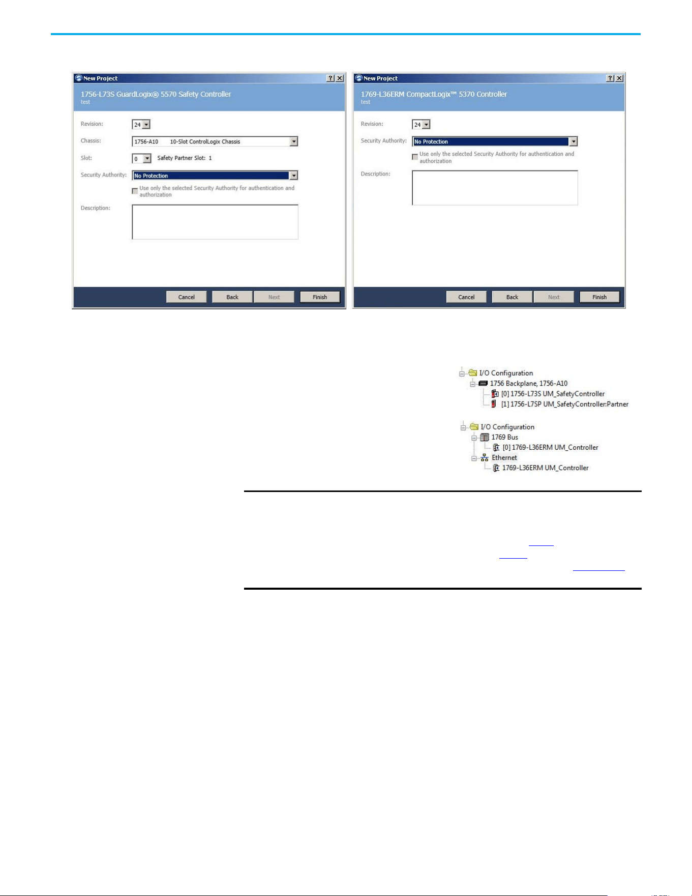
Rockwell Automation Publication 520-UM002E-EN-E - September 2024 53
Chapter 3 Configuring the PowerFlex 527 Drive with Integrated Motion
The New Project dialog box appears.
4. From the Revision pull-down menu, choose your software revision.
5. Select Finish.
The new controller appears in the Controller Organizer under the I/O Configuration folder.
6. Right-click I/O Configuration in the Controller Organizer and choose New Module.
IMPORTANT If your project includes a ControlLogix or GuardLogix controller, you need to
add an Ethernet communication module to your Bulletin 1756 chassis and
configure it for use in your application.
• For ControlLogix or GuardLogix controllers, go to step 6
.
• For CompactLogix 5370 controllers, go to step 13.
See the EtherNet/IP Network Devices User Manual, publication ENET-UM006
for more information.
Controller Organizer with
GuardLogix 1756-7xS controller
Controller Organizer with
CompactLogix 5370 controller
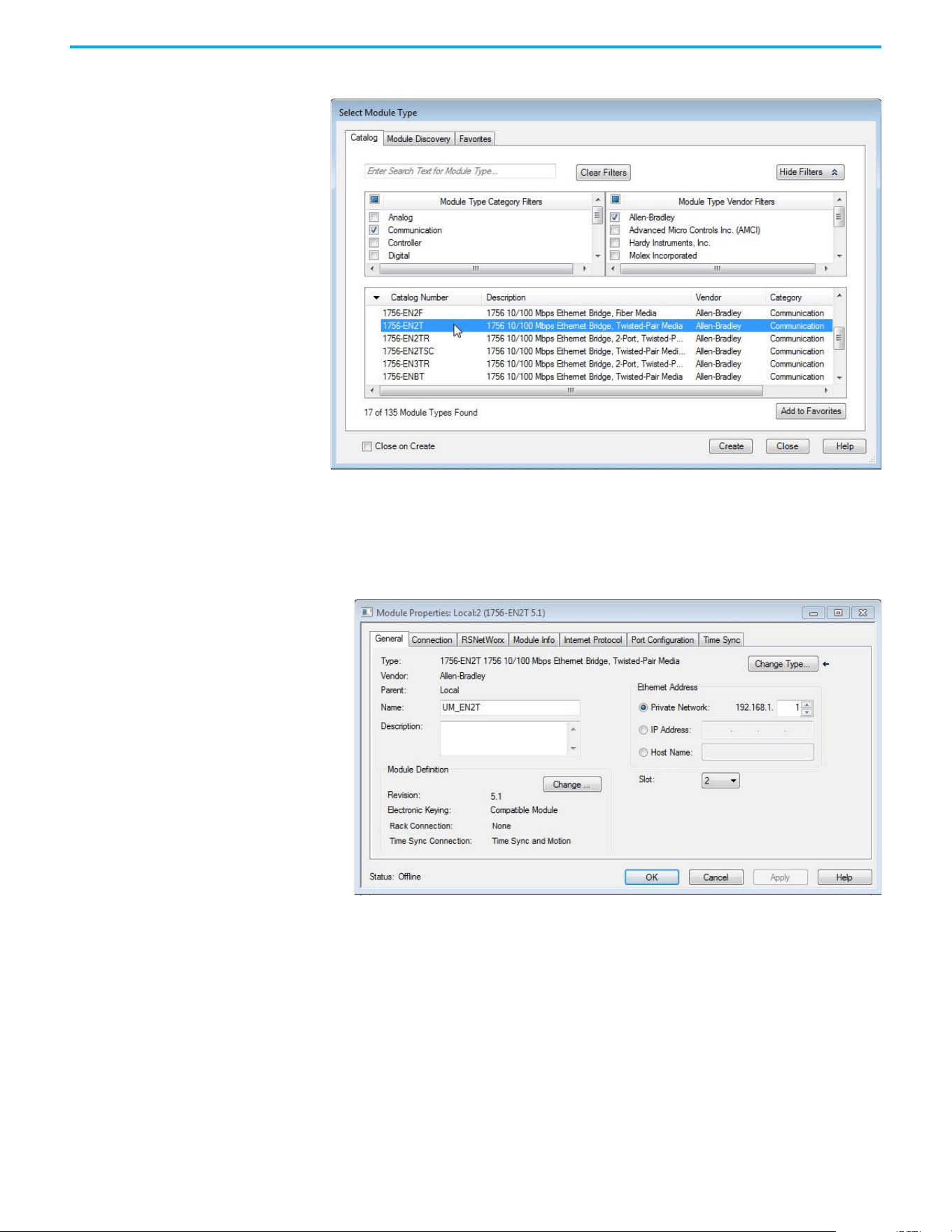
54 Rockwell Automation Publication 520-UM002E-EN-E - September 2024
Chapter 3 Configuring the PowerFlex 527 Drive with Integrated Motion
The Select Module Type dialog box appears.
7. By using the filters, select Communication and Allen-Bradley, and select 1756-EN2T, 1756-
EN2TR, or 1756-EN3TR as appropriate for your actual hardware configuration.
In this example, the 1756-EN2T module is selected.
8. Select Create.
The New Module dialog box appears.
a. Configure the new module.
b. Type the module Name.
c. Enter the Logix EtherNet/IP module slot (leftmost slot = 0).
d. Select an Ethernet Address option.
In this example, the Private Network address is selected.
e. Enter the address of your EtherNet/IP module.
In this example, the last octet of the address is 1.
f. Select Change in the Module Definition area.
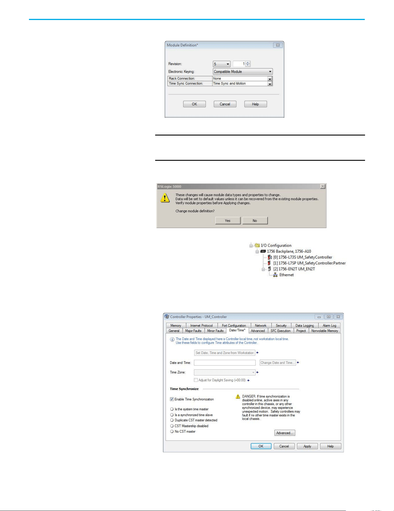
Rockwell Automation Publication 520-UM002E-EN-E - September 2024 55
Chapter 3 Configuring the PowerFlex 527 Drive with Integrated Motion
The Module Definition dialog box opens.
9. From the Time Sync Connection pull-down menu, choose Time Sync and Motion.
10. Select OK to close the Module Definition dialog box.
11. Select Yes when prompted to confirm your module definition changes.
12. Select OK to close the New Module dialog box.
13. From the Edit menu, choose Controller Properties.
The Controller Properties dialog box appears.
14. Select the Date/Time tab.
15. Check Enable Time Synchronization.
IMPORTANT Time Sync functionality is what enables motion control on an Ethernet
network. Without this setting, you won’t be able to run your motion
application.
Your new 1756-ENxT Ethernet module
appears under the I/O configuration
folder in the Controller Organizer.
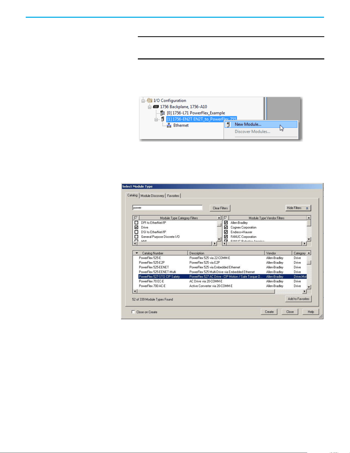
56 Rockwell Automation Publication 520-UM002E-EN-E - September 2024
Chapter 3 Configuring the PowerFlex 527 Drive with Integrated Motion
The motion modules set their clocks to the module you assign as the Grandmaster.
16. Select OK.
Add a PowerFlex 527 Drive Follow these instructions to add the PowerFlex 527 drive to your project.
1. Right-click the Ethernet network (node) and choose New Module…
2. Clear the small ‘select all’ check boxes, Module Type Category and Vendor Filters.
Alternatively, you can simply type “527” into the search box and choose the drive.
3. In the Module Type Category Filters window, select Drive.
In the Module Type Vendors Filters window, select Allen-Bradley.
IMPORTANT Check Enable Time Synchronization for all controllers that participate
in CIP Sync™. The overall CIP Sync network automatically promotes a
Grandmaster clock, unless the priority is set in the Advanced tab.
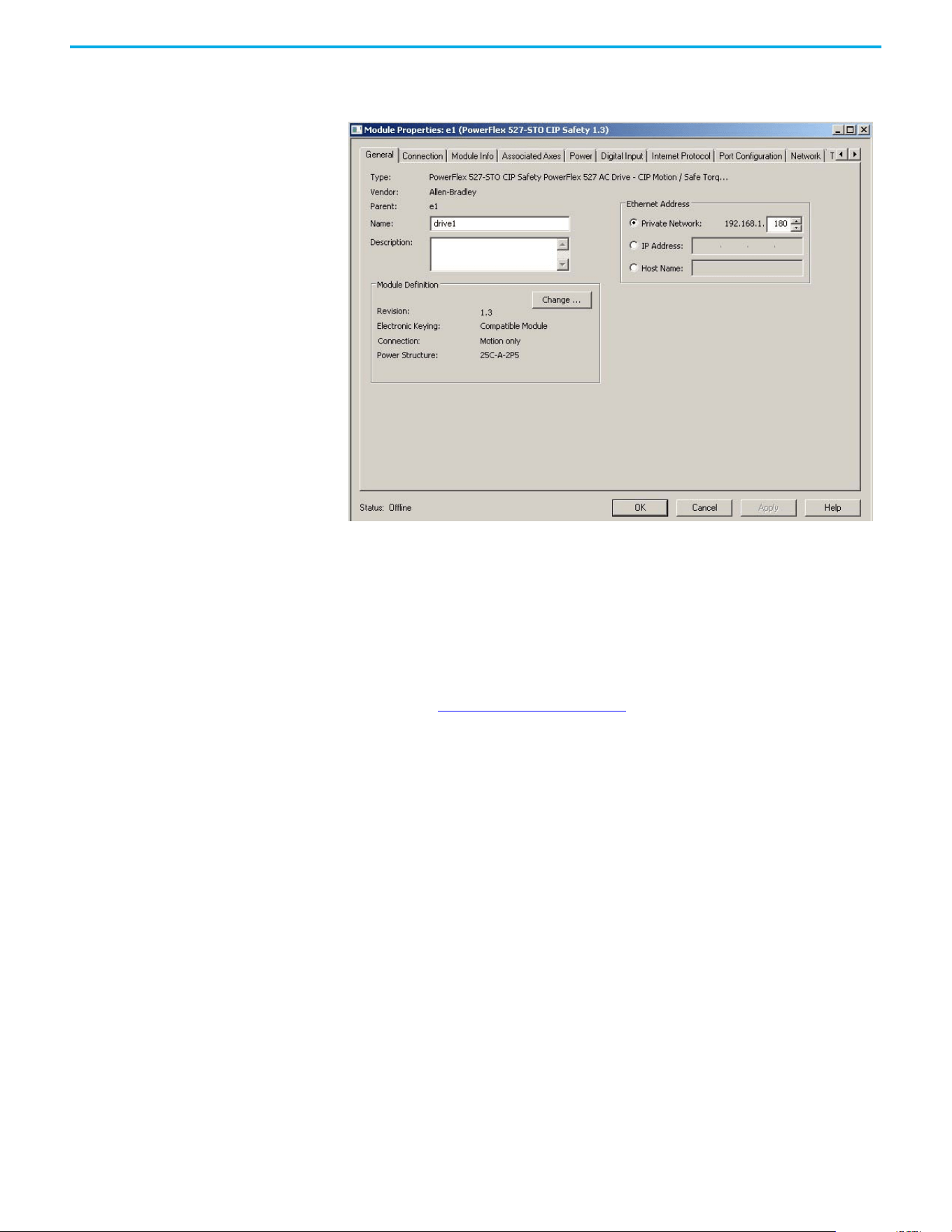
Rockwell Automation Publication 520-UM002E-EN-E - September 2024 57
Chapter 3 Configuring the PowerFlex 527 Drive with Integrated Motion
4. Choose the PowerFlex 527 drive and select Create.
The Module Properties dialog box appears.
5. Configure the new drive.
a. Type the drive Name.
b. Type a Description, if desired.
c. Select an Ethernet Address option.
In this example, the Private Network address is selected.
d. Enter the address of your PowerFlex 527 drive.
In this example, the last octet of the address is 180.
6. Proceed to Configure the PowerFlex 527 Drive
to continue configuring your drive.
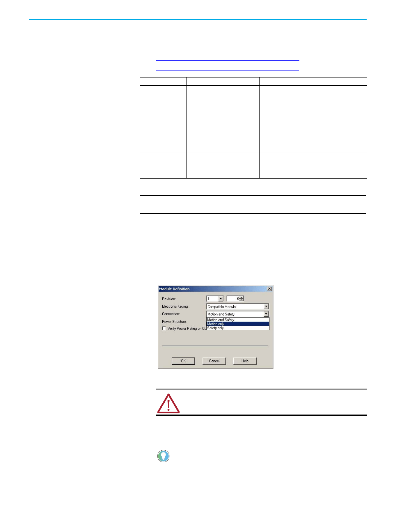
58 Rockwell Automation Publication 520-UM002E-EN-E - September 2024
Chapter 3 Configuring the PowerFlex 527 Drive with Integrated Motion
Configure the PowerFlex 527
Drive
After you have added a PowerFlex 527 drive to your project, you will need to configure the type of
safety connection suitable for your application. See the following sections for instructions on
configuring the drive for the different types of safety connections.
• Configure Drive with Hardwired Safety Connections on page 58
• Configure Drive with Integrated Safety Connections on page 59
Configure Drive with Hardwired Safety Connections
Follow these steps to configure the PowerFlex 527 drives with hardwired safety.
1. Verify that you have done the steps in Add a PowerFlex 527 Drive on page 56
before
proceeding.
2. Under Module Definition, select Change.
The Module Definition dialog box appears.
a. From the Electronic Keying pull-down menu, choose an option.
b. From the Connection pull-down menu, choose the Connection mode for your motion
application.
In this example, choose Motion only.
Connection Mode Controller Needed Description
Motion only
ControlLogix 5570,
GuardLogix 5570,
CompactLogix 5370,
ControlLogix 5580,
CompactLogix 5380, or
Compact GuardLogix 5370
(1)
(1) Catalog numbers containing the letter M.
• Hard-wired Safe Torque Off (STO) connections are
possible.
• This controller manages Motion.
• Another controller that has a Safety only connection
to the drive manages Safety.
Motion and Safety
GuardLogix 5570,
GuardLogix 5580,
Compact GuardLogix 5370
(1)
, or
Compact GuardLogix 5380
This controller manages Motion and Safety.
Safety only
GuardLogix 5570,
GuardLogix 5580,
Compact GuardLogix 5370, or
Compact GuardLogix 5380
• This controller manages Safety.
• Another controller that has a Motion only connection
to the drive manages Motion.
IMPORTANT To configure PowerFlex 527 drives, you must use the Logix Designer
application, version 24.00 or later.
WARNING: When using motion modules, the electronic keying must be
either “Exact Match” or “Compatible Keying”.
Never use “Disable Keying” with motion modules.
When ‘Safety’ appears in the Connection mode, integrated safety is
implied.
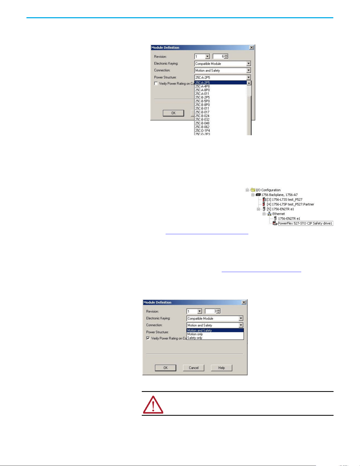
Rockwell Automation Publication 520-UM002E-EN-E - September 2024 59
Chapter 3 Configuring the PowerFlex 527 Drive with Integrated Motion
c. From the Power Structure pull-down menu, choose the catalog number that matches
your power structure.
d. Check the Verify Power Rating on Connection checkbox to confirm that the proper power
structure that is defined in the profile is the same as the connected drive. If the two do
not match, a connection error occurs, which indicates a power mismatch.
Verify Power Rating on Connection is checked by default. It is enabled in offline mode.
3. Select OK to close the Module Definition dialog box.
4. Select OK to close the Module Properties dialog box.
5. Proceed to Continue Drive Configuration on page 61
to continue configuring your drive.
Configure Drive with Integrated Safety Connections
Follow these steps to configure PowerFlex 527 drives with integrated safety.
1. Verify that you have done the steps in Add a PowerFlex 527 Drive on page 56
before
proceeding.
2. Under Module Definition, select Change.
The Module Definition dialog box appears.
a. From the Electronic Keying pull-down menu, choose an option.
b. From the Connection pull-down menu, choose the Connection mode for your motion
application.
Your PowerFlex 527 drive appears in the
Controller Organizer under the Ethernet
controller in the I/O configuration folder.
WARNING: When using motion modules, the electronic keying must be
either “Exact Match” or “Compatible Keying”.
Never use “Disable Keying” with motion modules.
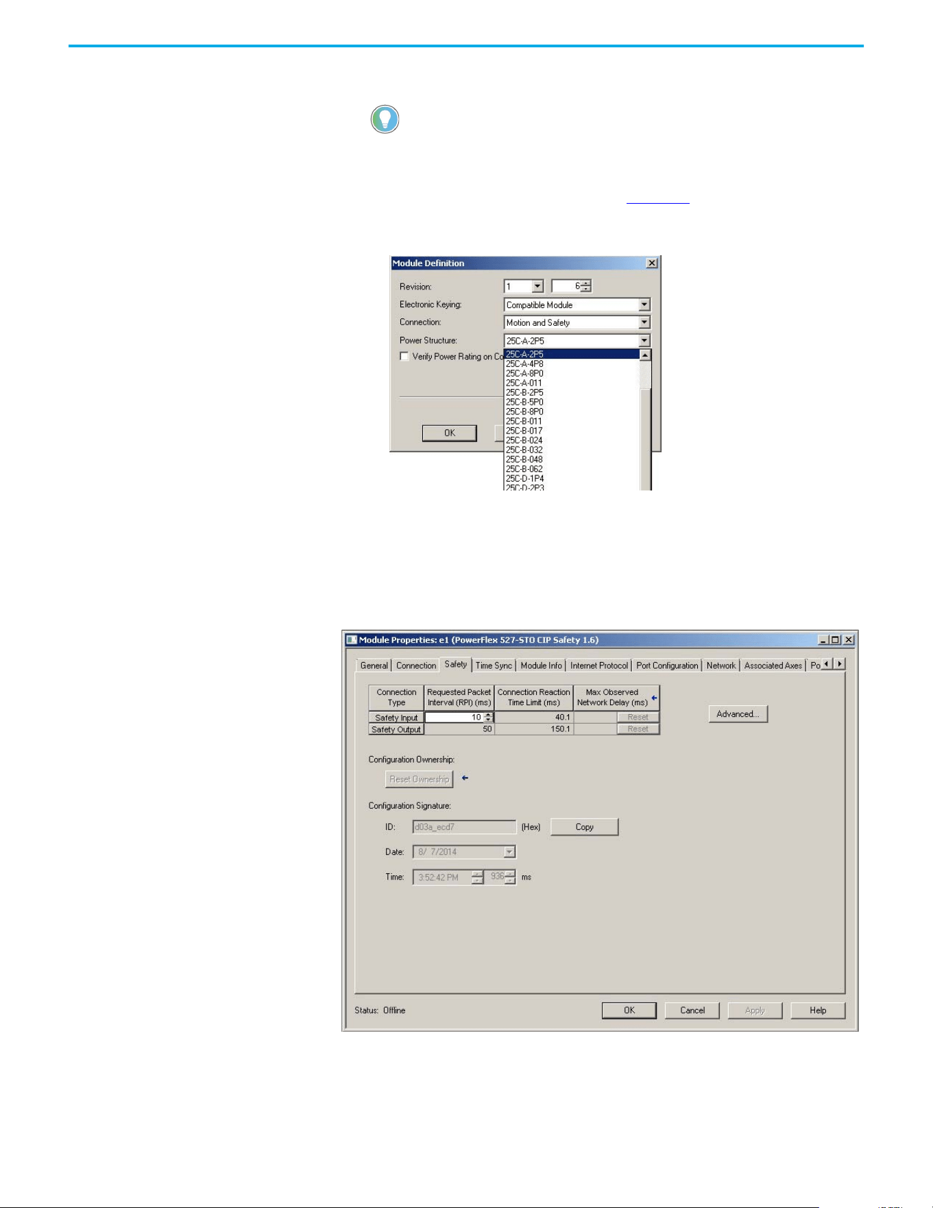
60 Rockwell Automation Publication 520-UM002E-EN-E - September 2024
Chapter 3 Configuring the PowerFlex 527 Drive with Integrated Motion
In this example, choose Motion and Safety.
The Safety Network Number (SNN) field populates automatically when the Connection mode
includes an integrated Motion and Safety or Safety-only connection. For a detailed
explanation of the safety network number, see the GuardLogix 5570 and Compact
GuardLogix 5370 Reference Manual, publication 1756-RM099
.
c. From the Power Structure pull-down menu, choose the catalog number that matches
your power structure.
d. Check the Verify Power Rating on Connection check box to confirm that the proper power
structure that is defined in the profile is the same as the connected drive. If the two do
not match, a connection error occurs, which indicates a power mismatch.
Verify Power Rating on Connection is checked by default. It is enabled in offline mode.
3. Select OK to close the Module Definition dialog box.
4. Select the Safety tab.
The connection between the controller and the PowerFlex 527 drive is based on the
following:
Drive catalog number must be 527 (integrated)
- Drive catalog number must be PowerFlex 527 (integrated)
- Drive Safety Network Number (SNN)
When ‘Safety’ appears in the Connection mode, integrated safety is
implied.
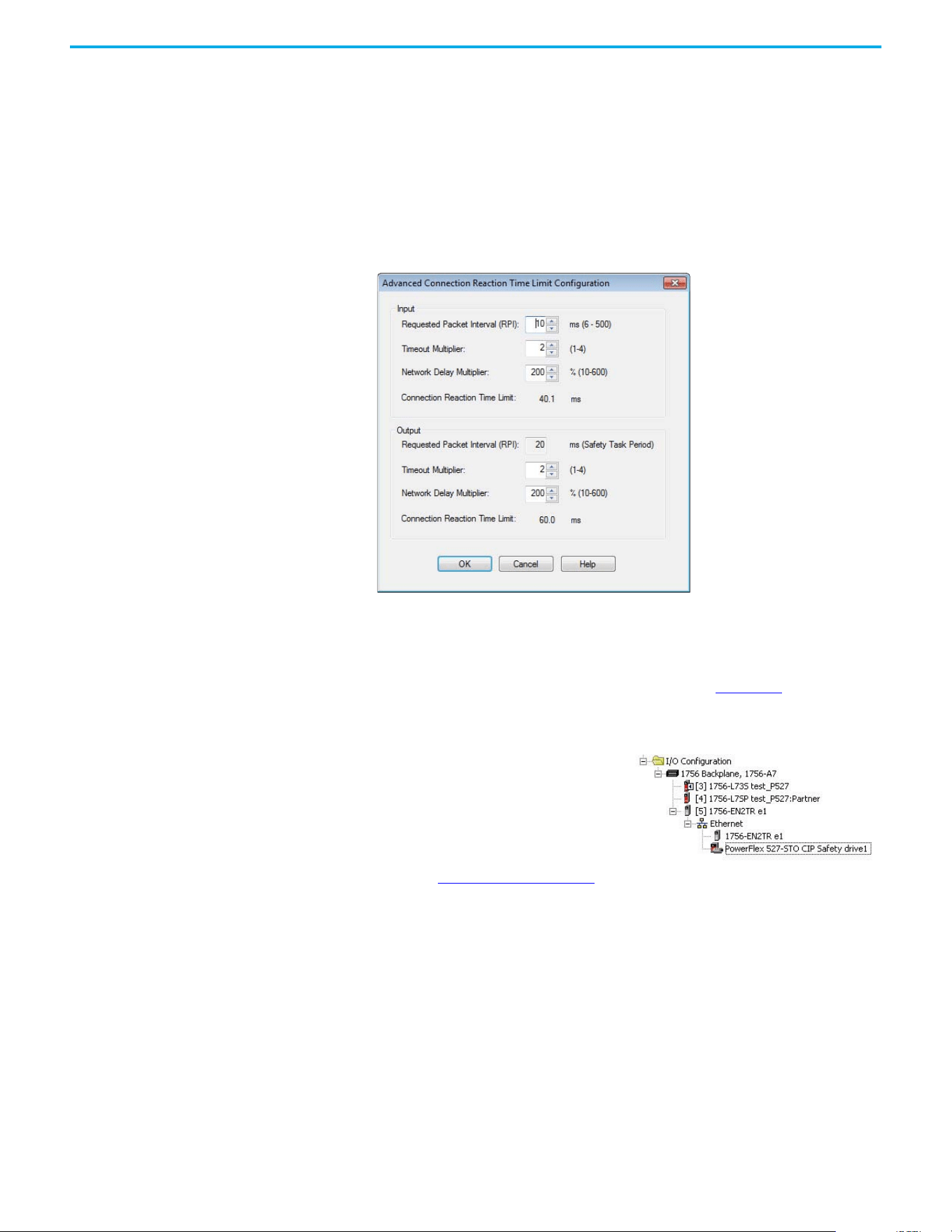
Rockwell Automation Publication 520-UM002E-EN-E - September 2024 61
Chapter 3 Configuring the PowerFlex 527 Drive with Integrated Motion
-GuardLogix slot number
- GuardLogix safety network number
- Path from the GuardLogix controller to the PowerFlex 527 drive
- Configuration signature
If any differences are detected, the connection between the GuardLogix controller and the
PowerFlex 527 drive is lost, and the yellow icon appears in the controller project tree after
you download the program.
5. Select Advanced.
The Advanced Connection Reaction Time Limit Configuration dialog box appears.
Analyze each safety channel to determine the appropriate settings. The smallest Input RPI
allowed is 6 ms. Selecting small RPI values consumes network bandwidth and can cause
nuisance trips because other devices cannot get access to the network.
For more information about the Advanced Connection Reaction Time Limit Configuration,
see the GuardLogix 5570 Controllers User Manual, publication 1756-UM022
.
6. Select OK to close the Advanced Connection Reaction Time Limit Configuration dialog box.
7. Select OK to close the Module Properties dialog box.
8. Proceed to Continue Drive Configuration
to continue configuring your drive.
Continue Drive Configuration
After you have established your PowerFlex 527 drive in the Logix Designer application, the
remaining configuration steps are the same regardless of the drive catalog number.
1. Right-click the PowerFlex 527 drive you created and choose Properties.
Your PowerFlex 527 drive appears in the
Controller Organizer under the Ethernet
controller in the I/O Configuration folder.
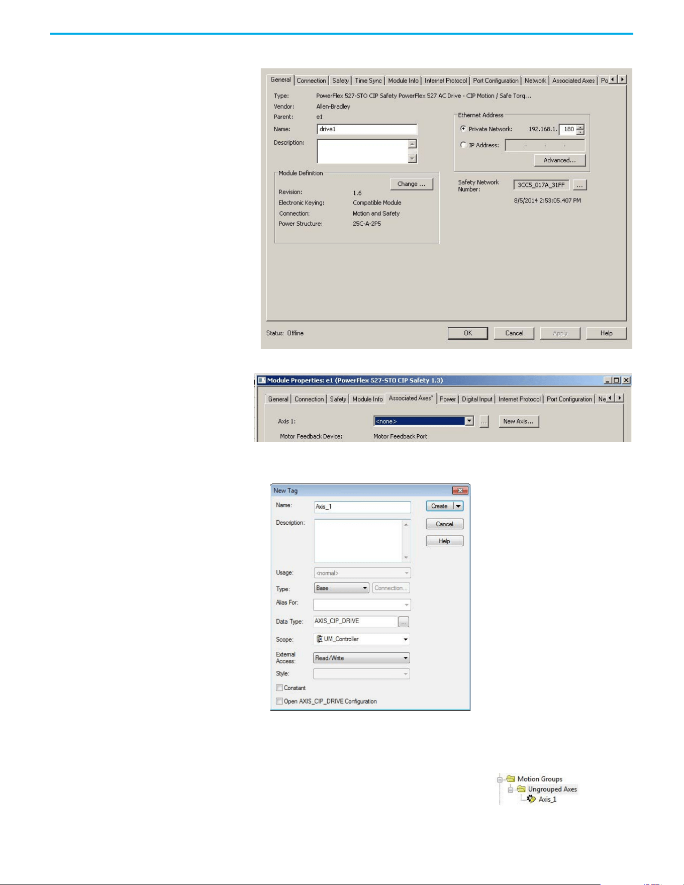
62 Rockwell Automation Publication 520-UM002E-EN-E - September 2024
Chapter 3 Configuring the PowerFlex 527 Drive with Integrated Motion
The Module Properties dialog box appears.
2. Select the Associated Axes tab.
3. Select New Axis.
The New Tag dialog box appears.
4. Type the axis Name.
AXIS_CIP_DRIVE is the default Data Type.
5. Select Create.
The axis (Axis_1 in this example) appears in the
Controller Organizer under Motion Groups >
Ungrouped Axes and is assigned as Axis 1.
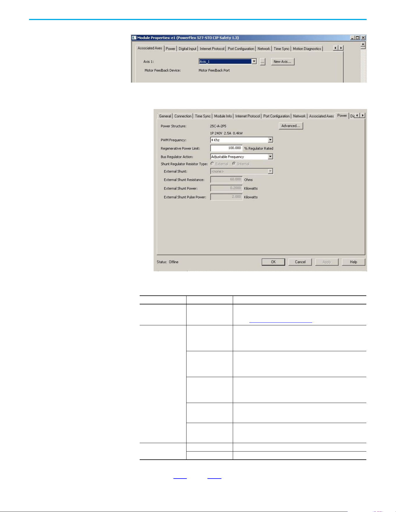
Rockwell Automation Publication 520-UM002E-EN-E - September 2024 63
Chapter 3 Configuring the PowerFlex 527 Drive with Integrated Motion
6. Select Apply.
7. Select the Power tab.
8. From the pull-down menu, choose the power options appropriate for your actual hardware
configuration.
9. Select OK.
10. Repeat step 1
through step 9 for each PowerFlex 527 drive.
Attribute Menu Description
PWM Frequency
•2 kHz
•4 kHz (Default)
•8 kHz
The value sets the carrier frequency for the Pulse Width Modulation
(PWM) output to the motor.
See the PWM Frequency Chart on page 64 for derating guidlines.
Bus Regulator Action
Disabled
This selection disables the internal DC bus voltage regulation feature
of the drive. Select this option if there is an external regenerative
brake or regenerative line supply that is connected to the drive DC
bus.
Shunt Regulator
This selection is used when either an external shunt resistor is
connected to the drive or the internal IGBT will be controlling the
power dissipation to the resistor (the type of shunt resistor is selected
below).
Adjustable Frequency
(Default)
This selection allows the drive to either change the torque limits or
ramp rate of the velocity to control the DC bus voltage. This option is
not recommended for positioning applications because it will override
the velocity and the system will overshoot or may not stop.
Shunt then Adjustable
Frequency
This selection allows the shunt resistor to absorb as much energy as it
is designed for, then transitions to adjustable frequency control if the
limit of the resistor has been reached.
Adjustable Frequency
then Shunt
This selection allows for adjustable frequency control of the DC bus. If
adjustable frequency control cannot maintain the DC bus within limits,
the shunt resistor will be activated.
Shunt Regulator
Resistor Type
Internal Not applicable for PowerFlex 527 drives.
External Enables the external shunt (internal shunt option is disabled).
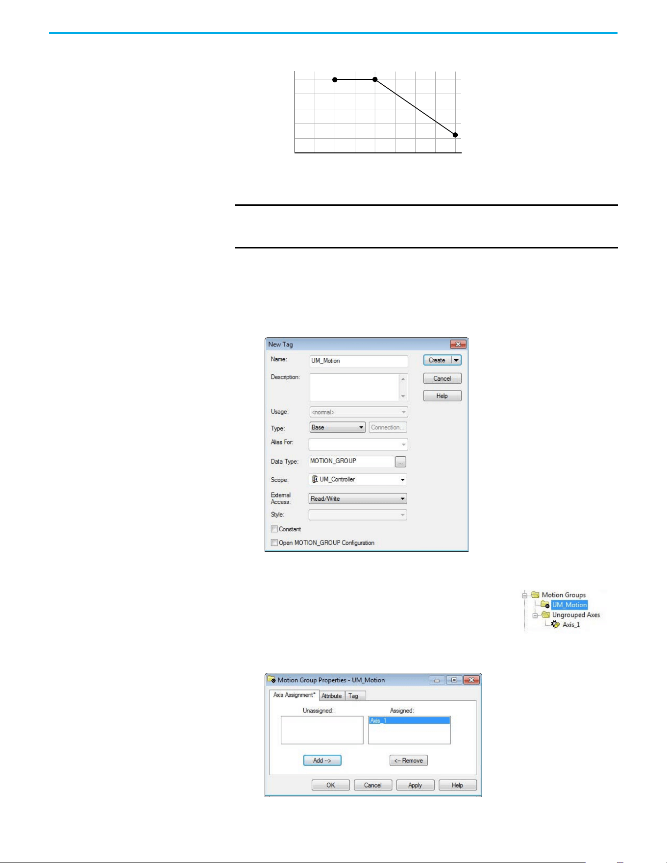
64 Rockwell Automation Publication 520-UM002E-EN-E - September 2024
Chapter 3 Configuring the PowerFlex 527 Drive with Integrated Motion
PWM Frequency Chart
Configure the Motion Group
Follow these steps to configure the motion group.
1. In the Controller Organizer, right-click Motion Groups and choose New Motion Group.
The New Tag dialog box appears.
2. Type the new motion group Name.
3. Select Create.
.
4. Right-click the new motion group and choose Properties.
The Motion Group Properties dialog box appears.
IMPORTANT Ignoring derating guidelines can cause reduced drive performance. The
drive may automatically reduce the PWM carrier frequency at low output
speeds, unless prevented from doing so.
84
88
80
96
100
92
8
7
6
54321
% Output Current (A)
Carrier Frequency (kHz)
Your new motion group appears in the Controller Organizer under
the Motion Groups folder.
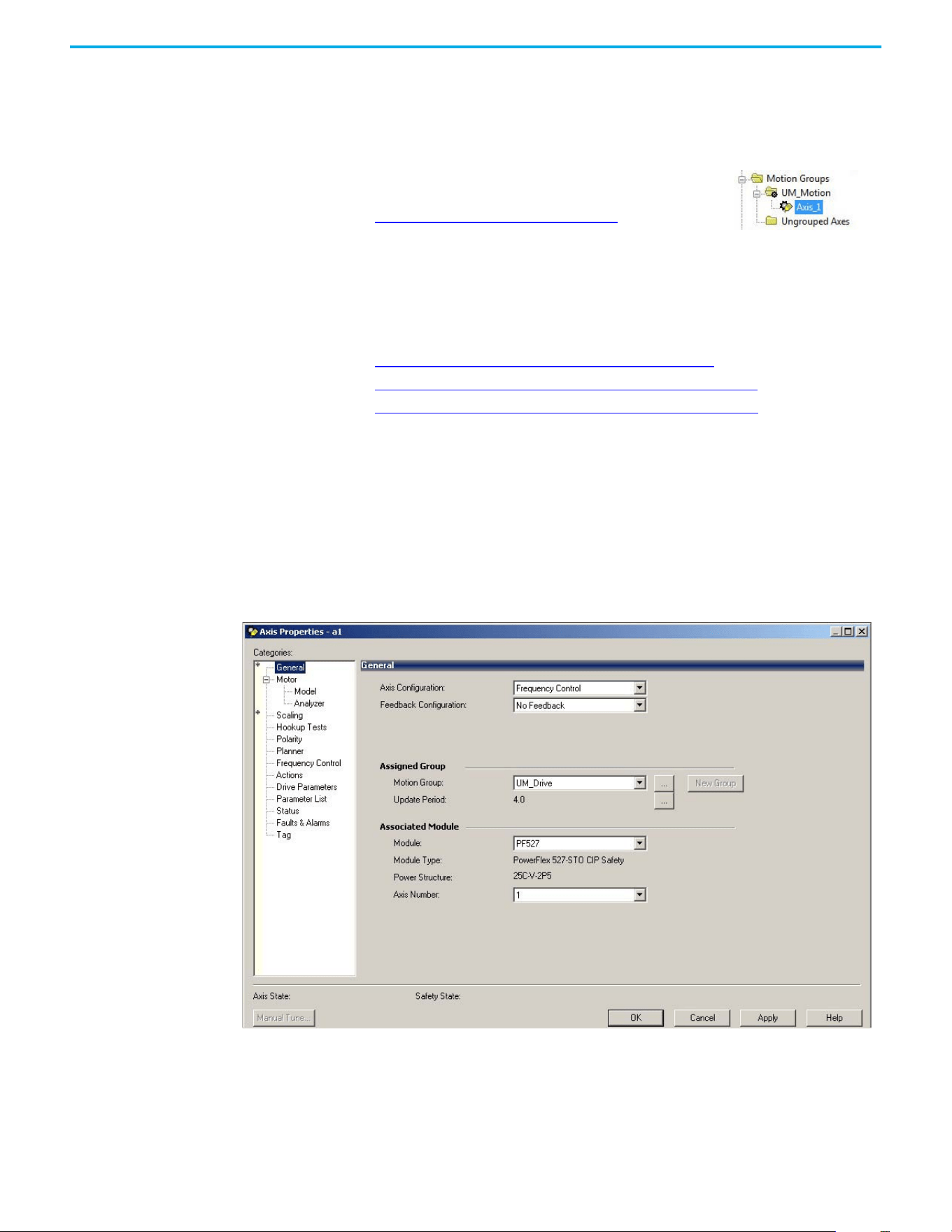
Rockwell Automation Publication 520-UM002E-EN-E - September 2024 65
Chapter 3 Configuring the PowerFlex 527 Drive with Integrated Motion
5. Select the Axis Assignment tab and move your axes (created earlier) from Unassigned to
Assigned.
6. Select the Attribute tab and edit the default values as appropriate for your application.
7. Select OK.
.
Configure Axis Properties
Axis configuration depends on the motor or other devices (for example, an external encoder)
associated with each axis. This section provides guidelines for configuring induction motors.
• Configure Induction Motor Axis Properties (Frequency Control)
• Configure Induction Motors Axis Properties (Velocity Loop) on page 68
• Configure Induction Motors Axis Properties (Position Loop) on page 72
Configure Induction Motor Axis Properties (Frequency Control)
The PowerFlex 527 drives support basic Volts/Hertz (V/Hz), Fan/Pump Volts/Hertz, Sensorless
Vector Control (SVC), and Sensorless Vector Control (SVC) Economy frequency control methods.
Follow these steps to configure the induction motor axis properties.
1. In the Controller Organizer, right-click an axis and choose Properties.
2. Select the General category.
The General and Associated Module dialog box appears.
3. From the Axis Configuration pull-down menu, choose Frequency Control.
4. From the Module pull-down menu, choose your PowerFlex 527 drive.
The Module Type and Power Structure fields populate with the chosen drive catalog
number.
5. Select Apply.
Your axis moves to the new motion group.
To get the minimum motion group base update rate, see
Motion Group Base Update Rate on page 155
.
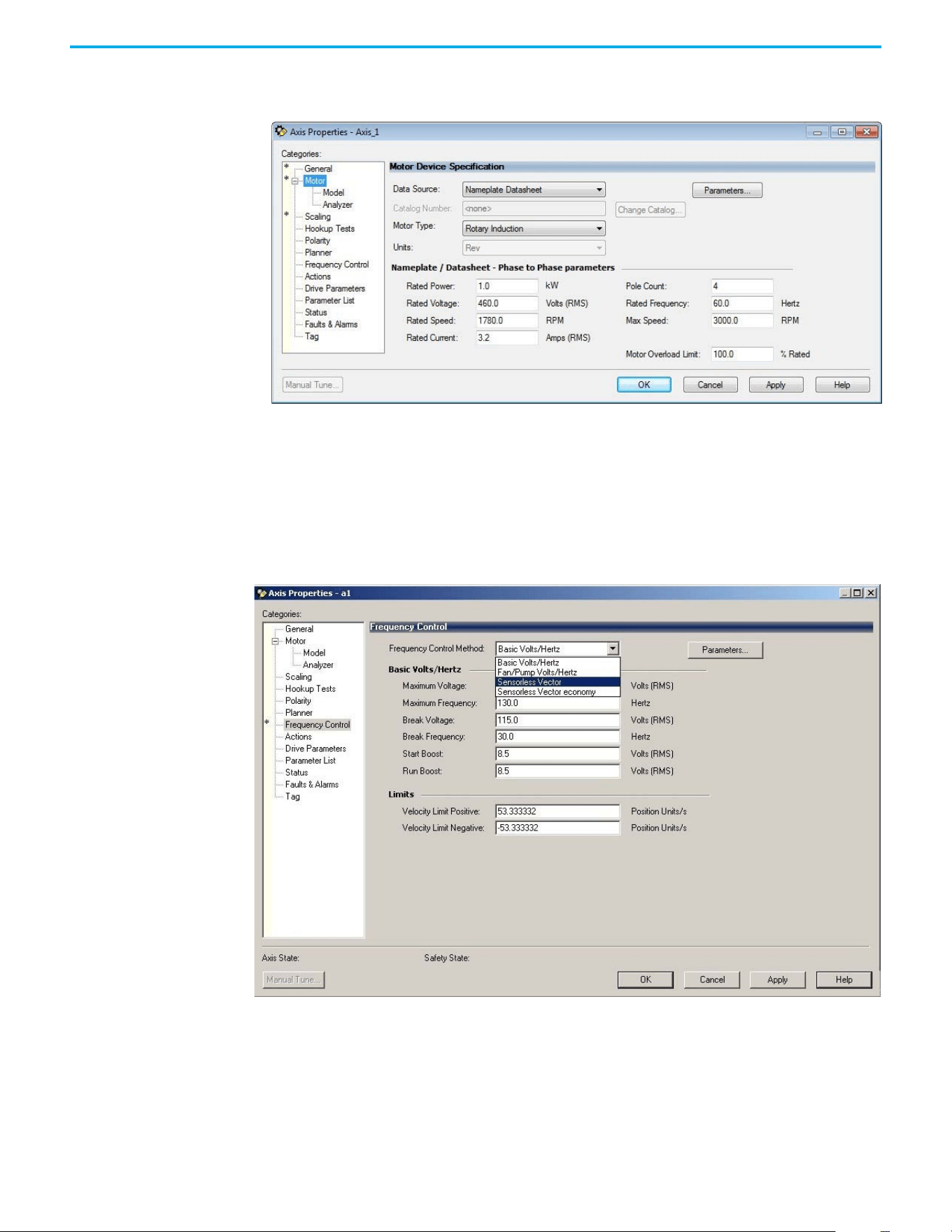
66 Rockwell Automation Publication 520-UM002E-EN-E - September 2024
Chapter 3 Configuring the PowerFlex 527 Drive with Integrated Motion
6. Select the Motor category.
The Motor Device Specification dialog box appears.
7. From the Data Source pull-down menu, choose Nameplate Datasheet.
This is the default setting.
8. From the Motor Type pull-down menu, choose Rotary Induction.
9. From the motor Nameplate / Datasheet, enter the Phase to Phase values.
10. Select Apply.
11. Select the Frequency Control category.
The Frequency Control dialog box appears.
12. From the Frequency Control Method pull-down menu, choose the method appropriate for
your application.
13. If you chose the Basic Volts/Hertz method, enter the nameplate data for your motor in the
Basic Volts/Hertz fields.
If you chose the Sensorless Vector method, the Basic Volts/Hertz fields are dimmed.
14. Select Apply.
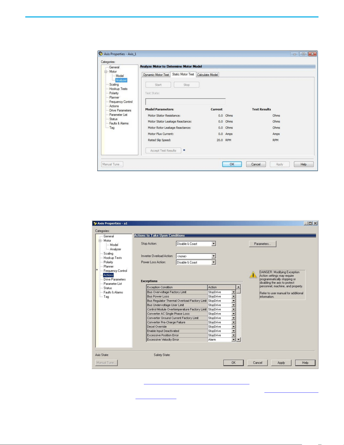
Rockwell Automation Publication 520-UM002E-EN-E - September 2024 67
Chapter 3 Configuring the PowerFlex 527 Drive with Integrated Motion
15. If you chose the Sensorless Vector or Sensorless Vector Economy method, select the Motor >
Analyzer category.
The Analyze Motor to Determine Motor Model dialog box appears.
16. Select the Static Motor Test tab.
17. Select Start to run the test and measure Motor Stator Resistance.
If you chose the Basic Volts/Hertz category, you can skip this test.
18. Select the Actions category.
The Actions to Take Upon Conditions dialog box appears.
From this dialog box, you can program actions and change the action for exceptions (faults).
See Logix 5000 Controller and Drive Behavior on page 119
for more information.
Some out-of-box (OOB) settings will need to be applied here. See Recommended Out-of-Box
Settings on page 153 for more information.
19. Select the Parameter List category.
The Motion Axis Parameters dialog box appears.
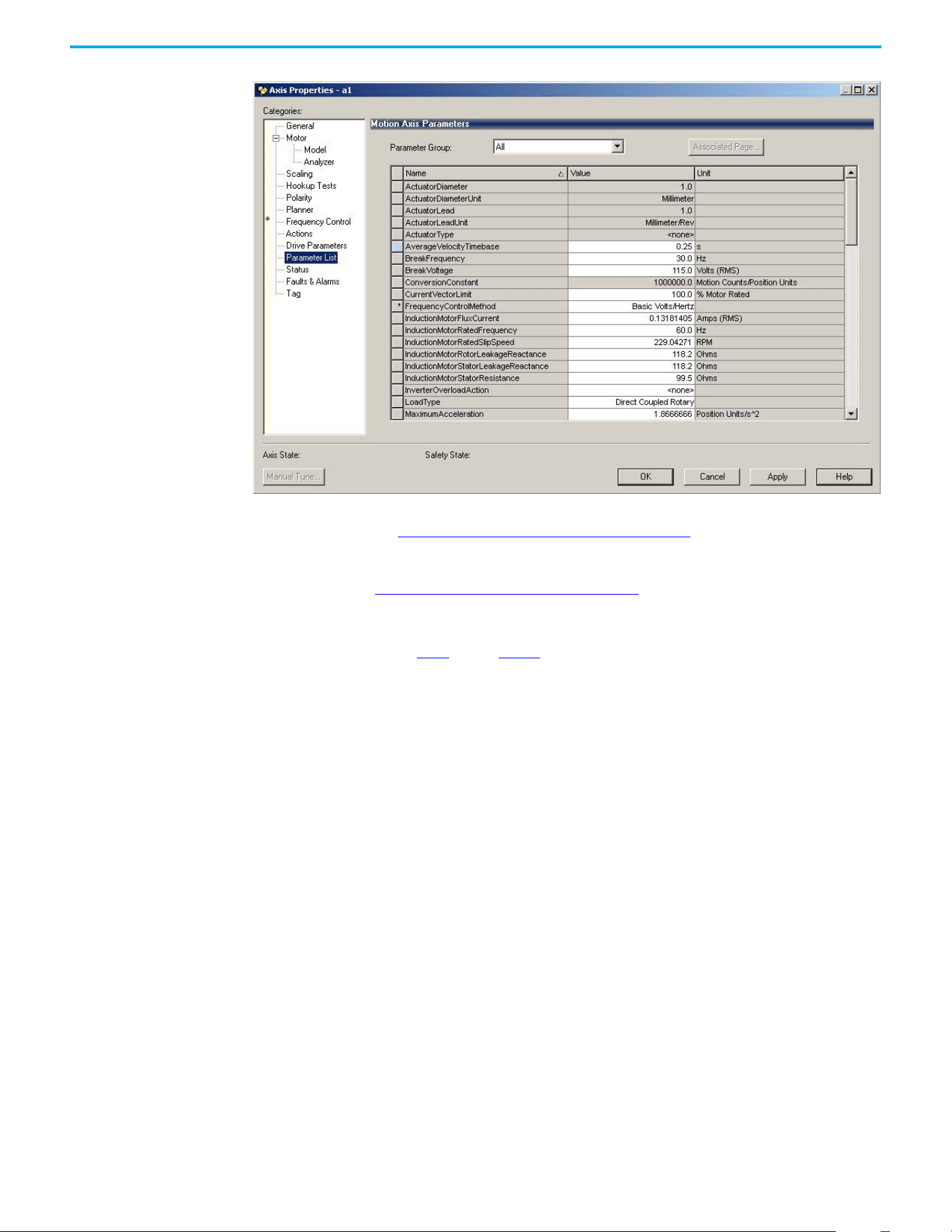
68 Rockwell Automation Publication 520-UM002E-EN-E - September 2024
Chapter 3 Configuring the PowerFlex 527 Drive with Integrated Motion
From this dialog box, you can program actions and change the action for exceptions (faults).
See Logix 5000 Controller and Drive Behavior on page 119
for more information.
To obtain the best performance from the drive regardless of which control method you are
using, you should configure the recommended out-of-box settings as described in
Recommended Out-of-Box Settings on page 153
first before configuring further for your
application.
20. Select OK.
21. Repeat step 1
through step 20 for each induction motor axis.
Configure Induction Motors Axis Properties (Velocity Loop)
Follow these steps to configure the induction motor axis properties.
1. In the Controller Organizer, right-click an axis and choose Properties.
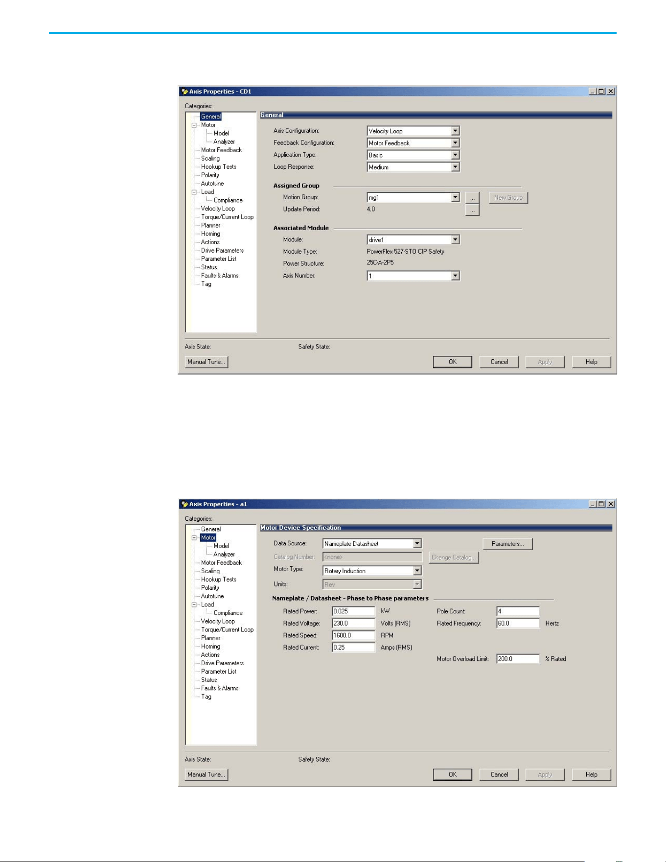
Rockwell Automation Publication 520-UM002E-EN-E - September 2024 69
Chapter 3 Configuring the PowerFlex 527 Drive with Integrated Motion
2. Select the General category.
The General and Associated Module dialog box appears.
3. From the Axis Configuration pull-down menu, choose Velocity Loop.
4. From the Module pull-down menu, choose your PowerFlex 527 drive.
The Module Type and Power Structure fields populate with the chosen drive catalog
number.
5. Select Apply.
6. Select the Motor category.
The Motor Device Specification dialog box appears.
7. From the Data Source pull-down menu, choose Nameplate Datasheet.
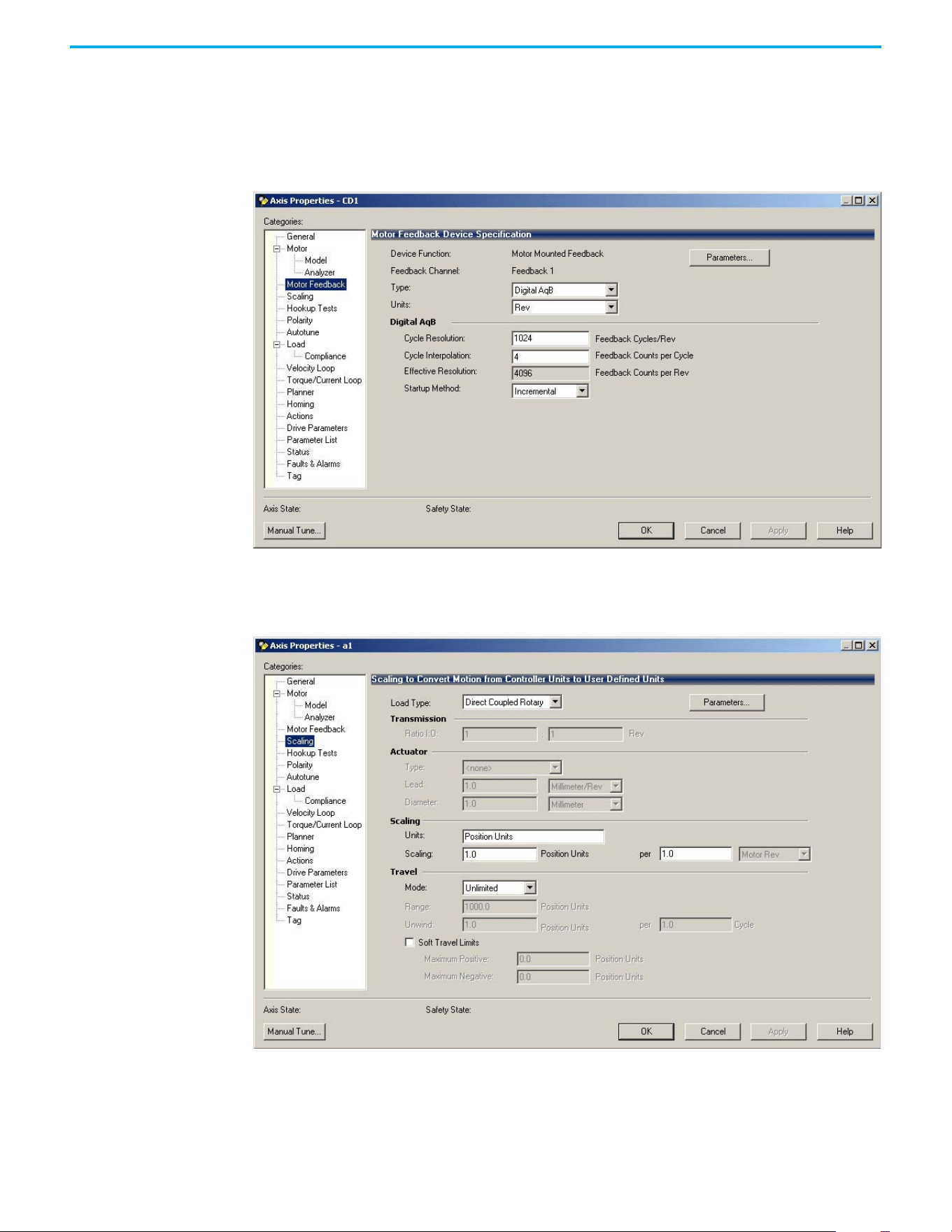
70 Rockwell Automation Publication 520-UM002E-EN-E - September 2024
Chapter 3 Configuring the PowerFlex 527 Drive with Integrated Motion
This is the default setting.
8. From the Motor Type pull-down menu, choose Rotary Induction.
9. From the motor Nameplate / Datasheet, enter the Phase to Phase values.
10. Select Apply.
11. Select the Motor Feedback category.
12. Enter the specifications of your encoder into the fields.
13. Select Apply.
14. Select the Scaling category and edit the values as appropriate for your application.
15. Select Apply if you make changes.
16. Select the Actions category.
The Actions to Take Upon Conditions dialog box appears.
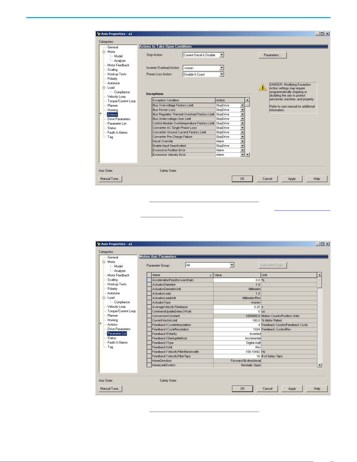
Rockwell Automation Publication 520-UM002E-EN-E - September 2024 71
Chapter 3 Configuring the PowerFlex 527 Drive with Integrated Motion
From this dialog box, you can program actions and change the action for exceptions (faults).
See Logix 5000 Controller and Drive Behavior on page 119
for more information.
Some out-of-box (OOB) settings will need to be applied here. See Recommended Out-of-Box
Settings on page 153 for more information.
17. Select the Parameter List category.
The Motion Axis Parameters dialog box appears.
From this dialog box, you can program actions and change the action for exceptions (faults).
See Logix 5000 Controller and Drive Behavior on page 119
for more information.
To obtain the best performance from the drive regardless of which control method you are
using, you should configure the recommended out-of-box settings as described in
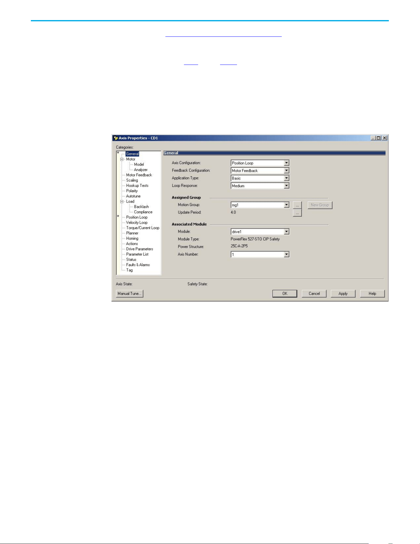
72 Rockwell Automation Publication 520-UM002E-EN-E - September 2024
Chapter 3 Configuring the PowerFlex 527 Drive with Integrated Motion
Recommended Out-of-Box Settings on page 153 first before configuring further for your
application.
18. Select OK.
19. Repeat step 1
through step 18 for each induction motor axis.
Configure Induction Motors Axis Properties (Position Loop)
Follow these steps to configure the induction motor axis properties.
1. In the Controller Organizer, right-click an axis and choose Properties.
2. Select the General category.
The General and Associated Module dialog box appears.
3. From the Axis Configuration pull-down menu, choose Position Loop.
4. From the Module pull-down menu, choose your PowerFlex 527 drive.
The Module Type and Power Structure fields populate with the chosen drive catalog
number.
5. Select Apply.
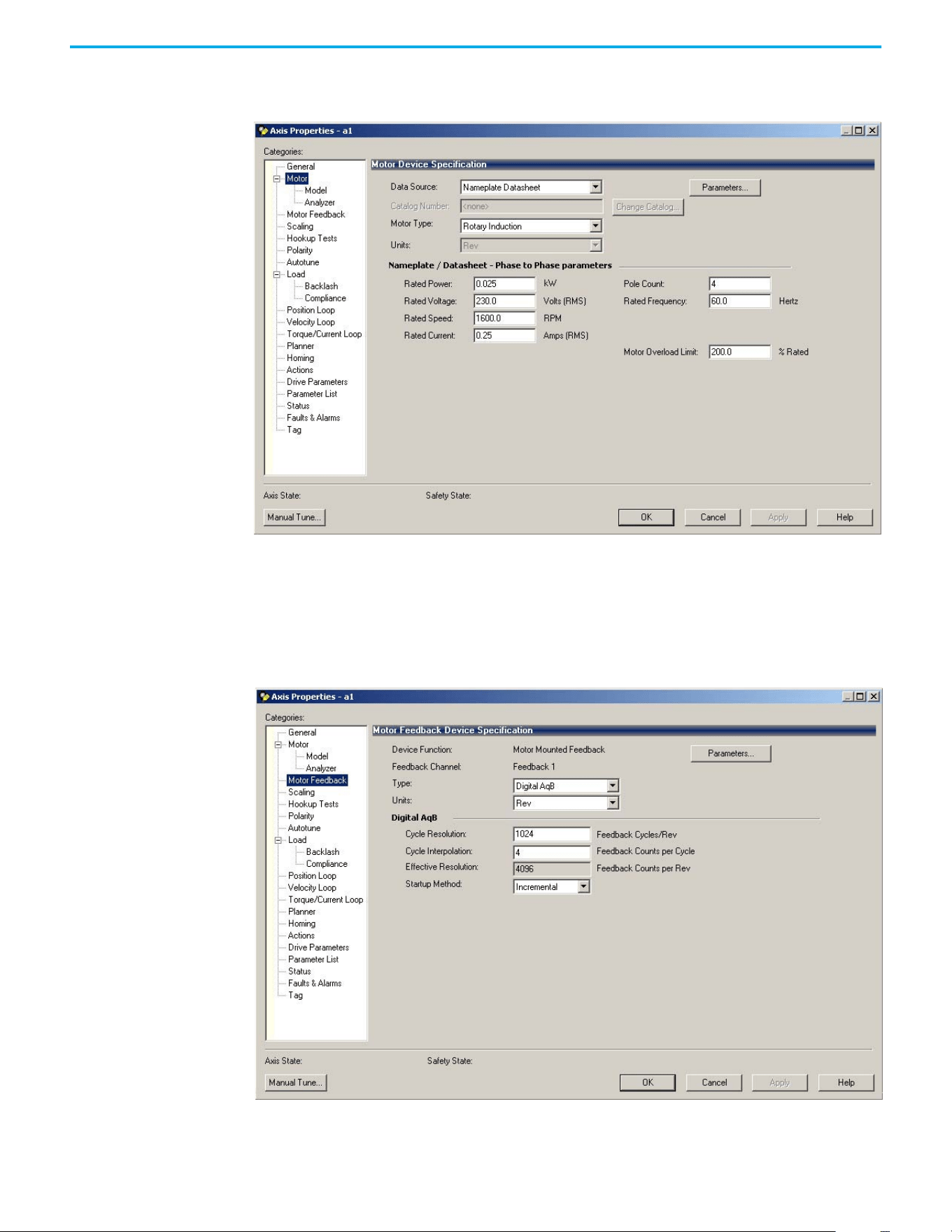
Rockwell Automation Publication 520-UM002E-EN-E - September 2024 73
Chapter 3 Configuring the PowerFlex 527 Drive with Integrated Motion
6. Select the Motor category.
The Motor Device Specification dialog box appears.
7. From the Data Source pull-down menu, choose Nameplate Datasheet.
This is the default setting.
8. From the Motor Type pull-down menu, choose Rotary Induction.
9. From the motor Nameplate / Datasheet, enter the Phase to Phase values.
10. Select Apply.
11. Select the Motor Feedback category.
12. Enter the specifications of your encoder into the fields.
13. Select Apply.
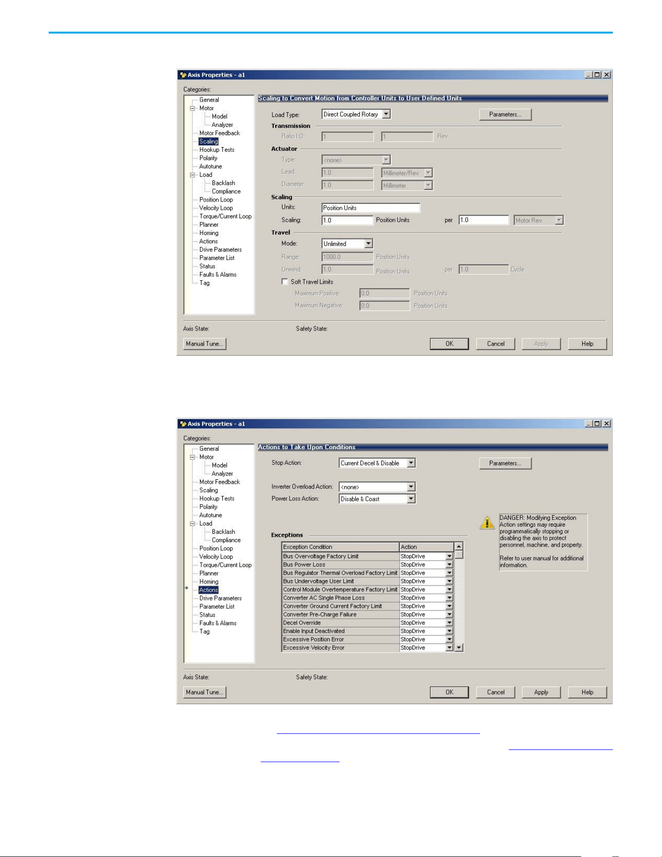
74 Rockwell Automation Publication 520-UM002E-EN-E - September 2024
Chapter 3 Configuring the PowerFlex 527 Drive with Integrated Motion
14. Select the Scaling category and edit the values as appropriate for your application.
15. Select Apply if you make changes.
16. Select the Actions category.
The Actions to Take Upon Conditions dialog box appears.
From this dialog box, you can program actions and change the action for exceptions (faults).
See Logix 5000 Controller and Drive Behavior on page 119
for more information.
Some out-of-box (OOB) settings will need to be applied here. See Recommended Out-of-Box
Settings on page 153 for more information.
17. Select the Parameter List category.
The Motion Axis Parameters dialog box appears.
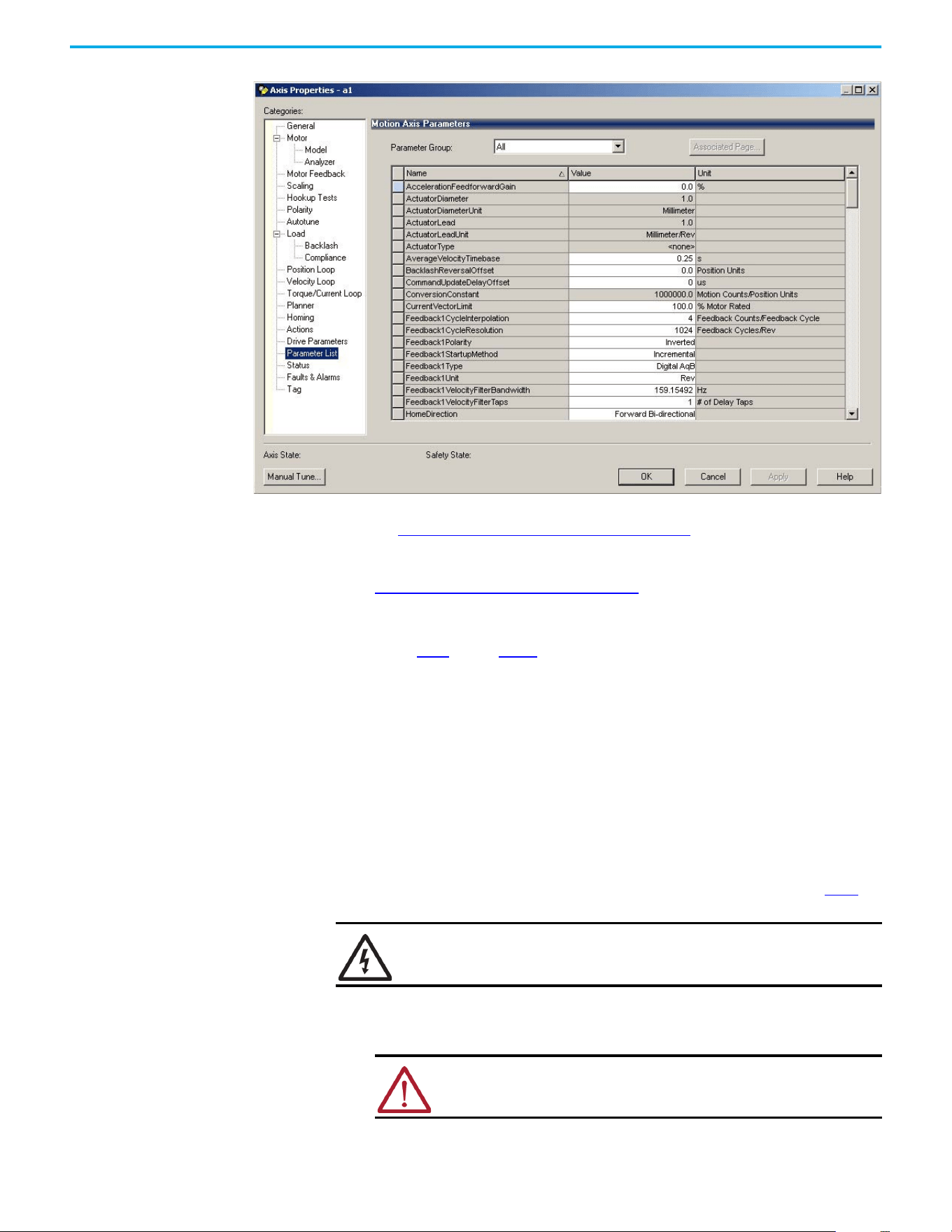
Rockwell Automation Publication 520-UM002E-EN-E - September 2024 75
Chapter 3 Configuring the PowerFlex 527 Drive with Integrated Motion
From this dialog box, you can program actions and change the action for exceptions (faults).
See Logix 5000 Controller and Drive Behavior on page 119 for more information.
To obtain the best performance from the drive regardless of which control method you are
using, you should configure the recommended out-of-box settings as described in
Recommended Out-of-Box Settings on page 153
first before configuring further for your
application.
18. Select OK.
19. Repeat step 1
through step 18 for each induction motor axis.
Download the Program
After completing the Logix Designer application and saving the file, you must download your
program to the Logix 5000 controller.
Apply Power to the
PowerFlex 527 Drive
This procedure assumes that you have done the following:
• Wired and configured your PowerFlex 527 system and your Logix 5000 controller.
• Downloaded the project to the controller.
• Connected the Ethernet port to the drive.
If you have not done the steps that are listed above, you will achieve a different result in step 5
.
Follow these steps to apply power to the PowerFlex 527 system.
1. Disconnect the load to the motor.
2. Apply AC power.
SHOCK HAZARD: To avoid hazard of electrical shock, perform all mounting and
wiring of the PowerFlex 527 drives before applying power. Once power is
applied, connector terminals can have voltage present even when not in use.
ATTENTION: To avoid personal injury or damage to the equipment,
disconnect the load to the motor. Make sure that each motor is free of all
linkages when initially applying power to the system.
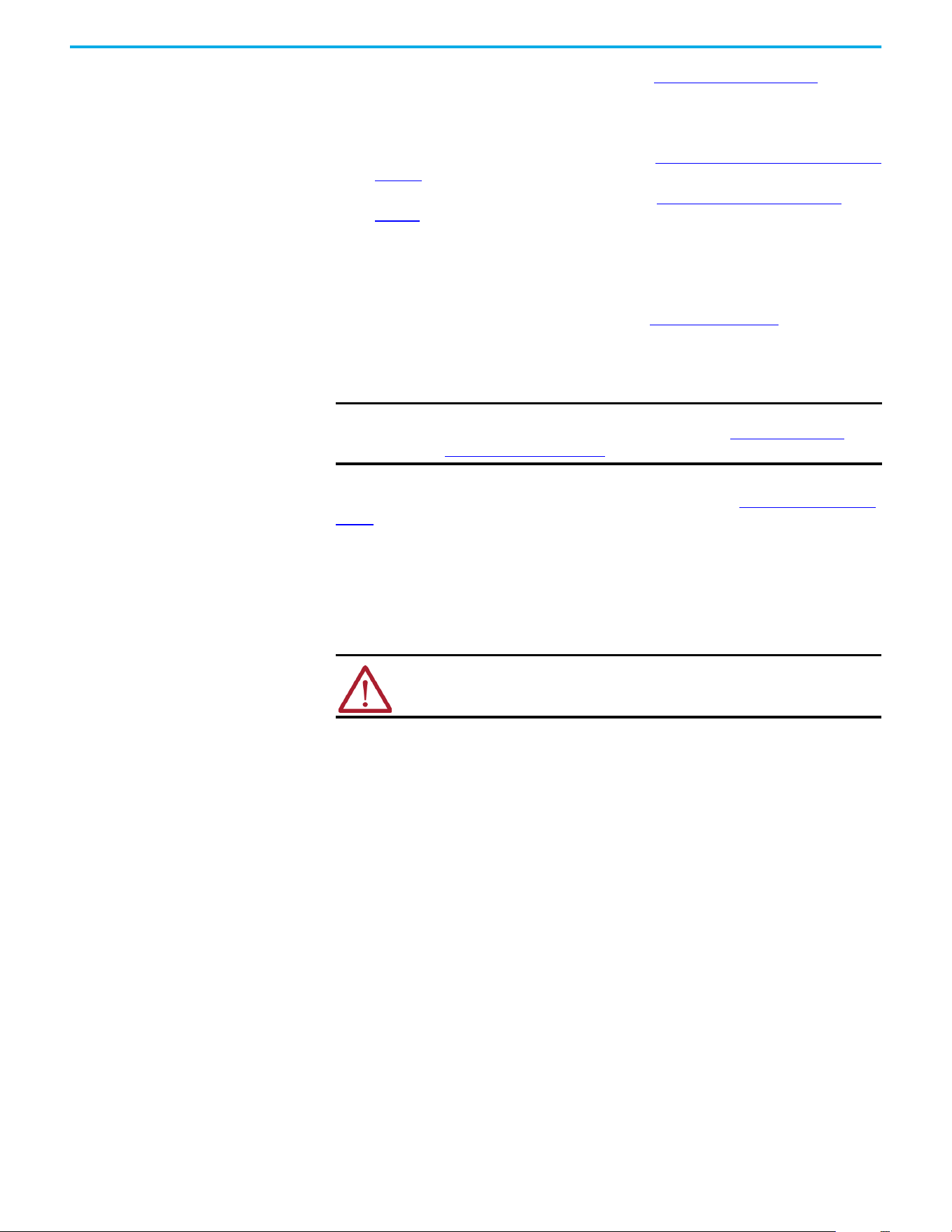
76 Rockwell Automation Publication 520-UM002E-EN-E - September 2024
Chapter 3 Configuring the PowerFlex 527 Drive with Integrated Motion
The LCD display begins the startup sequence. See Startup Sequence on page 45 for more
information.
3. When the startup sequence completes, verify that the MOD and NET status indicators are
steady green.
If the two status indicators are not solid green, see PowerFlex 527 Drive Status Indicators on
page 116 for more information.
4. Monitor the DC Bus voltage on the LCD display. See Real-time Information Display on
page 48 for more information.
If the DC Bus does not reach the expected voltage level, verify the 3-phase input power
connections. Also it can take as many as 1.8 seconds after input power is applied before the
drive can accept motion commands.
5. Verify that the axis state changes to STOPPED.
If the axis state does not change to STOPPED, see Fault Codes on page 111
.
Test and Tune the Axes –
Velocity and Position Control
Modes
This procedure assumes that you have configured your PowerFlex 527 drive, your Logix 5000
controller, and applied power to the system.
For help using the Logix Designer application as it applies to testing and tuning your axes with
ControlLogix EtherNet/IP modules or CompactLogix 5370 controllers, see Additional Resources on
page 8.
Test the Axes
Note: In the following example, the Axis Configuration is set to Position Loop.
Follow these steps to test the axes.
1. Verify that the load was removed from each axis.
2. In your Motion Group folder, right-click an axis and choose Properties.
The Axis Properties dialog box appears.
IMPORTANT Before proceeding with testing and tuning your axes, verify that the MOD and
NET status indicators are operating as described in PowerFlex 527 Drive
Status Indicators on page 116.
ATTENTION: Verify if drive I/O connection is in the running state and the axis is
in a stopped state.
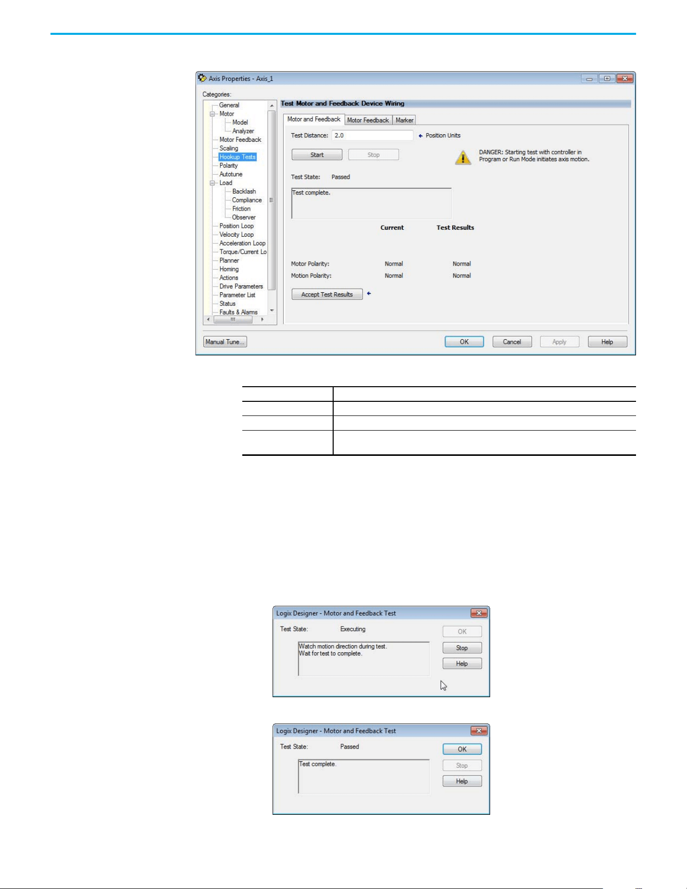
Rockwell Automation Publication 520-UM002E-EN-E - September 2024 77
Chapter 3 Configuring the PowerFlex 527 Drive with Integrated Motion
3. Select the Hookup Tests category.
4. In the Test Distance field, type 2.0 as the number of revolutions for the test.
5. Select the Motor Feedback tab.
6. Select Start.
7. Manually move the motor to the specific test distance. In this case, Step 4 dictated 2
revolutions.
8. Select the Motor and Feedback tab.
The Marker and Motor Feedback tests are not supported in Frequency Control mode.
9. Select Start.
The Logix Designer - Motor and Feedback Test dialog box appears. The Test State is
Executing. TESTING appears on the drive LCD display.
When the test completes successfully, the Test State changes from Executing to Passed.
10. Select OK.
Test Description
Marker Verifies marker detection capability as you rotate the motor shaft.
Motor Feedback Verifies feedback connections are wired correctly as you rotate the motor shaft.
Motor and Feedback
Verifies motor power and feedback connections are wired correctly as you command the
motor to rotate.
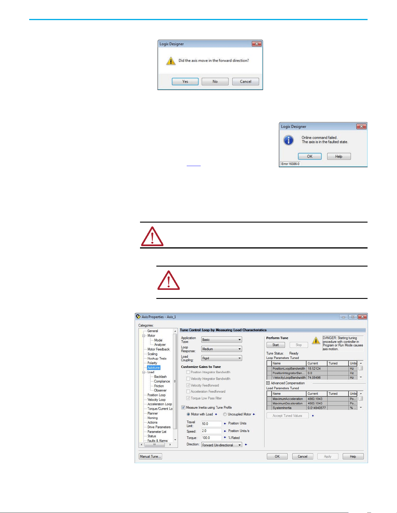
78 Rockwell Automation Publication 520-UM002E-EN-E - September 2024
Chapter 3 Configuring the PowerFlex 527 Drive with Integrated Motion
This dialog box appears asking if the direction was correct.
11. Select Yes.
12. Select Accept Test Results.
13. If the test fails, this dialog box appears.
Tune the Axes
Tuning the Axes is not applicable when using the Frequency Control method. Follow these steps to
tune the axes.
1. Verify that the load is still removed from the axis being tuned.
2. Select the Autotune category.
ATTENTION: Verify if drive I/O connection is in the running state and the axis is
in a stopped state.
ATTENTION: To reduce the possibility of unpredictable motor response,
tune your motor with the load removed first, then reattach the load and
perform the tuning procedure again to provide an accurate operational
response.
a. Select OK.
b. Verify the DC Bus voltage.
c. Verify unit values entered in the Scaling
category.
d. Return to step 9
and run the test again.
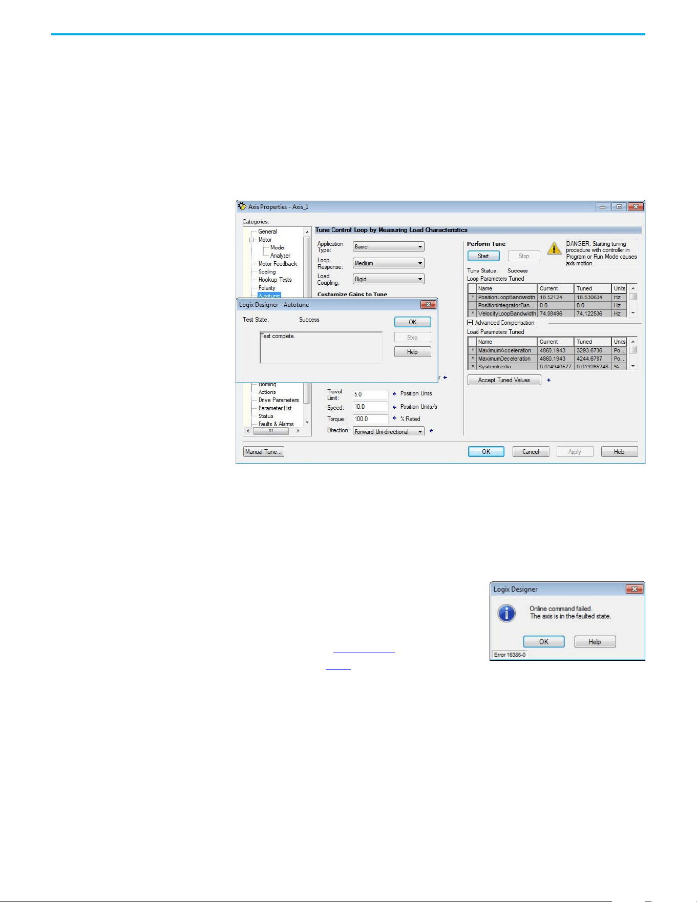
Rockwell Automation Publication 520-UM002E-EN-E - September 2024 79
Chapter 3 Configuring the PowerFlex 527 Drive with Integrated Motion
3. Type values for Travel Limit and Speed.
In this example, Travel Limit = 5 and Speed = 10. The actual value of programmed units
depending on your application.
4. From the Direction pull-down menu, choose a setting appropriate for your application.
The default setting is Forward Uni-directional.
5. Edit other fields as appropriate for your application.
6. Select Start.
The Logix Designer - Autotune dialog box appears. When the test completes, the Test State
changes from Executing to Success.
Tuned values populate the Loop and Load Parameters tables. Actual bandwidth values (Hz)
depend on your application and can require adjustment once motor and load are
connected.
7. Select Accept Tuned Values.
8. Select OK to close the Logix Designer - Autotune dialog box.
9. Select OK to close the Axis Properties dialog box.
10. If the test fails, this dialog box appears.
11. Repeat Test and Tune the Axes for each axis.
a. Select OK.
b. Make an adjustment to motor velocity.
c. See the Integrated Motion on the EtherNet/IP
Network: Configuration and Startup User Manual,
publication MOTION-UM003
for more information.
d. Return to step 6
and run the test again.

80 Rockwell Automation Publication 520-UM002E-EN-E - September 2024
Chapter 3 Configuring the PowerFlex 527 Drive with Integrated Motion
Notes:

Rockwell Automation Publication 520-UM002E-EN-E - September 2024 81
Chapter 4
Chapter
Chapter
PowerFlex 527 Integrated Safe Torque Off
This chapter introduces you to how the PowerFlex 527 integrated safe torque off feature meets the
requirements of Performance Level e (PLe), Category 3 according to EN ISO 13849, and SIL CL3
according to IEC 61508, EN 61800-5-2, and EN 62061.
Certification The TÜV Rheinland group has approved PowerFlex 527 drives with integrated safe torque off for
use in safety-related applications up to PLe, Category 3 according to EN ISO 13849, and SIL CL3
according to IEC 61508, EN 61800-5-2, and EN 62061, in which removing the motion-producing
power is considered to be the safe state.
See CE Conformity on page 36
for more information regarding certification.
Important Safety Considerations
The system user is responsible for the following:
• Validation of any sensors or actuators connected to the system
• Completing a machine-level risk assessment
• Certification of the machine to the desired EN ISO 13849 performance level or EN 62061 SIL
level
• Project management and proof testing performed in accordance with EN ISO 13849
Category 3 Requirements According to ISO 13849
Safety-related parts are designed with these attributes:
• A single fault in any of these parts does not lead to the loss of the safety function.
• A single fault is detected whenever reasonably practicable.
• Accumulation of undetected faults can lead to the loss of the safety function and a failure to
remove motion producing power from the motor.
Stop Category Definition
Stop category 0 as defined in EN 60204 or safe torque off as defined by EN 61800-5-2 is achieved
with immediate removal of motion-producing power to the actuator.
Performance Level (PL) and Safety Integrity Level (SIL)
For safety-related control systems, Performance Level (PL), according to EN ISO 13849, and SIL
levels, according to EN 61508 and EN 62061, include a rating of the system's ability to perform its
safety functions. All of the safety-related components of the control system must be included in
both a risk assessment and the determination of the achieved levels.
Refer to the EN ISO 13849, EN 61508, and EN 62061 standards for complete information on
requirements for PL and SIL determination.
IMPORTANT In the event of a malfunction, the most likely stop category is category 0.
When designing the machine application, timing and distance must be
considered for a coast to stop. For more information regarding stop
categories, see EN 60204-1.
82 Rockwell Automation Publication 520-UM002E-EN-E - September 2024
Chapter 4 PowerFlex 527 Integrated Safe Torque Off
Description of Operation The safe torque off (STO) feature provides a method, with sufficiently low probability of failure, to
force the power-transistor control signals to a disabled state. When the command to allow torque
ceases, all of the drive output-power transistors are released from the On state. This results in a
condition where the motor is coasting (stop category 0). Disabling the power transistor output does
not provide mechanical isolation of the electrical output that is required for some applications.
The PowerFlex 527 drive STO function response time is less than 12 ms. Response time is the delay
between the time the drive STO function receives the STO request and the time when motion
producing power is removed from the motor.
Probability of Dangerous
Failure Per Hour (PFH)
Safety-related systems are classified as operating in a High-demand/continuous mode where the
frequency of demands for operation made on a safety-related system is greater than once per
year.
The SIL value for a High-demand/continuous mode safety-related system is directly related to the
probability of a dangerous failure occurring per hour (PFH).
PFH Data
This PFH calculation is based on the equations from EN 61508 and show worst-case values.
Determination of safety parameters is based on the assumptions that the system operates in High-
demand mode and that the safety function is requested at least once a year.
Table 6
provides data for a 20-year proof test interval and demonstrates the worst-case effect of
various configuration changes on the data.
Safe Torque Off (STO)
Feature
The safe torque off circuit, when used with suitable safety components, provides protection
according to EN ISO 13849 (PLe), Category 3 or according to IEC EN 61508, EN 61800-5-2, and EN
62061 (SIL CL3). All components in the system must be chosen and applied correctly to achieve the
desired level of operator safeguarding.
The safe torque off circuit is designed to safely turn off all of the output-power transistors. You can
use the safe torque off circuit in combination with other safety devices to achieve the stop and
protection-against-restart as specified in IEC 60204-1.
IMPORTANT Determination of safety parameters is based on the assumptions that the
system operates in High-demand mode and that the safety function is
requested at least once every three months.
Table 6 - PFD and PFH Data
Attribute Value (Hardwired and Network)
PFD (average) 1.53E-4
PFH 1.91E-9
SIL CL 3
PL e
Category 3
MTTFd (years) 166
DCavg (%) 90 (medium)
HFT 1 (1oo2)
Mission time (years) 20
ATTENTION: This option is suitable only for performing mechanical work on the
drive system or affected area of a machine. It does not provide electrical safety.
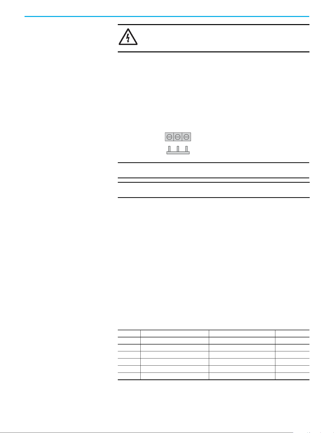
Rockwell Automation Publication 520-UM002E-EN-E - September 2024 83
Chapter 4 PowerFlex 527 Integrated Safe Torque Off
Safe Torque Off Feature Bypass
PowerFlex 527 drives do not operate without a safety circuit or safety bypass wiring. For
applications that do not require the safe torque off feature, you must install jumper wires to bypass
the safe torque off circuitry.
PowerFlex 527 drives ship with the safety control in the out-of-box state and with a safety bypass
jumper in place. In this configuration, the PowerFlex 527 safe torque off function is disabled.
Safe Torque Off Bypass Wiring
As-Shipped Safety Configuration
The PowerFlex 527 drive is shipped with:
• Safety control in out-of-box state
• Safety Bypass Jumper installed
In this configuration, the PowerFlex 527 safe torque off function is disabled.
Out-of-Box (OOB) Safety
State
The PowerFlex 527 drives ship in the out-of-box safety state.
Recognizing the Out-of-Box State
The safety control state can be read from the axis tag AxisSafetyState, or by using a MSG command
in the Logix Designer application to read the Safety Supervisor State.
If the state is “Waiting for TUNID” (8) or “Waiting for TUNID with Torque Permitted” (51), then the
safety control is in the out-of-box state.
SHOCK HAZARD: In safe torque off mode, hazardous voltages can still be
present at the drive. To avoid an electric shock hazard, disconnect power to the
system and verify that the voltage is zero before performing any work on the
drive.
IMPORTANT If safe torque off is not required, the drive must be returned to the as-
shipped safety configuration to allow operation.
IMPORTANT If the Safety Bypass Jumper is misplaced, it is acceptable to wire the S1, S2,
and S+ input terminals together.
S1 S2 S+
Safety Bypass Jumper
Hardwired Safety Inputs
Table 7 - Safety Supervisor State: Values
Value Definition Definition Mode
2 Idle No active connections Network
4 Executing Normal running state Network
7 Configuring Transition state Network
8 Waiting for TUNID Out-of-Box state Hardwired
51 Waiting for TUNID with Torque Permitted Out-of-Box state Hardwired
52 Executing with Torque Permitted STO Bypass state Network
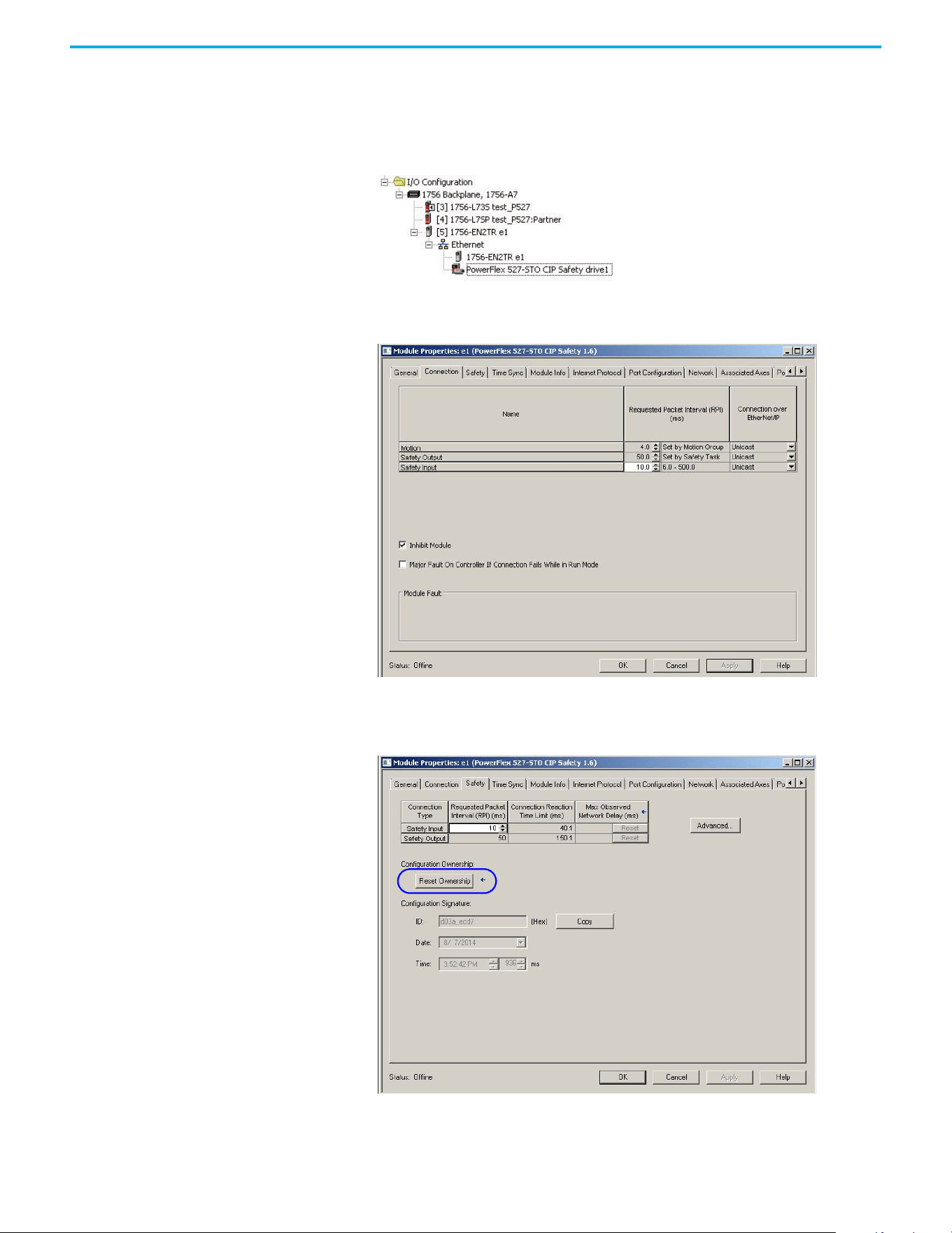
84 Rockwell Automation Publication 520-UM002E-EN-E - September 2024
Chapter 4 PowerFlex 527 Integrated Safe Torque Off
Restoring the Drive to the Out-of-Box State
After the integrated safety connection configuration is applied to the PowerFlex 527 drive at least
once, you can follow these steps to restore your PowerFlex 527 drive to the out-of-box state.
1. Right-click the PowerFlex 527 drive you created, and choose Properties.
Select the Connection tab.
The Connection tab appears.
2. Check Inhibit Module.
3. Select Apply, then select the Safety tab.
The Safety tab appears.
Rockwell Automation Publication 520-UM002E-EN-E - September 2024 85
Chapter 4 PowerFlex 527 Integrated Safe Torque Off
4. In the Configuration Ownership field, select Reset Ownership.
The safety connection must be inhibited before the reset is attempted. If any active
connection to the drive is detected, the reset is rejected.
5. Cycle drive power.
The drive is in the out-of-box state.
6. On power-up, make sure that the drive does not have a safety connection.
Safe Torque Off Status This section describes the safety-related status that is available to the motion controller.
Axis Tags
When a PowerFlex 527 Add-On-Profile (AOP) is added to a Logix I/O tree, Axis tags are added to the
controller tags.
Table 8
lists the safety-related STANDARD tags that are added when a new AXIS_CIP_DRIVE axis is
defined.
IMPORTANT Only authorized personnel should attempt Reset Ownership.
IMPORTANT If power to the drive is not cycled after step 4
, the drive does not
transition to the out-of-box state and maintains STO function.
IMPORTANT When the drive returns to the out-of-box state, the STO function
reverts to hardwired control.
ATTENTION: The status data described in this section is STANDARD data (not
SAFETY data) and may not be used as part of a safety function.
Table 8 - Safety-Related Axis Tags
Logix Designer Tag Name Attribute
[bit]
Type Description
AxisFault 34 DINT
GuardFaultStatus [5] BOOL STO Fault - Hardwired
SafetyFaultStatus [8] BOOL STO Fault - Network
GuardStatus
(1)
980 DINT
GuardOKStatus [0] BOOL Not STO Fault - Hardwired
GuardGateDriveOutputStatus [2] BOOL Torque Permitted - Hardwired
GuardStopInputStatus [3] BOOL Safety Inputs Enabled
GuardStopRequestStatus [4] BOOL Torque Disabled - Hardwired
GuardFault
(1)
981 DINT
GuardStopInputFault [9] BOOL STO Fault - Hardwired
GuardGateDriveFault [2] BOOL Internal STO Circuit Fault - Hardwired
CIPAxisFaultsRA 903 LINT
SafetyModuleCommunicationErrorFault [28] BOOL Loss of communications to Safety Control
CIPAxisAlarmsRA 904 LINT
SafetyModuleCommunicationErrorAlarm [28] BOOL Loss of communications to Safety Control
CIPInitializationFaultsRA 910 DINT
InvalidSafetyFirmwareFault [14] BOOL Invalid Safety Control Firmware
CIPStartInhibits 676 INT
SafeTorqueOffActiveInhibit [5] BOOL Torque Disabled - Network
CIPStartInhibitsRA 912 INT
SafeTorqueOffInhibit [5] BOOL Torque Disabled - Hardwired
AxisSafetyState 760 INT Safety Supervisor State
AxisSafetyStatus
(1)
761 DINT
86 Rockwell Automation Publication 520-UM002E-EN-E - September 2024
Chapter 4 PowerFlex 527 Integrated Safe Torque Off
Explicit Messages Explicit messages can be used to obtain additional diagnostic information from the safety control
using a MSG instruction.
Safety Supervisor State
The Safety Supervisor State provides information on the state of the CIP Safety connection and the
mode of operation.
Propose TUNID Blocked
The attribute Propose TUNID Blocked can be used to verify if the drive is in a state where it will
accept a safety connection. If the drive is enabled, it will not accept a safety connection.
SafetyFaultStatus [0] BOOL Status of SI.SafetyFault
SafetyResetRequestStatus [1] BOOL Status of SO.ResetRequest
SafetyResetRequiredStatus [2] BOOL Status of SI.ResetRequired
SafeTorqueOffActiveStatus [3] BOOL Status of SO.SafeTorqueOff
SafeTorqueDisabledStatus [4] BOOL Status of SI.TorqueDisabled
SafetyOutputConnectionClosed [30] BOOL 1 if all output connections are closed
SafetyOutputConnectionIdleStatus [31] BOOL 1 if output controller is in program mode
AxisSafetyFaults
(1)
763 DINT
SafetyCoreFault [1] BOOL Loss of communications to Safety Control
SafeTorqueOffFault [3] BOOL Status of SI.SafetyFault
(1) Bits not shown are always zero.
Table 8 - Safety-Related Axis Tags (Continued)
Logix Designer Tag Name Attribute
[bit]
Type Description
Safety Supervisor State: MSG
Parameter Value Description
Service Code 0x0E Get Attribute Single
Class 0x39 Safety Supervisor
Instance 1 —
Attribute 0x0B Device Status
Data Type SINT Unsigned Short Integer
Safety Supervisor State: Values
Value Definition Definition Mode
2 Idle No Active Connections Network
4 Executing Normal Running State Network
7 Configuring Transition State Network
8 Waiting for TUNID Out-of-Box State Hardwired
51
Waiting for TUNID
with Torque Permitted
Out-of-Box State Hardwired
52
Executing
with Torque Permitted
STO Bypass State Network
Propose TUNID Blocked: MSG
Parameter Value Description
Service Code 0x0E Get Attribute Single
Class 0x5A Safety Stop Functions
Instance 0 Class Attribute
Attribute 0x65 STO Mode
Data Type SINT Unsigned Short Integer
Rockwell Automation Publication 520-UM002E-EN-E - September 2024 87
Chapter 4 PowerFlex 527 Integrated Safe Torque Off
Safe Torque Off Mode
The attribute STO Mode can be used to verify if the PowerFlex 527 is in STO Bypass Mode.
Safe Torque Off Faults
When a safety fault is indicated in any of the following tags:
•SI.SafetyFault
• Axis.SafetyFaultStatus
• Axis.SafetyTorqueOffFault
The cause of the fault can be read using an explicit message.
Safe Torque Off Mode: Values
Value Definition
0 Accept a Safety Connection
1Block a Safety Connection
Safe Torque Off Mode: MSG
Parameter Value Description
Service Code 0x0E Get Attribute Single
Class 0x5A Safety Stop Functions
Instance 1 Axis Number
Attribute 0x104 STO Mode
Data Type SINT Unsigned Short Integer
Safe Torque Off Mode: Values
Value Definition
1Normal Operation
2 STO Bypass Mode
Safe Torque Off Fault Type: MSG
Parameter Value Description
Service Code 0x0E Get Attribute Single
Class 0x5A Safety Stop Functions
Instance 1 Axis Number
Attribute 0x108 STO Fault Type
Data Type SINT Unsigned Short Integer
Safe Torque Off Fault Type: Values
Value Definition
1No Fault
3 Circuit Error
102 Hardwired Input Discrepancy
104 Hardwired Input in Network Mode

88 Rockwell Automation Publication 520-UM002E-EN-E - September 2024
Chapter 4 PowerFlex 527 Integrated Safe Torque Off
Notes:
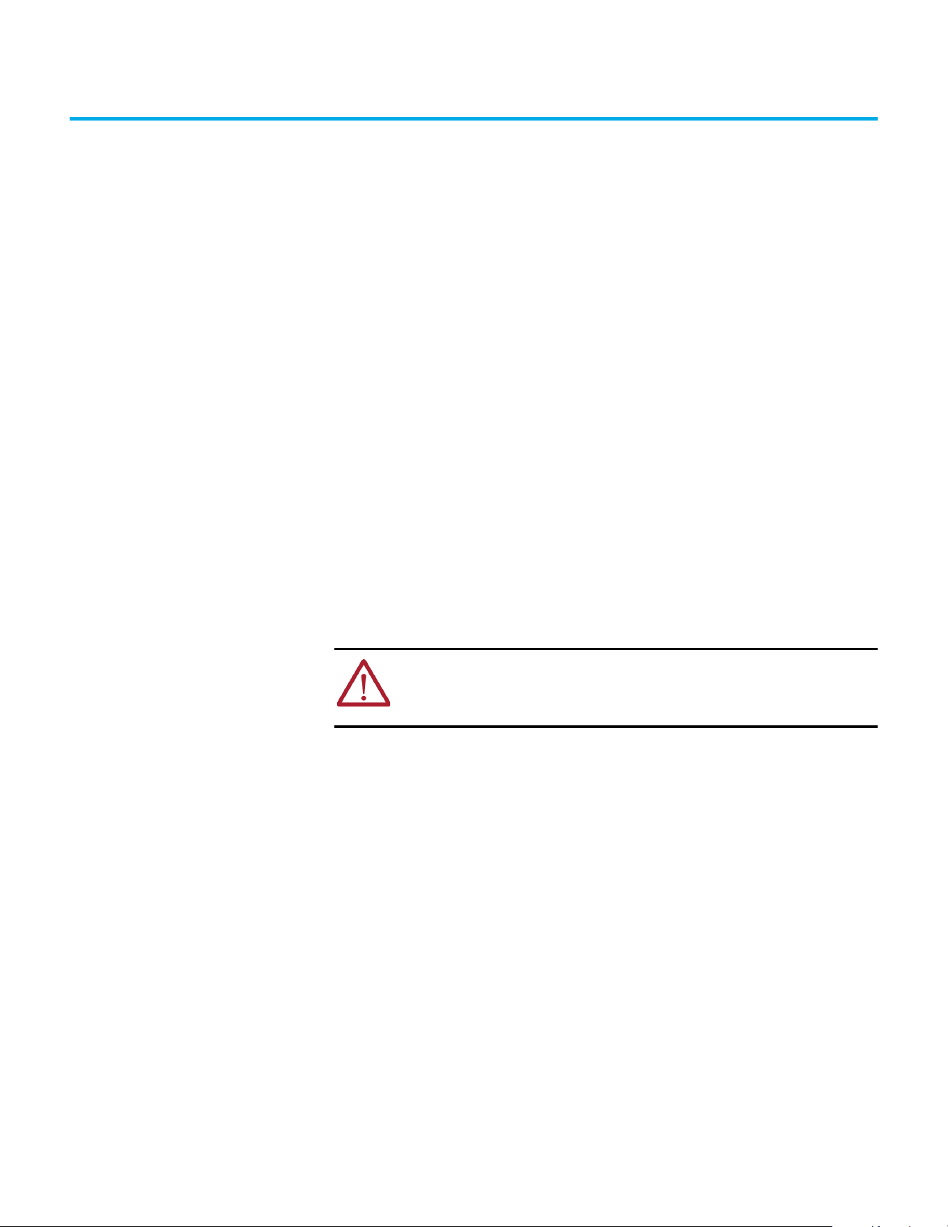
Rockwell Automation Publication 520-UM002E-EN-E - September 2024 89
Chapter 5
Hardwired Control of Safe Torque Off
This chapter introduces you to how the PowerFlex 527 integrated safe torque off feature is
configured for hardwired control of safe torque off.
Description of Operation The safe torque off feature provides a method, with sufficiently low probability of failure, to force
the power-transistor control signals to a disabled state. If either hardwired safety input is de-
energized, all drive output-power transistors are released from the On state. This results in a
condition where the drive is coasting (stop category 0). Disabling the power transistor output does
not provide mechanical isolation of the electrical output that is required for some applications.
Selection of Hardwired Safe Torque Off
To select hardwired control of safe torque off (STO):
• The safety control must be in the out-of-box state.
• The Safety Bypass Jumper must be removed.
• An appropriate safety device must be connected to terminals S1, S2, and 01 (Digital
Common).
Operation of Hardwired Safe Torque Off
Under normal operation, the safe torque off inputs are energized. If either of the safety enable
inputs are de-energized, then all output power transistors turn off. The safe torque off response
time is less than 12 ms.
ATTENTION: If any of the safety enable inputs de-energize, the Start Inhibit field
indicates SafeTorqueOffInhibit and the GuardStopRequestStatus bit of the axis
GuardStatus tag are set to 1. Both inputs must be de-energized within 1 second
and re-energized within 1 second to avoid GuardStopInputFault conditions.
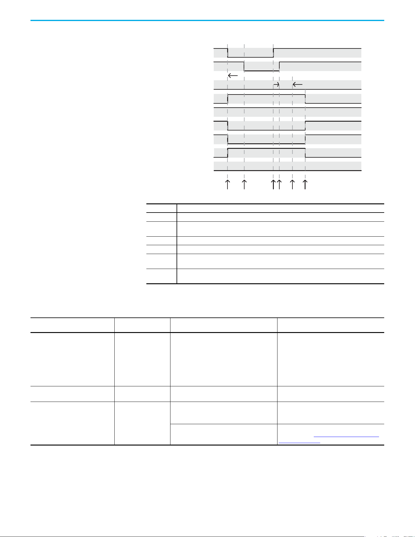
90 Rockwell Automation Publication 520-UM002E-EN-E - September 2024
Chapter 5 Hardwired Control of Safe Torque Off
System Operation when Inputs are Meeting Timing Requirements
Troubleshoot the Safe Torque Off Function
Event Description
1 At least one input is switched off. GuardStopRequestStatus bit is set to 1.
2
Second input is switched off within 1 second. This must always occur within 1 second to help prevent a
GuardStopInputFault condition.
3 First input is switched on.
4 Second input is switched on within 1 second of event 3.
5
Both inputs are in the ON state simultaneously within 1 second. As a result, the GuardStopInputFault is
not posted.
6
The GuardStopRequestStatus bit is set back to 0 if both inputs are in the ON state for 100 ms
continuously (100 ms debounce time).
(Safety Input) S1
13456
Start Permitted
OK
Permit Torque
Torque Permitted
Torque Permitted
(Safety Input) S2
GuardFault
SafeTorqueOInhibit
GuardOKStatus
GuardGateDriveOutputStatus
GuardStopInputStatus
GuardStopRequestStatus
GuardStopInputFault
2
100 ms Debounce Time
1 second Discrepancy Limit
Start Inhibit
Torque Disabled
Disable Torque
No Fault
No Fault
Torque Disabled
PowerFlex 527 Drive Troubleshooting
Exception Code on Drive Display
Fault Message
Logix Designer
Problem Possible Solutions
SAFE FLT S09 - SS IN GuardStopInputFault
Safe torque off function mismatch. System does not
allow motion. Safe torque off mismatch is detected
when safety inputs are in a different state for more
than 1.0 second.
• Verify safety wiring and connections:
– Wire terminations at safe torque off (STO)
connector
– Cable/header not seated correctly
– +24V power
• Check state of safety inputs.
• Reset error and run proof test.
• Return drive for repair if fault continues.
SAFE FLT S01 - GUARD INTERNALFAULT
CPUWatchdogFault
(1)
Drive safety diagnostic detected internal STO design
failure.
• Cycle power.
• Return drive for repair if fault continues.
SAFE FLT S03 - GUARD GATE DRIVE FAULT
SafeTorqueOffFault
(2)
Drive safety diagnostic detected internal STO design
failure.
• Cycle power.
• Execute STO function.
• Return drive for repair if fault continues.
Hardwired safe torque off input energized when
drive is in network safety mode.
Reset the drive to out-of-box settings, hardwired
safety mode. See Restoring the Drive to the Out-of-
Box State on page 84 for instructions.
(1) Displayed in the LCD display as Module Fault.
(2) Displayed in the LCD display as Safety Fault.
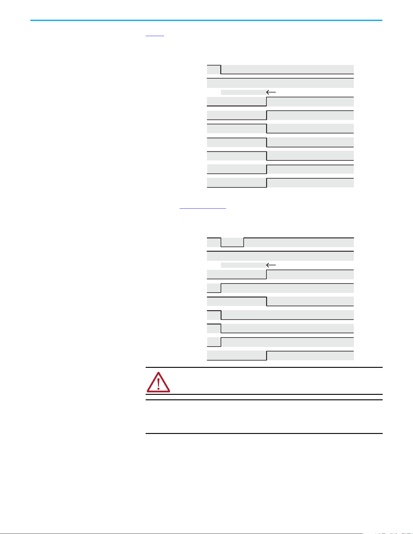
Rockwell Automation Publication 520-UM002E-EN-E - September 2024 91
Chapter 5 Hardwired Control of Safe Torque Off
Figure 1 demonstrates when the safe torque off mismatch is detected and a GuardStopInputFault is
posted.
Figure 1 - System Operation in the Event that the Safety Enable Inputs Mismatch
When one safety input is turned off, the second input must also be turned off, otherwise a fault is
asserted (See Figure 2 on page 91). The fault is asserted even if the first safety input is turned on
again.
Figure 2 - System Operation in the Event that the Safety Enable Inputs Mismatch Momentarily
ATTENTION: The safe torque off fault is detected upon demand of the safe
torque off function. After troubleshooting, a safety function must be executed to
verify correct operation.
IMPORTANT The safe torque off fault can be reset only if both inputs are in the Off state
for more than 1 second. After the fault reset requirement is satisfied, an
MASR command in the Logix Designer application must be issued to reset
the GuardFault and GuardStopInputFault conditions.
(Safety Input) S1
1 second Discrepancy Limit
No Fault Faulted
No Fault Faulted
Start Inhibited
OK Not OK
Torque Disabled
Stop Requested
Start Permitted
Torque Permitted
(Safety Input) S2
GuardFault
SafeTorqueOInhibit
GuardOKStatus
GuardGateDriveOutputStatus
GuardStopInputStatus
GuardStopRequestStatus
GuardStopInputFault
(Safety Input) S1
1 second
Start Inhibit
Torque Disabled
Torque Disabled
(Safety Input) S2
GuardFault
SafeTorqueOInhibit
GuardOKStatus
GuardGateDriveOutputStatus
GuardStopInputStatus
GuardStopRequestStatus
GuardStopInputFault
92 Rockwell Automation Publication 520-UM002E-EN-E - September 2024
Chapter 5 Hardwired Control of Safe Torque Off
Safe Torque Off Connector
Data
PowerFlex 527 terminals S1, S2, and 01 are used for hardwired control of safe torque off.
Terminals for Safe Torque Off (STO) Connection
Wire the Safe Torque Off
Circuit
This section provides guidelines for wiring safe torque off connections to your PowerFlex 527 drive.
Safe Torque Off Wiring Requirements
The safe torque off (STO) connection wire must be copper with 75 °C (167 °F) minimum rating.
Safe Torque Off (STO) Connector Pinouts Control
STO Pin Signal Description
01 Digital Common
The return for digital I/O. It is electrically isolated (along with the digital inputs
and encoder power) from the rest of the drive.
S1 Safety 1 Safety input 1.
S2 Safety 2 Safety input 2.
S+ Safety +24V
+24V supply for safety circuit. This is internally tied to the +24V DC source
(terminal 11).
IMPORTANT Digital Common (terminal 01) is common for the digital inputs, the safety
inputs, and the encoder power supply (optional).
R1
11 12 13 14 15 16 17
R2 R5 R6 01 02 03 04 05 06 07
S1 S2 S+
Safety Bypass Jumper
Hardwired Safety Inputs
IMPORTANT The National Electrical Code and local electrical codes take precedence over
the values and methods provided.
IMPORTANT Pin S+ (Safety +24V) is used to disable the safe torque off function.
When wiring to the STO connector, use an external 24V supply for the
external safety device that triggers the safe torque off request. To avoid
jeopardizing system performance, do not use pin S+ as a power supply for
the external safety device.
IMPORTANT The National Electrical Code and local electrical codes take precedence over
the values and methods provided.
IMPORTANT Stranded wires must terminate with ferrules to help prevent short circuits,
per table D.7 of EN ISO 13849-2.
Safe Torque Off (STO) Terminal Wiring
Maximum Wire Size
(1)
(1) Maximum and minimum sizes that the terminal block will accept. These are not recommended wire sizes.
Minimum Wire Size
(1)
Torque
1.3 mm
2
(16 AWG) 0.13 mm
2
(26 AWG)
0.71…0.86 N•m (6.2…7.6 lb•in)
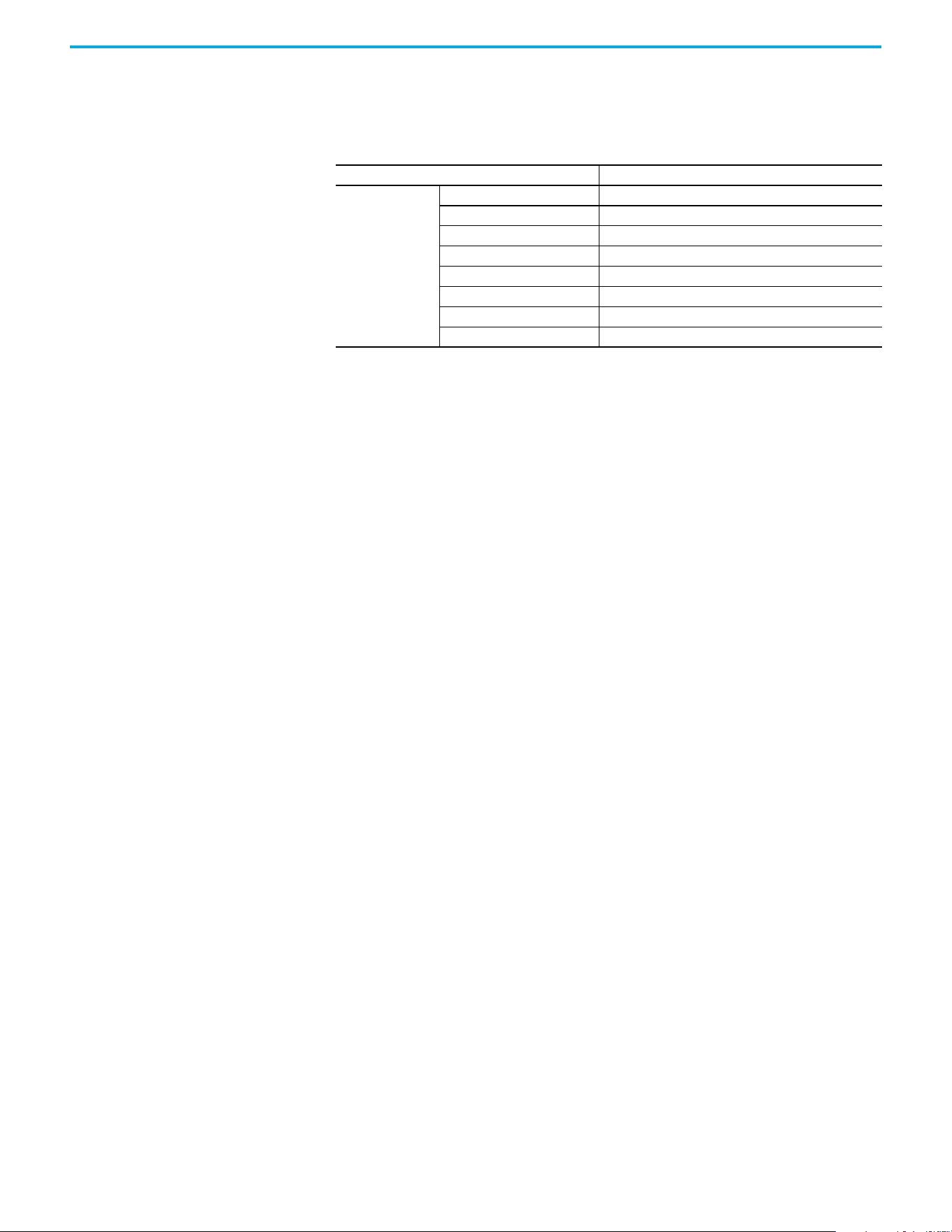
Rockwell Automation Publication 520-UM002E-EN-E - September 2024 93
Chapter 5 Hardwired Control of Safe Torque Off
Safe Torque Off
Specifications
To maintain their safety rating, PowerFlex 527 drives must be installed inside protected control
panels or cabinets appropriate for the environmental conditions of the industrial location. The
protection class of the panel or cabinet must be IP54 or higher.
Safe Torque Off Signal Specifications
Attribute Value
Safety inputs
(per channel)
Input current < 10 mA
Input ON voltage, max 18…26.4V DC
Input OFF voltage, max 5V DC
Input ON current 10 mA
Input OFF current 500 µA
Pulse rejection width 700 µs
External power supply SELV/PELV
Input type Optically isolated and reverse voltage protected

94 Rockwell Automation Publication 520-UM002E-EN-E - September 2024
Chapter 5 Hardwired Control of Safe Torque Off
Notes:

Rockwell Automation Publication 520-UM002E-EN-E - September 2024 95
Chapter
Chapter 6
Network Control of Safe Torque Off
This chapter describes network control of the safe torque off function. This example uses a
1756-L7xS GuardLogix safety controller to issue the safe torque off (STO) command over the
EtherNet/IP network and the PowerFlex 527 drive executes the STO command.
Compatible Safety Controllers
The Studio 5000 Logix Designer application:
• Version 24.00 or later, provides support for programming, commissioning, and maintaining
the 1756-L7xS GuardLogix safety controller.
• Version 28.00 or later, provides support for programming, commissioning, and maintaining
the Compact GuardLogix 5370 safety controller.
A 1756-L7xS GuardLogix or Compact GuardLogix 5370 safety controller is required for network
control of the PowerFlex 527 safe torque off function.
The PowerFlex 527 safety connection can originate from a safety controller that provides both
safety and motion control.
The PowerFlex 527 safety connection can originate from a safety controller that controls only the
safety, while a separate Logix processor controls motion.
Selection of Network Safe Torque Off
To select network control of safe torque off:
1. The PowerFlex 527 drive must be added to a 1756-EN2T, 1756-EN2TR, 1756-EN2F, 1756-EN3T,
or 1756-EN3TR EtherNet/IP bridge in a 1756-L7xS GuardLogix controller I/O tree.
2. The 1756-EN2T, 1756-EN2TR, 1756-EN2F, 1756-EN3T, or 1756-EN3TR EtherNet/IP bridge must
be configured for “Safety Only” or “Motion and Safety”.
3. Download the new configuration to the controller.
The drive display may show fault code “SAFE FLT S03 - GUARD GATE DRIVE FAULT”.
4. Turn off incoming power to the drive.
5. Remove the Safety Bypass jumper.
6. Turn on incoming power to the drive.
Any display fault should now be cleared.
Safety Application Requirements
Creating, recording, and verifying the safety signature is also a required part of the safety
application development process. Safety signatures are created by the safety controller. The safety
signature consists of an identification number, date, and time that uniquely identifies the safety
portion of a project. This signature covers all safety logic, data, and safety I/O configuration.
For safety system requirements, including information on the safety network number (SNN),
verifying the safety signature, and functional verification tests, see the GuardLogix 5570 and
Compact GuardLogix 5370 Reference Manual, publication 1756-RM099
.
IMPORTANT You must read, understand, and fulfill the requirements that are detailed in
this publication before operating a safety system that uses a GuardLogix
controller and PowerFlex 527 drive.

96 Rockwell Automation Publication 520-UM002E-EN-E - September 2024
Chapter 6 Network Control of Safe Torque Off
Network Safe Torque Off Specifications
Safe Torque Off Assembly Tags
With network control, a 1756-L7xS GuardLogix safety controller controls the PowerFlex STO function
through the SO.SafeTorqueOff tag in the safety output assembly.
The SO.Command tags are sent from the GuardLogix safety output assembly to the PowerFlex 527
to control the safe torque off function.
The SI.Status tags are sent from the PowerFlex 527 to the GuardLogix safety input assembly and
indicate the PowerFlex 527 safety control status.
The SI.ConnectionStatus tags indicate the status of the safety input connection.
Table 9
lists the SAFETY tags added to the controller tags when a PowerFlex 527 drive is added to a
GuardLogix I/O configuration and the connection is configured for “Motion and Safety” or for “Safety
only”.
Safe Torque Off Network Specifications
Attribute Value
Safety connection RPI, minimum 6 ms
Input assembly connections 1
Output assembly connections 1
Integrated safety open request support Type 1 and Type 2 requests
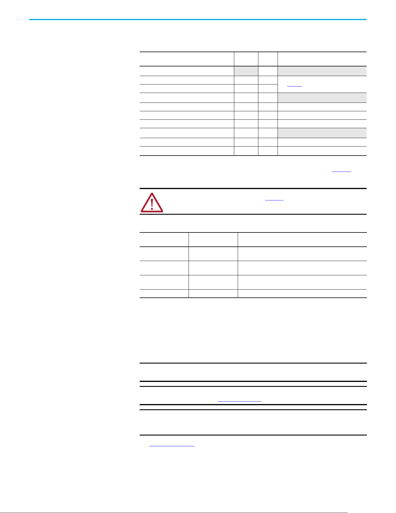
Rockwell Automation Publication 520-UM002E-EN-E - September 2024 97
Chapter 6 Network Control of Safe Torque Off
The “Attribute” values that are listed are the Assembly Object attribute values.
STO Fault Reset
If a PowerFlex 527 drive safety control detects a fault, the input assembly tag SI.SafetyFault is set
to 1. A transition from logic 0 to 1 of the SO.Reset tag is required after the SO.SafeTorqueOff tag has
transitioned from logic 0 to 1.
To reset Axis.SafetyFault, a MAFR command must be issued.
See Figure 3 on page 98 for an understanding of the PowerFlex 527 STO Fault reset functionality.
Table 9 - Safe Torque Off Assembly Tags
Logix Designer Tag Name
Attribute
[bit]
Type Description
SI.ConnectionStatus
(1)(2)
(1) Bits not listed are always zero.
(2) ConnectionStatus is determined by the Safety Validator in the GuardLogix controller. For more information, see the Safety
Connection Status table in the GuardLogix 5570 and Compact GuardLogix 5370 Reference Manual, publication 1756-RM099
.
DINT
SI.RunMode [0] BOOL
See Table 10
.
SI.ConnectionFaulted [1] BOOL
SI.Status
(1)(3)
(3) The Status is sent from the drive to the controller using the CIP Safety protocol.
0x1A0 SINT
SI.TorqueDisabled [0] BOOL 0 = Torque Permitted; 1 = Torque Disabled
SI.SafetyFault [6] BOOL 1 = STO Fault present
SI.ResetRequired [7] BOOL 1 = A reset is required
SO.Command
(1)(4)
(4) The Command is sent from the controller to the drive using the CIP Safety protocol.
0x180 SINT
SO.SafeTorqueOff [0] BOOL 0 = Disable Permit; 1 = Permit Torque
SO.Reset [7] BOOL
0→1 = Reset STO Fault
ATTENTION: Only data that is listed in Table 10 is SAFETY data with SIL 3
integrity.
Table 10 - Safety Connection Status
RunMode Status
ConnectionFaulted
Status
Safety Connection Operation
1 = Run 0 = Valid
Data is actively being controlled by the producing device. The
producing device is in Run mode.
0 = Idle 0 = Valid
The connection is active and the producing device is in the Idle
state. The safety data is reset to zero.
0 = Idle 1 = Faulted
The safety connection is faulted. The state of the producing device
is unknown. The safety data is reset to zero.
11Invalid state.
IMPORTANT Transition of the SO.SafeTorqueOff tag to logic 1 must always be executed
before transition of the SO.Reset tag to logic 1.
IMPORTANT PowerFlex 527 drives enter the STO Fault state if any STO function fault is
detected. See Table 11 on page 98
for integrated safety troubleshooting.
IMPORTANT An STO Fault sets the Axis.SafetyFault tag. After the STO Fault is reset, a
MAFR command must be issued by the motion controller to clear the
Axis.SafetyFault tag to enable motion.
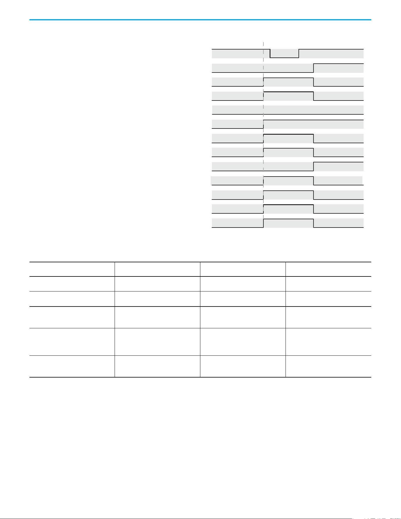
98 Rockwell Automation Publication 520-UM002E-EN-E - September 2024
Chapter 6 Network Control of Safe Torque Off
Figure 3 - Reset Safe Torque Off Fault Diagram
Troubleshoot Network Safe Torque Off
Drv:SO.SafeTorqueO
Disable Torque Permit Torque
Faulted
SO.ResetRequest
No Fault
No Fault
No Fault
Faulted (cleared by MAFR)
No Fault
Start Inhibited
Reset Not Required
Reset Not Required Reset Required
Torque Disabled
Start Permitted
Torque Permitted
Torque Disabled
Torque Permitted
Drv:SO.ResetRequest
Drv:SI.TorqueDisabled
Drv:SI.SafetyFault
DrvSI:ResetRequired
Axis.SafetyFault
Axis.SafeTorqueOActiveInhibit
Axis.SafetyFaultStatus
Axis.SafetyResetRequestStatus
Axis.SafetyResetRequiredStatus
Axis.SafeTorqueOActiveStatus
Axis.SafeTorqueODisabledStatus
Axis.SafeTorqueOFault
Permit Torque Disable Torque
Table 11 - PowerFlex 527 Drive Troubleshooting
Exception Code on Drive Display
Fault Message
Logix Designer
Problem Possible Solutions
SAFE FLT S01 - GUARD INTERNAL FAULT
CPUWatchDogFault
(1)
Drive safety diagnostic detected internal
STO design failure.
• Cycle power.
• Return drive for repair if fault continues.
FLT AXIS FLT M28 - SAFETY COMM
SafetyModuleCommunicationErrorFault
(1)
Drive safety diagnostic detected internal
STO design failure.
• Cycle power.
• Return drive for repair if fault continues.
SAFE FLT S03 - GUARD GATE DRIVE FAULT
(STO Fault Type = 3)
SafeTorqueOffFault
(2)
Drive safety diagnostic detected internal
STO design failure
• Cycle power.
• Execute STO function.
• Return drive for repair if fault continues.
SAFE FLT S03 - GUARD GATE DRIVE FAULT
(STO Fault Type = 104)
SafeTorqueOffFault
(2)
Hardwired input energized in network
mode.
• Remove power.
• Remove any connection to hardwired
safety inputs.
• Restore power.
INIT FLT M14 - INVALID SAFETY FIRMWARE
InvalidSafeyFirmwareFault
(2)
The safety firmware is not compatible with
the drive firmware, or the main safety
firmware is missing.
• Cycle power.
• Upgrade drive firmware.
• Return drive for repair if fault continues.
(1) Displayed in the LCD display as Module Fault.
(2) Displayed in the LCD display as Safety Fault.
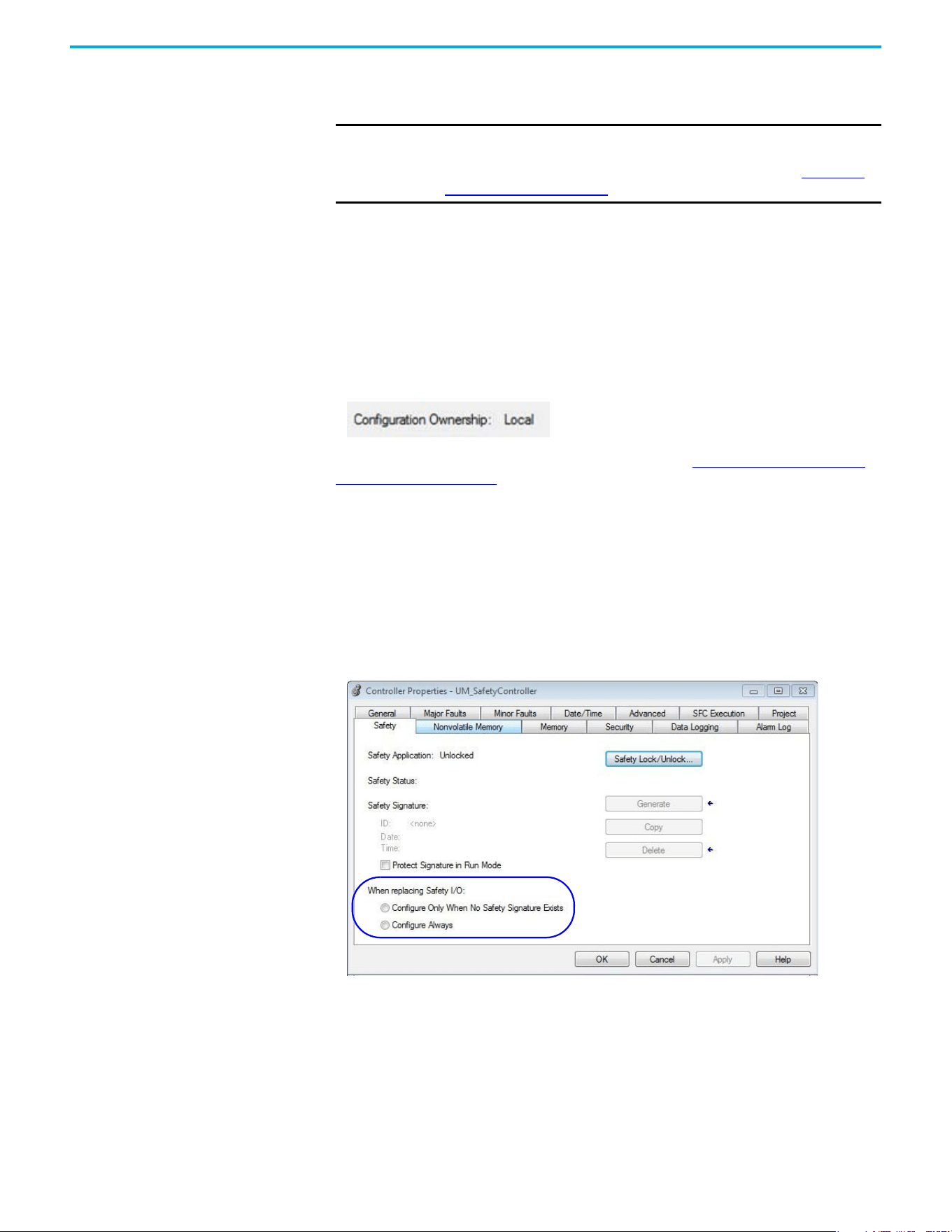
Rockwell Automation Publication 520-UM002E-EN-E - September 2024 99
Chapter 6 Network Control of Safe Torque Off
Understanding Integrated
Safety Drive Replacement
GuardLogix controllers retain I/O device configuration onboard and are able to download the
configuration to the replacement device.
Replacing a PowerFlex 527 drive that sits on an integrated safety network is more complicated
than replacing standard devices because of the Safety Network Number (SNN). The device number
and SNN make up the safety device's DeviceID. Safety devices require this more complex identifier
to make sure that duplicate device numbers do not compromise communication between the
correct safety devices. The SNN is also used to provide integrity on the initial download to the
PowerFlex 527 drive.
When the Logix Designer application is online, the Safety tab of the Module Properties dialog box
displays the current configuration ownership. When the opened project owns the configuration,
Local is displayed.
A communication error is displayed if the module read fails. See Replacing an Integrated Safety
Drive in a GuardLogix System for integrated safety drive replacement examples.
Replacing an Integrated
Safety Drive in a GuardLogix
System
If you are relying on a portion of the integrated safety system to maintain SIL 3 behavior during
drive replacement and functional testing, do not use the Configure Always feature.
Use the Configure Always feature when you are not relying on the entire routable integrated safety
control system to maintain PLe/SIL 3 behavior during the replacement and functional testing of a
PowerFlex 527 drive. Drive replacement is configured on the Safety tab of the GuardLogix
controller.
Setting the SNN with a GuardLogix Controller
Replacement with “Configure Only When No Safety Signature Exists”
Enabled
When a PowerFlex 527 drive is replaced and the DeviceID of the new drive matches the original, you
can download the configuration from the safety controller. The DeviceID is a combination of the
node/IP address and the safety network number (SNN), and is updated whenever the SNN is set.
IMPORTANT If the replacement PowerFlex 527 drive was used previously, clear its
existing configuration before installing it on a safety network by resetting
the drive to its out-of-box condition. To see how this is done, see Out-of-Box
(OOB) Safety State on page 83.
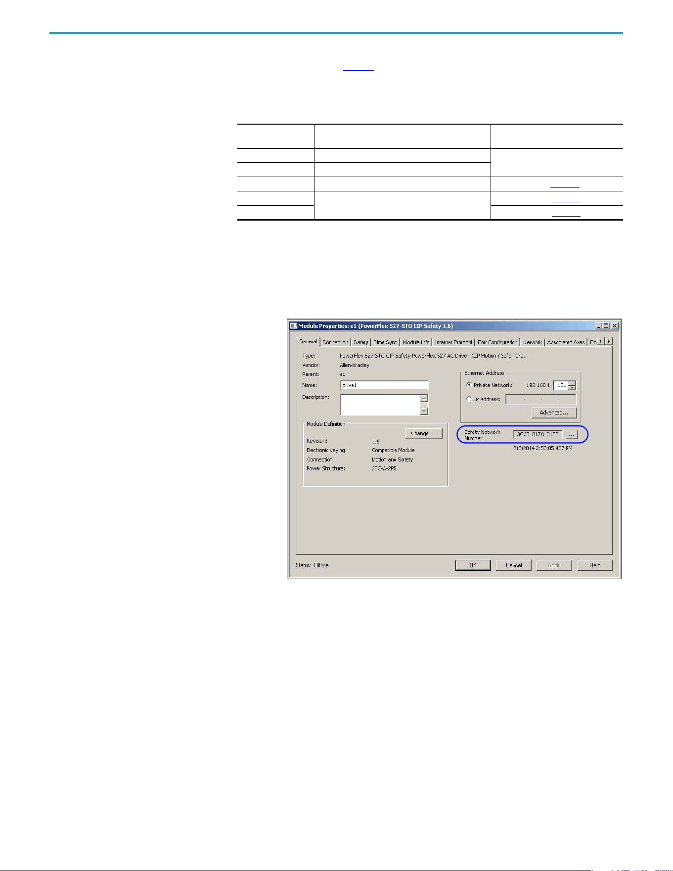
100 Rockwell Automation Publication 520-UM002E-EN-E - September 2024
Chapter 6 Network Control of Safe Torque Off
If the project is configured as Configure Only When No Safety Signature Exists, follow the
appropriate instructions in Table 12 to replace a PowerFlex 527 drive based on your scenario. Once
you have completed the steps correctly and the DeviceID matches the original, the safety controller
can download the proper drive configuration and re-establish the safety connection.
Scenario 1 – Replacement Integrated Safety Drive Is Out-of-Box and Safety Signature
Exists
1. Remove and replace the existing integrated safety drive.
2. Right-click the replacement drive and choose Properties.
The General tab appears in the Module Properties dialog box.
Table 12 - Replacing a PowerFlex 527 Drive
GuardLogix Safety
Signature Exists
GuardLogix Safety Signature Exists Action Required
No No SNN (out-of-box)
None. The module is ready for use.
Yes or No Same SNN as original safety task configuration
Yes No SNN (out-of-box) See Scenario 1 on page 100
.
Yes
Different SNN than original safety task configuration
See Scenario 2 on page 102
.
No See Scenario 3 on page 104
.
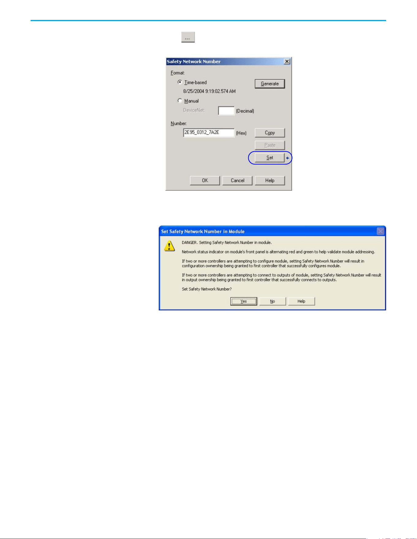
Rockwell Automation Publication 520-UM002E-EN-E - September 2024 101
Chapter 6 Network Control of Safe Torque Off
3. Select to the right of the Safety Network Number (SNN).
The Safety Network Number dialog box appears.
4. Select Set.
5. Verify that the Network Status (NET) status indicator is alternating red/green on the correct
drive.
6. Select Yes to set the SNN and accept the replacement drive.
7. Power cycle the drive.
8. Follow your company-prescribed procedures to functionally test the replacement drive and
system and to authorize the system for use.
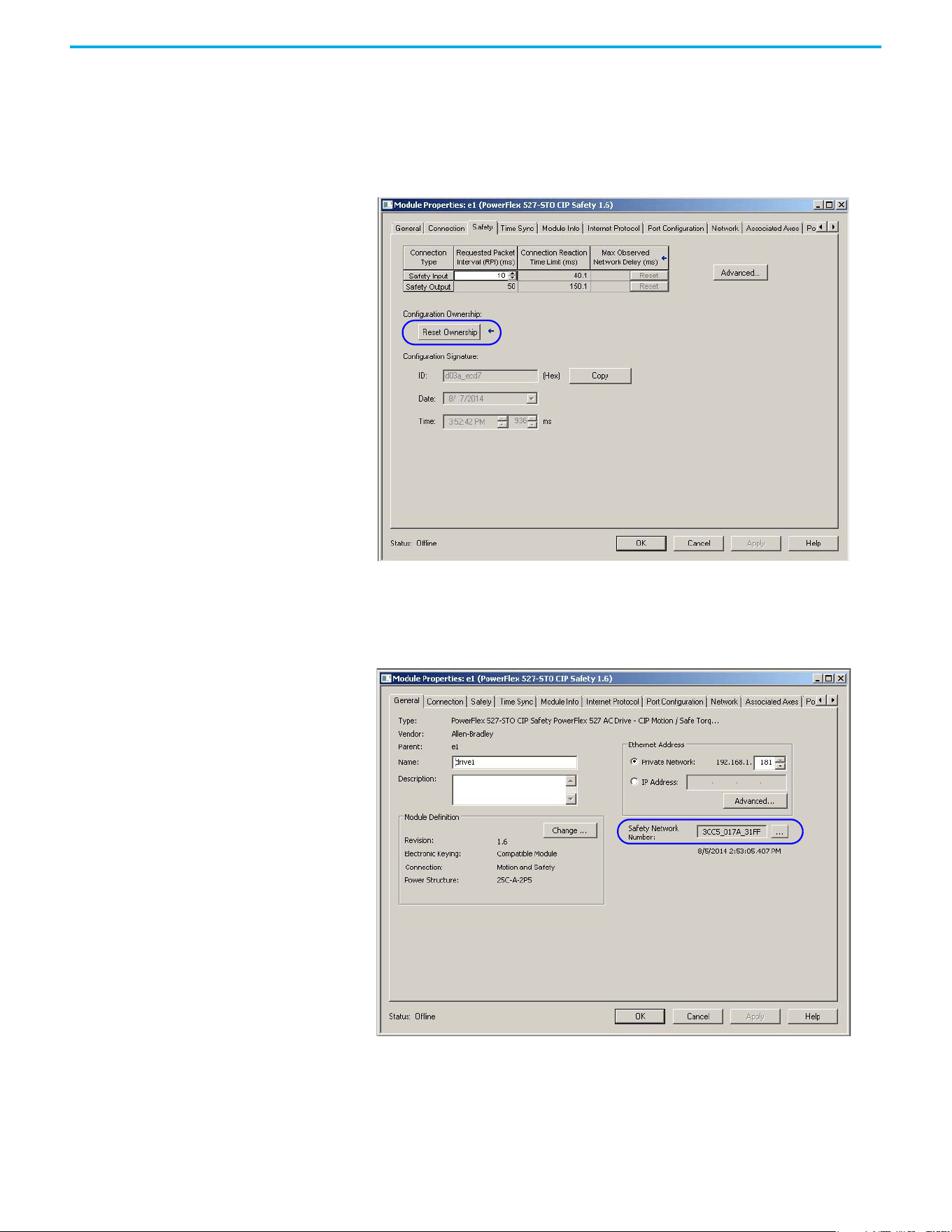
102 Rockwell Automation Publication 520-UM002E-EN-E - September 2024
Chapter 6 Network Control of Safe Torque Off
Scenario 2 – Replacement Integrated Safety Drive SNN is Different from Original and
Safety Signature Exists
1. Remove and replace the existing integrated safety drive.
2. Right-click the replacement drive and choose Properties.
3. Select the Safety tab.
4. Select Reset Ownership.
5. Select OK.
6. Right-click the replacement drive and chooses Properties.
The General tab appears in the Module Properties dialog box.

Rockwell Automation Publication 520-UM002E-EN-E - September 2024 103
Chapter 6 Network Control of Safe Torque Off
7. Select to the right of the Safety Network Number (SNN).
The Safety Network Number dialog box appears.
8. Select Set.
9. Verify that the Network Status (NET) status indicator is alternating red/green on the correct
drive.
10. Power cycle the drive.
11. Follow your company-prescribed procedures to functionally test the replacement drive and
system and to authorize the system for use.
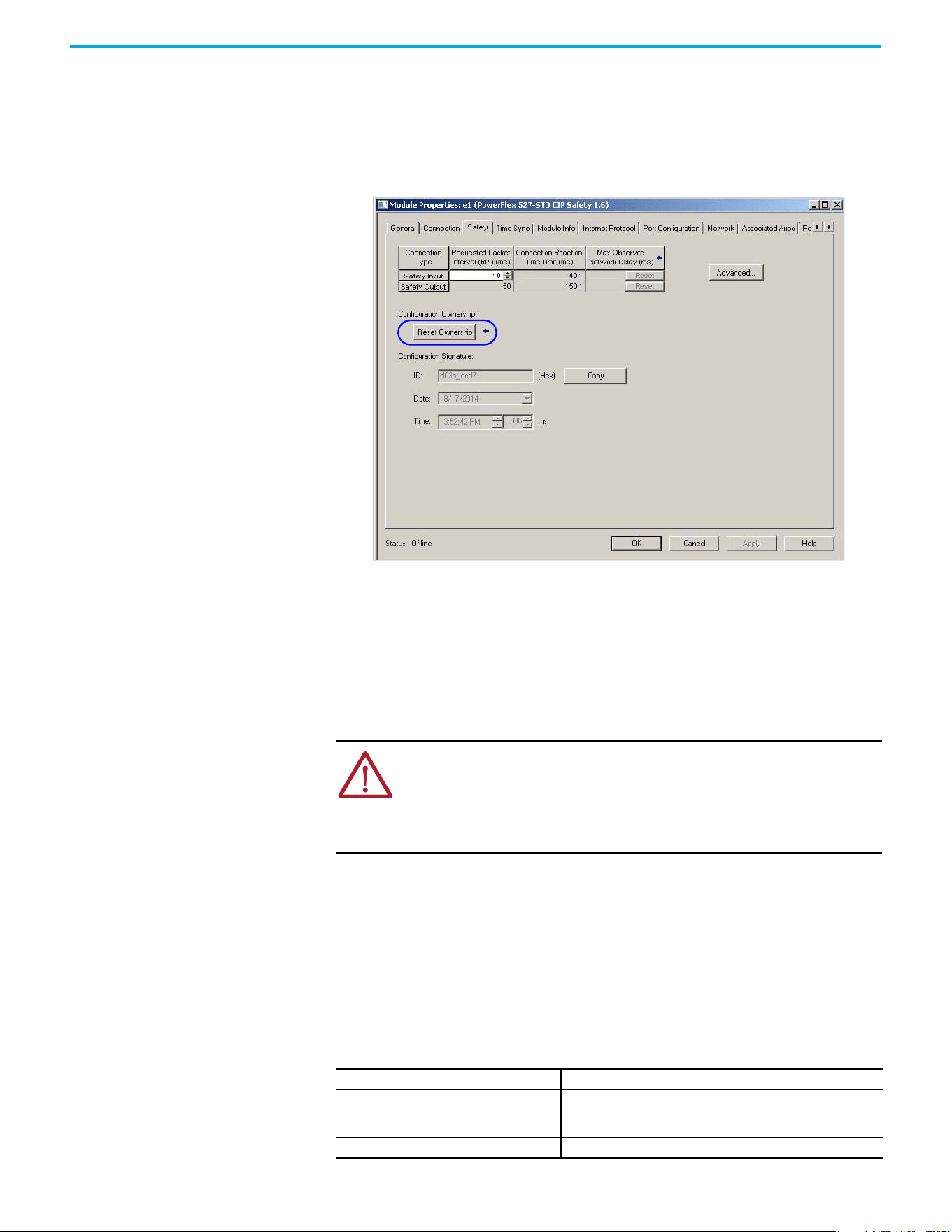
104 Rockwell Automation Publication 520-UM002E-EN-E - September 2024
Chapter 6 Network Control of Safe Torque Off
Scenario 3 – Replacement Integrated Safety Drive SNN is Different from Original and no
Safety Signature Exists
1. Remove and replace the existing integrated safety drive.
2. Right-click the replacement drive and choose Properties.
3. Select the Safety tab.
4. Select Reset Ownership.
5. Select OK.
6. Power cycle the drive.
7. Follow your company-prescribed procedures to functionally test the replacement drive and
system and to authorize the system for use.
Replacement with “Configure Always” Enabled
When the Configure Always feature is enabled, the controller automatically checks for and
connects to a replacement drive that meets all the following requirements:
• The controller has configuration data for a compatible drive at that network address.
• The drive is in the Out-of-box condition or has an SNN that matches the configuration.
If the project is configured for Configure Always, follow the appropriate steps to replace a
PowerFlex 527 drive.
Follow these steps when the Configure Always feature is enabled.
1. Remove and replace the existing integrated safety drive.
ATTENTION: Enable the Configure Always feature only if the entire integrated
safety control system is not being relied on to maintain SIL 3 behavior during the
replacement and functional testing of a PowerFlex 527 drive. Do not place drives
that are in the Out-of-box condition on an integrated safety network when the
Configure Always feature is enabled, except while following this replacement
procedure.
If Then
The drive is in the Out-of-box condition
Go to step 6.
No action is needed for the GuardLogix controller to take ownership of
the drive.
An SNN mismatch error occurs Go to the next step to reset the drive to the Out-of-box condition.
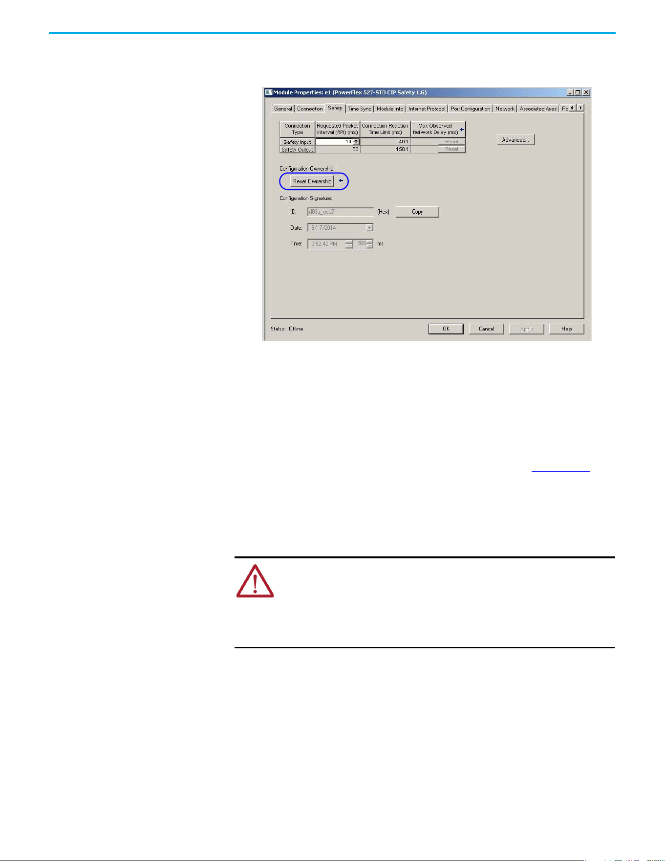
Rockwell Automation Publication 520-UM002E-EN-E - September 2024 105
Chapter 6 Network Control of Safe Torque Off
2. Right-click the replacement drive and choose Properties.
3. Select the Safety tab.
4. Select Reset Ownership.
5. Select OK.
6. Follow your company-prescribed procedures to functionally test the replacement drive and
system and to authorize the system for use.
Motion Direct Commands in
Motion Control Systems
You can use the Motion Direct Command (MDC) feature to initiate motion while the controller is in
Program mode, independent of application code that is executed in Run mode. These commands
let you perform a variety of functions, for example, move an axis, jog an axis, or home an axis. See
the Logix 5000 Controllers Motion Instructions Reference Manual, publication MOTION-RM002
for
more information.
A typical use might involve a machine integrator testing different parts of the motion system while
the machine is being commissioned, or a maintenance engineer, under certain restricted scenarios
in accordance with safe machine operating procedures, wanting to move an axis (like a conveyor)
to clear a jam before resuming normal operation.
Understanding STO Bypass When Using Motion Direct Commands
If a Safety-only connection between the GuardLogix safety controller and the PowerFlex 527 drive
was established at least once after the drive was received from the factory, the drive does not
allow motion while the safety controller is in Program mode by default.
This is because the safety task is not executed while the GuardLogix safety controller is in Program
mode. This applies to applications running in a single safety controller (with Motion and Safety
connections). When an integrated safety drive has a Motion connection to a standard controller and
a separate Safety connection to a dual-safety controller, the standard controller can transition to
Program mode while the safety controller stays in Run mode and continues to execute the safety
task.
ATTENTION: To avoid personal injury or damage to equipment, follow these
rules regarding Run mode and Program mode.
• Only authorized, trained personnel with knowledge of safe machine operation
should be allowed to use Motion Direct Commands.
• Additional supervisory methods, like removing the controller keyswitch, should
be used to maintain the safety integrity of the system after returning the safety
controller to RUN mode.
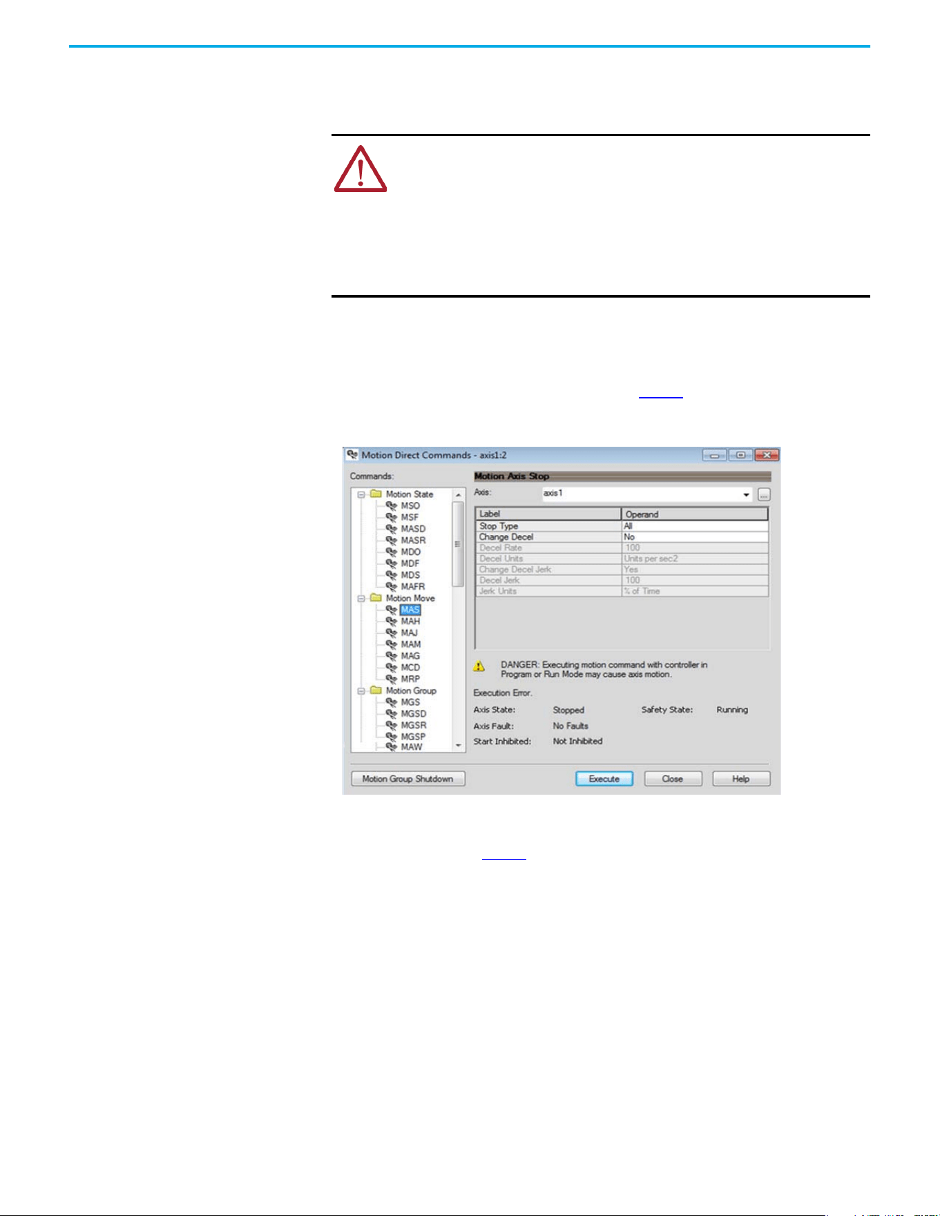
106 Rockwell Automation Publication 520-UM002E-EN-E - September 2024
Chapter 6 Network Control of Safe Torque Off
However, PowerFlex 527 drive systems are designed with a bypass feature for the STO function in
single-safety controller configurations. You can use the MDC feature to allow motion while following
all necessary and prescribed steps per your machine's safety operating procedures.
Logix Designer Application Warning Messages
When the controller is in Run mode, executing safety functions, the PowerFlex 527 drive follows the
commands that it receives from the safety controller. The controller will report Safety state =
Running and Axis state = Stopped/Running, as shown in Figure 4.
Figure 4 - Safety State Indications When Controller is in Run Mode (Safety Task Executing)
When the controller transitions to Program mode, the integrated safety drive is in the safe state
and torque is not permitted. The controller will report Safety state = Not Running and Axis state =
Start Inhibited, as shown in Figure 5.
ATTENTION: Consider the consequences of allowing motion through the use of
MDC when the controller is in Program mode. You must acknowledge warning
messages in the Logix Designer application that warn of the drive bypassing the
STO function and unintended motion can occur. The integrated safety drive
does not respond to requests of the STO function if MDC mode is entered.
ATTENTION: It is your responsibility to maintain machine safety integrity while
executing motion direct commands. One alternative is to provide ladder logic
for Machine Maintenance mode that leaves the controller in Run mode with
safety functions executing.
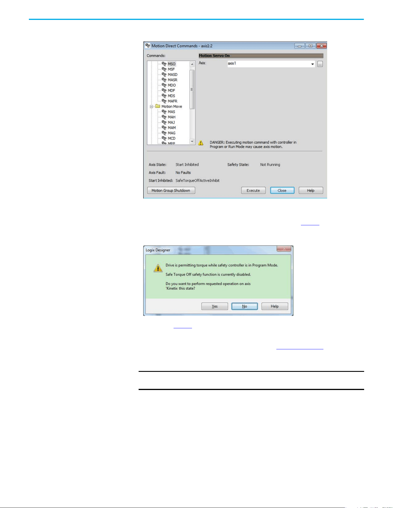
Rockwell Automation Publication 520-UM002E-EN-E - September 2024 107
Chapter 6 Network Control of Safe Torque Off
Figure 5 - Safety State Indications After Controller Transitions to Program Mode
When you issue a motion direct command to an axis to produce torque in Program mode, for
example MSO or MDS, with the safety connection present to the drive, a warning message is
presented before the motion direct command is executed, as shown in Figure 6
.
Figure 6 - STO Bypass Prompt When the Safety Controller is in Program Mode
The warning in Figure 6 is displayed the first time a motion direct command is issued.
After you acknowledge the warning message by selecting Yes, torque is permitted by the drive and
a warning message is indicated in the software as shown in Figure 7 on page 108
. The controller
will report Safety state = Not Running (Torque Permitted), Axis state = Stopped/Running, and
Persistent Warning = Safe Torque Off Bypassed.
IMPORTANT Switch the controller to Run mode to exit Motion Direct Command mode and
end the bypass of the STO function.
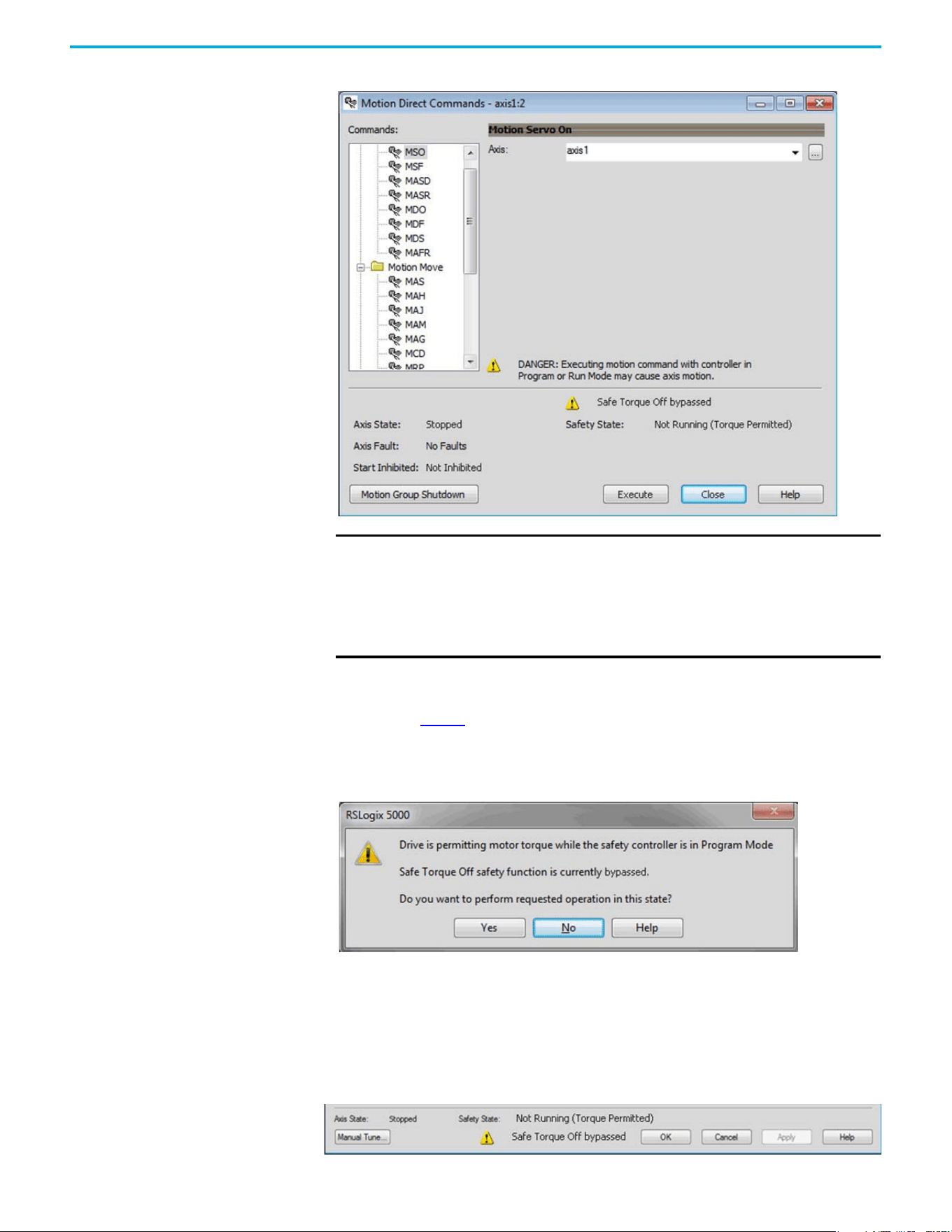
108 Rockwell Automation Publication 520-UM002E-EN-E - September 2024
Chapter 6 Network Control of Safe Torque Off
Figure 7 - Safety State Indications After Controller Transitions to Program Mode (MDC Executing)
Torque Permitted in a Multi-workstation Environment
The warning in Figure 8 is displayed to notify a second user working in a multi-workstation
environment that the first user has placed the integrated safety drive in the STO state and that the
current action is about to bypass the STO state and permit torque.
Figure 8 - STO Bypass Prompt When MDC is Issued in Multi-workstation Environment
Warning Icon and Text in Axis Properties
In addition to the other warnings that require your acknowledgment, the Logix Designer application
also provides warning icons and persistent warning messages in other Axis Properties dialog boxes
when the integrated safety drive is in STO Bypass mode.
Axis and Safe State Indications on the Hookup Services Dialog Box
IMPORTANT The persistent warning message text Safe Torque Off bypassed appears
when a motion direct command is executed.
The warning message persists - even after the dialog is closed and
reopened - as long as the integrated safety drive is in STO Bypass mode.
The persistent warning message is removed only after the integrated safety
drive is restored to the Safe state.
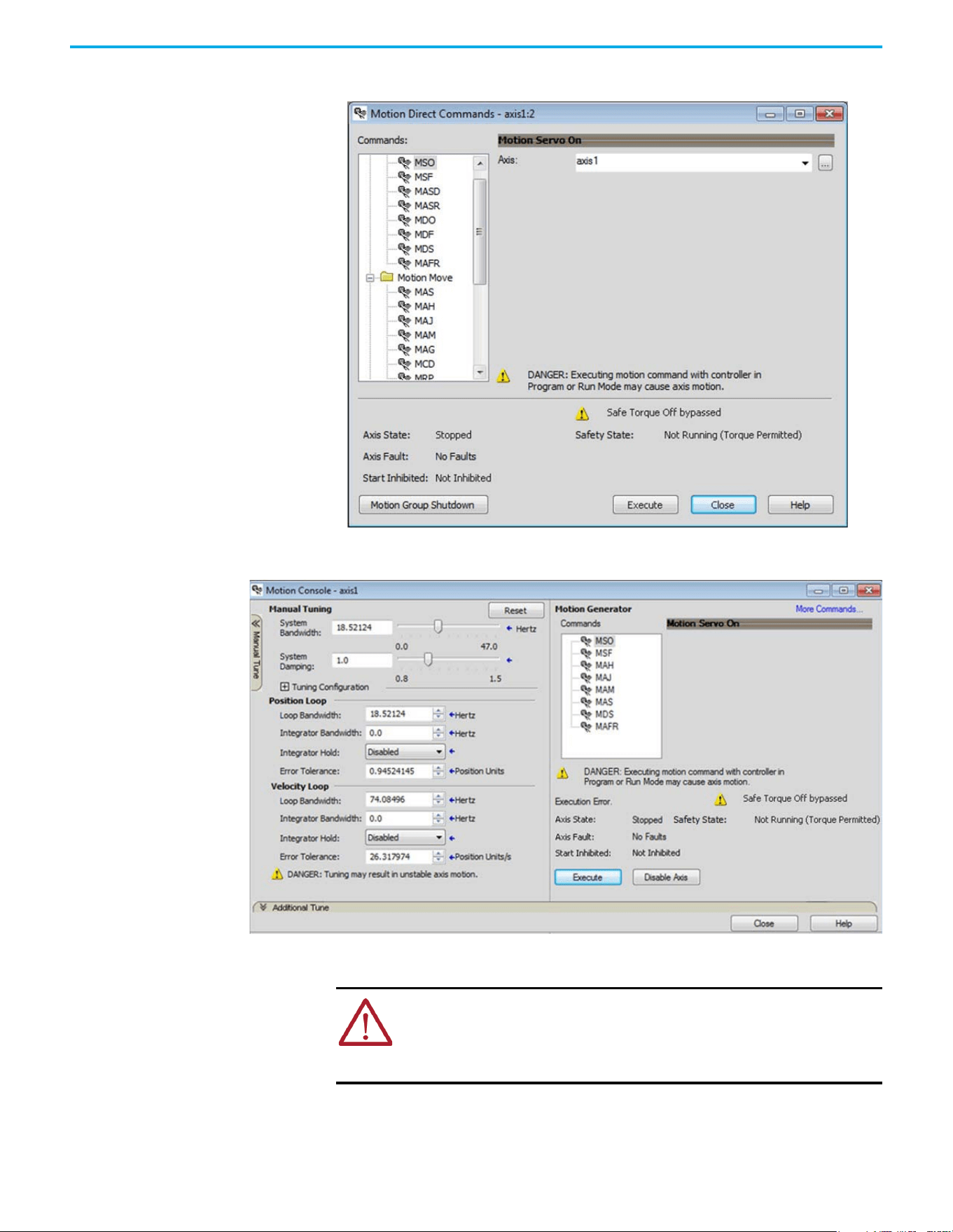
Rockwell Automation Publication 520-UM002E-EN-E - September 2024 109
Chapter 6 Network Control of Safe Torque Off
Axis and Safe State Indications on Motion Direct Commands Dialog Box
Axis and Safe State Indications on the Motion Console Dialog Box
Functional Safety
Considerations
ATTENTION: Before maintenance work can be performed in Program mode, the
developer of the application must consider the implications of allowing motion
through motion direct commands and should consider developing logic for
runtime maintenance operations to meet the requirements of machine safety
operating procedures.

110 Rockwell Automation Publication 520-UM002E-EN-E - September 2024
Chapter 6 Network Control of Safe Torque Off
ATTENTION: Motion is allowed and the STO function is not available when
motion direct commands are used in Program mode.
Motion direct commands that are issued when the controller is in Program
mode cause the drive to bypass the STO Active condition.
It is your responsibility to implement additional preventive measures to
maintain safety integrity of the machinery during execution of motion direct
commands in Program mode.
ATTENTION: To avoid personal injury and damage to equipment in the event of
unauthorized access or unexpected motion during authorized access, return the
controller to Run mode and remove the key before leaving the machine
unattended.
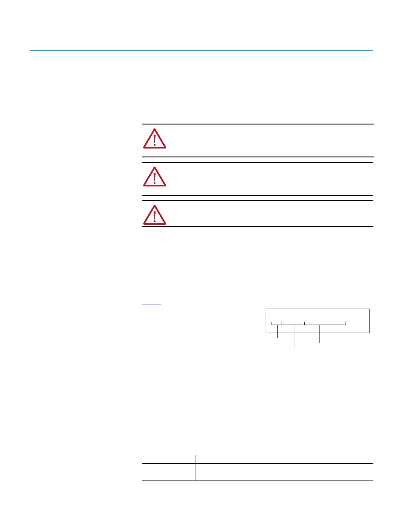
Rockwell Automation Publication 520-UM002E-EN-E - September 2024 111
Chapter 7
Chapter
Troubleshooting
This chapter provides troubleshooting tables and related information for your PowerFlex 527 drive.
Safety Precautions Observe the following safety precautions when troubleshooting your PowerFlex 527 drive.
Interpret Status Indicators See these troubleshooting tables to identify faults, potential causes, and the appropriate actions to
resolve the fault. If the fault persists after attempting to troubleshoot the system, contact your
Rockwell Automation sales representative for further assistance.
Display Interface
The LCD display provides fault messages and troubleshooting information by using the soft menu
items and navigation buttons. See Understanding the PowerFlex 527 Display and Indicators on
page 44 for more information.
Fault Codes
The fault code tables are designed to help you determine the source of the fault or exception. When
a fault condition is detected, the drive performs the appropriate fault action, the fault is displayed,
and the fault is added to a persistent fault log (along with diagnostics data). The earlier faults have
priority to be displayed.
The drive removes the fault text from the display when a Fault Reset service is sent from the
controller and the fault is no longer active. If a fault is still active following a Fault Reset service, the
fault is again posted to the display and written to the fault log.
ATTENTION: Capacitors on the DC bus can retain hazardous voltages after input
power has been removed. Before working on the drive, measure the DC bus
voltage to verify it has reached less than 50V DC, or wait three minutes. Failure
to observe this precaution could result in severe bodily injury or loss of life.
ATTENTION: Do not attempt to defeat or override the drive fault circuits. You
must determine the cause of a fault and correct it before you attempt to
operate the system. Failure to correct the fault could result in personal injury
and/or damage to equipment as a result of uncontrolled machine operation.
ATTENTION: Provide an earth ground for test equipment (oscilloscope) used in
troubleshooting. Failure to ground the test equipment could result in personal
injury.
Fault Code Summary
Fault Code Type Description
FLT Sxx
Standard runtime axis exceptions.
FLT Mxx
INIT FLT S03 NVMEM CHKSUM
Fault type
Fault code
Fault description
When the drive enters a fault or inhibit scenario,
the fault information will be shown and scrolled
across the LCD display.
112 Rockwell Automation Publication 520-UM002E-EN-E - September 2024
Chapter 7 Troubleshooting
See Troubleshoot the Safe Torque Off Function on page 90 for information on troubleshooting
SAFE FLT fault codes.
INIT FLT Sxx
Exceptions that prevent normal operation and occur during the initialization process.
INIT FLT Mxx
INHIBIT Sxx
Exceptions that prevent normal operation and indicate whenever the drive is active.
INHIBIT Mxx
NODE FLTxx Exceptions that prevent normal operation of the drive.
NODE ALARM xx
Exceptions that prevent normal operation of the drive, but do not result in any action other
than reporting the alarm to the controller.
Fault codes triggered by conditions that fall outside factory set limits are
identified by FL at the end of the display message. For example,
FLT S07 – MTR OVERLOAD FL.
Fault codes triggered by conditions that fall outside user set limits are
identified by UL at the end of the display message. For example,
FLT S08 – MTR OVERLOAD UL.
Fault Code Summary (Continued)
Fault Code Type Description
FLT Sxx Fault Codes
Exception Code on Display Exception Text Problem Possible Solutions
FLT S03 – MTR OVERSPEED FL Motor Overspeed Factory Limit Fault Motor speed has exceeded 590 Hz. Check control loop tuning.
FLT S04 – MTR OVERSPEED UL Motor Overspeed User Limit Fault
Motor speed has exceeded the user-defined
speed limit that is given by Motor Overspeed
User Limit.
Check control loop tuning.
FLT S07 – MTR OVERLOAD FL
Motor Thermal Overload Factory Limit
Fault
The motor thermal model has exceeded its
factory set thermal capacity limit of 110%.
Modify the command profile to reduce speed
or increase time.
FLT S08 – MTR OVERLOAD UL Motor Thermal Overload User Limit Fault
The motor thermal model has exceeded the
thermal capacity limit that is given by Motor
Thermal Overload User Limit.
• Modify the command profile.
• Increase the Motor Thermal Overload UL
attribute value.
FLT S10 – INV OVERCURRENT Inverter Overcurrent Fault
Inverter current has exceeded the
instantaneous current limit (determined by
hardware).
• Check motor power cable for shorts.
• Verify that motor windings are not
shorted.
• Verify motor power wire gauge.
• Operate within the continuous power
rating.
• Reduce acceleration times.
FLT S11 – INV OVERTEMP FL
Inverter Overtemperature Factory Limit
Fault
The measured inverter temperature has
exceeded the factory set temperature limit.
• Modify the command profile to reduce
speed or increase time.
• Reduce drive ambient temperature.
• Verify that airflow through drive is not
obstructed.
FLT S13 – INV OVERLOAD FL
Inverter Thermal Overload Factory Limit
Fault
The thermal model for the power transistors
indicates that the temperature has exceeded
the factory set thermal capacity rating of
110%.
Modify the command profile to reduce speed
or increase time.
FLT S16 – GROUND CURRENT Ground Current Factory Limit Fault
The sensing circuitry in the power stage has
detected excessive ground current.
• Check motor power wiring; check power
cable for shorts.
• Replace motor if the fault persists.
FLT S23 – AC PHASE LOSS AC Single Phase Loss Fault
A single AC input phase was lost while the
drive was enabled.
Check AC input voltage on all phases.
FLT S25 – PRECHARGE FAILURE Pre-charge Failure Fault
The pre-charge circuit monitoring algorithm
detected that the DC bus did not reach a
factory set voltage level after charging for a
period of time.
• Check AC input voltage on all phases.
• Check input power wiring.
• Replace drive if fault persists.
FLT S29 – BUS OVERLOAD FL
Bus Regulator Thermal Overload Factory
Limit Fault
The shunt thermal model has exceeded its
factory set thermal capacity limit.
• Modify the duty cycle of the application.
• Add external shunt for additional capacity.
• Add capacitor module if needed.

Rockwell Automation Publication 520-UM002E-EN-E - September 2024 113
Chapter 7 Troubleshooting
FLT S34 – BUS UNDERVOLT UL Bus Undervoltage User Limit Fault
DC Bus voltage level is below the user set
limit as given by Bus Undervoltage User
Limit.
• Verify voltage level of the incoming AC.
• Monitor AC power source for glitches or
line droop.
• Install UPS on AC input.
• Decrease Bus Undervoltage UL attribute
value.
FLT S35 – BUS OVERVOLT FL Bus Overvoltage Factory Limit Fault
DC Bus voltage level is above the factory set
limit as determined by the configured input
voltage.
• Change the deceleration or motion profile
of all drives that are connected to the DC
bus.
• Unplug the shunt connector and measure
the resistance of the shunt.
• Replace drive if shunt resistor is open.
FLT S37 – BUS POWER LOSS Bus Power Loss
DC Bus voltage level is below the Bus Power
Loss Threshold for more than the timeout
period specified Bus Power Loss Time value.
• Verify voltage level of the incoming AC.
• Monitor AC power source for glitches or
line droop.
• Install UPS on AC input.
FLT S41 – FDBK SIGNAL NOISE FL Feedback Signal Noise Fault
Noise induced A/B channel state changes
(illegal states) from a feedback device were
detected by the drive. Specifically, the
number of these noise events that have
occurred on this channel has exceeded the
Feedback Noise Factory Limit. The offending
feedback channel number is encoded in the
associated Fault/Alarm Sub Code.
• Check motor feedback cable and
connector.
• Cycle power.
• Check feedback shield connection.
• Reduce shock and vibration to motor.
• Replace motor if fault continues.
• Verify all HTL/TTL DIP switches on the
25-ENC-2/B encoder are set in the same
position.
FLT S43 – FDBK SIG FL Feedback Signal Loss Factory Limit Fault
The absolute value of the differential A/B
signals is below a factory limit.
• Check motor feedback cable and
connector.
• Check that motor power cable and
feedback wire shields are secured
correctly.
• Check that motor frame is grounded
correctly.
FLT S50 – HARDWARE OVERTRAVEL
POSITIVE
Hardware Overtravel Positive
Axis moved beyond the physical travel limits
in the positive direction and activated the
Positive Overtravel limit switch.
• Check wiring.
• Verify motion profile.
• Verify axis configuration in software.
FLT S51 – HARDWARE OVERTRAVEL
NEGATIVE
Hardware Overtravel Negative
Axis moved beyond the physical travel limits
in the negative direction and activated the
Negative Overtravel limit switch.
• Check wiring.
• Verify motion profile.
• Verify axis configuration in software.
FLT S54 – POSN ERROR Excessive Position Error Fault
The position error of the position control loop
has exceeded the value that is given by
Position Error Tolerance for a time period
that is given by Position Error Tolerance
Time.
• Check position loop tuning.
• Increase the feedforward gain.
•Verify sizing of the drive and motor.
• Check motor power wiring.
• Increase Position Error Tolerance and/or
Position Error Tolerance Time attribute
values.
FLT S55 – VEL ERROR Excessive Velocity Error Fault
The velocity error of the velocity control loop
has exceeded the value that is given by
Velocity Error Tolerance for a time period
that is given by Velocity Error Tolerance
Time.
• Check velocity loop tuning.
• Reduce acceleration.
•Verify sizing of the drive and motor.
• Check motor power wiring.
• Increase Velocity Error Tolerance and/or
Velocity Error Tolerance Time attribute
values.
FLT S56 – OVERTORQUE LIMIT Overtorque Limit Fault
Motor torque has risen above user-defined
maximum torque level that is given by
Overtorque Limit for a time period that is
given by Overtorque Limit Time.
• Verify Torque Trim value.
• Verify motion profile.
•Verify sizing of the drive and motor.
• Increase Overtorque Limit and/or
Overtorque Limit Time attribute values.
FLT S57 – UNDERTORQUE LIMIT Undertorque Limit Fault
Motor torque has dropped below user-
defined minimum torque level that is given
by Undertorque Limit for a time period that is
given by Undertorque Limit Time.
• Verify motion profile.
•Verify sizing of the drive and motor.
• Decrease Undertorque Limit and/or
Undertorque Limit Time attribute values.
FLT S61 – ENABLE INPUT DEACTIVATED Enable Input Deactivated
Enable Input has been deactivated while the
axis power structure is in Running state,
enabled, and supplying current to the DC Bus
or motor.
• Verify Enable Input level.
• Check Enable Input wiring.
FLT Sxx Fault Codes (Continued)
Exception Code on Display Exception Text Problem Possible Solutions

114 Rockwell Automation Publication 520-UM002E-EN-E - September 2024
Chapter 7 Troubleshooting
FLT Mxx Fault Codes
Exception Code on Display Exception Text Problem Possible Solutions
FLT M10 – CONTROL MODULE
OVERTEMPERATURE FL
Control Module Overtemperature Fault
The temperature sensor on the Main Control
Board detected excessive heat.
• Reduce drive ambient temperature.
• Verify that airflow through drive is not
obstructed.
• Check control module internal fan.
Replace if error persists.
FLT M19 – DECEL OVERRIDE Decel Override
The drive is not following a commanded
deceleration because it is attempting to limit
bus voltage.
• Reprogram Bus Regulator Action to
eliminate any “Adjustable Freq” selection.
• Reprogram Bus Regulator Action to Shunt
Regulator and add external shunt.
• Correct AC input line instability or add an
isolation transformer.
• Reset drive.
FLT M21 – MOTOR TEST FAILURE Motor Test Failure The Motor Test procedure has failed.
• Verify sizing of the drive and motor.
• Verify motor data.
• Check motor power wiring.
FLT M26 – RUNTIME ERROR Runtime Error
The drive firmware encountered an
unrecoverable runtime error.
• Cycle power.
• Reset the drive.
• Return drive for repair if fault continues.
FLT M28 – SAFETY MODULE COM ERROR Safety Module Communication Error Error in communicating to the Safety module.
• Cycle power.
• Replace module.
INIT FLT Fault Codes
Exception Code on Display Exception Text Problem Possible Solutions
INIT FLT S03 – NVMEM CHKSUM Nonvolatile Memory Checksum Error
Data in the nonvolatile memory has a
checksum error.
• Cycle power.
• Reset the drive.
• Return drive for repair if fault continues.
INIT FLT M14 – INVALID SAFETY FIRMWARE Invalid Safety Firmware
The safety firmware is not compatible with
the drive firmware, or the main safety
firmware is missing.
• Cycle power.
• Upgrade drive firmware.
• Return drive for repair if fault continues.
INIT FLT M15 – POWER BOARD Power Board Checksum Error The power board has a checksum error.
• Cycle power.
• Reset the drive.
• Return drive for repair if fault continues.
INIT FLT M22 – ILLEGAL ADDRESS Illegal IP Address Configuration
Invalid Ethernet IP Address configuration or
device Node Address is out of range (>254)
For example, this fault will occur when the IP
address and Gateway address are identical.
When this fault occurs, IP address
configuration will be changed to DHCP.
Change IP address, subnet mask, and
gateway address to a legal configuration and
cycle power.
INHIBIT Fault Codes
Exception Code on Display Exception Text Problem Possible Solutions
INHIBIT S01 – AXIS ENABLE INPUT Axis Enable Input Axis Enable Input is not active.
• Verify Enable Input level.
• Check Enable Input wiring.
INHIBIT S02 – MOTOR NOT CONFIGURED Motor Not Configured
The motor has not been properly configured
for use.
Verify motor configuration in the Studio 5000
Logix Designer application.
INHIBIT S05 – SAFE TORQUE OFF
(1)
Start Inhibit – Safe Torque Off
The safety function has disabled the power
structure.
• Check that Ethernet components such as
cables are secured and switches are
operational.
• Check state of safety devices.
INHIBIT M05 – SAFE TORQUE OFF
(2)
Start Inhibit – Safe Torque Off
The safety function has disabled the power
structure.
• Check safety input wiring.
• Check state of safety devices.
(1) Network STO.
(2) Hardwired STO.

Rockwell Automation Publication 520-UM002E-EN-E - September 2024 115
Chapter 7 Troubleshooting
NODE FLT Fault Codes
Exception Code on Display Exception Text Problem Possible Solutions
NODE FLT 01 – LATE CTRL UPDATE Control Connection Update Fault
Several consecutive updates from the
controller have been lost.
• Remove unnecessary network devices
from the motion network.
• Change network topology so that fewer
devices share common paths.
•Use high-performance network
equipment.
• Use shielded cables.
• Separate signal wiring from power wiring.
NODE FLT 02 – PROC WATCHDOG nn Processor Watchdog Fault
The processor on the power board or control
board failed to update in a certain amount of
time.
The nn sub-codes 00…05 are internal and
result in the same possible solution.
• Cycle power.
• Update the drive firmware.
• Return drive for repair if fault continues.
NODE FLT 03 – HARDWARE 00 Hardware Fault - PwrIF
Communication with the power board could
not be established.
• Cycle power.
• Update the drive firmware.
• Return drive for repair if fault continues.
NODE FLT 03 – HARDWARE 01 Hardware Fault - Piccolo HW DSP chip on the power board failure.
• Cycle power.
• Return motor for repair if fault continues.
NODE FLT 05 – CLOCK SKEW FLT Clock Skew Fault
The controller time and the drive system
time are not the same.
• Cycle power.
• Check controller and Ethernet switch
operation.
NODE FLT 06 – LOST CTRL CONN Lost Controller Connection Fault
Communication with the controller has been
lost.
• Check Ethernet connection.
• Check controller and Ethernet switch
operation.
NODE FLT 07 – CLOCK SYNC Clock Sync Fault
Drive local clock has lost synchronization
with controller's clock and was not able to
resynchronize within allotted time.
• Check Ethernet connection.
• Check controller and Ethernet switch
operation.
NODE FLT 09 – DUPLICATE IP ADDRESS Duplicate IP Address Fault
Several consecutive updates from the
controller have been lost.
Select an IP address not already in use on
the network.
NODE ALARM Fault Codes
Exception Code on Display Exception Text Problem Possible Solutions
NODE ALARM 01 – LATE CTRL UPDATE Control Connection Update Alarm Updates from the controller have been late.
• Remove unnecessary network devices
from the motion network.
• Change network topology so that fewer
devices share common paths.
•Use high-performance network
equipment.
• Use shielded cables.
• Separate signal wiring from power wiring.
NODE ALARM 03 – CLOCK JITTER Clock Jitter Alarm
The sync variance has exceeded the sync
threshold while the device is running in sync
mode.
• Check the Ethernet connection.
• Check controller and Ethernet switch
operation.
NODE ALARM 04 – CLOCK SKEW ALARM Clock Skew Alarm
The controller time and the drive system
time are not the same.
• Check the Ethernet connection.
• Check controller and Ethernet switch
operation.
NODE ALARM 05 – CLOCK SYNC ALARM Clock Sync Alarm
Drive local clock has lost synchronization
with controller's clock for a short time during
synchronous operation.
• Check the Ethernet connection.
• Check controller and Ethernet switch
operation.
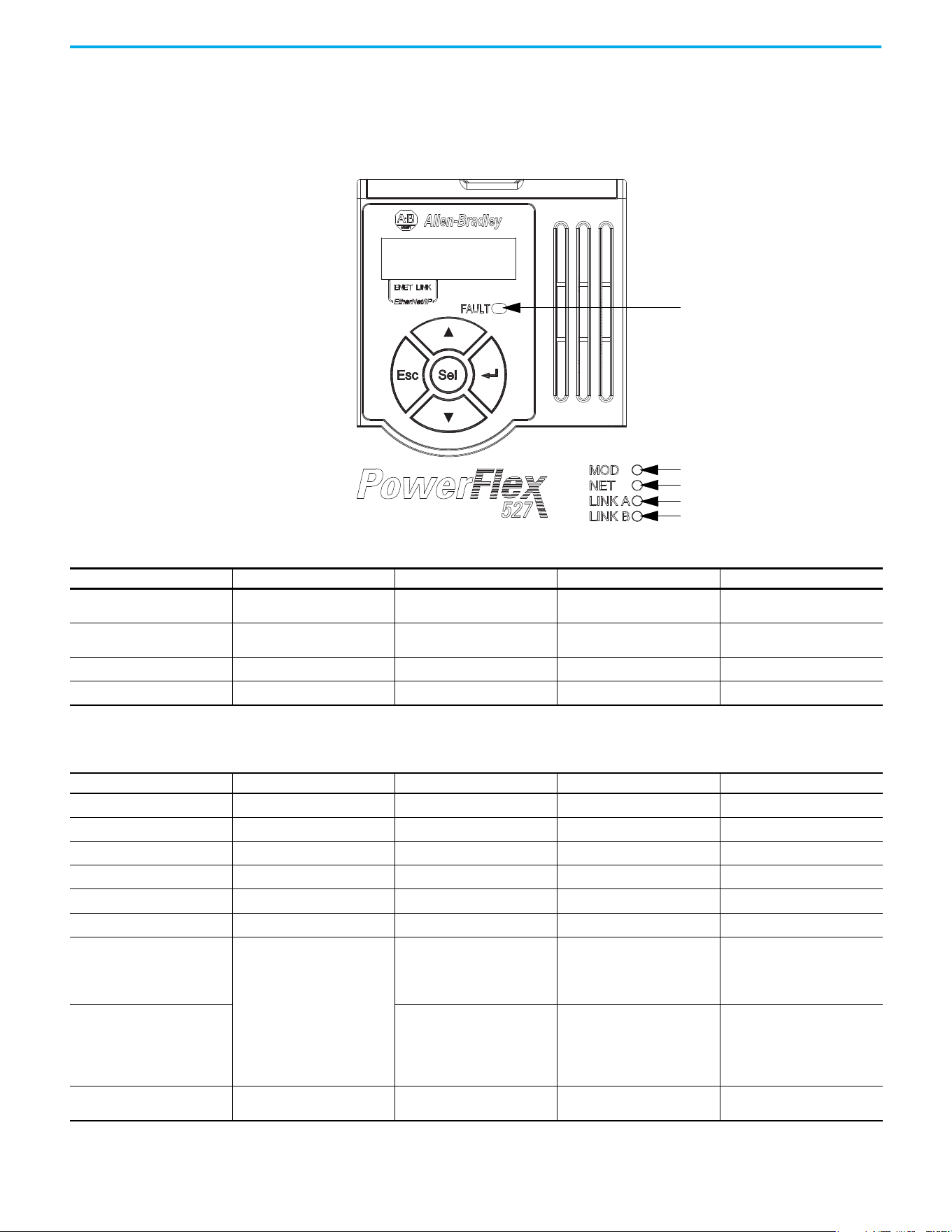
116 Rockwell Automation Publication 520-UM002E-EN-E - September 2024
Chapter 7 Troubleshooting
PowerFlex 527 Drive Status Indicators
The fault status indicator is located between the LCD display and keypad. There are also four
status indicators that are located at the bottom right of the drive and can be seen through the front
cover of the control module.
Module status
Network status
Link A status (Ethernet port 1)
Link B status (Ethernet port 2)
Fault status
Fault Status Indicator
Condition Safety Supervisor State CIP Motion Axis State Governing Object Identity State
Steady Red
Any State
(1)
Aborting Motion Axis
Major Recoverable or
Major Unrecoverable
Steady Red
Any State
(1)
Major Faulted Motion Axis
Major Recoverable or
Major Unrecoverable
Steady Red Abort
Any State
(1)
Safety Supervisor Major Recoverable
Steady Red Critical Fault
Any State
(1)
Safety Supervisor Major Unrecoverable
(1) “Any State” means any state that has lower precedence.
Module Status Indicator
Condition Safety Supervisor State CIP Motion Axis State Governing Object Identity State
Flashing Green/Red Self-Testing
Any State
(1)
Safety Supervisor Device Self-Testing
Flashing Green/Red
Any State
(1)
Self-Testing Motion Axis Device Self-Testing
Steady Red Self-Test Exception
Any State
(1)
Safety Supervisor Major Unrecoverable
Flashing Green/Red
Waiting for TUNID
(2)
Any State
(1)
Safety Supervisor Standby
Flashing Green/Red Configuring
Any State
(1)
Safety Supervisor Standby
Flashing Green Idle
Any State
(1)
Safety Supervisor Standby
Flashing Green
• Waiting for TUNID with Torque
Permitted
(2)(3)
•Executing
• Executing with Torque
Permitted
(4)
• Initializing
•Pre-Charge
•Shutdown
• Start Inhibit
Motion Axis Standby
Steady Green
• Stopped
• Stopping
•Starting
• Running
•Testing
Motion Axis Operational
Flashing Red or Steady Red
Any State
(1)
Aborting Motion Axis
Major Recoverable or
Major Unrecoverable
Rockwell Automation Publication 520-UM002E-EN-E - September 2024 117
Chapter 7 Troubleshooting
General Troubleshooting These conditions do not always result in a fault code, but can require troubleshooting to improve
performance.
Flashing Red
Any State
(1)
Major Faulted Motion Axis
Major Recoverable or
Major Unrecoverable
Flashing Red Abort
Any State
(1)
Safety Supervisor Major Recoverable
Steady Red Critical Fault
Any State
(1)
Safety Supervisor Major Unrecoverable
(1) “Any State” means any state that has lower precedence.
(2) After Propose_TUNID service request, the Network Status indicator flashes Green/Red (fast flash) until successful Apply_TUNID.
(3) Unlike many safety I/O devices, a CIP Motion safety drive is free to operate in its “Out-of-Box” state. This behavior is made explicit by the device specific Safety Supervisor state, Waiting for TUNID with
Torque Permitted. In this “Out-of-Box” state, operation of the CIP Motion safety drive is the same as that of a CIP Motion drive to facilitate commissioning.
(4) Unlike many safety I/O devices, a CIP Motion safety drive may be operated when the safety output assemblies Run/Idle bit is set to Idle. If in the Executing state, the Run/Idle bit is set to Idle, the
device is forced to a Safe State. However, if in this condition, the safety controller sends a Mode_Change service request with Torque Permitted to the Safety Stop Functions object, drive operation is
permitted while the Run/Idle bit remains Idle. See the Safety Stop Function object for details on the Mode_Change service.
Module Status Indicator (Continued)
Condition Safety Supervisor State CIP Motion Axis State Governing Object Identity State
Network Status Indicator
Condition Status
Off No power applied to the drive or IP address is not configured.
Flashing Green Drive connection is not established, but has obtained an IP address.
Steady Green Drive is online and has connections in the established state.
Flashing Red One or more Exclusive Owner connections has timed out.
Steady Red Duplicate IP address. IP address that is specified is already in use.
Flashing Green/Red (slow flash) The drive performs self-test during powerup.
Flashing Green/Red (fast flash) Safety Supervisor is waiting for “Apply TUNID” service request.
Link A Status Indicator (Ethernet Port 1)
Condition Status
Off Drive is not connected to the network.
Steady Green Drive is connected to the network but not transmitting data.
Flashing Green Drive is connected to the network and transmitting data.
Link A Status Indicator (Ethernet Port 2)
Condition Status
Off Drive is not connected to the network.
Steady Green Drive is connected to the network but not transmitting data.
Flashing Green Drive is connected to the network and transmitting data.
General Troubleshooting
Condition Potential Cause Possible Resolution
Axis or system is unstable.
The position feedback device is incorrect or open. Check wiring.
Motor tuning limits are set too high. Run Tune in the Logix Designer application.
Position loop gain or position controller accel/decel rate is improperly set. Run Tune in the Logix Designer application.
Improper grounding or shielding techniques are causing noise to be
transmitted into the position feedback or velocity command lines, causing
erratic axis movement.
Check wiring and ground.
Motor Data is incorrectly set (induction motor is not matched to axis
module).
•Check setups.
• Run Motor Test in the Logix Designer application.
Mechanical resonance.
Notch filter or output filter can be required (refer to Axis
Properties dialog box, Output tab in the Logix Designer
application).

118 Rockwell Automation Publication 520-UM002E-EN-E - September 2024
Chapter 7 Troubleshooting
You cannot obtain the motor
acceleration/deceleration that you
want.
Torque Limit limits are set too low. Verify that torque limits are set properly.
Incorrect motor selected in configuration.
Select the correct motor and run Tune in the Logix Designer
application again.
The system inertia is excessive.
• Check motor size versus application need.
• Review induction system sizing.
The system friction torque is excessive. Check motor size versus application need.
Available current is insufficient to supply the correct accel/decel rate.
• Check motor size versus application need.
• Review induction system sizing.
Acceleration limit is incorrect. Verify limit settings and correct them, as necessary.
Velocity Limit limits are incorrect. Verify limit settings and correct them, as necessary.
Motor does not respond to a
command.
The motor wiring is open. Check the wiring.
The motor cable shield connection is improper.
• Check feedback connections.
• Check cable shield connections.
The motor has malfunctioned. Repair or replace the motor.
The coupling between motor and machine has broken (for example, the
motor moves, but the load/machine does not).
Check and correct the mechanics.
Primary operation mode is set incorrectly. Check and properly set the limit.
Velocity or torque limits are set incorrectly. Check and properly set the limits.
Brake connector not wired Check brake wiring.
Presence of noise on command or
motor feedback signal wires.
Recommended grounding per installation instructions have not been
followed.
• Verify grounding.
• Route wire away from noise sources.
• See the System Design for Control of Electrical Noise
Reference Manual, publication GMC-RM001
.
Line frequency can be present.
• Verify grounding.
• Route wire away from noise sources.
Variable frequency can be velocity feedback ripple or a disturbance that is
caused by gear teeth or ballscrew, and so forth. The frequency can be a
multiple of the motor power transmission components or ballscrew speeds
resulting in velocity disturbance.
• Decouple the motor for verification.
• Check and improve mechanical performance, for example,
the gearbox or ballscrew mechanism.
No rotation
The motor connections are loose or open. Check motor wiring and connections.
Foreign matter is lodged in the motor. Remove foreign matter.
The motor load is excessive. Verify the induction system sizing.
The bearings are worn. Return the motor for repair.
The motor brake is engaged (if supplied).
• Check brake wiring and function.
• Return the motor for repair.
The motor is not connected to the load. Check coupling.
Motor overheating
The duty cycle is excessive.
Change the command profile to reduce accel/decel or increase
time.
The rotor is partially demagnetized causing excessive motor current. Return the motor for repair.
Abnormal noise
Motor tuning limits are set too high. Run Tune in the Logix Designer application.
Loose parts are present in the motor.
• Remove the loose parts.
• Return motor for repair.
• Replace motor.
Through bolts or coupling is loose. Tighten bolts.
The bearings are worn. Return motor for repair.
Mechanical resonance.
Notch filter can be required (See the Axis Properties dialog box,
Output tab in the Logix Designer application).
Erratic operation - Motor locks into
position, runs without control or with
reduced torque.
Motor power phases U and V, U and W, or V and W reversed. Check and correct motor power wiring.
General Troubleshooting (Continued)
Condition Potential Cause Possible Resolution

Rockwell Automation Publication 520-UM002E-EN-E - September 2024 119
Chapter 7 Troubleshooting
Logix 5000 Controller and
Drive Behavior
By using the Logix Designer application, you can configure how the PowerFlex 527 drives respond
when a drive fault/exception occurs.
The drive supports fault action for Ignore, Alarm, Minor Fault, and Major Fault as defined in Table 13
.
See the drive behavior tables beginning on page 120
for information on how the fault and stopping
actions apply to each of the exception fault codes.
The drive supports these configurable stopping actions
(1)
:
• Disable and Coast
• Current Decel and Disable
• Ramped Decel and Disable
(1) Disable and Coast and Current Decel and Disable are available in Frequency Control, Velocity Loop and Position Loop.
Ramped Decel and Disable is available in Frequency Control and Velocity Loop only and is not supported in Position Loop.
PowerFlex 527 Drive Exception Behavior
For PowerFlex 527 drives, you can configure exception behavior in the Logix Designer application
from the Axis Properties dialog box, Actions category.
Only selected drive exceptions are configurable. In the fault behavior tables, the controlling
attribute is given for programmable fault actions.
The INIT FLT xxx faults are always generated after powerup, but before the
drive is enabled, so the stopping behavior does not apply.
NODE ALARM xxx faults do not apply because they do not trigger stopping
behavior.
Table 13 - PowerFlex 527 Drive Exception Action Definitions
Exception Action Definition
Ignore
The controller completely ignores the exception condition. For some exceptions that
are fundamental to the operation of the planner, Ignore is not an available option.
Alarm
The controller sets the associated bit in the Motion Alarm Status word, but does not
otherwise affect axis behavior. Like Ignore, if the exception is so fundamental to the
drive, Alarm is not an available option. When an exception action is set to Alarm, the
Alarm goes away by itself when the exceptional condition has cleared.
Fault Status Only – Minor Fault
Like Alarm, Fault Status Only instructs the controller to set the associated bit in the
Motion Fault Status word, but does not otherwise affect axis behavior. However, unlike
Alarm an explicit Fault Reset is required to clear the fault once the exceptional
condition has cleared.
Like Ignore and Alarm, if the exception is so fundamental to the drive, Fault Status Only
is not an available option.
Stop Planner – Minor Fault
The controller sets the associated bit in the Motion Fault Status word and instructs the
Motion Planner to perform a controlled stop of all planned motion at the configured
maximum deceleration rate and holds at zero speed. An explicit Fault Reset is required
to clear the fault once the exceptional condition has cleared. If the exception is so
fundamental to the drive, Stop Planner is not an available option.
Stop Drive – Major Fault
When the exception occurs, the associated bit in the Fault Status word is set and the
axis comes to a stop by using the stopping action that is defined by the drive for the
particular exception that occurred. There is no controller based configuration to
specify what the stopping action is, the stopping action is device dependent.
Shutdown – Major Fault
When the exception occurs, the drive brings the motor to a stop by using the stopping
action defined by the drive (as in Stop Drive) and the power module is disabled. An
explicit Shutdown Reset is required to restore the drive to operation.
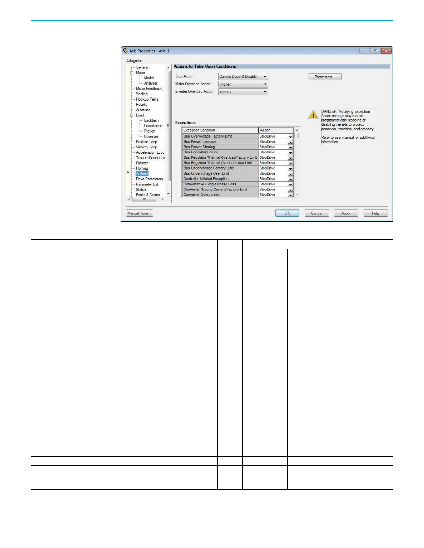
120 Rockwell Automation Publication 520-UM002E-EN-E - September 2024
Chapter 7 Troubleshooting
Logix Designer Axis Properties - Actions Category
Drive Behavior, FLT Sxx Fault Codes
Exception Fault Code Exception Text
Induction
Motor
Fault Action
Best Available Stopping
Action (applies to major
faults)
Ignore Alarm
Minor
Fault
Major
Fault
FLT S03 – MTR OVERSPEED FL Motor Overspeed Factory Limit Fault X X Disable and Coast
FLT S04 – MTR OVERSPEED ULMotor Overspeed User Limit Fault X XXXXDisable and Coast
FLT S07 – MTR OVERLOAD FL Motor Thermal Overload Factory Limit Fault X X Disable and Coast
FLT S08 – MTR OVERLOAD ULMotor Thermal OverLoad User Limit Fault X XXXXDisable and Coast
FLT S10 – INV OVERCURRENT Inverter Overcurrent Fault X X Disable and Coast
FLT S11 – INV OVERTEMP FL Inverter Overtemperature Factory Limit Fault X X Disable and Coast
FLT S13 – INV OVERLOAD FL Inverter Thermal Overload Factory Limit Fault X X Disable and Coast
FLT S16 – GROUND CURRENT Ground Current Factory Limit Fault X X Disable and Coast
FLT S23 – AC PHASE LOSS AC Single Phase Loss Fault X XXXXDisable and Coast
FLT S25 – PRECHARGE FAILURE Pre-charge Failure Fault X X Disable and Coast
FLT S29 – BUS OVERLOAD FL Bus Regulator Thermal OverLoad Factory Limit Fault X X Disable and Coast
FLT S34 – BUS UNDERVOLT ULBus Undervoltage User Limit Fault X XXXXDisable and Coast
FLT S35 – BUS OVERVOLT FL Bus Overvoltage Factory Limit Fault X X Disable and Coast
FLT S37 – BUS POWER LOSS Bus Power Loss X XXXXDisable and Coast
FLT S41 – FDBK SIGNAL NOISE FLFeedback Signal Noise Fault X XXXXDisable and Coast
FLT S43 – FDBK SIG FL Feedback Signal Loss Factory Limit Fault X XXXXDisable and Coast
FLT S50 – HARDWARE OVERTRAVEL
POSITIVE
Hardware Overtravel Positive X XXXXCurrent Decel and Disable
FLT S51 – HARDWARE OVERTRAVEL
NEGATIVE
Hardware Overtravel Negative X XXXXCurrent Decel and Disable
FLT S54 – POSN ERROR Excessive Position Error Fault X XXXXDisable and Coast
FLT S55 – VEL ERROR Excessive Velocity Error Fault X XXXXDisable and Coast
FLT S56 – OVERTORQUE LIMIT Overtorque Limit Fault X XXXXDisable and Coast
FLT S57 – UNDERTORQUE LIMITUndertorque Limit Fault X XXXXDisable and Coast
FLT S61 – ENABLE INPUT
DEACTIVATED
Enable Input Deactivated X XXXXDisable and Coast

Rockwell Automation Publication 520-UM002E-EN-E - September 2024 121
Chapter 7 Troubleshooting
Drive Behavior, FLT Mxx Fault Codes
Exception Fault Code Exception Text
Induction
Motor
Fault Action
Best Available Stopping
Action (applies to major
faults)
Ignore Alarm
Minor
Fault
Major
Fault
FLT M10 – CONTROL MODULE
OVERTEMPERATURE FL
Control Module Overtemperature Fault X X Disable and Coast
FLT M19 – DECEL OVERRIDE Decel Override X XXXXDisable and Coast
FLT M21 – MOTOR TEST FAILURE Motor Test Failure X X Disable and Coast
FLT M26 – RUNTIME ERROR Runtime Error X X Disable and Coast
FLT M28 – SAFETY COMM Safety Module Communication Error X X Disable and Coast
Drive Behavior, NODE FLT xx Fault Codes
Exception Fault Code Exception Text
Induction
Motor
Fault Action
Best Available Stopping
Action (applies to major
faults)
Ignore Alarm
Minor
Fault
Major
Fault
NODE FLT 01 –
LATE CTRL UPDATE
Control Connection Update Fault X X Current Decel and Disable
NODE FLT 02 – PROC WATCHDOG Processor Watchdog Fault X X Disable and Coast
NODE FLT 03 – HARDWARE Hardware Fault X X Disable and Coast
NODE FLT 05 – CLOCK SKEW FLT Clock Skew Fault X X Disable and Coast
NODE FLT 06 – LOST CTRL CONN Lost Controller Connection Fault X X Current Decel and Disable
NODE FLT 07 – CLOCK SYNC Clock Sync Fault X X Disable and Coast
NODE FLT 09 –
DUPLICATE IP ADDRESS
Duplicate IP Address Fault X X Disable and Coast

122 Rockwell Automation Publication 520-UM002E-EN-E - September 2024
Chapter 7 Troubleshooting
Notes:
Rockwell Automation Publication 520-UM002E-EN-E - September 2024 123
Appendix A
Supplemental Drive Information
Certifications
Certifications
Certifications PowerFlex 527
c-UL-us
Listed to UL 508C and CSA C22.2 No. 274
Listed to UL 61800-5-1 and CSA C22.2 NO. 274-17
RCM Australian Communications and Media Authority
In conformity with the following:
Radiocommunications Act: 1992 (including amendments up to 2018)
Radiocommunications (Electromagnetic Compatibility) Standard: 2017
Radiocommunications Labeling (Electromagnetic Compatibility) Notice: 2017
Standards applied:
EN 61800-3
CE In conformity with the following European Directives:
2014/35/EU Low Voltage Directive (LVD)
2014/30/EU EMC Directive (EMC)
2006/42/EC Machinery Directive (MD)
2011/65/EU RoHS Directive (RoHS)
2009/125/EC Ecodesign Directive
Standards applied:
EN 61800-3
EN 61800-5-1
Functional Safety TÜV Rheinland
Standards applied:
EN ISO 13849-1
EN 61800-5-2
EN 62061
EN 60204-1
IEC 61508 Part 1-7
Certified to ISO 13849-1 SIL3/PLe with embedded safe torque off function
Certified to ISO 61800-5-2 and EN 62061 SIL3/PLe with Network torque off function
Meets Functional Safety (FS) when used with embedded safe torque off function
ATEX
TÜV 15 ATEX 7696 X
TUV 21 UKEX 7033 X
Certified to ATEX Directive 2014/34/EU
Group II Category (2) GD Applications with ATEX Approved Motors
Certified to UK Equipment and Protective Systems Intended for Use in Potentially Explosive
Atmospheres Regulations (2016 No. 1107)
Group II Category (2) GD Applications with ATEX Approved Motors
KCC Korean Registration of Broadcasting and Communications Equipment
Compliant with the following standards:
Article 58-2 of Radio Waves Act, Clause 3
Efficiency Class Ecodesign regulation (EU) 2019/1781, IE2 efficiency class, see the PowerFlex AC Drive
Performance Specifications per Ecodesign Regulation (EU)
2019/1781 and UK SI 2021 No. 745 Technical Data, publication PFLEX-TD003
for additional
information.
AC 156 Tested by Trentec to be compliant with AC156 Acceptance Criteria for Seismic Qualification
Testing of Nonstructural Components and 2003 International Building Code for worst-case
seismic level for USA excluding site class F.
SEMI F47 Electric Power Research Institute
Certified compliant with the following standards:
SEMI F47
IEC 61000-4-34
ODVA
ODVA conformance tested to EtherNet/IP specifications
Lloyd’s Register Lloyd’s Register Type Approval Certificate 15/80016(E1)
Functional
Safety
Typ e
Approved
www.tuv.com
ID 0600000000
II (2) G D
124 Rockwell Automation Publication 520-UM002E-EN-E - September 2024
Appendix A Supplemental Drive Information
Environmental
Specifications
IEEE P1668 Product meets the requirements of IEEE P1668
RoHS Compliant with the European “Restriction of Hazardous Substances” Directive
The drive is also designed to meet the appropriate portions of the following specifications:
NFPA 70 - US National Electrical Code
NEMA ICS 7.1 - Safety standards for Construction and Guide for Selection, Installation and Operation of Adjustable
Speed Drive Systems.
Certifications (Continued)
Certifications PowerFlex 527
Environmental Specifications
Specifications PowerFlex 527
Altitude
Without derating, max
With derating, max
See Current Derating Curves on page 15
for derating guidelines.
1000 m (3300 ft)
Up to 4000 m (13,200 ft), with the exception of 600V drives @ 2000 m (6600 ft)
Max. Surrounding Air
Temperature
Without derating
With derating
See Current Derating Curves on page 15 for derating guidelines.
-20…+50 °C (-4…+22 °F)
-20…+60 °C (-4…+140 °F) or -20…+70 °C (-4…+158 °F) with optional Control Module
Fan kit
Storage Temperature
Frame A…D
Frame E
-40…+85 °C (-40…+185 °F)
-40…+70 °C (-40…+158 °F)
Atmosphere
Relative Humidity 0…95% noncondensing
Shock Complies with IEC 60068-2-27
Vibration Complies with IEC 60068-2-6:2007
Conformal Coating
Complies with:
IEC 60721-3-3 to level 3C2 (chemical and gases only)
Surrounding Environment
Pollution Degree
Pollution Degree 1 & 2
See Pollution Degree Ratings According to EN 61800-5-1 on page 36
for descriptions.
All enclosures acceptable
Sound Pressure Level, max
(A-weighted)
Frame A & B
Frame C
Frame D
Frame E
Measurements are taken 1 m (3.3 ft) from the drive.
53 dBA
57 dBA
64 dBA
68 dBA
IMPORTANT Drive must not be installed in an area where the
ambient atmosphere contains volatile or
corrosive gas, vapors or dust. If the drive is not
going to be installed for a period of time, it must
be stored in an area where it will not be exposed
to a corrosive atmosphere.
Frame
Size
Operating and Nonoperating Nonoperating (Transportation)
Force
(Shock/Vibration) Mounting Type
Force
(Shock/Vibration) Mounting Type
A 15 g / 2 g DIN rail or screw 30 g/ 2.5 g Screw only
B 15 g / 2 g DIN rail or screw 30 g/ 2.5 g Screw only
C 15 g / 2 g DIN rail or screw 30 g/ 2.5 g Screw only
D 15 g / 2 g Screw only 30 g/ 2.5 g Screw only
E 15 g / 1.5 g Screw only 30 g/ 2.5 g Screw only

Rockwell Automation Publication 520-UM002E-EN-E - September 2024 125
Appendix A Supplemental Drive Information
Technical Specifications
Protection
Specifications PowerFlex 527
Bus Overvoltage Trip
100…120V AC Input
200…240V AC Input
380…480V AC Input
525…600V AC Input
405V DC bus (equivalent to 150V AC incoming line)
405V DC bus (equivalent to 290V AC incoming line)
810V DC bus (equivalent to 575V AC incoming line)
1005V DC bus (equivalent to 711V AC incoming line)
Bus Undervoltage Trip
100…120V AC Input
200…240V AC Input
380…480V AC Input
525…600V AC Input
190V DC bus (equivalent to 75V AC incoming line)
190V DC bus (equivalent to 150V AC incoming line)
390V DC bus (equivalent to 275V AC incoming line)
487V DC bus (equivalent to 344V AC incoming line)
Power Ride-through 100 ms
Logic Control Ride-through 0.5 s minimum, 2 s typical
Electronic Motor Overload
Protection
Provides class 10 motor overload protection according to NEC article 430 and motor
over-temperature protection according to NEC article 430.126 (A) (2).
UL 508C File 29572.
Overcurrent 200% hardware limit, 300% instantaneous fault
Ground Fault Trip Phase-to-ground on drive output
Short Circuit Trip Phase-to-phase on drive output
Electrical
Specifications PowerFlex 527
Voltage Tolerance -15% / +10%
Frequency Tolerance 47…63 Hz
Input Phases
3-phase input provides full rating. 1-phase input provides 35% rating on 3-phase
drives.
Displacement Power Factor 0.98 across entire speed range
Maximum Short Circuit Rating 100,000 Amps Symmetrical
Actual Short Circuit Rating Determined by AIC Rating of installed fuse/circuit breaker
Transistor Type Isolated Gate Bipolar Transistor (IGBT)
Internal DC Bus Choke
200…240V AC Input
380…480V AC Input
525…600V AC Input
Only for Frame E drive ratings
11 kW (15 HP)
15…18.5 kW (20…25 HP) – Heavy Duty
15…18.5 kW (20…25 HP) – Heavy Duty
Control
Specifications PowerFlex 527
Method
• Frequency Control:
– Basic Volts/Hertz
–Fan/Pump Volts/Hertz
– Sensorless Vector Control (SVC)
– Sensorless Vector Control (SVC) Economizer
• Position Loop:
– Closed Loop Position Vector Control (with optional encoder card)
• Velocity Loop:
– Closed Loop Velocity Vector Control (with optional encoder card)
Carrier Frequency 2…8 kHz, drive rating based on 4 kHz
Frequency Accuracy Within ±0.05% of set output frequency
Performance
V/Hz (Volts per Hertz)
SVC (Sensorless Vector)
SVC Economizer
±1% of base speed across a 60:1 speed range
±0.5% of base speed across a 100:1 speed range
±0.5% of base speed across a 100:1 speed range
Performance with Encoder
Closed Loop Velocity Vector
Control ±0.1% of base speed across a 100:1 speed range
Output Voltage Range 0V to rated motor voltage
Output Frequency Range 0…590 Hz (programmable)
Efficiency 97.5% (typical)
126 Rockwell Automation Publication 520-UM002E-EN-E - September 2024
Appendix A Supplemental Drive Information
Stop Modes
Multiple programmable stop modes including – Disable and Coast, Current Decel and
Disable, and Ramped Decel and Disable
Accel/Decel
“REAL” tag programmable with Studio 5000 motion instructions.
For more information, see the Logix 5000 Controllers Motion Instructions Reference
Manual, publication MOTION-RM002
.
Intermittent Overload
Normal Duty
110% Overload capability for up to 60 s, 150% for up to 3 s
Applies to following drives:
•25C-B048*
•25C-B062*
•25C-D030*
•25C-D030*
•25C-D037*
•25C-D043*
•25C-E022*
•25C-E027*
•25C-E032*
Heavy Duty
150% Overload capability for up to 60 s, 180% for up to 3 s
Applies to following drives:
• 25C-V2P5*
•25C-V4P8*
• 25C-V6P0*
• 25C-A2P5*
•25C-A4P8*
•25C-A8P0*
• 25C-A011*
• 25C-B2P5*
• 25C-B5P0*
•25C-B8P0*
• 25C-B011*
•25C-B017*
•25C-B024*
•25C-B032*
•25C-D1P4*
•25C-D2P3*
•25C-D4P0*
•25C-D6P0*
•25C-D010*
•25C-D013*
•25C-D017*
•25C-D024*
•25C-E0P9*
• 25C-E1P7*
•25C-E3P0*
•25C-E4P2*
• 25C-E6P6*
•25C-E9P9*
•25C-E012*
•25C-E019*
Control Inputs
Specifications PowerFlex 527
Digital
Quantity 4, programmable
Current 6 mA
Type
Source Mode (SRC)
Sink Mode (SNK)
18…24V = ON, 0…6V = OFF
0…6V = ON, 18…24V = OFF
Analog
Quantity (2) Isolated, ±10V and 4…20 mA
Specification
Resolution
±10V DC Analog
4…20 mA Analog
External Pot
10-bit
100 kΩ input impedance
250 ohm input impedance
1…10 kΩ, 2 W minimum
Control (Continued)
Specifications PowerFlex 527
Rockwell Automation Publication 520-UM002E-EN-E - September 2024 127
Appendix A Supplemental Drive Information
Power Specifications Watts Loss
Safety
(per
channel)
Input Current <10 mA
Input ON Voltage, max 18…26.4V DC
Input OFF Voltage, max 5V DC
Input ON Current 10 mA
Input OFF Current 500 µA
Pulse Rejection Width 700 µs
External Power Supply SELV/PELV
Input Type Optically isolated and reverse voltage protected
Control Outputs
Specifications PowerFlex 527
Relay
Quantity 2, 1 programmable Form A and 1 programmable Form B
Specification
Resistive Rating
Inductive Rating
3.0 A @ 30V DC, 3.0 A @ 125V, 3.0 A @ 240V AC
0.5 A @ 30V DC, 0.5 A @ 125V, 0.5 A @ 240V AC
Opto
Quantity 2, programmable
Specification 30V DC, 50 mA Non-inductive
Analog
Quantity
1, nonisolated 0…10V or 0…20 mA
See Analog Output on page 35
for instructions on setting the jumper.
See Setting the ACO/AVO Attribute on page 156 for instructions on setting the
attribute.
Specification
Resolution
0…10V DC Analog
0…20 mA Analog
10-bit
1 k Ω minimum
525 Ω maximum
Encoder
Specifications PowerFlex 527
Type Incremental, dual channel
Supply 5V, 12V, 250 mA
Quadrature 90°, ±27 ° @ 25 °C (77 °F)
Duty Cycle 50%, +10%
Requirements
Encoders must be line driver type, quadrature (dual channel), 3.5…26V DC output, single-ended
or differential and capable of supplying a minimum of 10 mA per channel.
Allowable input is DC up to a maximum frequency of 250 kHz. The encoder I/O automatically
scales to allow 5V, 12V, and 24V DC nominal voltages.
Control Inputs (Continued)
Specifications PowerFlex 527
PowerFlex 527 Estimated Watts Loss (Rated Load, Speed and PWM)
Voltage Output Current (A) Total Watts Loss
100...120V,
50/60 Hz 1-phase
2.5 27.0
4.8 53.0
6.0 67.0
200...240V,
50/60 Hz 1-phase
2.5 29.0
4.8 50.0
8.0 81.0
11.0 111.0
200...240V,
50/60 Hz 1-phase
w/ EMC Filter
2.5 29.0
4.8 53.0
8.0 84.0
11.0 116.0
128 Rockwell Automation Publication 520-UM002E-EN-E - September 2024
Appendix A Supplemental Drive Information
Input Current Scaling
200...240V,
50/60 Hz 3-phase
2.5 29.0
5.0 50.0
8.0 79.0
11.0 107.0
17.5 148.0
24.0 259.0
32.2 323.0
48.3 584.0
62.1 708.0
380...480V,
50/60 Hz 3-phase
1.4 27.0
2.3 37.0
4.0 62.0
6.0 86.0
10.5 129.0
13.0 170.0
17.0 221.0
24.0 303.0
30.0 387.0
380...480V,
50/60 Hz 3-phase
w/ EMC Filter
1.4 27.0
2.3 37.0
4.0 63.0
6.0 88.0
10.5 133.0
13.0 175.0
17.0 230.0
24.0 313.0
30.0 402.0
37.0 602.0
43.0 697.0
525…600V,
50/60 Hz 3-phase
0.9 22.0
1.7 32.0
3.0 50.0
4.2 65.0
6.6 95.0
9.9 138.0
12.0 164.0
19.0 290.0
22.0 336.0
27.0 466.0
32.0 562.0
PowerFlex 527 Input Current Scaled By Motor Current
Catalog Number
Output Input
12345678
100…120V AC (-15%, +10%) – 1-phase Input, 0…230V 3-phase Output
25C-V2P5N104 2.5 2.0 1.6 1.3 9.6 7.7 6.2 4.8
25C-V4P8N104 4.8 3.8 3.1 2.4 19.2 15.4 12.5 9.6
25C-V6P0N104 6.0 4.8 3.9 3.0 24.0 19.2 15.6 12.0
PowerFlex 527 Estimated Watts Loss (Rated Load, Speed and PWM) (Continued)
Voltage Output Current (A) Total Watts Loss
Rockwell Automation Publication 520-UM002E-EN-E - September 2024 129
Appendix A Supplemental Drive Information
200…240V AC (-15%, +10%) – 1-phase Input, 0…230V 3-phase Output
25C-A2P5N104 2.5 2.0 1.6 1.3 6.5 5.2 4.2 3.3
25C-A4P8N104 4.8 3.8 3.1 2.4 10.7 8.6 7.0 5.4
25C-A8P0N104 8.0 6.4 5.2 4.0 18.0 14.4 11.7 9.0
25C-A011N104 11.0 8.8 7.2 5.5 22.9 18.3 14.9 11.5
200…240V AC (-15%, +10%) – 1-phase Input with EMC Filter, 0…230V 3-phase Output
25C-A2P5N114 2.5 2.0 1.6 1.3 6.5 5.2 4.2 3.3
25C-A4P8N114 4.8 3.8 3.1 2.4 10.7 8.6 7.0 5.4
25C-A8P0N114 8.0 6.4 5.2 4.0 18.0 14.4 11.7 9.0
25C-A011N114 11.0 8.8 7.2 5.5 22.9 18.3 14.9 11.5
200…240V AC (-15%, +10%) – 3-phase Input, 0…230V 3-phase Output
25C-B2P5N104 2.5 2.0 1.6 1.3 2.7 2.2 1.8 1.4
25C-B5P0N104 5.0 4.0 3.2 2.5 5.8 4.6 3.8 2.9
25C-B8P0N104 8.0 6.4 5.2 4.0 9.5 7.6 6.2 4.8
25C-B011N104 11.0 8.8 7.2 5.5 13.8 11.0 9.0 6.9
25C-B017N104 17.5 14.0 11.4 8.8 21.1 16.9 13.7 10.6
25C-B024N104 24.0 19.2 15.6 12.0 26.6 21.3 17.3 13.3
25C-B032N104 32.2 25.8 20.9 16.1 34.8 27.8 22.6 17.4
25C-B048N104 48.3 38.6 31.4 24.2 44.0 35.2 28.6 22.0
25C-B062N104 62.1 49.7 40.4 31.1 56.0 44.8 36.4 28.0
380…480V AC (-15%, +10%) – 3-phase Input, 0…460V 3-phase Output
25C-D1P4N104 1.4 1.1 0.9 0.7 1.9 1.5 1.2 1.0
25C-D2P3N104 2.3 1.8 1.5 1.2 3.2 2.6 2.1 1.6
25C-D4P0N104 4.0 3.2 2.6 2.0 5.7 4.6 3.7 2.9
25C-D6P0N104 6.0 4.8 3.9 3.0 7.5 6.0 4.9 3.8
25C-D010N104 10.5 8.4 6.8 5.3 13.8 11.0 9.0 6.9
25C-D013N104 13.0 10.4 8.5 6.5 15.4 12.3 10.0 7.7
25C-D017N104 17.0 13.6 11.1 8.5 18.4 14.7 12.0 9.2
25C-D024N104 24.0 19.2 15.6 12.0 26.4 21.1 17.2 13.2
25C-D030N104 30.0 24.0 19.5 15.0 33.0 26.4 21.5 16.5
380…480V AC (-15%, +10%) – 3-phase Input with EMC Filter, 0…460V 3-phase Output
25C-D1P4N114 1.4 1.1 0.9 0.7 1.9 1.5 1.2 1.0
25C-D2P3N114 2.3 1.8 1.5 1.2 3.2 2.6 2.1 1.6
25C-D4P0N114 4.0 3.2 2.6 2.0 5.7 4.6 3.7 2.9
25C-D6P0N114 6.0 4.8 3.9 3.0 7.5 6.0 4.9 3.8
25C-D010N114 10.5 8.4 6.8 5.3 13.8 11.0 9.0 6.9
25C-D013N114 13.0 10.4 8.5 6.5 15.4 12.3 10.0 7.7
25C-D017N114 17.0 13.6 11.1 8.5 18.4 14.7 12.0 9.2
25C-D024N114 24.0 19.2 15.6 12.0 26.4 21.1 17.2 3.2
25C-D030N114 30.0 24.0 19.5 15.0 33.0 26.4 21.5 16.5
25C-D037N114 37.0 29.6 24.1 18.5 33.7 27.0 21.9 16.9
25C-D043N114 43.0 34.4 28.0 21.5 38.9 31.1 25.3 19.5
525…600V AC (-15%, +10%) – 3-phase Input, 0…575V 3-phase Output
25C-E0P9N104 0.9 0.7 0.6 0.5 1.2 1.0 0.8 0.6
25C-E1P7N104 1.7 1.4 1.1 0.9 2.3 1.8 1.5 1.2
25C-E3P0N104 3.0 2.4 2.0 1.5 3.8 3.0 2.5 1.9
25C-E4P2N104 4.2 3.4 2.7 2.1 5.3 4.2 3.4 2.7
25C-E6P6N104 6.6 5.3 4.3 3.3 8.0 6.4 5.2 4.0
25C-E9P9N104 9.9 7.9 6.4 5.0 11.2 9.0 7.3 5.6
25C-E012N104 12.0 9.6 7.8 6.0 13.5 10.8 8.8 6.8
PowerFlex 527 Input Current Scaled By Motor Current (Continued)
Catalog Number
Output Input
12345678

130 Rockwell Automation Publication 520-UM002E-EN-E - September 2024
Appendix A Supplemental Drive Information
25C-E019N104 19.0 15.2 12.4 9.5 24.0 19.2 15.6 12.0
25C-E022N104 22.0 17.6 14.3 11.0 27.3 21.8 17.7 13.7
25C-E027N104 27.0 21.6 17.6 13.5 24.7 19.8 16.1 12.4
25C-E032N104 32.0 25.6 20.8 16.0 29.2 23.4 19.0 14.6
PowerFlex 527 Input Current Scaled By Motor Current (Continued)
Catalog Number
Output Input
12345678
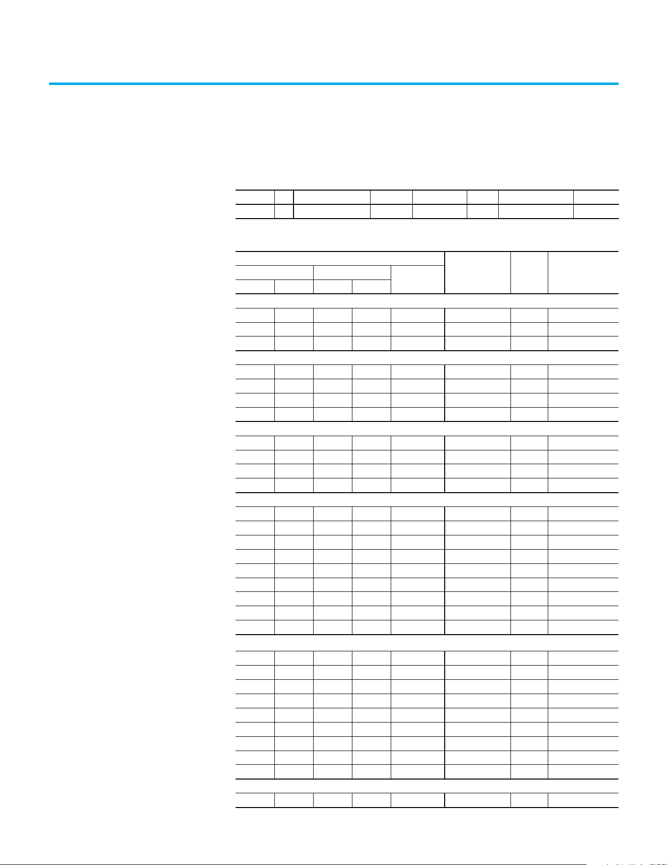
Rockwell Automation Publication 520-UM002E-EN-E - September 2024 131
Appendix B
Accessories and Dimensions
Product Selection
Table 1 - Catalog Number Description
25C - V 2P5 N 1 0 4
Drive Voltage Rating Rating Enclosure HIM Emission Class Version
Table 2 - PowerFlex 527 Drive Ratings
Output Ratings
Input
Voltage Range
Frame
Size
Catalog NumberNormal Duty Heavy Duty
Output
Current (A)
HP kW HP kW
100...120V AC (-15%, +10%) – 1-phase Input, 0...230V 3-phase Output
0.5 0.4 0.5 0.4 2.5 85...132 A 25C-V2P5N104
1.0 0.75 1.0 0.75 4.8 85...132 B 25C-V4P8N104
1.5 1.1 1.5 1.1 6.0 85...132 B 25C-V6P0N104
200...240V AC (-15%, +10%) – 1-phase Input, 0...230V 3-phase Output
0.5 0.4 0.5 0.4 2.5 170...264 A 25C-A2P5N104
1.0 0.75 1.0 0.75 4.8 170...264 A 25C-A4P8N104
2.0 1.5 2.0 1.5 8.0 170...264 B 25C-A8P0N104
3.0 2.2 3.0 2.2 11.0 170...264 B 25C-A011N104
200...240V AC (-15%, +10%) – 1-phase Input with EMC Filter, 0...230V 3-phase Output
0.5 0.4 0.5 0.4 2.5 170...264 A 25C-A2P5N114
1.0 0.75 1.0 0.75 4.8 170...264 A 25C-A4P8N114
2.0 1.5 2.0 1.5 8.0 170...264 B 25C-A8P0N114
3.0 2.2 3.0 2.2 11.0 170...264 B 25C-A011N114
200...240V AC (-15%, +10%) – 3-phase Input, 0...230V 3-phase Output
0.5 0.4 0.5 0.4 2.5 170...264 A 25C-B2P5N104
1.0 0.75 1.0 0.75 5.0 170...264 A 25C-B5P0N104
2.0 1.5 2.0 1.5 8.0 170...264 A 25C-B8P0N104
3.0 2.2 3.0 2.2 11.0 170...264 A 25C-B011N104
5.0 4.0 5.0 4.0 17.5 170...264 B 25C-B017N104
7.5 5.5 7.5 5.5 24.0 170...264 C 25C-B024N104
10.0 7.5 10.0 7.5 32.2 170...264 D 25C-B032N104
15.0 11.0 10.0 7.5 48.3 170...264 E 25C-B048N104
20.0 15.0 15.0 11.0 62.1 170...264 E 25C-B062N104
380...480V AC (-15%, +10%) – 3-phase Input, 0...460V 3-phase Output
(1)
0.5 0.4 0.5 0.4 1.4 323...528 A 25C-D1P4N104
1.0 0.75 1.0 0.75 2.3 323...528 A 25C-D2P3N104
2.0 1.5 2.0 1.5 4.0 323...528 A 25C-D4P0N104
3.0 2.2 3.0 2.2 6.0 323...528 A 25C-D6P0N104
5.0 4.0 5.0 4.0 10.5 323...528 B 25C-D010N104
7.5 5.5 7.5 5.5 13.0 323...528 C 25C-D013N104
10.0 7.5 10.0 7.5 17.0 323...528 C 25C-D017N104
15.0 11.0 15.0 11.0 24.0 323...528 D 25C-D024N104
20.0 15.0 15.0 11.0 30.0 323...528 D 25C-D030N104
380...480V AC (-15%, +10%) – 3-phase Input with EMC Filter, 0...460V 3-phase Output
0.5 0.4 0.5 0.4 1.4 323...528 A 25C-D1P4N114

132 Rockwell Automation Publication 520-UM002E-EN-E - September 2024
Appendix B Accessories and Dimensions
1.0 0.75 1.0 0.75 2.3 323...528 A 25C-D2P3N114
2.0 1.5 2.0 1.5 4.0 323...528 A 25C-D4P0N114
3.0 2.2 3.0 2.2 6.0 323...528 A 25C-D6P0N114
5.0 4.0 5.0 4.0 10.5 323...528 B 25C-D010N114
7.5 5.5 7.5 5.5 13.0 323...528 C 25C-D013N114
10.0 7.5 10.0 7.5 17.0 323...528 C 25C-D017N114
15.0 11.0 15.0 11.0 24.0 323...528 D 25C-D024N114
20.0 15.0 15.0 11.0 30.0 323...528 D 25C-D030N114
25.0 18.5 20.0 15.0 37.0 323...528 E 25C-D037N114
30.0 22.0 25.0 18.5 43.0 323...528 E 25C-D043N114
525...600V AC (-15%, +10%) – 3-phase Input, 0...575V 3-phase Output
0.5 0.4 0.5 0.4 0.9 446...660 A 25C-E0P9N104
1.0 0.75 1.0 0.75 1.7 446...660 A 25C-E1P7N104
2.0 1.5 2.0 1.5 3.0 446...660 A 25C-E3P0N104
3.0 2.2 3.0 2.2 4.2 446...660 A 25C-E4P2N104
5.0 4.0 5.0 4.0 6.6 446...660 B 25C-E6P6N104
7.5 5.5 7.5 5.5 9.9 446...660 C 25C-E9P9N104
10.0 7.5 10.0 7.5 12.0 446...660 C 25C-E012N104
15.0 11.0 15.0 11.0 19.0 446...660 D 25C-E019N104
20.0 15.0 15.0 11.0 22.0 446...660 D 25C-E022N104
25.0 18.5 20.0 15.0 27.0 446...660 E 25C-E027N104
30.0 22.0 25.0 18.5 32.0 446...660 E 25C-E032N104
(1) A non-filtered drive is not available for 380…480V AC 25 HP (18.5 kW) and 30 HP (22.0 kW) ratings. Filtered drives are available,
however you must verify that the application supports a filtered drive.
Table 2 - PowerFlex 527 Drive Ratings (Continued)
Output Ratings
Input
Voltage Range
Frame
Size
Catalog NumberNormal Duty Heavy Duty
Output
Current (A)
HP kW HP kW
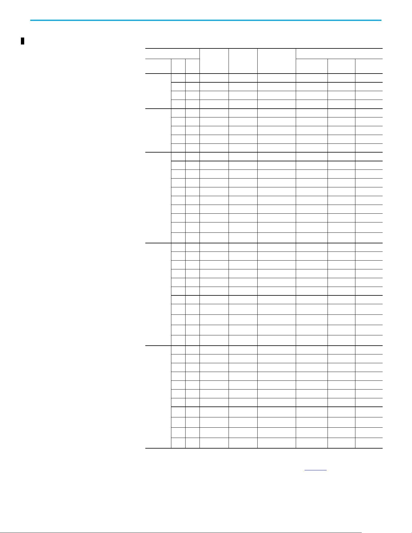
Rockwell Automation Publication 520-UM002E-EN-E - September 2024 133
Appendix B Accessories and Dimensions
Table 3 - Dynamic Brake Resistors
Drive Ratings
Minimum
Resistance,
Ω ±10%
Resistance,
Ω ±5%
Catalog
Number
(1)(2)
(1) The resistors that are listed in this table are rated for 5% duty cycle.
(2) Use of Rockwell Automation resistors is always recommended. The resistors that are listed have been carefully selected to optimize
performance in various applications. Alternative resistors may be used, however, care must be taken when making a selection. See
the PowerFlex Dynamic Braking Resistor Calculator Application Technique, publication PFLEX-AT001
.
Fuse Protection
(3)
(3) For IEC applications, DC Fuse is mandatory when these terminals are connected. Connect the fuse immerdiate to the terminal. Use
the specified part number. PV-xxxxxx fuse is from Bussman. 1000GH-xxx fuse is from Hinode.
Input
Voltage
HP kW
BR-
(4)
(4) For UL applications, DC fuse is mandatory at BR- terminal when use with a dynamic brake resistor.
DC+/BR+ DC-
100...120V
50/60 Hz
1-phase
0.25 0.2 56 91 AK-R2-091P500 PV-15A10F 1000GH-016 1000GH-016
0.5 0.4 56 91 AK-R2-091P500 PV-15A10F 1000GH-016 1000GH-016
1.0 0.75 56 91 AK-R2-091P500 PV-15A10F 1000GH-016 1000GH-016
1.5 1.1 41 91 AK-R2-091P500 PV-15A10F 1000GH-020 1000GH-020
200...240V
50/60 Hz
1-phase
0.25 0.2 56 91 AK-R2-091P500 PV-15A10F 1000GH-016 1000GH-016
0.5 0.4 56 91 AK-R2-091P500 PV-15A10F 1000GH-016 1000GH-016
1.0 0.75 56 91 AK-R2-091P500 PV-15A10F 1000GH-016 1000GH-016
2.0 1.5 41 91 AK-R2-091P500 PV-32ANH1 1000GH-025 1000GH-025
3.0 2.2 32 47 AK-R2-047P500 PV-32ANH1 1000GH-032 1000GH-032
200...240V
50/60 Hz
3-phase
0.25 0.2 56 91 AK-R2-091P500 PV-20A10F 1000GH-016 1000GH-016
0.5 0.4 56 91 AK-R2-091P500 PV-20A10F 1000GH-016 1000GH-016
1.0 0.75 56 91 AK-R2-091P500 PV-20A10F 1000GH-016 1000GH-016
2.0 1.5 41 91 AK-R2-091P500 PV-20A10F 1000GH-025 1000GH-025
3.0 2.2 32 47 AK-R2-047P500 PV-20A10F 1000GH-032 1000GH-032
5.0 4.0 18 47 AK-R2-047P500 PV-32ANH1 1000GH-050 1000GH-050
7.5 5.5 16 30 AK-R2-030P1K2 PV-40ANH1 1000GH-063 1000GH-063
10.0 7.5 14 30 AK-R2-030P1K2 1000GH-040 1000GH-080 1000GH-080
15.0 11.0 14 15
AK-R2-030P1K2
(5)
(5) Requires two resistors that are wired in parallel.
1000GH-050 1000GH-100 1000GH-100
20.0 15.0 10 15
AK-R2-030P1K2
(5)
1000GH-050 1000GH-125 1000GH-125
380...480V
50/60 Hz
3-phase
0.5 0.4 89 360 AK-R2-360P500 PV-10A10F 1000GH-016 1000GH-016
1.0 0.75 89 360 AK-R2-360P500 PV-10A10F 1000GH-016 1000GH-016
2.0 1.5 89 360 AK-R2-360P500 PV-10A10F 1000GH-016 1000GH-016
3.0 2.2 89 120 AK-R2-120P1K2 PV-10A10F 1000GH-016 1000GH-016
5.0 4.0 47 120 AK-R2-120P1K2 PV-20A10F 1000GH-032 1000GH-032
7.5 5.5 47 120 AK-R2-120P1K2 PV-32ANH1 1000GH-032 1000GH-032
10.0 7.5 47 120 AK-R2-120P1K2 PV-32ANH1 1000GH-040 1000GH-040
15.0 11.0 43 60
AK-R2-120P1K2
(5)
1000GH-025 1000GH-063 1000GH-063
20.0 15.0 43 60
AK-R2-120P1K2
(5)
1000GH-025 1000GH-080 1000GH-080
25.0 18.5 27 40
AK-R2-120P1K2
(6)
(6) Requires three resistors that are wired in parallel.
1000GH-040 1000GH-080 1000GH-080
30.0 22.0 27 40
AK-R2-120P1K2
(6)
1000GH-040 1000GH-080 1000GH-080
525...600V
50/60 Hz
3-phase
0.5 0.4 112 360 AK-R2-360P500 PV-10A10F 1000GH-016 1000GH-016
1.0 0.75 112 360 AK-R2-360P500 PV-10A10F 1000GH-016 1000GH-016
2.0 1.5 112 360 AK-R2-360P500 PV-10A10F 1000GH-016 1000GH-016
3.0 2.2 112 120 AK-R2-120P1K2 PV-10A10F 1000GH-016 1000GH-016
5.0 4.0 86 120 AK-R2-120P1K2 PV-12A10F 1000GH-025 1000GH-025
7.5 5.5 59 120 AK-R2-120P1K2 PV-20A10F 1000GH-025 1000GH-025
10.0 7.5 59 120 AK-R2-120P1K2 PV-20A10F 1000GH-032 1000GH-032
15.0 11.0 59 60
AK-R2-120P1K2
(5)
1000GH-025 1000GH-050 1000GH-050
20.0 15.0 59 60
AK-R2-120P1K2
(5)
1000GH-025 1000GH-063 1000GH-063
25.0 18.5 53 60
AK-R2-120P1K2
(5)
1000GH-040 1000GH-063 1000GH-063
30.0 22.0 34 40
AK-R2-120P1K2
(6)
1000GH-040 1000GH-063 1000GH-063
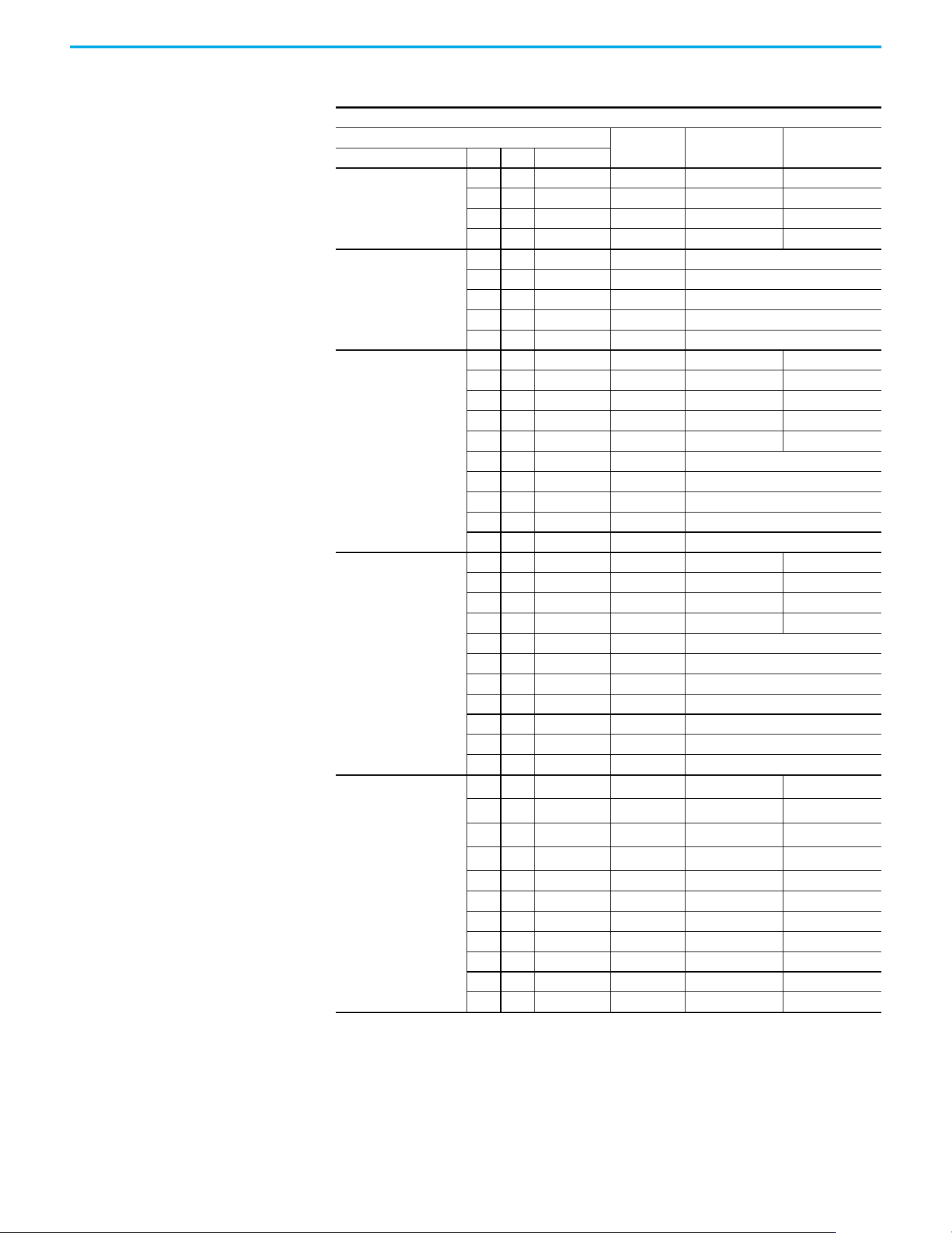
134 Rockwell Automation Publication 520-UM002E-EN-E - September 2024
Appendix B Accessories and Dimensions
Table 4 - EMC Line Filters
Short-circuit Current Rating = 100 kA
Drive Ratings
Frame Size
For 100 m
Catalog Number
For 150 m
(1)
Catalog Number
(1) Requires Series B filters to achieve 150 m (492 ft) rating.
Input Voltage HP kW Current (A)
100...120V
50/60 Hz
1-phase
0.25 0.2 1.6 A 25-RF011-AL —
0.5 0.4 2.5 A 25-RF011-AL —
1.0 0.75 4.8 B 25-RF023-BL —
1.5 1.1 6.0 B 25-RF023-BL —
200...240V
50/60 Hz
1-phase
0.25 0.2 1.6 A 25-RF011-AL
0.5 0.4 2.5 A 25-RF011-AL
1.0 0.75 4.8 A 25-RF011-AL
2.0 1.5 8.0 B 25-RF023-BL
3.0 2.2 11.0 B 25-RF023-BL
200...240V
50/60 Hz
3-phase
0.25 0.2 1.6 A 25-RF014-AL 25-RF021-BL
0.5 0.4 2.5 A 25-RF014-AL 25-RF021-BL
1.0 0.75 5.0 A 25-RF014-AL 25-RF021-BL
2.0 1.5 8.0 A 25-RF014-AL 25-RF021-BL
3.0 2.2 11.0 A 25-RF014-AL 25-RF021-BL
5.0 4.0 17.5 B 25-RF021-BL
7.5 5.5 24.0 C 25-RF027-CL
10.0 7.5 32.2 D 25-RF035-DL
15.0 11.0 48.3 E 25-RF056-EL
20.0 15.0 62.1 E 25-RF056-EL
380...480V
50/60 Hz
3-phase
0.5 0.4 1.4 A 25-RF7P5-AL 25-RF014-BL
1.0 0.75 2.3 A 25-RF7P5-AL 25-RF014-BL
2.0 1.5 4.0 A 25-RF7P5-AL 25-RF014-BL
3.0 2.2 6.0 A 25-RF7P5-AL 25-RF014-BL
5.0 4.0 10.5 B 25-RF014-BL
7.5 5.5 13.0 C 25-RF018-CL
10.0 7.5 17.0 C 25-RF018-CL
15.0 11.0 24.0 D 25-RF033-DL
20.0 15.0 30.0 D 25-RF033-DL
25.0 18.5 37.0 E 25-RF039-EL
30.0 22.0 43.0 E 25-RF039-E
525...600V
50/60 Hz
3-phase
0.5 0.4 0.9 A
25-RF8P0-BL
(2)
(2) The 600V drive rating must be matched with a Frame B Line Filter.
—
1.0 0.75 1.7 A
25-RF8P0-BL
(2)
—
2.0 1.5 3.0 A
25-RF8P0-BL
(2)
—
3.0 2.2 4.2 A
25-RF8P0-BL
(2)
—
5.0 4.0 6.6 B 25-RF8P0-BL —
7.5 5.5 9.9 C 25-RF014-CL —
10.0 7.5 12.0 C 25-RF014-CL —
15.0 11.0 19.0 D 25-RF027-DL —
20.0 15.0 22.0 D 25-RF027-DL —
25.0 18.5 27.0 E 25-RF029-EL —
30.0 22.0 32.0 E 25-RF029-EL —

Rockwell Automation Publication 520-UM002E-EN-E - September 2024 135
Appendix B Accessories and Dimensions
Replacement Parts
Table 5 - EMC Plates
Item Description
Frame
Size
Catalog
Number
EMC Plate Optional grounding plate for shielded cables.
A 25-EMC1-FA
B 25-EMC1-FB
C 25-EMC1-FC
D 25-EMC1-FD
E 25-EMC1-FE
Table 6 - IP 30/NEMA 1/UL Type 1 Kit
Item Description
Frame
Size
Catalog
Number
IP 30/NEMA 1/UL Type 1 Kit
Field installed kit. Converts drive to IP 30/NEMA 1/UL Type 1
enclosure. Includes conduit box with mounting screws and
plastic top panel.
A25-JBAA
B25-JBAB
C25-JBAC
D25-JBAD
E25-JBAE
Table 7 - Control Module Fan Kit
Item Description
Frame
Size
Catalog
Number
Control Module Fan Kit
For use with drive in environments with ambient
temperatures up to 70 °C (158 °F) or horizontal mounting.
A…D 25-FAN1-70C
E25-FAN2-70C
Table 8 - Incremental Encoder Input Option
Item Description
Catalog
Number
Incremental Encoder
Board
Interface to an external incremental encoder. 25-ENC-2
Table 9 - Bulletin 160 to PowerFlex 527 Mounting Adapter Plate
Item Description
B160
Frame
Size
Catalog
Number
Mounting Adapter Plate
For use with drive when replacing Bulletin 160 drives in existing
installations to a PowerFlex 520-deries drive. Select the catalog
number based on the frame size of your Bulletin 160 drive.
A25-MAP-FA
B25-MAP-FB
Table 10 - PowerFlex 527 Power Module
Item Description
PowerFlex 527
Power Module
Replacement power module for use with PowerFlex 527 drive.
Includes:
•Power Module
• Power Module Front Cover
• Power Terminal Guard
•Heatsink Fan
Table 11 - PowerFlex 527 Power Module
Output Ratings
Input
Voltage Range
Frame
Size
Catalog
Number
Normal Duty Heavy Duty
Output
Current (A)
HP kW HP kW
100...120V AC (-15%, +10%) – 1-phase Input, 0...230V 3-phase Output
0.5 0.4 0.5 0.4 2.5 85…132 A 25-PM1-V2P5
1.0 0.75 1.0 0.75 4.8 85…132 B 25-PM1-V4P8

136 Rockwell Automation Publication 520-UM002E-EN-E - September 2024
Appendix B Accessories and Dimensions
1.5 1.1 1.5 1.1 6.0 85…132 B 25-PM1-V6P0
200…240V AC (-15%, +10%) – 1-phase Input, 0…230V 3-phase Output
0.5 0.4 0.5 0.4 2.5 170…264 A 25-PM1-A2P5
1.0 0.75 1.0 0.75 4.8 170…264 A 25-PM1-A4P8
2.0 1.5 2.0 1.5 8.0 170…264 B 25-PM1-A8P0
3.0 2.2 3.0 2.2 11.0 170…264 B 25-PM1-A011
200…240V AC (-15%, +10%) – 1-phase Input with EMC Filter, 0…230V 3-phase Output
0.5 0.4 0.5 0.4 2.5 170…264 A 25-PM2-A2P5
1.0 0.75 1.0 0.75 4.8 170…264 A 25-PM2-A4P8
2.0 1.5 2.0 1.5 8.0 170…264 B 25-PM2-A8P0
3.0 2.2 3.0 2.2 11.0 170…264 B 25-PM2-A011
200…240V AC (-15%, +10%) – 3-phase Input, 0…230V 3-phase Output
0.5 0.4 0.5 0.4 2.5 170…264 A 25-PM1-B2P5
1.0 0.75 1.0 0.75 5.0 170…264 A 25-PM1-B5P0
2.0 1.5 2.0 1.5 8.0 170…264 A 25-PM1-B8P0
3.0 2.2 3.0 2.2 11.0 170…264 A 25-PM1-B011
5.0 4.0 5.0 4.0 17.5 170…264 B 25-PM1-B017
7.5 5.5 7.5 5.5 24.0 170…264 C 25-PM1-B024
10.0 7.5 10.0 7.5 32.2 170…264 D 25-PM1-B032
15.0 11.0 10.0 7.5 48.3 170…264 E 25-PM1-B048
20.0 15.0 15.0 11.0 62.1 170…264 E 25-PM1-B062
380…480V AC (-15%, +10%) – 3-phase Input, 0...460V 3-phase Output
0.5 0.4 0.5 0.4 1.4 323…528 A 25-PM1-D1P4
1.0 0.75 1.0 0.75 2.3 323…528 A 25-PM1-D2P3
2.0 1.5 2.0 1.5 4.0 323…528 A 25-PM1-D4P0
3.0 2.2 3.0 2.2 6.0 323…528 A 25-PM1-D6P0
5.0 4.0 5.0 4.0 10.5 323…528 B 25-PM1-D010
7.5 5.5 7.5 5.5 13.0 323…528 C 25-PM1-D013
10.0 7.5 10.0 7.5 17.0 323…528 C 25-PM1-D017
15.0 11.0 15.0 11.0 24.0 323…528 D 25-PM1-D024
20.0 15.0 15.0 11.0 30.0 323…528 D 25-PM1-D030
380…480V AC (-15%, +10%) – 3-phase Input with EMC Filter, 0...460V 3-phase Output
0.5 0.4 0.5 0.4 1.4 323…528 A 25-PM2-D1P4
1.0 0.75 1.0 0.75 2.3 323…528 A 25-PM2-D2P3
2.0 1.5 2.0 1.5 4.0 323…528 A 25-PM2-D4P0
3.0 2.2 3.0 2.2 6.0 323…528 A 25-PM2-D6P0
5.0 4.0 5.0 4.0 10.5 323…528 B 25-PM2-D010
7.5 5.5 7.5 5.5 13.0 323…528 C 25-PM2-D013
10.0 7.5 10.0 7.5 17.0 323…528 C 25-PM2-D017
15.0 11.0 15.0 11.0 24.0 323…528 D 25-PM2-D024
20.0 15.0 15.0 11.0 30.0 323…528 D 25-PM2-D030
25.0 18.5 20.0 15.0 37.0 323…528 E 25-PM2-D037
30.0 22.0 25.0 18.5 43.0 323…528 E 25-PM2-D043
525…600V AC (-15%, +10%) – 3-phase Input, 0…575V 3-phase Output
0.5 0.4 0.5 0.4 0.9 446…660 A 25-PM1-E0P9
1.0 0.75 1.0 0.75 1.7 446…660 A 25-PM1-E1P7
2.0 1.5 2.0 1.5 3.0 446…660 A 25-PM1-E3P0
3.0 2.2 3.0 2.2 4.2 446…660 A 25-PM1-E4P2
5.0 4.0 5.0 4.0 6.6 446…660 B 25-PM1-E6P6
Table 11 - PowerFlex 527 Power Module (Continued)
Output Ratings
Input
Voltage Range
Frame
Size
Catalog
Number
Normal Duty Heavy Duty
Output
Current (A)
HP kW HP kW
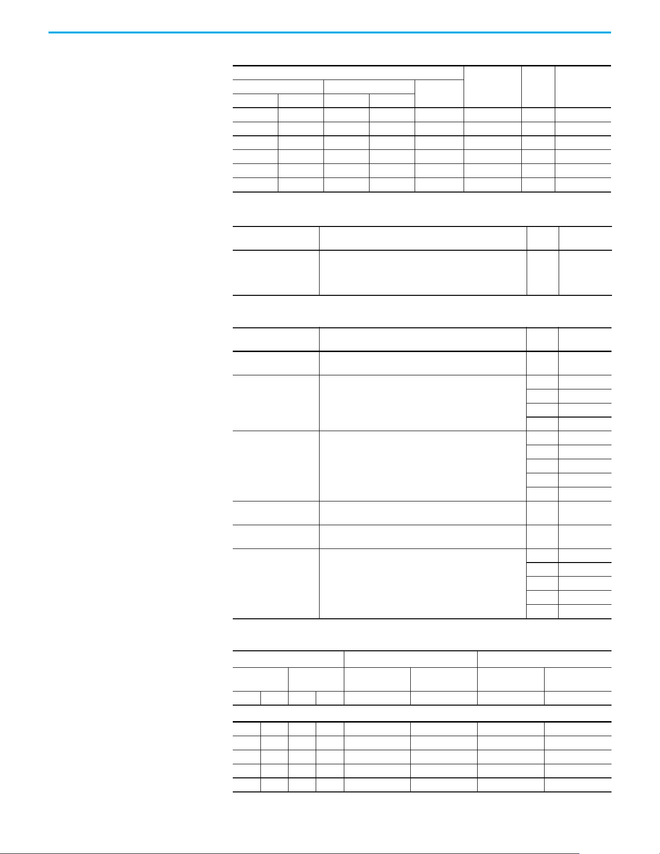
Rockwell Automation Publication 520-UM002E-EN-E - September 2024 137
Appendix B Accessories and Dimensions
7.5 5.5 7.5 5.5 9.9 446…660 C 25-PM1-E9P9
10.0 7.5 10.0 7.5 12.0 446…660 C 25-PM1-E012
15.0 11.0 15.0 11.0 19.0 446…660 D 25-PM1-E019
20.0 15.0 15.0 11.0 22.0 446…660 D 25-PM1-E022
25.0 18.5 20.0 15.0 27.0 446…660 E 25-PM1-E027
30.0 22.0 25.0 18.5 32.0 446…660 E 25-PM1-E032
Table 12 - PowerFlex 527 Control Module
Item Description
Frame
Size
Catalog
Number
PowerFlex 527
Control Module
Replacement control module for use with PowerFlex 527 drives.
Includes:
•Control module
• Control module front cover
A…E 25C-CTM1
Table 13 - Other Parts
Item Description
Frame
Size
Catalog
Number
PowerFlex 527 Control
Module Front Cover
Replacement cover for the control module I/O terminals and
EtherNet/IP ports.
A...E 25C-CTMFC1
PowerFlex 520-Series
Power Module Front Cover
Replacement cover for the PowerFlex 520-series power module
B 25-PMFC-FB
C 25-PMFC-FC
D 25-PMFC-FD
E 25-PMFC-FE
PowerFlex 520-Series
Power Terminal Guard
Replacement finger guard for power terminals
A 25-PTG1-FA
B 25-PTG1-FB
C 25-PTG1-FC
D 25-PTG1-FD
E 25-PTG1-FE
PowerFlex 527 Removable
Terminal Blocks Kit
Replacement terminal blocks for control wiring A…E 25C-RCTB
PowerFlex 527 Control
Module Internal Fan Kit
Replacement internal fan for the control module A…E 25C-FAN2-INT
PowerFlex 520-Series
Heatsink Fan Kit
Replacement fan for drive power module
A 25-FAN1-FA
B 25-FAN1-FB
C 25-FAN1-FC
D 25-FAN1-FD
E 25-FAN1-FE
Table 14 - Bulletin 1321-3R Series Line Reactors
Output Ratings
(1)
Input Line Reactor
(2)(3)
Output Line Reactor
Normal Duty Heavy Duty
IP00
(Open Style)
IP11
(NEMA/UL Type 1)
IP00
(Open Style)
IP11
(NEMA/UL Type 1)
HP kW HP kW Catalog Number Catalog Number Catalog Number Catalog Number
200…240V 50/60 Hz 1-phase
(4)
0.25 0.2 0.25 0.2 1321-3R4-A 1321-3RA4-A 1321-3R2-D 1321-3RA2-D
0.5 0.4 0.5 0.4 1321-3R8-A 1321-3RA8-A 1321-3R2-D 1321-3RA2-D
1.0 0.75 1.0 0.75 1321-3R8-A 1321-3RA8-A 1321-3R4-A 1321-3RA4-A
2.0 1.5 2.0 1.5 1321-3R18-A 1321-3RA18-A 1321-3R8-A 1321-3RA8-A
3.0 2.2 3.0 2.2 1321-3R18-A 1321-3RA18-A 1321-3R12-A 1321-3RA12-A
Table 11 - PowerFlex 527 Power Module (Continued)
Output Ratings
Input
Voltage Range
Frame
Size
Catalog
Number
Normal Duty Heavy Duty
Output
Current (A)
HP kW HP kW
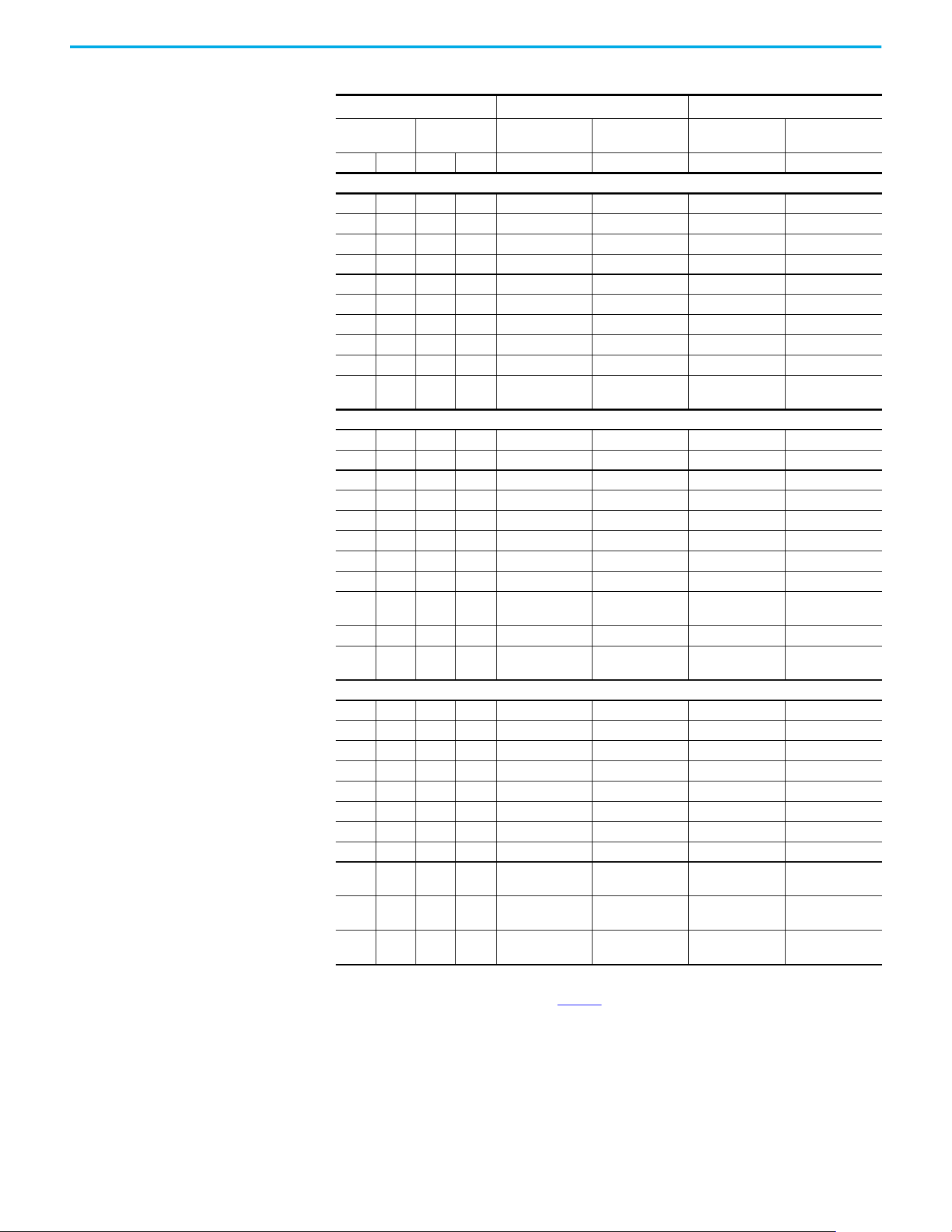
138 Rockwell Automation Publication 520-UM002E-EN-E - September 2024
Appendix B Accessories and Dimensions
200...240V 50/60 Hz 3-phase
0.25 0.2 0.25 0.2 1321-3R2-D 1321-3RA2-D 1321-3R2-D 1321-3RA2-D
0.5 0.4 0.5 0.4 1321-3R2-D 1321-3RA2-D 1321-3R2-D 1321-3RA2-D
1.0 0.75 1.0 0.75 1321-3R4-A 1321-3RA4-A 1321-3R4-A 1321-3RA4-A
2.0 1.5 2.0 1.5 1321-3R8-A 1321-3RA8-A 1321-3R8-A 1321-3RA8-A
3.0 2.2 3.0 2.2 1321-3R12-A 1321-3RA12-A 1321-3R12-A 1321-3RA12-A
5.0 4.0 5.0 4.0 1321-3R18-A 1321-3RA18-A 1321-3R18-A 1321-3RA18-A
7.5 5.5 7.5 5.5 1321-3R25-A 1321-3RA25-A 1321-3R25-A 1321-3RA25-A
10.0 7.5 10.0 7.5 1321-3R35-A 1321-3RA35-A 1321-3R35-A 1321-3RA35-A
15.0 11.0 10.0 7.5 1321-3R45-A 1321-3RA45-A 1321-3R45-A 1321-3RA45-A
20.0 15.0 15.0 11.0
1321-3R55-A (ND)
1321-3R45-A (HD)
1321-3RA55-A (ND)
1321-3RA45-A (HD)
1321-3R55-A (ND)
1321-3R45-A (HD)
1321-3RA55-A (ND)
1321-3RA45-A (HD)
380…480V 50/60 Hz 3-phase
0.5 0.4 0.5 0.4 1321-3R2-B 1321-3RA2-B 1321-3R2-B 1321-3RA2-B
1.0 0.75 1.0 0.75 1321-3R4-C 1321-3RA4-C 1321-3R4-C 1321-3RA4-C
2.0 1.5 2.0 1.5 1321-3R4-B 1321-3RA4-B 1321-3R4-B 1321-3RA4-B
3.0 2.2 3.0 2.2 1321-3R8-C 1321-3RA8-C 1321-3R8-C 1321-3RA8-C
5.0 4.0 5.0 4.0 1321-3R12-B 1321-3RA12-B 1321-3R12-B 1321-3RA12-B
7.5 5.5 7.5 5.5 1321-3R12-B 1321-3RA12-B 1321-3R12-B 1321-3RA12-B
10.0 7.5 10.0 7.5 1321-3R18-B 1321-3RA18-B 1321-3R18-B 1321-3RA18-B
15.0 11.0 15.0 11.0 1321-3R25-B 1321-3RA25-B 1321-3R25-B 1321-3RA25-B
20.0 15.0 15.0 11.0
1321-3R35-B (ND)
1321-3R25-B (HD)
1321-3RA35-B (ND)
1321-3RA25-B (HD)
1321-3R35-B (ND)
1321-3R25-B (HD)
1321-3RA35-B (ND)
1321-3RA25-B (HD)
25.0 18.5 20.0 15.0 1321-3R35-B 1321-3RA35-B 1321-3R35-B 1321-3RA35-B
30.0 22.0 25.0 18.5
1321-3R45-B (ND)
1321-3R35-B (HD)
1321-3RA45-B (ND)
1321-3RA35-B (HD)
1321-3R45-B (ND)
1321-3R35-B (HD)
1321-3RA45-B (ND)
1321-3RA35-B (HD)
525…600V 50/60 Hz 3-phase
0.5 0.4 0.5 0.4 1321-3R1-C 1321-3RA1-C 1321-3R1-C 1321-3RA1-C
1.0 0.75 1.0 0.75 1321-3R2-B 1321-3RA2-B 1321-3R2-B 1321-3RA2-B
2.0 1.5 2.0 1.5 1321-3R4-C 1321-3RA4-C 1321-3R4-C 1321-3RA4-C
3.0 2.2 3.0 2.2 1321-3R4-B 1321-3RA4-B 1321-3R4-B 1321-3RA4-B
5.0 4.0 5.0 4.0 1321-3R8-C 1321-3RA8-C 1321-3R8-C 1321-3RA8-C
7.5 5.5 7.5 5.5 1321-3R12-B 1321-3RA12-B 1321-3R12-B 1321-3RA12-B
10.0 7.5 10.0 7.5 1321-3R12-B 1321-3RA12-B 1321-3R12-B 1321-3RA12-B
15.0 11.0 15.0 11.0 1321-3R18-B 1321-3RA18-B 1321-3R18-B 1321-3RA18-B
20.0 15.0 15.0 11.0
1321-3R25-B (ND)
1321-3R18-B (HD)
1321-3RA25-B (ND)
1321-3RA18-B (HD)
1321-3R25-B (ND)
1321-3R18-B (HD)
1321-3RA25-B (ND)
1321-3RA18-B (HD)
25.0 18.5 20.0 15.0
1321-3R35-C (ND)
1321-3R25-C (HD)
1321-3RA35-C (ND)
1321-3RA25-C (HD)
1321-3R35-C (ND)
1321-3R25-C (HD)
1321-3RA35-C (ND)
1321-3RA25-C (HD)
30.0 22.0 25.0 18.5
1321-3R35-C (ND)
1321-3R25-B (HD)
1321-3RA35-C (ND)
1321-3RA25-B (HD)
1321-3R35-C (ND)
1321-3R25-B (HD)
1321-3RA35-C (ND)
1321-3RA25-B (HD)
(1) Normal Duty and Heavy Duty ratings for 15 HP (11 kW) and below are identical except for 200…240V 3-phase 15 HP (11 kW) drive.
(2) Catalog numbers that are listed are for 3% impedance at 60 Hz. 5% impedance reactor types are also available. See the 1321 Power
Conditioning Products Technical Data, publication 1321-TD001
.
(3) Input line reactors were sized based on the NEC fundamental motor amps. Output line reactors were sized based on the VFD rated
output currents.
(4) Standard 3-phase reactors can be used for 1-phase applications by routing each of the two supply conductors through an outside
coil and leaving the center open.
Table 14 - Bulletin 1321-3R Series Line Reactors (Continued)
Output Ratings
(1)
Input Line Reactor
(2)(3)
Output Line Reactor
Normal Duty Heavy Duty
IP00
(Open Style)
IP11
(NEMA/UL Type 1)
IP00
(Open Style)
IP11
(NEMA/UL Type 1)
HP kW HP kW Catalog Number Catalog Number Catalog Number Catalog Number
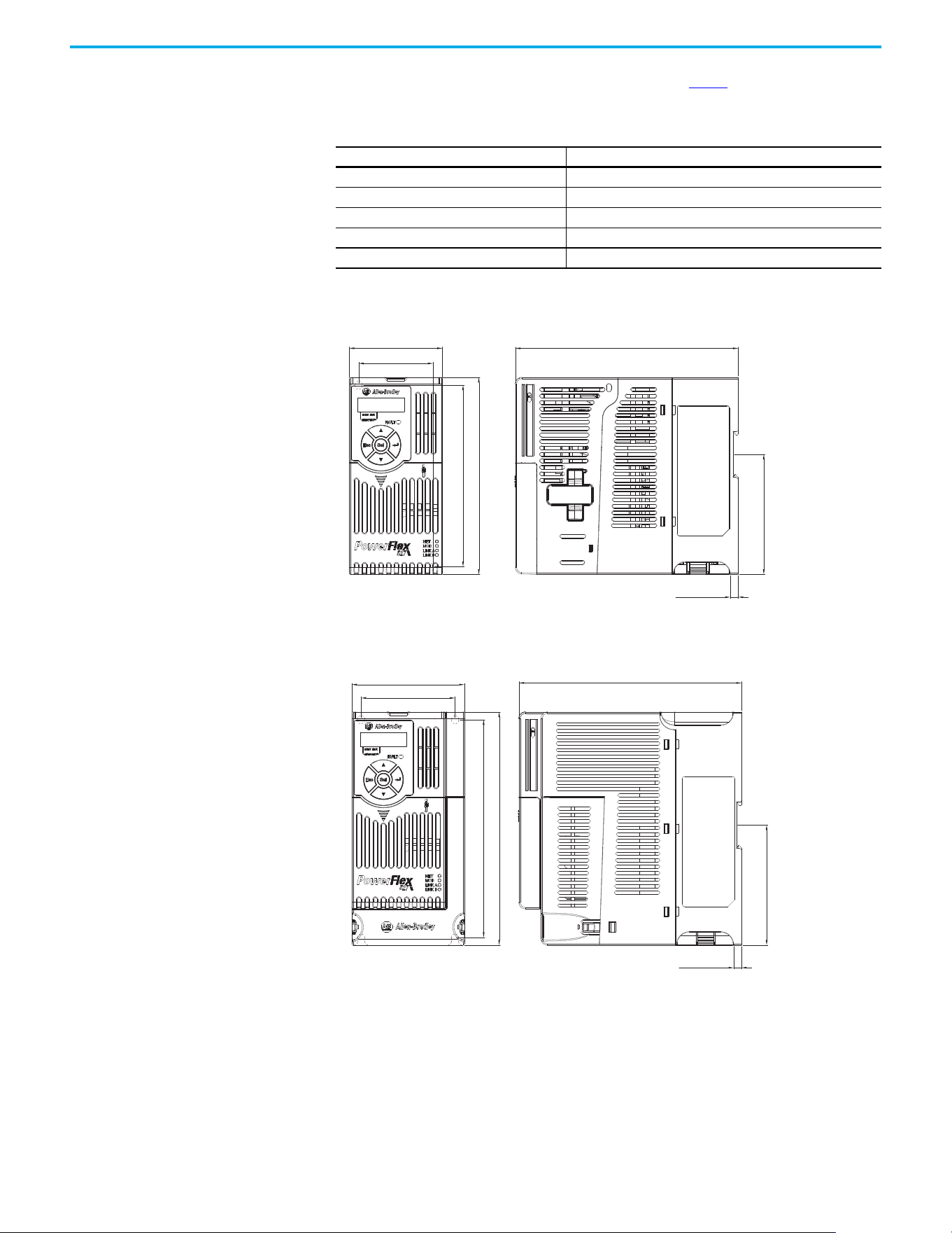
Rockwell Automation Publication 520-UM002E-EN-E - September 2024 139
Appendix B Accessories and Dimensions
Product Dimensions The PowerFlex 527 drive is available in five frame sizes. See the Table 2 for information on power
ratings.
IP 20/Open Type – Frame A
IP 20/Open Type – Frame B
Table 15 - PowerFlex 527 Drive Weight
Frame Size Weight (kg/lb)
A1.1 / 2.4
B1.6 / 3.5
C2.3 / 5.0
D3.9 / 8.6
E 12.9 / 28.4
72.0 (2.83)
57.5 (2.26)
172.0 (6.77)
140.0 (5.51)
152.0 (5.98)
92.7 (3.65)
6.0 (0.24)
Dimensions are in millimeters and (inches)
87.0 (3.43)
72.5 (2.85)
172.0 (6.77)
6.0 (0.24)
92.7 (3.65)
168.0 (6.61)
180.0 (7.09)
Dimensions are in millimeters and (inches)
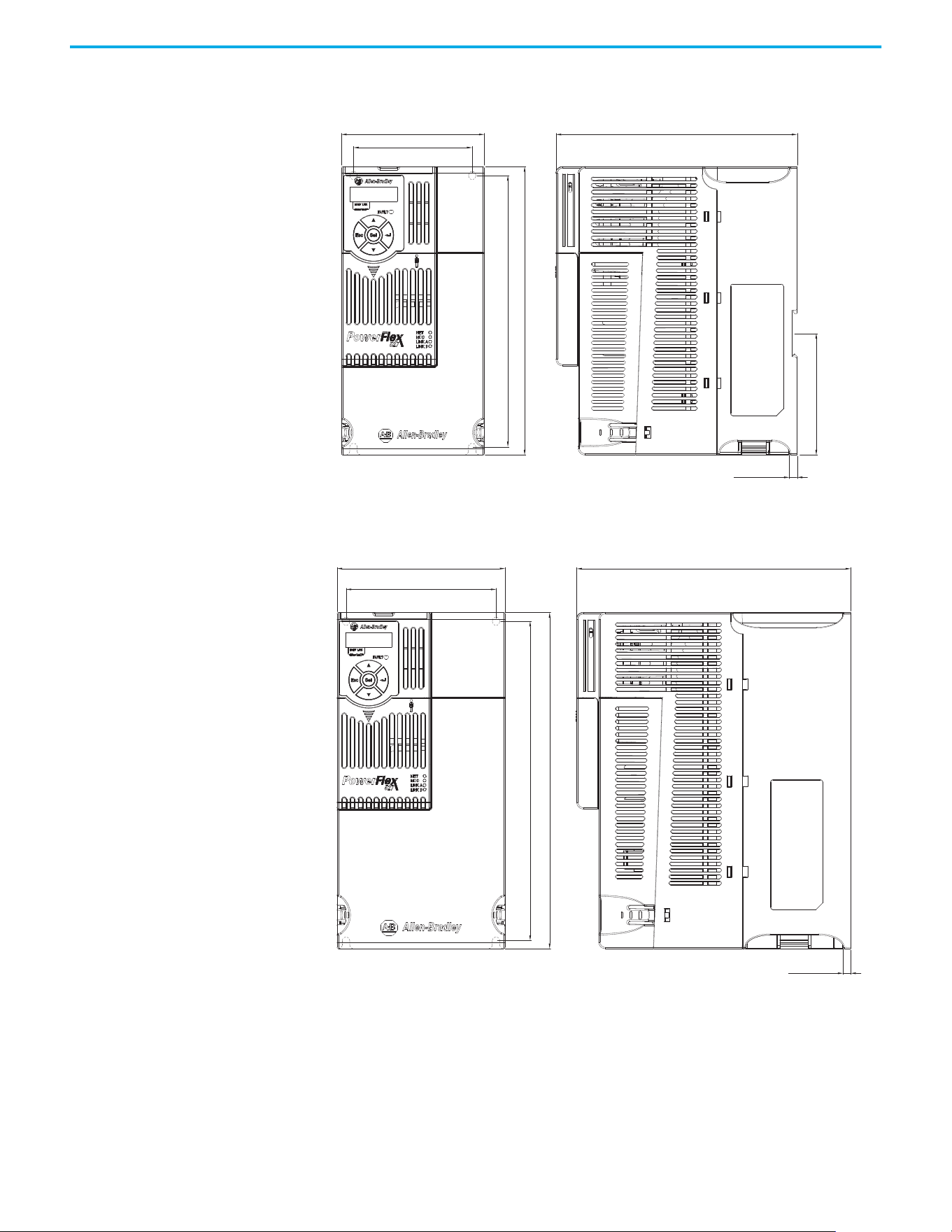
140 Rockwell Automation Publication 520-UM002E-EN-E - September 2024
Appendix B Accessories and Dimensions
IP 20/Open Type – Frame C
IP 20/Open Type – Frame D
109.0 (4.29)
90.5 (3.56)
207.0 (8.15)
220.0 (8.66)
184.0 (7.24)
6.0 (0.24)
92.7 (3.65)
Dimensions are in millimeters and (inches)
130.0 (5.12)
116.0 (4.57)
247.0 (9.72)
260.0 (10.24)
6.0 (0.24)
212.0 (8.35)
Dimensions are in millimeters and (inches)
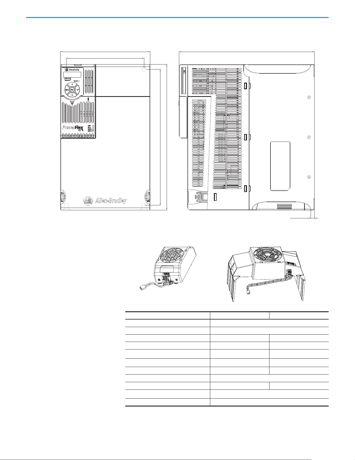
Rockwell Automation Publication 520-UM002E-EN-E - September 2024 141
Appendix B Accessories and Dimensions
IP 20/Open Type – Frame E
Control Module Fan Kit
185.0 (7.28)
160.0 (6.30)
279.0 (10.98)
280.0 (11.02)
300.0 (11.81)
7.6 (0.30)
Dimensions are in millimeters and (inches)
Specifications 25-FAN1-70C 25-FAN2-70C
Rated Voltage 24V DC
Operation Voltage 14…27.6V DC
Input Current 0.1 A 0.15 A
Speed (Reference) 7000 rpm 4500 ± 10% rpm
Maximum Airflow (At zero static pressure)
0.575 m
3
/min 1.574 m
3
/min
Maximum Air Pressure (At zero airflow)
7.70 mm H
2
O 9.598 mm H
2
O
Acoustical Noise 40.5 dBA 46.0 dBA
Insulation Type UL Class A
Frame Size Frame A…D Frame E
Wire Size
0.32 mm
2
(22 AWG)
Torque 0.29…0.39 N•m (2.6…3.47 lb•in)
25-FAN1-70C 25-FAN2-70C
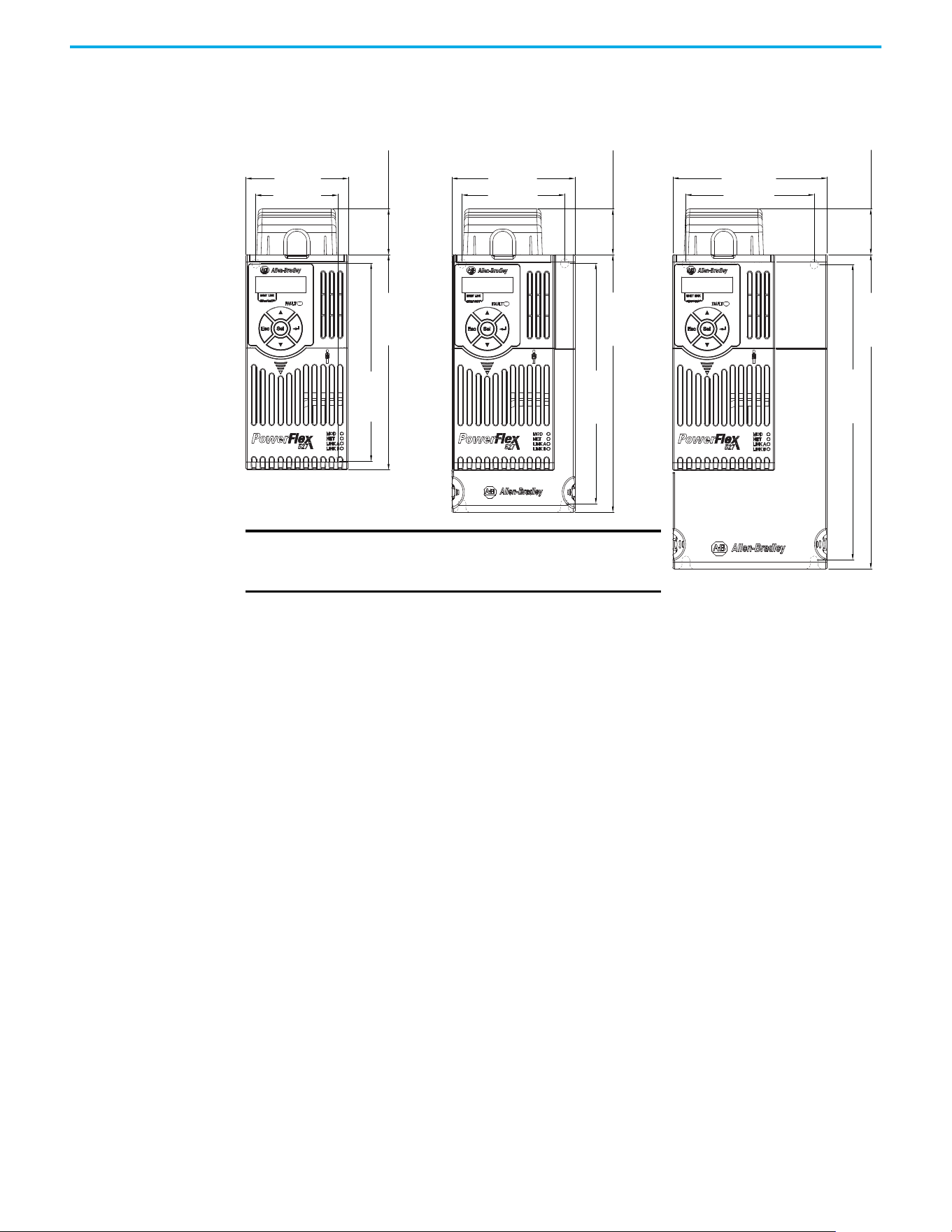
142 Rockwell Automation Publication 520-UM002E-EN-E - September 2024
Appendix B Accessories and Dimensions
IP 20/Open Type with Control Module Fan Kit – Frame A...C
72.0 (2.83)
32.0 (1.26)
140.0 (5.51)
152.0 (5.98)
57.5 (2.26)
87.0 (3.43)
32.0 (1.26)
180.0 (7.09)
168.0 (6.61)
72.5 (2.85)
109.0 (4.29)
32.0 (1.26)
220.0 (8.66)
207.0 (8.15)
90.5 (3.56)
Frame A Frame B
Dimensions are in millimeters and (inches)
Frame C
IMPORTANT An external 24V DC power source is required when
using the Control Module Fan Kit with drive frames A,
B, and C.
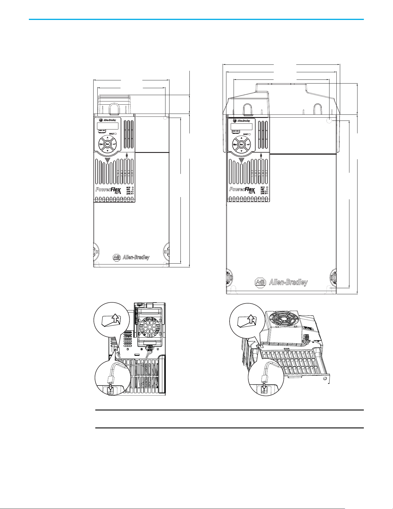
Rockwell Automation Publication 520-UM002E-EN-E - September 2024 143
Appendix B Accessories and Dimensions
IP 20/Open Type with Control Module Fan Kit – Frame D…E
130.0 (5.12)
32.0 (1.26)
260.0 (10.24)
247.0 (9.72)
116.0 (4.57)
185.0 (7.28)
196.0 (7.72)
52.0 (2.05)
300.0 (11.81)
280.0 (11.02)
160.0 (6.30)
Dimensions are in millimeters and (inches)
Frame D Frame E
IMPORTANT Remove the label to access the built-in 24V supply on drive frames D and E for use with the
Control Module Fan Kit.
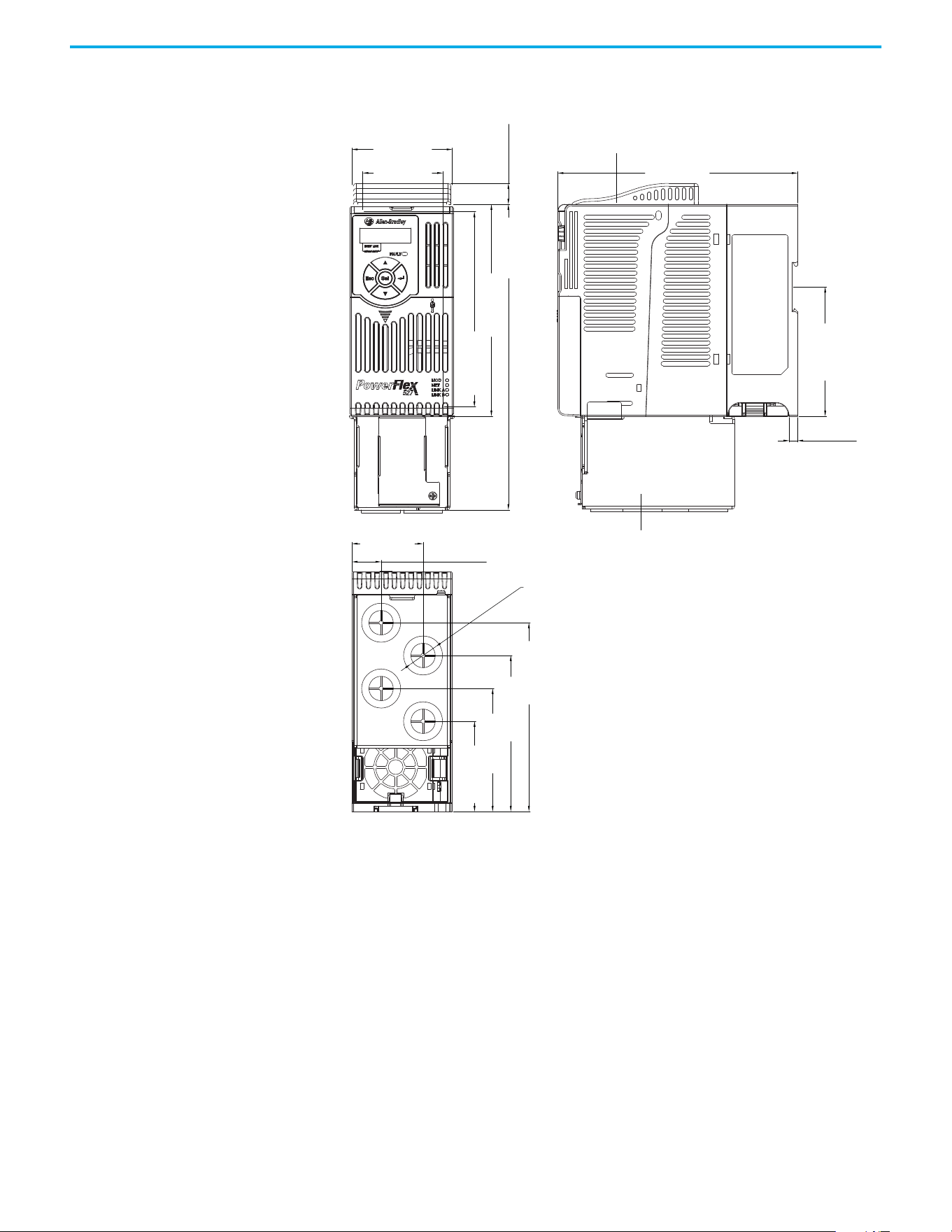
144 Rockwell Automation Publication 520-UM002E-EN-E - September 2024
Appendix B Accessories and Dimensions
IP 30/NEMA 1/UL Type 1 – Frame A
72.0 (2.83)
172.0 (6.77)
6.0 (0.24)
51.1 (2.01)
21.0 (0.82)
57.5 (2.26)
15.0 (0.59)
219.0 (8.62)
92.7 (3.65)
140.0 (5.51)
135.4 (5.33)
111.9 (4.41)
88.2 (3.47)
64.7 (2.55)
152.0 (5.98)
ø21.5 (ø0.85)
Dimensions are in millimeters and (inches)
IP 30/NEMA 1/ UL Type 1 conduit box
IP 30/NEMA 1/ UL Type 1 top panel
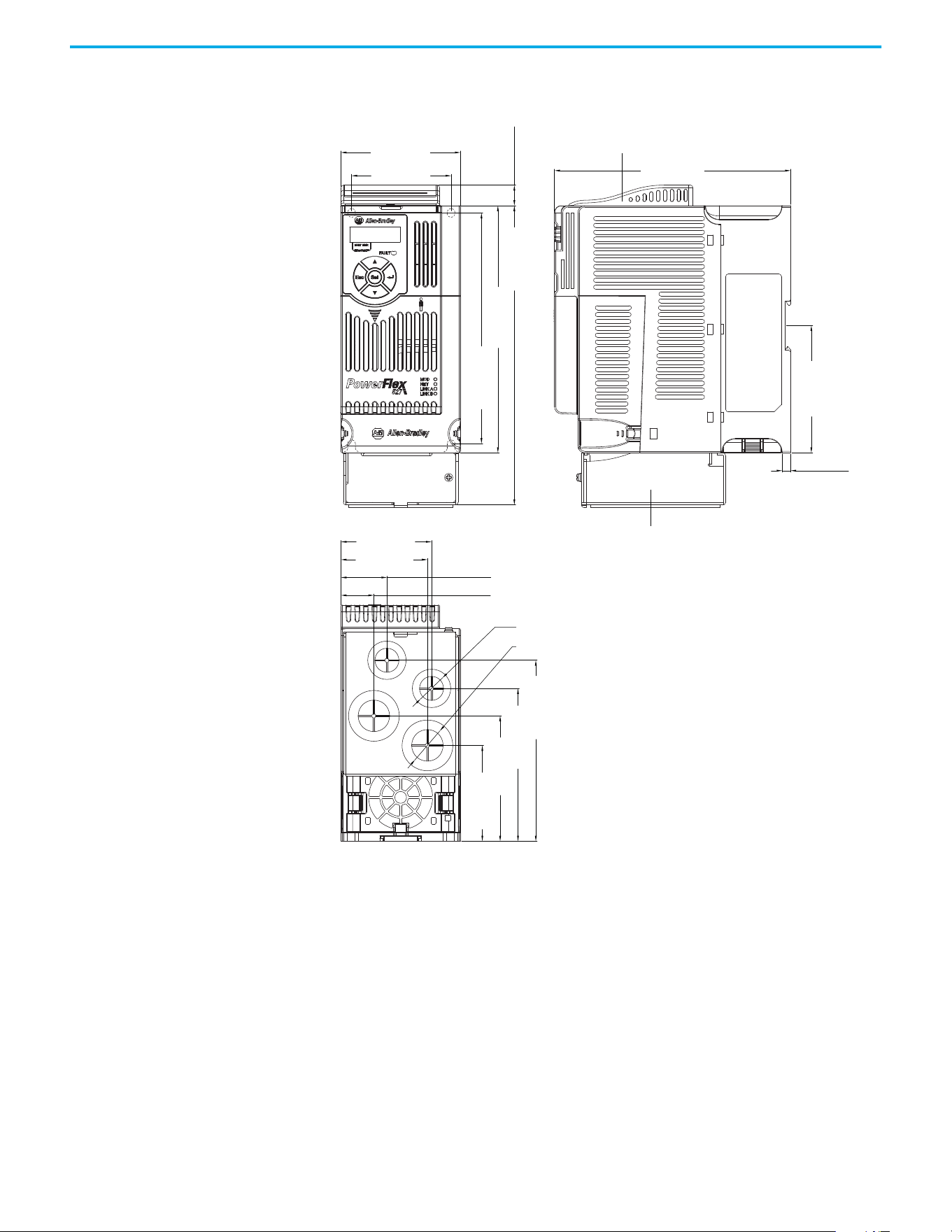
Rockwell Automation Publication 520-UM002E-EN-E - September 2024 145
Appendix B Accessories and Dimensions
IP 30/NEMA 1/UL Type 1 – Frame B
87.0 (3.43)
172.0 (6.77)
6.1 (0.24)
72.5 (2.85)
66.1 (2.60)
63.1 (2.48)
33.5 (1.32)
23.9 (0.94)
15.0 (0.59)
92.7 (3.65)
218.0 (8.58)
180.0 (7.09)
168.0 (6.61)
128.5 (5.06)
108.5 (4.27)
88.3 (3.48)
67.3 (2.65)
ø21.5 (ø0.85)
ø27.5 (ø1.08)
Dimensions are in millimeters and (inches)
IP 30/NEMA 1/ UL Type 1 conduit box
IP 30/NEMA 1/ UL Type 1 top panel
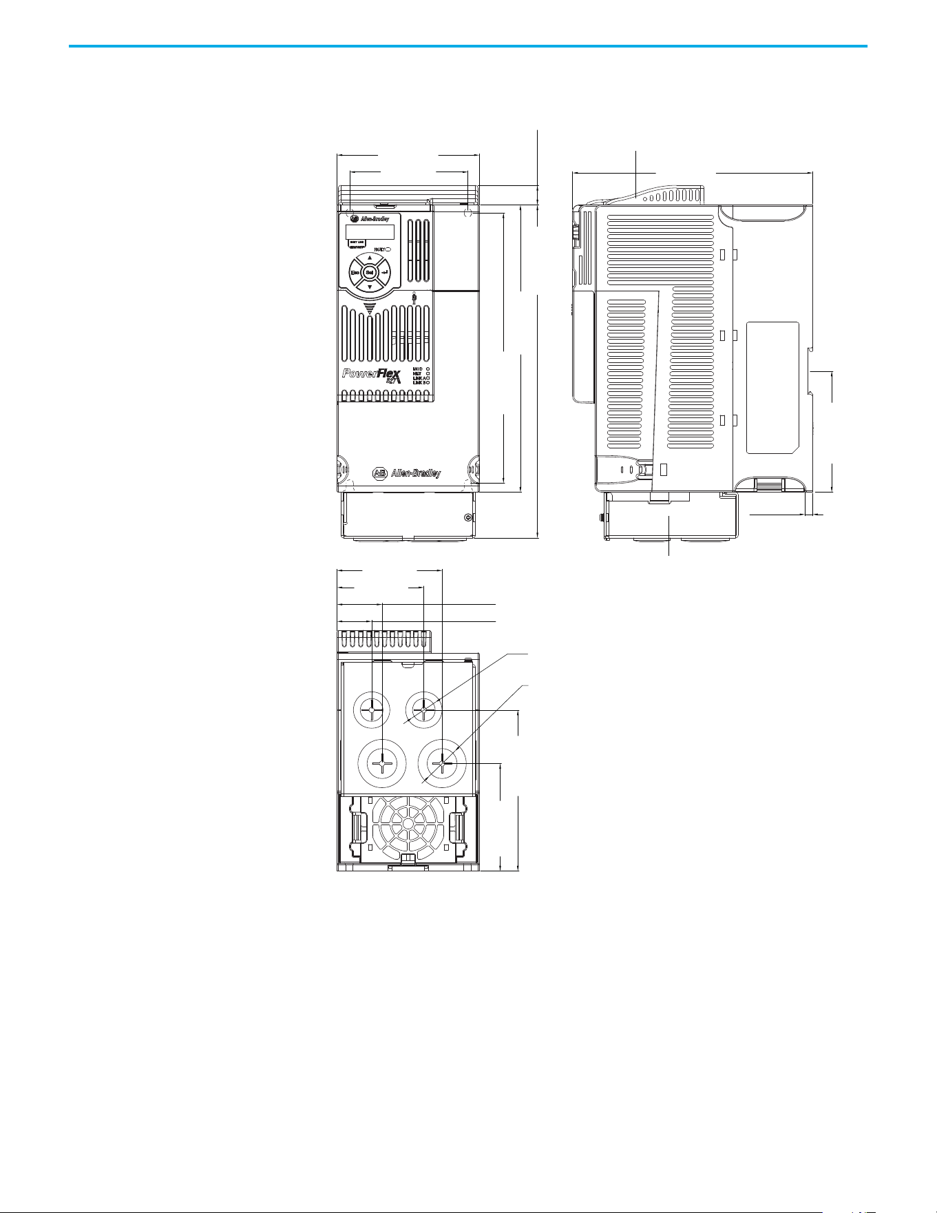
146 Rockwell Automation Publication 520-UM002E-EN-E - September 2024
Appendix B Accessories and Dimensions
IP 30/NEMA 1/UL Type 1 – Frame C
109.0 (4.29)
184.0 (7.24)
15.0 (0.59)
207.0 (8.15)
123.3 (4.85)
82.2 (3.24)
222.0 (8.66)
92.7 (3.65)
255.0 (10.04)
90.5 (3.56)
80.5 (3.17)
66.5 (2.62)
34.5 (1.36)
26.5 (1.04)
6.0 (0.24)
ø21.5 (ø0.85)
ø27.5 (ø1.08)
Dimensions are in millimeters and (inches)
IP 30/NEMA 1/ UL Type 1 conduit box
IP 30/NEMA 1/ UL Type 1 top panel
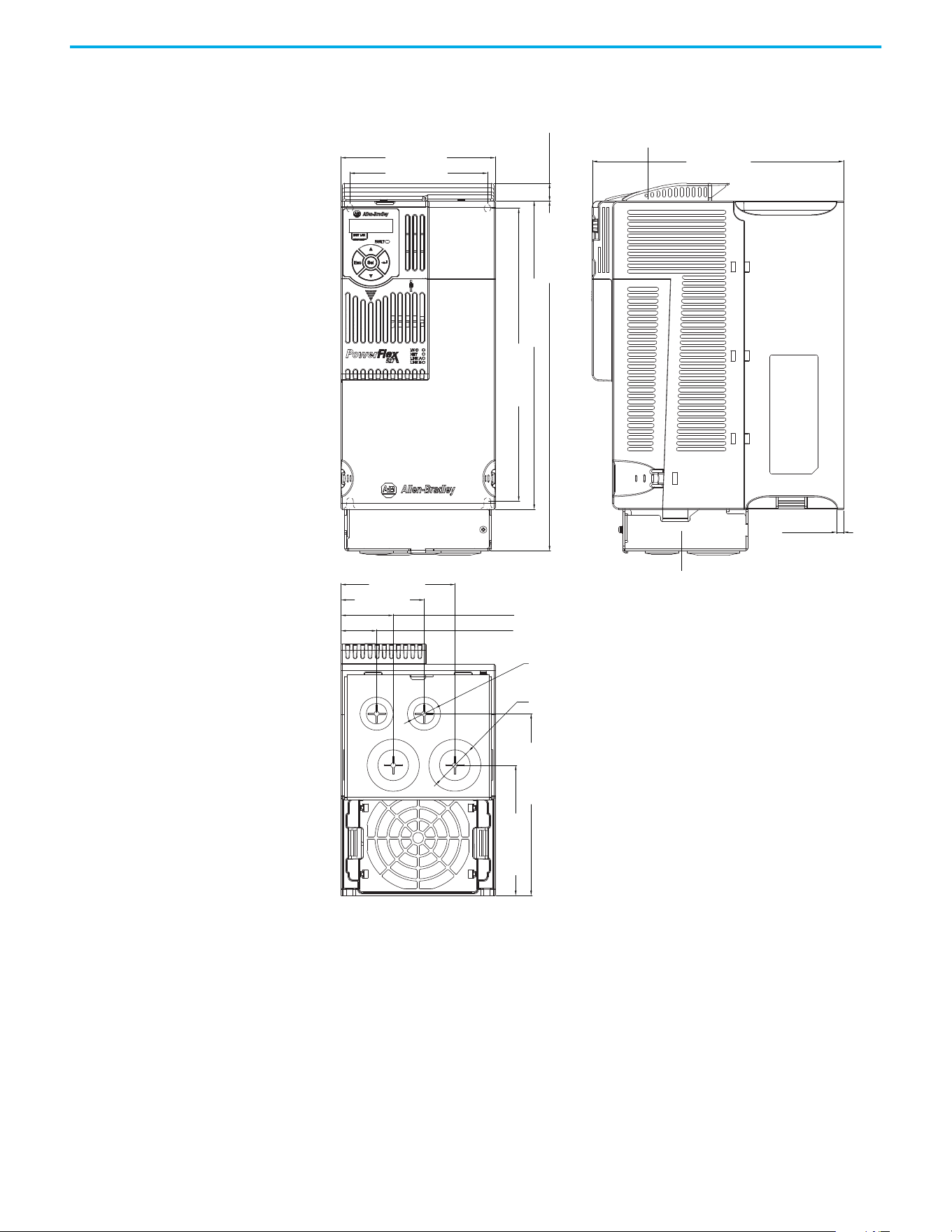
Rockwell Automation Publication 520-UM002E-EN-E - September 2024 147
Appendix B Accessories and Dimensions
IP 30/NEMA 1/UL Type 1 – Frame D
130.0 (5.12)
212.0 (8.35)
6.0 (0.24)
260.0 (10.24)
295.0 (11.61)
15.0 (0.59)
247.0 (9.72)
109.8 (4.32)
153.3 (6.04)
116.0 (4.57)
96.0 (3.78)
44.0 (1.73)
30.0 (1.18)
70.0 (2.76)
ø21.5 (ø0.85)
ø33.5 (ø1.32)
Dimensions are in millimeters and (inches)
IP 30/NEMA 1/ UL Type 1 top panel
IP 30/NEMA 1/ UL Type 1 conduit box
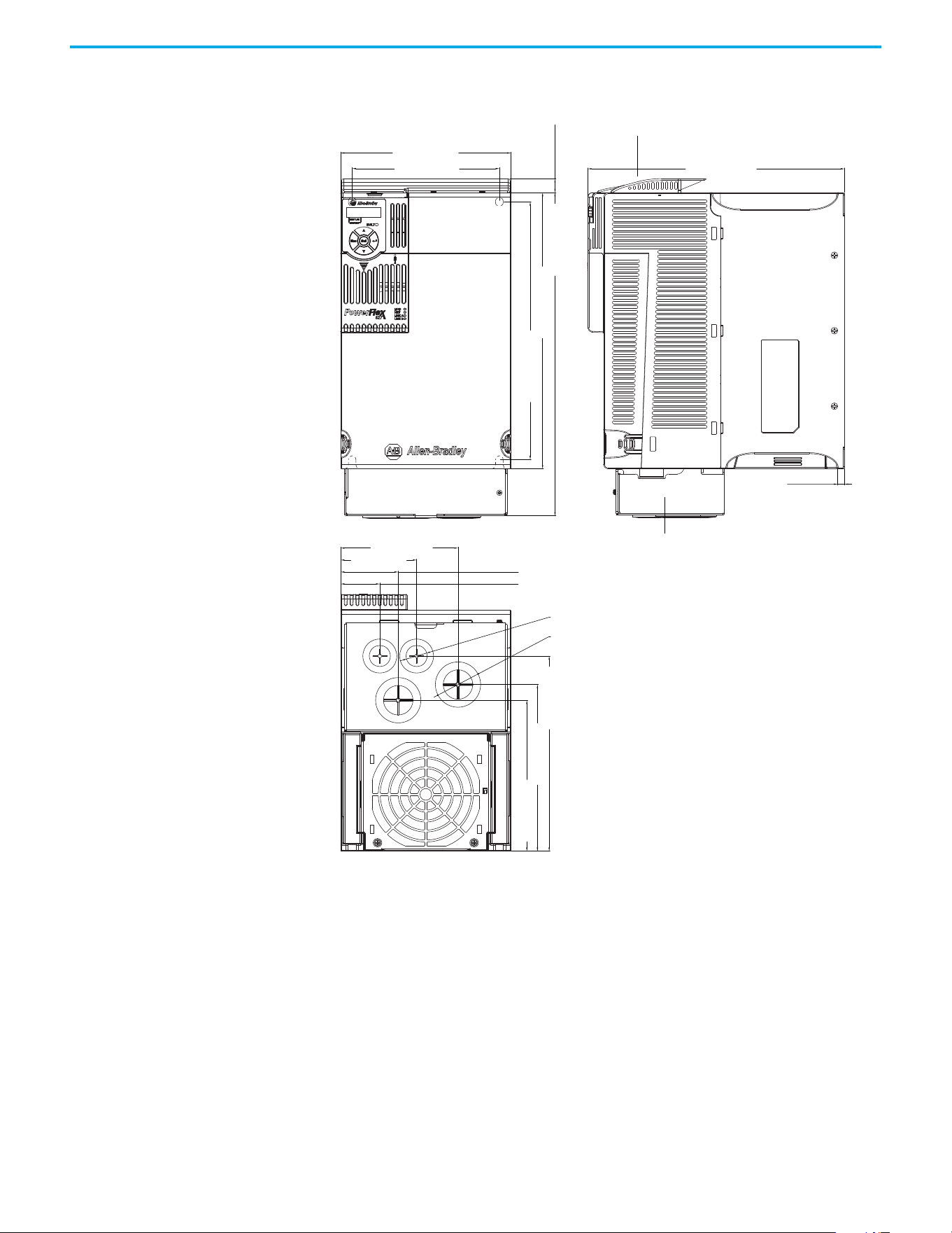
148 Rockwell Automation Publication 520-UM002E-EN-E - September 2024
Appendix B Accessories and Dimensions
IP 30/NEMA 1/UL Type 1 – Frame E
185.0 (7.28)
160.0 (6.30)
127.5 (5.02)
82.5 (3.25)
62.5 (2.46)
42.5 (1.67)
279.0 (10.98)
15.0 (0.59)
350.0 (13.78)
300.0 (11.81)
280.0 (11.02)
212.0 (8.35)
181.0 (7.13)
164.0 (6.46)
7.6 (0.30)
ø21.5 (ø0.85)
ø43.7 (ø1.72)
Dimensions are in millimeters and (inches)
IP 30/NEMA 1/ UL Type 1 conduit box
IP 30/NEMA 1/ UL Type 1 top panel
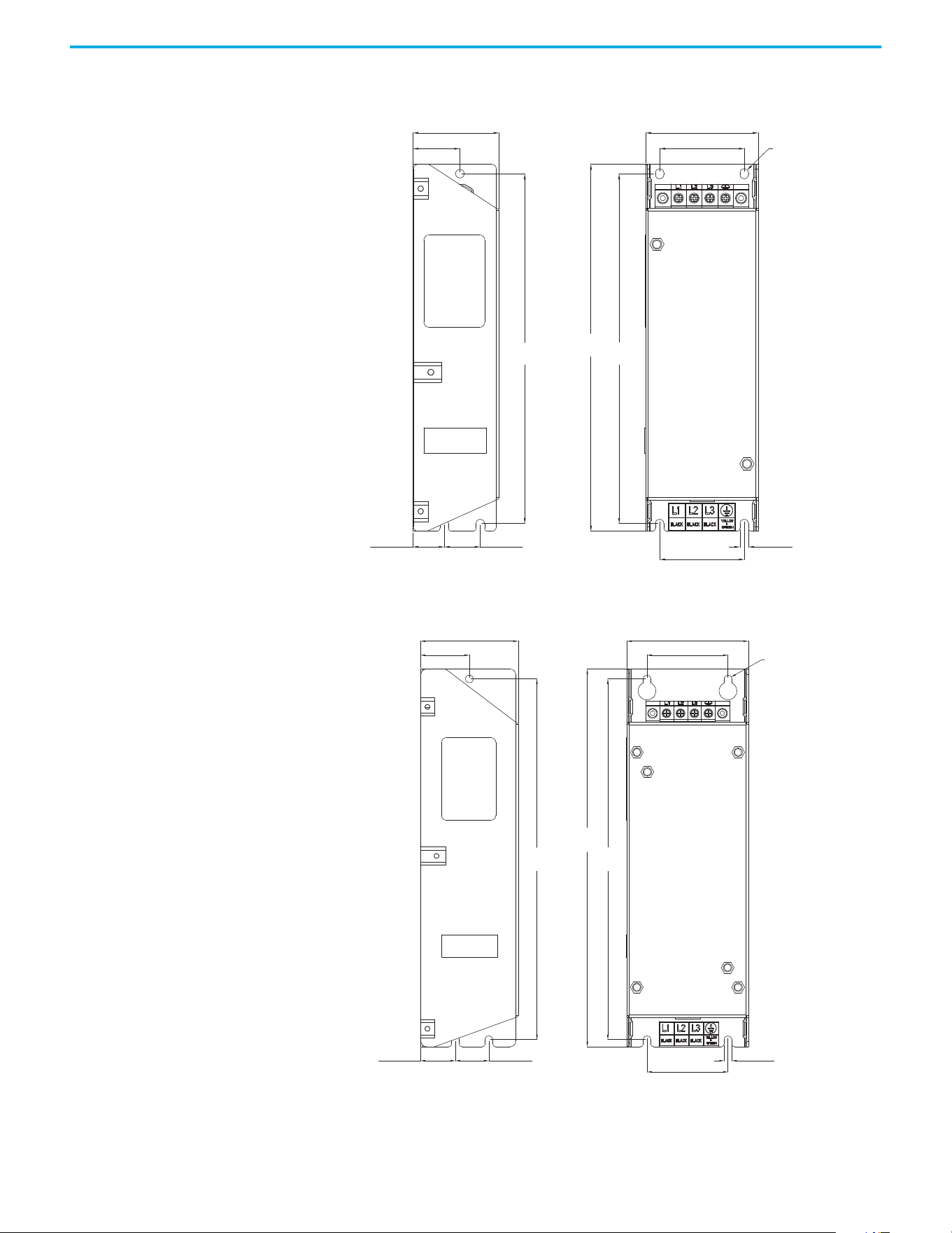
Rockwell Automation Publication 520-UM002E-EN-E - September 2024 149
Appendix B Accessories and Dimensions
EMC Line Filter – Frame A
EMC Line Filter – Frame B
ø5.5 (ø0.22)
72.0 (2.83)
54.0 (2.13)
5.5 (0.22)
54.0 (2.13)
23.0 (0.91)20.0 (0.79)
30.0 (1.18)
55.0 (2.17)
234.0
(9.21)
223.0
(8.78)
223.0
(8.78)
Dimensions are in millimeters and (inches) Filter can be mounted onto the back of the drive.
ø5.5 (ø0.22)
87.0 (3.43)
58.0 (2.28)
270.0
(10.63)
58.0 (2.28)
5.5 (0.22)
258.0
(10.16)
258.0
(10.16)
24.0 (0.94)25.0 (0.98)
35.0 (1.38)
70.0 (2.76)
Dimensions are in millimeters and (inches) Filter can be mounted onto the back of the drive.
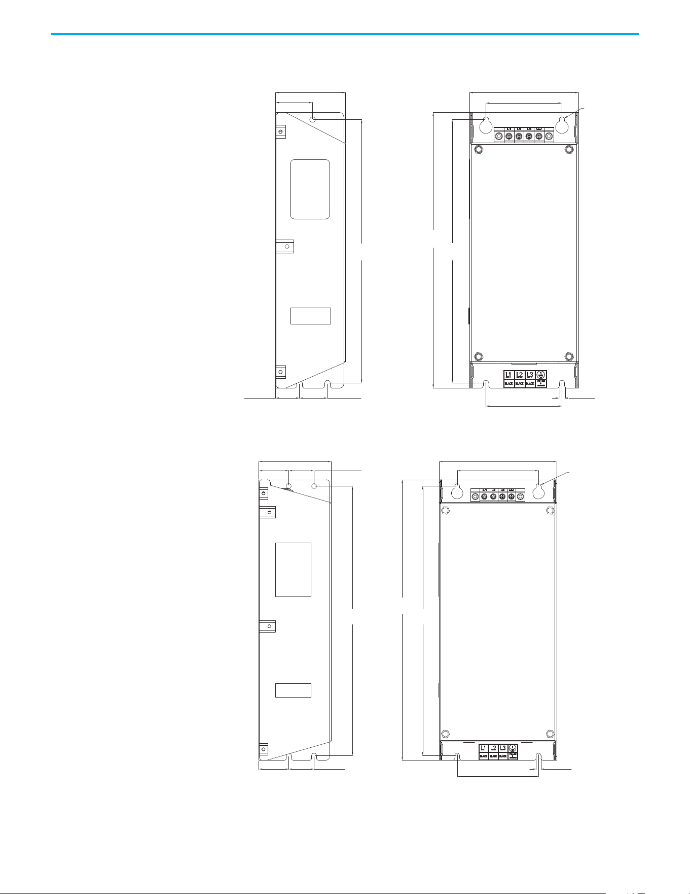
150 Rockwell Automation Publication 520-UM002E-EN-E - September 2024
Appendix B Accessories and Dimensions
EMC Line Filter – Frame C
EMC Line Filter – Frame D
ø5.5 (ø0.22)
263.0
(10.35)
263.0
(10.35)
25.0 (0.98) 28.0 (1.10)
76.0 (2.99)
5.5 (0.22)
275.0
(10.83)
109.0 (4.29)
70.0 (2.76)
76.0 (2.99)
37.0 (1.46)
Dimensions are in millimeters and (inches) Filter can be mounted onto the back of the drive.
ø5.5 (ø0.22)
80.0 (3.15)
130.0 (5.12)
90.0 (3.54)
33.0 (1.30)
33.0 (1.30)
28.0 (1.10)
28.0 (1.10)
298.0
(11.73)
298.0
(11.73)
310.0
(12.20)
90.0 (3.54)
5.5 (0.22)
Dimensions are in millimeters and (inches) Filter can be mounted onto the back of the drive.
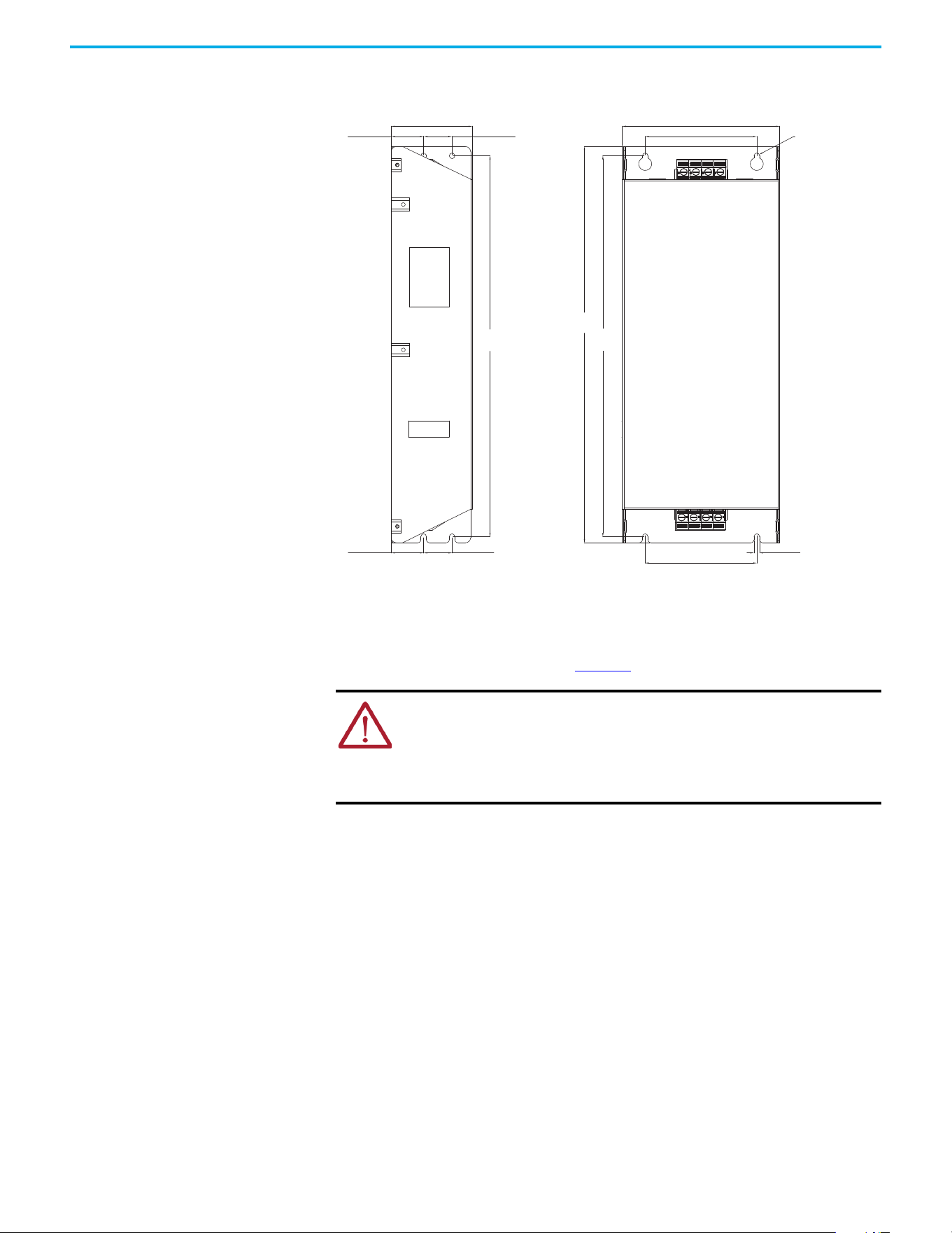
Rockwell Automation Publication 520-UM002E-EN-E - September 2024 151
Appendix B Accessories and Dimensions
EMC Line Filter – Frame E
Replacing the PowerFlex 527 Control Module Internal Fan
To replace the internal fan, you must separate the control module from the power module. Do not
perform this operation while the drive is running. See the PowerFlex 527 Control Module Internal
Fan Kit Installation Instructions, publication 520-IN014
for detailed instructions.
ATTENTION:
• Temperature inside the control module may exceed 80 °C (176 °F) when the
internal fan is not working. Wait for the control module to cool down before
replacing the internal fan.
• Take caution when replacing the internal fan as static damage may occur to
sensitive components inside the drive.
80.0 (3.15)
28.0 (1.10)
155.0 (6.10)
110.0 (4.33)
110.0 (4.33)
33.0 (1.30)
28.0 (1.10)33.0 (1.30)
375.0
(14.76)
375.0
(14.76)
390.0
(15.35)
ø5.5 (ø0.22)
5.5 (0.22)
Dimensions are in millimeters and (inches)

152 Rockwell Automation Publication 520-UM002E-EN-E - September 2024
Appendix B Accessories and Dimensions
Notes:
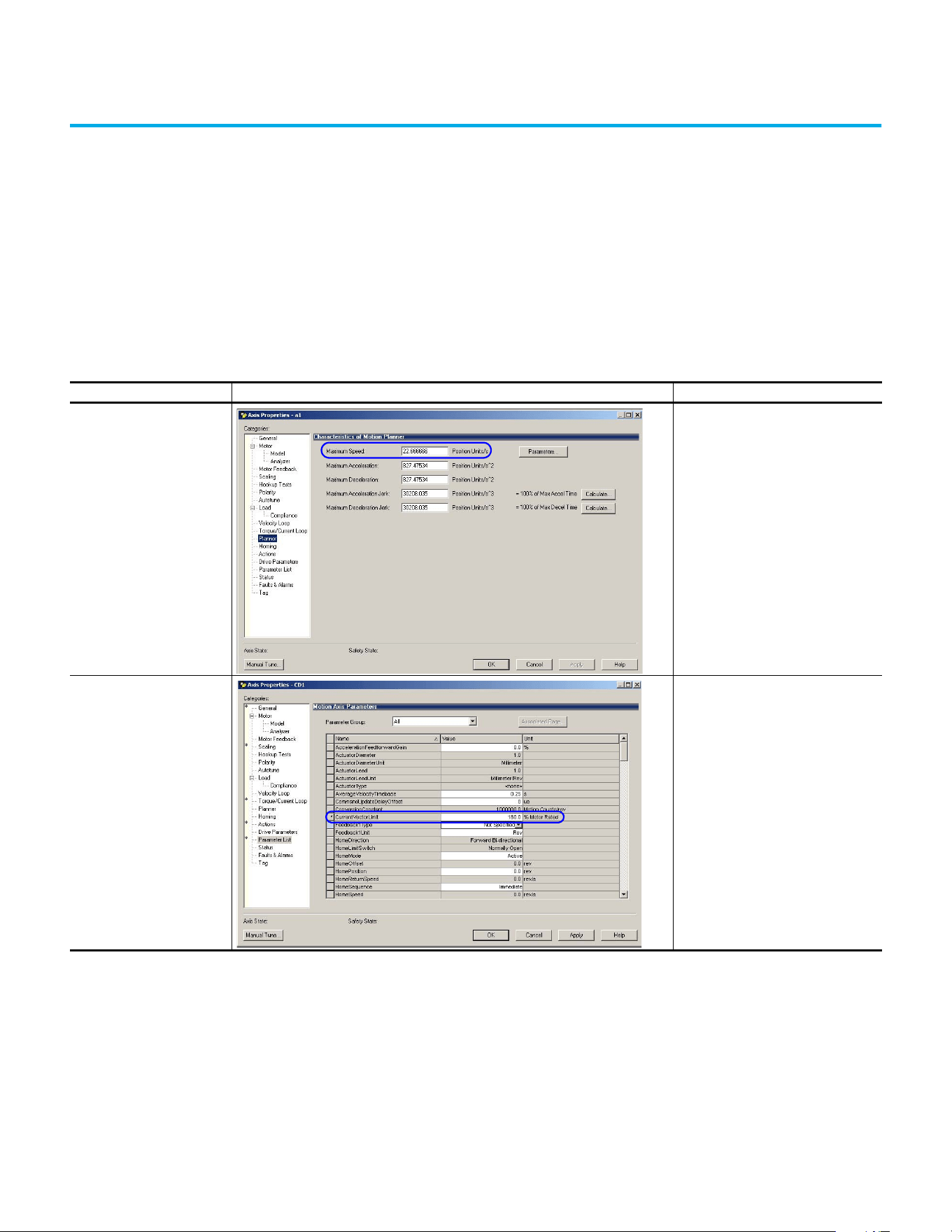
Rockwell Automation Publication 520-UM002E-EN-E - September 2024 153
Appendix
Appendix C
Out-of-Box Configuration
This section describes the recommended settings for configuring your PowerFlex 527 drive to
obtain the best performance from the drive. You should apply these out-of-box settings first before
configuring for your application.
Recommended Out-of-Box
Settings
Out-of-Box Settings
Setting in Logix Designer Example Recommended Configuration
Ramp Velocity Limits
120% of Motor Rated Speed for induction
motors
Current Vector Limit 180% of Motor Rated Current
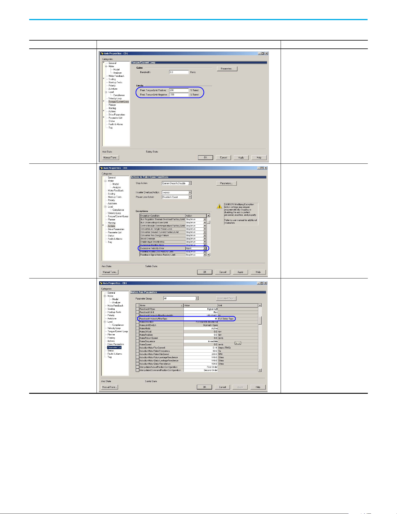
154 Rockwell Automation Publication 520-UM002E-EN-E - September 2024
Appendix C Out-of-Box Configuration
Torque Limits 200% of Motor Rated Torque
Velocity Error Tolerance Change Action to Alarm
Feedback Tap 16
Out-of-Box Settings (Continued)
Setting in Logix Designer Example Recommended Configuration
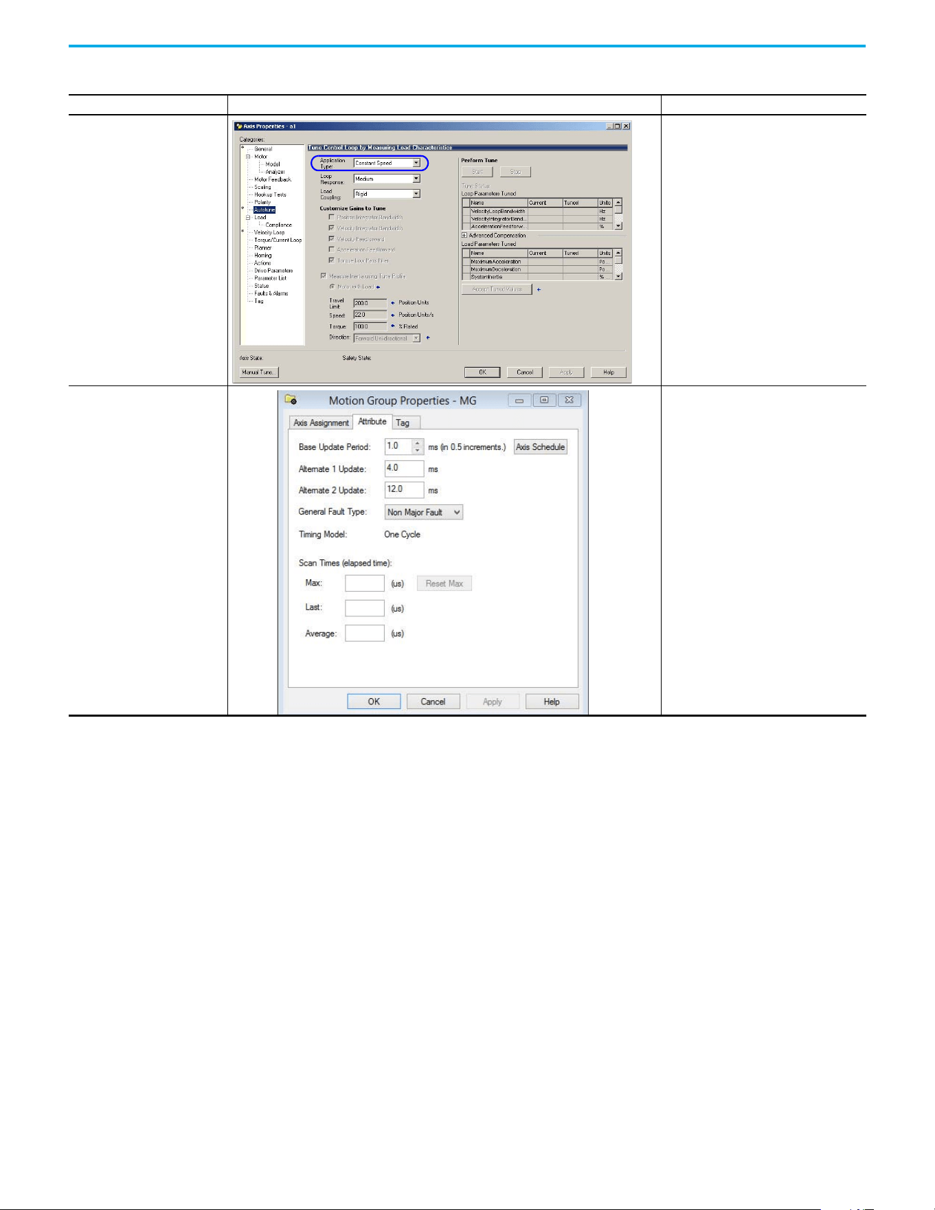
Rockwell Automation Publication 520-UM002E-EN-E - September 2024 155
Appendix C Out-of-Box Configuration
Application Type setting in Velocity
Loop
Constant Speed
Motion Group Base Update Rate 4 ms
Out-of-Box Settings (Continued)
Setting in Logix Designer Example Recommended Configuration
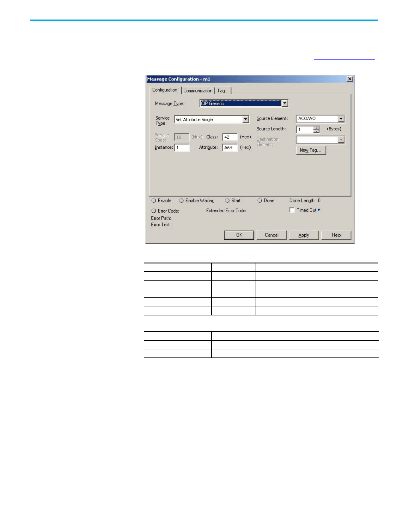
156 Rockwell Automation Publication 520-UM002E-EN-E - September 2024
Appendix C Out-of-Box Configuration
Setting the ACO/AVO
Attribute
The attribute ACO/AVO (Analog Current Output/Analog Voltage Output) can be used to set the analog
output of the PowerFlex 527 drive to either current (mA) or voltage (V).
Verify that the Analog Out jumper (J2) is also set to the same value. See Analog Output on page 35
for instructions.
ACO/AVO: MSG
Parameter Value Description
Service Code 0x10 Set Attribute Single
Class 0x42 Analog Output
Instance 1 –
Attribute 0xA64 Voltage/Current Mode
Data Type SINT Unsigned Short Integer
ACO/AVO: Values
Value Definition
0Voltage (V)
1 Current (mA)
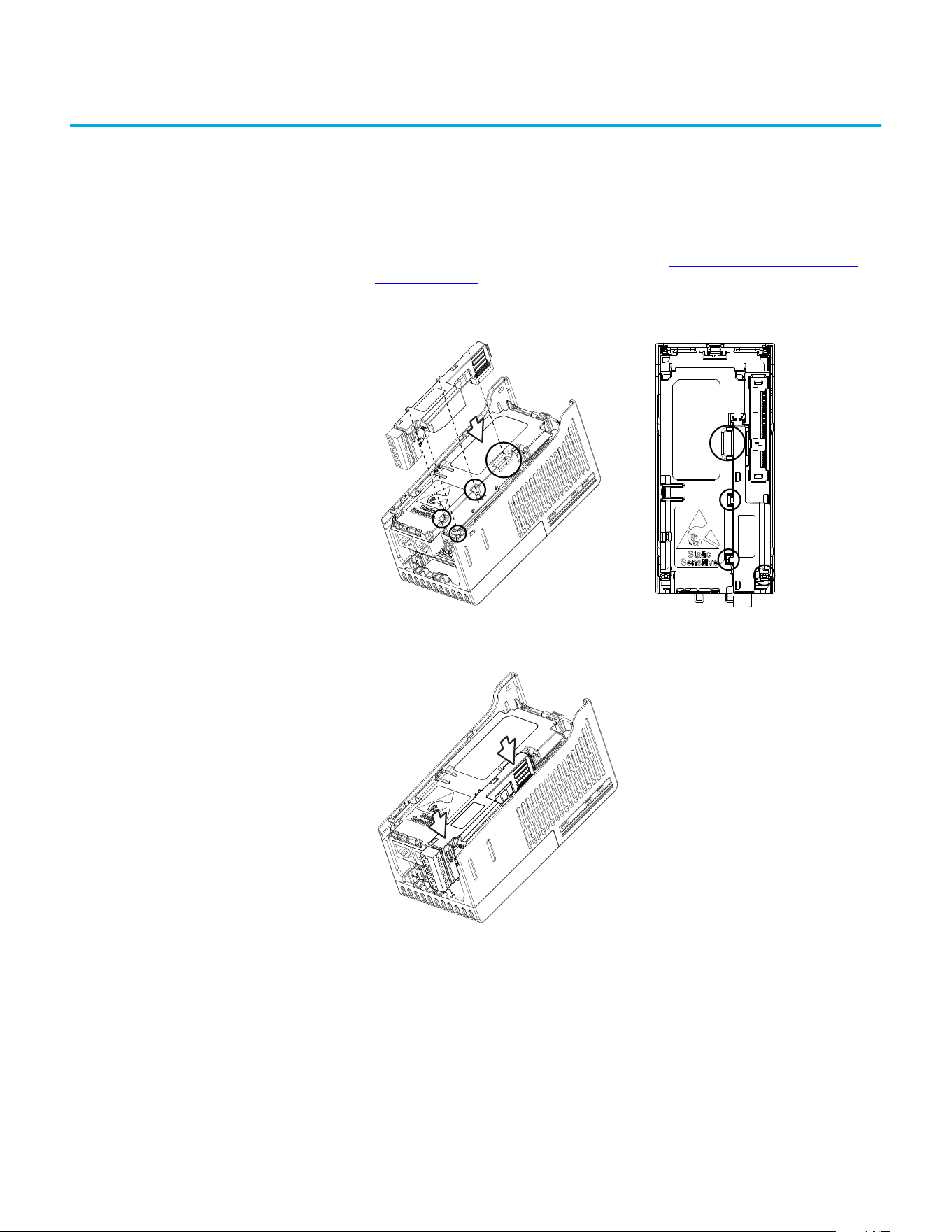
Rockwell Automation Publication 520-UM002E-EN-E - September 2024 157
Appendix
Appendix D
Encoder Option Card Usage
Installing the Encoder
Option Card
To install the encoder option card:
1. Separate the power module and control module. See Separating the Power and Control
Module on page 25 for instructions.
2. Place the encoder option card on the back of the control module. Verify that the tabs on the
encoder option card are aligned with the slots on the control module.
3. Press down firmly on the encoder option card until it snaps together with the control
module.
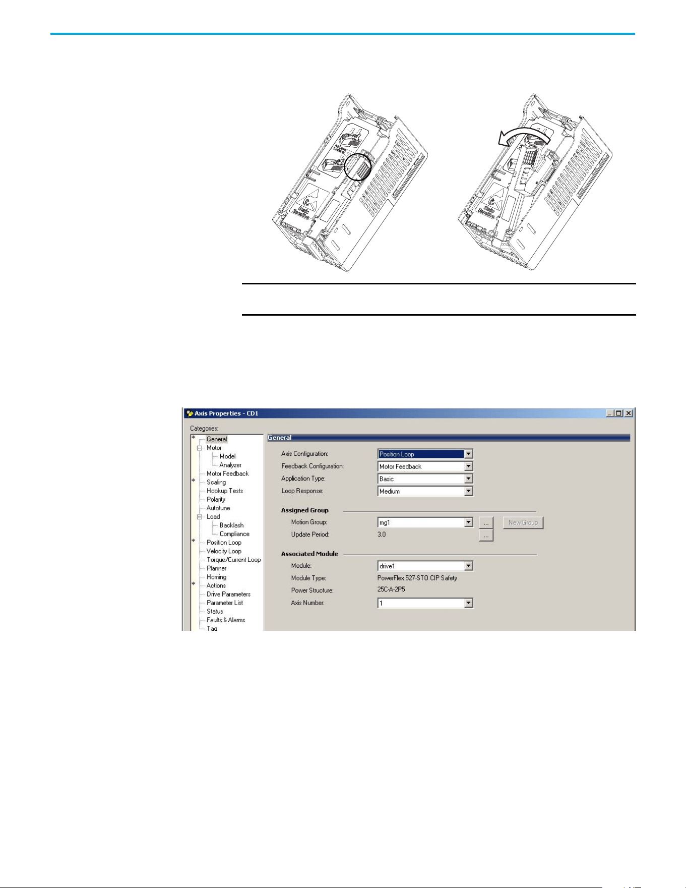
158 Rockwell Automation Publication 520-UM002E-EN-E - September 2024
Appendix D Encoder Option Card Usage
Removing the Encoder
Option Card
To remove the encoder option card:
1. Hold the top of the encoder option card firmly as shown below and pull out to remove.
Encoder Option Card Usage PowerFlex 527 drives support an optional encoder card. The encoder supports up to 250 kHz dual
channel at 5V, 12V, or 24V and requires the optional encoder board to be installed.
When the axis configuration is set to Position or Velocity loop, the Feedback Configuration is
enabled.
IMPORTANT Do not remove the encoder option card from the bottom as it may damage
the card and the locking mechanism on the control module.
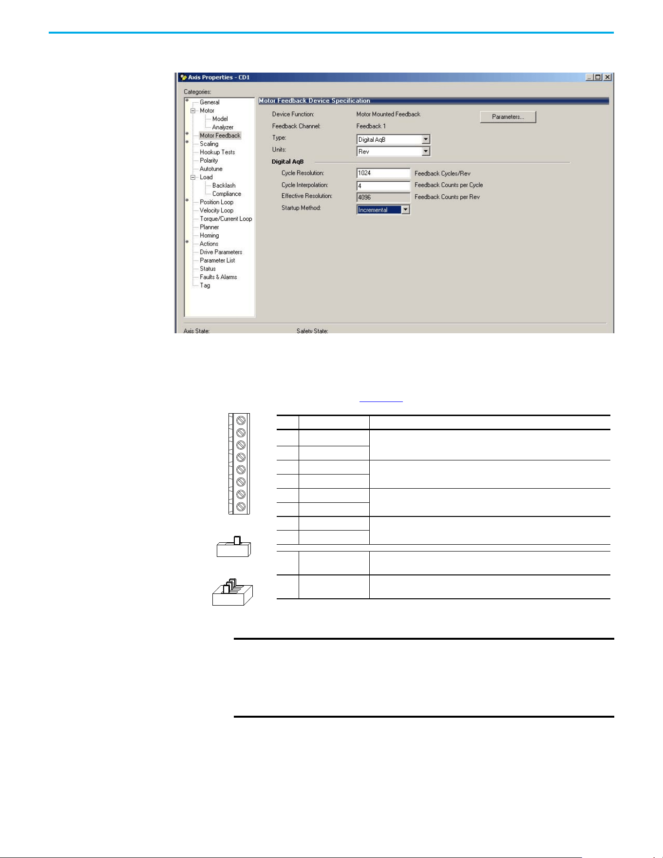
Rockwell Automation Publication 520-UM002E-EN-E - September 2024 159
Appendix D Encoder Option Card Usage
In the Motor Feedback configuration, enter the resolution of the encoder used.
Encoder Interface
The incremental encoder option card can source 5V or 12V power and accept 5V, 12V, or 24V single
ended or differential inputs. See Appendix B for ordering information.
+V
Cm
B-
B
Z-
Z
A-
A
12V 5V
HTL TTL (ON)
No. Signal Description
+V
5...12V Power
(1)(2)
(1) When using 12V Encoder power, 24V I/O power, maximum output current at I/O Terminal 11 is 50 mA.
(2) If Encoder requires 24V power, it must be supplied by an external power source.
Internal power source 250 mA (isolated).
Cm Power Return
Z- Marker Z (NOT)
Marker pulse
ZMarker Z
B- Encoder B (NOT)
Quadrature B input.
BEncoder B
A- Encoder A (NOT)
Quadrature A input.
AEncoder A
Output
DIP switch selects 12V or 5V power that is supplied at terminals “+V” and
“Cm” for the encoder.
HTL/TTL DIP
switches
Set the position of the DIP switches based on the type of encoder signal
used. You must set all switches to the same position.
IMPORTANT A quadrature encoder provides rotor speed and direction. Therefore, the
encoder must be wired such that the forward direction matches the motor
forward direction. If the drive is reading encoder speed but the position
regulator or other encoder function is not working properly, remove power
to the drive and swap the A and A (NOT) encoder channels or swap any two
motor leads.
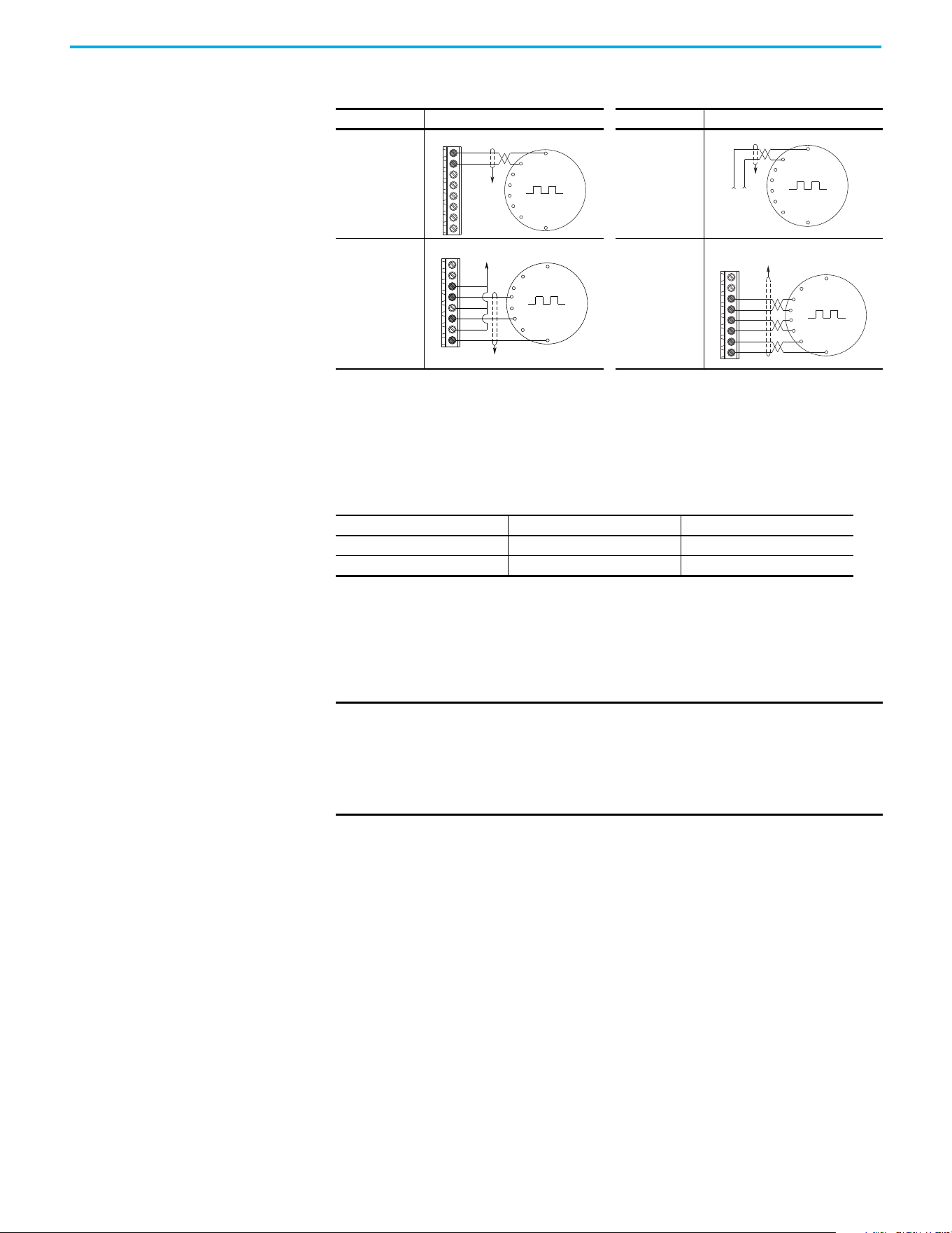
160 Rockwell Automation Publication 520-UM002E-EN-E - September 2024
Appendix D Encoder Option Card Usage
HTL/TTL DIP Switches
This feature is only available on 25-ENC-2/B encoders. Set the three switches to HTL (default) or
TTL (On) based on the type of encoder signal you are using in your application. You must set all
switches to the same position.
Wiring Notes The encoder option card can supply 5V or 12V power (250 mA maximum) for an encoder. Verify that
the DIP switch is set properly for the encoder. In general, 12V provides higher noise immunity.
The encoder can handle 5V, 12V, or 24V inputs. The inputs automatically adjust to the voltage
applied and no additional drive adjustment is necessary.
Encoder Wiring Examples
I/O Connection Example I/O Connection Example
Encoder Power
– Internal Drive
Power
Internal (drive)
12V DC, 250 mA
Encoder Power
– External
Power Source
Encoder Signal –
Single-Ended,
Dual Channel
Encoder Signal –
Differential, Dual
Channel
Compatible Encoder Output Voltage
Switch Position Low Level (UL) High Level (UH)
TTL <1.5V >2.5V
HTL <3.5V >5V
Common
+12V DC
(250 mA)
A
A-
B
B-
Z
Z-
Cm
+V
to SHLD
+
Common
External
Power
Supply
to
SHLD
Marker Z
A
B
Marker
Z NOT
to SHLD
to Power Supply
Common
A
A-
B
B-
Z
Z-
Cm
+V
to SHLD
A NOT
B
A
B NOT
Marker
Z NOT
Marker Z
A
A-
B
B-
Z
Z-
Cm
+V
IMPORTANT A quadrature encoder provides rotor speed and direction. Therefore, the
encoder must be wired such that the forward direction matches the motor
forward direction. If the drive is reading encoder speed but the position
regulator or other encoder function is not working properly, remove power
to the drive and swap the A and A (NOT) encoder channels or swap any two
motor leads.

Rockwell Automation Publication 520-UM002E-EN-E - September 2024 161
Index
A
accessing
control terminals
28
power terminals 28
auxiliary contact
drive
31
B
basic operation
drive
43
C
circuit breakers
inputs
19
ratings 19
control terminals
accessing
28
D
derating
temperature
15
dimensions
mounting
13, 139
disconnect
output
31
drive
auxiliary contact
31
basic operation 43
mount
13
programming
48
drive damage
preventing
16
ungrounded distribution systems
16
E
encoder
wiring
160
environment
storage
16
F
fault monitoring
ground
18
fuses
rating
19
G
ground
fault monitoring
18
motor
18
RFI filter
18
safety 18
shielding
18
I
inputs
circuit breakers
19
power 17
M
motor
ground
18
start 31
stop
31
mount
drive
13
mounting
dimensions
13, 139
N
noise immunity
wiring
33
O
output
disconnect
31
P
power
inputs
17
power and control module
separating
25
power terminals
accessing
28
preventing
drive damage
16
programming
drive
48
tools
48
R
rating
fuses
19
ratings
circuit breakers
19
recommended
wiring
32
reflected
wave protection
31
RFI filter
ground
18
S
safety
ground
18
separating
power and control module
25

162 Rockwell Automation Publication 520-UM002E-EN-E - September 2024
Index
shielded
wiring
30
shielding
ground
18
start
motor
31
stop
motor
31
storage
environment
16
T
temperature
derating
15
wiring
29
tools
programming
48
U
unshielded
wiring
30
V
voltage reflections
wiring
31
W
wave protection
reflected
31
wiring
encoder
160
noise immunity
33
recommended 32
shielded
30
temperature
29
unshielded 30
voltage reflections
31

Rockwell Automation Publication 520-UM002E-EN-E - September 2024 163
PowerFlex 527 Adjustable Frequency AC Drive User Manual User Manual
Publication 520-UM002E-EN-E - September 2024
Supersedes Publication 520-UM002D-EN-E - January 2023 Copyright © 2024 Rockwell Automation, Inc. All rights reserved.
Rockwell Automation Support
Use these resources to access support information.
Documentation Feedback
Your comments help us serve your documentation needs better. If you have any suggestions on how to improve our content, complete the
form at rok.auto/docfeedback.
Waste Electrical and Electronic Equipment (WEEE)
Rockwell Automation maintains current product environmental compliance information on its website at rok.auto/pec.
Technical Support Center
Find help with how-to videos, FAQs, chat, user forums, Knowledgebase, and product
notification updates.
rok.auto/support
Local Technical Support Phone Numbers Locate the telephone number for your country. rok.auto/phonesupport
Technical Documentation Center
Quickly access and download technical specifications, installation instructions, and user
manuals.
rok.auto/techdocs
Literature Library Find installation instructions, manuals, brochures, and technical data publications. rok.auto/literature
Product Compatibility and Download Center
(PCDC)
Download firmware, associated files (such as AOP, EDS, and DTM), and access product release
notes.
rok.auto/pcdc
At the end of life, this equipment should be collected separately from any unsorted municipal waste.
Rockwell Otomasyon Ticaret A.Ş. Kar Plaza İş Merkezi E Blok Kat:6 34752, İçerenköy, İstanbul, Tel: +90 (216) 5698400 EEE Yönetmeliğine Uygundur
Allen-Bradley, CompactLogix, ControlLogix, expanding human possibility, FactoryTalk, GuardLogix, Logix 5000, PowerFlex, Rockwell Automation, RSLinx, RSLogix 5000, Studio 5000, Studio 5000
Automation Engineering and Design Environment, Studio 5000 Logix Designer, and TechConnect are trademarks of Rockwell Automation, Inc.
CIP, CIP Motion, CIP Safety, CIP Sync, and EtherNet/IP are trademarks of ODVA, Inc.
Trademarks not belonging to Rockwell Automation are property of their respective companies.
