User Manual
Original Instructions
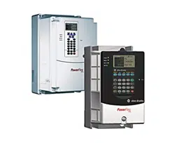
PowerFlex 70 Adjustable Frequency AC Drives
Standard Control Firmware, Revision 2.xxx
Enhanced Control Firmware, Revision 2.xxx…5.xxx
Bulletin Number 20A
Important User Information
Read this document and the documents listed in the additional resources section about installation, configuration, and
operation of this equipment before you install, configure, operate, or maintain this product. Users are required to
familiarize themselves with installation and wiring instructions in addition to requirements of all applicable codes, laws,
and standards.
Activities including installation, adjustments, putting into service, use, assembly, disassembly, and maintenance are required
to be carried out by suitably trained personnel in accordance with applicable code of practice.
If this equipment is used in a manner not specified by the manufacturer, the protection provided by the equipment can be
impaired.
In no event will Rockwell Automation, Inc. be responsible or liable for indirect or consequential damages resulting from the
use or application of this equipment.
The examples and diagrams in this manual are included solely for illustrative purposes. Because of the many variables and
requirements associated with any particular installation, Rockwell Automation, Inc. cannot assume responsibility or
liability for actual use based on the examples and diagrams.
No patent liability is assumed by Rockwell Automation, Inc. with respect to use of information, circuits, equipment, or
software described in this manual.
Reproduction of the contents of this manual, in whole or in part, without written permission of Rockwell Automation,
Inc., is prohibited.
Throughout this manual, when necessary, we use notes to make you aware of safety considerations.
Labels can also be on or inside the equipment to provide specific precautions.
WARNING: Identifies information about practices or circumstances that can cause an explosion in a hazardous environment,
which can lead to personal injury or death, property damage, or economic loss.
ATTENTION: Identifies information about practices or circumstances that can lead to personal injury or death, property
damage, or economic loss. Attentions help you identify a hazard, avoid a hazard, and recognize the consequence.
IMPORTANT
Identifies information that is critical for successful application and understanding of the product.
SHOCK HAZARD: Labels can be on or inside the equipment, for example, a drive or motor, to alert people that dangerous
voltage can be present.
BURN HAZARD: Labels can be on or inside the equipment, for example, a drive or motor, to alert people that surfaces can
reach dangerous temperatures.
ARC FLASH HAZARD: Labels can be on or inside the equipment, for example, a motor control center, to alert people to
potential Arc Flash. Arc Flash will cause severe injury or death. Wear proper Personal Protective Equipment (PPE). Follow ALL
Regulatory requirements for safe work practices and for Personal Protective Equipment (PPE).

Rockwell Automation Publication 20A-UM001P-EN-P - February 2018 3
Table of Contents
Preface
About This Publication. . . . . . . . . . . . . . . . . . . . . . . . . . . . . . . . . . . . . . . . . . . . . 5
What Is Not in This Publication . . . . . . . . . . . . . . . . . . . . . . . . . . . . . . . . . . . . 5
Summary of Changes . . . . . . . . . . . . . . . . . . . . . . . . . . . . . . . . . . . . . . . . . . . . . . . 5
Additional Resources . . . . . . . . . . . . . . . . . . . . . . . . . . . . . . . . . . . . . . . . . . . . . . . 6
Manual Conventions . . . . . . . . . . . . . . . . . . . . . . . . . . . . . . . . . . . . . . . . . . . . . . . 7
Drive Frame Sizes . . . . . . . . . . . . . . . . . . . . . . . . . . . . . . . . . . . . . . . . . . . . . . . . . . 7
General Precautions . . . . . . . . . . . . . . . . . . . . . . . . . . . . . . . . . . . . . . . . . . . . . . . . 8
Qualified Personnel . . . . . . . . . . . . . . . . . . . . . . . . . . . . . . . . . . . . . . . . . . . . 8
Personal Safety . . . . . . . . . . . . . . . . . . . . . . . . . . . . . . . . . . . . . . . . . . . . . . . . . 8
Product Safety . . . . . . . . . . . . . . . . . . . . . . . . . . . . . . . . . . . . . . . . . . . . . . . . . 8
Output Contactor Precaution . . . . . . . . . . . . . . . . . . . . . . . . . . . . . . . . . . . 9
Catalog Number Explanation . . . . . . . . . . . . . . . . . . . . . . . . . . . . . . . . . . . . . 10
Chapter 1
Programming and Parameters
About Parameters . . . . . . . . . . . . . . . . . . . . . . . . . . . . . . . . . . . . . . . . . . . . . . . . 11
How Parameters Are Organized. . . . . . . . . . . . . . . . . . . . . . . . . . . . . . . . . . . 13
LED HIM (Human Interface Module). . . . . . . . . . . . . . . . . . . . . . . . . 13
LCD HIM (Human Interface Module) . . . . . . . . . . . . . . . . . . . . . . . . 14
Basic Parameter View – Standard Control . . . . . . . . . . . . . . . . . . . . . . 15
Basic Parameter View – Enhanced Control . . . . . . . . . . . . . . . . . . . . . 16
Advanced Parameter View – Standard Control . . . . . . . . . . . . . . . . . 17
Advanced Parameter View – Enhanced Control . . . . . . . . . . . . . . . . 19
Monitor File (File A) . . . . . . . . . . . . . . . . . . . . . . . . . . . . . . . . . . . . . . . . . . . . . 21
Motor Control File (File B) . . . . . . . . . . . . . . . . . . . . . . . . . . . . . . . . . . . . . . . 23
Speed Command File (File C). . . . . . . . . . . . . . . . . . . . . . . . . . . . . . . . . . . . . 30
Dynamic Control File (File D) . . . . . . . . . . . . . . . . . . . . . . . . . . . . . . . . . . . . 40
Utility File (File E) . . . . . . . . . . . . . . . . . . . . . . . . . . . . . . . . . . . . . . . . . . . . . . . 48
Communication File (File H) . . . . . . . . . . . . . . . . . . . . . . . . . . . . . . . . . . . . . 59
Inputs and Outputs File
(File J) . . . . . . . . . . . . . . . . . . . . . . . . . . . . . . . . . . . . . . . . . . . . . . . . . . . . . . . . . . 64
Selected Option Definitions – [Analog Outx Sel], [Digital Inx Sel],
and [Digital Outx Sel] . . . . . . . . . . . . . . . . . . . . . . . . . . . . . . . . . . . . . . . . 70
Applications File (File K) . . . . . . . . . . . . . . . . . . . . . . . . . . . . . . . . . . . . . . . . . 71
Parameter Cross Reference – by Name . . . . . . . . . . . . . . . . . . . . . . . . . . . . . 72
Chapter 2
Troubleshooting
Faults and Alarms . . . . . . . . . . . . . . . . . . . . . . . . . . . . . . . . . . . . . . . . . . . . . . . . 77
Drive Status . . . . . . . . . . . . . . . . . . . . . . . . . . . . . . . . . . . . . . . . . . . . . . . . . . . . . 77
HIM Indication. . . . . . . . . . . . . . . . . . . . . . . . . . . . . . . . . . . . . . . . . . . . . . 78
Manually Clearing Faults . . . . . . . . . . . . . . . . . . . . . . . . . . . . . . . . . . . . . 78
Fault Descriptions. . . . . . . . . . . . . . . . . . . . . . . . . . . . . . . . . . . . . . . . . . . . 79
Clearing Alarms. . . . . . . . . . . . . . . . . . . . . . . . . . . . . . . . . . . . . . . . . . . . . . . . . . 82
Alarm Descriptions. . . . . . . . . . . . . . . . . . . . . . . . . . . . . . . . . . . . . . . . . . . 83

4 Rockwell Automation Publication 20A-UM001P-EN-P - February 2018
Table of Contents
Testpoint Codes and Functions . . . . . . . . . . . . . . . . . . . . . . . . . . . . . . . . . . . 85
Common Symptoms and Corrective Actions . . . . . . . . . . . . . . . . . . . . . . . 86
Appendix A
Supplemental Drive Information
Communication Configurations. . . . . . . . . . . . . . . . . . . . . . . . . . . . . . . . . . . 89
Typical Programmable Controller Configurations. . . . . . . . . . . . . . . 89
Logic Command Word/ Logic Status Word . . . . . . . . . . . . . . . . . . . . 90
Output Devices . . . . . . . . . . . . . . . . . . . . . . . . . . . . . . . . . . . . . . . . . . . . . . . . . . 91
Appendix B
HIM Overview
External and Internal Connections . . . . . . . . . . . . . . . . . . . . . . . . . . . . . . . . 93
Using the HIM with a 20-HIM-B1 Bezel Kit . . . . . . . . . . . . . . . . . . . 94
LCD Display Elements . . . . . . . . . . . . . . . . . . . . . . . . . . . . . . . . . . . . . . . . . . . 95
ALT Functions. . . . . . . . . . . . . . . . . . . . . . . . . . . . . . . . . . . . . . . . . . . . . . . . . . . 95
Removing the HIM. . . . . . . . . . . . . . . . . . . . . . . . . . . . . . . . . . . . . . . . . . . . . . . 95
Menu Structure . . . . . . . . . . . . . . . . . . . . . . . . . . . . . . . . . . . . . . . . . . . . . . . . . . 96
Viewing and Editing Parameters . . . . . . . . . . . . . . . . . . . . . . . . . . . . . . . . . . . 97
LCD HIM . . . . . . . . . . . . . . . . . . . . . . . . . . . . . . . . . . . . . . . . . . . . . . . . . . . 98
Numeric Keypad Shortcut. . . . . . . . . . . . . . . . . . . . . . . . . . . . . . . . . . . . . 98
Appendix C
Application Notes
External Brake Resistor . . . . . . . . . . . . . . . . . . . . . . . . . . . . . . . . . . . . . . . . . . 100
Skip Frequency. . . . . . . . . . . . . . . . . . . . . . . . . . . . . . . . . . . . . . . . . . . . . . . . . . 101
Stop Modes . . . . . . . . . . . . . . . . . . . . . . . . . . . . . . . . . . . . . . . . . . . . . . . . . . . . . 103
Configuration . . . . . . . . . . . . . . . . . . . . . . . . . . . . . . . . . . . . . . . . . . . . . . . 104
Detailed Operation . . . . . . . . . . . . . . . . . . . . . . . . . . . . . . . . . . . . . . . . . . 105
Motor Overload. . . . . . . . . . . . . . . . . . . . . . . . . . . . . . . . . . . . . . . . . . . . . . . . . 107
Motor Overload Memory Retention Per 2005 NEC. . . . . . . . . . . . . . . . 109
Start at Powerup . . . . . . . . . . . . . . . . . . . . . . . . . . . . . . . . . . . . . . . . . . . . . . . . 109
Overspeed . . . . . . . . . . . . . . . . . . . . . . . . . . . . . . . . . . . . . . . . . . . . . . . . . . . . . . 109
Speed Reference Control. . . . . . . . . . . . . . . . . . . . . . . . . . . . . . . . . . . . . . . . . 110
“Auto” Speed Sources . . . . . . . . . . . . . . . . . . . . . . . . . . . . . . . . . . . . . . . . 110
“Manual” Speed Sources. . . . . . . . . . . . . . . . . . . . . . . . . . . . . . . . . . . . . . 111
Changing Speed Sources . . . . . . . . . . . . . . . . . . . . . . . . . . . . . . . . . . . . . 111
Auto/Manual Examples. . . . . . . . . . . . . . . . . . . . . . . . . . . . . . . . . . . . . . . . . . 112
PLC = Auto, HIM = Manual. . . . . . . . . . . . . . . . . . . . . . . . . . . . . . . . . 112
PLC = Auto, Terminal Block = Manual . . . . . . . . . . . . . . . . . . . . . . . 112
Auto/Manual Notes . . . . . . . . . . . . . . . . . . . . . . . . . . . . . . . . . . . . . . . . . 112
Process PI for Standard Control . . . . . . . . . . . . . . . . . . . . . . . . . . . . . . . . . . 113
PI Enable . . . . . . . . . . . . . . . . . . . . . . . . . . . . . . . . . . . . . . . . . . . . . . . . . . . 113
Voltage Tolerance . . . . . . . . . . . . . . . . . . . . . . . . . . . . . . . . . . . . . . . . . . . . . . . 115
Rockwell Automation Publication 20A-UM001P-EN-P - February 2018 5
Preface
The purpose of this manual is to provide you with the basic information that is
needed to program and troubleshoot the PowerFlex 70 Adjustable Frequency AC
Drive.
About This Publication
This manual is intended for qualified personnel. You must be able to program
and operate Adjustable Frequency AC Drive devices. In addition, you must have
an understanding of the parameter settings and functions.
What Is Not in This
Publication
This manual provides basic start-up, programming, and troubleshooting
information; it excludes information for mounting, wiring, and installing the
drive. For installation instructions, refer to the PowerFlex 70 Adjustable
Frequency AC Drive Installation Instructions, publication 20A-IN009
. For
detailed drive information, refer to the PowerFlex Reference Manuals,
publications PFLEX-RM001
and PFLEX-RM004.
Summary of Changes
The information below summarizes the changes to this PowerFlex® 70 Adjustable
Frequency AC Drives User Manual since the July 2014 release. The following
information has been added, removed, or updated.
Topic Page
About This Publication 5
What Is Not in This Publication 5
Additional Resources 6
Manual Conventions 7
Drive Frame Sizes 7
General Precautions 8
Catalog Number Explanation 10
Description of New or Updated Information Page
Removed information about Output Phase Loss - Fault 21. All
Added Original Instructions to the cover and updated the firmware revision number. Front Cover
Updated the Catalog Number Explanation to the current standards (made symbols
footnotes).
10
Update and added footnotes to catalog variables c5 and l. 10
Updated bit table for parameter 238: Fault Config 1. 57
Added parameter 549: Flux Braking % 59
Changed Value 60 Manual/Auto to Value 68 Manual/Auto for parameters 361…366 67

6 Rockwell Automation Publication 20A-UM001P-EN-P - February 2018
Preface
Additional Resources
These documents contain additional information concerning related products
from Rockwell Automation.
You can view or download publications at
http://www.rockwellautomation.com/literature/
. To order paper copies of
technical documentation, contact your local Allen-Bradley distributor or
Rockwell Automation sales representative.
For Allen-Bradley® drives technical support, see Rockwell Automation Support
on the back cover of this manual.
Resource Description
PowerFlex 70 Adjustable Frequency AC Drive Installation
Instructions, publication 20A-IN009
Provides the five basic steps that are needed to install
and perform a basic startup of the PowerFlex 70 drive.
PowerFlex 70 and 700 Reference Manual - Vol. 1,
publication PFLEX-RM001
Provides detailed information for specifications and
dimensions, operation, and dynamic brake selection for
the drive.
PowerFlex 70 Enhanced Control and 700 Vector Control
Reference Manual, publication PFLEX-RM004
Provides detailed drive information including
operation, parameter descriptions, and programming.
DriveGuard Safe-Off Option (Series B) for PowerFlex 40P and
PowerFlex 70 AC Drives, publication PFLEX-UM003
Provides information for the installation and operation
of the DriveGuard Safe Torque Off option.
PowerFlex Comm Adapter Manuals, publication
20COMM-UM…
Provides information for the installation and operation
of the various communication protocol adapters
available for the drive.
PowerFlex Dynamic Braking Resistor Calculator Application
Technique, publication PFLEX-AT001
Provided information for determining dynamic braking
requirements and evaluating resistors for dynamic
braking.
Wiring and Grounding Guidelines for Pulse Width Modulated
(PWM) AC Drives, publication DRIVES-IN001
Provides the basic information that is needed to
properly wire and ground Pulse Width Modulated
(PWM) AC drives.
Industry Installation Guidelines for Pulse Width Modulated
(PWM) AC Drives Application Technique,
publication DRIVES-AT003
Provides basic information for enclosure systems and
environmental/location considerations (to help protect
against environmental contaminants), and power and
grounding considerations that are needed to properly
install AC drives.
Preventive Maintenance of Industrial Control and Drive
System Equipment, publication DRIVES-TD001
Provides a checklist to use as a guide for performing
preventive maintenance on industrial control and drive
systems.
Safety Guidelines for the Application, Installation, and
Maintenance of Solid State Controls, publication SGI-1.1
Describes some important differences between
solid-state equipment and hard-wired
electromechanical devices
Guarding Against Electrostatic Damage,
publication 8000-4.5.2
This data sheet explains the causes of electrostatic
damage (ESD), and how you can guard against its
effects.
Industrial Automation Wiring and Grounding Guidelines,
publication 1770-4.1
Provides general guidelines for installing a Rockwell
Automation industrial system.
Product Certifications website,
http://ab.rockwellautomation.com
Provides declarations of conformity, certificates, and
other certification details.

Rockwell Automation Publication 20A-UM001P-EN-P - February 2018 7
Preface
Manual Conventions
In this manual we refer to the PowerFlex 70 Adjustable Frequency AC Drive as;
drive, PowerFlex 70, or PowerFlex 70 Drive.
To help differentiate parameter names and Liquid Crystal Display (LCD) text
from other text, the following conventions are used:
• Parameter Names appear in [brackets].
For example: [DC Bus Voltage].
• Display Text appears in “quotes.” For example: “Enabled.”
Drive Frame Sizes
Similar PowerFlex 70 drive sizes are grouped into frame sizes to simplify spare
parts ordering, dimensioning, and so on. A cross reference of drive catalog
numbers and their respective frame size is provided in Appendix
A.

8 Rockwell Automation Publication 20A-UM001P-EN-P - February 2018
Preface
General Precautions
Qualified Personnel
Personal Safety
Product Safety
ATTENTION: Allow only qualified personnel familiar with adjustable frequency
AC drives and associated machinery to plan or implement the installation,
start-up and subsequent maintenance of the system. Failure to comply can
result in personal injury and/or equipment damage.
ATTENTION: To avoid an electric shock hazard, verify that the voltage on the
bus capacitors has discharged before performing any work on the drive.
Measure the DC bus voltage at the +DC terminal of the Power Terminal Block
and the -DC test point (refer to PowerFlex 70 Adjustable Frequency AC Drive
Installation Instructions, publication 20A-IN009
for locations). The voltage must
be zero.
ATTENTION: Risk of injury or equipment damage exists. DPI or SCANport host
products must not be directly connected together via 1202 cables.
Unpredictable behavior can result if two or more devices are connected in this
manner.
ATTENTION: The drive start/stop/enable control circuitry includes solid state
components. If hazards due to accidental contact with moving machinery or
unintentional flow of liquid, gas, or solids exist, an additional hardwired stop
circuit may be required to remove the AC line to the drive. An auxiliary braking
method may be required.
ATTENTION: An incorrectly applied or installed drive can result in component
damage or a reduction in product life. Wiring or application errors, such as,
undersizing the motor, incorrect or inadequate AC supply, or excessive ambient
temperatures can result in malfunction of the system.
ATTENTION: This drive contains ESD (Electrostatic Discharge) sensitive parts and
assemblies. Static control precautions are required when installing, testing,
servicing or repairing this assembly. Component damage can result if ESD
control procedures are not followed. If you are not familiar with static control
procedures, reference A-B publication 8000-4.5.2
, “Guarding Against
Electrostatic Damage” or any other applicable ESD protection handbook.
ATTENTION: Configuring an analog input for 0…20 mA operation and driving
it from a voltage source could cause component damage. Verify proper
configuration before applying input signals.
ATTENTION: A contactor or other device that routinely disconnects and
reapplies the AC line to the drive to start and stop the motor can cause drive
hardware damage. The drive is designed to use control input signals to start and
stop the motor. If an input device is used, operation must not exceed one cycle
per minute or drive damage can occur.

Rockwell Automation Publication 20A-UM001P-EN-P - February 2018 9
Preface
Output Contactor Precaution
ATTENTION: Nuisance tripping can occur in Standard Control firmware revision
1.011 and earlier due to unstable currents. When using a motor that is
connected for a voltage that differs from the drive (for example, by using a 230V
connected motor with a 460V drive) the following adjustment must be made to
“Stability Gain” by using DriveExplorer software and a personal computer.
Any adjustment that is made to “Stability Gain” must be manually restored if the
drive is reset to defaults or is replaced.
If unstable currents are still present after making the adjustment, contact the
factory for assistance.
ATTENTION: The “adjust freq” portion of the bus regulator function is useful for
preventing nuisance overvoltage faults resulting from aggressive decelerations,
overhauling loads, and eccentric loads. It forces the output frequency to be
greater than commanded frequency while the drive’s bus voltage is increasing
towards levels that can cause a fault; however, it can also cause either of the
following two conditions to occur.
• Fast positive changes in input voltage (more than a 10% increase within 6
minutes) can cause uncommanded positive speed changes; however an F25
“OverSpeed Limit” fault occurs if the speed reaches P82 [Max Speed] + P83
[Overspeed Limit]. If this condition is unacceptable, take action to: 1) limit
supply voltages within the specification of the drive and, 2) limit fast positive
input voltage changes to less than 10%. Without taking such actions, if this
operation is unacceptable, the “adjust freq” portion of the bus regulator
function must be disabled (see parameters 161 [Bus Reg Mode A] and 162 [Bus
Reg Mode B]).
• Actual deceleration times can be longer than commanded deceleration times;
however, a “Decel Inhibit” fault is generated if the drive stops decelerating
altogether. If this condition is unacceptable, the “adjust freq” portion of the bus
regulator must be disabled (see parameters 161 [Bus Reg Mode A] and 162 [Bus
Reg Mode B]). In addition, installing a properly sized dynamic brake resistor
provides equal or better performance in most cases.
Note: These faults are not instantaneous and have shown test results that take
2...12 seconds to occur.
ATTENTION: To guard against drive damage when using output contactors, the
following information must be read and understood. One or more output
contactors can be installed between the drive and motor for disconnecting or
isolating certain motors/loads. If a contactor is opened while the drive is
operating, power is removed from the respective motor, but the drive continues
to produce voltage at the output terminals. In addition, reconnecting a motor to
an active drive (by closing the contactor) could produce excessive current that
can cause the drive to fault. If any of these conditions are determined to be
undesirable or unsafe, wire an auxiliary contact on the output contactor to a
drive digital input that is programmed as “Enable.” This causes the drive to
execute a coast-to-stop (cease output) whenever an output contactor is opened.
Motor Nameplate Voltage
Drive Rated Voltage
---------------------------------------------------------------
128
10 Rockwell Automation Publication 20A-UM001P-EN-P - February 2018
Preface
Catalog Number Explanation
a
b
c1
c2
h
j
c3
c4
i
k
c5
d
e
f
g
l
Drive
Code Type
20 A PowerFlex 70
Voltage Rating
Code Voltage Ph.
B240V AC3 (6 pulse)
C400V AC3 (6 pulse)
D480V AC3 (6 pulse)
E600V AC3 (6 pulse)
PowerFlex 70 ND Rating
208V, 60 Hz Input
Code 208V Amps kW Hp Frame
2P2 2.5 0.37 0.5
A
4P2 4.8 0.75 1.0
6P8 7.8 1.5 2.0
B
9P6 11 2.2 3.0
015 17.5 4.0 5.0 C
022 25.3 5.5 7.5
D
028 32.2 7.5 10
042 43 11 15
054 56 15 20
E
070 78.2 18.5 25
PowerFlex 70 ND Rating
240V, 60 Hz Input
Code Amps kW Hp Frame
2P2 2.2 0.37 0.5
A
4P2 4.2 0.75 1.0
6P8 6.8 1.5 2.0
B
9P6 9.6 2.2 3.0
015 15.3 4.0 5.0 C
022 22 5.5 7.5
D
028 28 7.5 10
042 42 11 15
054 54 15 20
E
0707018.525
Internal Brake Resistor
Code w/ Resistor
YYes
NNo
Comm Slot
Code Network Type
C ControlNet (Coax)
D DeviceNet
E EtherNet/IP
NNone
PowerFlex 70 ND Rating
400V, 50 Hz Input
Code Amps kW Hp Frame
1P3 1.3 0.37 0.5
A
2P1 2.1 0.75 1.0
3P5 3.5 1.5 2.0
5P0 5.0 2.2 3.0
B
8P7 8.7 4.0 5.0
011 11.5 5.5 7.5
C
015 15.4 7.5 10
022 22 11 15
D
030 30 15 20
037 37 18.5 25
043 42 22 30
060 60 30 40
E
072 72 37 50
PowerFlex 70 ND Rating
480V, 50 Hz Input
Code Amps kW Hp Frame
1P1 1.1 0.37 0.5
A
2P1 2.1 0.75 1.0
3P4 3.4 1.5 2.0
5P0 5.0 2.2 3.0
B
8P0 8.0 3.7 5.0
011 11 5.5 7.5
C
014 14 7.5 10
022221115
D
027271520
034 34 18.5 25
040402230
052523040
E
065653750
Emission Class
Code Rating
A
Filtered
(1)
A
(2)
& B Frames (Optional)
C, D, & E Frames (Standard)
(1) 600V Frames A…D available only without filter (Cat. Code
N). 600V Frame E available with filter (Cat. Code A).
(2) Increases size to Frame B.
N
Not Filtered
(1)
A & B Frames (Optional)
C, D, & E Frames (Standard)
Control and I/O
Code Control Safe-Off
N
(1)
(1) No longer available for sale.
Standard N/A
C Enhanced No
G
(2)
(2) Not available as a factory installed option for 600V ratings.
Enhanced Yes
PowerFlex 70 ND Rating
600V, 60 Hz Input
(1)
(1) 600V class drives below 52 Amps (Frames A-E) are declared
to meet the Low Voltage Directive. It is the responsibility of
the user to determine compliance to the EMC directive.
Code Amps kW Hp Frame
0P9 0.9 0.37 0.5
A
1P7 1.7 0.75 1.0
2P7 2.7 1.5 2.0
3P9 3.9 2.2 3.0
B
6P1 6.1 4.0 5.0
9P0 9.0 5.5 7.5
C
011 11 7.5 10
017 17 11 15
D
022 22 15 20
027 27 18.5 25
032 32 22 30
041 41 30 40
E
052 52 37 50
Enclosure
Code Enclosure
A Panel Mount - IP 20, NEMA/UL Type 1
C
Wall/Machine Mount = IP66, NEMA/UL Type 4X/12 for
indoor use only
F
Flange Mount - Front Chassis = IP 20, NEMA/UL Type 1;
Rear Heatsink = IP66, NEMA/UL Type 4X/12 for indoor
use only
G Wall/Machine Mount - IP54, NEMA/UL Type 12
(1)
(1) Only available on Frame E.
HIM
Code Interface Module
0Blank Cover
3Full Numeric LCD
5Prog. Only LCD
(1)
(1) Only available with NEMA 4X, option C.
Documentation
Code Type
AManual
NNo manual
Brake IGBT
Code w/Brake
YYes
Feedback
(1)
(1) Drive is not CE EMC certified when the encoder interface
option is installed.
Code Feedback
0No Feedback - Enhanced Control
1 5V/12V Encoder w/Enhanced Control
1…3 4 5…7 8 9 10 11 12 13 14 15 16
20A
B
2P2 A 3 A Y Y N N C 0
abcde ghif jkl

Rockwell Automation Publication 20A-UM001P-EN-P - February 2018 11
Chapter 1
Programming and Parameters
This chapter provides a complete list and descriptions of the PowerFlex® 70 drive
parameters. The parameters are programmed (viewed/edited) by using a
Light-emitting Diode (LED) or LCD Human Interface Module (HIM).
You can also use DriveExplorer™ or DriveExecutive™ software and a personal
computer to program the drive. Refer to Appendix
B for brief descriptions of the
LED and LCD HIMs.
About Parameters
To configure a drive to operate in a specific way, you set the drive parameters. The
drive uses these three types of parameters:
•ENUM Parameters
ENUM parameters have selections from two or more items. The LCD
HIM displays a text message for each item. The LED HIM Displays a
number for each item.
•Bit Parameters
Bit parameters have individual bits associated with features or conditions.
If the bit is 0 the feature is off, or the condition is false. If the bit is 1 the
feature is on, or the condition is true.
•Numeric Parameters
These parameters have a single numerical value (for example 0.1 volts).
The example on the following page shows how each parameter type is presented
in this manual.
Topic Page
About Parameters 11
How Parameters Are Organized 13
Monitor File (File A) 21
Motor Control File (File B) 23
Speed Command File (File C) 30
Dynamic Control File (File D) 40
Utility File (File E) 48
Communication File (File H) 59
Inputs and Outputs File (File J) 64
Applications File (File K) 71
Parameter Cross Reference – by Name 72
12 Rockwell Automation Publication 20A-UM001P-EN-P - February 2018
Chapter 1 Programming and Parameters
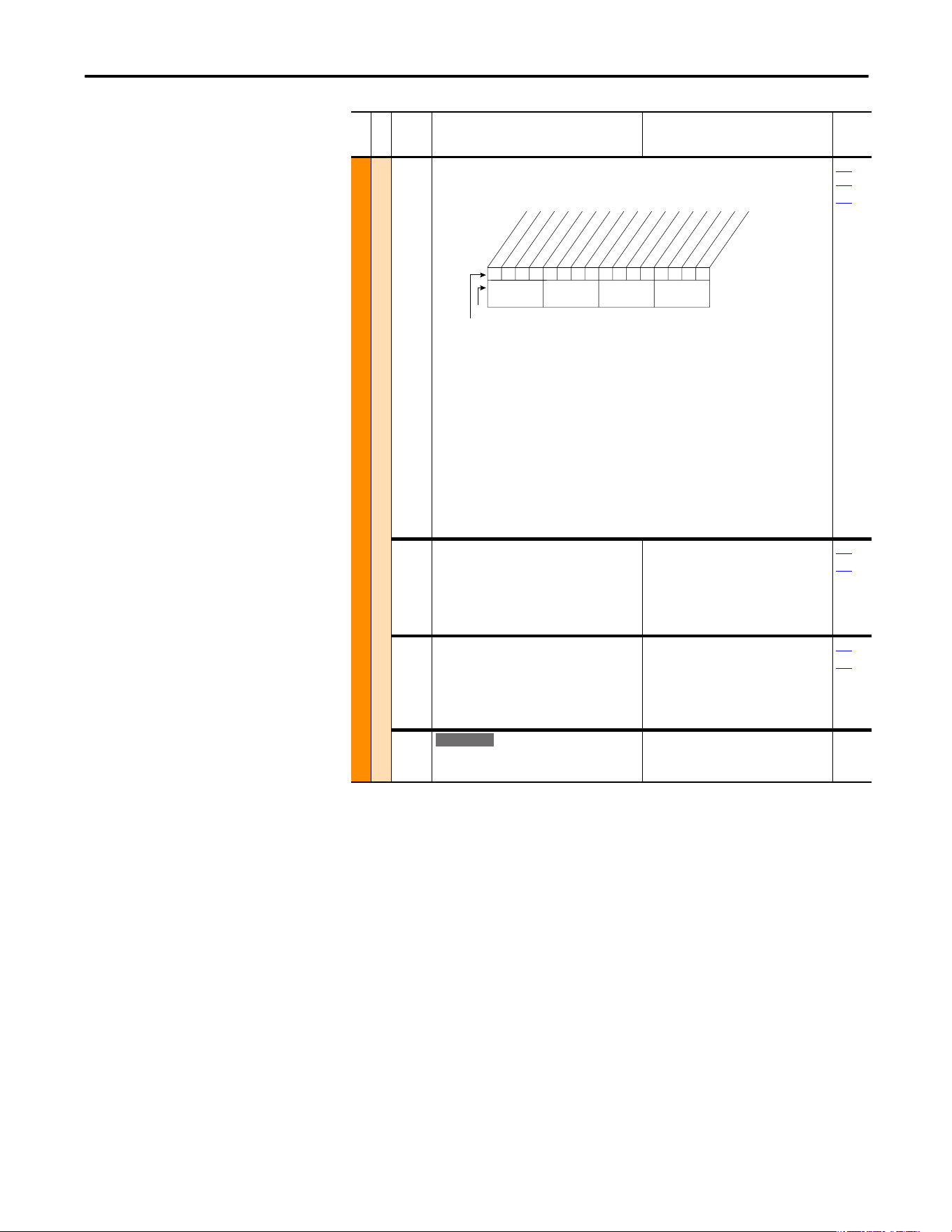
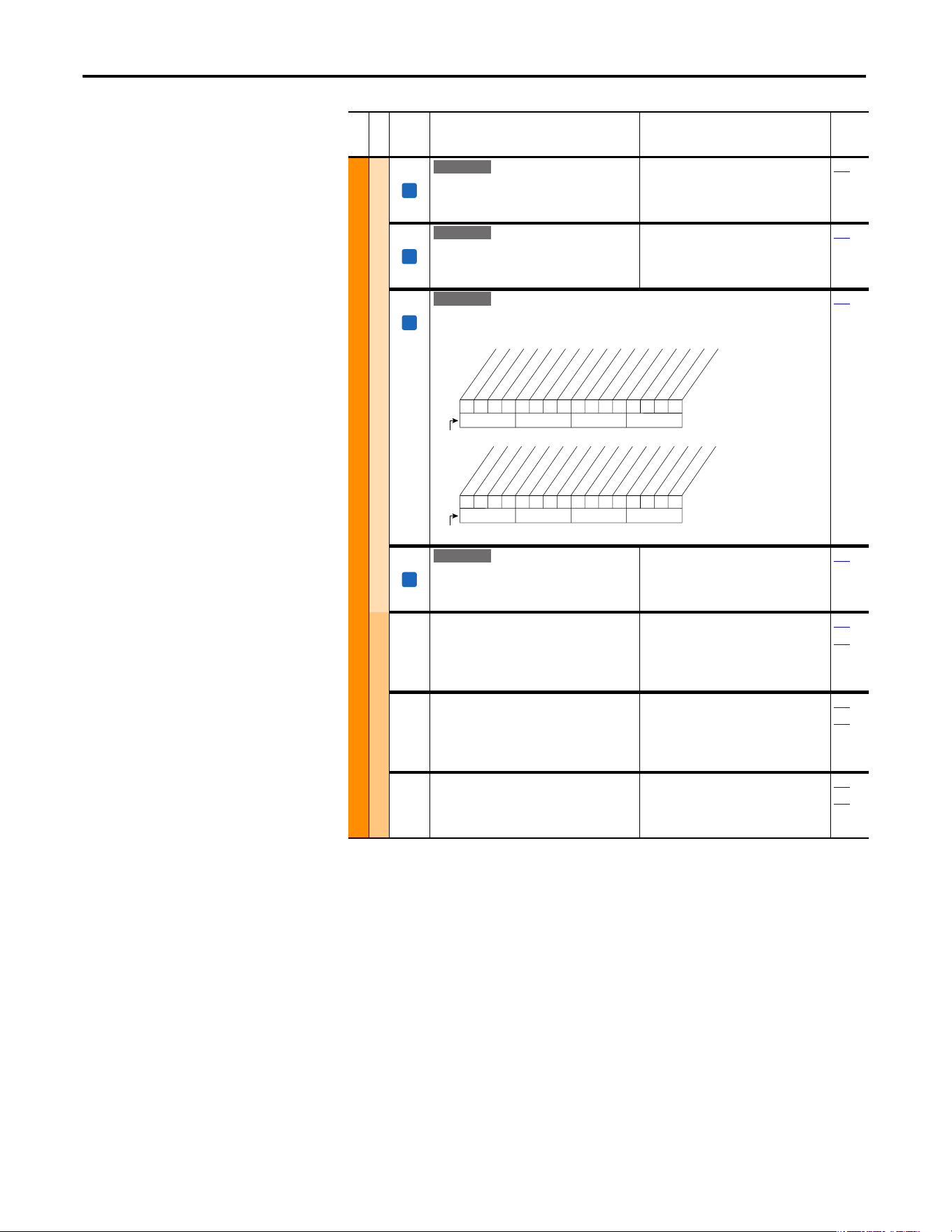
File
Group
No.
Parameter Name and Description Values
Related
UTILITY (file E)
Drive . . .
198 [Load Frm Usr Set]
Loads a previously saved set of parameter values
from a selected user set location in drive
nonvolatile memory to active drive memory.
Default:
Options:
0
0
1
2
3
“Ready”
“Ready”
“User Set 1”
“User Set 2”
“User Set 3”
199
Fault
238 [Fault Config 1]
Enables/disables annunciation of the listed faults.[
Diagnostics
216 [Dig In Status]
Status of the digital
inputs.
Diag-Motor Cntl
549 [Flux Braking %]
Gain adjustment for Flux Braking mode.
(Percentage of normal output voltage.)
This parameter is only viewable when
P196 [Param Access Lvl] = 2
“Reserved.”
Default: 125
Min/Max:100/125
Units:%
166
MOTOR . . .
Torq . . .
059 [SV Boost Filter]
Sets the amount of filtering used to boost voltage
during Sensorless Vector operation.
Default:
Min/Max:
Units:
500
0/32767
1
1x1 0001000x0xxxx
10 01234567891112131415
1 = Enabled
0 = Disable
x = Reserved
Bit #
Factory Default Bit Values
Power Loss
UnderVoltage
HS Low Temp
(3)
Motor OverLd
Shear Pin
AutRst Tries
Decel Inhibt
Motor Therm
(1)
In PhaseLoss
(2)
Load Loss
(2)
ShearPNo Acc
(1)(4
Nibble 1Nibble 2Nibble 3Nibble 4
(1)
Enhanced firmware 1.001 & later.
(2)
Enhanced firmware 2.001 & later.
(3)
Enhanced firmware 4.001 & later.
(4)
Bit 11 enables the shear pin fault to be ignored
during acceleration and deceleration. Using Bit 11 with
Bit 4 set to ‘0’ will have no effect.
000000xx000000xx
10 01234567891112131415
1 =Input Present
0 =Input Not Present
x =Reserved
Bit #
Digital In1
Digital In2
Digital In3
Digital In4
Digital In5
Digital In6
In1 DLogRslt
(1)
In2 DLogRslt
(1)
In3 DLogRslt
(1)
In4 DLogRslt
(1)
In5 DLogRslt
(1)
In6 DLogRslt
(1)
Nibble 1Nibble 2Nibble 3Nibble 4
(1)
Enhanced firmware 2.001 & later.
E C
➊➌➋➏➎➍
Rockwell Automation Publication 20A-UM001P-EN-P - February 2018 13
Programming and Parameters Chapter 1
How Parameters Are
Organized
LED HIM (Human Interface Module)
The LED HIM displays parameters in numbered list order. Access parameters by
first selecting the file letter, then a parameter number.
File Letter Designations
The LED HIM identifies each parameter by file letter and parameter number.
No. Description
➊ File – Lists the major parameter file category.
➋ Group – Lists the parameter group within a file.
➌
No. – Parameter number = Parameter value cannot be changed until drive is stopped.
= 32 bit parameter.
= 32 bit parameter (only in Enhanced Control drive).
= Parameter that is displayed when [Motor Cntl Sel] is set to “4.”
➍ Parameter Name and Description – Parameter name as it appears on an LCD HIM, with a brief description of
the parameters function.
= This parameter is specific to Standard Control drives.
= This parameter is only available with Enhanced Control drives.
➎ Values – Defines the various operating characteristics of the parameter. Three types exist.
ENUM
Default:
Options:
Lists the value that is assigned at the factory. “Read Only” = no default.
Displays the programming selections available.
Bit Bit #: Lists the bit place holder and definition for each bit.
Numeric
Default:
Min/Max:
Units:
Lists the value that is assigned at the factory. “Read Only” = no default.
The range (lowest and highest setting) possible for the parameter.
Unit of measure and resolution as shown on the LCD HIM.
Important: Some parameters have two unit values:
· Analog inputs can be set for current or voltage with 320 [Anlg In Config].
· Values with “.” pertain only to Enhanced Control drive s.
Important: When sending values through DPI ports, simply remove the decimal point to arrive at the correct
value (for example, to send “5.00 Hz,” use “500”).
➏ Related – Lists parameters (if any) that interact with the selected parameter. The symbol “ ” indicates that
additional parameter information is available in Appendix C.
32
32
E C
FV
Standard
E C
E C
IMPORTANT
The PowerFlex 70 Enhanced Control drive does not support the LED HIM.
Esc
ALT
JOG
Sel
Log
Device
Auto/Man
Remove
Out
In
F
R
M
Utility
File E
Parameter 197:
Reset to Defaults

14 Rockwell Automation Publication 20A-UM001P-EN-P - February 2018
Chapter 1 Programming and Parameters
LCD HIM (Human Interface Module)
The LCD HIM displays parameters in a file-group-parameter, or numbered list,
view order. To switch display mode, access the Main Menu, press ALT then Sel
while the cursor is on the parameter selection. In addition, when you use
parameter 196 [Param Access Lvl]
, you have the option to display all parameters,
commonly used parameters, or diagnostic parameters.
Control Options
Two different control options are available for the PowerFlex 70, standard and
enhanced.
• Standard control drives provide volts per hertz and sensorless vector
operation.
• Enhanced control drives support the addition of FVC vector control, the
DriveGuard Safe Off option, and more.
File-group-parameter View
File-group-parameter view simplifies programming by grouping parameters that
are used for similar functions. The parameters are organized into six files in basic
parameter view, or seven files in advanced parameter view. Each file is divided
into groups, and each parameter is an element in a group. By default, the LCD
HIM displays parameters by file-group-parameter view.
Numbered List View
All parameters are in numerical order.

Rockwell Automation Publication 20A-UM001P-EN-P - February 2018 15
Programming and Parameters Chapter 1
Basic Parameter View – Standard Control
Parameter 196 [Param Access Lvl] set to option 0 “Basic.”
File Group Parameters
Monitor Metering Output Freq 001
Commanded Freq 002
Output Current 003
DC Bus Voltage 012
Motor Control Motor Data Motor NP Volts 041
Motor NP FLA 042
Motor NP Hertz 043
Motor NP RPM 044
Motor NP Power 045
Mtr NP Pwr Units 046
Motor OL Hertz 047
Torq Attributes Torque Perf Mode 053
Maximum Voltage 054
Maximum Freq 055
Autotune 061
Speed Command Spd Mode and Limits Minimum Speed 081
Maximum Speed 082
Speed References Speed Ref A Sel 090
Speed Ref A Hi 091
Speed Ref A Lo 092
Speed Ref B Sel 093
Speed Ref B Hi 094
Speed Ref B Lo 095
TB Man Ref Sel 096
TB Man Ref Hi 097
TB Man Ref Lo 098
Discrete Speeds Jog Speed 100
Preset Speed 1…7 101…107
Dynamic Control Ramp Rates Accel Time 1 140
Accel Time 2 141
Decel Time 1 142
Decel Time 2 143
S Curve % 146
Load Limits Current Lmt Sel 147
Current Lmt Val 148
Stop/Brake Modes Stop Mode A 155
Stop Mode B 156
DC Brk Lvl Sel 157
DC Brake Level 158
DC Brake Time 159
Bus Reg Mode A 161
Bus Reg Mode B 162
DB Resistor Type 163
Restart Modes Start At Powerup 168 Auto Rstrt Tries 174 Auto Rstrt Delay 175
Power Loss Power Loss Mode 184 Power Loss Time 185
Utility Direction Config Direction Mode 190
Drive Memory Param Access Lvl 196
Reset To Defalts 197
Load Frm Usr Set 198
Save To User Set 199
Language 201
Diagnostics
Start Inhibits 214 Dig In Status 216 Dig Out Status 217
Faults Fault Config 1 238
Inputs and Outputs Analog Inputs Anlg In Config 320 Analog In1 Hi 322
Analog In1 Lo 323
Analog In2 Hi 325
Analog In2 Lo 326
Analog Outputs Analog Out1 Sel 342
Analog Out1 Hi 343
Analog Out1 Lo 344
Digital Inputs Digital In1…6 Sel 361…366
Digital Outputs Digital Out1 Sel 380
Dig Out1 Level 381
Digital Out2 Sel 384
Dig Out2 Level 385
Monitor
File A
Motor Control
File B
Speed Command
File C
Dynamic Control
File D
Utility
File E
Inputs & Outputs
File J

16 Rockwell Automation Publication 20A-UM001P-EN-P - February 2018
Chapter 1 Programming and Parameters
Basic Parameter View – Enhanced Control
Parameter 196 [Param Access Lvl] set to option 0 “Basic.”
File Group Parameters
Monitor Metering Output Freq 001
Commanded Freq 002
Output Current 003
Torque Current 004
DC Bus Voltage 012
Commanded Torque**024
Motor Control Motor Data Motor NP Volts 041
Motor NP FLA 042
Motor NP Hertz 043
Motor NP RPM 044
Motor NP Power 045
Mtr NP Pwr Units 046
Motor OL Hertz 047
Motor Poles 049
Torq Attributes Motor Cntl Sel 053
Maximum Voltage 054
Maximum Freq 055
Autotune 061
Autotune Torque** 066
Inertia Autotune** 067
Torque Ref A Sel** 427
Torque Ref A Hi** 428
Torque Ref A Lo** 429
Pos Torque Limit** 436
Neg Torque Limit** 437
Speed Feedback Motor Fdbk Type** 412
Encoder PPR** 413
Speed Command Spd Mode and Limits Feedback Select 080 Minimum Speed 081
Maximum Speed 082
Speed References Speed Ref A Sel 090
Speed Ref A Hi 091
Speed Ref A Lo 092
Speed Ref B Sel 093
Speed Ref B Hi 094
Speed Ref B Lo 095
TB Man Ref Sel 096
TB Man Ref Hi 097
TB Man Ref Lo 098
Discrete Speeds Jog Speed 1 100 Preset Speed 1…7 101…107 Jog Speed 2 108
Dynamic Control Ramp Rates Accel Time 1 140
Accel Time 2 141
Decel Time 1 142
Decel Time 2 143
S Curve % 146
Load Limits Current Lmt Sel 147 Current Lmt Val 148
Stop/Brake Modes Stop/Brk Mode A 155
Stop/Brk Mode B 156
DC Brake Lvl Sel 157
DC Brake Level 158
DC Brake Time 159
Bus Reg Mode A 161
Bus Reg Mode B 162
DB Resistor Type 163
Restart Modes Start At Powerup 168 Auto Rstrt Tries 174 Auto Rstrt Delay 175
Power Loss Power Loss Mode 184 Power Loss Time 185
Utility Direction Config Direction Mode 190
Drive Memory Param Access Lvl 196
Reset To Defalts 197
Load Frm Usr Set 198
Save To User Set 199
Language 201
Diagnostics Start Inhibits 214 Dig In Status 216 Dig Out Status 217
Faults Fault Config 1 238
Inputs and Outputs Analog Inputs Anlg In Config 320 Analog In 1 Hi 322
Analog In 2 Hi 325
Analog In 1 Lo 323
Analog In 2 Lo 326
Analog Outputs Analog Out1 Sel 342 Analog Out1 Hi 343
Analog Out1 Lo 344
Digital Inputs Digital In1…6 Sel 361…366
Digital Outputs Digital Out1 Sel 380
Digital Out2 Sel 384
Dig Out1 Level 381
Dig Out2 Level 385
Monitor
File A
Motor Control
File B
Speed Command
File C
Dynamic Control
File D
Utility
File E
Inputs & Outputs
File J
Rockwell Automation Publication 20A-UM001P-EN-P - February 2018 17
Programming and Parameters Chapter 1
Advanced Parameter View – Standard Control
Parameter 196 [Param Access Lvl] set to option 1 “Advanced.”
File Group Parameters
Monitor Metering Output Freq 001
Commanded Freq 002
Output Current 003
Torque Current 004
Flux Current 005
Output Voltage 006
Output Power 007
Output Powr Fctr 008
Elapsed MWh 009
Elapsed Run Time 010
MOP Frequency 011
DC Bus Voltage 012
DC Bus Memory 013
Analog In1 Value 016
Analog In2 Value 017
Drive Data Rated kW 026
Rated Volts 027
Rated Amps 028
Control SW Ver 029
Motor Control Motor Data Motor Type 040
Motor NP Volts 041
Motor NP FLA 042
Motor NP Hertz 043
Motor NP RPM 044
Motor NP Power 045
Mtr NP Pwr Units 046
Motor OL Hertz 047
Motor OL Factor 048
Torq Attributes Torque Perf Mode 053
Maximum Voltage 054
Maximum Freq 055
Compensation 056
Flux Up Mode 057
Flux Up Time 058
Autotune 061
IR Voltage Drop 062
Flux Current Ref 063
Volts per Hertz StAcc Boost 069
Run Boost 070
Break Voltage 071
Break Frequency 072
Speed Command Spd Mode and Limits Speed Mode 080
Minimum Speed 081
Maximum Speed 082
Overspeed Limit 083
Skip Frequency 1 084
Skip Frequency 2 085
Skip Frequency 3 086
Skip Freq Band 087
Speed References Speed Ref A Sel 090
Speed Ref A Hi 091
Speed Ref A Lo 092
Speed Ref B Sel 093
Speed Ref B Hi 094
Speed Ref B Lo 095
TB Man Ref Sel 096
TB Man Ref Hi 097
TB Man Ref Lo 098
Discrete Speeds Jog Speed 100
Preset Speed 1…7 101…107
Speed Trim Trim In Select 117
Trim Out Select 118
Trim Hi 119
Trim Lo 120
Slip Comp Slip RPM @ FLA 121
Slip Comp Gain 122
Slip RPM Meter 123
Process PI PI Configuration 124
PI Control 125
PI Reference Sel 126
PI Setpoint 127
PI Feedback Sel 128
PI Integral Time 129
PI Prop Gain 130
PI Lower Limit 131
PI Upper Limit 132
PI Preload 133
PI Status 134
PI Ref Meter 135
PI Fdback Meter 136
PI Error Meter 137
PI Output Meter 138
Dynamic Control Ramp Rates Accel Time 1 140
Accel Time 2 141
Decel Time 1 142
Decel Time 2 143
S Curve % 146
Load Limits Current Lmt Sel 147
Current Lmt Val 148
Current Lmt Gain 149
Drive OL Mode 150
PWM Frequency 151
Stop/Brake Modes Stop Mode A 155
Stop Mode B 156
DC Brake Lvl Sel 157
DC Brake Level 158
DC Brake Time 159
Bus Reg Gain 160
Bus Reg Mode A 161
Bus Reg Mode B 162
DB
Resistor Type 163
Restart Modes Start At Powerup 168
Flying Start En 169
Flying StartGain 170
Auto Rstrt Tries 174
Auto Rstrt Delay 175
Power Loss Power Loss Mode 184
Power Loss Time 185
Monitor
File A
Motor Control
File B
Speed Command
File C
Dynamic Control
File D

18 Rockwell Automation Publication 20A-UM001P-EN-P - February 2018
Chapter 1 Programming and Parameters
Utility Direction Config Direction Mode 190
HIM Ref Config Save HIM Ref 192
Man Ref Preload 193
MOP Config Save MOP Ref 194
MOP Rate 195
Drive Memory Param Access Lvl 196
Reset To Defalts 197
Load Frm Usr Set 198
Save To User Set 199
Reset Meters 200
Language 201
Voltage Class 202
Drive Checksum 203
Diagnostics Drive Status 1 209
Drive Status 2 210
Drive Alarm 1 211
Drive Alarm 2 212
Speed Ref Source 213
Start Inhibits 214
Last Stop Source 215
Dig In Status 216
Dig Out Status 217
Drive Temp 218
Drive OL Count 219
Motor OL Count 220
Fault Frequency 224
Fault Amps 225
Fault Bus Volts 226
Status 1 @ Fault 227
Status 2 @ Fault 228
Alarm 1 @ Fault 229
Alarm 2 @ Fault 230
Testpoint 1 Sel 234
Testpoint 1 Data 235
Testpoint 2 Sel 236
Testpoint 2 Data 237
Faults Fault Config 1 238
Fault Clear 240
Fault Clear Mode 241
Power Up Marker 242
Fault 1…4 Code 243…249
Fault 1…4 Time 244…250
Alarms Alarm Config 1 259
Communication Comm Control DPI Data Rate 270
Drive Logic Rslt 271
Drive Ref Rslt 272
Drive Ramp Rslt 273
Masks and Owners Logic Mask 276
Start Mask 277
Jog Mask 278
Direction Mask 279
Reference Mask 280
Accel Mask 281
Decel Mask 282
Fault Clr Mask 283
MOP Mask 284
Local Mask 285
Stop Owner 288
Start Owner 289
Jog Owner 290
Direction Owner 291
Reference Owner 292
Accel Owner 293
Decel Owner 294
Fault Clr Owner 295
MOP Owner 296
Local Owner 297
Datalinks Data In A1…D2 300…307
Data Out A1…D2 310…317
Inputs and Outputs Analog Inputs Anlg In Config 320
Anlg In Sqr Root 321
Analog In 1 Hi 322
Analog In 1 Lo 323
Anlg In 1 Loss 324
Analog In 2 Hi 325
Analog In 2 Lo 326
Anlg In 2 Loss 327
Analog Outputs Anlg Out Absolut 341
Analog Out1 Sel 342
Analog Out1 Hi 343
Analog Out1 Lo 344
Digital Inputs Digital In1…6 Sel 361…366
Digital Outputs Digital Out1 Sel 380
Dig Out1 Level 381
Dig Out1 OnTime 382
Dig Out1 OffTime 383
Digital Out2 Sel 384
Dig Out2 Level 385
Dig Out2 OnTime 386
Dig Out2 OffTime 387
File Group Parameters
Utility
File E
Communication
File H
Inputs & Outputs
File J

Rockwell Automation Publication 20A-UM001P-EN-P - February 2018 19
Programming and Parameters Chapter 1
Advanced Parameter View – Enhanced Control
Parameter 196 [Param Access Lvl] set to option 1 “Advanced.”
File Group Parameters
Monitor Metering Output Freq 001
Commanded Freq 002
Output Current 003
Torque Current 004
Flux Current 005
Output Voltage 006
Output Power 007
Output Powr Fctr 008
Elapsed MWh 009
Elapsed Run Time 010
MOP Frequency 011
DC Bus Voltage 012
DC Bus Memory 013
Elapsed kWh 014
Torque Estimate 015
3.x
Analog In1 Value 016
Analog In2 Value 017
Ramped Speed 022
Speed Reference 023
Commanded Torque**024
Speed Feedback 025
Drive Data Rated kW 026
Rated Volts 027
Rated Amps 028
Control SW Ver 029
Motor Control Motor Data Motor Type 040
Motor NP Volts 041
Motor NP FLA 042
Motor NP Hertz 043
Motor NP RPM 044
Motor NP Power 045
Mtr NP Pwr Units 046
Motor OL Hertz 047
Motor OL Factor 048
Motor Poles 049
Motor OL Mode 050
3.x
Torq Attributes Motor Cntl Sel 053
Maximum Voltage 054
Maximum Freq 055
Compensation 056
Flux Up Mode 057
Flux Up Time 058
SV Boost Filter 059
Autotune 061
IR Voltage Drop 062
Flux Current Ref 063
Ixo Voltage Drop 064
Autotune Torque** 066
Inertia Autotune** 067
Torque Ref A Sel** 427
Torque Ref A Hi** 428
Torque Ref A Lo** 429
Torque Setpoint1** 435
Pos Torque Limit** 436
Neg Torque Limit** 437
Control Status** 440
Torq Current Ref** 441
Volts per Hertz StAcc Boost* 069
Run Boost* 070
Break Voltage* 071
Break Frequency* 072
Speed Feedback Motor Fdbk Type 412
Encoder PPR 413
Enc Pos Feedback 414
Encoder Speed 415
Fdbk Filter Sel** 416
Notch FilterFreq** 419
Notch Filter K** 420
Speed Command Spd Mode and Limits Feedback Select 080
Minimum Speed 081
Maximum Speed 082
Overspeed Limit 083
Skip Frequency 1 084
Skip Frequency 2 085
Skip Frequency 3 086
Skip Freq Band 087
Speed/Torque Mod** 088
Rev Speed Limit 454
Speed References Speed Ref A Sel 090
Speed Ref A Hi 091
Speed Ref A Lo 092
Speed Ref B Sel 093
Speed Ref B Hi 094
Speed Ref B Lo 095
TB Man Ref Sel 096
TB Man Ref Hi 097
TB Man Ref Lo 098
Discrete Speeds Jog Speed 1 100 Preset Speed 1…7
101…107
Jog Speed 2 108
Speed Trim Trim % Setpoint 116 Trim In Select 117
Trim Out Select 118
Trim Hi 119
Trim Lo 120
Slip Comp Slip RPM @ FLA 121 Slip Comp Gain* 122 Slip RPM Meter 123
Process PI PI Configuration 124
PI Control 125
PI Reference Sel 126
PI Setpoint 127
PI Feedback Sel 128
PI Integral Time 129
PI Prop Gain 130
PI Lower Limit 131
PI Upper Limit 132
PI Preload 133
PI Status 134
PI Ref Meter 135
PI Fdback Meter 136
PI Error Meter 137
PI Output Meter 138
PI BW Filter 139
PI Deriv Time 459
PI Reference Hi 460
PI Reference Lo 461
PI Feedback Hi 462
PI Feedback Lo 463
Speed Regulator Ki Speed Loop** 445
Kp Speed Loop** 446
Kf Speed Loop** 447
Spd Err Filt BW 448
3.x
Speed Desired BW** 449
Total Inertia** 450
Speed Loop Meter** 451
Monitor
File A
Motor Control
File B
Speed Command
File C

20 Rockwell Automation Publication 20A-UM001P-EN-P - February 2018
Chapter 1 Programming and Parameters
Dynamic Control Restart Modes Powerup Delay 167
Start At Powerup 168
Flying Start En 169
Flying StartGain 170
Auto Rstrt Tries 174
Auto Rstrt Delay 175
Sleep Wake Mode 178
Sleep Wake Ref 179
Wake Level 180
Wake Time 181
Sleep Level 182
Sleep Time 183
Power Loss Gnd Warn Level 177
Power Loss Mode 184
Power Loss Time 185
Load Loss Level 187
Load loss Time 188
Ramp Rates Accel Time 1 140
Accel Time 2 141
Decel Time 1 142
Decel Time 2 143
S Curve % 146
Load Limits Current Lmt Sel 147
Current Lmt Val 148
Current Lmt Gain 149
Drive OL Mode 150
PWM Frequency 151
Droop RPM@FLA 152
Regen Power Lim** 153
Current Rate Lim** 154
Shear Pin Time* 189
Stop/Brake Modes DB While Stopped 145
Stop/Brk Mode A 155
Stop/Brk Mode B 156
DC Brake Lvl Sel 157
DC Brake Level 158
DC Brake Time 159
Bus Reg Ki* 160
Bus Reg Mode A 161
Bus Reg Mode B 162
DB Resistor Type 163
Bus Reg Kp* 164
Bus Reg Kd* 165
Flux Braking 166
Utility Direction Config Direction Mode 190
HIM Ref Config AutoMan Cnfg 192
MOP Config Save MOP Ref 194 MOP Rate 195
Drive Memory Param Access Lvl 196
Reset To Defalts 197
Load Frm Usr Set 198
Save To User Set 199
Reset Meters 200
Language 201
Voltage Class 202
Drive Checksum 203
Dyn UsrSet Cnfg 204
Dyn UserSet Sel 205
Dyn UserSet Actv 206
Diagnostics Drive Status 1 209
Drive Status 2 210
Drive Alarm 1 211
Drive Alarm 2 212
Speed Ref Source 213
Start Inhibits 214
Last Stop Source 215
Dig In Status 216
Dig Out Status 217
Drive Temp 218
Drive OL Count 219
Motor OL Count 220
Mtr OL Trip Time 221
3.x
Drive Status 3 222
3.x
Status 3 @ Fault 223
3.x
Fault Frequency 224
Fault Amps 225
Fault Bus Volts 226
Status 1 @ Fault 227
Status 2 @ Fault 228
Alarm 1 @ Fault 229
Alarm 2 @ Fault 230
Testpoint 1 Sel 234
Testpoint 1 Data 235
Testpoint 2 Sel 236
Testpoint 2 Data 237
Faults Fault Config 1 238
Fault Clear 240
Fault Clear Mode 241
Power Up Marker 242
Fault 1…4 Code 243…249
Fault 1…4 Time 244…250
Alarms Alarm Config 1 259
Scaled Blocks Scale1 In Value 476
Scale1 In Hi 477
Scale1 In Lo 478
Scale2 In Value 482
Scale2 In Hi 483
Scale2 In Lo 484
Communication Comm Control DPI Data Rate 270
Drive Logic Rslt 271
Drive Ref Rslt 272
Drive Ramp Rslt 273
DPI Port Select 274
DPI Port Value 275
DPI Ref Select 298
Masks and Owners Logic Mask 276
Start Mask 277
Jog Mask 278
Direction Mask 279
Reference Mask 280
Accel Mask 281
Decel Mask 282
Fault Clr Mask 283
MOP Mask 284
Local Mask 285
Stop Owner 288
Start Owner 289
Jog Owner 290
Direction Owner 291
Reference Owner 292
Accel Owner 293
Decel Owner 294
Fault Clr Owner 295
MOP Owner 296
Local Owner 297
Datalinks Data In A1…D2 300…307 HighRes Ref 308 Data Out A1…D2 310…317
Security PortMask Act 595
Write Mask Cfg 596
Write Mask Act 597
Logic Mask 276
Logic Mask Act 598
File Group Parameters
Dynamic Control
File D
Utility
File E
Communication
File H
Rockwell Automation Publication 20A-UM001P-EN-P - February 2018 21
Programming and Parameters Chapter 1
* These parameters are available only when parameter 053 [Motor Cntl Sel] is set to option 2 or 3.
** These parameters are available only when parameter 053 [Motor Cntl Sel] is set to option 4.
3.x
Firmware revision 3.002 and later.
Monitor File (File A)
Inputs and Outputs Analog Inputs Anlg In Config 320
Anlg In Sqr Root 321
Analog In 1 Hi 322
Analog In 1 Lo 323
Analog In 1 Loss 324
Analog In 2 Hi 325
Analog In 2 Lo 326
Analog In 2 Loss 327
Analog Outputs Anlg Out Config 340
Anlg Out Absolut 341
Analog Out1 Sel 342
Analog Out1 Hi 343
Analog Out1 Lo 344
Anlg Out Scale 354
Anlg Out1 Setpt 377
Digital Inputs Digital In1…6 Sel 361…366 DigIn DataLogic 411
Digital Outputs Dig Out Setpt 379
Digital Out1 Sel 380
Dig Out1 Level 381
Dig Out1 OnTime 382
Dig Out1 OffTime 383
Digital Out2 Sel 384
Dig Out2 Level 385
Dig Out2 OnTime 386
Dig Out2 OffTime 387
Applications
3.x
Fiber Functions
3.x
Fiber Control 620
3.x
Fiber Status 621
3.x
Sync Time 622
3.x
Traverse Inc 623
3.x
Traverse Dec 624
3.x
Max Traverse 625
3.x
P Jump 626
3.x
File Group Parameters
Inputs & Outputs
File J
Applications
File K
File A
Group
No.
Parameter Name and Description
(1)
Values
Related
MONITOR (file A)
Metering
001 [Output Freq]
Output frequency present at T1, T2, and T3
(U, V, and W)
Default:
Min/Max:
Units:
Read Only
±[Maximum Freq]
0.1 Hz
002 [Commanded Freq]
Value of the active frequency command.
Default:
Min/Max:
Units:
Read Only
±[Maximum Speed]
0.1 Hz
213
003 [Output Current]
The total output current present at
T1, T2, and T3 (U, V, and W).
Default:
Min/Max:
Units:
Read Only
0.0/Drive Rated Amps 2
0.1 Amps
0.01 Amps
004 [Torque Current]
The amount of current that is in phase with the
fundamental voltage component.
Default:
Min/Max:
Units:
Read Only
Drive Rating –2/+2
0.1 Amps
0.01 Amps
005 [Flux Current]
The amount of current that is out of phase with
the fundamental voltage component.
Default:
Min/Max:
Units:
Read Only
Drive Rating –2/+2
0.1 Amps
0.01 Amps
063
006 [Output Voltage]
Output voltage present at terminals
T1, T2, and T3 (U, V, and W).
Default:
Min/Max:
Units:
Read Only
0.0/Drive Rated Volts
0.1V AC
054
202
007 [Output Power]
Output power present at T1, T2, and T3
(U, V, and W). The output power is a calculated
value, dependent on autotune values.
Read Only
0.0/Drive Rated kW 2
0.1 kW
0.01 kW
008 [Output Powr Fctr]
Output power factor.
Default:
Min/Max:
Units:
Read Only
0.00/1.00
0.01
009 [Elapsed MWh]
Accumulated output energy of the drive.
Default:
Min/Max:
Units:
Read Only
0.0/429496729.5 MWh
0.1 MWh
32
E C
E C
32
E C
E C
32
E C
E C
32
E C
E C
32
22 Rockwell Automation Publication 20A-UM001P-EN-P - February 2018
Chapter 1 Programming and Parameters
010 [Elapsed Run Time]
Accumulated time drive is outputting power.
Default:
Min/Max:
Units:
Read Only
0.0/429496729.5 Hrs
0.1 Hrs
011 [MOP Frequency]
Value of the signal at MOP (Motor Operated
Potentiometer).
Default:
Min/Max:
Units:
Read Only
±[Maximum Frequency]
0.1 Hz
194
195
012 [DC Bus Voltage]
Present DC bus voltage level.
Default:
Min/Max:
Units:
Read Only
0.0/Drive Rating Based
0.1V DC
013 [DC Bus Memory]
6 minute average of DC bus voltage level.
Default:
Min/Max:
Units:
Read Only
0.0/Drive Rating Based
0.1V DC
MONITOR (file A)
Metering
014 [Elapsed kWh]
Accumulated output energy of the drive.
Default:
Min/Max:
Units:
Read Only
0.0/429496729.5 kWh
0.1 kWh
015 [Torque Estimate]
Estimated motor torque output as percent of
motor rated torque.
Default:
Min/Max:
Units:
Read Only
±800.0%
0.1%
016
017
[Analog In1 Value]
[Analog In2 Value]
Value of the signal at the analog inputs.
Default:
Min/Max:
Units:
Read Only
0.000/20.000 mA
±10.000V
0.001 mA
0.001 Volts
320 …
327
022 [Ramped Speed]
The value that is shown is the value after the
accel/decel ramp but prior to any corrections
supplied by slip comp, PI, and so on
Default:
Min/Max:
Units:
Read Only
±500.0 Hz
0.1 Hz
023 [Speed Reference]
Summed value of ramped speed and Process PI.
Default:
Min/Max:
Units:
Read Only
±500.0 Hz
0.1 Hz
053
138
152
024 [Commanded Torque]
Final torque reference value after limits and
filtering are applied. % motor rated torque.
Default:
Min/Max:
Units:
Read Only
±800.0%
0.1%
053
025 [Speed Feedback]
Value of actual motor speed, which is measured
by encoder feedback or estimated.
Default:
Min/Max:
Units:
Read Only
±500.0 Hz
0.1 Hz
053
Drive Data
026 [Rated kW]
Drive power rating.
Default:
Min/Max:
Units:
Read Only
0.37/15.0 kW
0.00/300.00 kW
0.01 kW
027 [Rated Volts]
The drive input voltage class (208, 240, 400, and
so on.).
Default:
Min/Max:
Units:
Read Only
208/600 Volt
0.0/6553.5 Volt
0.1V AC
028 [Rated Amps]
The drive rated output current.
Default:
Min/Max:
Units:
Read Only
1.1/32.2 Amps
0.0/6553.5 Amps
0.1 Amps
029 [Control SW Ver]
Main Control Board software version/firmware
revision.
Default:
Min/Max:
Units:
Read Only
0.000/65.256
0.0/65.535
0.001
196
(1) See page 13 for Symbol Descriptions.
File A
Group
No.
Parameter Name and Description
(1)
Values
Related
32
32
E C
E C v3
E C
E C
FV
E C v2
E C v2
32
E C
E C
E C
E C
Rockwell Automation Publication 20A-UM001P-EN-P - February 2018 23
Programming and Parameters Chapter 1
Motor Control File (File B)
File B
Group
No.
Parameter Name and Description
(1)
Values
Related
MOTOR CONTROL (file B)
Motor Data
040 [Motor Type]
Set to match the type of motor connected.
(1)
Important: Selecting option 1 or 2 also
requires selection of “Custom V/Hz,” option 2 in
parameter 53.
Default:
Options:
0
0
1
2
“Induction”
“Induction”
“Synchr Reluc”
(1)
“Synchr PM”
(1)
053
041 [Motor NP Volts]
Set to the motor nameplate rated volts.
• 208/240 => 240.0V
• 400/480 => 480.0V
• 600/600 => 600.0V
Default:
Min/Max:
Units:
Drive Rating Based
0.0/[Rated Volts]
0.1V AC
042 [Motor NP FLA]
Set to the motor nameplate rated full load
amps.
Default:
Min/Max:
Units:
Drive Rating Based
0.0/[Rated Amps] 2
0.1 Amps
047
048
148
043 [Motor NP Hertz]
Set to the motor nameplate rated frequency.
Default:
Min/Max:
Units:
Drive Rating Based
5.0/400.0 Hz
5.0/500.0 Hz
0.1 Hz
044 [Motor NP RPM]
Set to the motor nameplate rated rpm.
Default:
Min/Max:
Units:
Drive Rating Based
60/30000 rpm
1 rpm
049
080
121
045 [Motor NP Power]
Set to the motor nameplate rated power.
(1) See [Mtr NP Pwr Units].
Default:
Min/Max:
Units:
Drive Rating Based
0.00/100.00
0.00/412.48
0.01 kW/Hp
(1)
046
046 [Mtr NP Pwr Units]
Selects the motor power units to be used.
Default:
Options: 0
1
Drive Rating Based
“Horsepower”
“kilowatts”
045
047 [Motor OL Hertz]
Selects a lower output frequency than where
the motor operating current is derated. The
motor thermal overload generates a fault at
lower levels of current.
Default:
Min/Max:
Units:
Motor NP Hz/3
0.0/500.0 Hz
0.1 Hz
042
220
048 [Motor OL Factor]
Sets operating level for motor overload service
factor.
Default:
Min/Max:
Units:
1.00
0.20/2.00
0.01
042
220
P42 [Motor NP FLA] x P48 [Motor OL Factor] = Operating Level
049 [Motor Poles]
Defines the number of poles in the motor.
Default:
Min/Max:
Units:
4
2/40
2 Pole
043
044
Number of Poles = (120 x P43 [Motor NP Hertz]) / P44 [Motor NP RPM]
E C
32
E C
E C
24 Rockwell Automation Publication 20A-UM001P-EN-P - February 2018
Chapter 1 Programming and Parameters
MOTOR CONTROL (file B)
Motor Data
050 [Motor OL Mode]
If “0” [Motor OL Count], P220 is reset to zero by a drive reset or a power cycle. If “1” the value
is maintained. A “1” to “0” transition resets [Motor OL Count], P220 to zero.
220
Torq Attributes
053 [Torque Perf Mode]
Sets the method of motor torque production.
Default:
Options:
0
0
1
2
3
“Sensrls Vect”
“Sensrls Vect”
“SV Economize”
“Custom V/Hz”
“Fan/Pmp V/Hz”
062
063
069
070
[Motor Cntl Sel]
Sets the method of motor control that is used in
the drive.
Important: “FVC Vector” mode requires
autotuning of the motor, both coupled and
uncoupled to the load.
(1)
Enhanced firmware revision 2.001 and later.
Default:
Options:
0
0
1
2
3
4
“Sensrls Vect”
“Sensrls Vect”
“SV Economize”
“Custom V/Hz”
“Fan/Pmp V/Hz”
“FVC Vector”
(1)
054 [Maximum Voltage]
Sets the highest voltage that the drive can
output.
Default:
Min/Max:
Units:
Drive Rated Volts
Rated Volts 0.25/Rated Volts
based on high voltage rating, for
example:
· 208/240 240.0V
· 400/480 480.0V
· 600/600 600.0V
0.1V AC
197
055 [Maximum Freq]
Sets the highest frequency that the drive can
output.
Refer to parameter 083 [Overspeed Limit].
Default:
Min/Max:
Units:
110.0 Hz or 130.0 Hz
5.0/400.0 Hz
5.0/500.0 Hz
0.1 Hz
082
083
202
298
File B
Group
No.
Parameter Name and Description
(1)
Values
Related
E C v3
xxx 0xxxxxxxxxxxx
10 01234567891112131415
1 = Enabled
0 = Disabled
x = Reserved
Bit #
Factory Default Bit Values
Pwr Cyc Ret
Nibble 1Nibble 2Nibble 3Nibble 4
Standard
E C
E C
Rockwell Automation Publication 20A-UM001P-EN-P - February 2018 25
Programming and Parameters Chapter 1
MOTOR CONTROL (file B)
Torq Attributes
056 [Compensation]
Enables/disables correction options.
Option Descriptions:
• Reflect Wave – Provides reflected wave overvoltage protection for long cable lengths.
(typically enabled).
• Enable Jerk – In non-FVC Vector modes, disabling jerk removes a short S-curve at the start
of the accel/decel ramp.
• Ixo AutoCalc – Not functional – reserved for future enhancements.
• Xsistor Diag – Power transistor power diagnostic tests run at each start command.
• Rs Adapt – only FVC w/Encoder – Disabling can improve torque regulation at lower
speeds (typically not needed).
• PWM Freq Lock – Keeps the PWM frequency from decreasing to 2 kHz at low operating
frequencies in FVC Vector mode without encoder.
• DigIn DatLog – Enables logic functions that can be applied to parameter 411 [DigIn
DataLogic] and the specified digital input.
140
…
143
411
057 [Flux Up Mode]
Auto = Flux is established for a calculated time
period based on motor nameplate data. [Flux
Up Time] is not used.
Manual = Flux is established for [Flux Up Time]
before acceleration.
Default:
Options:
0
0
1
“Manual”
“Manual”
“Automatic”
053
058
058 [Flux Up Time]
Sets the amount of time the drive uses to try
and achieve full motor stator flux. When a Start
command is issued, DC current at current limit
level is used to build stator flux before
accelerating.
Default:
Min/Max:
Units:
0.00 s
0.00/5.00 s
0.01 s
053
058
059 [SV Boost Filter]
Sets the amount of filtering used to boost
voltage during Sensorless Vector operation.
Default:
Min/Max:
Units:
500
0/32767
1
File B
Group
No.
Parameter Name and Description
(1)
Values
Related
10111xx1x0xxxxxx
10 01234567891112131415
1 =Enabled
0 =Disabled
x =Reserved
Bit #
Factory Default Bit Values
Reflect Wave
Enable Jerk
Ixo AutoCalc
Xsistor Diag
(1)
Rs Adapt
(2)
PWM Freq Lock
(2)
DigIn DatLog
(2)
Nibble 1Nibble 2Nibble 3Nibble 4
(1)
Enhanced firmware 1.001 & later.
(2)
Enhanced firmware 2.001 & later.
E C
26 Rockwell Automation Publication 20A-UM001P-EN-P - February 2018
Chapter 1 Programming and Parameters
MOTOR CONTROL (file B)
Torq Attributes
061 [Autotune]
Provides a manual or automatic method for
setting P62 [IR Voltage Drop] and P63 [Flux
Current Ref] to affect sensorless vector
performance. Valid only when P53 is set to
“Sensrls Vect”, “SV Economize”, or “FVC Vector.”
Default:
Options:
3
0
1
2
3
“Calculate”
“Ready”
“Static Tune”
“Rotate Tune”
“Calculate”
053
062
“Ready” (0) = Parameter returns to this setting following a “Static Tune” or “Rotate Tune.” It
also permits manually setting P62 [IR Voltage Drop], P64 [Ixo Voltage Drop] and P63 [Flux
Current Ref].
“Static Tune” (1) = A temporary command that initiates a non-rotational motor stator
resistance test for the best possible automatic setting of P62 [IR Voltage Drop] in all valid
modes and a non-rotational motor leakage inductance test for the best possible automatic
setting of P64 [Ixo Voltage Drop] in “FVC Vector” mode. A start command is required
following initiation of this setting. The parameter returns to “Ready” (0) following the test,
and then another start transition is required to operate the drive in normal mode. This is used
when the motor cannot be rotated.
“Rotate Tune” (2) = A temporary command that initiates a “Static Tune” followed by a
rotational test for the best possible automatic setting of P63 [Flux Current Ref]. In “FVC
Vector” mode, with encoder feedback, a test for the best possible automatic setting of P121
[Slip RPM @ FLA] is also run. A start command is required following initiation of this setting.
The parameter returns to “Ready” (0) following the test, and then another start transition is
required to operate the drive in normal mode. Important: If you are using rotate tune for
“Sensrls Vect” mode, uncouple the motor from the load or results can be invalid. With “FVC
Vector,” either a coupled or uncoupled load produces a valid result.
“Calculate” (3) = This setting uses motor nameplate data to automatically set P62 [IR Voltage
Drop], P64 [Ixo Voltage Drop], P63 [Flux Current Ref] and P121 [Slip RPM @ FLA].
062 [IR Voltage Drop]
Value of voltage drop across the resistance of
the motor stator at rated motor current. Used
only when parameter 53 is set to “Sensrls Vect”,
“SV Economize”, or “FVC Vector.”
Default:
Min/Max:
Units:
Drive Rating Based
0.0/[Motor NP Volts]0.5
0.1V AC
053
061
063 [Flux Current Ref]
Value of amps for full motor flux. Used only
when parameter 53 is set to “Sensrls Vect”, “SV
Economize”, or “FVC Vector.”
Default:
Min/Max:
Units:
Drive Rating Based
[Motor NP FLA] 0.05/[Motor
NP FLA] 0.9
0.01 Amps
053
061
File B
Group
No.
Parameter Name and Description
(1)
Values
Related
ATTENTION: Rotation of the motor in an undesired direction can
occur during this procedure. To guard against possible injury
and/or equipment damage, it is recommended that the motor is
disconnected from the load before proceeding.
32
Rockwell Automation Publication 20A-UM001P-EN-P - February 2018 27
Programming and Parameters Chapter 1
MOTOR CONTROL (file B)
Torq Attributes
064 [IXo Voltage Drop]
Value of voltage drop across the leakage
inductance of the motor at rated motor current.
Used only when parameter 53 is set to “FVC
Vector.”
Default:
Min/Max:
Units:
Based on Drive Rating
0.0/Motor NP Volts
0.1V AC
053
061
066 [Autotune Torque]
Specifies motor torque that is applied to the
motor during the flux current and inertia tests
that are performed during an autotune.
Default:
Min/Max:
Units:
50.0%
0.0/150.0%
0.1%
053
067 [Inertia Autotune]
Provides an automatic method of setting [Total
Inertia]. This test is automatically run during
Start-Up motor tests. Important: Use this
when the motor is coupled to the load. Results
can be invalid if the load is not coupled to the
motor during this procedure.
“Ready” = Parameter returns to this setting
following a completed inertia tune.
“Inertia Tune” = A temporary command that
initiates an inertia test of the motor/load
combination. The motor ramps up and down,
while the drive measures the amount of inertia.
Default:
Options:
0
0
1
“Ready”
“Ready”
“Inertia Tune”
053
066
445
446
449
450
427 [Torque Ref A Sel]
Selects the source of the external torque
reference to the drive. How this reference is
used is dependent upon P88 [Speed/Torque
Mod].
(1)
See Appendix B for DPI port locations.
Default:
Options:
0
0
1
2
3…17
18…22
23
24
25
26
“Torque Setpt”
“Torque Setpt”
“Analog In 1”
“Analog In 2”
“Reserved”
“DPI Port 1…5”
(1)
“Reserved”
“Disabled”
“Scale Block1”
“Scale Block2”
053
088
320…
327
428…
437
428 [Torque Ref A Hi]
Scales the upper value of the [Torque Ref A Sel]
selection when the source is an analog input.
Default:
Min/Max:
Units:
100.0%
±800.0%
0.1%
053
427
429 [Torque Ref A Lo]
Scales the lower value of the [Torque Ref A Sel]
selection when the source is an analog input.
Default:
Min/Max:
Units:
0.0%
±800.0%
0.1%
053
427
435 [Torque Setpoint1]
Provides an internal fixed value for Torque
Setpoint when [Torque Ref Sel] is set to “Torque
Setpt.”
Default:
Min/Max:
Units:
0.0%
±800.0%
0.1%
053
427
File B
Group
No.
Parameter Name and Description
(1)
Values
Related
FV
E C v2
FV
E C v2
FV
E C v2
FV
E C v2
FV
E C v2
FV
E C v2
FV
E C v2
28 Rockwell Automation Publication 20A-UM001P-EN-P - February 2018
Chapter 1 Programming and Parameters
MOTOR CONTROL (file B)
Torq Attributes
436 [Pos Torque Limit]
Defines the torque limit for the positive torque
reference value. The reference cannot exceed
this value.
Default:
Min/Max:
Units:
200.0%
0.0/800.0%
0.1%
053
437 [Neg Torque Limit]
Defines the torque limit for the negative torque
reference value. The reference cannot exceed
this value.
Default:
Min/Max:
Units:
–200.0%
–800.0/0.0%
0.1%
053
440 [Control Status]
Displays a summary status of any condition that can be
limiting either the current or the torque reference.
Read Only
053
441 [Torq Current Ref]
Displays the torque current reference value that
is present at the output of the current rate
limiter (parameter 154).
Default:
Min/Max:
Units:
Read Only
±3276.7 Amps
0.1 Amps
053
Volts per Hertz
069 [Start/Acc Boost]
Sets the voltage boost level for starting and
acceleration when “Custom V/Hz” mode is
selected.
Refer to parameter 083 [Overspeed Limit].
Default:
Min/Max:
Units:
Drive Rating Based
0.0/[Motor NP Volts] 0.25
0.1V AC
053
070
070 [Run Boost]
Sets the boost level for steady state or
deceleration when “Fan/Pmp V/Hz” or “Custom
V/Hz” modes are selected.
Refer to the diagram at parameter 083.
Default:
Min/Max:
Units:
Drive Rating Based
0.0/[Motor NP Volts] 0.25
0.1V AC
053
069
071 [Break Voltage]
Sets the [Break Frequency] output voltage of
the drive.
Refer to parameter 083 [Overspeed Limit].
Default:
Min/Max:
Units:
[Motor NP Volts] 0.25
0.0/[Motor NP Volts]
0.1V AC
053
072
File B
Group
No.
Parameter Name and Description
(1)
Values
Related
FV
E C v2
FV
E C v2
FV
E C v2
0000000000000000
10 01234567891112131415
1 =Condition True
0 =Condition False
x =Reserved
Bit #
NegTrqCurLim
PosTrqCurLim
NegFlxCurLim
PosFlxCurLim
NegTrqLimit
PosTrqLimit
NegPwrTrqLim
PosPwrTrqLim
Min Slip Lim
Max Slip Lim
MinTrqCurLim
VelTrqRef
TorqRef
FldWeakSts
Observe Sts
VltLimLeakag
00000xxxxxxxxxxx
26 161718192021222324252728293031
1 =Condition True
0 =Condition False
x =Reserved
Bit #
VltLimStator
DrvVoltLim
FluxBrake
Economize
RevPhaseMot
FV
E C v2
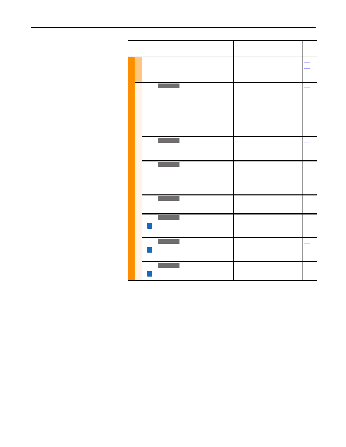
Rockwell Automation Publication 20A-UM001P-EN-P - February 2018 29
Programming and Parameters Chapter 1
MOTOR CONTROL (file B)
Volts per Hertz
072 [Break Frequency]
Sets the [Break Voltage] output frequency of
the drive.
Refer to parameter 083 [Overspeed Limit].
Default:
Min/Max:
Units:
[Motor NP Hertz] 0.25
0.0/[Maximum Freq]
0.1 Hz
053
071
Speed Feedback
412 [Motor Fdbk Type]
Selects the encoder type; single channel or
quadrature. Options 1 and 3 detect a loss of
encoder signal (when you are using differential
inputs) regardless of the [Feedback Select],
param. 080 setting. For FVC Vector mode, use a
quadrature encoder only (option 0/1). If a single
channel encoder is used (option 2/3) in
sensorless vector or V/Hz mode, select “Reverse
Dis” (option 2) in param. 190.
Default:
Options:
0
0
1
2
3
“Quadrature”
“Quadrature”
“Quad Check”
“Single Chan”
“Single Check”
080
088
413 [Encoder PPR]
Contains the encoder pulses per revolution. For
improved operation in FVC Vector mode, PPR
can be (64 x motor poles).
Default:
Min/Max:
Units:
1024 PPR
1/20000 PPR
1 PPR
080
414 [Enc Pos Feedback]
Displays raw encoder pulse count. For single
channel encoders, this count increases (per rev.)
by the amount in [Encoder PPR]. For quadrature
encoders this count increases by 4 times the
amount that is defined in [Encoder PPR].
Default:
Min/Max:
Units:
Read Only
±2147483647
1
415 [Encoder Speed]
Provides a monitoring point that reflects speed
as seen from the feedback device.
Default:
Min/Max:
Units:
Read Only
±500.0 Hz
0.1 Hz
416 [Fdbk Filter Sel]
Selects the type of feedback filter desired.
“Light” uses a 35/49 radian feedback filter.
“Heavy” uses a 20/40 radian feedback filter.
Default:
Options:
0
0
1
2
“None”
“None”
“Light”
“Heavy”
419 [Notch FilterFreq]
Sets the center frequency for an optional 2-pole
notch filter. Filter is applied to the torque
command. “0” disables this filter.
Default:
Min/Max:
Units:
0.0 Hz
0.0/500.0 Hz
0.1 Hz
053
420 [Notch Filter K]
Sets the width for the 2-pole notch filter.
Default:
Min/Max:
Units:
0.3
0.1/0.9
0.1
053
(1) See page 13 for Symbol Descriptions.
File B
Group
No.
Parameter Name and Description
(1)
Values
Related
E C v2
E C v2
E C v2
E C v2
FV
E C v2
FV
E C v2
FV
E C v2
30 Rockwell Automation Publication 20A-UM001P-EN-P - February 2018
Chapter 1 Programming and Parameters
Speed Command File (File C)
File C
Group
No.
Parameter Name and Description
(1)
Values
Related
SPEED COMMAND (file C)
Spd Mode and Limits
080 [Speed Mode]
Sets the method of speed regulation.
Default:
Options:
0
0
1
2
“Open Loop”
“Open Loop”
“Slip Comp”
“Process PI”
121…
138
125
412
413
[Feedback Select]
Selects the source for motor speed feedback.
Note that all selections are available when you
are using Process PI.
“Open Loop” (0) - no encoder is present, and
slip compensation is not needed.
“Slip Comp” (1) - tight speed control is needed,
and encoder is not present.
“Encoder” (3) - an encoder is present.
“Simulator” (5) - Simulates a motor for testing
drive operation and interface check.
Default:
Options:
0
0
1
2
3
4
5
“Open Loop”
“Open Loop”
“Slip Comp”
“Reserved”
“Encoder”
“Reserved”
“Simulator”
081 [Minimum Speed]
Sets the low limit for speed reference after
scaling is applied.
Refer to parameter 083 [Overspeed Limit].
Default:
Min/Max:
Units:
0.0 Hz
0.0/[Maximum Speed]
0.1 Hz
092
095
082 [Maximum Speed]
Sets the high limit for speed reference after
scaling is applied.
Refer to parameter 083 [Overspeed Limit].
Default:
Min/Max:
Units:
50.0 Hz or 60.0 Hz
(Dependent on voltage class)
5.0/400.0 Hz
5.0/500.0 Hz
0.1 Hz
055
083
091
094
202
298
083 [Overspeed Limit]
Sets the incremental amount of the output
frequency (greater than [Maximum Speed]) for
functions such as slip compensation.
P82 [Maximum Speed] + P83 [Overspeed
Limit] must be P55 [Maximum Freq]
Default:
Min/Max:
Units:
10.0 Hz
0.0/20.0 Hz
0.1 Hz
055
082
Standard
E C
E C
Allowable Output Frequency Range
Bus Regulation or Current Limit
Voltage
Frequency
Allowable Output Frequency Range
Normal Operation
Allowable Reference Frequency Range
Frequency Trim due to
Speed Control Mode
Max Volts
Motor Volts
Break Volts
Start Boost
Run
0 Min
Speed
Motor
Hz
Max
Speed
Output
Freq Limit
Max
Freq
Break
Frequency
Overspeed
Limit
Rockwell Automation Publication 20A-UM001P-EN-P - February 2018 31
Programming and Parameters Chapter 1
SPEED COMMAND (file C)
Spd Mode and Limits
084
085
086
[Skip Frequency 1]
[Skip Frequency 2]
[Skip Frequency 3]
Sets a frequency where the drive does not
operate.
Default:
Default:
Default:
Min/Max:
Units:
0.0 Hz
0.0 Hz
0.0 Hz
±500.0 Hz
0.1 Hz
087
087 [Skip Freq Band]
Determines the bandwidth around a skip
frequency. [Skip Freq Band] is split, applying 1/
2 above and 1/2 below the actual skip
frequency. The same bandwidth applies to all
skip frequencies.
Default:
Min/Max:
Units:
0.0 Hz
0.0/30.0 Hz
0.1 Hz
084
088 [Speed/Torque Mod]
Selects the torque reference source.
“Zero Torque” (0) - torque command = 0.
“Speed Reg” (1) - drive operates as a speed
regulator.
“Torque Reg” (2) - an external torque reference
is used for the torque command.
Default:
Options:
1
0
1
2
3
4
5
“Speed Reg”
“Zero Torque”
“Speed Reg”
“Torque Reg”
“Min Torq/Spd”
“Max Torq/Spd”
“Sum Torq/Spd”
053
361…
366
“Min Torq/Spd” (3) - selects the smallest algebraic value to regulate to when the torque
reference and torque that is generated from the speed regulator are compared.
“Max Torq/Spd” (4) - selects the largest algebraic value when the torque reference and the
torque that is generated from the speed regulator are compared.
“Sum Torq/Spd” (5) - selects the sum of the torque reference and the torque that is
generated from the speed regulator.
454 [Rev Speed Limit]
Sets a limit on speed in the negative direction.
A value of zero disables this parameter and uses
[Min Speed] for minimum speed.
Default:
Min/Max:
Units:
0.0 Hz
–[Max Speed]/0.0 Hz
0.1 Hz
File C
Group
No.
Parameter Name and Description
(1)
Values
Related
FV
E C v2
ATTENTI ON: The speed of the drive could reach P82 [Maximum
Speed] + P83 [Overspeed Limit] to meet required torque when
any of the torque modes have been selected. Equipment
damage and/or personal injury can result.
E C
32 Rockwell Automation Publication 20A-UM001P-EN-P - February 2018
Chapter 1 Programming and Parameters
SPEED COMMAND (file C)
Speed References
090 [Speed Ref A Sel]
Selects the source of the speed reference to the
drive unless [Speed Ref B Sel] or [Preset Speed
1…7] is selected.
For more information on selecting a speed
reference source, see Speed Reference Control
on page 110.
(1)
See External and Internal Connections on page 93
for DPI port locations.
(2)
Only Enhanced Control Drives.
Default:
Options:
2
1
2
3…7
8
9
10
11
12
13
14
15
16
17
18
19
20
21
22
23, 24
25
26
27…29
30
“Analog In 2”
“Analog In 1”
“Analog In 2”
“Reserved”
“Encoder”
“MOP Level”
“Reserved”
“Preset Spd1”
“Preset Spd2”
“Preset Spd3”
“Preset Spd4”
“Preset Spd5”
“Preset Spd6”
“Preset Spd7”
“DPI Port 1”
(1)
“DPI Port 2”
(1)
“DPI Port 3”
(1)
“Reserved”
“DPI Port 5”
(1)
“Reserved”
“Scale Block1”
“Scale Block2”
“Reserved”
“HighRes Ref”
(2)
002
091…
093
101…
107
117…
120
192…
194
213
272
273
320
361…
366
091 [Speed Ref A Hi]
Scales the upper value of the [Speed Ref A Sel]
selection when the source is an analog input.
Default:
Min/Max:
Units:
[Maximum Speed]
±[Maximum Speed]
0.1 Hz
082
090
092 [Speed Ref A Lo]
Scales the lower value of the [Speed Ref A Sel]
selection when the source is an analog input.
Default:
Min/Max:
Units:
0.0 Hz
±[Maximum Speed]
0.1 Hz
081
090
093 [Speed Ref B Sel]
See [Speed Ref A Sel].
Default:
Options:
11 “Preset Spd1”
See [Speed Ref A Sel]
See
090
094 [Speed Ref B Hi]
Scales the upper value of the [Speed Ref B Sel]
selection when the source is an analog input.
Default:
Min/Max:
Units:
[Maximum Speed]
±[Maximum Speed]
0.1 Hz
093
095 [Speed Ref B Lo]
Scales the lower value of the [Speed Ref B Sel]
selection when the source is an analog input.
Default:
Min/Max:
Units:
0.0 Hz
±[Maximum Speed]
0.1 Hz
090
093
File C
Group
No.
Parameter Name and Description
(1)
Values
Related
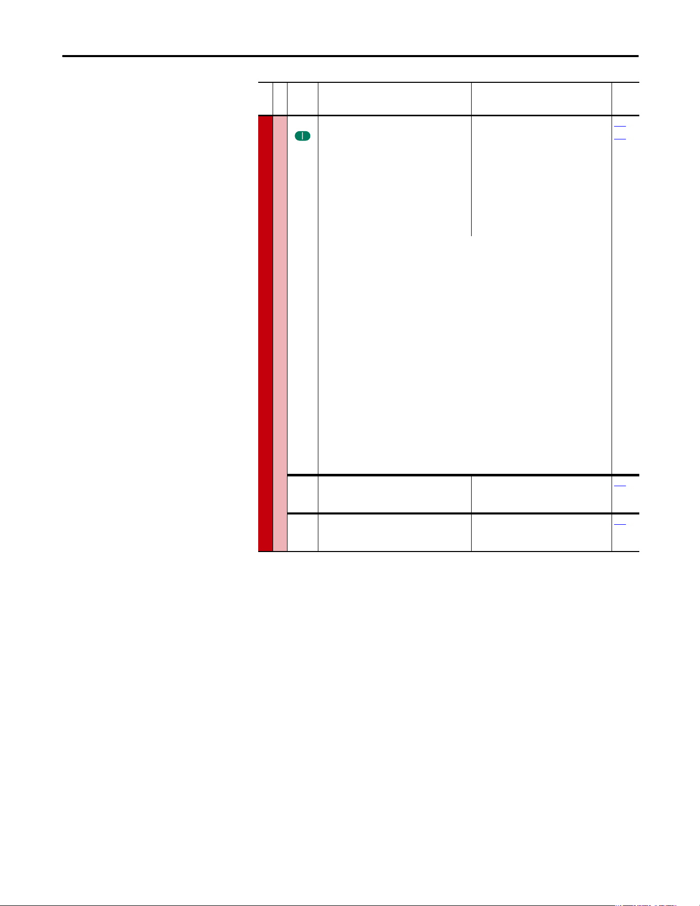
Rockwell Automation Publication 20A-UM001P-EN-P - February 2018 33
Programming and Parameters Chapter 1
SPEED COMMAND
Speed References
096 [TB Man Ref Sel]
Sets the manual speed reference source when a
digital input (parameter 361…366) is
configured for “Auto/Manual.”
•
(1)
“Analog In 2” is not a valid selection if it
was selected for any of the following:
- P117 [Trim In Select]
- P128 [PI Feedback Sel]
- P126 [PI Reference Sel]
- P147 [Current Lmt Sel]
- P179 [Sleep Wake Ref]
Default:
Options:
1
1
2
3…8
9
10…17
18
19
20
“Analog In 1”
“Analog In 1”
“Analog In 2”
(1)
“Reserved”
“MOP Level”
“Reserved”
“DPI Port 1”
(2)
“DPI Port 2”
(2)
“DPI Port 3”
(2)
097
098
(2)
Requires a Series B HIM with firmware revision v5.004.01 or later.
Selects the HIM to provide the manual speed reference when a digital input is configured for
“Au to/Manual.”
Additionally, if [Man Ref Preload], parameter 193 is set to “Enabled,” the automatic speed
reference is preloaded into the HIM when the drive switches to Manual mode from
Automatic mode.
• Set [Save HIM Ref], parameter 192, bit 1 (Manual Mode) as desired.
• Set [TB Man Ref Sel] to the desired drive reference when in Manual Mode. If set to one of
the DPI Ports, then [Man Ref Preload] must be set to enable or disable reference preload
of the current speed. Connect a HIM to the DPI Port selected.
• When Manual mode is requested through the terminal block digital input, the drive
evaluates if Manual mode can be granted.
• If [TB Man Ref Sel] is set to a DPI Port and [Man Ref Preload] is enabled, the drive transfers
the last value of the automatic speed reference to the HIM. The HIM is now the speed
reference source. The terminal block has exclusive control based on [Save HIM Ref], bit 1
(Manual Mode). If [Man Ref Preload] is disabled, the HIM is now the speed reference
source. The terminal block has exclusive control based on [Save HIM Ref], bit 1 (Manual
Mode).
Important: the HIM does not enter Manual mode, it is only the reference source for the
terminal block.
When Auto mode is requested through the terminal block, the drive changes to Auto mode
and returns control and reference to the previous state before Manual mode was requested.
097 [TB Man Ref Hi]
Scales the upper value of the [TB Man Ref Sel]
selection when the source is an analog input.
Default:
Min/Max:
Units:
[Maximum Speed]
±[Maximum Speed]
0.1 Hz
096
098 [TB Man Ref Lo]
Scales the lower value of the [TB Man Ref Sel]
selection when the source is an analog input.
Default:
Min/Max:
Units:
0.0 Hz
±[Maximum Speed]
0.1 Hz
096
File C
Group
No.
Parameter Name and Description
(1)
Values
Related
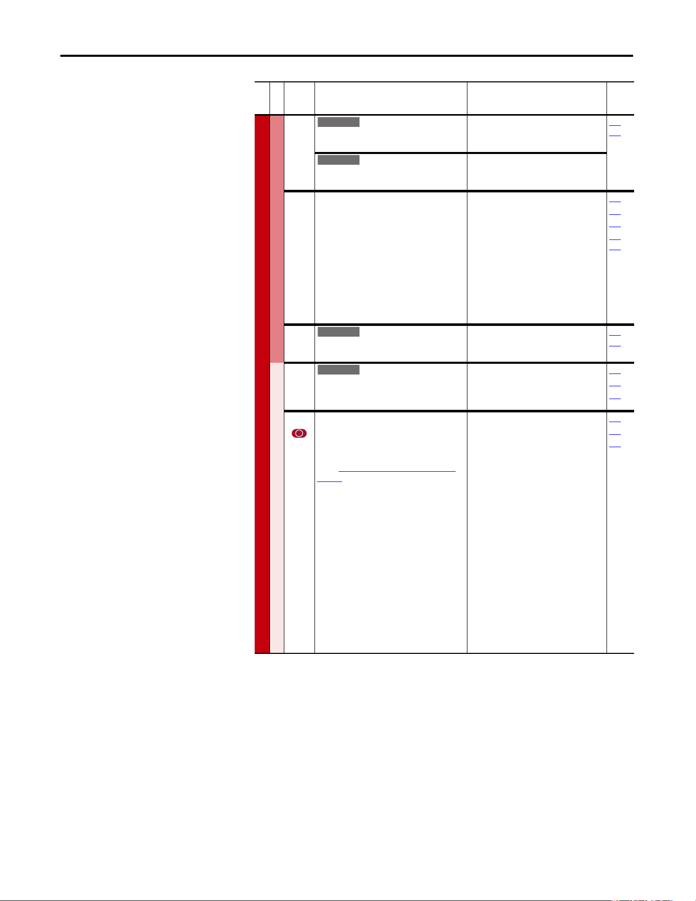
34 Rockwell Automation Publication 20A-UM001P-EN-P - February 2018
Chapter 1 Programming and Parameters
SPEED COMMAND (file C)
Discrete Speeds
100 [Jog Speed]
Sets the output frequency when a jog
command is issued.
Default:
Min/Max:
Units:
10.0 Hz
±[Maximum Speed]
0.1 Hz
361…
366
[Jog Speed 1]
Sets the output frequency when Jog Speed 1 is
selected.
Default:
Min/Max:
Units:
10.0 Hz
±[Maximum Speed]
0.1 Hz
101
102
103
104
105
106
107
[Preset Speed 1]
[Preset Speed 2]
[Preset Speed 3]
[Preset Speed 4]
[Preset Speed 5]
[Preset Speed 6]
[Preset Speed 7]
Provides an internal fixed speed command
value. In bipolar mode direction is commanded
by the sign of the reference.
Default:
Min/Max:
Units:
5.0 Hz
10.0 Hz
20.0 Hz
30.0 Hz
40.0 Hz
50.0 Hz
60.0 Hz
±[Maximum Speed]
0.1 Hz
090
093
213
361…
366
108 [Jog Speed 2]
Sets the output frequency when Jog Speed 2 is
selected.
Default:
Min/Max:
Units:
10.0 Hz
±[Maximum Speed]
0.1 Hz
361…
366
Speed Trim
116 [Trim % Setpoint]
Adds or subtracts a percentage of the speed
reference or maximum speed. Dependent on
the setting of [Trim Out Select], parameter 118.
Default:
Min/Max:
Units:
0.00%
±200.00%
0.01%
090
093
117
117 [Trim In Select]
Specifies the analog input signal to use as a
trim input.
(1)
See External and Internal Connections on
page 93 for DPI port locations.
Default:
Options:
2
1
2
3…7
8
9
10
11
12
13
14
15
16
17
18
19
20
21
22
23
24
25
26
“Analog In 2”
“Analog In 1”
“Analog In 2”
“Reserved”
“Encoder”
“MOP Level”
“Reserved”
“Preset Spd1”
“Preset Spd2”
“Preset Spd3”
“Preset Spd4”
“Preset Spd5”
“Preset Spd6”
“Preset Spd7”
“DPI Port 1”
(1)
“DPI Port 2”
(1)
“DPI Port 3”
(1)
“Reserved”
“DPI Port 5”
(1)
“Reserved”
“Reserved”
“Scale Block1”
“Scale Block2”
090
093
116
File C
Group
No.
Parameter Name and Description
(1)
Values
Related
Standard
E C
E C
E C
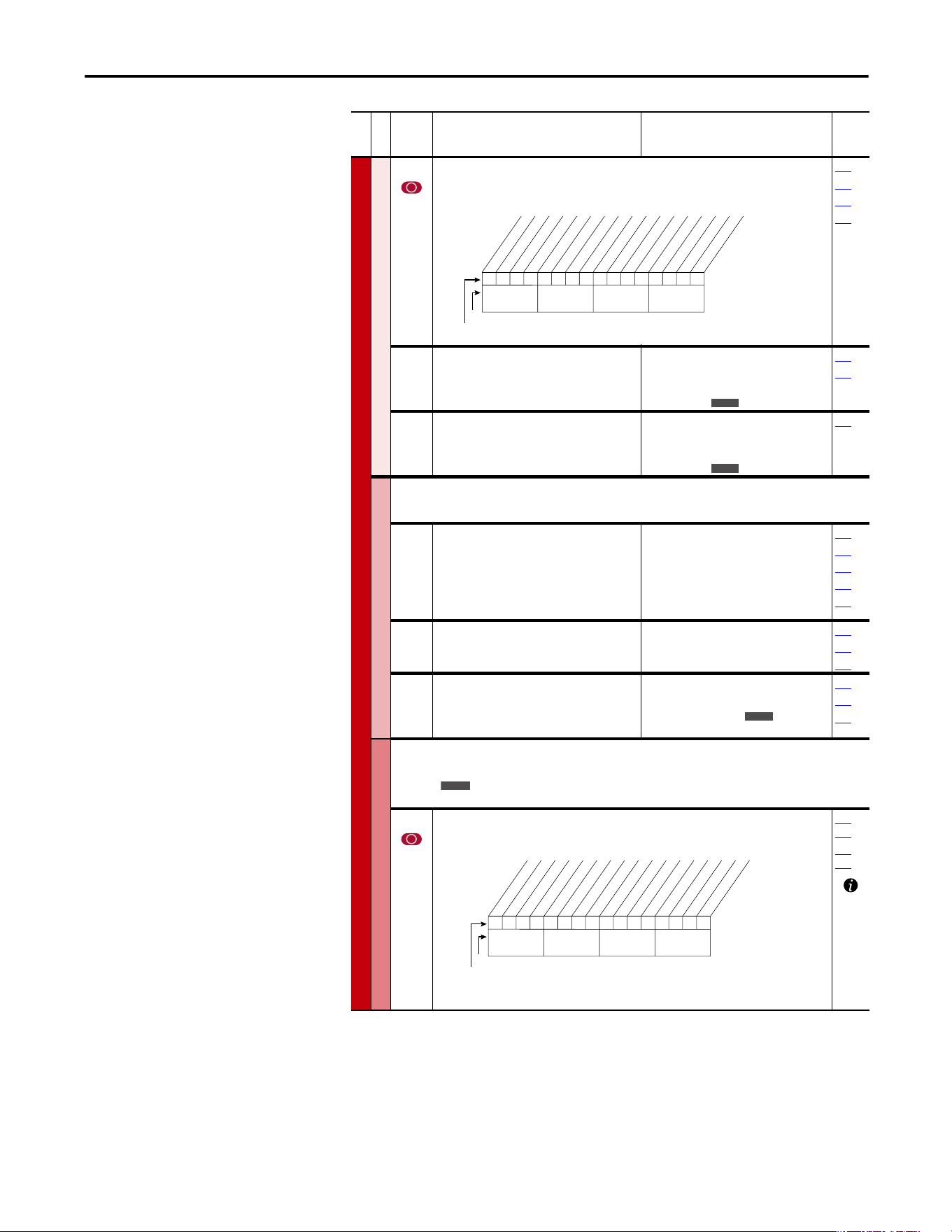
Rockwell Automation Publication 20A-UM001P-EN-P - February 2018 35
Programming and Parameters Chapter 1
SPEED COMMAND (file C)
Speed Trim
118 [Trim Out Select]
Specifies the speed references to be trimmed. To apply negative trim, P190 [Direction Mode]
must be set to 1 “Bipolar.”
117
119
120
190
119 [Trim Hi]
Scales the upper value of the [Trim In Select]
selection when the source is an analog input.
Default:
Min/Max:
Units:
60.0 Hz
±[Maximum Speed]
0.1 Hz
1%
082
117
120 [Trim Lo]
Scales the lower value of the [Trim In Select]
selection when the source is an analog input.
Default:
Min/Max:
Units:
0.0 Hz
±[Maximum Speed]
0.1 Hz
1%
117
Slip Comp
Important: Parameters in the Slip Comp Group are used to enable and tune the Slip
Compensation Regulator. For the Slip Compensation Regulator to control drive operation, set
parameter 080 to 1 “Slip Comp”.
121 [Slip RPM @ FLA]
Sets the amount of compensation to drive
output at motor FLA.
If the value of parameter 061 [Autotune] = 3
“Calculate” changes made to this parameter are
not accepted.
Default:
Min/Max:
Units:
Based on [Motor NP RPM]
0.0/1200.0 rpm
0.1 rpm
044
061
080
122
123
122 [Slip Comp Gain]
Sets the response time of slip compensation.
Default:
Min/Max:
Units:
40.0
1.0/100.0
0.1
080
121
122
123 [Slip RPM Meter]
Displays the present amount of adjustment
being applied as slip compensation.
Default:
Min/Max:
Units:
Read Only
0.0/300.0 rpm
±300.0 rpm
0.1 rpm
080
121
122
Process PI
Important: Parameters in the Process PI Group are used to enable and tune the PI Loop.
For the PI Loop to control drive operation, set parameter 080 to 2 “Process PI”.
124 [PI Configuration]
Sets configuration of the PI regulator.
124
…
138
140…
143
File C
Group
No.
Parameter Name and Description
(1)
Values
Related
00x 0xxxxxxxxxxxx
10 01234567891112131415
1 =Trimmed
0 =Not Trimmed
x =Reserved
Bit #
* Enhanced Control Option Only.Factory Default Bit Values
Trim Ref A
Trim Ref B
Add or % *
Nibble 1Nibble 2Nibble 3Nibble 4
E C
E C
E C
Standard
0000000000xxxxxx
10 01234567891112131415
1 =Enabled
0 =Disabled
x =Reserved
Bit #
Factory Default Bit Values
Excl Mode
Invert Error
Preload Mode
Ramp Ref
Zero Clamp
Feedbak Sqrt
Stop Mode
(1)
Anti-Wind Up
(1)
Torque Trim
(2)
% of Ref
(2)
Nibble 1Nibble 2Nibble 3Nibble 4
(1)
Enhanced firmware 1.001 & later.
(2)
Enhanced firmware 2.001 & later.
36 Rockwell Automation Publication 20A-UM001P-EN-P - February 2018
Chapter 1 Programming and Parameters
SPEED COMMAND (file C)
Process PI
125 [PI Control]
Controls the PI regulator.
080
361…
366
126 [PI Reference Sel]
Selects the source of the PI reference.
(1)
Only Enhanced Control Drives.
Default:
Options:
0“PI Setpoint”
See Table
124…
138
460
127 [PI Setpoint]
Provides an internal fixed value for process
setpoint when [PI Reference Sel] is set to “PI
Setpoint.”
Default:
Min/Max:
Units:
50.00%
±100.00% of Maximum Process
Value
0.01%
124…
138
128 [PI Feedback Sel]
Selects the source of the PI reference.
Default:
Options:
2“Analog In 2”
See
P126 [PI Reference Sel]
.
124…
138
462
463
129 [PI Integral Time]
Time that is required for the integral
component to reach 100% of [PI Error Meter].
Not functional when the PI Hold bit of [PI
Control] = “1” (enabled). A value of zero
disables this parameter
Default:
Min/Max:
Units:
2.00 s
0.00/100.00 s
0.01 s
124…
138
130 [PI Prop Gain]
Sets the value for the PI proportional
component.
PI Error PI Prop Gain = PI Output
Default:
Min/Max:
Units:
1.00
0.00/100.00
0.01
124…
138
131 [PI Lower Limit]
Sets the lower limit of the PI output.
Default:
Min/Max:
Units:
–[Maximum Freq]
–100%
±400.0 Hz
±800%
0.1 Hz
0.1%
124…
138
File C
Group
No.
Parameter Name and Description
(1)
Values
Related
00x 0xxxxxxxxxxxx
10 01234567891112131415
1 =Enabled
0 =Disabled
x =Reserved
Bit #
Factory Default Bit Values
PI Enable
PI Hold
PI Reset
Nibble 1Nibble 2Nibble 3Nibble 4
Options P462 [PI Feedback Hi] P463 [PI Feedback Lo]
0
1
2
3…7
8
9
10
11…17
18…20
21
22
23, 24
25
26
27…29
30
31
32
33
“Setpoint”
“Analog In 1”
“Analog In 2”
“Reserved”
“Encoder”
“MOP Level”
“Master Ref”
“Preset Spd1…7”
“DPI Port 1…3”
“Reserved”
“DPI Port 5”
“Reserved”
“Scale Block1”
“Scale Block2”
“Reserved”
“HighRes Ref”
(1)
“CommandedTrq”
(2)
“Torque Est”
(2)
“Torque Amps”
(2)
+100
P322 [Analog In1 Hi]
P325 [Analog In2 Hi]
+P55 [Maximum Freq]
+P55 [Maximum Freq]
+P55 [Maximum Freq]
+P55 [Maximum Freq]
+32767
+32767
P477 [Scale1 In Hi]
P483 [Scale2 In Hi]
+32767 x 2
16
P436 [Pos Torque Limit]
P436 [Pos Torque Limit]
+P28 [Rated Amps]
-100
P323 [Analog In1 Lo]
P326 [Analog In2 Lo]
-P55 [Maximum Freq]
-P55 [Maximum Freq]
-P55 [Maximum Freq]
-P55 [Maximum Freq]
-32676
-32676
P478 [Scale1 In Lo]
P484 [Scale2 In Lo]
-32767 x 2
16
P437 [Neg Torque Limit]
P437 [Neg Torque Limit]
-P28 [Rated Amps]
E C
E C
E C
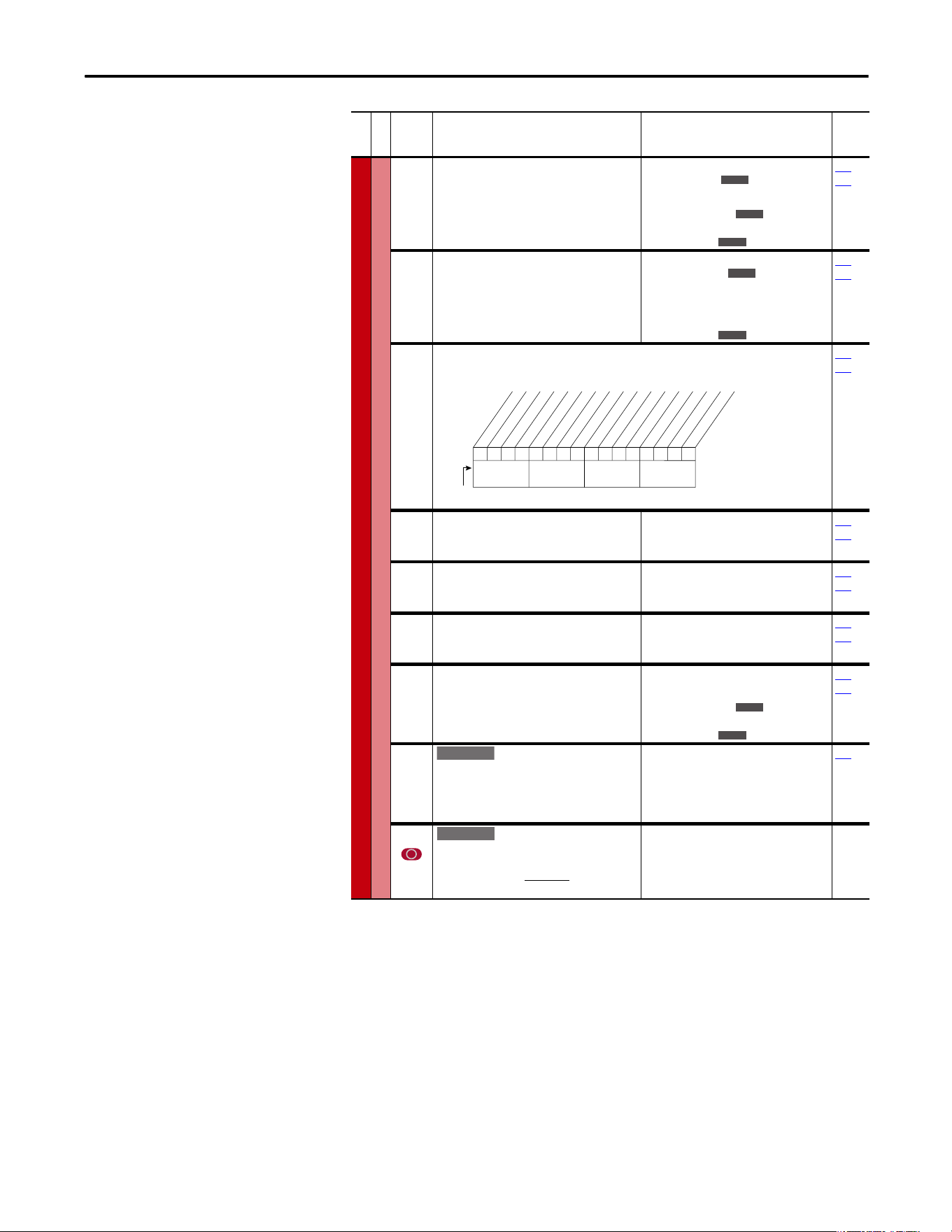
Rockwell Automation Publication 20A-UM001P-EN-P - February 2018 37
Programming and Parameters Chapter 1
SPEED COMMAND (file C)
Process PI
132 [PI Upper Limit]
Sets the upper limit of the PI output.
Default:
Min/Max:
Units:
+[Maximum Freq]
100%
±400.0 Hz
±800.0%
0.1 Hz
0.1%
124…
138
133 [PI Preload]
Sets the value that is used to preload the
integral component on start or enable.
Default:
Min/Max:
Units:
0.0 Hz
100.0%
[PI Lower Limit]/
[PI Upper Limit
0.1 Hz
0.1%
124…
138
134 [PI Status]
Status of the Process PI regulator.
Read Only
124…
138
135 [PI Ref Meter]
Present value of the PI reference signal.
Default:
Min/Max:
Units:
Read Only
±100.00%
0.01%
124…
138
136 [PI Fdback Meter]
Present value of the PI feedback signal.
Default:
Min/Max:
Units:
Read Only
±100.00%
0.01%
124…
138
137 [PI Error Meter]
Present value of the PI error.
Default:
Min/Max:
Units:
Read Only
±100.00%
0.01%
124…
138
138 [PI Output Meter]
Present value of the PI output.
Default:
Min/Max:
Units:
Read Only
±100.0 Hz
±800.0%
0.1 Hz
0.1%
124…
138
139 [PI BW Filter]
Firmware revision 2.001 and later – Provides
filter for Process PI error signal. The output of
this filter is displayed in [PI Error Meter]. Zero
disables the filter.
Default:
Min/Max:
Units:
0.0 R/s
0.0/240.0 R/s
0.1 R/s
137
459 [PI Deriv Time]
Refer to formula below:
Default:
Min/Max:
Units:
0.00 s
0.00/100.00 s
0.01 s
File C
Group
No.
Parameter Name and Description
(1)
Values
Related
E C
E C
E C
E C
E C
0000xxxxxxxxxxxx
10 01234567891112131415
1 =Condition True
0 =Condition False
x =Reserved
Bit #
PI Enabled
PI Hold
PI Reset
PI InLimit
Nibble 1Nibble 2Nibble 3Nibble 4
E C
E C
E C v2
E C v2
d
PI Error
(%)
d
t
(Sec)
PI
Out
= KD (Sec) x
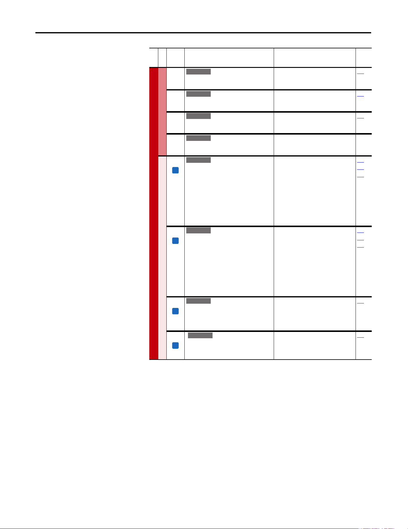
38 Rockwell Automation Publication 20A-UM001P-EN-P - February 2018
Chapter 1 Programming and Parameters
SPEED COMMAND (file C)
Process PI
460 [PI Reference Hi]
Scales the upper value of [PI Reference Sel] of
the source.
Default:
Min/Max:
Units:
100.0%
±100.0%
0.1%
126
461 [PI Reference Lo]
Scales the lower value of [PI Reference Sel]
of the source.
Default:
Min/Max:
Units:
–100.0%
±100.0%
0.1%
126
462 [PI Feedback Hi]
Scales the upper value of [PI Feedback] of
the source.
Default:
Min/Max:
Units:
100.0%
±100.0%
0.1%
128
463 [PI Feedback Lo]
Scales the lower value of [PI Feedback] of
the source.
Default:
Min/Max:
Units:
0.0%
±100.0%
0.1%
Speed Regulator
445 [Ki Speed Loop]
Controls the integral error gain of the speed
regulator. The drive automatically adjusts P445
[Ki Speed Loop] when a non-zero value is
entered for P449 [Speed Desired BW] or an
autotune is performed. Typically, manual
adjustment of this parameter is needed only if
system inertia cannot be determined through
an autotune. P449 [Speed Desired BW] is set to
“0” when a manual adjustment is made to this
parameter.
Default:
Min/Max:
Units:
7.8
0.0/4000.0
0.1
053
449
450
446 [Kp Speed Loop]
Controls the proportional error gain of the
speed regulator. The drive automatically
adjusts P446 [Kp Speed Loop] when a non-zero
value is entered for P449 [Speed Desired BW] or
an auto-tune is performed. Typically, manual
adjustment of this parameter is needed only if
system inertia cannot be determined through
an autotune. P449 [Speed Desired BW] is set to
“0” when a manual adjustment is made to this
parameter.
Default:
Min/Max:
Units:
6.3
0.0/200.0
0.1
053
449
450
447 [Kf Speed Loop]
Controls the feed forward gain of the speed
regulator. Setting the Kf gain greater than zero
reduces speed feedback overshoot in response
to a step change in speed reference.
Default:
Min/Max:
Units:
0.0
0.0/0.5
0.1
053
448 [Spd Err Filt BW]
Sets the bandwidth of a speed error filter that is
used in FVC Vector mode. A setting of 0.0
disables the filter.
Default:
Min/Max:
Units:
200.0 R/s
0.0/2000.0 R/s
0.1 R/s
053
File C
Group
No.
Parameter Name and Description
(1)
Values
Related
E C
E C
E C
E C
FV
E C v2
FV
E C v2
FV
E C v2
FV
E C v3
Rockwell Automation Publication 20A-UM001P-EN-P - February 2018 39
Programming and Parameters Chapter 1
SPEED COMMAND (file C)
Speed Regulator
449 [Speed Desired BW]
Sets the speed loop bandwidth and determines
the dynamic behavior of the speed loop. As
bandwidth increases, the speed loop becomes
more responsive and can track a faster
changing speed reference.
Adjusting this parameter causes the drive to
calculate and change P445 [Ki Speed Loop] and
P446 [Kp Speed Loop] gains.
Default:
Min/Max:
Units:
0.0 Radians/Sec
0.0/250.0 Radians/Sec
0.1 Radians/Sec
053
067
445
446
450 [Total Inertia]
Represents the time in seconds, for a motor
that is coupled to a load to accelerate from zero
to base speed, at rated motor torque. The drive
calculates Total Inertia during the autotune
inertia procedure.
Adjusting this parameter causes the drive to
calculate and change P445 [Ki Speed Loop] and
P446 [Kp Speed Loop] gains.
Default:
Min/Max:
Units:
0.10 s
0.01/600.0 s
0.01 s
053
067
445
446
449
451 [Speed Loop Meter]
Value of the speed regulator output. When in
FVC mode, units are in percent.
Default:
Min/Max:
Units:
Read Only
±800.0%/Hz
0.1%/Hz
053
121
(1) See page 13 for Symbol Descriptions.
File C
Group
No.
Parameter Name and Description
(1)
Values
Related
FV
E C v2
FV
E C v2
FV
E C v2
40 Rockwell Automation Publication 20A-UM001P-EN-P - February 2018
Chapter 1 Programming and Parameters
Dynamic Control File (File D)
File D
Group
No.
Parameter Name and Description
(1)
Values
Related
DYNAMIC CONTROL (file D)
Ramp Rates
140
141
[Accel Time 1]
[Accel Time 2]
Sets the rate of accel for all speed increases.
Default:
Min/Max:
Units:
10.0 s
10.0 s
0.0/3600.0 s
0.1 s
142
143
146
361…
366
142
143
[Decel Time 1]
[Decel Time 2]
Sets the rate of decel for all speed decreases.
Default:
Min/Max:
Units:
10.0 s
10.0 s
0.0/3600.0 s
0.1 s
140
141
146
361…
366
146 [S Curve %]
Sets the percentage of accel or decel time that is
applied to the ramp as S Curve. Time is added,
1/2 at the beginning and
1/2 at the end of the ramp.
Default:
Min/Max:
Units:
0.0%
0.0/100.0%
0.1%
056
140…
143
Load Limits
147 [Current Lmt Sel]
Selects the source for the adjustment of current
limit (for example, parameter, analog input,
and so on).
Default:
Options:
0
0
1
2
“Cur Lim Val”
“Cur Lim Val”
“Analog In 1”
“Analog In 2”
146
148
149
148 [Current Lmt Val]
Defines the current limit value when [Current
Lmt Sel] = “Cur Lim Val.”
Default:
Min/Max:
Units:
[Rated Amps] 1.5
(Equation approximates default
value.)
Drive Rating Based
0.1 Amps
028
147
149
149 [Current Lmt Gain]
Sets the responsiveness of the current limit.
Default:
Min/Max:
Units:
250
0/5000
1
147
148
150 [Drive OL Mode]
Selects the drive’s response to increasing drive
temperature.
Default:
Options:
3
0
1
2
3
“Both–PWM 1st”
“Disabled”
“Reduce CLim”
“Reduce PWM”
“Both–PWM 1st”
219
151 [PWM Frequency]
Sets the carrier frequency for the PWM output.
Drive derating can occur at higher carrier
frequencies. For derating information, refer to
the PowerFlex Reference Manual, publication
PFLEX-RM001
.
Default:
Min/Max:
Units:
4 kHz
2, 3, 4, 5, 6, 7, 8, 9, 10 kHz
2, 4, 8, 12 kHz
(1)
1 kHz
(1)
Only Frames A…D.
Max Speed
Accel Time
Accel Rate
=
Max Speed
Decel Time
Decel Rate
=
E C
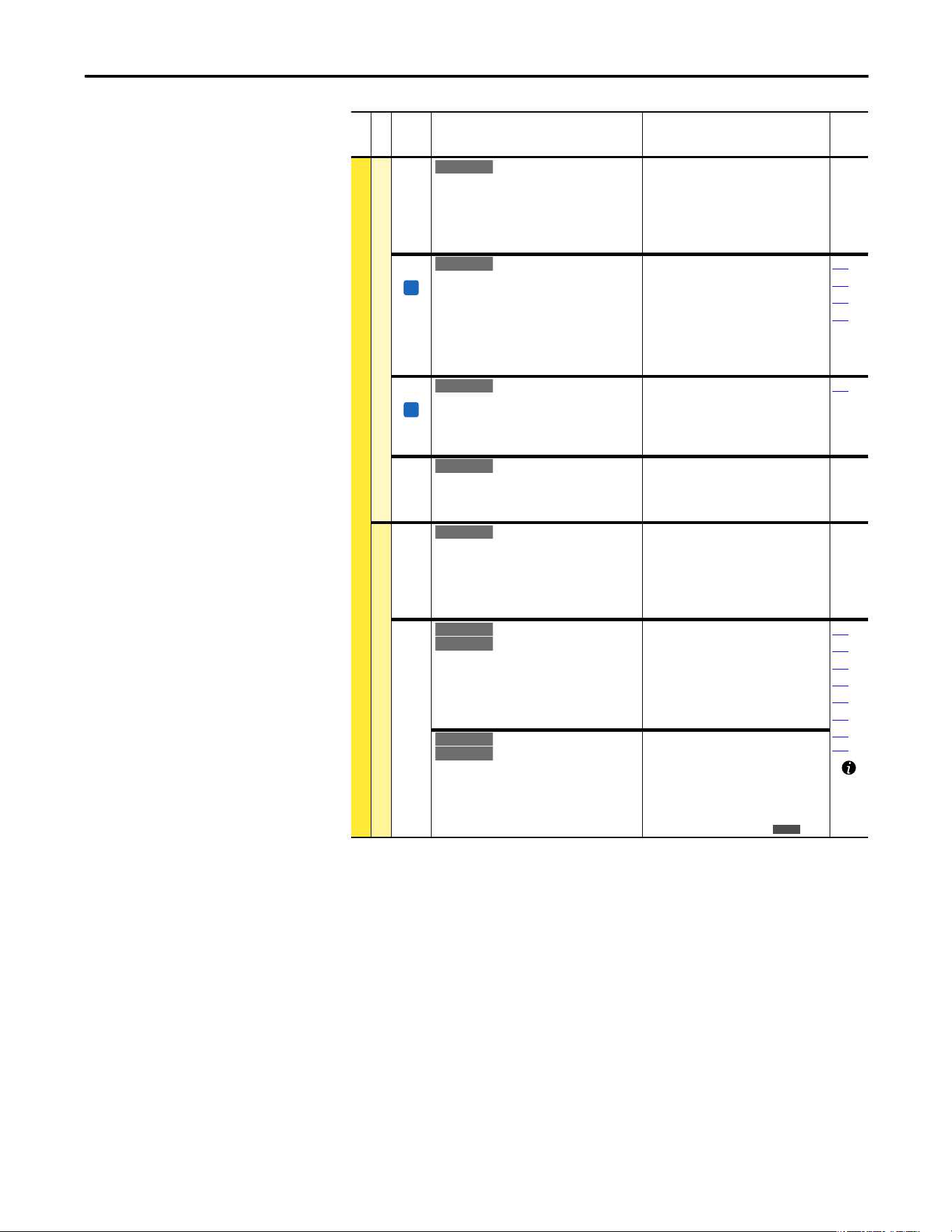
Rockwell Automation Publication 20A-UM001P-EN-P - February 2018 41
Programming and Parameters Chapter 1
DYNAMIC CONTROL (file D)
Load Limits
152 [Droop RPM @ FLA]
Selects amount of droop that the speed
reference is reduced when at full load torque.
Zero disables the droop function.
Setting parameter 080 to 0 is recommended
when you are using the Droop function.
Default:
Min/Max:
Units:
0.0 rpm
0.0/200.0 rpm
0.1 rpm
153 [Regen Power Lim]
Sets the maximum power limit transfer from
the motor to the DC bus. When you are using an
external dynamic brake, set this parameter to its
minimum
(–800.0%) value. Overvoltage trips can occur if
set too negative and the connected brake is
unable to dissipate the energy.
Default:
Min/Max:
Units:
–50.0%
–800.0/0.0%
0.1%
053
161
162
163
154 [Current Rate Lim]
Sets the largest rate of change for the current
reference signal. This number is scaled in
percent of maximum motor current every 250
microseconds.
Default:
Min/Max:
Units:
400.0%
1.0/800.0%
0.1%
053
189 [Shear Pin Time]
Sets the time that the drive is at or above
current limit before a fault occurs. Zero disables
this feature.
Default:
Min/Max:
Units:
0.0 s
0.0/30.0 s
0.1 s
Stop/Brake Modes
145 [DB While Stopped]
Enables/disables dynamic brake operation.
Disabled = DB operates only when the drive is
running.
Enable = DB operates whenever the drive is
energized.
Default:
Options:
0
0
1
“Disabled”
“Disabled”
“Enabled”
155
156
[Stop Mode A]
[Stop Mode B]
Active stop mode. [Stop Mode A] is active unless
[Stop Mode B] is selected by digital inputs that
are programmed for “Stop Mode B.”
(1)
When you are using options 1 or 2, refer to
the Attention statements at [DC Brake Level].
Default:
Default:
Options:
1
0
0
1
2
3
“Ramp”
“Coast”
“Coast”
“Ramp”
(1)
“Ramp to Hold”
(1)
“DC Brake”
157
158
159
161
163
168
361…
366
[Stop/Brk Mode A]
[Stop/Brk Mode B]
See description above.
Default:
Default:
Options:
1
0
0
1
2
3
4
“Ramp”
“Coast”
“Coast”
“Ramp”
(1)
“Ramp to Hold”
(1)
“DC Brake”
“Fast Brake”
File D
Group
No.
Parameter Name and Description
(1)
Values
Related
E C v2
FV
E C v2
FV
E C v2
E C
E C
Standard
Standard
E C v2
E C v2
E C v3
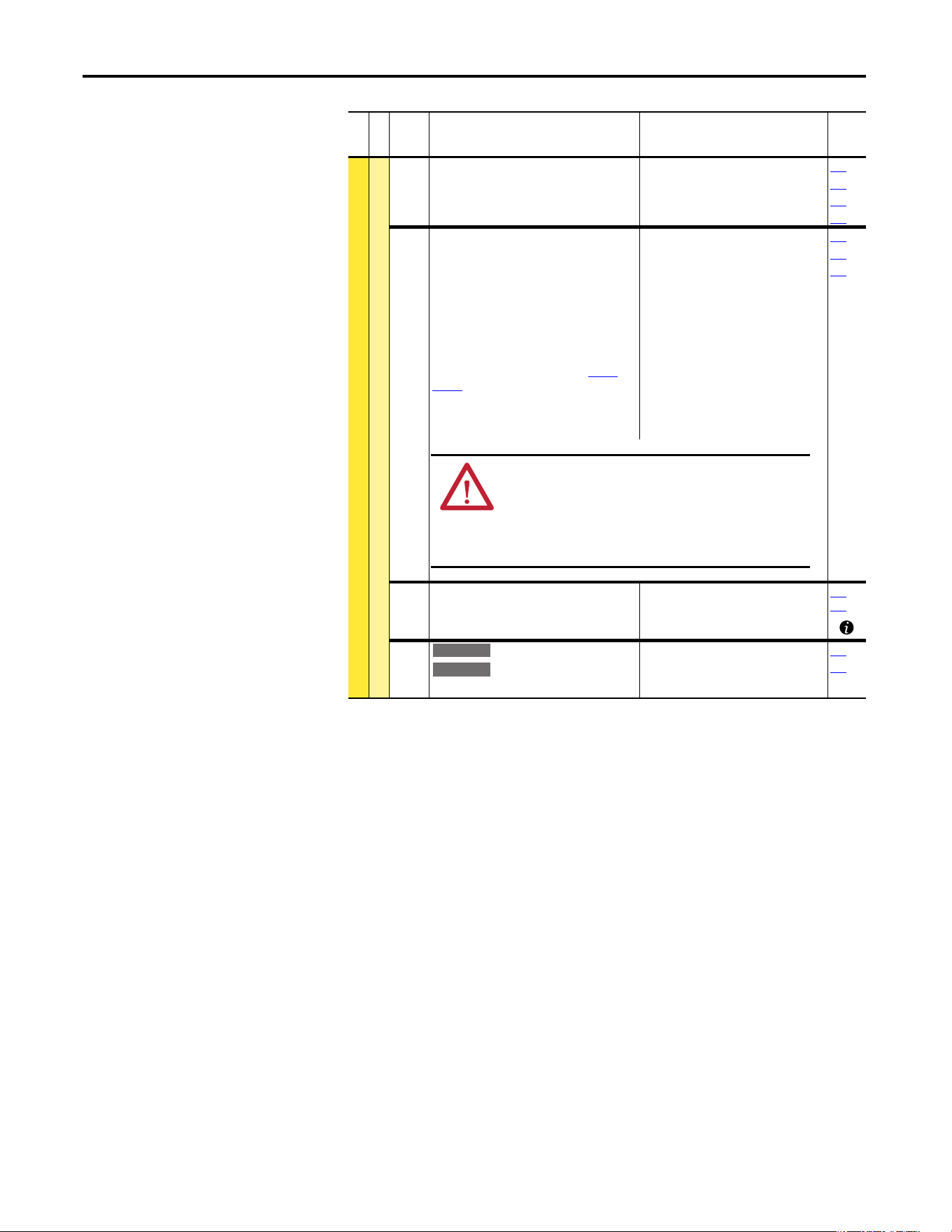
42 Rockwell Automation Publication 20A-UM001P-EN-P - February 2018
Chapter 1 Programming and Parameters
DYNAMIC CONTROL (file D)
Stop/Brake Modes
157 [DC Brake Lvl Sel]
Selects the source for [DC Brake Level].
Default:
Options:
0
0
1
2
“DC Brake Lvl”
“DC Brake Lvl”
“Analog In 1”
“Analog In 2”
155
156
158
159
158 [DC Brake Level]
Defines the DC brake current level that is
injected into the motor when “DC Brake” is
selected as a stop mode.
The DC braking voltage that is used in this
function is created by a PWM algorithm and can
fail to generate the smooth holding force that is
needed for some applications. Refer to the
PowerFlex 70 and 700 Adjustable Frequency AC
Drive Reference Manual, publication PFLEX-
RM001.
Important: Frame E drives can be limited to
less than 150% depending on the setting of
parameter 151 [PWM Frequency].
Default:
Min/Max:
Units:
[Rated Amps]
0/[Rated Amps] 1.5
(Equation yields approximate
maximum value.)
0.1 Amps
155
156
157
159 [DC Brake Time]
Sets the amount of time DC brake current is
“injected” into the motor.
Default:
Min/Max:
Units:
0.0 s
0.0/90.0 s
0.1 s
155…
158
160 [Bus Reg Gain]
[Bus Reg Ki]
Sets the responsiveness of the bus regulator.
Default:
Min/Max:
Units:
450
0/5000
1
161
162
File D
Group
No.
Parameter Name and Description
(1)
Values
Related
ATTENTION: If a hazard of injury due to movement of
equipment or material exists, an auxiliary mechanical braking
device must be used.
ATTENTION: Do not use this feature with synchronous or
permanent magnet motors. Motors can be demagnetized during
braking.
Standard
E C
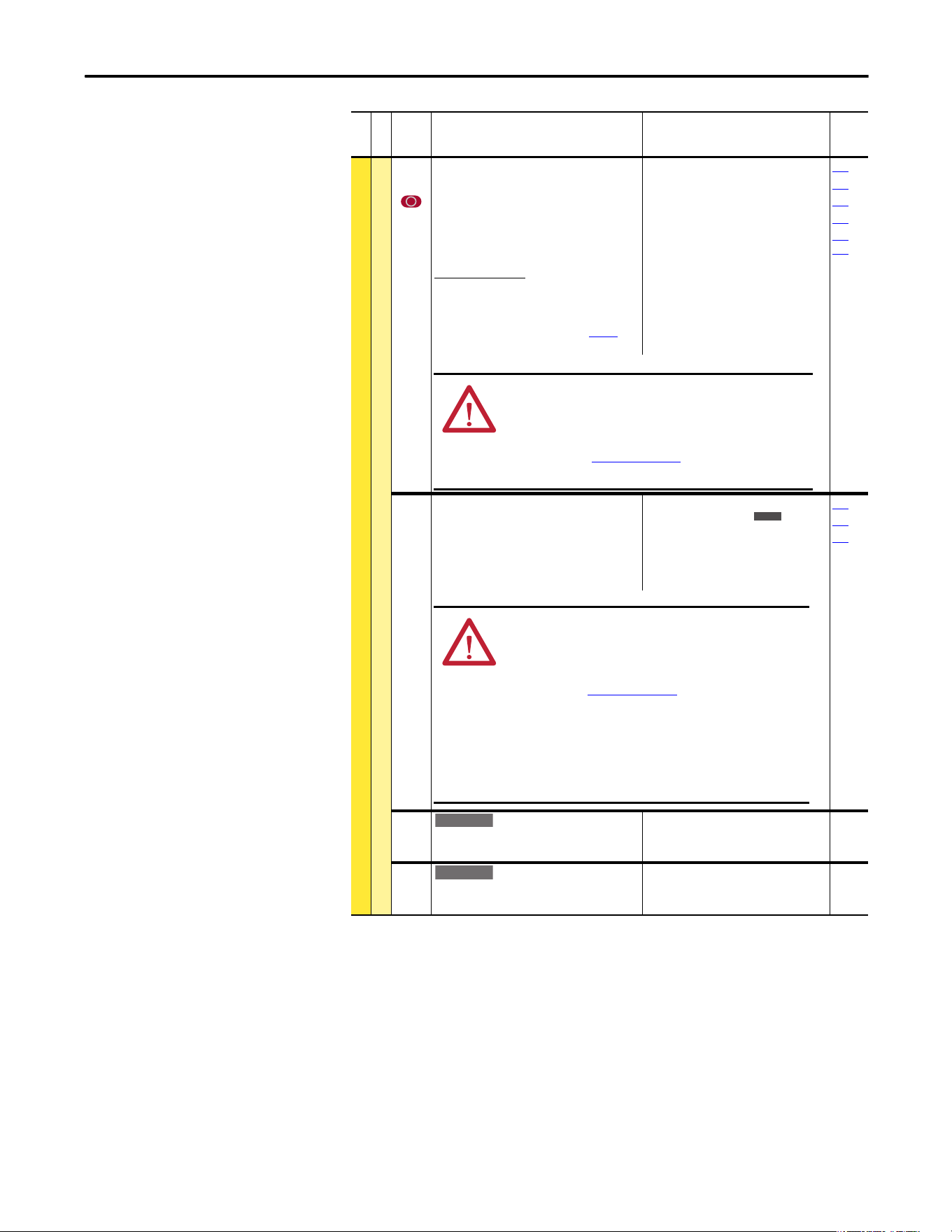
Rockwell Automation Publication 20A-UM001P-EN-P - February 2018 43
Programming and Parameters Chapter 1
DYNAMIC CONTROL (file D)
Stop/Brake Modes
161
162
[Bus Reg Mode A]
[Bus Reg Mode B]
Active bus regulation mode. Choices are
dynamic brake, frequency adjust or both.
Sequence is determined by programmed value
or digital input that is programmed for “Bus Reg
Md B.”
Dynamic Brake Setup
If a dynamic brake resistor is connected to the
drive, both these parameters must be set to
either option 2, 3 or 4.
Refer to the Attention statement on page 9 for
important information on bus regulation.
Default:
Options:
1
4
0
1
2
3
4
“Adjust Freq”
“Both-Frq 1st”
“Disabled”
“Adjust Freq”
“Dynamic Brak”
“Both-DB 1st”
“Both-Frq 1st”
155
156
160
163
361…
366
163 [DB Resistor Type]
Selects whether the internal or an external DB
resistor used.
If a dynamic brake resistor is connected to the
drive, P161/162 [Bus Reg Mode x], A, B or Both
(if used), must be set to either option 2, 3 or 4.
Default:
Options:
0
2
0
1
2
“Internal Res”
“None”
“Internal Res”
“External Res”
“None”
161
162
166
164 [Bus Reg Kp]
Proportional gain for the bus regulator. Used to
adjust regulator response.
Default:
Min/Max:
Units:
1500
0/10000
1
165 [Bus Reg Kd]
Derivative gain for the bus regulator. Used to
control regulator overshoot.
Default:
Min/Max:
Units:
1000
0/10000
1
File D
Group
No.
Parameter Name and Description
(1)
Values
Related
ATTENTI ON: The drive does not offer protection for externally
mounted brake resistors. A risk of fire exists if external braking
resistors are not protected. External resistor packages must be
self-protected. from over temperature or the protective circuit
that is shown in Figure 1 on page 100
(or equivalent) must be
supplied.
E C
ATTENTION: The drive does not offer protection for externally
mounted brake resistors. A risk of fire exists if external braking
resistors are not protected. External resistor packages must be
self-protected from over temperature or the protective circuit
that is shown in Figure 1 on page 100
, or equivalent, must be
supplied.
ATTENTION: Equipment damage can result if a drive mounted
(internal) resistor is installed and this parameter is set to
“External Res.” Thermal protection for the internal resistor is
disabled, resulting in possible device damage.
E C
E C
44 Rockwell Automation Publication 20A-UM001P-EN-P - February 2018
Chapter 1 Programming and Parameters
DYNAMIC CONTROL (file D)
Stop/Brake Modes
166 [Flux Braking]
Set to use an increase in the motor flux current
to increase the motor losses, and enables a
faster deceleration time when a chopper brake
or regenerative capability is not available. Can
be used as a stopping or fast deceleration
method.
For more information about applying this mode
of operation, see Stop Modes
on page 103.
Default:
Options:
0
0
1
“Disabled”
“Disabled”
“Enabled”
Restart Modes
167 [Powerup Delay]
Defines the programmed delay time, in seconds,
before a start command is accepted after a
powerup.
Default:
Min/Max:
Units:
0.0 s
0.0/30.0 s
0.1 s
168 [Start At Powerup]
Enables/disables a feature to issue a Start or
Run command and automatically resume
running at commanded speed after drive input
power is restored. Requires a digital input that is
configured for Run or Start and a valid start
contact.
Default:
Options:
0
0
1
“Disabled”
“Disabled”
“Enabled”
167
169
174
361…
366
File D
Group
No.
Parameter Name and Description
(1)
Values
Related
E C v2
E C
ATTENTI ON: Equipment damage and/or personal injury can
result if this parameter is used in an inappropriate application.
Do not use this function without considering applicable local,
national, and international codes, standards, regulations or
industry guidelines.
Rockwell Automation Publication 20A-UM001P-EN-P - February 2018 45
Programming and Parameters Chapter 1
DYNAMIC CONTROL (file D)
Restart Modes
169 [Flying Start En]
Enables/disables the function that reconnects to
a spinning motor at actual rpm when a start
command is issued.
Default:
Options:
0
0
1
“Disabled”
“Disabled”
“Enabled”
170
170 [Flying StartGain]
Sets the response of the flying start function.
Default:
Min/Max:
Units:
4000
20/32767
1
169
174 [Auto Rstrt Tries]
Sets the maximum number of times the drive
attempts to reset a fault and restart. Refer to the
PowerFlex Reference Manual, publication
PFLEX-RM004 for additional information.
Default:
Min/Max:
Units:
0
0/9
1
175
175 [Auto Rstrt Delay]
Sets the time between restart attempts when
[Auto Rstrt Tries] is set to a value other than
zero.
The HIM display shows AutoRst X,YY during the
restart delay. Where X is the number of restarts
that are left and YY is the time that is left before
restart. For delay times of 99 seconds or less, YY
displays the seconds remaining before restart.
For delay times greater than 99 seconds, YY
changes to the percent of delay time remaining
before restart.
Default:
Min/Max:
Units:
1.0 s
0.5/6000.0 s
0.1 s
174
File D
Group
No.
Parameter Name and Description
(1)
Values
Related
ATTENTION: Equipment damage and/or personal injury can
result if this parameter is used in an inappropriate application.
Do not use this function without considering applicable local,
national, and international codes, standards, regulations or
industry guidelines.
Description Example Screen
Restarts Remaining = 8
Delay Time = 93 seconds
F-> AutoRst 8,93 Auto
F2
Auxiliary Input
Time Since Fault
00000:00:31
46 Rockwell Automation Publication 20A-UM001P-EN-P - February 2018
Chapter 1 Programming and Parameters
DYNAMIC CONTROL (file D)
Restart Modes
178 [Sleep Wake Mode]
Enables/disables the Sleep/Wake function.
Important: When enabled, the following
conditions must be met:
· A proper value must be programmed for [Sleep
Level] and [Wake Level].
· A speed reference must be selected in [Speed Ref
A Sel].
· At least one of the following must be
programmed (and input closed) in [Digital Inx
Sel]; “Enable,” “Stop=CF,” “Run,” “Run Forward,”
“Run Reverse.”
Default:
Options:
0
0
1
2
“Disabled”
“Disabled”
“Direct” (Enabled)
“Invert” (Enabled)
(7)
179…
183
(1)
When power is cycled, if all of the above conditions are present after power is restored, a restart
occurs.
(2)
If all of the above conditions are present when [Sleep-Wake Mode] is “enabled,” the drive starts.
(3)
The active speed reference is determined as explained in Speed Reference Control on page 110.
The Sleep/Wake function and the speed reference can be assigned to the same input.
(4)
Command must be issued from HIM, TB, or network.
(5)
Run Command must be cycled.
(6)
Signal does not need to be greater than wake level.
(7)
Enhanced firmware revision 2.001 and later. For Invert function, refer to [Analog In x Loss].
File D
Group
No.
Parameter Name and Description
(1)
Values
Related
E C v2
ATTENTION: Enabling the Sleep-Wake function can cause unexpected
machine operation during the Wake mode. Equipment damage and/or
personal injury can result if this parameter is used in an inappropriate
application. Do Not use this function without considering the
information below and in Appendix C. In addition, all applicable local,
national and international codes, standards, regulations or industry
guidelines must be considered.
!
Conditions Required to Start Drive
(1)(2)(3)
Input After Powerup After a Drive Fault After a Stop
Command
Reset by Stop-CF,
HIM or TB
Reset by
Clear Faults
(TB)
HIM or TB
Stop Stop Closed
Wake Signal
Stop Closed
Wake Signal
New Start or Run
Cmd.
(4)
Stop Closed
Wake Signal
Stop Closed
Direct Mode
Analog Sig. > Sleep
Level
(6)
Invert Mode
Analog Sig. < Sleep
Level
(6)
New Start or Run
Cmd.
(4)
Rockwell Automation Publication 20A-UM001P-EN-P - February 2018 47
Programming and Parameters Chapter 1
Restart Modes
179 [Sleep Wake Ref]
Selects the source of the input controlling the
Sleep-Wake function.
Default:
Options:
2
1
2
“Analog In 2”
“Analog In 1”
“Analog In 2”
178
180
183
320…
327
180 [Wake Level]
Defines the analog input level that starts the
drive.
Default:
Min/Max:
Units:
6.000 mA, 6.000 Volts
[Sleep Level]/20.000 mA [Sleep
Level]/10.000 Volts
0.001 mA
0.001 Volts
178
179
181
183
181 [Wake Time]
Defines the amount of time at or above [Wake
Level] before a Start is issued.
Default:
Min/Max:
Units:
1.0 s
0.0/1000.0 s
0.1 s
178
180
182 [Sleep Level]
Defines the analog input level that stops the
drive.
Default:
Min/Max:
Units:
5.000 mA, 5.000 Volts
4.000 mA/[Wake Level]
0.000 Volts/[Wake Level]
0.001 mA
0.001 Volts
178
180
183
183 [Sleep Time]
Defines the amount of time at or below [Sleep
Level] before a Stop is issued.
Default:
Min/Max:
Units:
1.0 s
0.0/1000.0 s
0.1 s
182
DYNAMIC CONTROL (file D)
Power Loss
177 [Gnd Warn Level]
Sets the level where a ground warning fault
occurs. Configure with [Alarm Config 1].
Default:
Min/Max:
Units:
3.0 Amps
1.0/5.0 Amps
0.1 Amps
259
184 [Power Loss Mode]
Sets the reaction to a loss of input power. Power
loss is recognized when:
• DC bus voltage is 73% of [DC Bus Memory]
and [Power Loss Mode] is set to “Coast”.
• DC bus voltage is 82% of [DC Bus Memory]
and [Power Loss Mode] is set to “Decel”.
Default:
Options:
0
0
1
2
3
4
5
“Coast”
“Coast”
“Decel”
“Continue”
“Reserved”
“Reserved”
“Decel 2 Stop”
013
185
361…
366
“Coast” = Disable drive and enable the motor to coast.
“Decel” = Decelerate the motor at a rate that regulates the DC Bus until the load’s Kinetic
Energy can no longer power the drive.
“Continue” = Enable the drive to power the motor down to 50% of the nominal DC Bus
voltage.
Refer to the PowerFlex 70EC/700VC Reference Manual, publication PFLEX-RM004
, for
additional information.
185 [Power Loss Time]
Sets the time that the drive remains in power
loss mode before a fault is issued.
Default:
Min/Max:
Units:
0.5 s
0.0/60.0 s
0.1 s
184
187 [Load Loss Level]
Sets the percentage of motor nameplate torque
where a load loss alarm occurs.
Default:
Min/Max:
Units:
200.0%
0.0/800.0%
0.1%
211
259
188 [Load Loss Time]
Sets the time that current is below the level set
in [Load Loss Level] before a fault occurs.
Default:
Min/Max:
Units:
0.0 s
0.0/300.0 s
0.1 s
187
(1) See page 13 for Symbol Descriptions.
File D
Group
No.
Parameter Name and Description
(1)
Values
Related
E C v2
E C v2
E C v2
E C v2
E C v2
E C v2
E C
E C v4
ATTENTION: To guard against drive damage, a minimum line
impedance must be provided to limit inrush current when the
power line recovers. Provide an input impedance equal or
greater than the equivalent of a 5% transformer with a VA rating
6 times the drive’s input VA rating.
E C v2
E C v2
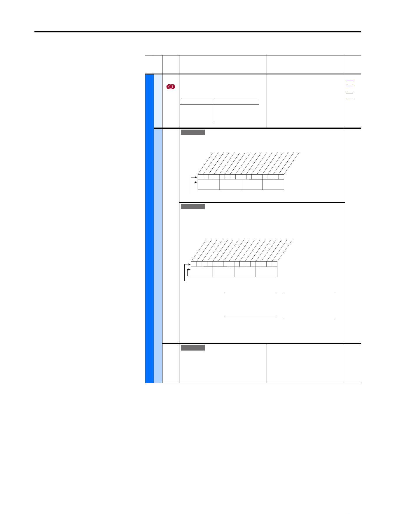
48 Rockwell Automation Publication 20A-UM001P-EN-P - February 2018
Chapter 1 Programming and Parameters
Utility File (File E)
File E
Group
No.
Parameter Name and Description
(1)
Values
Related
UTILITY (file E)
Direction Config
190 [Direction Mode]
Selects the method for changing drive
direction.
Default:
Options:
0
0
1
2
“Unipolar”
“Unipolar”
“Bipolar”
“Reverse Dis”
320…
327
361…
366
HIM Ref Config
192 [Save HIM Ref]
Enables a feature to save the present frequency reference value that is issued by the HIM to
Drive memory on power loss. Value is restored to the HIM on powerup.
[AutoMan Cnfg]
Enables HIM to control only the Speed Reference, or Reference, Start, and Jog in Manual
mode including two-wire control. Also enables a feature to save the preset frequency
reference value that is issued by the HIM to drive memory on power loss. Value is restored to
the HIM on powerup.
193 [Man Ref Preload]
Enables/disables a feature to automatically
load the present “Auto” frequency reference
value into the HIM when “Manual” is selected.
Enables smooth speed transition from “Auto” to
“Manual.”
Default:
Options:
0
0
1
“Disabled”
“Disabled”
“Enabled”
Mode Direction Change
Unipolar Drive Logic
Bipolar Sign of Reference
Reverse Dis Not Changeable
Standard
xxx 1xxxxxxxxxxxx
10 01234567891112131415
1 =Save at Power Down
0 =Do Not Save
x = Reserved
Bit #
Factory Default Bit Values
At Powr Down
Nibble 1Nibble 2Nibble 3Nibble 4
E C
0101xxxxxxxxxxxx
10 01234567891112131415
Bit #
Factory Default Bit Values
Save HIM Ref
Manual Mode
ManRefPrld
HIM Disable
Nibble 1Nibble 2Nibble 3Nibble 4
Save HIM Ref
1 = Saves HIM reference,
Reloads HIM reference at
power-up.
0 = Disabled
ManRefPrld
1 = Preloads auto reference into
HIM upon Auto to Manual
transition.
0 = Disabled
Manual Mode
1 = HIM has exclusive Start &
Jog control in Manual mode.
0 = Disabled
HIM Disable
1 = HIM does not start drive.
0 = HIM starts drive
x = Reserved
Standard
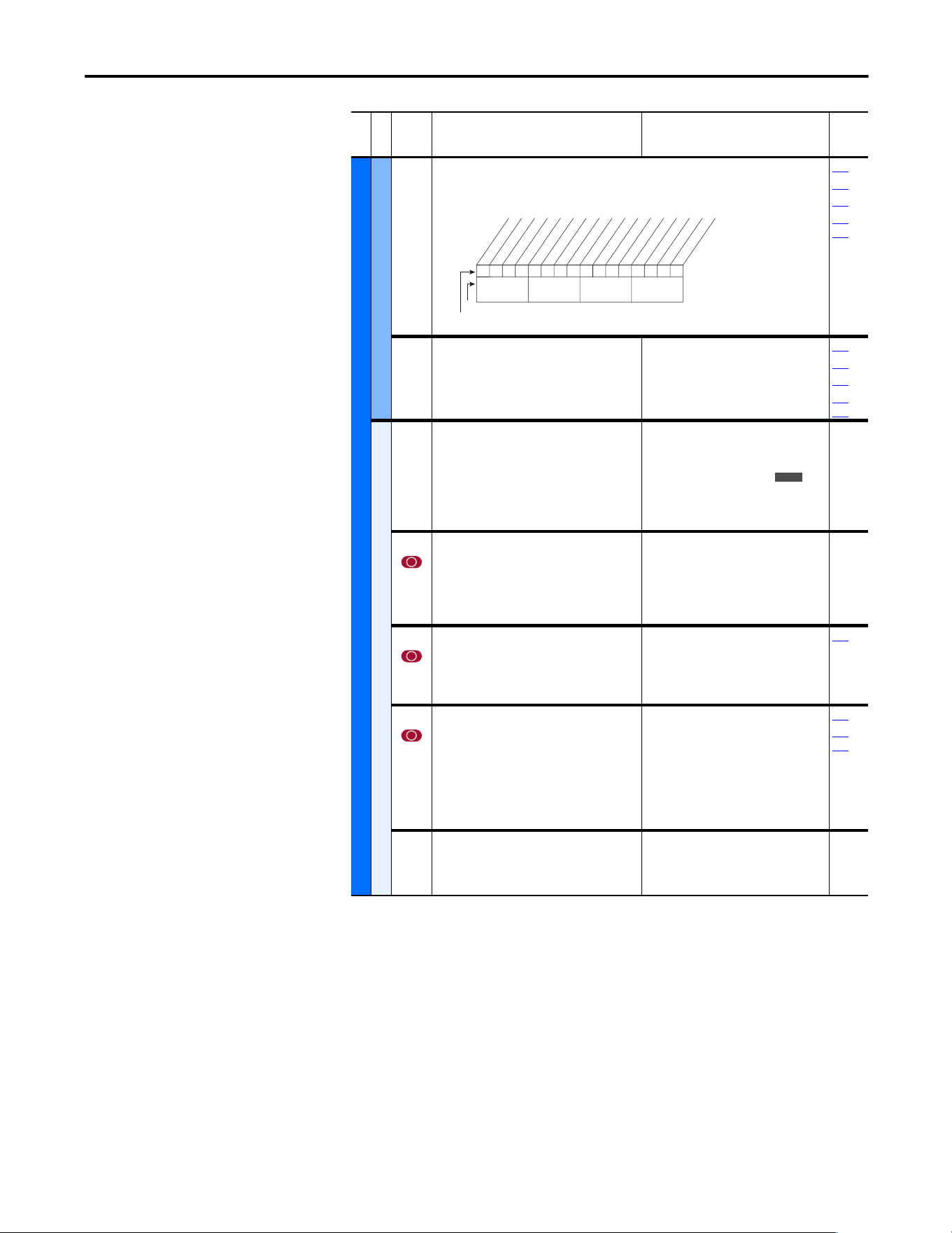
Rockwell Automation Publication 20A-UM001P-EN-P - February 2018 49
Programming and Parameters Chapter 1
UTILITY (file E)
MOP Config
194 [Save MOP Ref]
Enables/disables the feature that saves the present MOP frequency reference at power down
or at stop.
090
093
096
361…
366
195 [MOP Rate]
Sets rate of change of the MOP reference in
response to a digital input.
Default:
Min/Max:
Units:
1.0 Hz/s
0.2/[Maximum Freq]
0.1 Hz/s
090
093
096
361…
366
Drive Memory
196 [Param Access Lvl]
Selects the parameter display level viewable on
the HIM.
Basic = Reduced param. set
Advanced = Full param. set
Reserved = Full param. set and Engineering
params.
Default:
Options:
0
0
1
2
“Basic”
“Basic”
“Ad va nc ed ”
“Reserved”
197 [Reset To Defalts]
Resets all parameter values (except parameters
196, 201, and 202) to defaults. Option 1 resets
drive to factory settings. Options 2 and 3 reset
the drive to alternate voltage and current
rating.
Default:
Options:
0
0
1
2
3
“Ready”
“Ready”
“Factory”
“Low Voltage”
“High Voltage”
198 [Load Frm Usr Set]
Loads a previously saved set of parameter
values from a selected user set location in drive
nonvolatile memory to active drive memory.
Default:
Options:
0
0
1
2
3
“Ready”
“Ready”
“User Set 1”
“User Set 2”
“User Set 3”
199
199 [Save To User Set]
Saves the parameter values in active drive
memory to a user set in drive nonvolatile
memory.
To maintain control consistency when you are
using the drive inputs (P361…P366), verify
that the input settings are identical in each of
the user sets.
Default:
Options:
0
0
1
2
3
“Ready”
“Ready”
“User Set 1”
“User Set 2”
“User Set 3”
198
361…
366
200 [Reset Meters]
Resets selected meters to zero.
Default:
Options:
0
0
1
2
“Ready”
“Ready”
“MWh”
“Elapsed Time”
File E
Group
No.
Parameter Name and Description
(1)
Values
Related
0xx 0xxxxxxxxxxxx
10 01234567891112131415
1 = Save
0 = Do Not Save
x = Reserved
Bit #
Factory Default Bit Values
At Powr Down
At Stop
Nibble 1Nibble 2Nibble 3Nibble 4
E C
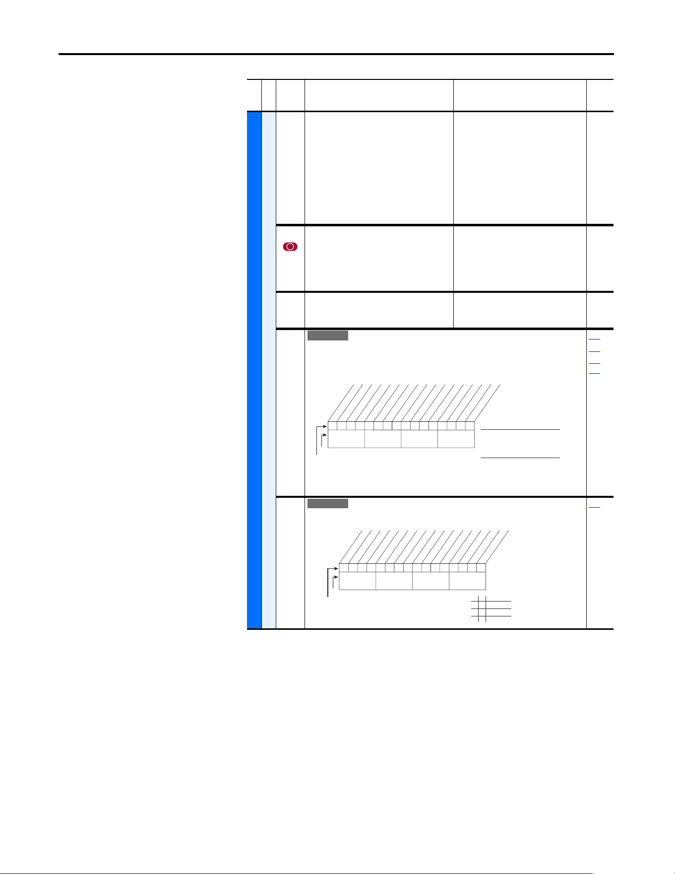
50 Rockwell Automation Publication 20A-UM001P-EN-P - February 2018
Chapter 1 Programming and Parameters
UTILITY (file E)
Drive Memory
201 [Language]
Selects the display language when you are
using an LCD HIM. This parameter is not
functional with an LED HIM.
Default:
Options:
0
0
1
2
3
4
5
6
7
8, 9
10
“Not Selected”
“Not Selected”
“English”
“Français”
“Español”
“Italiano”
“Deutsch”
“Reserved”
“Português”
“Reserved”
“Nederlands”
202 [Voltage Class]
Configures the drive current rating and
associates it with the selected voltage
(for example, 400V or 480V). This parameter is
normally used when downloading parameter
sets.
Default:
Options: 2
3
Based on Drive Cat. No.
“Low Voltage”
“High Voltage”
203 [Drive Checksum]
Provides a checksum value that indicates if a
change in drive programming has occurred.
Default:
Min/Max:
Units:
Read Only
0/65535
1
204 [Dyn UsrSet Cnfg]
Enables/Disables dynamic selection of user parameter sets.
Important: In dynamic mode, changes to the parameters are not saved to nonvolatile
storage. Switching user sets restores the values last saved before enabling dynamic mode.
198
199
361…
366
205 [Dyn UsrSet Sel]
Selects user set if [Dyn UsrSet Cnfg] = xxx xx11.
204
File E
Group
No.
Parameter Name and Description
(1)
Values
Related
E C v2
0xx 0xxxxxxxxxxxx
10 01234567891112131415
Dynamic Mode (Digital Inputs)
1 = Enabled
0 = Disabled
Ctrl Source (Comms)
1 = [Dyn UserSet Sel]
0 = Digital Inputs
x = Reserved
Bit #
Factory Default Bit Values
Dynamic Mode
Ctrl Source
Nibble 1Nibble 2Nibble 3Nibble 4
E C v2
0xx 0xxxxxxxxxxxx
10 01234567891112131415
1 = Enabled
0 = Disabled
x = Reserved
Bit #
Factory Default Bit Values
UserSet Sel1
UserSet Sel2
Nibble 1Nibble 2Nibble 3Nibble 4
0 0 User Set 1
0 1 User Set 2
1 0 User Set 3
1 1 User Set 3
Rockwell Automation Publication 20A-UM001P-EN-P - February 2018 51
Programming and Parameters Chapter 1
UTILITY (file E)
Drive Memory
206 [Dyn UserSet Actv]
Indicates the active user set and if the operation is dynamic or
normal.
Read Only
198
199
361…
366
Diagnostics
209 [Drive Status 1]
Present operating condition of the drive.
Read Only
210
213
210 [Drive Status 2]
Present operating condition of the drive.
Read Only
209
File E
Group
No.
Parameter Name and Description
(1)
Values
Related
E C v2
0000xxxxxxxxxxxx
10 01234567891112131415
1 =Condition True
0 =Condition False
x = Reserved
Bit #
Factory Default Bit Values
Dynamic Mode
User Set 1
User Set 3
User Set 2
Nibble 1Nibble 2Nibble 3Nibble 4
0110000001110000
10 01234567891112131415
1 = Condition True
0 = Condition False
x = Reserved
Bit #
Ready
Active
Command Dir
Actual Dir
Accelerating
Decelerating
Alarm
Faulted
At Speed
Local ID 0
(1)
Local ID 1
(1)
Local ID 2
(1)
Spd Ref ID 0
(2)
Spd Ref ID 1
(2)
Spd Ref ID 2
(2)
Spd Ref ID 3
(2)
Nibble 1Nibble 2Nibble 3Nibble 4
Bits
(2)
Description
Bits
(1)
Description15 14 13 12 11 10 9
0
0
0
0
0
0
0
0
1
1
1
1
1
1
1
1
0
0
0
0
1
1
1
1
0
0
0
0
1
1
1
1
0
0
1
1
0
0
1
1
0
0
1
1
0
0
1
1
0
1
0
1
0
1
0
1
0
1
0
1
0
1
0
1
Ref A Auto
Ref B Auto
Preset 2 Auto
Preset 3 Auto
Preset 4 Auto
Preset 5 Auto
Preset 6 Auto
Preset 7 Auto
TB Manual
Port 1 Manual
Port 2 Manual
Port 3 Manual
Port 4 Manual
Port 5 Manual
Port 6 Manual
Jog Ref
0
0
0
0
1
1
1
1
0
0
1
1
0
0
1
1
0
1
0
1
0
1
0
1
Port 0 (TB)
Port 1
Port 2
Port 3
Port 4
Port 5
Port 6
No Local
Control
00000000000000xx
10 01234567891112131415
1 =Condition True
0 =Condition False
x =Reserved
Bit #
Ready
Active
Running
Jogging
Stopping
DC Braking
AutoTuning
DB Active *
AutoRst Ctdn
AutoRst Act
Curr Limit
Bus Freq Reg
Motor Overld
DPI at 500 k
Nibble 1Nibble 2Nibble 3Nibble 4
* Enhanced Control Option Only.
52 Rockwell Automation Publication 20A-UM001P-EN-P - February 2018
Chapter 1 Programming and Parameters
UTILITY (file E)
Diagnostics
211 [Drive Alarm 1]
Alarm conditions that currently exist in the drive.
See Chapter 2 for information on Type 1 alarms.
Read Only
212
212 [Drive Alarm 2]
Alarm conditions that currently exist in the drive.
See Chapter 2 for information on Type 2 alarms.
Read Only
211
File E
Group
No.
Parameter Name and Description
(1)
Values
Related
000000x00000000x
10 01234567891112131415
1 =Condition True
0 =Condition False
x =Reserved
Bit #
Prechrg Actv
UnderVoltage
Power Loss
Str At PwrUp
Anlg in Loss
IntDBRes OH
Drv OL Lvl 1
Drv OL Lvl 2
Decel Inhibt
Waking
(2)
Motor Therm
(1)
In PhaseLoss
(2)
Load Loss
(2)
Ground Warn
(2)
Nibble 1Nibble 2Nibble 3Nibble 4
(1)
Enhanced firmware 1.001 & later.
(2)
Enhanced firmware 2.001 & later.
000000000000000x
10 01234567891112131415
1 = Condition True
0 = Condition False
x = Reserved
Bit #
DigIn CflctA
DigIn CflctB
DigIn CflctC
Bipolr Cflct
MtrTyp Cflct
NP Hz Cflct
MaxFrq Cflct
VHz NegSlope
IR Vlts Rang
FlxAmps Rang
SpdRef Cflct
Ixo Volt Rang
(2)
Sleep Config
(2)
TB Ref Cflct
(1)
PTC Conflict
(1)
Nibble 1Nibble 2Nibble 3Nibble 4
x0xxxxxxxxxxxxxx
26 161718192021222324252728293031
1 = Condition True
0 = Condition False
x = Reserved
Bit #
UserSetCflct
(2)
Nibble 1Nibble 2Nibble 3Nibble 4
(1)
Enhanced firmware 1.001 & later.
(2)
Enhanced firmware 2.001 & later.
Rockwell Automation Publication 20A-UM001P-EN-P - February 2018 53
Programming and Parameters Chapter 1
UTILITY (file E)
Diagnostics
213 [Speed Ref Source]
Displays the source of the speed reference to
the drive.
(1)
Displays after Start is pressed.
(2)
Only Enhanced Control Drives.
Default:
Options: 0
1
2
3…7
8
9
10
11
12
13
14
15
16
17
18
19
20
21
22
23, 24
25
26
27…2
9
30
Read Only
“PI Output”
(1)
“Analog In 1”
“Analog In 2”
“Reserved”
“Encoder”
“MOP Level”
“Reserved”
“Preset Spd1”
“Preset Spd2”
“Preset Spd3”
“Preset Spd4”
“Preset Spd5”
“Preset Spd6”
“Preset Spd7”
“DPI Port 1”
“DPI Port 2”
“DPI Port 3”
“Reserved”
“DPI Port 5”
“Reserved”
“Scale Block1”
“Scale Block2”
“Reserved”
“HighRes Ref”
(2)
002
090
093
096
101
214 [Start Inhibits]
Displays the inputs currently preventing the drive from
starting.
Read Only
243
361…
366
215 [Last Stop Source]
Displays the source that initiated the most
recent stop sequence. The display is cleared (set
to 0) during the next start sequence.
Default:
Options: 0
1
2
3
4
5
6
7
8
9
10
11
12
13
14
Read Only
“Pwr Removed”
“DPI Port 1”
“DPI Port 2”
“DPI Port 3”
“Reserved”
“DPI Port 5”
“Reserved”
“Digital In”
“Fault”
“Not Enabled”
“Sleep”
“Jo g”
“Autotune”
“Precharge”
“Safe Off”
361…
366
File E
Group
No.
Parameter Name and Description
(1)
Values
Related
000000000000x0xx
10 01234567891112131415
1 = Inhibit True
0 = Inhibit False
x = Reserved
Bit #
Fault
Type 2 Alarm
Enable
DC Bus Pchrg
Stop Assertd
Params Reset
StartUp Actv
Safe Off
(1)
Digital In
DPI Port 1
DPI Port 2
DPI Port 3
Reserved
DPI Port 5
Nibble 1Nibble 2Nibble 3Nibble 4
(1)
Enhanced firmware 3.002 & later.
E C
E C
E C v3
54 Rockwell Automation Publication 20A-UM001P-EN-P - February 2018
Chapter 1 Programming and Parameters
UTILITY (file E)
Diagnostics
216 [Dig In Status]
Status of the digital inputs.
Read Only
361…
366
411
217 [Dig Out Status]
Status of the digital outputs.
Read Only
380…
384
218 [Drive Temp]
Present operating temperature of the drive
power section.
For heatsink temperature, refer to P234
[Testpoint 1 Sel].
Default:
Min/Max:
Units:
Read Only
±100 degC
0.0/100.0%
1.0 degC
0.1%
219 [Drive OL Count]
Accumulated percentage of drive overload.
Continuously operating the drive over 100% of
its rating increases this value to 100% and
cause a drive fault or foldback depending on
the setting of [Drive OL Mode].
Default:
Min/Max:
Units:
Read Only
0.0/100.0%
0.1%
150
220 [Motor OL Count]
Accumulated percentage of motor overload.
Continuously operating the motor over 100% of
the motor overload setting increases this value
to 100% and cause a drive fault.
Default:
Min/Max:
Units:
Read Only
0.0/100.0%
0.1%
047
048
221 [Mtr OL Trip Time]
Amount of time before a drive Overload
fault(f64) occurs if the load condition remains
constant. A value of 99999 means that the drive
is operating under the overload level.
Default:
Min/Max:
Units:
Read Only
0/99999
1
220
File E
Group
No.
Parameter Name and Description
(1)
Values
Related
000000xx000000xx
10 01234567891112131415
1 =Input Present
0 =Input Not Present
x =Reserved
Bit #
Digital In1
Digital In2
Digital In3
Digital In4
Digital In5
Digital In6
In1 DLogRslt
(1)
In2 DLogRslt
(1)
In3 DLogRslt
(1)
In4 DLogRslt
(1)
In5 DLogRslt
(1)
In6 DLogRslt
(1)
Nibble 1Nibble 2Nibble 3Nibble 4
(1)
Enhanced firmware 2.001 & later.
0xx 0xxxxxxxxxxxx
10 01234567891112131415
1 =Output Energized
0 =Output De-energized
x =Reserved
Bit #
Digital Out1
Digital Out2
Nibble 1Nibble 2Nibble 3Nibble 4
E C
E C
E C v3
Rockwell Automation Publication 20A-UM001P-EN-P - February 2018 55
Programming and Parameters Chapter 1
UTILITY (file E)
Diagnostics
222 [Drive Status 3]
Present operating condition of the drive.
Manual Mode - See “Manual” Speed Sources
on page 111.
Fast Braking - Fast Braking is active, see [Stop/Brk Mode A]
[Stop/Brk Mode B] on page 41.
Read Only
223 [Status 3 @ Fault]
Captures and displays [Drive Status 3] bit pattern at the
time of the last fault.
Read Only
224 [Fault Frequency]
Captures and displays the output speed of the
drive at the time of the last fault.
Default:
Min/Max:
Units:
Read Only
0.0/+[Maximum Freq]
0.1 Hz
225…
230
225 [Fault Amps]
Captures and displays motor amps at the time
of the last fault.
Default:
Min/Max:
Units:
Read Only
0.0/[Rated Amps] 2
0.1 Amps
224…
230
226 [Fault Bus Volts]
Captures and displays the DC bus voltage of the
drive at the time of the last fault.
Default:
Min/Max:
Units:
Read Only
0.0/Max Bus Volts
0.1V DC
224…
230
227 [Status 1 @ Fault]
Captures and displays [Drive Status 1] bit pattern at the
time of the last fault.
Read Only
209
224…
230
File E
Group
No.
Parameter Name and Description
(1)
Values
Related
E C v3
0xx 0xxxxxxxxxxxx
10 01234567891112131415
1 = Condition True
0 = Condition False
x = Reserved
Bit #
Factory Default Bit Values
Manual Mode
Fast Braking
Nibble 1Nibble 2Nibble 3Nibble 4
E C v3
0xx 0xxxxxxxxxxxx
10 01234567891112131415
1 = Condition True
0 = Condition False
x = Reserved
Bit #
Factory Default Bit Values
Manual Mode
Fast Braking
Nibble 1Nibble 2Nibble 3Nibble 4
0110000101110000
10 01234567891112131415
1 = Condition True
0 = Condition False
x = Reserved
Bit #
Ready
Active
Command Dir
Actual Dir
Accelerating
Decelerating
Alarm
Faulted
At Speed
Local ID 0
Local ID 1
Local ID 2
Spd Ref ID 0
Spd Ref ID 1
Spd Ref ID 2
Spd Ref ID 3
Nibble 1Nibble 2Nibble 3Nibble 4
56 Rockwell Automation Publication 20A-UM001P-EN-P - February 2018
Chapter 1 Programming and Parameters
UTILITY (file E)
Diagnostics
228 [Status 2 @ Fault]
Captures and displays [Drive Status 2] bit pattern at the
time of the last fault.
Read Only
210
224…
230
229 [Alarm 1 @ Fault]
Captures and displays [Drive Alarm 1] at the time of the last
fault.
Read Only
211
224…
230
230 [Alarm 2 @ Fault]
Captures and displays [Drive Alarm 2] at the time of the last
fault.
Read Only
212
224…
230
File E
Group
No.
Parameter Name and Description
(1)
Values
Related
00000000000000xx
10 01234567891112131415
1 = Condition True
0 = Condition False
x = Reserved
Bit #
Ready
Active
Running
Jogging
Stopping
DC Braking
AutoTuning
DB Active *
AutoRst Ctdn
AutoRst Act
Curr Limit
Bus Freq Reg
Motor Overld
DPI at 500 k
Nibble 1Nibble 2Nibble 3Nibble 4
* Enhanced Control Option Only.
000000x00000000x
10 01234567891112131415
1 =Condition True
0 =Condition False
x =Reserved
Bit #
Prechrg Actv
UnderVoltage
Power Loss
Str At PwrUp
Anlg in Loss
IntDBRes OH
Drv OL Lvl 1
Drv OL LVl 2
Decel Inhibt
Waking
(2)
Motor Therm
(1)
In PhaseLoss
(2)
Load Loss
(2)
Ground Warn
(2)
Nibble 1Nibble 2Nibble 3Nibble 4
(1)
Enhanced firmware 1.001 & later.
(2)
Enhanced firmware 2.001 & later.
000000000000000x
10 01234567891112131415
1 = Condition True
0 = Condition False
x = Reserved
Bit #
DigIn CflctA
DigIn CflctB
DigIn CflctC
Bipolr Cflct
MtrTyp Cflct
NP Hz Cflct
MaxFrq Cflct
VHz NegSlope
IR Vlts Rang
FlxAmps Rang
SpdRef Cflct
Ixo Volt Rang
(2)
Sleep Config
(2)
TB Ref Cflct
(1)
PTC Conflict
(1)
Nibble 1Nibble 2Nibble 3Nibble 4
x0xxxxxxxxxxxxxx
26 161718192021222324252728293031
1 = Condition True
0 = Condition False
x = Reserved
Bit #
UserSetCflct
(2)
Nibble 1Nibble 2Nibble 3Nibble 4
(1)
Enhanced firmware 1.001 & later.
(2)
Enhanced firmware 2.001 & later.
Rockwell Automation Publication 20A-UM001P-EN-P - February 2018 57
Programming and Parameters Chapter 1
UTILITY (file E)
Diagnostics
234
236
[Testpoint 1 Sel]
[Testpoint 2 Sel]
Selects the function whose value is displayed
value in [Testpoint x Data].
These are internal values that are not accessible
through parameters.
See Testpoint Codes and Functions
on page 85
for a listing of available codes and functions.
Default:
Min/Max:
Units:
499
0/999
0/65535
1
235
237
235
237
[Testpoint 1 Data]
[Testpoint 2 Data]
The present value of the function that is
selected in [Testpoint x Sel].
Default:
Min/Max:
Units:
Read Only
0/65535
±2147483647
1
234
236
Faults
238 [Fault Config 1]
Enables/disables annunciation of the listed faults.[
189
240 [Fault Clear]
Resets a fault and clears the fault queue.
Default:
Options:
0
0
1
2
“Ready”
“Ready”
“Clear Faults”
“Clr Flt Que”
241 [Fault Clear Mode]
Enables/disables a fault reset (clear faults)
attempt from any source. This does not apply to
fault codes that are cleared indirectly via other
actions.
Default:
Options:
1
0
1
“Enabled”
“Disabled”
“Enabled”
242 [Power Up Marker]
Elapsed hours from the initial drive powerup.
This value rolls over to 0 after the drive has been
powered on for more than the max value
shown. The parameter value only updates at
powerup. For relevance to most recent powerup
see [Fault x Time] on page 58
.
Default:
Min/Max:
Units:
Read Only
0.0000/429496.7295 Hrs
0.0001 Hrs
246
File E
Group
No.
Parameter Name and Description
(1)
Values
Related
E C
32
E C
E C
1x1 0001000x0xxxx
10 01234567891112131415
1 = Enabled
0 = Disable
x = Reserved
Bit #
Factory Default Bit Values
Power Loss
UnderVoltage
HS Low Temp
(3)
Motor OverLd
Shear Pin
AutRst Tries
Decel Inhibt
Motor Therm
(1)
In PhaseLoss
(2)
Load Loss
(2)
ShearPNo Acc
(1)(4
Nibble 1Nibble 2Nibble 3Nibble 4
(1)
Enhanced firmware 1.001 & later.
(2)
Enhanced firmware 2.001 & later.
(3)
Enhanced firmware 4.001 & later.
(4)
Bit 11 enables the shear pin fault to be ignored
during acceleration and deceleration. Using Bit 11 with
Bit 4 set to ‘0’ will have no effect.
32
58 Rockwell Automation Publication 20A-UM001P-EN-P - February 2018
Chapter 1 Programming and Parameters
UTILITY (file E)
Faults
243
245
247
249
[Fault 1 Code]
[Fault 2 Code]
[Fault 3 Code]
[Fault 4 Code]
A code that represents the fault that tripped the
drive. The codes appear in these parameters in
the order they occur ([Fault 1 Code] = the most
recent fault).
Default:
Min/Max:
Units:
Read Only
0/9999
0/65535
0
214
238
244
246
248
250
[Fault 1 Time]
[Fault 2 Time]
[Fault 3 Time]
[Fault 4 Time]
Default:
Min/Max:
Units:
Read Only
0.0000/429496.7295 Hrs
0.0001 Hrs
242
The time between initial drive powerup and the occurrence of the associated trip fault. Can
be compared to [Power Up Marker] for the time from the most recent powerup.
[Fault x Time] – [Power Up Marker] = Time difference to the most recent powerup. A
negative value indicates that a fault occurred before most recent powerup. A positive value
indicates that a fault occurred after most recent powerup.
To convert this value to the number of days, hours, minutes, and seconds, use the following
formulas:
• Fault x Time / 24 hours = (# of days).(remaining time)
• Remaining Time x 24 hours = (# of hours).(remaining time)
• Remaining Time x 60 minutes = (# of minutes).(remaining seconds)
• Remaining Time x 60 seconds = (# of seconds)
• Result = (# of days).(# of hours).(# of minutes).(# of seconds)
Example:
• 1909.2390 Hrs / 1 Day/24 Hrs = 79.551625 Days
• 0.551625 Days x 24 Hrs/Day = 13.239 Hrs
• 0.239 Hrs x 60 Min/Hr = 14.34 Min
• 0.34 Min x 60 Sec/Min = 20.4 Secs
Alarms
259 [Alarm Config 1]
Enables/disables alarm conditions that initiate an active drive alarm.
Scaled Blocks
476
482
[Scale1 In Value]
[Scale2 In Value]
Displays the value of the signal being sent to
[ScaleX In Value] by using a datalink.
Default:
Min/Max:
Units:
0.0
-3276.8/+3276.7
0.1
090
093
117
126
127
427
477
483
[Scale1 In Hi]
[Scale2 In Hi]
Scales the upper value of [ScaleX In Value].
Default:
Min/Max:
Units:
0.0
-3276.8/+3276.7
0.1
091
094
119
428
460
462
478
484
[Scale1 In Lo]
[Scale2 In Lo]
Scales the lower value of [ScaleX In Value].
Default:
Min/Max:
Units:
0.0
-3276.8/+3276.7
0.1
092
095
120
429
461
463
File E
Group
No.
Parameter Name and Description
(1)
Values
Related
E C
32
111111x11101000x
10 01234567891112131415
1 =Enabled
0 =Disabled
x =Reserved
Bit #
Factory Default Bit Values
Prechrg Actv
UnderVoltage
Power Loss
Str At PwrUp
Anlg in Loss
IntDBRes OH
Drv OL Lvl 1
Drv OL Lvl 2
Decel Inhibt
Waking
(2)
Motor Therm
(1)
In PhaseLoss
(2)
Load Loss
(2)
Ground Warn
(2)
Nibble 1Nibble 2Nibble 3Nibble 4
(1)
Enhanced firmware 1.001 & later.
(2)
Enhanced firmware 2.001 & later.
E C v4
E C v4
E C v4
E C v4
E C v4
E C v4
Rockwell Automation Publication 20A-UM001P-EN-P - February 2018 59
Programming and Parameters Chapter 1
Communication File (File H)
Diag-Motor Cntl
549 [Flux Braking %]
Gain adjustment for Flux Braking mode.
(Percentage of normal output voltage.)
This parameter is only viewable when
P196 [Param Access Lvl] = 2
“Reserved.”
Default: 125
Min/Max:100/250
Units:%
166
(1) See page 13 for Symbol Descriptions.
File E
Group
No.
Parameter Name and Description
(1)
Values
Related
File H
Group
No.
Parameter Name and Description
(1)
Values
Related
COMMUNICATION (file H)
Comm Control
270 [DPI Data Rate]
Sets the baud rate for attached drive peripherals.
When changing this value the drive must be reset for
the change to take effect.
Default:
Options:
0
0
1
“125 kbps”
“125 kbps”
“500 kbps”
271 [Drive Logic Rslt]
The final logic command resulting from the combination of all
DPI and discrete inputs. This parameter has the same structure as
the product-specific logic command received via DPI and is used
in peer to peer communications.
Read Only
272 [Drive Ref Rslt]
Present frequency reference that is scaled as a DPI
reference for peer to peer communications. The value
that is shown is the value prior to the accel/decel
ramp and any corrections that are supplied by slip
comp, PI, and so on.
Default:
Min/Max:
Units:
Read Only
±32767
1
273 [Drive Ramp Rslt]
Present frequency reference that is scaled as a DPI
reference for peer to peer communications. The value
that is shown is the value after the accel/decel ramp
but prior to any corrections supplied by slip comp, PI,
and so on.
Default:
Min/Max:
Units:
Read Only
±32767
1
0110000101111110
10 01234567891112131415
1 =Condition True
0 =Condition False
x =Reserved
Bit #
Stop
Start
Jog
Clear Fault
Forward
Reverse
Local Contrl
MOP Inc
Accel 1
Accel 2
Decel 1
Decel 2
Spd Ref ID 0
(1)
Spd Ref ID 1
(1)
Spd Ref ID 2
(1)
MOP Dec
Nibble 1Nibble 2Nibble 3Nibble 4
Bits
(1)
Description14 13 12
0
0
0
0
1
1
1
1
0
0
1
1
0
0
1
1
0
1
0
1
0
1
0
1
No Command - Man. Mode
Ref A Auto
Ref B Auto
Preset 3 Auto
Preset 4 Auto
Preset 5 Auto
Preset 6 Auto
Preset 7 Auto
60 Rockwell Automation Publication 20A-UM001P-EN-P - February 2018
Chapter 1 Programming and Parameters
COMMUNICATION (file H)
Comm Control
274 [DPI Port Select]
Selects the port reference value that appears in [DPI
Port Value].
Default:
Options:
0
0
1
2
3
4
5
“Not Used”
“Not Used”
“DPI Port 1”
“DPI Port 2”
“DPI Port 3”
“Reserved”
“DPI Port 5”
275 [DPI Port Value]
Value of the DPI reference that is selected in [DPI Port
Sel].
Default:
Min/Max:
Units:
Read Only
±32767
1
298 [DPI Ref Select]
Scales DPI on [Maximum Freq] or [Maximum Speed].
This adjusts the resolution of the DPI reference.
Default:
Options:
0
0
1
“Max Freq”
“Max Freq”
“Max Speed”
055
082
Masks and Owners
276 [Logic Mask]
Determines the adapters that can control the drive when 598, bit 15 is set to “1.” If the bit for an
adapter is “0,” the adapter has no control functions except for stop.
288
…
297
277 [Start Mask]
Controls the adapters that can issue start commands.
See P276 [Logic Mask].
288…
297
278 [Jog Mask]
Controls the adapters that can issue jog commands.
See P276 [Logic Mask].
288…
297
279 [Direction Mask]
Controls the adapters that can issue forward/reverse
direction commands.
See P276 [Logic Mask].
288…
297
280 [Reference Mask]
Controls the adapters that can select an alternate
reference; [Speed Ref A, B Sel] or [Preset Speed
1…7].
See P276 [Logic Mask].
288…
297
281 [Accel Mask]
Controls the adapters that can select [Accel Time 1,
2].
See P276 [Logic Mask].
288…
297
282 [Decel Mask]
Controls the adapters that can select [Decel Time 1,
2].
See P276 [Logic Mask].
288…
297
283 [Fault Clr Mask]
Controls the adapters that can clear a fault.
See P276 [Logic Mask].
288…
297
File H
Group
No.
Parameter Name and Description
(1)
Values
Related
E C
E C
E C
1111x1xxxxxxxxxx
10 01234567891112131415
1 = Control Permitted
0 = Control Masked
x = Reserved
Bit #
Factory Default Bit Values
Digital In
DPI Port 1
DPI Port 2
DPI Port 3
DPI Port 5
Nibble 1Nibble 2Nibble 3Nibble 4
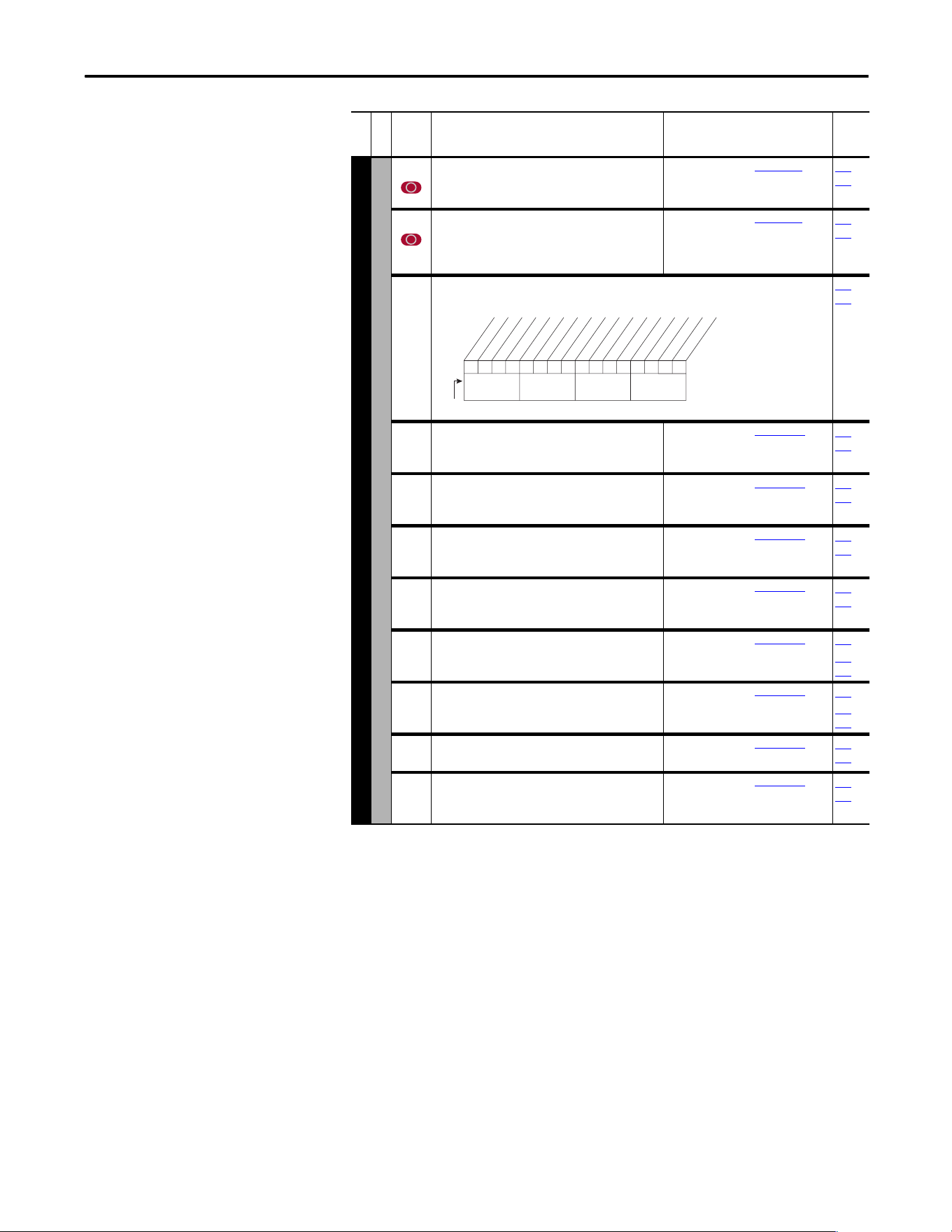
Rockwell Automation Publication 20A-UM001P-EN-P - February 2018 61
Programming and Parameters Chapter 1
COMMUNICATION (file H)
Masks and Owners
284 [MOP Mask]
Controls the adapters that can issue MOP commands
to the drive.
See P276 [Logic Mask].
288…
297
285 [Local Mask]
Controls the adapters that take exclusive control of
drive logic commands (except stop). Exclusive “local”
control can only be taken while the drive is stopped.
See P276 [Logic Mask].
288…
297
288 [Stop Owner]
Adapters that are presently issuing a valid stop command.
Read Only
276…
285
289 [Start Owner]
Adapters that are presently issuing a valid start
command.
See P288 [Stop Owner].
276…
285
290 [Jog Owner]
Adapters that are presently issuing a valid jog
command.
See P288 [Stop Owner].
276…
285
291 [Direction Owner]
Adapter that currently has exclusive control of
direction changes.
See P288 [Stop Owner].
276…
285
292 [Reference Owner]
Adapter that has the exclusive control of the
command frequency source selection.
See P288 [Stop Owner].
276…
285
293 [Accel Owner]
Adapter that has exclusive control of selecting [Accel
Time 1, 2].
See P288 [Stop Owner].
140
276…
285
294 [Decel Owner]
Adapter that has exclusive control of selecting [Decel
Time 1, 2].
See P288 [Stop Owner].
142
276…
285
295 [Fault Clr Owner]
Adapter that is presently clearing a fault.
See P288 [Stop Owner].
276…
285
296 [MOP Owner]
Adapters that are currently issuing increases or
decreases in MOP command frequency.
See P288 [Stop Owner].
276…
285
File H
Group
No.
Parameter Name and Description
(1)
Values
Related
0001x0xxxxxxxxxx
10 01234567891112131415
1 = Issuing Command
0 = No Command
x = Reserved
Bit #
Digital In
DPI Port 1
DPI Port 2
DPI Port 3
DPI Port 5
Nibble 1Nibble 2Nibble 3Nibble 4
62 Rockwell Automation Publication 20A-UM001P-EN-P - February 2018
Chapter 1 Programming and Parameters
COMMUNICATION (file H)
Masks and Owners
297 [Local Owner]
Adapter that has requested exclusive control of all
drive logic functions. If an adapter is in local lockout,
all other functions (except stop) on all other adapters
are locked out and non-functional. Local control can
only be obtained when the drive is not running.
See P288 [Stop Owner].
276…
285
Datalinks
300
301
[Data In A1] - Link A Word 1
[Data In A2] - Link A Word 2
Parameter number whose value is written from a
communications device data table.
Parameters that can be changed only while drive is
stopped cannot be used as Datalink inputs. Entering
a parameter of this type disables the link.
Refer to your communications option manual for
datalink information.
Default:
Min/Max:
Units:
0 (0 = “Disabled”)
0/387
0/545
0/598
1
302
303
[Data In B1] - Link B Word 1
[Data In B2] - Link B Word 2
See [Data In A1] - Link A Word 1.
304
305
[Data In C1] - Link C Word 1
[Data In C2] - Link C Word 2
See [Data In A1] - Link A Word 1.
306
307
[Data In D1] - Link D Word 1
[Data In D2] - Link D Word 2
See [Data In A1] - Link A Word 1.
310
311
[Data Out A1] - Link A Word 1
[Data Out A2] - Link A Word 2
Parameter number whose value is written to a
communications device data table.
Default:
Min/Max:
Units:
0 (0 = “Disabled”)
0/387
0/545
0/598
1
312
313
[Data Out B1] - Link B Word 1
[Data Out B2] - Link B Word 2
See [Data Out A1] - Link A Word 1.
314
315
[Data Out C1] - Link C Word 1
[Data Out C2] - Link C Word 2
See [Data Out A1] - Link A Word 1.
316
317
[Data Out D1] - Link D Word 1
[Data Out D2] - Link D Word 2
See [Data Out A1] - Link A Word 1.
308 [HighRes Ref]
Used as a high resolution, 32 bit reference with
Datalinks.
±[Maximum Freq] or
±[Maximum Speed] = 2147418112
Default:
Min/Max:
Units:
0
±2147483647
1
090
093
126
128
213
298
File H
Group
No.
Parameter Name and Description
(1)
Values
Related
E C
E C v2
E C
E C v2
32
E C
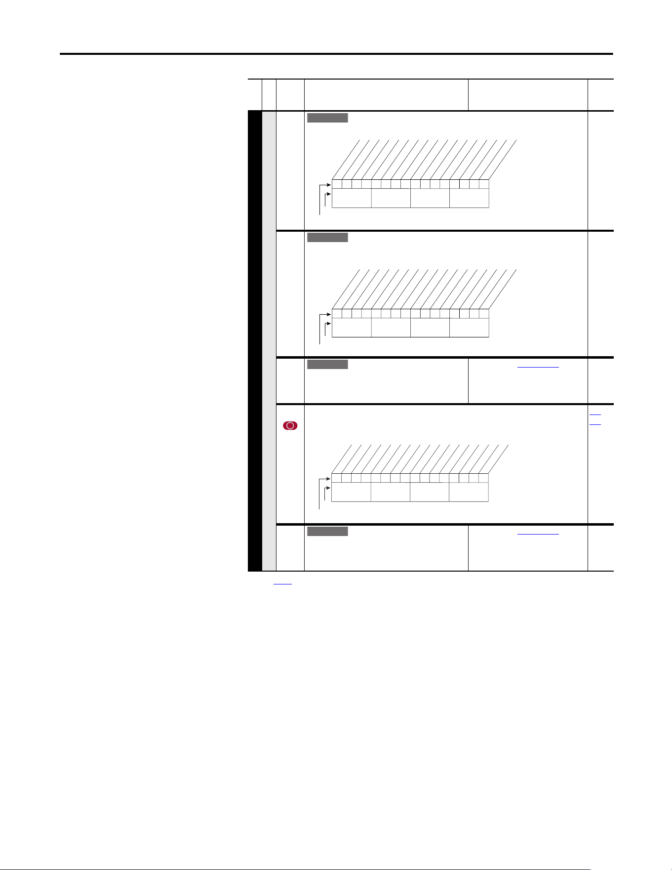
Rockwell Automation Publication 20A-UM001P-EN-P - February 2018 63
Programming and Parameters Chapter 1
COMMUNICATION (file H)
Security
595 [Port Mask Act]
Active status for port communication.
596 [Write Mask Cfg]
Enables/disables write access (parameters, and so on) for ports. Changes to this parameter
are affective after a power cycle, drive reset or when 597, bit 15 transitions from “1” to “0.”
597 [Write Mask Act]
Active status of write access for ports. Bit 15
determines if network security is controlling the
write mask instead of 596.
See [Port Mask Act].
276 [Logic Mask]
Determines the adapters that can control the drive when 597, bit 15 is set to “1”. If the bit for
a port is set to “0,” the port has no control functions except for stop.
288
…
297
598 [Logic Mask Act]
Active status of logic mask for ports. Bit 15
determines if network security is controlling the logic
mask instead of 276.
See [Port Mask Act].
(1) See
page 13 for Symbol Descriptions.
File H
Group
No.
Parameter Name and Description
(1)
Values
Related
E C v2
1 =Not Masked
0 =Masked
x =Reserved
1111x1xxxxxxxxx1
10 01234567891112131415
Bit #
Factory Default Bit Values
Host
DPI Port 1
DPI Port 2
DPI Port 3
DPI Port 5
Security
Nibble 1Nibble 2Nibble 3Nibble 4
E C v2
1 =Not Masked
0 =Masked
x =Reserved
1111x1xxxxxxxxxx
10 01234567891112131415
Bit #
Factory Default Bit Values
Host
DPI Port 1
DPI Port 2
DPI Port 3
DPI Port 5
Nibble 1Nibble 2Nibble 3Nibble 4
E C v2
1111x1xxxxxxxxxx
10 01234567891112131415
1 = Control Permitted
0 = Control Masked
x = Reserved
Bit #
Factory Default Bit Values
Digital In
DPI Port 1
DPI Port 2
DPI Port 3
DPI Port 5
Nibble 1Nibble 2Nibble 3Nibble 4
E C v2
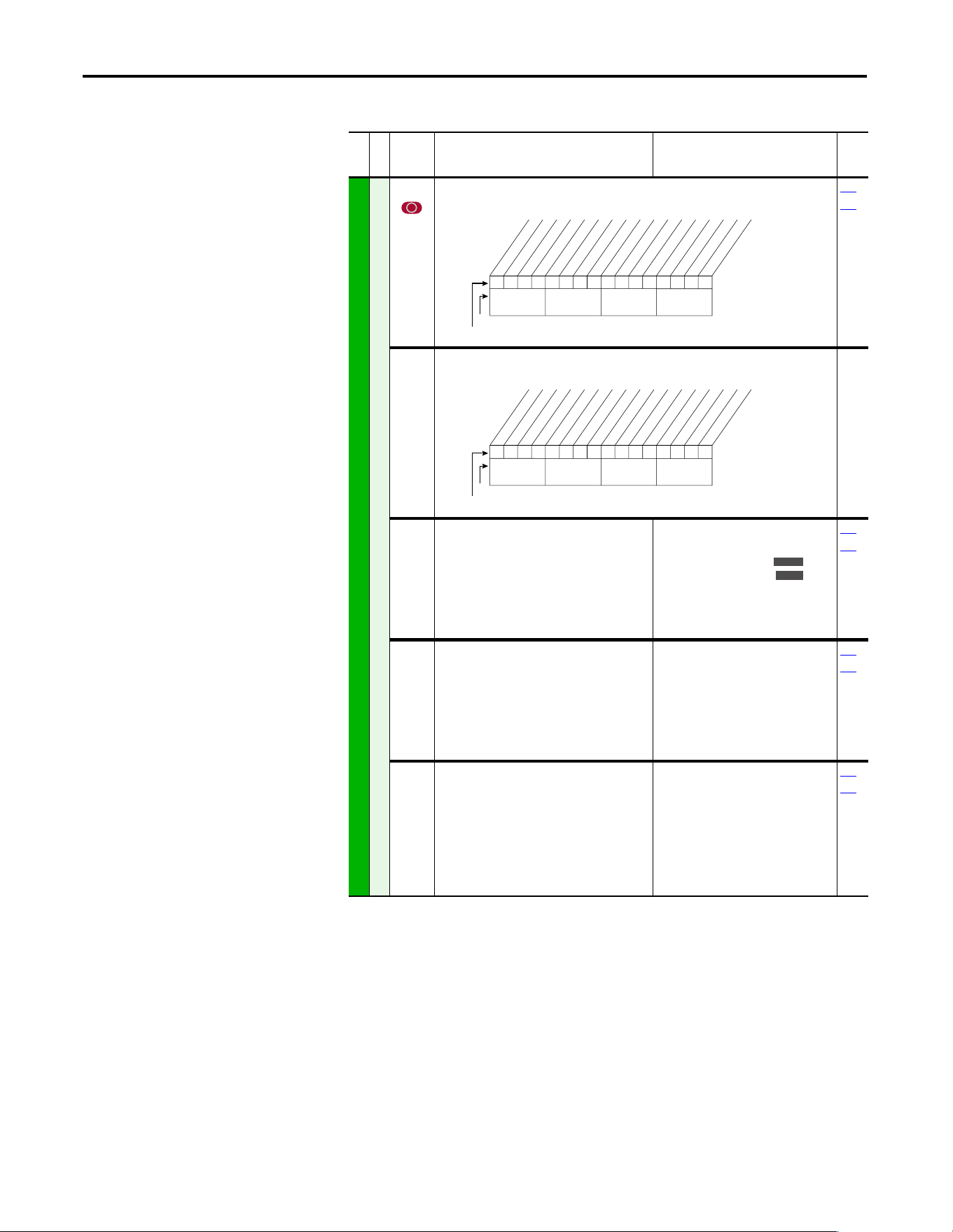
64 Rockwell Automation Publication 20A-UM001P-EN-P - February 2018
Chapter 1 Programming and Parameters
Inputs and Outputs File
(File J)
File J
Group
No.
Parameter Name and Description
(1)
Values
Related
INPUTS and OUTPUTS (file J)
Analog Inputs
320 [Anlg In Config]
Selects the mode for the analog inputs.
322
323
321 [Anlg In Sqr Root]
Enables/disables the square root function for each input.
322
325
[Analog In 1 Hi]
[Analog In 2 Hi]
Sets the highest input value to the analog input x
scaling block.
Default:
Min/Max:
Units:
10.000 Volt
10.000 Volt
4.000/20.000 mA ,
0.000/20.000 mA ,
±10.000V,
0.000/10.000V
0.001 mA,
0.001 Volts
091
092
323
326
[Analog In 1 Lo]
[Analog In 2 Lo]
Sets the lowest input value to the analog input x
scaling block.
Default:
Min/Max:
Units:
0.000 Volts
0.000 Volts
4.000/20.000 mA,
0.000/10.000V (No. 323),
±10.000V (No. 326)
0.000/10.000V,
0.001 mA,
0.001 Volts
091
092
324
327
[Analog In 1 Loss]
[Analog In 2 Loss]
Selects drive action when an analog signal loss is
detected. Signal loss is defined as an analog
signal less than 1V or 2 mA. The signal loss event
ends and normal operations resume when the
input signal level is greater than or equal to 1.5V
or 3 mA.
Default:
Options:
0
0
0
1
2
3
4
5
6
“Disabled”
“Disabled”
“Disabled”
“Fault”
“Hold Input”
“Set Input Lo”
“Set Input Hi”
“Goto Preset1”
“Hold OutFreq”
091
092
0xx 0xxxxxxxxxxxx
10 01234567891112131415
1 =Current
0 =Voltage
x =Reserved
Bit #
Factory Default Bit Values
Analog In 1
Analog In 2
Nibble 1Nibble 2Nibble 3Nibble 4
0xx 0xxxxxxxxxxxx
10 01234567891112131415
1 =Enable
0 =Disable
x =Reserved
Bit #
Factory Default Bit Values
Analog In 1
Analog In 2
Nibble 1Nibble 2Nibble 3Nibble 4
Standard
E C
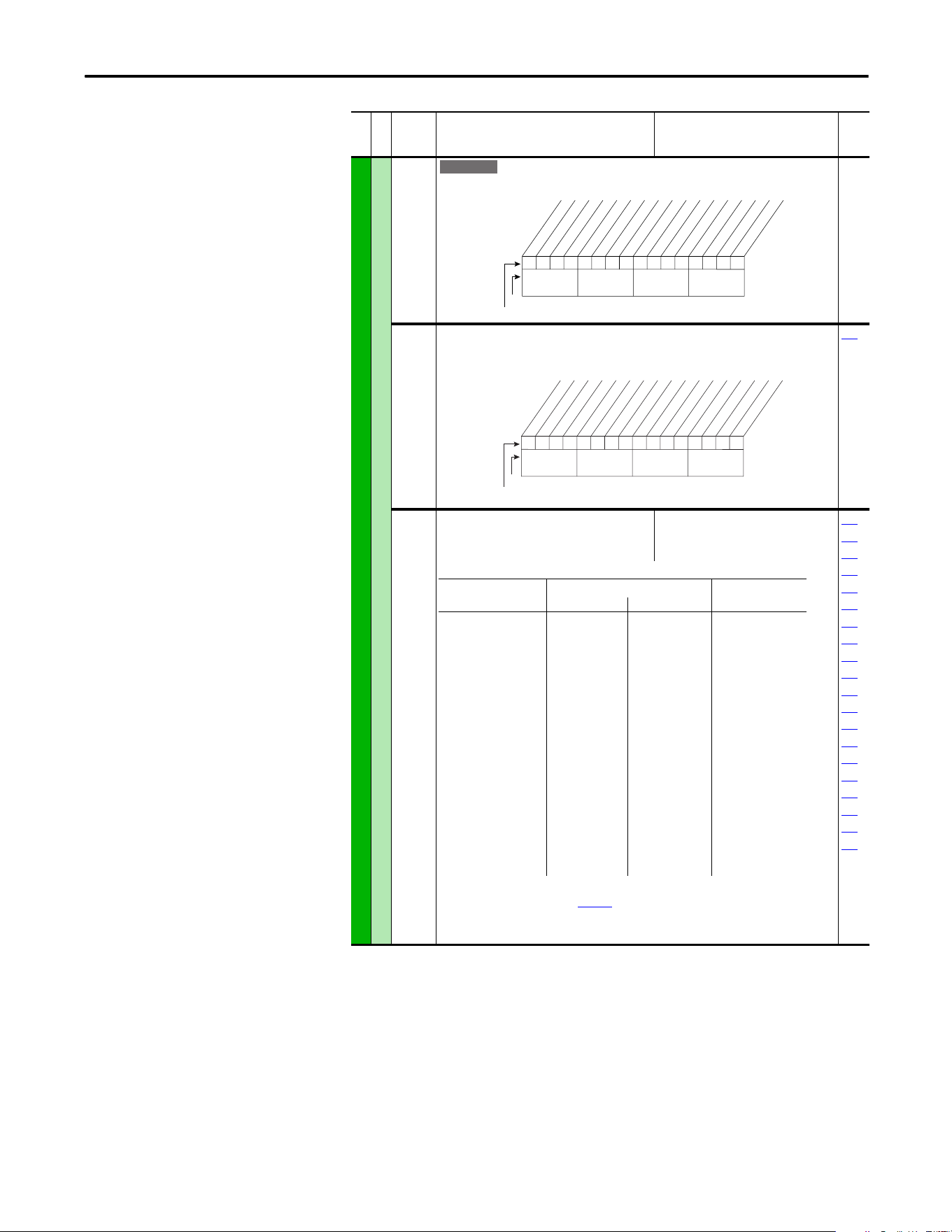
Rockwell Automation Publication 20A-UM001P-EN-P - February 2018 65
Programming and Parameters Chapter 1
INPUTS and OUTPUTS (file J)
Analog Outputs
340 [Anlg Out Config]
Selects the mode for the analog outputs.
341 [Anlg Out Absolut]
Selects whether the signed value or absolute value of a parameter is used before being scaled
to drive the analog output.
342
342 [Analog Out1 Sel]
Selects the source of the value that drives the
analog output.
Default:
Options:
0“Output Freq”
See Table
001
002
003
004
005
007
006
012
135
136
137
138
220
219
024
441
023
025
015
377
(1)
Refer to Option Definitions on page 70.
(2)
Enhanced firmware revision 1.001 and later.
(3)
Enhanced firmware revision 2.002 and later.
File J
Group
No.
Parameter Name and Description
(1)
Values
Related
E C
xxx 0xxxxxxxxxxxx
10 01234567891112131415
1 =Current
0 =Voltage
x =Reserved
Bit #
Factory Default Bit Values
Analog Out1
Nibble 1Nibble 2Nibble 3Nibble 4
xxx 1xxxxxxxxxxxx
10 01234567891112131415
1 = Absolute
0 = Signed
x = Reserved
Bit #
Factory Default Bit Values
Analog Out1
Nibble 1Nibble 2Nibble 3Nibble 4
Options [Analog Out1 Lo] Value [Analog Out1 Hi]
Value
Param. 341= Signed Param. 341 = Absolute
0
1
2
3
4
5
6
7
8
9
10
11
12
13
14
15
16
17
19
24
25
“Output Freq”
“Command Freq”
“Output Amps”
“Torque Amps”
“Flux Amps”
“Output Power”
“Output Volts”
“DC Bus Volts”
“PI Reference”
(1)
“PI Feedback”
“PI Error”
“PI Output”
“%Motor OL”
“%Drive OL”
“CommandedTrq:”
(3)
“MtrTrqCurRef”
(1)(3)
“Speed Ref”
(3)
“Speed Fdbk”
(3)
“Torque Est”
(1)(3)
“Param Cntl”
(1)(2)
“SpdFdBk NoFilt”
(1)
–[Maximum Speed]
–[Maximum Speed]
0 Amps
–200%
0 Amps
0 kW
0 Volts
0 Volts
–100%
–100%
–100%
–800%
0%
0%
–800%
–200%
–[Maximum Speed]
–[Maximum Speed]
–800%
–[Maximum Speed]
0 Hz
0 Hz
0 Amps
0 Amps
0 Amps
0 kW
0 Volts
0 Volts
0%
0%
0%
0%
0%
0%
0%
0 Amps
0 Hz
0 Hz
0%
0 Hz
+[Maximum Speed]
+[Maximum Speed]
200% Drive Rated
200% Drive Rated
200% Drive Rated
200% Drive Rated
120% Drive Rated
200% Drive Rated
100%
100%
100%
800%
100%
100%
800% Motor Rated
200% Motor Rated
[Maximum Speed]
[Maximum Speed]
800% Motor Rated
[Maximum Speed]
66 Rockwell Automation Publication 20A-UM001P-EN-P - February 2018
Chapter 1 Programming and Parameters
INPUTS and OUTPUTS (file J)
Analog Outputs
343 [Analog Out1 Hi]
Sets the analog output value when the source
value is at maximum.
Default:
Min/Max:
Units:
10.00 Volts
0.00/10.00 Volts
0.00/20.00 mA
0.01 Volts
0.01 mA
340
342
344 [Analog Out1 Lo]
Sets the analog output value when the source
value is at minimum.
Default:
Min/Max:
Units:
0.00 Volts
0.00/10.00 Volts
0.00/20.00 mA
0.01 Volts
0.01 mA
340
342
354 [Anlg Out1 Scale]
Sets the high value for the range of analog out
scale. Entering 0.0 disables this scale and max
scale is used. Example: If [Analog Out Sel] =
“Commanded Trq,” a value of 150 = 150% scale in
place of the default 800%.
Default:
Min/Max:
Units:
0.0
[Analog Out1 Sel]
0.01
341
342
377 [Anlg Out1 Setpt]
Controls the analog output value from a
communication device.
Example
Set [Data In A1] to “377” as the value from the
communication device.
Default:
Min/Max:
Units:
0.00 Volts
0.00/10.00 Volts
0.00/20.00 mA
0.01 Volts
0.01 mA
340
File J
Group
No.
Parameter Name and Description
(1)
Values
Related
E C
E C
E C
E C
E C
E C
E C
E C
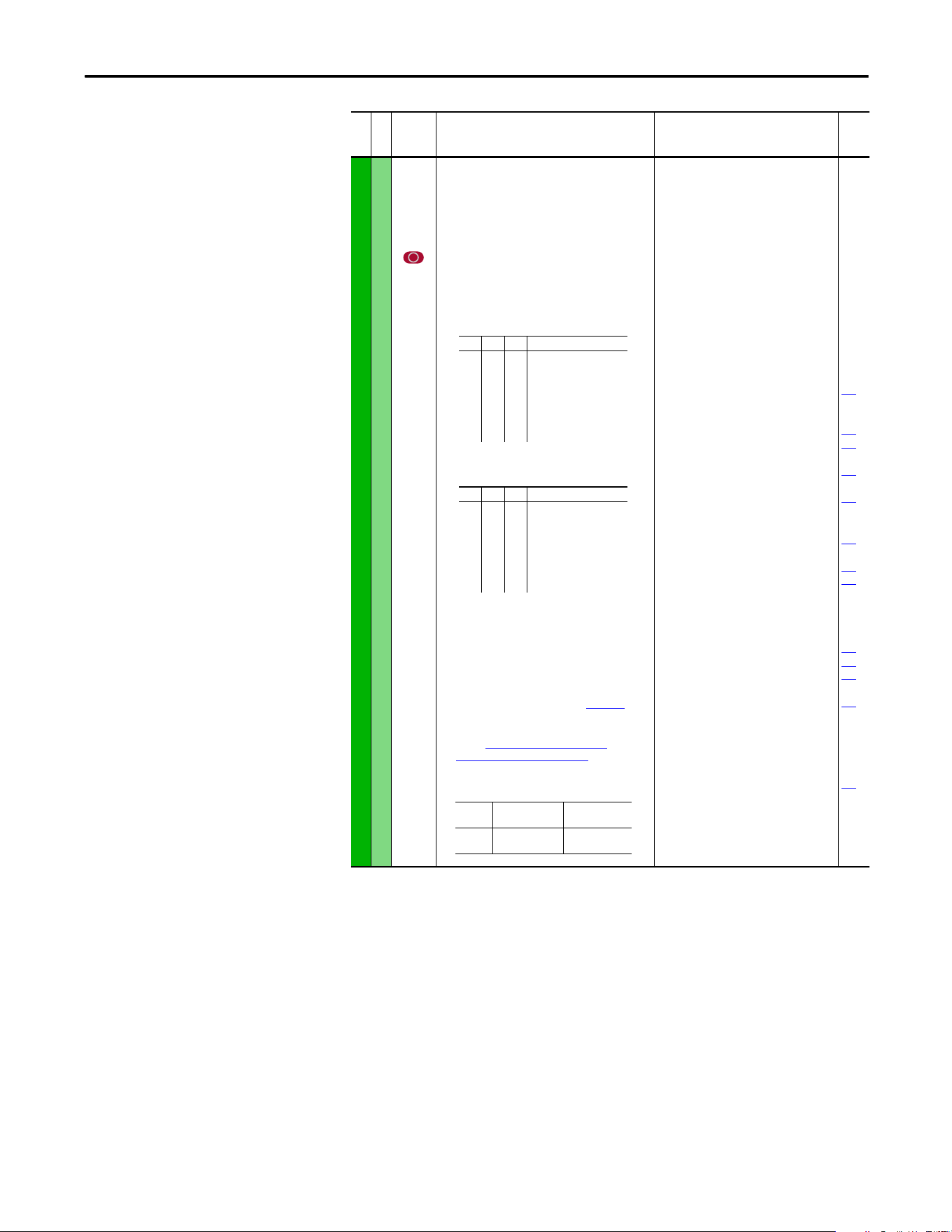
Rockwell Automation Publication 20A-UM001P-EN-P - February 2018 67
Programming and Parameters Chapter 1
INPUTS and OUTPUTS (file J)
Digital Inputs
361
362
363
364
365
366
[Digital In1 Sel]
[Digital In2 Sel]
[Digital In3 Sel]
[Digital In4 Sel]
[Digital In5 Sel]
[Digital In6 Sel](7)
Selects the function for the digital inputs.
Important: Digital inputs are not designed to
work with a pulsed source.
(1)
When [Digital Inx Sel] is set to option 2 “Clear Faults”
the Stop button cannot be used to clear a fault
condition.
To access Preset Speed 1, set [Speed Ref A Sel] or
[Speed Ref B Sel] to “Preset Speed 1”.
(4)
Only Enhanced Control Drives.
(5)
Enhanced firmware revision V2.001 and later.
(6)
Opening an “Enable” input causes the motor to coast-
to-stop, ignoring any programmed Stop modes.
(7)
A dedicated hardware enable input is available via a
jumper selection. Refer to I/O Wiring Examples in the
PowerFlex 70 Adjustable Frequency AC Drive
Installation Instructions, publication 20A-IN009.
(8)
Configures the input to command a transition between
the Manual/Auto or Auto/Manual speed references.
Refer to “Auto” Speed Sources on page 110 and
“Manual” Speed Sources on page 111 for details.
“Manual/Auto” (68) is similar to “Auto/Manual” (18)
except that the polarity is opposite.
Default:
Default:
Default:
Default:
Default:
Default:
Options:
4
5
18
15
16
17
0
1
2
3
4
5
6
7
8
9
10
11
12
13
14
15…17
18
19
20
21
22
23
24
25
26
27
28
29
30
31…33
34
35
36…40
41, 42
43
44
45
46
47…57
58
59
68
“Stop – CF”
(1)
“Start”
“Auto/ Manual”
“Speed Sel 1”
“Speed Sel 2”
“Speed Sel 3”
“Not Used”
“Enable”
(6)
“Clear Faults”
(1)
“Aux Fault”
“Stop – CF”
(1)
“Start”
(9)(11)
“Fwd/ Reverse”
(9)
“Run”
(10)
“Run Forward”
(10)
“Run Reverse”
(10)
“Jo g”
(9)
“Jog1”
(4)
“Jog Forward”
“Jog Reverse”
“Stop Mode B”
“Bus Reg Md B”
“Speed Sel 1-3”
(2)
“Auto/ Manual”
(8)
“Local”
“Acc2 and Dec2”
“Accel 2”
“Decel 2”
“MOP Inc”
(12)
“MOP Dec”
(12)
“Excl Link”
(12)
“PI Enable”
“PI Hold”
“PI Reset”
“Reserved”
“Precharge En”
(4)(12)
“Spd/Trq Sel1-3”
(3)(13)
“Jog 2”
(4)
“PI Invert”
(4)
“Reserved”
“UserSet Sel1-2”
(5)
“Run Level”
(5)(12)
“RunFwd Level”
(5)(12)
“RunRev Level”
(5)(12)
“Run w/Comm”
(5)(12)
“Reserved”
“Sync Enable”
(13)
“Traverse Ena”
(13)
“Manual/Auto”
(8)(14)
100
156
162
096
140
194
380
125
088
108
124
205
620
File J
Group
No.
Parameter Name and Description
(1)
Values
Related
(2)
321<– “Speed Sel 1…3”
0
0
0
0
1
1
1
1
0
0
1
1
0
0
1
1
0
1
0
1
0
1
0
1
Reference A - P90
Reference B - P93
Preset Speed 2 - P102
Preset Speed 3 - P103
Preset Speed 4 - P104
Preset Speed 5 - P105
Preset Speed 6 - P106
Preset Speed 7 - P107
(3)
3 2 1 <– “Spd/Trq Sel1…3”
0
0
0
0
1
1
1
1
0
0
1
1
0
0
1
1
0
1
0
1
0
1
0
1
Zero Torque
Spd Reg
Torque Reg
Min Spd/Trq
Max Spd/Trq
Sum Spd/Trq
Absolute
Zero Trq
Input
State
“A uto / Ma n ua l ”
(18)
“Manual/Auto”
(68)
Lo
Hi
Auto
Manual
Manual
Auto
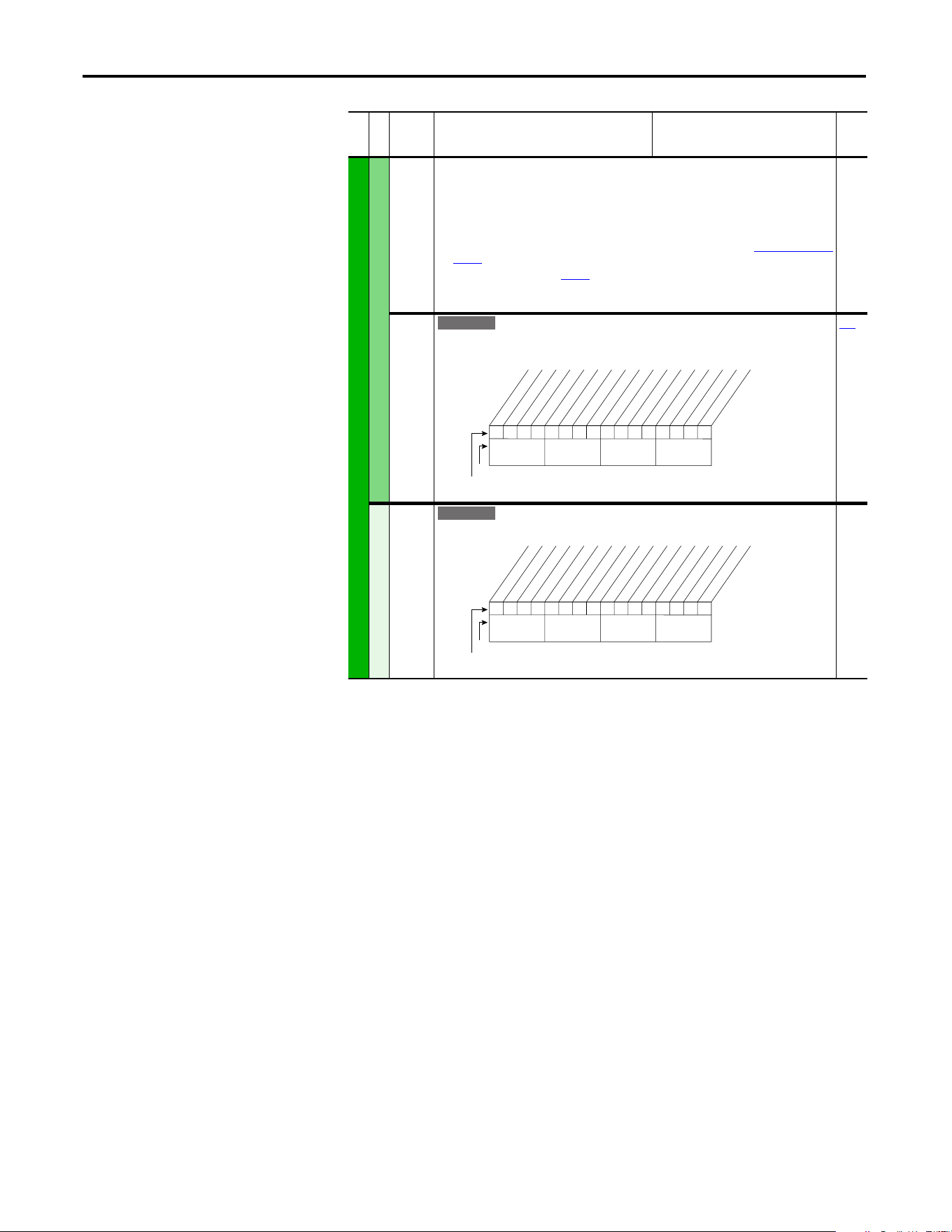
68 Rockwell Automation Publication 20A-UM001P-EN-P - February 2018
Chapter 1 Programming and Parameters
INPUTS and OUTPUTS (file J)
Digital Inputs
(9)
Typical 3-Wire Inputs - Requires that only 3-wire functions are chosen. Including 2-wire selections causes a
type 2 alarm.
(10)
Typical 2-Wire Inputs - Requires that only 2-wire functions are chosen. Including 3-wire selections causes a
type 2 alarm.
(11)
A “Dig In ConflictB” alarm occurs if a “Start” input is programmed without a “Stop” input. Type 2 Alarms -
Some digital input programming can cause conflicts that result in a Type 2 alarm. Example: [Digital In1 Sel]
set to 5 “Start” in 3-wire control and [Digital In2 Sel] set to 7 “Run” in 2-wire. Refer to Alarm Descriptions on
page 83 for information on resolving this type of conflict.
(12)
Refer to Option Definitions on page 70.
(13)
Enhanced firmware revision V3.002 and later.
(14)
Enhanced firmware revision V5.001 and later.
411 [DigIn DataLogic]
Provides data to the logical operations that are done with the digital inputs when parameter
056 option 9 “DigIn DatLog” is set to 1.
056
Digital Outputs
379 [Dig Out Setpt]
Controls output relays (CRx) when parameter 380 or 384 is set to option 30 “Param Cntl”.
File J
Group
No.
Parameter Name and Description
(1)
Values
Related
E C
000000xx000000xx
10 01234567891112131415
1 =Logical 1
0 =Logical 0
x =Reserved
Bit #
Factory Default Bit Values
In1 ANDdata
In2 ANDdata
In3 ANDdata
In4 ANDdata
In5 ANDdata
In6 ANDdata
In1 ORdata
In2 ORdata
In3 ORdata
In4 ORdata
In5 ORdata
In6 ORdata
Nibble 1Nibble 2Nibble 3Nibble 4
E C
0xx 0xxxxxxxxxxxx
10 01234567891112131415
1 =Enabled
0 =Disabled
x =Reserved
Bit #
Factory Default Bit Values
Digital Out1
Digital Out2
Nibble 1Nibble 2Nibble 3Nibble 4
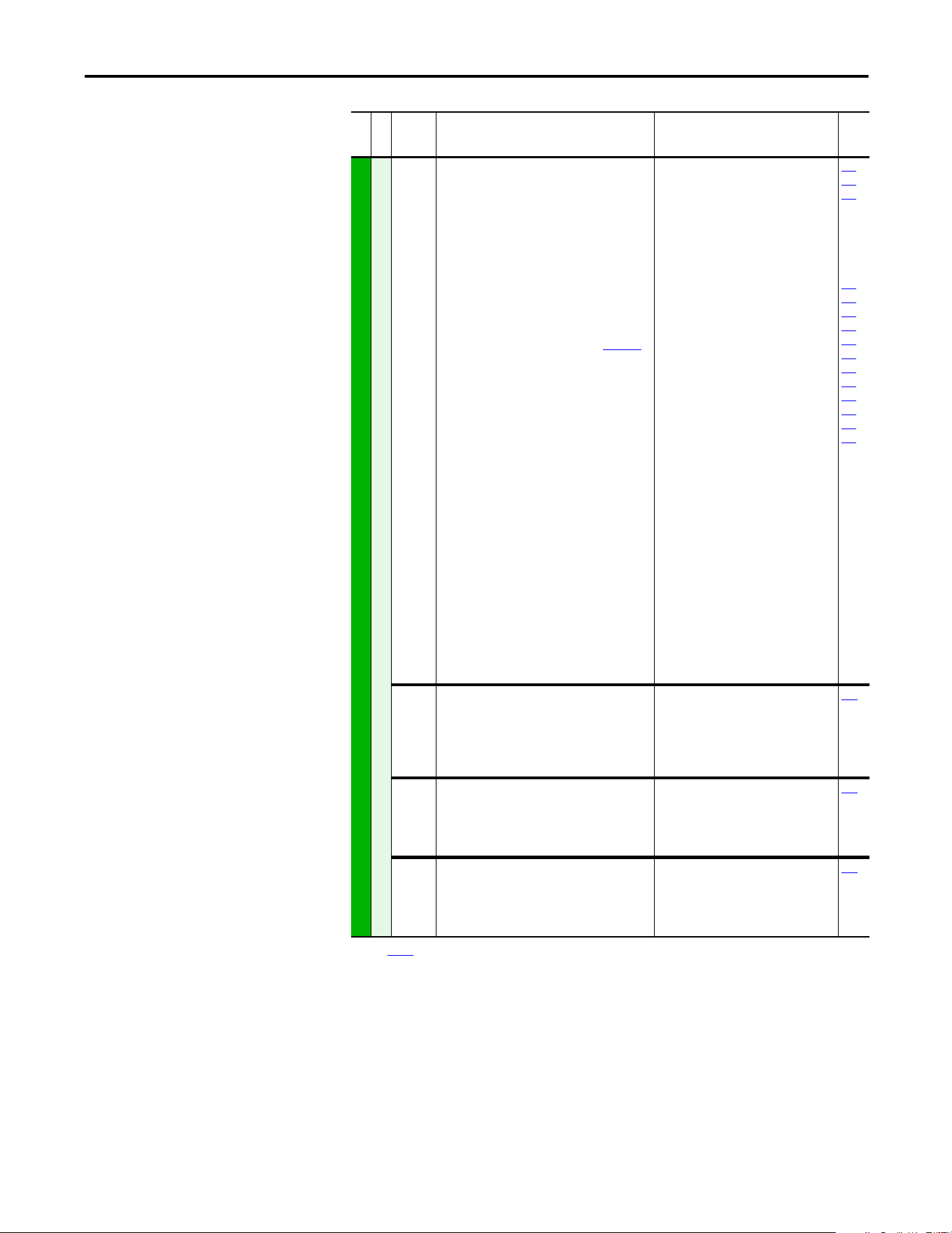
Rockwell Automation Publication 20A-UM001P-EN-P - February 2018 69
Programming and Parameters Chapter 1
INPUTS and OUTPUTS (file J)
Digital Outputs
380
384
[Digital Out1 Sel]
[Digital Out2 Sel]
Selects the drive status that energizes a (CRx)
output relay.
(1)
Any relay that is programmed as Fault or Alarm
energizes (pick up) when power is applied to drive
and deenergize (drop out) when a fault or alarm
exists. Relays selected for other functions energize
when that condition exists and deenergize when
that condition is removed.
Refer to I/O Wiring
Examples in the PowerFlex 70 Adjustable Frequency AC
Drive Installation Instructions, publication 20A-IN009.
(2)
Activation level is defined in [Dig Outx Level] below.
(3)
Only Enhanced Control Drives.
(4)
Enhanced firmware revision V3.002 and later.
(5)
Enhanced firmware revision V4.001 and later.
Default:
Options:
1
4
1
2
3
4
5
6
7
8
9
10
11
12
13
14
15
16
17
18
19
20
21
22
23
24
25
26
27
28
29
30
31…57
58
59
60
61
“Fault”
“Run”
“Fault”
(1)
“A la rm ”
(1)
“Ready”
“Run”
“Forward Run”
“Reverse Run”
“Auto Restart”
“Powerup Run”
“At Speed”
“At Freq”
(2)
“At Current”
(2)
“At Torque”
(2)
“At Temp”
(2)
“At Bus Volts”
(2)
“At PI Error”
(2)
“DC Braking”
“Curr Limit”
“Economize”
“Motor Overld”
“Power Loss”
“Input 1 Link”
“Input 2 Link”
“Input 3 Link”
“Input 4 Link”
“Input 5 Link”
“Input 6 Link”
“PI Enabled”
(3)
“PI Hold”
(3)
“Drive Overld”
(3)
“Param Cntl”
(3)
“Reserved”
“Manual Mode”
(4)
“Fast Braking”
(4)
“Reserved”
“Speed Fdbk”
(2)(5)
381
382
383
002
001
003
004
218
012
137
157
147
053
048
184
381
385
[Dig Out1 Level]
[Dig Out2 Level]
Sets the relay activation level for options 10...15
in [Digital Outx Sel]. Units are assumed to match
the above selection (for example, “At Freq” = Hz,
“At Torque” = Amps).
Default:
Min/Max:
Units:
0.0
0.0
0.0/819.2
0.1
380
382
386
[Dig Out1 OnTime]
[Dig Out2 OnTime]
Sets the “ON Delay” time for the digital outputs.
This is the time between the occurrence of a
condition and activation of the relay.
Default:
Min/Max:
Units:
0.0 s
0.0 s
0.0/600.0 s
0.1 s
380
383
387
[Dig Out1 OffTime]
[Dig Out2 OffTime]
Sets the “OFF Delay” time for the digital outputs.
This is the time between the disappearance of a
condition and de-activation of the relay.
Default:
Min/Max:
Units:
0.0 s
0.0 s
0.0/600.0 s
0.1 s
380
(1) See page 13 for Symbol Descriptions.
File J
Group
No.
Parameter Name and Description
(1)
Values
Related

70 Rockwell Automation Publication 20A-UM001P-EN-P - February 2018
Chapter 1 Programming and Parameters
Selected Option Definitions – [Analog Outx Sel], [Digital Inx Sel], and
[Digital Outx Sel]
Option Description Related
At Speed Relay changes state when drive has reached commanded speed. 380
Excl Link Links digital input to a digital output if the output is set to “Input 1-6 Link.” 361
Input 1…6 Link When Digital Output 1 is set to of these (for example, Input 3 Link) in conjunction with
Digital Input 3 set to “Excl Link,” the Digital Input 3 state (on/off) is echoed in the
Digital Output 1.
380
Manual Mode Either the HIM or I/O Terminal Block (analog input) has control of the speed reference. 380
MOP Dec Decrements speed reference as long as input is closed. 361
MOP Inc Increments speed reference as long as input is closed. 361
MtrTrqCurRef Torque producing current reference. 342
Param Cntl Parameter controlled analog output enables PLC to control analog outputs through
data links. Set in [AnlgX Out Setpt], parameters 377 and 378.
342
Param Cntl Parameter controlled digital output enables PLC to control digital outputs through
data links. Set in [Dig Out Setpt], parameter 379.
342
PI Reference Reference for PI block (see Process PI for Standard Control on page 113). 342
Precharge En Forces drive into precharge state. Typically controlled by auxiliary contact on the
disconnect at the DC input to the drive.
361
Run Level Provides a run level input. They do not require a transition for enable or fault, but a
transition is still required for a stop.
RunFwd Level
RunRev Level
Run w/Comm Enables the comms start bit to operate like a run with the run input on the terminal
block. Ownership rules apply.
SpdFdBk NoFilt Provides an unfiltered value to an analog output. The filtered version “Speed Fdbk”
includes a 125 ms filter.
342
Sync Enable The fiber feature Synchronized Speed Change has been enabled. Enables a coordinated
change in drive speeds to change machine speed.
622
Torque Est Calculated percentage of rated motor torque. 342
Traverse Enable The Traverse function has been enabled. This adds a triangle wave and square wave
modulation to the speed reference.
623
624
625
626
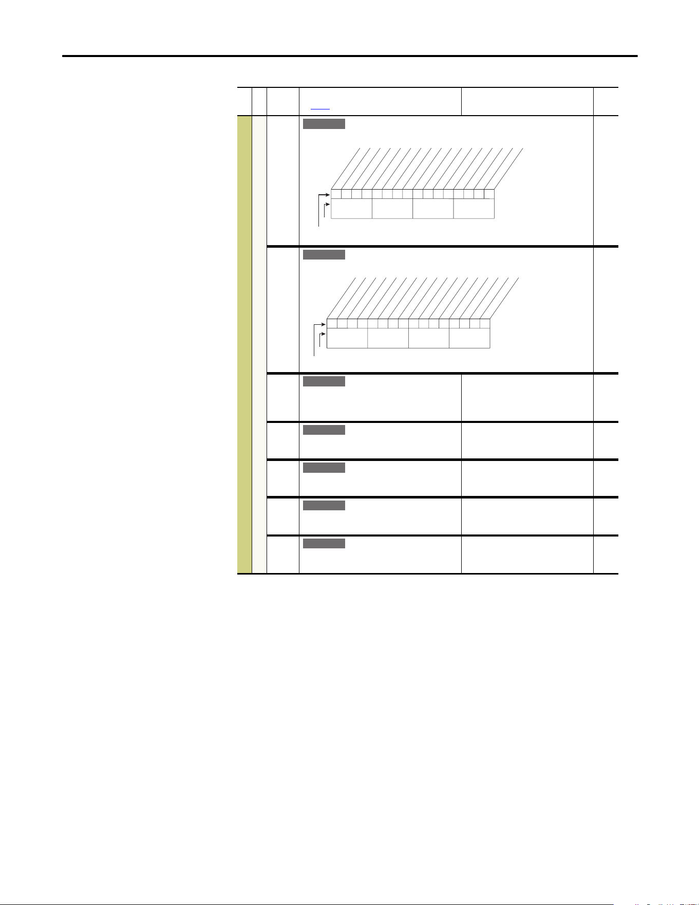
Rockwell Automation Publication 20A-UM001P-EN-P - February 2018 71
Programming and Parameters Chapter 1
Applications File (File K)
File K
Group
No.
Parameter Name and Description
See page 13 for Symbol Descriptions
Values
Related
APPLICATIONS (file K)
Fiber Functions
620 [Fiber Control]
Controls the Sync and Traverse functions.
621 [Fiber Status]
Status of Sync and Traverse functions.
Read Only
622 [Sync Time]
The time to ramp from the “held speed reference”
to the current speed reference, after the Sync input
is de-energized.
Default:
Min/Max:
Units:
0.0 s
0.0/3600.0 s
0.1 s
623 [Traverse Inc]
Sets the time period of increasing frequency.
Default:
Min/Max:
Units:
0.00 s
0.00/30.00 s
0.01 s
624 [Traverse Dec]
Sets the time period of decreasing frequency.
Default:
Min/Max:
Units:
0.00 s
0.00/30.00 s
0.01 s
625 [Max Traverse]
Sets the amplitude of the triangle wave speed
modulation.
Default:
Min/Max:
Units:
0.00 Hz
0.00/Maximum Speed
0.01 Hz
626 [P Jump]
Sets the amplitude of the square wave speed
modulation.
Default:
Min/Max:
Units:
0.00 Hz
0.00/Maximum Speed
0.01 Hz
E C v3
0xx 0xxxxxxxxxxxx
10 01234567891112131415
1 = Enabled
0 = Disabled
x = Reserved
Bit #
Factory Default Bit Values
Sync Enable
Traverse Ena
Nibble 1Nibble 2Nibble 3Nibble 4
E C v3
0000xxxxxxxxxxxx
10 01234567891112131415
1 = Condition True
0 = Condition False
x = Reserved
Bit #
Factory Default Bit Values
Sync Hold
Sync Ramp
Traverse On
Tra verse Dec
Nibble 1Nibble 2Nibble 3Nibble 4
E C v3
E C v3
E C v3
E C v3
E C v3
72 Rockwell Automation Publication 20A-UM001P-EN-P - February 2018
Chapter 1 Programming and Parameters
Parameter Cross
Reference – by Name
Parameter Name Number Group Page
Accel Mask 281 Masks and
Owners
60
Accel Owner 293 Masks and
Owners
61
Accel Time X 140, 141 Ramp Rates 40
Alarm Config 1 259 Alarms 58
Alarm X @ Fault 229, 230 Diagnostics 56
Analog In X Hi 322, 325 Analog Inputs 64
Analog In X Lo 323, 326 Analog Inputs 64
Analog In X Loss 324, 327 Analog Inputs 64
Analog In1 Value 16 Metering 22
Analog In2 Value 17 Metering 22
Analog Out1 Hi 343 Analog
Outputs
66
Analog Out1 Lo 344 Analog
Outputs
66
Analog Out1 Sel 342 Analog
Outputs
65
Anlg In Config 320 Analog Inputs 64
Anlg In Sqr Root 321 Analog Inputs 64
Anlg Out Absolut 341 Analog
Outputs
65
Anlg Out Config 340 Analog
Outputs
65
Anlg Out1 Scale 354 Analog
Outputs
66
Anlg Out1 Setpt 377 Analog
Outputs
66
Auto Rstrt Delay 175 Restart Modes 45
Auto Rstrt Tries 174 Restart Modes 45
AutoMan Cnfg 192 HIM Ref Config 48
Autotune 61 Torq Attributes 26
Autotune Torque 66 Torq Attributes 27
Break Frequency 72 Volts per Hertz 29
Break Voltage 71 Volts per Hertz 28
Bus Reg Gain 160 Stop/Brake
Modes
42
Bus Reg Kd 165 Stop/Brake
Modes
43
Bus Reg Ki 160 Stop/Brake
Modes
42
Bus Reg Kp 164 Stop/Brake
Modes
43
Bus Reg Mode X 161, 162 Stop/Brake
Modes
43
Commanded Freq 2 Metering 21
Commanded Torque 24 Metering 22
Compensation 56 Torq Attributes 25
Control Status 440 Torq Attributes 28
Control SW Ver 29 Drive Data 22
Current Lmt Gain 149 Load Limits 40
Current Lmt Sel 147 Load Limits 40
Current Lmt Val 148 Load Limits 40
Current Rate Limit 154 Load Limits 41
Data In XX 300…307 Datalinks 62
Data Out XX 310…317 Datalinks 62
DB Resistor Type 163 Stop/Brake
Modes
43
DB While Stopped 145 Stop/Brake
Modes
41
DC Brake Level 158 Stop/Brake
Modes
42
DC Brake Lvl Sel 157 Stop/Brake
Modes
42
DC Brake Time 159 Stop/Brake
Modes
42
DC Bus Memory 13 Metering 22
DC Bus Voltage 12 Metering 22
Decel Mask 282 Masks and
Owners
60
Decel Owner 294 Masks and
Owners
61
Decel Time X 142, 143 Ramp Rates 40
Dig In Status 216 Diagnostics 54
Dig Out Setpt 379 Digital Outputs 68
Dig Out Status 217 Diagnostics 54
Dig OutX Level 381, 385 Digital Outputs 69
Dig OutX OffTime 383, 387 Digital Outputs 69
Dig OutX OnTime 382, 386 Digital Outputs 69
DigIn DataLogic 411 Digital Inputs 68
Digital InX Sel 361…366 Digital Inputs 67
Digital OutX Sel 380, 384 Digital Outputs 69
Direction Mask 279 Masks and
Owners
60
Direction Mode 190 Direction
Config
48
Direction Owner 291 Masks and
Owners
61
DPI Data Rate 270 Comm Control 59
DPI Port Select 274 Comm Control 60
DPI Port Value 275 Comm Control 60
DPI Ref Select 298 Comm Control 60
Drive Alarm X 211, 212 Diagnostics 52
Drive Checksum 203 Drive Memory 50
Drive Logic Rslt 271 Comm Control 59
Drive OL Count 219 Diagnostics 54
Drive OL Mode 150 Load Limits 40
Drive Ramp Rslt 273 Comm Control 59
Drive Ref Rslt 272 Comm Control 59
Drive Status 1, 2 209, 210 Diagnostics 51
Drive Status 3 222 Diagnostics 55
Drive Temp 218 Diagnostics 54
Droop RPM @ FLA 152 Stop/Brake
Modes
41
Dyn UserSet Actv 206 Drive Memory 51
Dyn UsrSet Cnfg 204 Drive memory 50
Dyn UsrSet Sel 205 Drive memory 50
Elapsed kWh 14 Metering 22
Elapsed MWh 9 Metering 21
Elapsed Run Time 10 Metering 22
Enc Pos Fdbk 414 Speed
Feedback
29
Encoder PPR 413 Speed
Feedback
29
Encoder Speed 415 Speed
Feedback
29
Fault Amps 225 Diagnostics 55
Fault Bus Volts 226 Diagnostics 55
Fault Clear 240 Faults 57
Fault Clear Mode 241 Faults 57
Fault Clr Mask 283 Masks and
Owners
60
Fault Clr Owner 295 Masks and
Owners
61
Parameter Name Number Group Page
Rockwell Automation Publication 20A-UM001P-EN-P - February 2018 73
Programming and Parameters Chapter 1
Fault Config 1 238 Faults 53
Fault Frequency 224 Diagnostics 55
Fault X Code 243…249 Faults 58
Fault X Time 244…250 Faults 58
Fdbk Filter Sel 416 Speed
Feedback
29
Feedback Select 80 Spd Mode and
Limits
30
Fiber Control 620 Fiber Functions 71
Fiber Status 621 Fiber Functions 71
Flux Braking 166 Stop/Brake
Modes
44
Flux Current 5 Metering 21
Flux Current Ref 63 Torq Attributes 26
Flux Up Mode 57 Torq Attributes 25
Flux Up Time 58 Torq Attributes 25
Flying Start En 169 Restart Modes 45
Flying StartGain 170 Restart Modes 45
Gnd Warn Level 177 Restart Modes 47
HighRes Ref 308 Datalinks 62
Inertia Autotune 67 Torq Attributes 27
IR Voltage Drop 62 Torq Attributes 26
Ixo Voltage Drop 64 Torq Attributes 27
Jog Mask 278 Masks and
Owners
60
Jog Owner 290 Masks and
Owners
61
Jog Speed 100 Discrete
Speeds
34
Jog Speed 1 100 Discrete
Speeds
34
Jog Speed 2 108 Discrete
Speeds
34
Kf Speed Loop 447 Speed
Regulator
38
Ki Speed Loop 445 Speed
Regulator
38
Kp Speed Loop 446 Speed
Regulator
38
Language 201 Drive Memory 50
Last Stop Source 215 Diagnostics 53
Load Frm Usr Set 198 Drive Memory 49
Load Loss Level 187 Power Loss 47
Load Loss Time 188 Power Loss 47
Logic Mask Act 598 Security 63
Local Mask 285 Masks and
Owners
60
Local Owner 297 Masks and
Owners
62
Logic Mask 276 Masks and
Owners
60
Man Ref Preload 193 HIM Ref Config 48
Max Traverse 625 Fiber Functions 71
Maximum Freq 55 Torq Attributes 24
Maximum Speed 82 Spd Mode and
Limits
30
Maximum Voltage 54 Torq Attributes 24
Minimum Speed 81 Spd Mode and
Limits
30
MOP Frequency 11 Metering 22
MOP Mask 284 Masks and
Owners
61
MOP Owner 296 Masks and
Owners
61
Parameter Name Number Group Page
MOP Rate 195 MOP Config 49
Motor Cntl Sel 53 Torq Attributes 24
Motor Fdbk Type 412 Speed
Feedback
29
Motor NP FLA 42 Motor Data 23
Motor NP Hertz 43 Motor Data 23
Motor NP Power 45 Motor Data 23
Motor NP RPM 44 Motor Data 23
Motor NP Volts 41 Motor Data 23
Motor OL Count 220 Diagnostics 54
Motor OL Factor 48 Motor Data 23
Motor OL Hertz 47 Motor Data 23
Motor OL Mode 50 Motor Data 24
Motor Poles 49 Motor Data 23
Motor Type 40 Motor Data 23
Mtr NP Pwr Units 46 Motor Data 23
Mtr OL Trip Time 221 Diagnostics 54
Neg Torque Limit 437 Torq Attributes 28
Notch Filter K 420 Speed
Feedback
29
Notch FilterFreq 419 Speed
Feedback
29
Output Current 3 Metering 21
Output Freq 1 Metering 21
Output Power 7 Metering 21
Output Powr Fctr 8 Metering 21
Output Voltage 6 Metering 21
Overspeed Limit 83 Spd Mode and
Limits
30
P Jump 626 Fiber Functions 71
Param Access Lvl 196 Drive Memory 49
PI BW Filter 139 Process PI 37
PI Configuration 124 Process PI 35
PI Control 125 Process PI 36
PI Deriv Time 459 Process PI 37
PI Error Meter 137 Process PI 37
PI Fdback Meter 136 Process PI 37
PI Feedback Hi 462 Process PI 38
PI Feedback Lo 463 Process PI 38
PI Feedback Sel 128 Process PI 36
PI Integral Time 129 Process PI 36
PI Lower Limit 131 Process PI 36
PI Output Meter 138 Process PI 37
PI Preload 133 Process PI 37
PI Prop Gain 130 Process PI 36
PI Reference Hi 460 Process PI 38
PI Reference Lo 461 Process PI 38
PI Reference Sel 126 Process PI 36
PI Ref Meter 135 Process PI 37
PI Setpoint 127 Process PI 36
PI Status 134 Process PI 37
PI Upper Limit 132 Process PI 37
Pos Torque Limit 436 Torq Attributes 28
Port Mask Act 595 Security 63
Power Loss Mode 184 Power Loss 47
Power Loss Time 185 Power Loss 47
Power Up Marker 242 Faults 57
Powerup Delay 167 Restart Modes 44
Preset Speed X 101…107 Discrete
Speeds
34
PWM Frequency 151 Load Limits 40
Parameter Name Number Group Page
74 Rockwell Automation Publication 20A-UM001P-EN-P - February 2018
Chapter 1 Programming and Parameters
Ramped Speed 22 Metering 22
Rated Amps 28 Drive Data 22
Rated kW 26 Drive Data 22
Rated Volts 27 Drive Data 22
Reference Mask 280 Masks and
Owners
60
Reference Owner 292 Masks and
Owners
61
Regen Power Lim 153 Load Limits 41
Reset Meters 200 Drive Memory 49
Reset To Defalts 197 Drive Memory 49
Rev Speed Limit 454 Spd Mode and
Limits
31
Run Boost 70 Volts per Hertz 28
S Curve % 146 Ramp Rates 40
Save HIM Ref 192 HIM Ref Config 48
Save MOP Ref 194 MOP Config 49
Save To User Set 199 Drive Memory 49
Scale1 In Hi 476 Scaled Blocks 58
Scale1 In Lo 477 Scaled Blocks 58
Scale1 In Value 478 Scaled Blocks 58
Scale2 In Hi 482 Scaled Blocks 58
Scale2 In Lo 483 Scaled Blocks 58
Scale2 In Value 484 Scaled Blocks 58
Shear Pin Time 189 Load Limits 41
Skip Freq Band 87 Spd Mode and
Limits
31
Skip Frequency X 84…86 Spd Mode and
Limits
31
Sleep Level 182 Restart Modes 47
Sleep Time 183 Restart Modes 47
Sleep Wake Mode 178 Restart Modes 46
Sleep Wake Ref 179 Restart Modes 47
Slip Comp Gain 122 Slip Comp 35
Slip RPM @ FLA 121 Slip Comp 35
Slip RPM Meter 123 Slip Comp 35
Spd Err Filt BW 448 Speed
Regulator
38
Speed Desired BW 449 Speed
Regulator
39
Speed Feedback 25 Metering 22
Speed Loop Meter 451 Speed
Regulator
39
Speed Mode 80 Spd Mode and
Limits
30
Speed Ref X Hi 91, 94 Speed
Reference
32
Speed Ref X Lo 92, 95 Speed
Reference
32
Speed Ref X Sel 90, 93 Speed
Reference
32
Speed Reference 23 Metering 22
Speed Ref Source 213 Diagnostics 53
Speed/Torque Mod 88 Spd Mode and
Limits
31
Start At Powerup 168 Restart Modes 44
Start Inhibits 214 Diagnostics 53
Start Mask 277 Masks and
Owners
60
Start Owner 289 Masks and
Owners
61
Start/Acc Boost 69 Volts per Hertz 28
Parameter Name Number Group Page

Rockwell Automation Publication 20A-UM001P-EN-P - February 2018 75
Programming and Parameters Chapter 1
Status X @ Fault 227, 228 Diagnostics 55
Status 3 @ Fault 223 Diagnostics 55
Stop/Brk Mode X 155, 156 Stop/Brake
Modes
41
Stop Owner 288 Masks and
Owners
61
SV Boost Filter 59 Torq Attributes 25
Sync Time 622 Fiber Functions 71
TB Man Ref Hi 97 Speed
Reference
33
TB Man Ref Lo 98 Speed
Reference
33
TB Man Ref Sel 96 Speed
Reference
33
Tes tp oi nt X Data 235, 237 Diagnostics 57
Tes tp oi nt X Sel 234, 236 Diagnostics 57
Torq Current Ref 441 Torq Attributes 28
Torque Current 4 Metering 21
Torque Estimate 15 Metering 22
Torque Perf Mode 53 Torq Attributes 24
Torque Ref A Hi 428 Torq Attributes 27
Torque Ref A Lo 429 Torq Attributes 27
Torque Ref A Sel 427 Torq Attributes 27
Torque Setpoint1 435 Torq Attributes 27
Total Inertia 450 Speed
Regulator
39
Traverse Dec 624 Fiber Functions 71
Traverse Inc 623 Fiber Functions 71
Trim % Setpoint 116 Speed Trim 34
Trim Hi 119 Speed Trim 35
Trim In Select 117 Speed Trim 34
Trim Lo 120 Speed Trim 35
Trim Out Select 118 Speed Trim 35
Voltage Class 202 Drive Memory 50
Wake Level 180 Restart Modes 47
Wake Time 181 Restart Modes 47
Write Mask Act 597 Security 63
Write Mask Cfg 596 Security 63
Parameter Name Number Group Page

76 Rockwell Automation Publication 20A-UM001P-EN-P - February 2018
Chapter 1 Programming and Parameters
Notes:
Rockwell Automation Publication 20A-UM001P-EN-P - February 2018 77
Chapter 2
Troubleshooting
This chapter provides information for troubleshooting the PowerFlex 70 drive. It
includes a list and descriptions of drive faults (with possible solutions, when
applicable) and alarms.
Faults and Alarms
A fault is a condition that stops the drive. There are three fault types.
An alarm is a condition that, if left untreated, can stop the drive. There are two
alarm types.
Drive Status
The condition or state of the drive is constantly monitored. Any changes are
indicated through the LEDs and/or the HIM (if present).
Topic Page
Faults and Alarms 77
Drive Status 77
Clearing Alarms 82
Testpoint Codes and Functions 85
Common Symptoms and Corrective Actions 86
Type Fault Description
1 Auto-reset run When this type of fault occurs, and [Auto Rstrt Tries] (see page 45
) is set to a value greater
than “0,” a user-configurable timer, [Auto Rstrt Delay] (see page 45) begins. When the
timer reaches zero, the drive attempts to automatically reset the fault. If the condition that
caused the fault is no longer present, the fault is reset and the drive is restarted. Drive must
remain in Run state. If Stop is initiated, Restart function is aborted.
2 Non-resettable This type of fault normally requires drive or motor repair. The cause of the fault must be
corrected before the fault can be cleared. The fault is reset on powerup after repair.
3 User configurable These faults can be enabled/disabled to annunciate or ignore a fault condition.
Type Alarm Description
1 User configurable These alarms can be enabled or disabled by using [Alarm Config 1] on page 58
.
2 Non-configurable These alarms are always enabled.
78 Rockwell Automation Publication 20A-UM001P-EN-P - February 2018
Chapter 2 Troubleshooting
HIM Indication
The LCD and LED HIMs also provide visual notification of a fault or alarm
condition.
Manually Clearing Faults
Condition Display
Drive is indicating a fault.
The LCD HIM immediately reports the fault condition by displaying the following
information:
· “Faulted” appears in the status line
· Fault number
· Fault name
· Time that has passed since the fault occurred
Press Esc to regain HIM control.
The LED HIM reports the fault condition by displaying the specific fault code.
LCD HIM
LED HIM
Drive is indicating an alarm.
The LCD HIM immediately reports the alarm condition by displaying the following
information:
· Alarm name (Type 2 alarms only)
· Alarm bell graphic
LCD HIM
LED HIM
No indication.
Step Keys
1. Press Esc to acknowledge the fault. The fault information is removed so that you
can use the HIM.
2. Address the condition that caused the fault.
The cause must be corrected before the fault can be cleared.
3. After corrective action has been taken, clear the fault by one of these methods:
· Press Stop.
· Cycle power to the drive.
· Set parameter 240 [Fault Clear] to “1.”
· “Clear Faults” on the HIM Diagnostic menu.
F-> Faulted Auto
0.0
Hz
Main Menu:
Diagnostics
Parameter
— Fault — F 5
OverVoltage
Time Since Fault
0000:23:52
F-> Power Loss Auto
0.0
Hz
Main Menu:
Diagnostics
Parameter
Device Select
Esc

Rockwell Automation Publication 20A-UM001P-EN-P - February 2018 79
Troubleshooting Chapter 2
Fault Descriptions
Tab le 1 provides a list of fault messages, descriptions of the cause of the fault, and
corrective action to fix the fault.
Table 1 - Fault Types, Descriptions, and Actions
Fault No.
Type
(1)
Description Action
Analog In Loss 29 1
3
An analog input is configured to fault on signal
loss. A signal loss has occurred.
Configure with [Anlg In X Loss] on page 64
.
1. Check the parameters.
2. Check for broken/loose
connections at inputs.
Anlg Cal Chksum 108 The checksum read from the analog calibration
data does not match the checksum that is
calculated.
Replace the drive.
Auto Rstrt Tries 33 3 Drive unsuccessfully attempted to reset a fault
and resume running for the programmed
number of [Flt RstRun Tries].
Enable/Disable with [Fault Config 1] on page 53.
Correct the cause of the fault and
manually clear.
AutoTune Aborted 80 Autotune function was canceled by the user or a
fault occurred.
Restart the procedure.
Cntl Bd Overtemp 55 The temperature sensor on the Main Control
Board detected excessive heat.
1. Check Main Control Board fan.
2. Check surrounding air
temperature.
3. Verify proper mounting/
cooling.
Auxiliary Input 2 1 Auxiliary input interlock is open. Check remote wiring.
DB Resistance 69 The resistance of the internal DB unit is out of
range.
Replace the resistor.
Decel Inhibit 24 3 The drive is not following a commanded
acceleration or deceleration because it is
attempting to limit bus voltage.
1. Verify that input voltage is
within drive specified limits.
2. Verify that system ground
impedance follows proper
grounding techniques.
3. Disable bus regulation and/or
add dynamic brake resistor
and/or extend deceleration
time.
Drive OverLoad 64 Drive rating of 110% for 1 minute or 150% for 3
seconds has been exceeded.
Reduce load or extend Accel Time.
Drive Powerup 49 No fault is displayed. Used as a Power Up Marker in the Fault Queue indicating that the
drive power has been cycled.
Enable Hardware 111 Safe-Off board is not installed and pins 3 and 4 of
the Safe-Off Connector are not jumpered.
Install Safe-Off board or jumper
pins 3 and 4.
If Safe-Off board is installed, verify that the
hardware enable jumper is removed.
Locate and remove the enable
jumper on the main control board.
Refer to DriveGuard Safe-Off
Option (Series B) for PowerFlex 40P
and PowerFlex 70 AC Drives,
publication PFLEX-UM003
, for
instructions and location.
Safe-Off board has failed. Replace Safe-Off board.
Hardware enable circuitry failed. Replace control board.
Encoder Loss 91 One or both encoder channel signals is missing. 1. Check Wiring.
2. Replace encoder.
Encoder Quad Err 90 Both encoder channels changed state within one
clock cycle.
1. Check for externally induced
noise.
2. Replace encoder.
Hardware Fault 93 Hardware enable is disabled (jumpered high) but
logic pin is still low.
1. Check jumper.
2. Replace Main Control Board.
Excessive Load 79 Motor did not come up to speed in the allotted
time during autotune.
1. Uncouple load from motor.
2. Repeat Autotune.
Faults Cleared 52 No fault displayed. Used as a marker in the Fault Queue indicating that the fault clear
function was performed.
E C v2
E C
E C v2
E C v2
80 Rockwell Automation Publication 20A-UM001P-EN-P - February 2018
Chapter 2 Troubleshooting
Fatal Faults 900…
930
2 Diagnostic code indicating a drive malfunction. 1. Cycle power.
2. Replace Main Control Board.
3. Contact Tech Support.
Flt QueueCleared 51 No fault displayed. Used as a marker in the Fault Queue indicating that the clear queue
function was performed.
FluxAmpsRef Rang 78 The value for flux amps determined by the
Autotune procedure exceeds the programmed
[Motor NP FLA].
1. Reprogram [Motor NP FLA]
with the correct motor
nameplate value.
2. Repeat Autotune.
Ground Fault 13 1 A current path to earth ground greater than 25%
of drive rating.
Check the motor and external
wiring to the drive output
terminals for a grounded
condition.
Heatsink LowTemp 10 1 Annunciates a too low temperature case or an
open NTC (heatsink temperature sensing device)
circuit.
1. Verify ambient temperature.
2. In cold ambient temperatures,
add space heaters.
3. Check connections to NTC.
Heatsink OvrTemp 8 1 Heatsink temperature exceeds 100% of [Drive
Tem p].
1. Verify that maximum ambient
temperature has not been
exceeded.
2. Check fan.
3. Check for excess load.
HW OverCurrent 12 1 The drive output current has exceeded the
hardware current limit.
1. Check output of drive or motor
for shorts.
2. Check programming.
3. Check for excess load, improper
DC boost setting, DC brake volts
set too high, or other causes of
excess current.
Incompact MCB-PB 106 2 Drive rating information that is stored on the
power board is incompatible with the main
control board.
Load compatible version files into
drive.
Input Phase Loss 17 The DC bus ripple has exceeded a preset level. Check incoming power for a
missing phase/blown fuse.
IR Volts Range 77 “Calculate” is the autotune default and the value
that is determined by the autotune procedure for
IR Drop Volts is not in the range of acceptable
values.
Re-enter motor nameplate data.
IXo VoltageRange 87 Voltage calculated for motor inductive
impedance exceeds 25% of [Motor NP Volts].
1. Check for proper motor sizing.
2. Check for correct programming
of [Motor NP Volts], parameter
41.
3. Additional output impedance
can be required.
Load Loss 15 Drive output torque current is below [Load Loss
Level] for a time period greater than [Load Loss
time].
1. Verify connections between
motor and load.
2. Verify level and time
requirements.
Motor OverLoad 7 1
3
Internal electronic overload trip.
Enable/Disable with [Fault Config 1] on page 53
.
An excessive motor load exists.
Reduce load so drive output
current does not exceed the current
set by [Motor NP FLA]. If enabled,
check level of flux braking in
parameter P549 [Flux Braking %].
Motor Thermistor 16 Thermistor output is out of range. 1. Verify that thermistor is
connected.
2. Motor is overheated. Reduce
load.
Overspeed Limit 25 1 Functions such as Slip Compensation or Bus
Regulation have attempted to add an output
frequency adjustment greater than that
programmed in [Overspeed Limit].
Remove excessive load or
overhauling conditions or increase
[Overspeed Limit].
Table 1 - Fault Types, Descriptions, and Actions (continued)
Fault No.
Type
(1)
Description Action
E C v2
E C v2
E C v2
E C v2
E C
Rockwell Automation Publication 20A-UM001P-EN-P - February 2018 81
Troubleshooting Chapter 2
OverVoltage 5 1 DC bus voltage exceeded maximum value. Monitor the AC line for high line
voltage or transient conditions. Bus
overvoltage can also be caused by
motor regeneration. Extend the
decel time or install dynamic brake
option.
Parameter Chksum 100 2 The checksum read from the board does not
match the checksum that is calculated.
1. Restore defaults.
2. Reload User Set if used.
Params Defaulted 48 The drive was commanded to write default
values to EEPROM.
1. Clear the fault or cycle power to
the drive.
2. Program the drive parameters
as needed.
Phase U to Grnd 38 A phase to ground fault has been detected
between the drive and motor in this phase.
1. Check the wiring between the
drive and motor.
2. Check motor for grounded
phase.
3. Replace drive.
Phase V to Grnd 39
Phase W to Grnd 40
Phase UV Short 41 Excessive current has been detected between
these two output terminals.
1. Check the motor and drive
output terminal wiring for a
shorted condition.
2. Replace drive.
Phase VW Short 42
Phase UW Short 43
Port 1…5 DPI Loss 81…
85
DPI port stopped communicating.
A SCANport device was connected to a drive
operating DPI devices at 500k baud.
1. If adapter was not intentionally
disconnected, check wiring to
the port. Replace wiring, port
expander, adapters, Main
Control Board, or complete
drive as required.
2. Check HIM connection.
3. If an adapter was intentionally
disconnected and the [Logic
Mask] bit for that adapter is set
to “1”, this fault occurs. To
disable this fault, set the [Logic
Mask] bit for the adapter to “0.”
Port 1…5 Adapter 71…
75
The communications card has a fault. Check DPI device event queue and
corresponding fault information
for the device.
Power Loss 3 1
3
DC bus voltage remained below trigger of
nominal for longer than [Power Loss Time].
Enable/Disable with [Fault Config 1] on page 53
.
Monitor the incoming AC line for
low voltage or line power
interruption.
Pwr Brd Chksum1 104 The checksum read from the EEPROM does not
match the checksum that is calculated from the
EEPROM data.
Clear the fault or cycle power to the
drive.
Pwr Brd Chksum2 105 2 The checksum read from the board does not
match the checksum that is calculated.
1. Cycle power to the drive.
2. If problem persists, replace
drive.
Power Down Csum 112 EEPROM data is corrupt on drive powerup. Clear the fault or cycle power to the
drive.
Power Unit 70 One or more of the output transistors were
operating in the active region instead of
desaturation. This can be caused by excessive
transistor current or insufficient base drive
voltage.
1. Check for damaged output
transistors.
2. Replace drive.
Replaced MCB-PB 107 2 Main Control Board was replaced and parameters
were not programmed.
1. Restore defaults.
2. Reprogram parameters.
Shear Pin 63 3 Programmed [Current Lmt Val] has been
exceeded. Enable/Disable with [Fault Config 1]
on page 53
.
Check load requirements and
[Current Lmt Val] setting.
SW OverCurrent 36 1 Drive output current has exceeded the 1 ms
current rating. This rating is greater than the
3-second current rating and less than the
hardware overcurrent fault level. It is typically
200…250% of the drive continuous rating.
Check for excess load, improper DC
boost setting. DC brake volts set
too high.
If enabled, check level of flux
braking in parameter P549 [Flux
Braking %].
Table 1 - Fault Types, Descriptions, and Actions (continued)
Fault No.
Type
(1)
Description Action
82 Rockwell Automation Publication 20A-UM001P-EN-P - February 2018
Chapter 2 Troubleshooting
Table 2 - Fault Cross-reference
Clearing Alarms
Alarms are automatically cleared when the condition that caused the alarm is no
longer present.
Trnsistr OvrTemp 9 1 Output transistors have exceeded their maximum
operating temperature.
1. Verify that maximum ambient
temperature has not been
exceeded.
2. Check fan.
3. Check for excessive load.
UnderVoltage 4 1
3
DC bus voltage fell below the minimum value.
Standard Control:
• 509V DC at 600V input
• 407V DC at 400/480V input
• 204V DC at 200/240V input
Enhanced Control:
• 375V DC at 600V input
• 300V DC at 400/480 input
• 160V DC at 200/240V input
Enable/Disable with [Fault Config 1] on page 53
.
Monitor the incoming AC line for
low voltage or power interruption.
UserSet1 Chksum 101 2 The checksum read from the user set does not
match the checksum that is calculated.
Re-save user set.
UserSet2 Chksum 102 2
UserSet3 Chksum 103 2
(1) See page 77 for a description of fault types.
No.
(1)
(1) Fault numbers that are not listed are reserved for future use.
Fault No.
(1)
Fault No.
(1)
Fault
2 Auxiliary Input 38 Phase U to Grnd 80 AutoTune Aborted
3 Power Loss 39 Phase V to Grnd 81…86 Port 1…6 DPI Loss
4 UnderVoltage 40 Phase W to Grnd 87 IXo VoltageRange
5 OverVoltage 41 Phase UV Short 90 Encoder Quad Error
7 Motor Overload 42 Phase VW Short 91 Encoder Loss
8 Heatsink OvrTemp 43 Phase UW Short 93 Hardware Fault
9 Trnsistr OvrTemp 48 Params Defaulted 100 Parameter Chksum
10 Heatsink LowTemp 49 Drive Powerup 101 UserSet1 Chksum
12 HW OverCurrent 51 Flt QueueCleared 102 UserSet2 Chksum
13 Ground Fault 52 Faults Cleared 103 UserSet3 Chksum
15 Load Loss 55 Cntl Bd Overtemp 104 Pwr Brd Chksum1
16 Motor Thermistor 63 Shear Pin 105 Pwr Brd Chksum2
17 Input Phase Loss 64 Drive Overload 106 Incompat MCB-PB
24 Decel Inhibit 69 DB Resistance 107 Replaced MCB-PB
25 OverSpeed Limit 70 Power Unit 108 Anlg Cal Chksum
29 Analog In Loss 71…75 Port 1…5 Adapter 111 Enable Hardware
33 Auto Rstrt Tries 77 IR Volts Range 112 Power Down Csum
36 SW OverCurrent 78 FluxAmpsRef Rang 900…930 Fatal Faults
79 Excessive Load
Table 1 - Fault Types, Descriptions, and Actions (continued)
Fault No.
Type
(1)
Description Action
Rockwell Automation Publication 20A-UM001P-EN-P - February 2018 83
Troubleshooting Chapter 2
Alarm Descriptions
Tab le 3 provides a list of alarm messages and descriptions of the cause of the
alarm.
Table 3 - Alarm Descriptions and Actions
Alarm
No.
Type
(1)
Description
Analog in Loss 5 1 An analog input is configured for “Alarm” on signal loss and signal loss has occurred.
Bipolar
Conflict
20 2 Parameter 190 [Direction Mode] is set to “Bipolar” or “Reverse Dis” and one or more of the
following digital input functions is configured:
“Fwd/Reverse”, “Run Forward”, “Run Reverse”, “Jog Forward”, or “Jog Reverse”.
Decel Inhibit 10 1 Drive is being inhibited from decelerating.
Dig In
ConflictA
17 2 Digital input functions are in conflict. Combinations marked with an “X” will cause an alarm.
Dig In
ConflictB
18 2 A digital Start input has been configured without a Stop input or other functions are in
conflict. Combinations that conflict are marked with an “X” and will cause an alarm.
Dig In
ConflictC
19 2 More than one physical input has been configured to the same input function. Multiple
configurations are not allowed for the following input functions.
Drive OL Level
1
8 1 The calculated IGBT temperature requires a reduction in PWM frequency. If [Drive OL Mode] is
disabled and the load is not reduced, an overload fault eventually occurs.
Drive OL Level
2
9 1 The calculated IGBT temperature requires a reduction in Current Limit. If [Drive OL Mode] is
disabled and the load is not reduced, an overload fault eventually occurs.
FluxAmpsRef
Rang
26 2 The calculated or measured Flux Amps value is not within the expected range. Verify motor
data and rerun motor tests.
Ground Warn 15 1 Ground current has exceeded the level set in [Gnd Warn Level].
In Phase Loss 13 1 The DC bus ripple has exceeded the level in [Phase Loss Level].
IntDBRes
OvrHeat
6 1 The drive has temporarily disabled the DB regulator because the resistor temperature has
exceeded a predetermined value.
Acc2/Dec2 Accel 2 Decel 2 Jog Jog Fwd Jog Rev Fwd/Rev
Acc2 / Dec2 X X
Accel 2 X
Decel 2 X
Jog X X
Jog Fwd X X
Jog Rev X X
Fwd / Rev X X
Start Stop–CF Run Run Fwd Run Rev Jog Jog Fwd Jog Rev Fwd/Rev
Start X X X X X
Stop–CF
Run X X X X X
Run Fwd X X X X
Run Rev X X X X
Jog X X
Jog Fwd X X
Jog Rev X X
Fwd / Rev X X
Forward/Reverse Run Reverse Bus Regulation Mode B
Speed Select 1 Jog Forward Acc2 / Dec2
Speed Select 2 Jog Reverse Accel 2
Speed Select 3 Run Decel 2
Run Forward Stop Mode B
E C v2
E C v2

84 Rockwell Automation Publication 20A-UM001P-EN-P - February 2018
Chapter 2 Troubleshooting
IR Volts Range 25 2 The drive auto tuning default is “Calculate” and the value that is calculated for IR Drop Volts is
not in the range of acceptable values. This alarm clears when all motor nameplate data is
properly entered.
IXo
VoltageRange
28 2 Motor leakage inductance is out of range.
Load Loss 14 Output torque current is below [Load Loss Level] for a time period greater than [Load Loss
time].
MaxFreq
Conflict
23 2 The sum of [Maximum Speed] and [Overspeed Limit] exceeds [Maximum Freq]. Raise
[Maximum Freq] or lower [Maximum Speed]
and/or [Overspeed Limit] so that the sum is less than or equal to [Maximum Freq].
Motor
Thermistor
12 [Fault Config 1] or [Alarm Config 1] Bit 7 “Motor Therm” is enabled and the analog Input
voltage is <0.2 Volts or >5.0 Volts.
Motor Type
Cflct
21 2 [Motor Type] has been set to “Synchr Reluc” or “Synchr PM” and one or more of the following
exist:
· [Torque Perf Mode] = “Sensrls Vect,” “SV Economize” or “Fan/Pmp V/Hz.”
· [Flux Up Time] is greater than 0.0 s
· [Speed Mode] is set to “Slip Comp.”
· [Autotune] = “Static Tune” or “Rotate Tune.”
NP Hz Conflict 22 2 Fan/pump mode is selected in [Torq Perf Mode] and the ratio of [Motor NP Hertz] to
[Maximum Freq] is greater than 26.
Power Loss 3 1 Drive has sensed a power line loss.
Precharge
Active
1 1 Drive is in the initial DC bus precharge state.
PTC Conflict 31 [Fault Config 1] or [Alarm Config 1] Bit 7 “Motor Therm” is enabled and Analog In 1 is set to
milliamperes.
Sleep Config 29 2 Sleep/Wake configuration error. With [Sleep-Wake Mode] = “Direct,” possible causes include:
drive is stopped and [Wake Level] < [Sleep Level].“Stop=CF,” “Run,” “Run Forward,” or “Run
Reverse.” is not configured in [Digital Inx Sel].
Speed Ref Cflct 27 2 [Speed Ref x Sel] or [PI Reference Sel] is set to “Reserved”.
Start At
Powerup
4 1 [Start At Powerup] is enabled. The drive can start at any time within 10 seconds of drive
powerup.
TB Man Ref
Cflct
30 Occurs when:
· “Auto/Manual” is selected (default) for [Digital In3 Sel], parameter 363
and
· [TB Man Ref Sel], parameter 96 has been reprogrammed.
No other use for the selected analog input can be programmed.
Example: If [TB Man Ref Sel] is reprogrammed to “Analog In 2,” all of the factory default uses
for “Analog In 2” must be reprogrammed (such as parameters 90, 117, 128, and 179). See also
Auto/Manual Examples
on page 112.
To correct:
· Verify/reprogram the parameters that reference an analog input
or
· Reprogram [Digital In3] to another function or “Unused.”
UnderVoltage 2 1 The bus voltage has dropped below a predetermined value.
UserSet
Conflict
51 2 [Digital Inx Sel] values differ in different user sets.
VHz Neg Slope 24 2 [Torq Perf Mode] = “Custom V/Hz” and the V/Hz slope is negative.
Waking 11 1 The Wake timer is counting toward a value that will start the drive.
(1) See page 77 for a description of alarm types.
Table 3 - Alarm Descriptions and Actions (continued)
Alarm
No.
Type
(1)
Description
E C v2
E C v2
E C
E C
E C v2
E C
E C v2
E C v2
Rockwell Automation Publication 20A-UM001P-EN-P - February 2018 85
Troubleshooting Chapter 2
Table 4 - Alarm Cross Reference
Testpoint Codes and
Functions
Table 5 - Testpoint Codes and Functions
No.
(1)
(1) Alarm numbers that are not listed are reserved for future use.
Alarm No.
(1)
Alarm No.
(1)
Alarm
1 Precharge Active 12 Motor Thermistor 23 MaxFreq Conflict
2 UnderVoltage 13 In Phase Loss 24 VHz Neg Slope
3 Power Loss 14 Load Loss 25 IR Volts Range
4 Start At Powerup 15 Ground Warn 26 FluxAmpsRef Rang
5 Analog in Loss 17 Dig In ConflictA 27 Speed Ref Cflct
6 IntDBRes OvrHeat 18 Dig In ConflictB 28 Ixo Vlt Rang
8 Drive OL Level 1 19 Dig In ConflictC 29 Sleep Config
9 Drive OL Level 2 20 Bipolar Conflict 30 TB Man Ref Cflct
10 Decel Inhibit 21 Motor Type Cflct 31 PTC Conflict
11 Waking 22 NP Hz Conflict 51 UserSet Conflict
Code Selected in
[Testpoint x Sel]
Function Whose Value Is Displayed in
[Testpoint x Data]
1 DPI Error Status
2 Heatsink Temperature
3 Active Current Limit
4 Active PWM Frequency
5 Lifetime Megawatt Hours
(1)
(1) Use the equation below to calculate total Lifetime Megawatt Hours.
6 Lifetime Run Time
7 Lifetime Powered Up Time
8 Lifetime Power Cycles
9 Life Megawatt Hours Fraction
(1)
10 Life Megawatt Hours Fraction Units
(1)
11…99 Reserved for Factory Use
Value of Code 9
Value of Code 10
--------------------------------
0.1
Value of Code 5+ Total Lifetime MegaWatt Hours=
86 Rockwell Automation Publication 20A-UM001P-EN-P - February 2018
Chapter 2 Troubleshooting
Common Symptoms and
Corrective Actions
Tab le 6 through Ta bl e 12 describe the cause, status indication (if applicable), and
corrective action of common problem symptoms.
Table 6 - Drive Does Not Start from Start or Run Inputs Wired to the Terminal Block
Table 7 - Drive Does Not Start from HIM
Table 8 - Drive Does Not Respond to Changes in Speed Command
Causes Indication Corrective Action
Drive is faulted Flashing red
status light
Clear fault:
1. Press Stop.
2. Cycle the power.
3. Set [Fault Clear] to 1 (see page 53).
4. “Clear Faults” on the HIM Diagnostic menu.
Incorrect input wiring. Refer to PowerFlex 70
Adjustable Frequency AC Drive Installation
Instructions, publication 20A-IN009
, for wiring
examples.
· 2-wire control requires Run, Run Forward, Run
Reverse, or Jog input.
· 3-wire control requires Start and Stop inputs
· Jumper from terminal 7 to 8 is required.
None Wire inputs correctly and/or install jumper.
Incorrect digital input programming.
· Mutually exclusive choices have been made (for
example, Jog and Jog Forward).
· 2-wire and 3-wire programming can be
conflicting.
· Exclusive functions (for example, direction
control) can have multiple inputs that are
configured.
· Stop is factory default and is not wired.
None Program [Digital Inx Sel] for correct inputs
(see page 67
).
Start or Run programming can be missing.
Flashing yellow
status light and
“DigIn CflctB”
indication on
LCD HIM.
[Drive Status 2]
shows type 2
alarm(s).
Program [Digital Inx Sel] to resolve conflicts
(see page 67
).
Remove multiple selections for the same function.
Install stop button to apply a signal at stop
terminal.
Cause Indication Corrective Action
Drive is programmed for 2-wire control. HIM start
button is disabled for 2-wire control.
None If 2-wire control is required, no action is necessary.
If 3-wire control is required, program [Digital Inx
Sel] for correct inputs (see page 67
.)
Causes Indication Corrective Action
No value is coming from the source of the
command.
LCD HIM Status
Line indicates
“At Speed” and
output is 0 Hz.
1. If the source is an analog input, check wiring
and use a meter to check for presence of signal.
2. Check [Commanded Freq] for correct source (see
page 21
).
Incorrect reference source has been programmed. None 1. Check [Speed Ref Source] for the source of the
speed reference (see page 53
).
2. Reprogram [Speed Ref A Sel] for correct source
(see page 32).
Incorrect reference source is being selected via
remote device or digital inputs.
None 1. Check [Drive Status 1], bits 12 and 13 for
unexpected source selections (see page 51
).
2. Check [Dig In Status] to see if inputs are
selecting an alternate source (see page 54).
3. Reprogram digital inputs to the correct “Speed
Sel x” option in the [Digital Inx Sel] parameter
(see page 67).
Rockwell Automation Publication 20A-UM001P-EN-P - February 2018 87
Troubleshooting Chapter 2
Table 9 - Motor and/or Drive Does Not Accelerate to Commanded Speed
Table 10 - Motor Operation Is Unstable
Table 11 - Drive Does Not Reverse Motor Direction
Table 12 - Stopping the Drive Results in a Decel Inhibit Fault
Causes Indication Corrective Action
Acceleration time is excessive. None Reprogram [Accel Time x] (see page 40
).
Excess load or short acceleration times force the
drive into current limit, slowing or stopping
acceleration.
None Check [Drive Status 2], bit 10 to see if the drive is in
Current Limit (see page 51
).
Remove excess load or reprogram [Accel Time x]
(see page 40
).
Speed command source or value is not as expected. None Check for the proper Speed Command by using the
steps in Table 8 on page 86
.
Programming is preventing the drive output from
exceeding limiting values.
None Check [Maximum Speed] page 30
and
[Maximum Freq] page 24 to assure that speed is
not limited by programming.
Cause Indication Corrective Action
Motor data was incorrectly entered or Autotune
was not performed.
None 1. Correctly enter motor nameplate data.
2. Perform “Static” or “Rotate” procedures in the
Autotune parameter (see page 26
).
Causes Indication Corrective Action
Digital input is not selected for reversing control. None Check [Digital Inx Sel] (see page 67
). Choose
correct input and program for reversing mode.
Digital input is incorrectly wired. None Check input wiring. Refer to PowerFlex 70
Adjustable Frequency AC Drive Installation
Instructions, publication 20A-IN009.
Direction mode parameter is incorrectly
programmed.
None Reprogram the analog “Bipolar” or digital
“Unipolar” control in the [Direction Mode]
parameter (see page 48).
Motor wiring is improperly phased for reverse. None Switch two motor leads.
A bipolar analog speed command input is
incorrectly wired or signal is absent.
None 1. Use meter to check that an analog input voltage
is present.
2. Check wiring. Refer to PowerFlex 70 Adjustable
Frequency AC Drive Installation Instructions,
publication 20A-IN009.
Positive voltage commands forward direction.
Negative voltage commands reverse direction.
Causes Indication Corrective Action
The bus regulation feature is enabled and is halting
deceleration due to excessive bus voltage. Excess
bus voltage is normally due to excessive
regenerated energy or unstable AC line input
voltages.
Internal timer has halted drive operation.
Decel Inhibit
fault screen.
LCD Status Line
indicates
“Faulted”.
1. See Attention statement on page 9
.
2. Reprogram bus regulation (parameters 161 and
162) to eliminate any “Adjust Freq” selection.
3. Disable bus regulation (parameters 161 and
162) and add a dynamic brake.
4. Correct AC input line instability or add an
isolation transformer.
5. Reset drive.

88 Rockwell Automation Publication 20A-UM001P-EN-P - February 2018
Chapter 2 Troubleshooting
Notes:

Rockwell Automation Publication 20A-UM001P-EN-P - February 2018 89
Appendix A
Supplemental Drive Information
This appendix provides certification, specification, and communication information.
For product certifications and specifications, see the PowerFlex 70 Adjustable
Frequency AC Drive Technical Data, publication 20A-TD001
.
Communication
Configurations
Typical Programmable Controller Configurations
This section provides information for programmable controller configurations
and bit settings for logic command word and logic status word.
For a description of logic command word bit settings, see Table 13 on page 90
.
For a description of logic status word bit settings, see Table 14 on page 91
.
Topic Page
Communication Configurations 89
Output Devices 91
IMPORTANT
If block transfers are programmed to continuously write information to the
drive, be sure to properly format the block transfer.
If attribute 10 is selected for the block transfer, values are written only to RAM
and are not saved by the drive. This is the preferred attribute for continuous
transfers.
If attribute 9 is selected, each program scan completes a write to the
non-volatile Electrically Erasable Programmable Read-Only Memory (EEPROM)
of the drive. Because the EEPROM has a fixed number of writes, continuous
block transfers can quickly damage the EEPROM.
Do not assign attribute 9 to continuous block transfers. Refer to the individual
communications adapter user manual for additional details.

90 Rockwell Automation Publication 20A-UM001P-EN-P - February 2018
Appendix A Supplemental Drive Information
Logic Command Word/ Logic Status Word
Tab le 13 and Ta b le 14 provide bit settings for logic command word and
logic status word.
Table 13 - Logic Command Word
Logic Bits
1514131211109876543210Command Description
xStop
(1)
0 = Not Stop
1 = Stop
xStart
(1)(2)
(1) A “0 = Not Stop” condition (logic 0) must first be present before a “1 = Start” condition starts the drive. The Start command acts as
a momentary Start command. A “1” starts the drive, but returning to “0” does not stop the drive.
(2) This Start does not function if a digital input (parameters 361…366) is programmed for 2-Wire Control (option 7, 8, or 9).
0 = Not Start
1 = Start
x Jog 0 = Not Jog
1 = Jog
x Clear Faults 0 = Not Clear Faults
1 = Clear Faults
x x Direction 00 = No Command
01 = Forward Command
10 = Reverse Command
11 = Hold Present Direction
x Local Control 0 = No Local Control
1 = Local Control
xMOP
Increment
0 = Not Increment
1 = Increment
x x Accel Rate 00 = No Command
01 = Use Accel Time 1
10 = Use Accel Time 2
11 = Use Present Time
x x Decel Rate 00 = No Command
01 = Use Decel Time 1
10 = Use Decel Time 2
11 = Use Present Time
xxx Reference
Select
(3)
(3) This Reference Select does not function if a digital input (parameters 361…366) is programmed for “Speed Sel 1, 2, or 3” (option
15, 16, or 17). When using the Logic Command Word for the speed reference selection, always set Bit 12, 13, or 14. Note that
reference selection is “Exclusive Ownership” see [Reference Owner]
on page 61.
000 = No Command
001 = Ref. 1 (Ref A Select)
010 = Ref. 2 (Ref B Select)
011 = Ref. 3 (Preset 3)
100 = Ref. 4 (Preset 4)
101 = Ref. 5 (Preset 5)
110 = Ref. 6 (Preset 6)
111 = Ref. 7 (Preset 7)
xMOP
Decrement
0 = Not Decrement
1 = Decrement

Rockwell Automation Publication 20A-UM001P-EN-P - February 2018 91
Supplemental Drive Information Appendix A
Table 14 - Logic Status Word
Output Devices
For information on output devices such as output contactors, cable terminators,
and output reactors, refer to the PowerFlex Reference Manual, publication
PFLEX-RM001
.
Logic Bits
1514131211109876543210Status Description
xReady 0 = Not Ready
1 = Ready
x Active 0 = Not Active
1 = Active
x Command
Direction
0 = Reverse
1 = Forward
xActual
Direction
0 = Reverse
1 = Forward
x Accel 0 = Not Accelerating
1 = Accelerating
x Decel 0 = Not Decelerating
1 = Decelerating
xAlarm0 = No Alarm
1 = Alarm
xFault0 = No Fault
1 = Fault
xAt Speed0 = Not At Reference
1 = At Reference
xxx Local
Control
(1)
(1) See Owners parameters [Stop Owner] on page 61 through [Local Owner] on page 62 for further information.
000 = Port 0 (TB)
001 = Port 1
010 = Port 2
011 = Port 3
100 = Port 4
101 = Port 5
110 = Port 6
111 = No Local
xxxx Reference
Source
0000 = Ref A Auto
0001 = Ref B Auto
0010 = Preset 2 Auto
0011 = Preset 3 Auto
0100 = Preset 4 Auto
0101 = Preset 5 Auto
0110 = Preset 6 Auto
0111 = Preset 7 Auto
1000 = Term Blk Manual
1001 = DPI 1 Manual
1010 = DPI 2 Manual
1011 = DPI 3 Manual
1100 = DPI 4 Manual
1101 = DPI 5 Manual
1110 = DPI 6 Manual
1111 = Jog Ref

92 Rockwell Automation Publication 20A-UM001P-EN-P - February 2018
Appendix A Supplemental Drive Information
Notes:
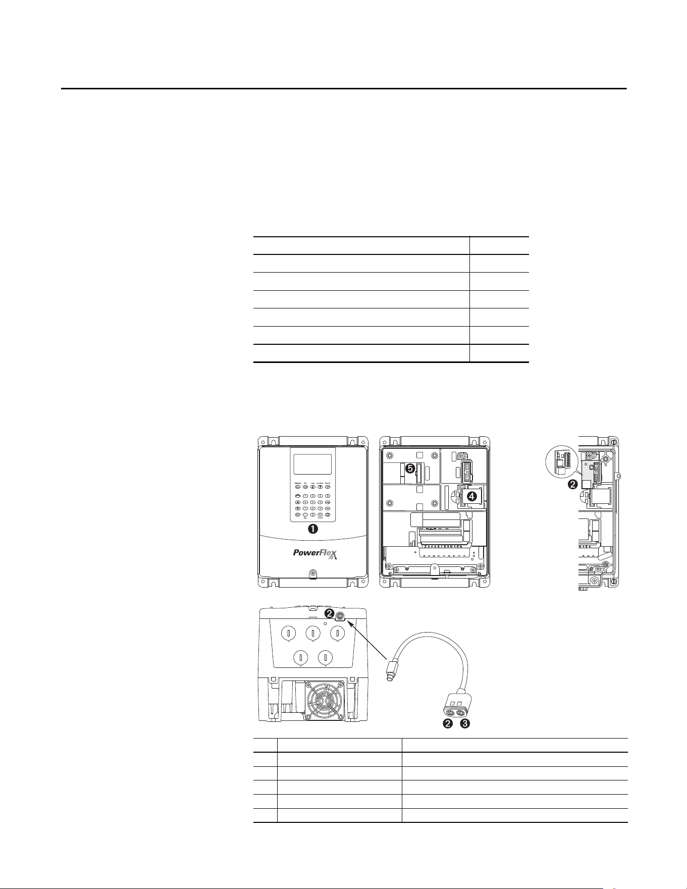
Rockwell Automation Publication 20A-UM001P-EN-P - February 2018 93
Appendix B
HIM Overview
This appendix provides information for connecting the HIM, and using the
HIM to view and program the drive parameters.
External and Internal
Connections
The PowerFlex 70 drive provides a number of cable connection points
(B frame shown).
Topic Page
External and Internal Connections 93
LCD Display Elements 95
ALT Functions 95
Removing the HIM 95
Menu Structure 96
Viewing and Editing Parameters 97
No. Connector Description
➊ DPI Port 1 HIM connection when installed in cover.
➋ DPI Port 2 Cable connection for handheld and remote options.
➌ DPI Port 3 Splitter cable that is connected to DPI Port 2 provides additional port.
➍ Control / Power Connection Connection between control and power boards.
➎ DPI Port 5 Cable connection for communications adapter.
CTRL BD
GND
2
1or3
COMM PORT
CTRL BD
GND
UIB CONN
CONTROL/POWER CONN
WIRE
STRIP
CONTROL
POWER
SK-M9-SCB1
IP 20
(NEMA/UL Type 1)
IP 66
(NEMA/UL Type 4X/12)
Optional Service
Connection Board
(SK-M9-SCB1)
provides temporary
DPI connection with
drive cover
removed.
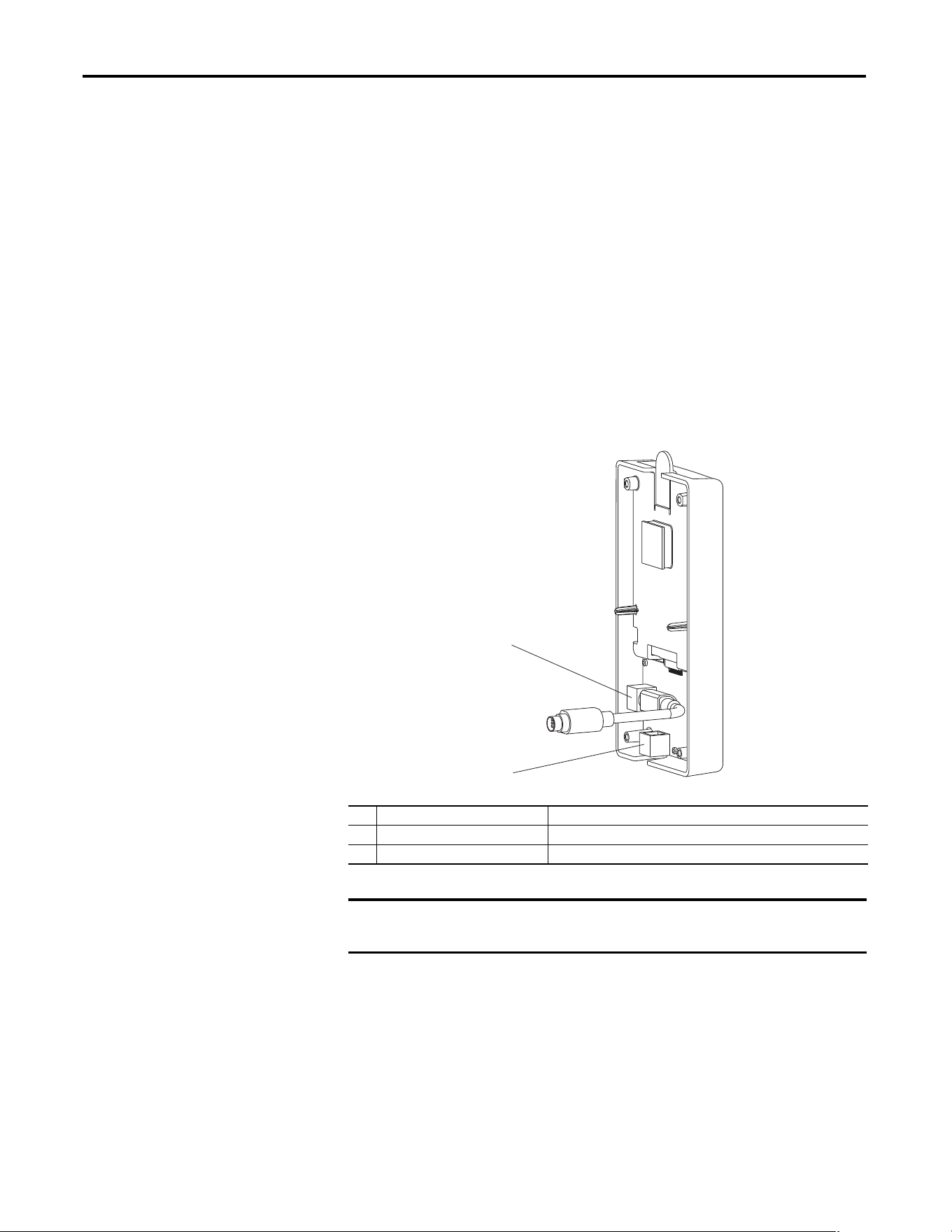
94 Rockwell Automation Publication 20A-UM001P-EN-P - February 2018
Appendix B HIM Overview
Using the HIM with a 20-HIM-B1 Bezel Kit
The 20-HIM-B1 bezel kit enables remote HIM or Wireless Interface Module
(WIM) operation and provides an additional remote DPI port for accessories.
Use the bezel cradle connection to mount the NEMA/UL 1 HIM or
NEMA/UL 1 WIM (port 3).
Use the accessory port on the bottom of the bezel for standard DPI peripherals
such as 1203-SSS, 1203-USB, or another handheld HIM (port 2, just like the
accessory port on the drive).
Use the internal connection on the back side of the bezel to connect the bezel to
the host drive with a standard DPI cable. The 20-HIM-B1 bezel kit cannot be
used with a 1203-S03 two-way splitter cable, or a 1203-SG2 two-way or
1203-SG4 four-way splitter module.
• If you are using the HIM in the bezel, set parameter 90 [Speed Ref A Sel]
or parameter 93 [Speed Ref B Sel] (depending on your application
requirements) to option 20 “DPI Port 3.”
• If you are using a remote 20-HIM-C* HIM connected directly into Port 2
on the bottom of the drive, set parameter 90 [Speed Ref A Sel] or
parameter 93 [Speed Ref B Sel] to option 19 “DPI Port 2.”
No. Connector Description
➊ Upper DPI port Connects the 20-HIM-B1 bezel to the drive.
➋ Lower DPI port Connects a 1203-SSS or 1203-USB converter to the drive.
IMPORTANT
The bezel’s lower DPI port is always port 2, and the cradle connection port is
always port 3.
➊
➋
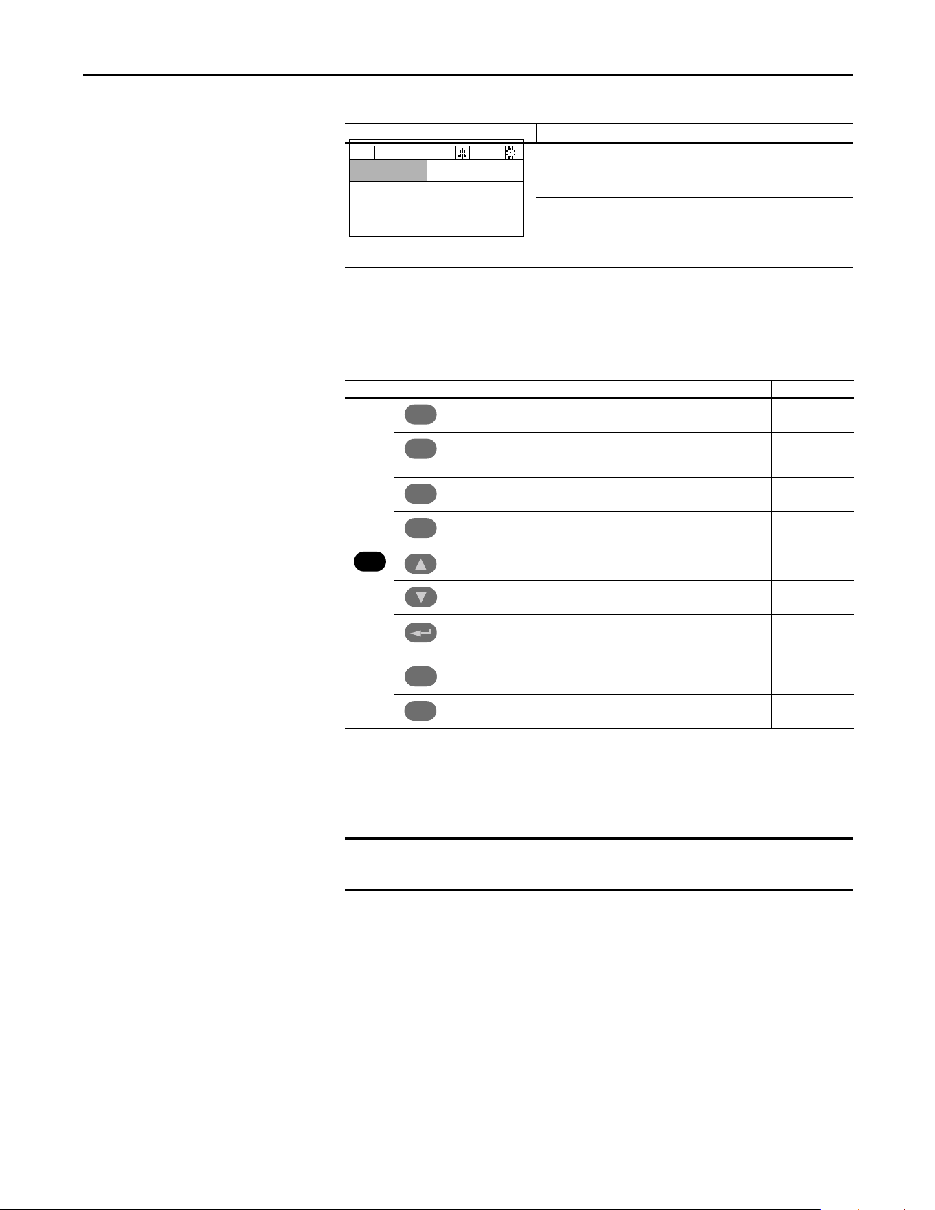
Rockwell Automation Publication 20A-UM001P-EN-P - February 2018 95
HIM Overview Appendix B
LCD Display Elements
ALT Functions
To use an ALT function, start at the Main Menu and press the ALT key, release it,
then press the programming key that is associated with one of the functions that
are listed in the table below.
Removing the HIM
The HIM can be removed while the drive is powered. Normally, the drive issues a
fault when the HIM is removed because it detects that a device is missing.
Display Description
Direction Drive Status Alarm Auto/Man Information
Commanded or Output Frequency
Programming / Monitoring / Troubleshooting
F-> Power Loss Auto
0.0
Hz
Main Menu:
Diagnostics
Parameter
Device Select
ALT Key and Then … Performs This Function … HIM Type
S.M.A.R.T. Displays the S.M.A.R.T. screen. LCD
Log In/Out Log in to change parameter settings.
Log out to protect parameter settings.
Change a password.
LED
View Enables the selection of how parameters are viewed, or
detailed information about a parameter or component.
LCD
Device Select a connected adapter for editing. LED
Lang Displays the language selection screen. LCD
Auto / Man Switches between Auto and Manual Modes. LCD and LED
Remove Enables HIM removal without causing a fault if the HIM is
not the last controlling device and does not have Manual
control of the drive.
LCD and LED
Exp Enables value to be entered as an exponent.
(Not available on PowerFlex 70.)
LCD
Param # Enables the entry of a parameter number for viewing/
editing.
LCD
ALT
Esc
Esc
Sel
Sel
.
.
+/–
IMPORTANT
HIM removal is permissible only in Auto mode. If the HIM is removed while in
Manual mode, or the HIM is the only remaining control device, a fault occurs.
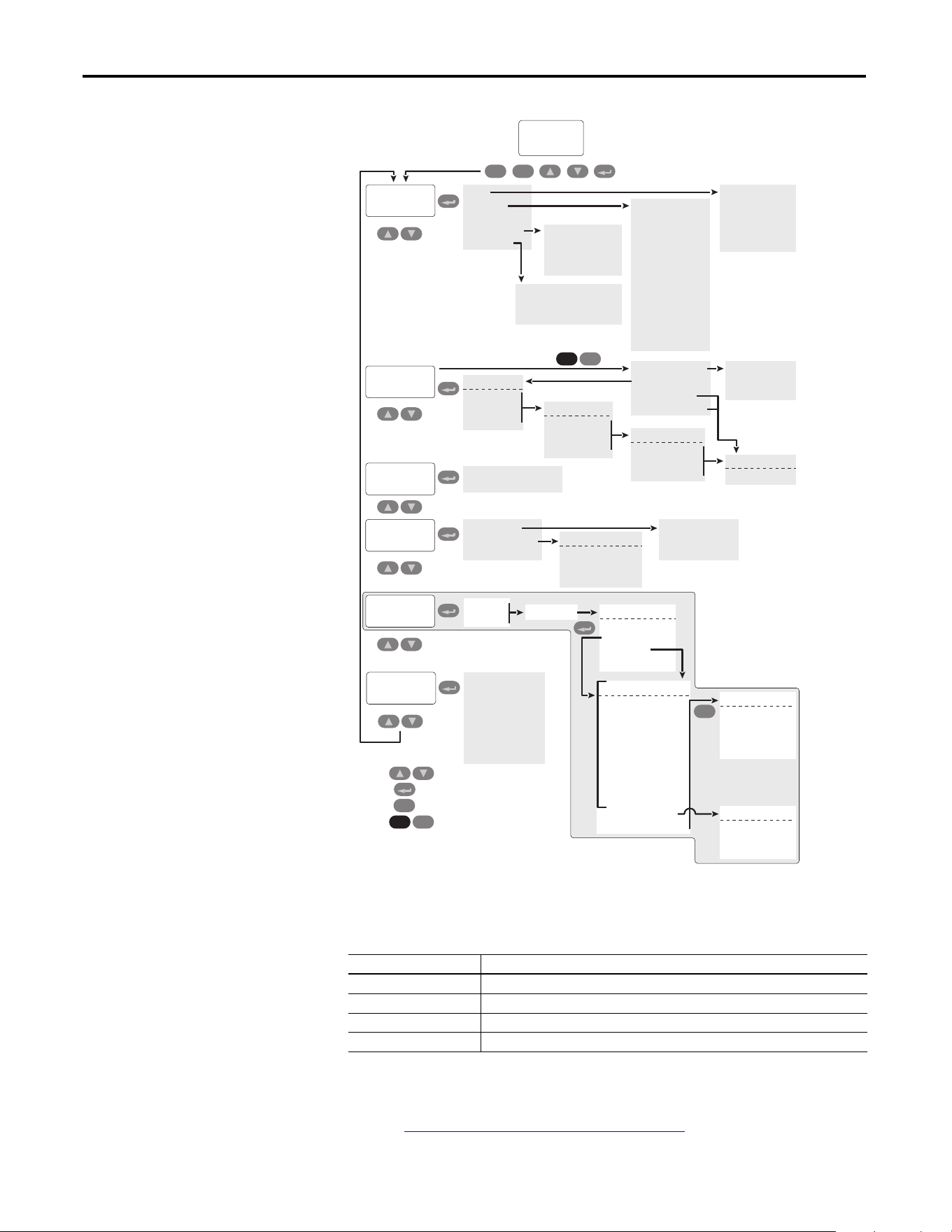
96 Rockwell Automation Publication 20A-UM001P-EN-P - February 2018
Appendix B HIM Overview
Menu Structure
Diagnostics Menu
When a fault trips the drive, use this menu to access detailed data about the drive.
Parameter Menu
Refer to Viewing and Editing Parameters on page 97.
Option Description
Faults View fault queue or fault information, clear faults, or reset drive.
Status Info View parameters that display status information about the drive.
Device Version View the firmware revision and hardware series of components.
HIM Version View the firmware revision and hardware series of the HIM.
User
Display
Diagnostics
Main Menu:
Start-Up
Esc Sel
Esc
Faults
Status Info
Device Items
Device Version
HIM Version
Fault Info
View Fault Queue
Clear Faults
Clr Fault Queue
Reset Device
Drive Status 1
Drive Status 2
Drive Alarm 1
Drive Alarm 2
Speed Ref Source
Start Inhibits
Last Stop Source
Dig In Status
Dig Out Status
Drive Temp
Drive OL Count
Motor OL Count
LCD Module Product Data
LCD HIM Control Board
Keyboard – Numeric
Continue
Start Over
Press
Press
Press
to move between menu items
Press to select how to view parameters
to select a menu item
to move 1 level back in menu
Memory Storage
HIM CopyCat
Device User Sets
Reset To Defaults
Device -> HIM
Device <- HIM
Delete HIM Set
Drive User Set:
Save To User Set
Load Frm Usr Set
Active Set Name
Introduction
PowerFlex 70 EC
Connected DPI Devices
Device Select
Parameter
Preferences
Device Identity
Change Password
User Dspy Lines
User Dspy Time
User Dspy Video
Reset User Dspy
Contrast
FGP: File
File 1 Name
File 2 Name
File 3 Name
FGP: Group
Group 1 Name
Group 2 Name
Group 3 Name
FGP: Parameter
Parameter Name
Parameter Name
Parameter Name
Basic
Advanced
Reserved
Param Access Lvl
File-Group-Par
Numbered List
Changed Params
ALT
Sel
ALT
Sel
Value Screen
PowerFlex 70 EC
Product Data
Main Control Board
Power Unit Board
Complete Steps:
1.
SC:
Input Voltage
EC:
Motor Control
2. Motor Dat/Ramp
3. Motor Tests
4. Speed Limits
5.
SC:
Speed Control
EC:
Speed/Freq
6. Strt/Stop/I/O
7.
SC:
Done/Exit
EC:
Application
8.
EC:
Done/Exit
(1)
Esc
Make a selection:
Abort
Backup
Resume
Start-Up Menu
Make a selection:
1. Flying Start
2. Auto Restart
3. Done
Make a selection:
1. SMART
2. Basic
3. Detailed
4. More Info
(1)
Important: Done/Exit must be selected upon completion of the Start-Up routine
in order for any Start Up/Autotune data to be saved.
View selected through
Rockwell Automation Publication 20A-UM001P-EN-P - February 2018 97
HIM Overview Appendix B
Device Select Menu
Use this menu to access parameters in connected peripheral devices.
Memory Storage Menu
• Drive data can be saved to, or recalled from, User and HIM sets.
•User sets are files that are stored in permanent nonvolatile drive memory.
•HIM sets are files that are stored in permanent nonvolatile HIM memory.
Preferences Menu
The HIM and drive have features that you can customize.
Viewing and Editing
Parameters
The PowerFlex 70 drive is initially set to the basic parameter view. Parameter 196
[Param Access Lvl] controls the parameter views that you can see. The list below
describes the different settings and view options for Parameter 196
[Param Access Lvl]:
•View basic parameters – To view the basic parameters, set parameter 196
[Param Access Lvl] to option 0 “Basic”.
•View all parameters – To view all parameters, set parameter 196 [Param
Access Lvl] to option 1 “Advanced”.
• View engineering parameters – To view engineering parameters, set
parameter 196 [Param Access Lvl] to option 2 “Reserved”.
Refer to the PowerFlex 70/700 Reference Manual, publication PFLEX-RM004
for descriptions of these parameters. Parameter 196 is not affected by the Reset to
Defaults function.
Option Description
HIM Copycat
Device -> HIM
Device <- HIM
Save data to a HIM set, load data from a HIM set to active drive memory, or delete a HIM set.
Device User Sets Save data to a user set, load data from a user set to active drive memory, or name a user set.
Reset To Defaults Restore the drive to its factory-default settings.
Option Description
Drive Identity Add text to identify the drive.
Change Password Enable/disable or modify the password.
User Dspy Lines Select the display, parameter, scale, and text for the user display. The user display is two lines
of user-defined data that appears when the HIM is not being used for programming.
User Dspy Time Set the wait time for the user display or enable/disable it.
User Dspy Video Select reverse or normal video for the frequency and user display lines.
Reset User Dspy Return all the options for the user display to factory default values.
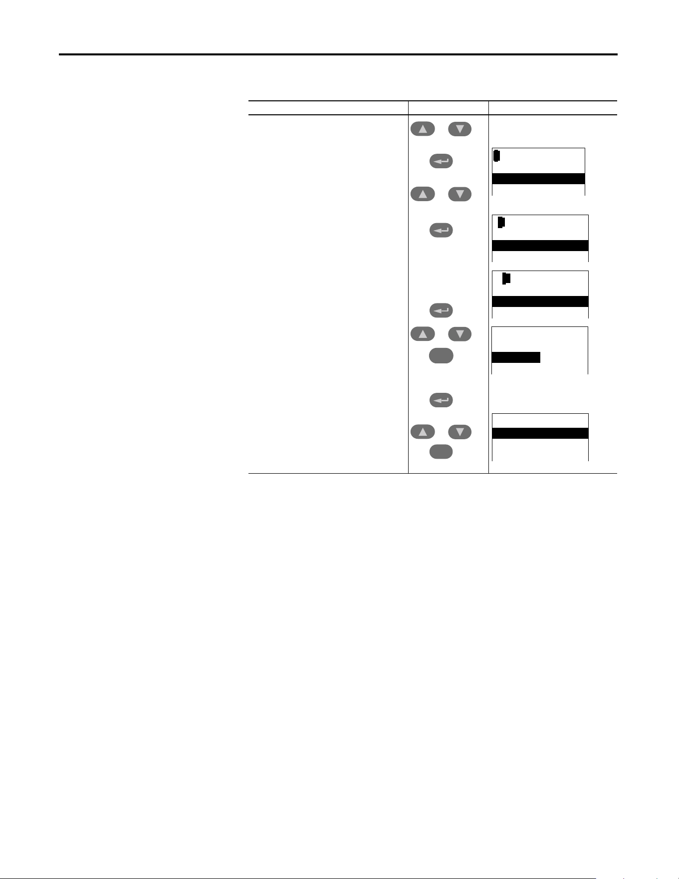
98 Rockwell Automation Publication 20A-UM001P-EN-P - February 2018
Appendix B HIM Overview
LCD HIM
Numeric Keypad Shortcut
If you are using a HIM with a numeric keypad, press the ALT key and the +/–
key to access the parameter by typing the parameter number.
Step Keys Example Displays
1. In the Main Menu, press the up arrow or down
arrow to scroll to “Parameter.”
2. Press Enter. “FGP File” appears on the top line
and the first three files appear below it.
3. Press the up arrow or down arrow to scroll
through the files.
4. Press Enter to select a file. The groups in the file
are displayed under it.
5. Repeat steps 3 and 4 to select a group and then
a parameter. The parameter value screen
appears.
6. Press Enter to edit the parameter.
7. Press the up arrow or down arrow to scroll
through the parameters. Press Sel to move the
courser down to change the value. If desired,
press Sel to move from digit to digit, letter to
letter, or bit to bit. The digit or bit that you can
change is highlighted.
8. Press Enter to save the value. If you want to
cancel a change, press Esc.
9. Press the up arrow or down arrow to scroll
through the parameters in the group, or press
Esc to return to the group list.
Sel
Esc
or
or
or
or
FGP: File
Monitor
Motor Control
Speed Command
FGP: Par 55
Maximum Freq
130.00 Hz
[ALT] [VIEW] -> Limits
FGP: Par 55
Maximum Freq
90.00 Hz
[ALT] [VIEW] -> Limits
FGP: Group
Motor Data
Torq Attributes
Volts per Hertz
FGP: Parameter
Maximum Voltage
Maximum Freq
Compensation

Rockwell Automation Publication 20A-UM001P-EN-P - February 2018 99
Appendix C
Application Notes
This appendix provides operational application notes.
Topic Page
External Brake Resistor 100
Skip Frequency 101
Stop Modes 103
Motor Overload 107
Motor Overload Memory Retention Per 2005 NEC 109
Start at Powerup 109
Overspeed 109
Speed Reference Control 110
Auto/Manual Examples 112
Process PI for Standard Control 113
Voltage Tolerance 115
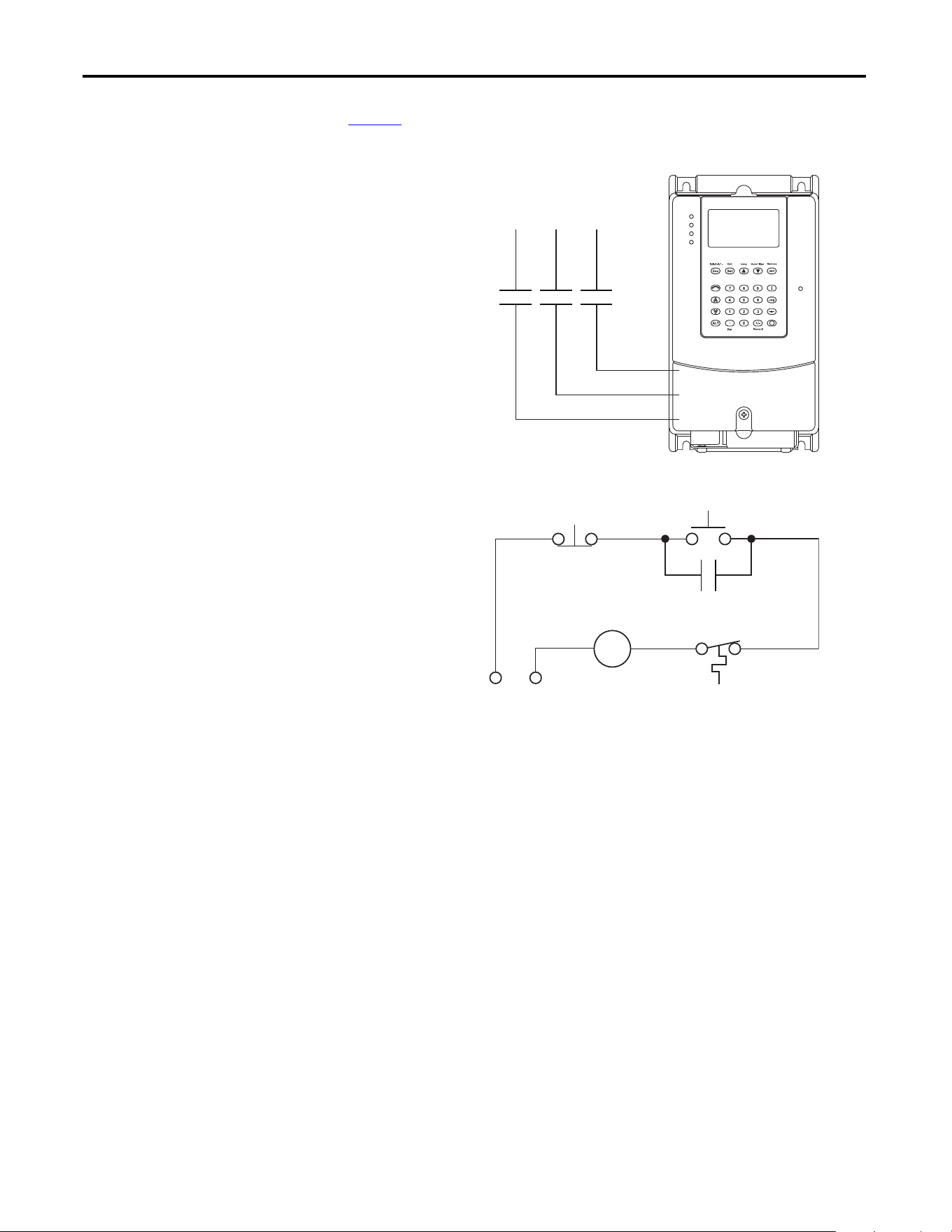
100 Rockwell Automation Publication 20A-UM001P-EN-P - February 2018
Appendix C Application Notes
External Brake Resistor
Figure 1 shows the external brake resistor circuitry.
Figure 1 - External Brake Resistor Circuitry
Power On
R (L1)
S (L2)
T (L3)
Power Source DB Resistor Thermostat
Power Off
M
M
(Input Contactor) M
Three-Phase
AC Input
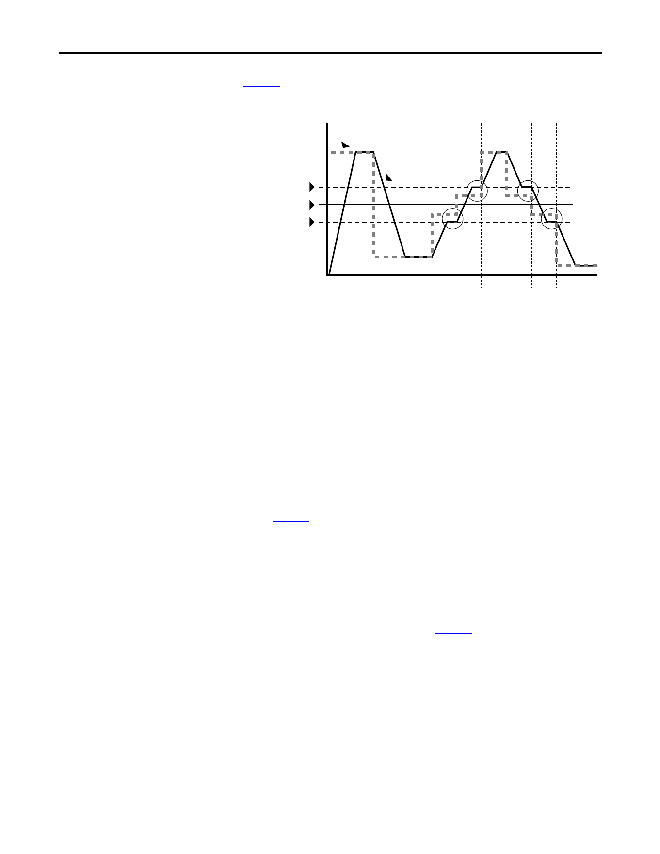
Rockwell Automation Publication 20A-UM001P-EN-P - February 2018 101
Application Notes Appendix C
Skip Frequency
Figure 2 shows the skip frequency band parameters.
Figure 2 - Skip Frequency
Some machinery can have a resonant operating frequency that must be avoided to
minimize the risk of equipment damage. To assure that the motor cannot
continuously operate at one or more of the points, skip frequencies are used.
parameters 084…086 ([Skip Frequency 1…3]) are available to set the frequencies
to be avoided.
The value that is programmed into the skip frequency parameters sets the center
point for an entire skip band of frequencies. The width of the band (range of
frequency around the center point) is determined by parameter 87, [Skip Freq
Band]. The range is split, half above and half below the skip frequency parameter.
If the commanded frequency of the drive is greater than or equal to the skip
(center) frequency and less than or equal to the high value of the band (skip plus
1/2 band), the drive sets the output frequency to the high value of the band. See
(A) in Figure 2
.
If the commanded frequency is less than the skip (center) frequency and greater
than or equal to the low value of the band (skip minus 1/2 band), the drive sets
the output frequency to the low value of the band. See (B) in Figure 2
.
Acceleration and deceleration are not affected by the skip frequencies. Normal
accel/decel proceeds through the band once the commanded frequency is greater
than the skip frequency. See (A) and (B) in Figure 2
. This function affects only
continuous operation within the band.
Frequency
Time
(A)
(A)
(B)
(B)
Skip Frequency
Command
Frequency
Drive Output
Frequency
Skip + 1/2 Band
Skip – 1/2 Band
35 Hz
30 Hz
25 Hz
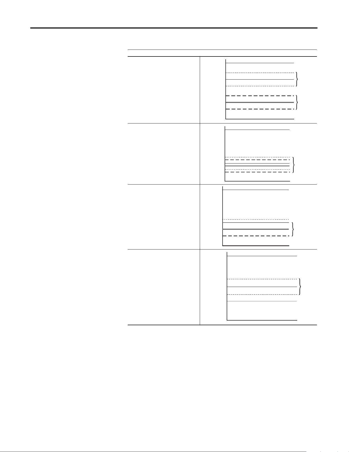
102 Rockwell Automation Publication 20A-UM001P-EN-P - February 2018
Appendix C Application Notes
Table 15 - Skip Frequency Examples
Skip Frequency Examples
The skip frequency has hysteresis so the
output does not toggle between high and
low values. Three distinct bands can be
programmed. If none of the skip bands
touch or overlap, each band has its own
high/low limit.
If skip bands overlap or touch, the center
frequency is recalculated based on the
highest and lowest band values.
If a skip band(s) extend beyond the max
frequency limits, the highest band value is
clamped at the max frequency limit. The
center frequency is recalculated based on
the highest and lowest band values.
If the band is outside the limits, the skip
band is inactive.
0 Hz
Skip Frequency 2
Skip Frequency 1
Max. Frequency
Skip Band 1
Skip Band 2
0 Hz
Skip Frequency 2
Skip Frequency 1
400 Hz.
Adjusted
Skip Band
w/Recalculated
Skip Frequency
0 Hz
Max.Frequency
Skip
400 Hz.
Adjusted
Skip Band
w/Recalculated
Skip Frequency
0 Hz
60 Hz. Max.
Frequency
Skip Frequency 1
400 Hz.
Inactive
Skip Band

Rockwell Automation Publication 20A-UM001P-EN-P - February 2018 103
Application Notes Appendix C
Stop Modes
Several methods are available for braking or stopping a load as described in the
table below.
In addition to these modes, the drive can be programmed for “Coast” and “Ramp
to Hold,” and are described in further detail in Detailed Operation
on page 105.
Method Use When Application Requires . . . Braking Power
Ramp • The fastest stopping time or fastest ramp time for speed changes (external
brake resistor or regenerative capability that is required for ramp times faster
than the methods below).
• High duty cycles, frequent stops, or speed changes. (The other methods can
result in excessive motor heating).
Most, if an
external resistor
or regenerative
device is
connected.
Fast brake • Additional braking capability without the use of an external brake resistor or
regenerative unit. Fast brake is effective during stop events, but not during
speed changes.
Important: For this feature to function properly the active Bus Reg Mode A or
B must be set to Adjust “Freq” and not be “Disabled”.
More than flux
braking or DC
brake.
Flux braking In some applications, Flux Braking can provide a method for fast speed changes or
stops. It is not suitable for high inertia loads or high duty cycle operation for
applications greater than 1 cycle per minute. This feature supplies additional flux
current to the motor and can cause motor thermistor or overvoltage faults in the
drive.
• Fast speed changes and fast stopping time.
• Typical stop from speeds below 50% of base speed (“Flux Braking” typically
stops the load faster than “Fast Brake” in this case).
Important: This can be used in conjunction with “Ramp” or “Ramp to Hold”
for additional braking power or with “Fast Brake” or “DC Brake” for speed
changes.
Important: For this feature to function properly the active Bus Reg Mode A or
B must be set to Adjust “Freq” and not be “Disabled”.
More than DC
brake.
DC brake • Additional braking capability without use of external brake resistor or
regenerative units.
Less than the
methods above.

104 Rockwell Automation Publication 20A-UM001P-EN-P - February 2018
Appendix C Application Notes
Configuration
• [Stop/Brk Mode A], parameter 155
• [Stop/Brk Mode B], parameter 156
– 0 = Coast
– 1 = Ramp
– 2 = Ramp to Hold
– 3 = DC Brake
– 4 = Fast Brake
• [DC Brk Lvl Sel], parameter 157
– 0 = “DC Brake Lvl” – selects parameter 158 as the source for the DC
brake level
– 1 = “Analog in 1”
– 2 = “Analog in 2”
• [DC Brake Level], parameter 158 – sets the DC brake level in amps, when
parameter 157 = “DC Brake Lvl”
• [DC Brake Time], parameter 159 – sets the amount of time that DC
braking is applied after the ramp (if any).
• [Flux Braking], parameter 166 – may need to adjust parameter 549
– 0 = Disabled
– 1 = Enabled
• [Digital InX Sel], parameters 361…366
– 13 = “Stop Mode B” – setting a digital input to this function enables
the use of a digital input to switch between Stop Mode A (open input)
and Stop Mode B (closed input).
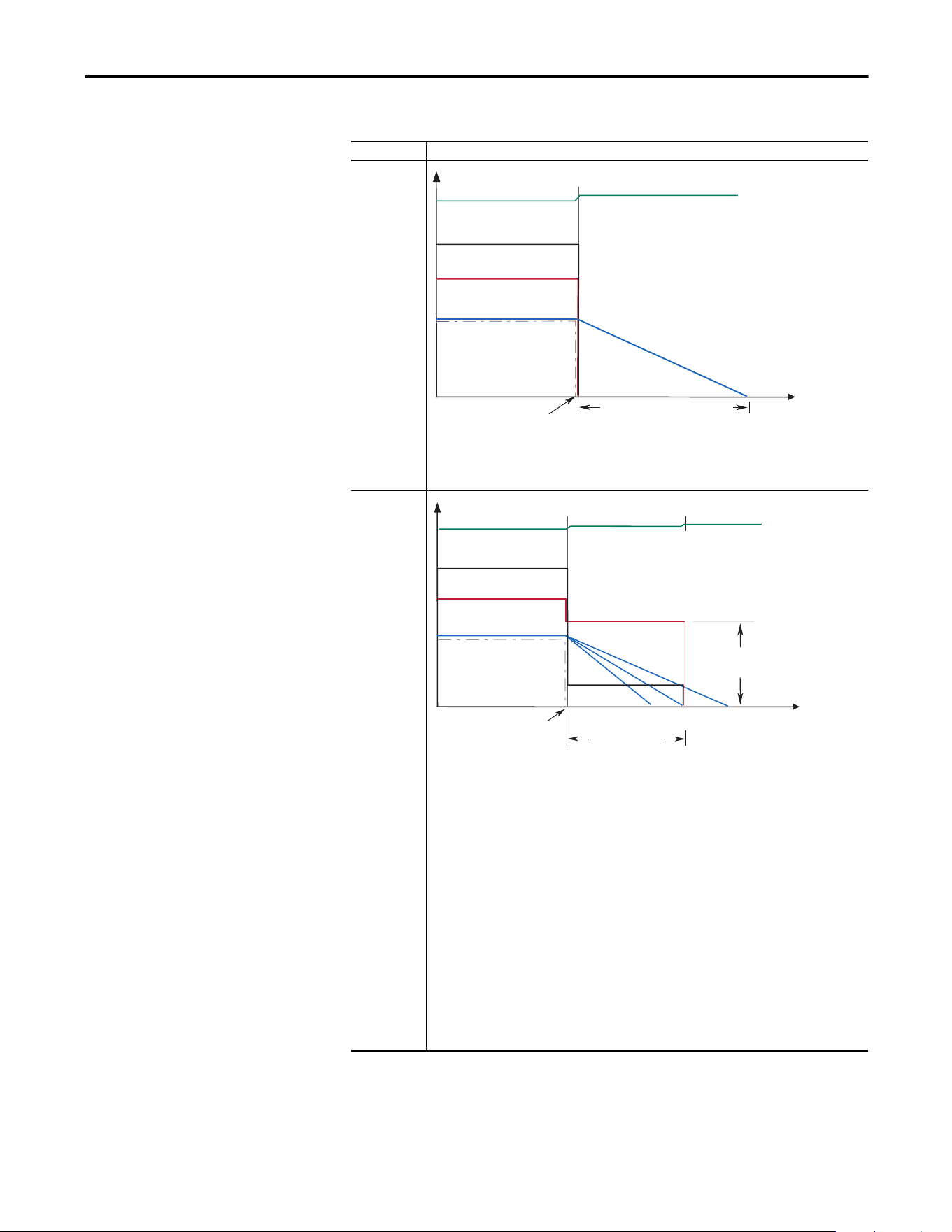
Rockwell Automation Publication 20A-UM001P-EN-P - February 2018 105
Application Notes Appendix C
Detailed Operation
Mode Description
Coast to Stop
Coast is selected by setting [Stop Mode A/B] to a value of “0.” When in Coast to Stop, the drive
acknowledges the Stop command by shutting off the drive output and releasing control of the motor.
The load and motor coasts until the kinetic energy is dissipated.
DC Brake to
Stop
This method uses DC injection of the motor to Stop and/or hold the load. DC Brake is selected by
setting [Stop Mode A/B] to a value of “3.” The amount of time that braking is applied is programmed in
[DC Brake Time] and the magnitude of the current used for braking is programmed in and [DC Brake
Level]. This mode of braking generates up to 40% of rated motor torque for braking and is typically
used for low inertia loads with infrequent Stop cycles.
1. On Stop, 3-phase drive output goes to zero (off)
2. Drive outputs DC voltage on the last used phase at the level that is programmed in [DC Brake Level],
parameter 158. This voltage causes a “stopping” brake torque. If the voltage is applied for a time
that is longer than the actual possible stopping time, the remaining time is used to attempt to hold
the motor at zero speed (decel profile “B” on the diagram above).
3. DC voltage to the motor continues for the amount of time that is programmed in [DC Brake Time],
parameter 159. Braking ceases after this time expires.
4. After the DC Braking ceases, no further power is supplied to the motor. The motor/load may or may
not be stopped. The drive has released control of the motor/load (decel profile “A” on the diagram
above).
5. The motor, if rotating, coasts from its present speed for a time that is dependent on the remaining
kinetic energy and the mechanics of the system (inertia, friction, and so on).
6. Excess motor current and/or applied duration, could cause motor damage. The user is also
cautioned that motor voltage can exist long after the Stop command is issued. The right
combination of Brake Level and Brake Time must be determined to provide the safest, most
efficient stop (decel profile “C” on the diagram above).
Coast Time is load dependent
Stop
Command
Time
Output Voltage
Bus Voltage
Output Current
Motor Speed
Command Speed
Stop
Command
DC Brake Time
(A)(C)(B)
Time
Output Voltage
Output Current
Motor Speed
DC
Brake Level
Bus Voltage
Command Speed
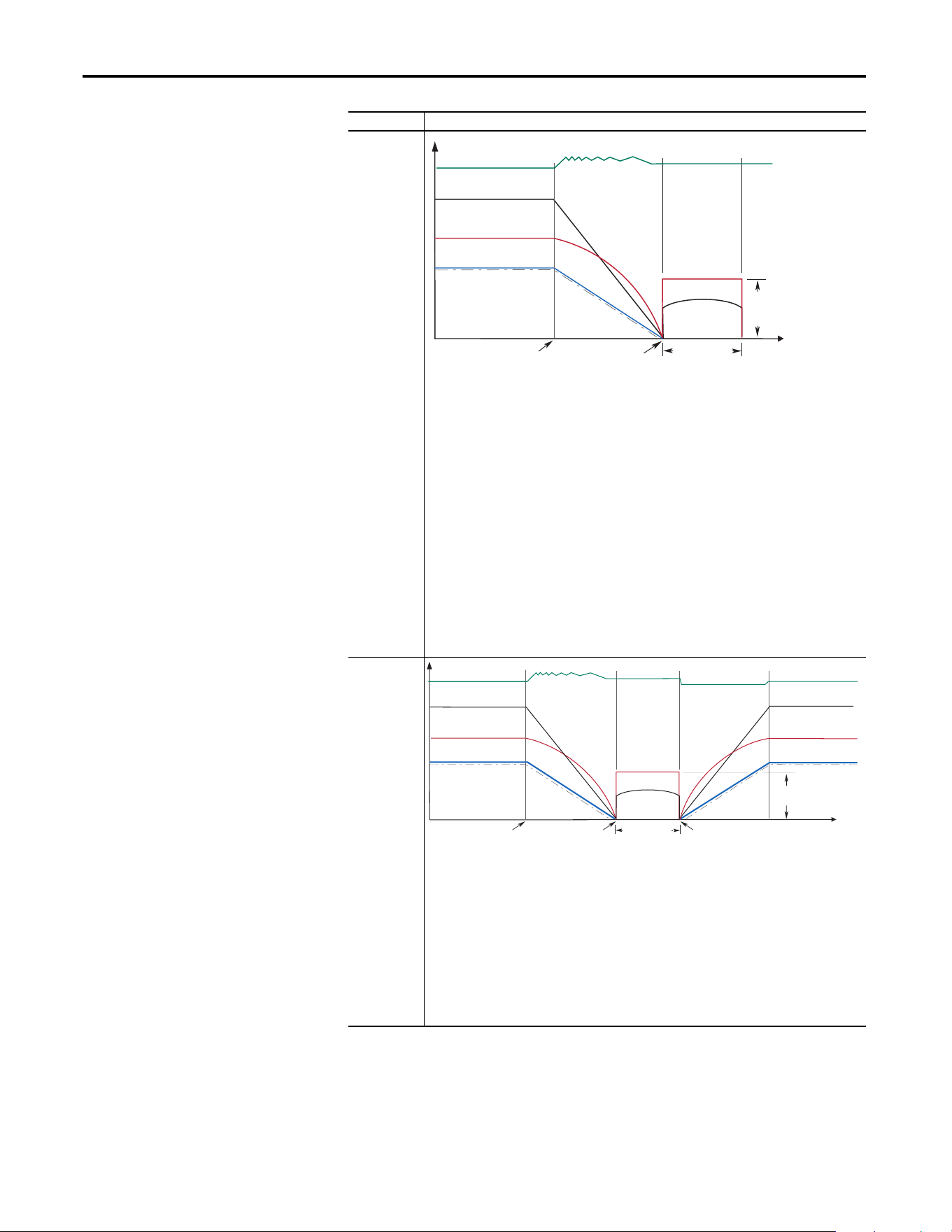
106 Rockwell Automation Publication 20A-UM001P-EN-P - February 2018
Appendix C Application Notes
Ramp
This method uses drive output reduction to stop the load. Ramp is selected by setting [Stop Mode A/B]
to a value of “1”. The drive ramps the frequency to zero based on the deceleration time that is
programmed into [Decel Time 1/2]. The “normal” mode of machine operation can utilize [Decel Time
1]. If the machine “stop” requires a faster deceleration than desired for normal deceleration, [Decel
Time 2] can be activated with a faster rate selected. When in Ramp mode, the drive acknowledges the
stop command by decreasing or “ramping” the output voltage and frequency to zero in a programmed
period (Decel Time), maintaining control of the motor until the drive output reaches zero. The drive
output is then shut off. The load and motor follow the decel ramp. Other factors such as bus regulation
and current limit can alter the actual decal rate.
Ramp mode can also include a “timed” hold brake. Once the drive has reached zero output hertz on a
Ramp-to-Stop and both parameters [DC Brake Time] and [DC Brake Level] are not zero, the drive
applies DC to the motor producing current at the DC Brake Level for the DC Brake Time.
1. On Stop, drive output decreases according to the programmed pattern from its present value to
zero. The pattern can be linear or squared. The output decreases to zero at the rate that is
determined by the programmed [Maximum Freq] and the programmed active [Decel Time x].
2. The reduction in output can be limited by other drive factors such as bus or current regulation.
3. When the output reaches zero, the output is shut off.
4. The motor, if rotating, coasts from its present speed for a time that is dependent on the mechanics
of the system (inertia, friction, and so on).
Ramp to Hold
This method combines two of the methods above. It uses drive output reduction to stop the load and
DC injection to hold the load at zero speed once it has stopped.
1. On Stop, drive output decreases according to the programmed pattern from its present value to
zero. The pattern can be linear or squared. The output decreases to zero at the rate that is
determined by the programmed [Maximum Freq] and the programmed active [Decel Time x].
2. The reduction in output can be limited by other drive factors such as bus or current regulation.
3. When the output reaches zero, 3-phase drive output goes to zero (off) and the drive outputs DC
voltage on the last used phase at the level that is programmed in [DC Brake Level], parameter 158.
This voltage causes a “holding” brake torque.
4. DC voltage to the motor continues until a Start command is reissued or the drive is disabled.
5. If a Start command is reissued, DC Braking ceases and the drive returns to normal AC operation. If an
Enable command is removed, the drive enters a “not ready” state until the enable is restored.
Mode Description
DC Brake Time
DC
Brake
Level
Stop
Command
Time
Output Voltage
Output Current
Motor Speed
Output Voltage
Output Current
Zero Command
Speed
Bus Voltage
Command Speed
DC
Brake Level
Time
Output Voltage
Output Voltage
Output Current
Output Current
Motor Speed
Output Voltage
Output Current
Motor Speed
Re-issuing a
Start Command
Stop
Command
Zero Command
Speed
Bus Voltage Bus Voltage
Command Speed Command Speed
DC Brake Time
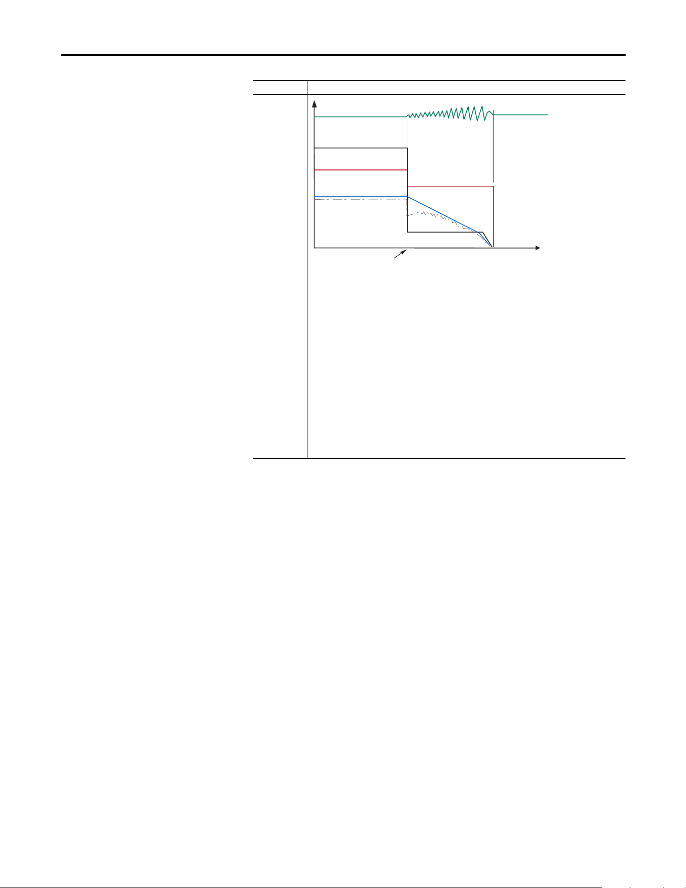
Rockwell Automation Publication 20A-UM001P-EN-P - February 2018 107
Application Notes Appendix C
Motor Overload
For single motor applications, the drive can be programmed to protect the motor
from overload conditions. An electronic thermal overload I
2
T function emulates
a thermal overload relay. This operation is based on these three parameters:
• 042 [Motor NP FLA]
• 047 [Motor OL Hertz]
• 048 [Motor OL Factor]
[Motor NP FLA] is multiplied by [Motor OL Factor] to let you define the
continuous level of current allowed by the motor thermal overload.
[Motor OL Hertz] is used to adjust the frequency below where the motor
overload is derated.
The motor can operate up to 102% of FLA continuously. If the drive was recently
activated, it runs at 150% of FLA for 180 seconds. If the motor had been
operating at 100% for over 30 minutes, the drive runs at 150% of FLA for 60
seconds. These values assume that the drive is operating above [Motor OL
Hertz], and that [Motor OL Factor] is set to 1.00.
Fast Brake
This method takes advantage of the characteristic of the induction motor whereby frequencies greater
than zero (DC braking) can be applied to a spinning motor that provides more braking torque without
causing the drive to regenerate.
1. On Stop, the drive output decreases based on the motor speed, keeping the motor out of the regen
region. This is accomplished by lowering the output frequency below the motor speed where
regeneration does not occur. This causes excess energy to be lost in the motor.
2. The method uses a PI based bus regulator to regulate the bus voltage to a reference (for example
750V) by automatically decreasing output frequency at the proper rate.
3. When the frequency is decreased to a point where the motor no longer causes the bus voltage to
increase, the frequency is forced to zero. DC brake is used to complete the stop if the DC Braking
Time is non-zero, then the output is shut off.
4. Use of the current regulator ensures that over current trips don’t occur and enable an easily
adjustable and controllable level of braking torque.
5. Use of the bus voltage regulator results in a smooth, continuous control of the frequency and forces
the maximum allowable braking torque to be utilized at all times.
6. Important: For this feature to function properly the active Bus Reg Mode A or B must be set to
Adjust “Freq” and NOT be “Disabled”.
Mode Description
Stop
Command
Time
Output Voltage
Output Current
Motor Speed
Bus Voltage
Command Speed
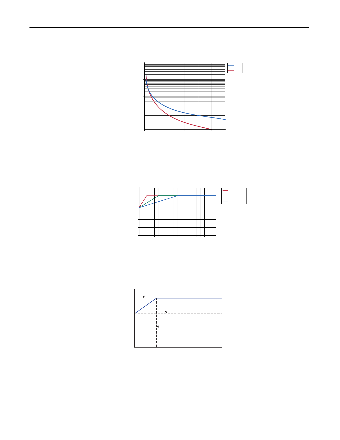
108 Rockwell Automation Publication 20A-UM001P-EN-P - February 2018
Appendix C Application Notes
Operation below 100% current causes the temperature calculation to account for
motor cooling.
[Motor OL Hertz] defines the frequency where motor overload capacity derate
begins. The motor overload capacity is reduced when operating below [Motor
OL Hertz]. For all settings of [Motor OL Hertz] other than zero, the overload
capacity is reduced to 70% at an output frequency of zero.
[Motor NP FLA] is multiplied by [Motor OL Factor] to select the rated current
for the motor thermal overload. This can be used to raise or lower the level of
current that causes the motor thermal overload to trip. The effective overload
factor is a combination of [Motor OL Hertz] and [Motor OL Factor].
The motor overload, if enabled, enables continuous operation at or below the
line. Above the line, the overload trips after a time delay. The further above the
line, the shorter the trip time.
Motor Overload Curve
100 125 150 175 200 225 250
Full Load Amps (%)
Trip Time (Sec)
Cold
Hot
10
100
1000
10000
100000
Changing Overload Hz
0102030405060708090100
% of Base Speed
Continuous Rating
OL Hz = 10
OL Hz = 25
OL Hz = 50
0
20
40
60
80
100
120
Trip Amps = P42 [Motor NP FLA] x P48 [Motor OL Factor]
P1 [Output Freq] (Hz)
P3 [Output Current] (Amps)
0.7 x Trip Amps
P47 [Motor OL Hertz]
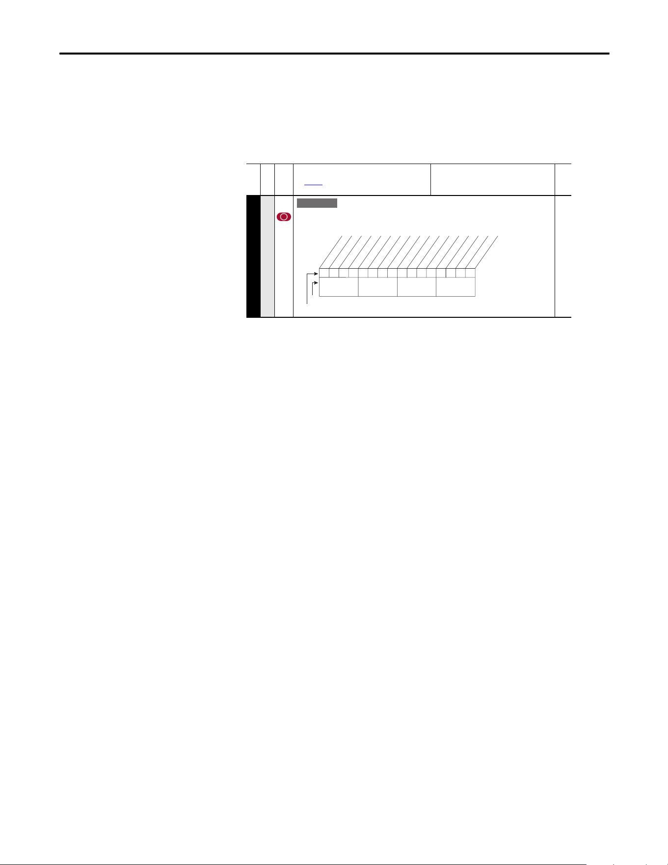
Rockwell Automation Publication 20A-UM001P-EN-P - February 2018 109
Application Notes Appendix C
Motor Overload Memory
Retention Per 2005 NEC
The PowerFlex 70 EC (firmware revision 3.002 or later) has the ability to retain
the motor overload count at power down per the 2005 NEC motor overtemp
requirement. A parameter has been added to provide this functionality. To
enable/disable this feature, refer to the information below.
Start at Powerup
When Start At Powerup in 2-wire control is configured, the drive starts if all start
permissive conditions are met (within 10 seconds of drive power being applied),
and the terminal block start input (Run, Run Forward or Run Reverse for 2-wire)
is closed. An alarm is annunciated from application of power until the drive
actually starts, indicating the powerup start attempt is in progress.
The powerup start attempt is aborted if any of the following occurs anytime
during the 10-second start interval:
• A fault condition occurs
• A Type 2 alarm condition occurs
• The terminal block programmed enable input is opened
• All terminal block run, run forward, or run reverse, inputs are canceled
• A Stop request (from any source) is received
If the drive has not started within the 10 second interval, the powerup start
attempt is terminated.
Overspeed
Overspeed Limit is a user programmable value that enables operation at
maximum speed, but also provides an overspeed band that enables a speed
regulator, such as encoder feedback or slip compensation, to increase the output
frequency above maximum speed to maintain maximum motor speed.
The figure below illustrates a typical custom V/Hz profile. Minimum speed is
entered in Hertz and determines the lower speed reference limit during normal
operation. Maximum speed is entered in Hertz and determines the upper speed
reference limit. The two speed parameters limit only the speed reference, not the
output frequency.
File B
Group
No.
Parameter Name and Description
See page 13 for Symbol Descriptions
Values
Related
MOTOR CONTROL (File B)
Motor Data
050 [Motor OL Mode]
If “0” [Motor OL Count], P220 is reset to zero by a drive reset or a power cycle. If “1” the
value is maintained. A “1” to “0” transition resets [Motor OL Count], P220 to zero.
E C v3
xxx 0xxxxxxxxxxxx
10 01234567891112131415
1 = Enabled
0 = Disabled
x = Reserved
Bit #
Factory Default Bit Values
Pwr Cyc Ret
Nibble 1Nibble 2Nibble 3Nibble 4
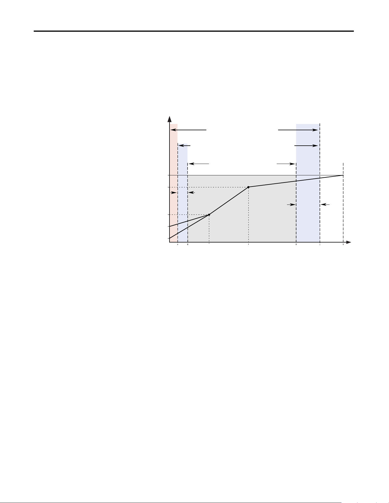
110 Rockwell Automation Publication 20A-UM001P-EN-P - February 2018
Appendix C Application Notes
The actual output frequency at maximum speed reference is the sum of the speed
reference plus speed adder components from functions such as slip
compensation.
The Overspeed Limit is entered in Hertz and added to Maximum Speed and the
sum of the two (Speed Limit) limit the output frequency. This sum (Speed
Limit) must be compared to Maximum Frequency and an alarm is initiated that
prevents operation if the Speed Limit exceeds Maximum Frequency.
Speed Reference Control
“Auto” Speed Sources
The drive speed command can be obtained from a number of different sources.
The source is determined by drive programming and the condition of the speed
select digital inputs, Auto/Manual digital input or reference select bits of a
command word.
The default source for a command reference (all speed select inputs open or not
programmed) is the selection that is programmed in P90 [Speed Ref A Sel]. If
any of the speed select inputs are closed, the drive uses other parameters as the
speed command source.
If a communication device is the source of the speed reference, refer to the
appropriate communications manual for additional information.
Frequency
Output Voltage
Note 1: The lower limit on this range can be 0 depending on the value of Speed Adder
Overspeed
Limit
Frequency Trim
due to Speed
Control Mode
Maximum
Voltage
Motor NP
Voltage
Run
Boost
Break
Voltage
Start
Boost
Allowable Output Frequency Range - Normal Operation
1
Allowable Speed Reference Range
Allowable Output Frequency Range -
Bus Regulation or Current Limit
Maximum
Frequency
Motor NP Hz0 Break
Frequency
Maximum
Speed
Minimum
Speed
Output
Frequency
Limit
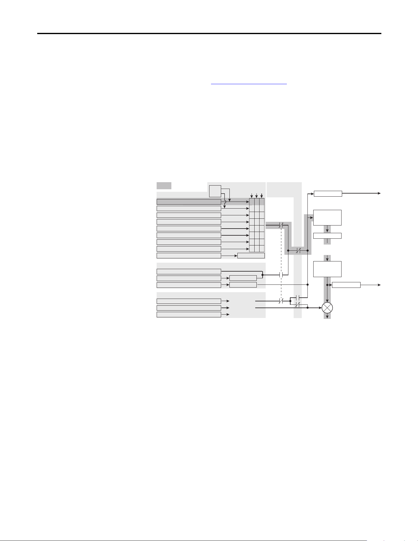
Rockwell Automation Publication 20A-UM001P-EN-P - February 2018 111
Application Notes Appendix C
“Manual” Speed Sources
The manual source for speed command to the drive is either the HIM requesting
manual control (see ALT Functions
on page 95) or the control terminal block
(analog input 1, 2, or MOP based on P96 [TB Man Ref Sel]) if a digital input is
programmed to “Auto/Manual”.
Changing Speed Sources
The selection of the active Speed Reference can be made through digital inputs,
DPI command, jog button, or Auto/Manual HIM operation.
Figure 3 - Speed Reference Selection Chart
(1)
(1) To access Preset Speed 1, set [Speed Ref A Sel] or [Speed Ref B Sel] to “Preset Speed 1”.
= Default
Speed Ref B Sel, Parameter 093
Preset Speed 2, Parameter 102
Preset Speed 3, Parameter 103
Preset Speed 4, Parameter 104
Preset Speed 5, Parameter 105
Preset Speed 6, Parameter 106
Preset Speed 7, Parameter 107
TB Man Ref Sel, Parameter 096
Digital Input
DPI Port Ref 1-6, See Parameter 209
DPI Command
Jog Speed, Parameter 100
Jog Command
HIM Requesting Auto/Manual
Trim
[Digital Inx Select]:
Speed Sel
321
001
011
010
100
101
110
11
1
Auto
Man
Drive Ref Rslt
Commanded
Frequency
Min/Max Speed
Acc/Dec Ramp
and
S Curve
Pure Reference
Post Ramp
to follower drive for
Frequency Reference
to follower drive for
Frequency Reference
Auto Speed Ref Options
Manual Speed Ref Options
Slip Compensation
1 "Slip Comp"
None
0 "Open Loop"
PI Output 2 "Process Pi"
Speed Adders [Speed Mode]:
PI Exclusive Mode
[PI Configuration]:
Bit 0, Excl Mode = 0
Output
Frequency
Mod Functions
(Skip, Clamp,
Direction, etc.)
Speed Ref A Sel, Parameter 090
000
Drive Ramp Rslt

112 Rockwell Automation Publication 20A-UM001P-EN-P - February 2018
Appendix C Application Notes
Auto/Manual Examples
PLC = Auto, HIM = Manual
A process is run by a PLC when in Auto mode and requires manual control from
the HIM during setup. The auto speed reference is issued by the PLC through a
communications module that is installed in the drive. Because the internal
communications is designated as port 5, P90 [Speed Ref A Sel] is set to “DPI
Port 5” with the drive running from the Auto source.
Attain Manual Control
• Press ALT then Auto/Man on the HIM.
When the HIM attains manual control, the drive speed command comes
from the HIM speed control keys.
Release to Auto Control
• Press ALT then Auto/Man on the HIM again.
When the HIM releases manual control, the drive speed command returns
to the PLC.
PLC = Auto, Terminal Block = Manual
A process is run by a PLC when in Auto mode and requires manual control from
an analog potentiometer that is wired to the drive terminal block. The auto speed
reference is issued by the PLC through a communications module that is installed
in the drive. Because the internal communications is designated as port 5, P90
[Speed Ref A Sel] is set to “DPI Port 5” with the drive running from the Auto
source. Because the Manual speed reference is issued by an analog input (“Analog
In 1 or 2”), P96 [TB Man Ref Sel] is set to the same input. To switch between
Auto and Manual, [Digital In4 Sel] is set to “Auto/ Manual”.
Attain Manual Control
• Close digital input 4.
With the input closed, the speed command comes from the potentiometer.
Release to Auto Control
• Open digital input 4.
With the input open, the speed command returns to the PLC.
Auto/Manual Notes
1. Manual control is exclusive. If a HIM or terminal block takes manual
control, no other device can take manual control until the controlling
device releases manual control.
2. If a HIM has manual control and power is removed from the drive, the
drive returns to Auto mode when power is reapplied.
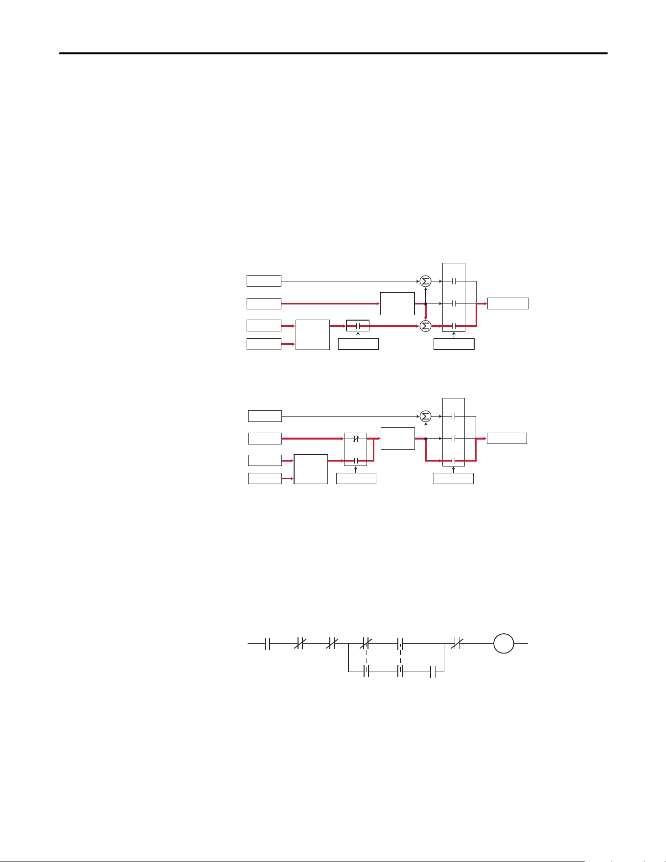
Rockwell Automation Publication 20A-UM001P-EN-P - February 2018 113
Application Notes Appendix C
Process PI for Standard
Control
The internal PI function of the PowerFlex 70 provides closed loop process
control with proportional and integral control action. The function is designed
for use in applications that require simple control of a process without external
control devices. The PI function enables the microprocessor of the drive to
follow a single process control loop.
The PI function reads a process variable input to the drive and compares it to a
desired setpoint stored in the drive. The algorithm then adjusts the output of the
PI regulator, changing drive output frequency to try and make the process
variable equal the setpoint.
It can operate as trim mode by summing the PI loop output with a master speed
reference.
Or, it can operate as control mode by supplying the entire speed reference. This
method is identified as Exclusive mode.
PI Enable
The output of the PI loop can be turned on (enabled) or turned off (disabled).
This control enables the user to determine when the PI loop is providing part or
all of the commanded speed. The logic for enabling the PI loop is shown in
below.
The drive must be running for the PI loop to be enabled. The loop is disabled
when the drive is ramping to a stop, jogging, or the signal loss protection for the
analog input or inputs is sensing a loss of signal.
+
Spd Cmd
Process PI
Controller
Linear Ramp
& S-Curve
+
+
+
PI Enabled
Speed Control
Spd Ref
PI Ref
PI Fbk
Slip Adder
Open
Loop
Slip
Comp
Process
PI
Spd Cmd
Process PI
Controller
Linear Ramp
& S-Curve
+
+
PI Enabled
Speed Control
Spd Ref
PI Ref
PI Fbk
Slip Adder
Open
Loop
Slip
Comp
Process
PI
Drive
Running
Drive
Ramping
to Stop
Drive
Jogging
Bit 0 of
[PI Control] = 1
(enabled) Signal Loss
The Configured
Digital Input
is Closed
A Digital Input
is Configured
to PI Enable
"Enabled" Status
Digital Input
is Reflected
in [PI Status]
Bit 0 = 1
The PI Loop
is Enabled
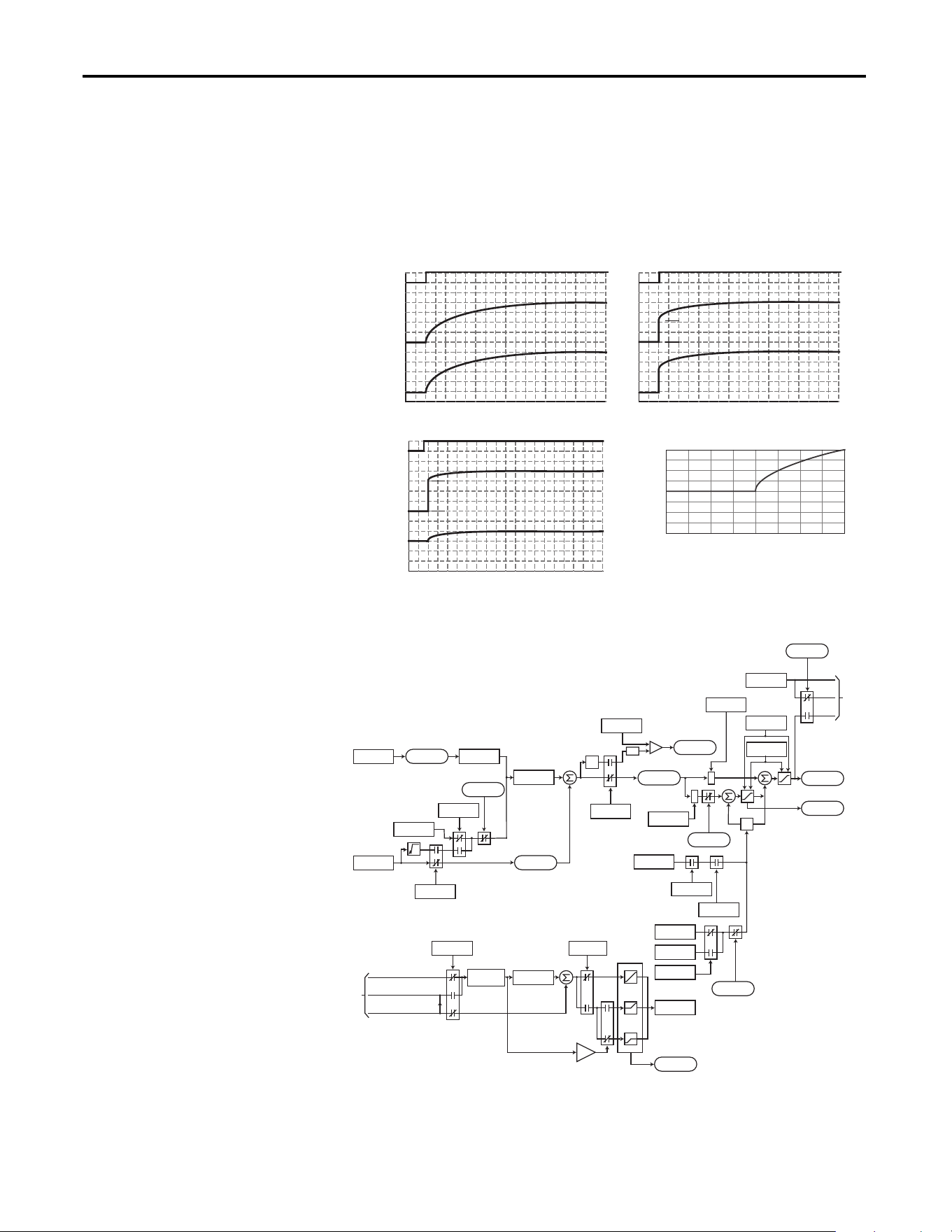
114 Rockwell Automation Publication 20A-UM001P-EN-P - February 2018
Appendix C Application Notes
If a digital input has been configured to “PI Enable,” two events are required to
enable the loop: the digital input must be closed AND bit 0 of the PI Control
parameter must be = 1.
If no digital input is configured to “PI Enable,” the Bit 0 = 1 condition must be
met. If the bit is permanently set to “1”, the loop is enabled as soon as the drive
goes into “run”.
PI Enabled
Spd Cmd
PI Output
PI Pre-load Value
PI Pre-load Value = 0 PI Pre-load Value > 0
Pre-load to Command Speed
PI Enabled
Spd Cmd
PI Output
Start at Spd Cmd
-100.0 -75.0 -50.0 -25.0 0.0 25.0 50.0 75.0 100.0
Normalized Feedback
Normalized SQRT(Feedback)
-100.0
-75.0
-50.0
-25.0
0.0
25.0
50.0
75.0
100.0
+
+
+
+
z
-1
*
*
PI Fbk
PI Error
PI Output
PI Ref
PI Cmd
Linear
Ramp
-
+
-
In Limit
PI XS Error
abs
PI_Config
.Exclusive
Current Limit
or Volt Limit
Spd Cmd
*(PI Ref Sel)
*(PI Fbk Sel)
PI Kp
Spd Ref
PI Ki
PI Neg Limit
PI Pos Limit
PI_Status
.Hold
PI_Config
.RampCmd
PI_Status
.Enabled
PI_Config
.Invert
PI_Config
.Sqrt
0
PI ExcessErr
PI_Config
.PreloadCmd
Preload Value
PI_Status
.Enabled
Spd Cmd
PI_Status
.Enabled
to
A
Linear Ramp
& S-Curve
Spd Ramp
0
+
+
Zclamped
PI_Config
.Exclusive
PI_Config
.ZeroClamp
+32K
0
-32K
0
+32K
-32K
Spd Cmd
A
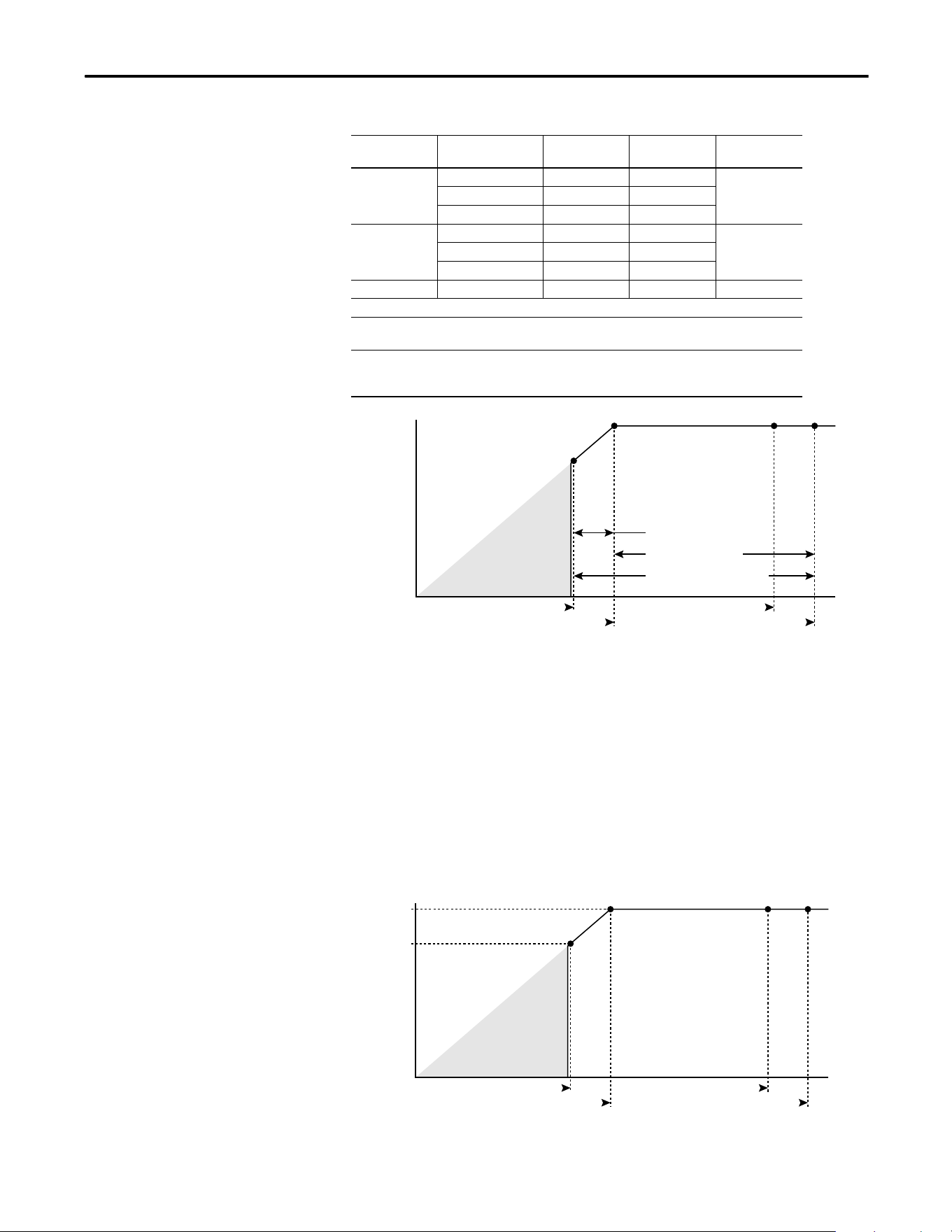
Rockwell Automation Publication 20A-UM001P-EN-P - February 2018 115
Application Notes Appendix C
Voltage Tolerance
This section describes voltage tolerances for the different drive ratings.
Example:
Calculate the maximum power of a 5 Hp, 460V motor connected to a 480V rated
drive supplied with 342V Actual Line Voltage input.
• Actual Line Voltage / Nominal Motor Voltage = 74.3%
• 74.3% 5 Hp = 3.7 Hp
• 74.3% 60 Hz = 44.6 Hz
At 342V Actual Line Voltage, the maximum power the 5 Hp, 460V motor can
produce is 3.7 Hp at 44.6 Hz.
Drive Rating Nominal Line
Voltage
Nominal Motor
Voltage
Drive Full Power
Range
Drive Operating
Range
200…40 200 200† 200…264 180…264
208 208 208…264
240 230 230…264
380…400 380 380† 380…528 342…528
400 400 400…528
480 460 460…528
500…600 600 575† 575…660 432…660
Drive full power range = Nominal motor voltage to drive rated voltage + 10%.
Rated current is available across the entire drive full power range
Drive operating range = Lowest nominal motor voltage - 10% to drive rated voltage + 10%.
Drive output is linearly derated when the actual line voltage is less than
the nominal motor voltage.
HP @ Motor (Drive Output)
Actual Line Voltage (Drive Input)
Full Power Range
Drive Operating Range
Nominal Motor Voltage -10%
Nominal Motor Voltage
Derated Power Range
No Drive
Output
Drive Rated Voltage
Drive Rated Voltage +10%
5 HP
3.7 HP
HP @ Motor (Drive Output)
Actual Line Voltage (Drive Input)
342V
460V
No Drive
Output
480V
528V

116 Rockwell Automation Publication 20A-UM001P-EN-P - February 2018
Appendix C Application Notes
Notes:

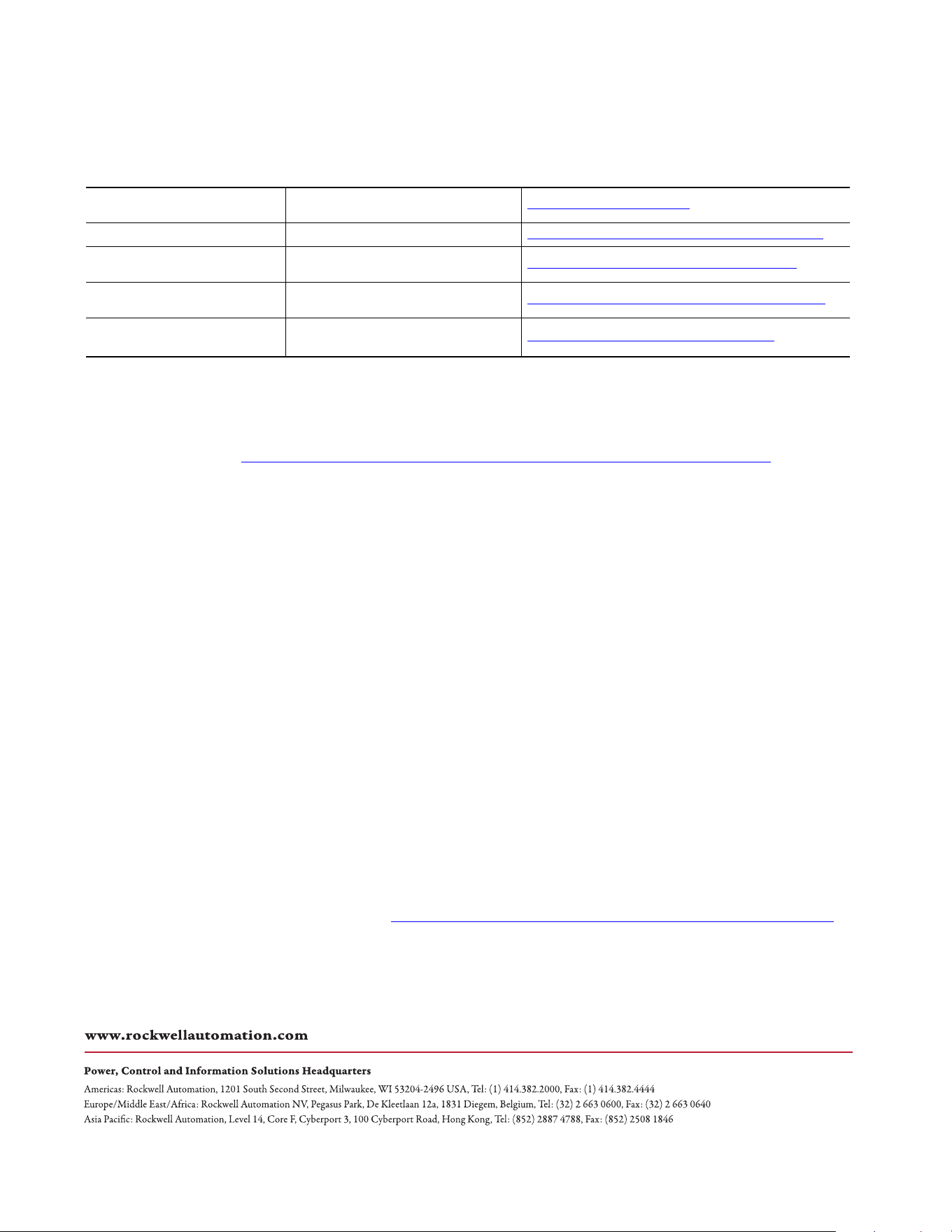
Publication 20A-UM001P-EN-P - February 2018 Copyright © 2018 Rockwell Automation, Inc. All rights reserved. Printed in the U.S.A.
Supersedes Publication 20A-UM001O-EN-P - July 2014
Rockwell Automation Support
Use the following resources to access support information.
Documentation Feedback
Your comments will help us serve your documentation needs better. If you have any suggestions on how to improve this document, complete the
HowAre We Doing? form at http://literature.rockwellautomation.com/idc/groups/literature/documents/du/ra-du002_-en-e.pdf
.
Technical Support Center
Knowledgebase Articles, How-to Videos, FAQs, Chat, User
Forums, and Product Notification Updates.
https://rockwellautomation.custhelp.com/
Local Technical Support Phone Numbers Locate the phone number for your country. http://www.rockwellautomation.com/global/support/get-support-now.page
Direct Dial Codes
Find the Direct Dial Code for your product. Use the code to
route your call directly to a technical support engineer.
http://www.rockwellautomation.com/global/support/direct-dial.page
Literature Library
Installation Instructions, Manuals, Brochures, and
Technical Data.
http://www.rockwellautomation.com/global/literature-library/overview.page
Product Compatibility and Download
Center (PCDC)
Get help determining how products interact, check
features and capabilities, and find associated firmware.
http://www.rockwellautomation.com/global/support/pcdc.page
.
Rockwell Otomasyon Ticaret A.Ş., Kar Plaza İş Merkezi E Blok Kat:6 34752 İçerenköy, İstanbul, Tel: +90 (216) 5698400
Rockwell Automation maintains current product environmental information on its website at http://www.rockwellautomation.com/rockwellautomation/about-us/sustainability-ethics/product-environmental-compliance.page.
Allen-Bradley, CompactLogix, Connected Components Workbench, ControlLogix, ControlFLASH, DPI, MicroLogix, PLC-5, PowerFlex, Rockwell Software, Rockwell Automation, RSLinx, RSLogix, RSLogix 5000, SLC, Stratix, Studio 5000,
Studio 5000 Logix Designer, and TotalFORCE are trademarks of Rockwell Automation, Inc. Trademarks not belonging to Rockwell Automation are property of their respective companies.