User Manual
TRIPLETT
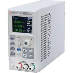
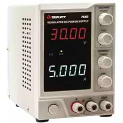
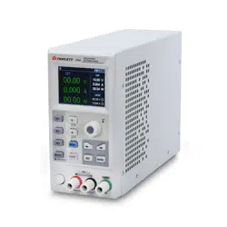
PS605 DC Power Supply (80V/5100
6 f
1
1
1
1
1
11
1
1
11
11
11
11
11
I
111
11
111
11
::
,,
1111
11
t
111
llllll
lt
11 1
1111111 II I
111111111 Ill
111111
11111
I
1111
111
11
II
1
111
111
111
II
.
U
III
I
I
I
II
1
11
1
1
11
I
I
:
I
I
I
I
I
I
II
II
I
I
11
1
1
t
l
l
l
I
t
i
1
1
11•••:,,
,1
1
I
I
t
i
I
I
I
I
I
I
I
1
1
1
I
:
I
I
I
I
'
I
I
I
I
t
i
I
ti
,,, ,
,
I
I
I
I
I
I
I
I
,
,
I
I
CE

3
Warning Caution:
To avoid possible electric shock and personal safety problem, please follow the instructions below.
Disclaimer
Please read the following safety information carefully beforestarting to use
the instrument. Uni-Trend will not be responsible for the personal safety
and property damage caused by the user's failure to comply with the
following terms.
Instrument Grounding
To prevent the risk of electric shock, please connect the power ground wire.
Operating voltage
Please make sure operating voltage under rated range of 10%, to avoid
damage the instrument.
Input voltage
Please use AC 110V~220V 50/60Hz AC power supply, use national approved
power cord and make sure insulating layer is in good condition.
Inspecting the wire of the
instrument
Inspecting the condtion of the insulating layer of the wire, check if it is
broken, bareness or workable. If the wire is damaged, please replace it
before connect with the instrument.
Fuse wire of the instrument
Only allowed use the dictated specification fuse wire.
Over-voltage protection
Please make sure the instrument is not over-voltage(such as the voltage
casused by thunder. To prevent operating personnel away from electric
shock.
4
Do Not
open the cover when the
instrument is inoperating
Please do not operating the instrument when open the cover and do not
change the internal circuit.
Do Not
touch live part
When the instrument is in operating, do not touch the bare connect wire,
spare input terminal and the circuit is in testing. When the instrument is
over DC 60V or AC 30V, be careful electric shock.
Do Not
use the instrument in an
explosive atmosphere
Do not use the instrument in flammable and explosive gas, steam or dusty
environment.
The use of any electronic equipment in such an environment is a risk to
personal safety.
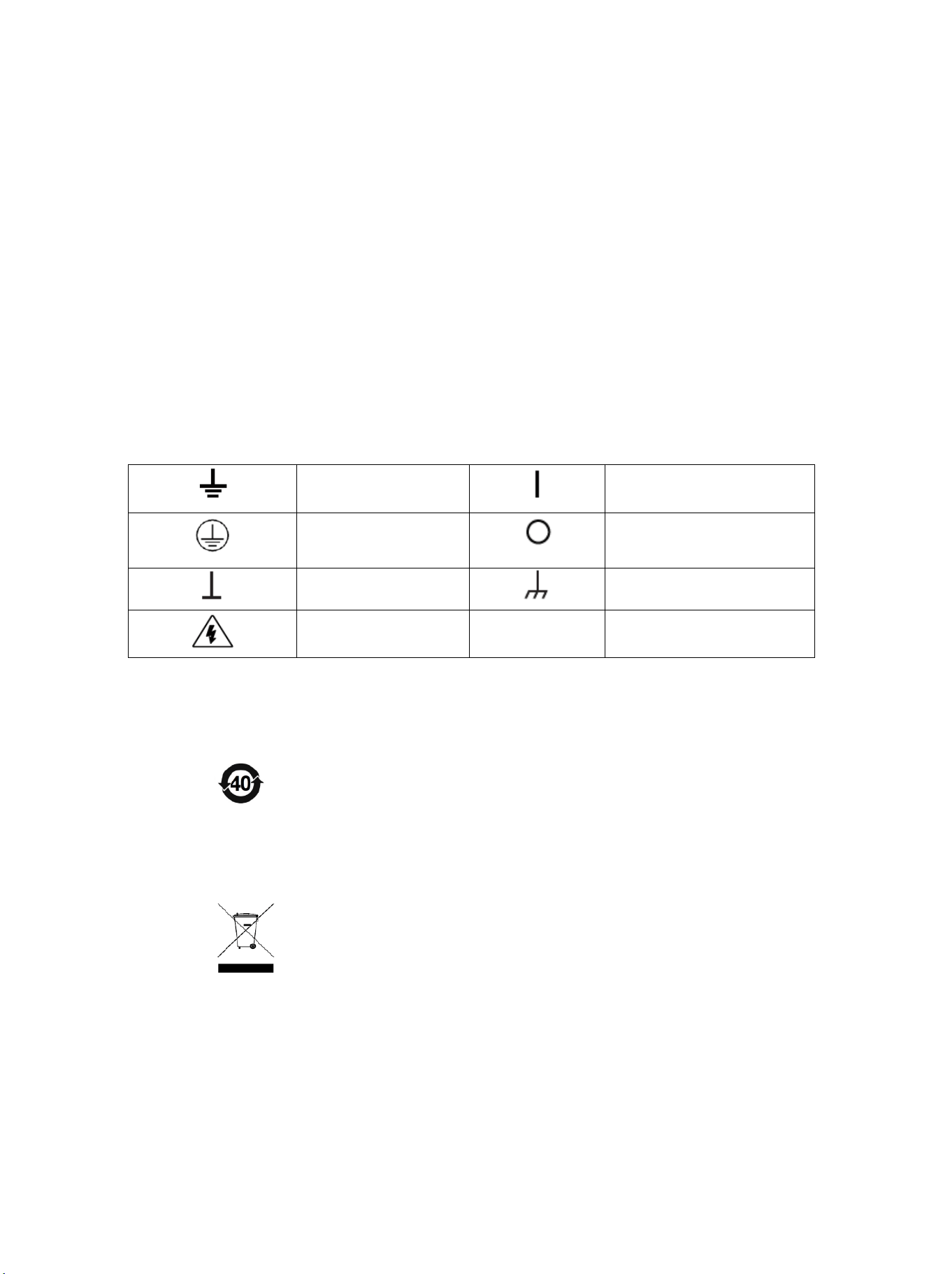
Safety Mark
Grounding
On (Power)
Protective Grounding
Off (Power)
Signal Ground
Connect with Cabinet or Case
Dangerous Mark
Environment-friendly Use Period
EFUP is the period of time before any of the RoHS substances are likely
to leak out, causing possible harm to health and the environment. EFUP
of this instrument is 40 years, it should be recycling system when
exceed 40 years.
Waste Electrical and Electronic Equipment (WEEE) Directive 2002/96/EC
Must not be discarded in the trash can.
5
Product Series
Model
Output Range
PS605
0-60V,0-5A, 0-100W
Characteristics
Fully digital control
High resolution 10mV/1mA in full range
Low ripple and noise
Software cailbration
Smallest outline
High-definition LCD display
Remote Sensecompensaton
Support RS-232 communication
Intelligent fan regulation
Rated voltage and current output·
High-reliability: OVP(over voltage protection)/OCP(over current protection)/OTP(over temperature protection)
Output on/off control
High performance-price ratio
Storage for 3x200 preset voltage and current output
Support List Mode(Time Function) and Delayer Mode
Basic Performance
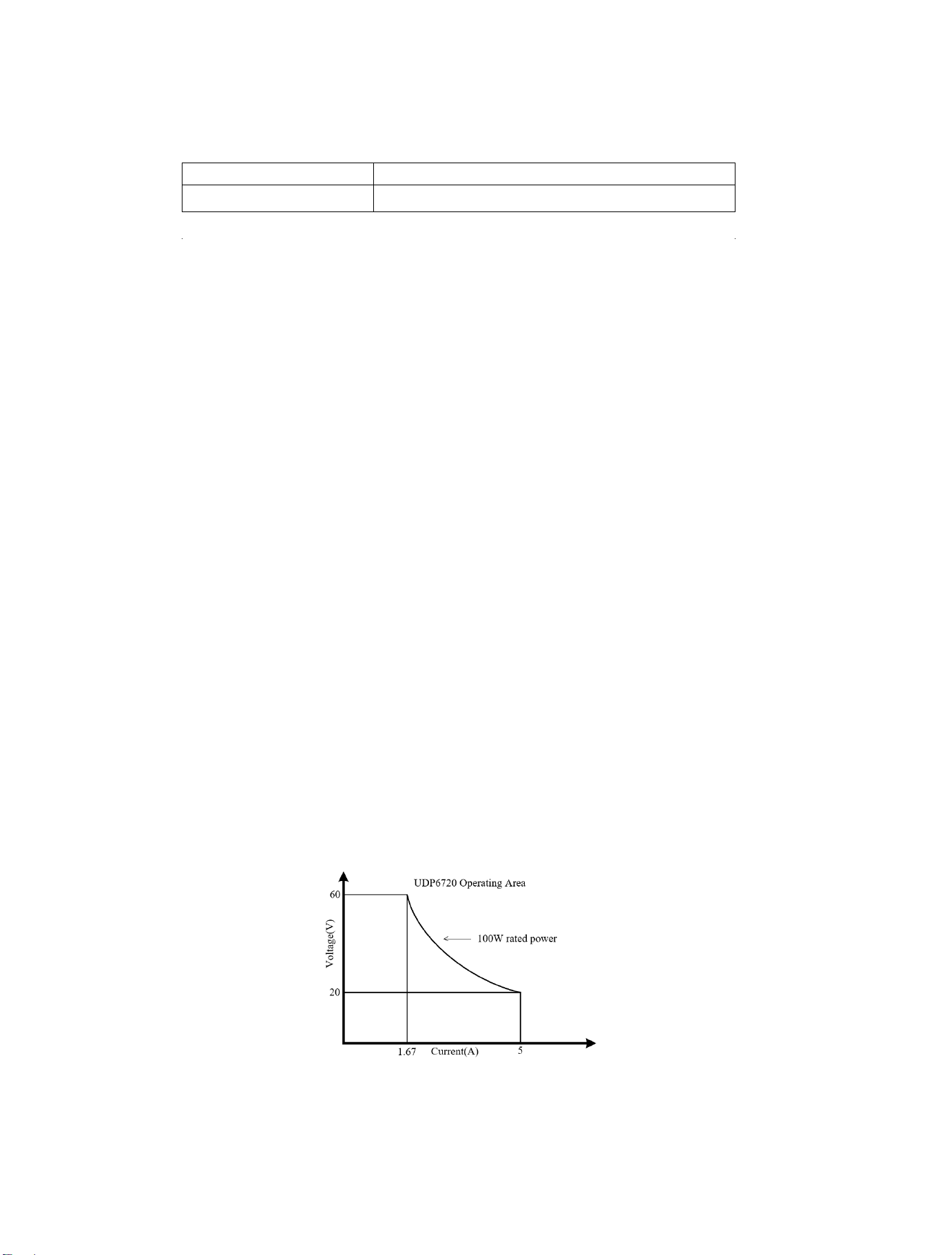
The PS605 digital control power supply with widest voltage and current range, it can applied in many fields.
Take PS605 for example, with max power 100W and ouput adjustable in 60V/5A, auto control voltage and current slew
rate, power rate up to three times rapid than other similar products. One instrument can replace three models
(60V×1.6A/32V×3A/20V×5A), save your repeat investment.
Example
Take the PS605 for example,set output voltage as 60V, because the max power of PS605 is 100W, so the max output
current is 100W/60V=1.66A. When output voltage down to 20V, the max output current turns to 100W/20V=5A. The max
output current of PS605 is 5A, if the current output voltage continue decrease , the max output current of PS605 still as 5A.
PS605 Operating Curve
6
Specifications
Specification
PS605
Output Range
Voltage
0~60V
Current
0~5A
Power
100W
Load Regulation
Voltage
<0.01%+3mV
Current
<0.01%+3mA
Power Supply
Regulation
Voltage
<0.01%+3mV
Current
<0.1%+3mA
Programming
Accuracy
Voltage
<0.05%+10mV
Current
<0.2%+2mA
Read-back Accuracy
Voltage
<0.05%+10mV
Current
<0.2%+2mA
Ripple and Noise
Voltage
<2.0mV rms
Current
<5.0mA rms
Dimension
W×H×D
87×174×255(mm)
Weight
Net
<2.5Kg
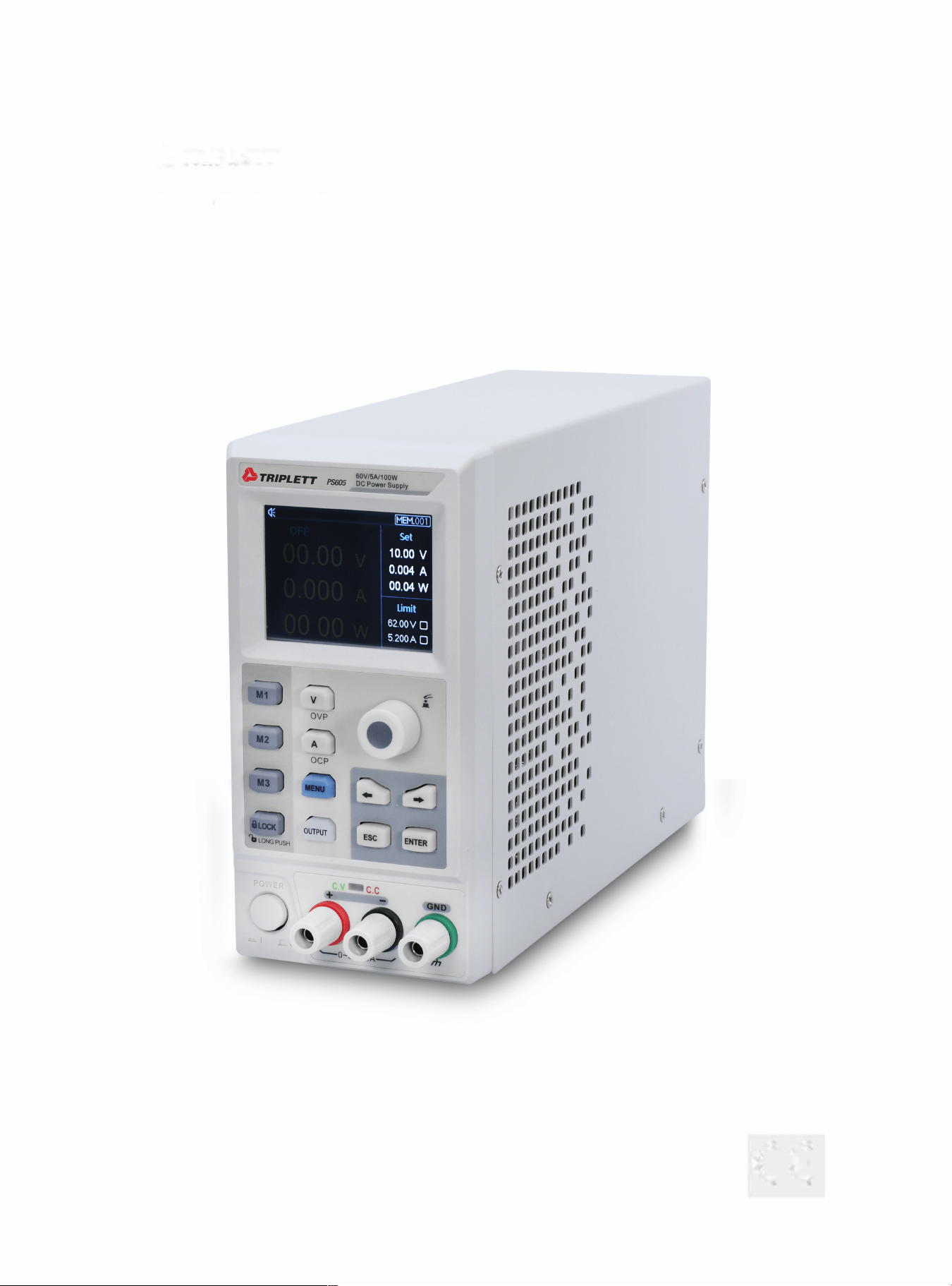
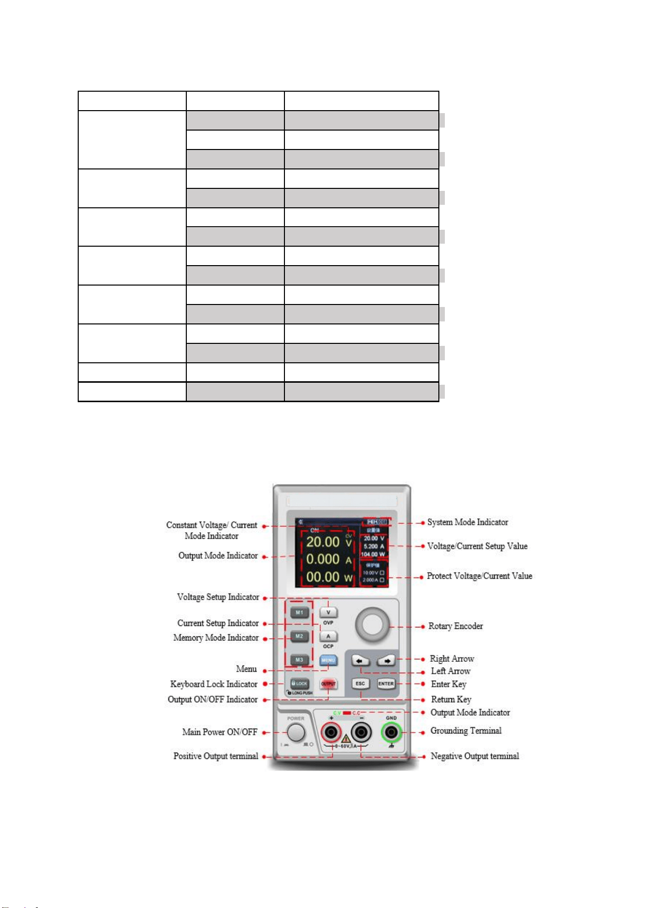
Front Panel
7
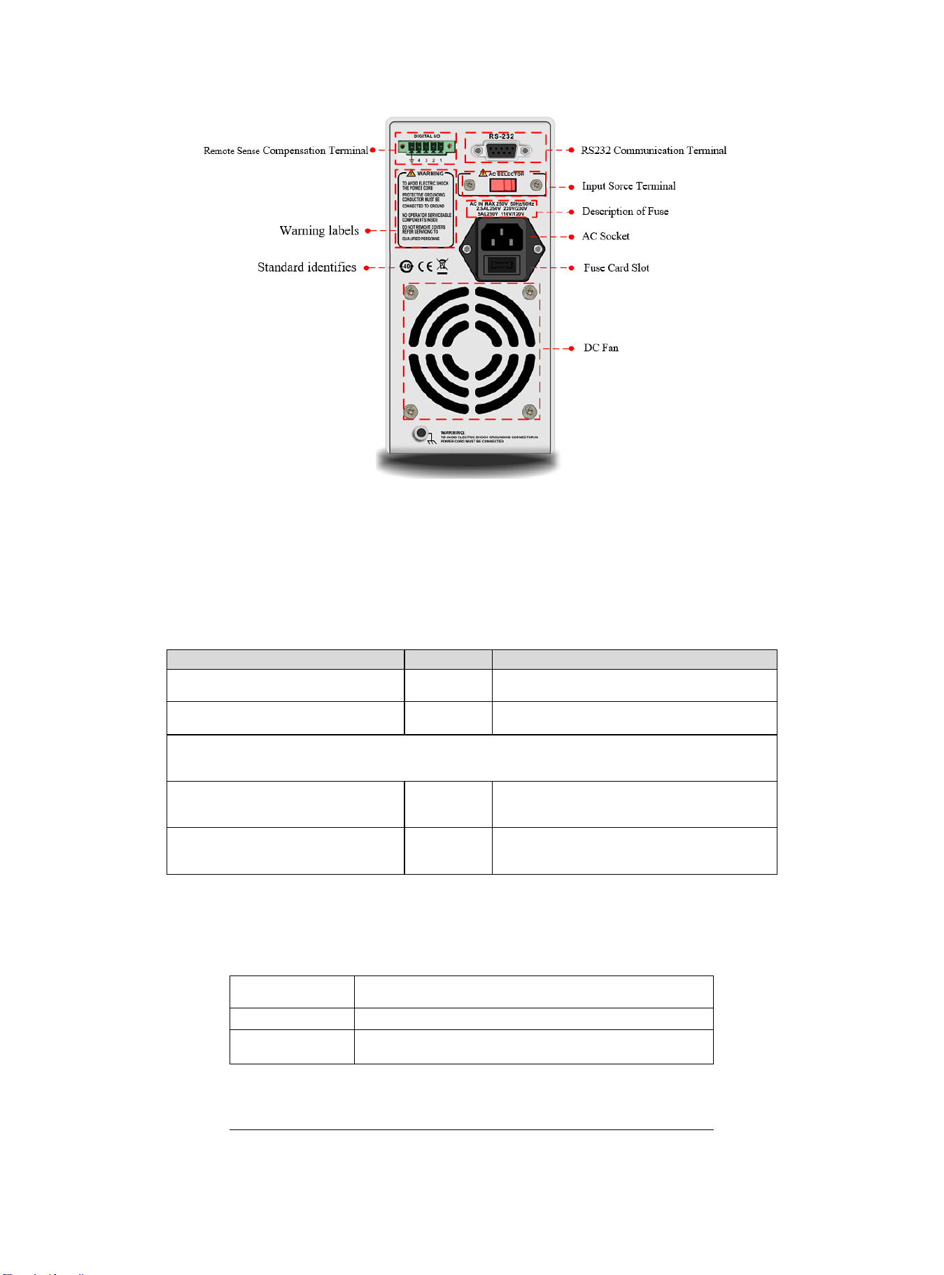
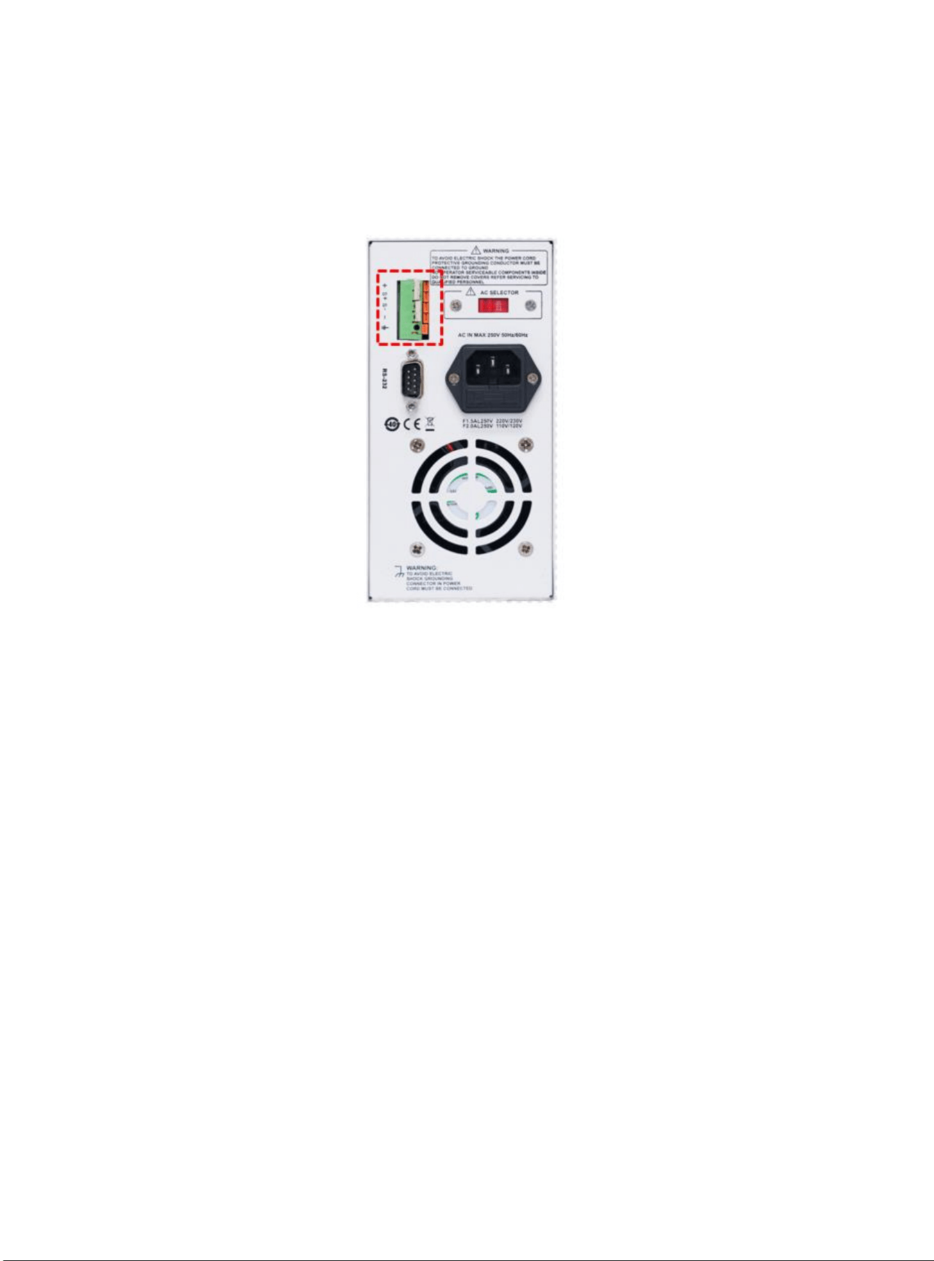
Rear Panel
Packing List
Befor use the instrument, please,
1.Check whether the appearance is damaged, scratched or has other defects;
2.Check with packing list to confirm that accessories has no loss.
If there have any problem, please contact with Uni-Trend Instrument Sale Department or the
distributor.
Components
Quantity
Remarks
The instrument
1
The model is subject to the actual order
3C power line
1
250V/5A spare fuse
PS605
1
User’s Manual /Upper-computer
software
1
Electronic file,download from the
official website
Requirments of Power Supply
PS605 power supply can only use under the power supply terms as the table below.
Parameter
Requirements
Voltage
AC110/ 220(±10%)V
Frequency
50/60Hz
Factory supply three-core power cable, please make sure power cable of three phase
8
socket is connect with ground before use.
This instrument 110V is select fuse of 250V/3.15A or 250V/5A, the specification is 5×
20mm,it all set and equip with spare fuse of 250V/3.15A or 250V/5A in fuse box before
the product leave the factory.
Please remove the external power cable before replace the fuse, open the fuse socket
slot under the power supply plug, take out the old fuse and replace the new fuse into it,
after that the instrument can be used normally.
Warning:Do not use power cable with any signs of damage to avoid danger!
Operating Environment
UDP6720 series digital control power supply can only use in normal termperature and low
condensing zone. The general environmental requirements of the instruments is listed as the below
table.
Operating Environment
Environmental Requirements
Temperature
0℃~45℃
Humidity
20%~80%(non- condensation)
Storage temperature
-20℃~70℃
Altitude
≤2000 meter
Pollution degree
2
Explanation:In order to guarantee the accurancy of measurement, it is suggested that turn on the instrument
half an hour before operating.
Cleaning
To prevent from the risk of electric shock, please pull out power line befor cleaning.
Please use a clean cloth dipped in clean water to clean the cover and panel.
Do not clean the inside of the instrument.
Caution:Do not use solvents (alcohol or gasoline etc.) to clean the instrument.
Quick Start
Apparance Inspection
1. Check out the instrument is in a good condition during the delivery. If there have any problem, please contact with Uni-
Trend Instrument Sale Department or the distributor.
2. Confirm whether the AC input voltage of PS605 complies with the standards of your country or region.
Notice: Use 110V/220V switch on the rear panel to select input voltage. After confirming the above matters, power on
the instrument.
9
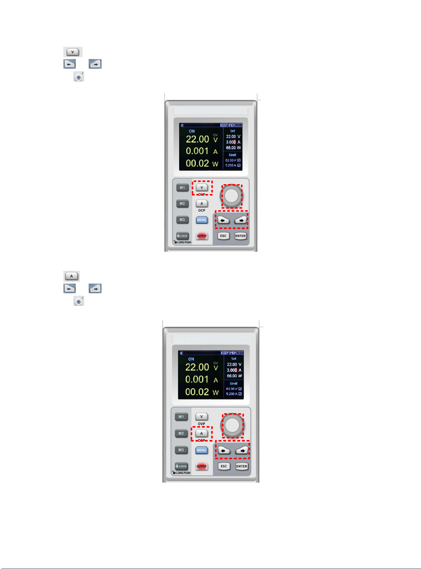
Voltage Setup
1) Push key to set voltage value;
2) Push or to select the specific numeric field;
3) Rotating to enter the definited voltage parameter.
1
2
3
Current Setup
1) Push key to set current value;
2) Push or to select the specific numeric field;
3) Rotating to enter the definited current parameter.
1
2
3
10
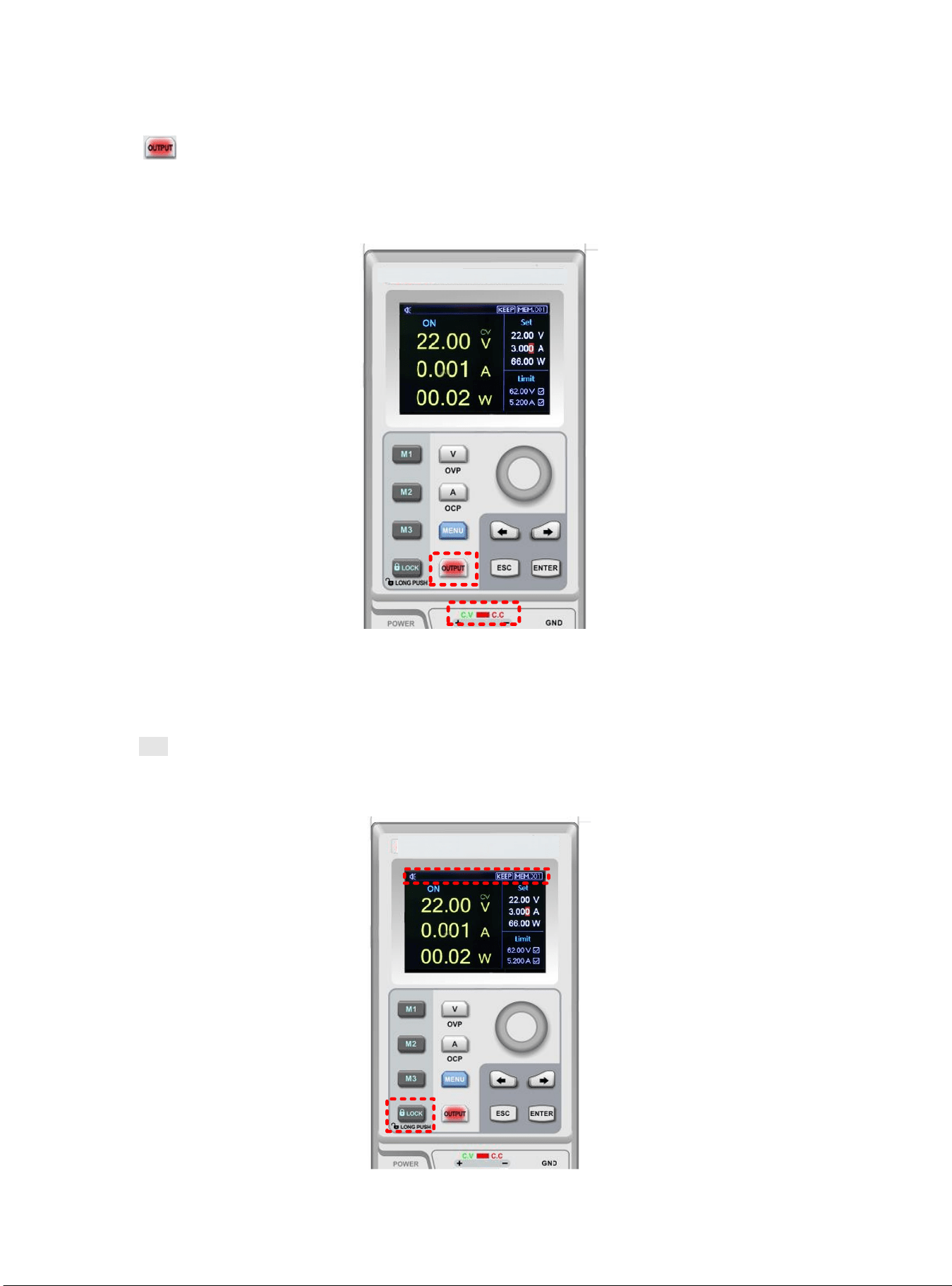
Enable Output
1) Push to enable power output function and the indicator light will be green. In the mean time, C.V/C.C indicator
light will be green or red light according to the different output mode;
2) OUTPUT key indicator light will be off when OUTPUT function is disable. C.V/C.C indicator light will also be off.
Keyboard Lock
Lock keyboard function is prevent unauthorized worker or operating personnel form making accident operation. To avoid
damage the device under test.
1) Push Lock key to enable lock keyboard function and the indicator light will be green. Lock symbol will shown on the top
of screen.
2) In lock status, long push Lock key to unlock the function and indicator light will be off. Lock symbol will also disappear
on the screen.
11
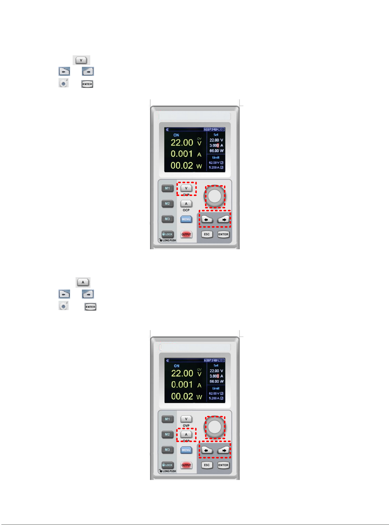
OVP Function
1) Long push key to set OVP function;
2) Push or to select the specific numeric field and enter OVP parameters;
3) Push or to enable OVP function;
4) When the OVP function set successfully, ☑ mark will shown beside OVP parameters.
1
2
3
OCP Function
1) Long pushk key to set OVP function;
2) Push or to select the specific numeric field and enter OCP parameters;
3) Push or to enable OCP function;
4) When the OCP function set successfully, ☑ mark will shown beside OCP parameters.
1
2
3
12
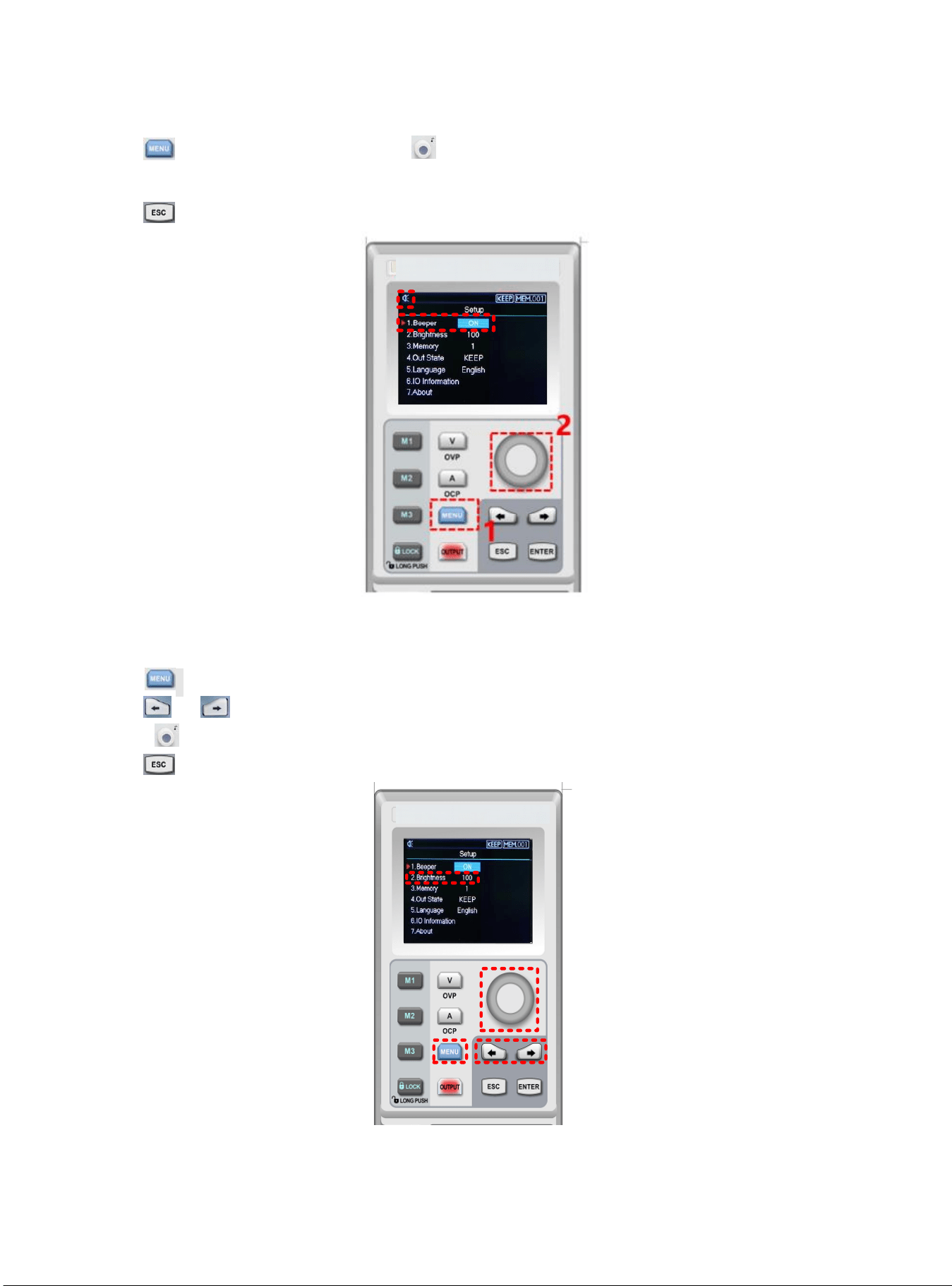
Bepper Switch
1) Push to enter the setup interface, rotate to adjusting buzzer mode;
2) When the buzzer function is enable, keyboard sound is also turn on; when the buzzer function is disable, keuboard sound
will be silent. Buzzer status will shown on the top screen.
3) Push to exit the setup page.
3
Brightness Setup
1) Push to enter the setup interface;
2) Push or to select Brightness field;
3) Rotate to set the brightness, adjusting range 0~100%;
4) Push to exit the setup page.
1
2
3
13
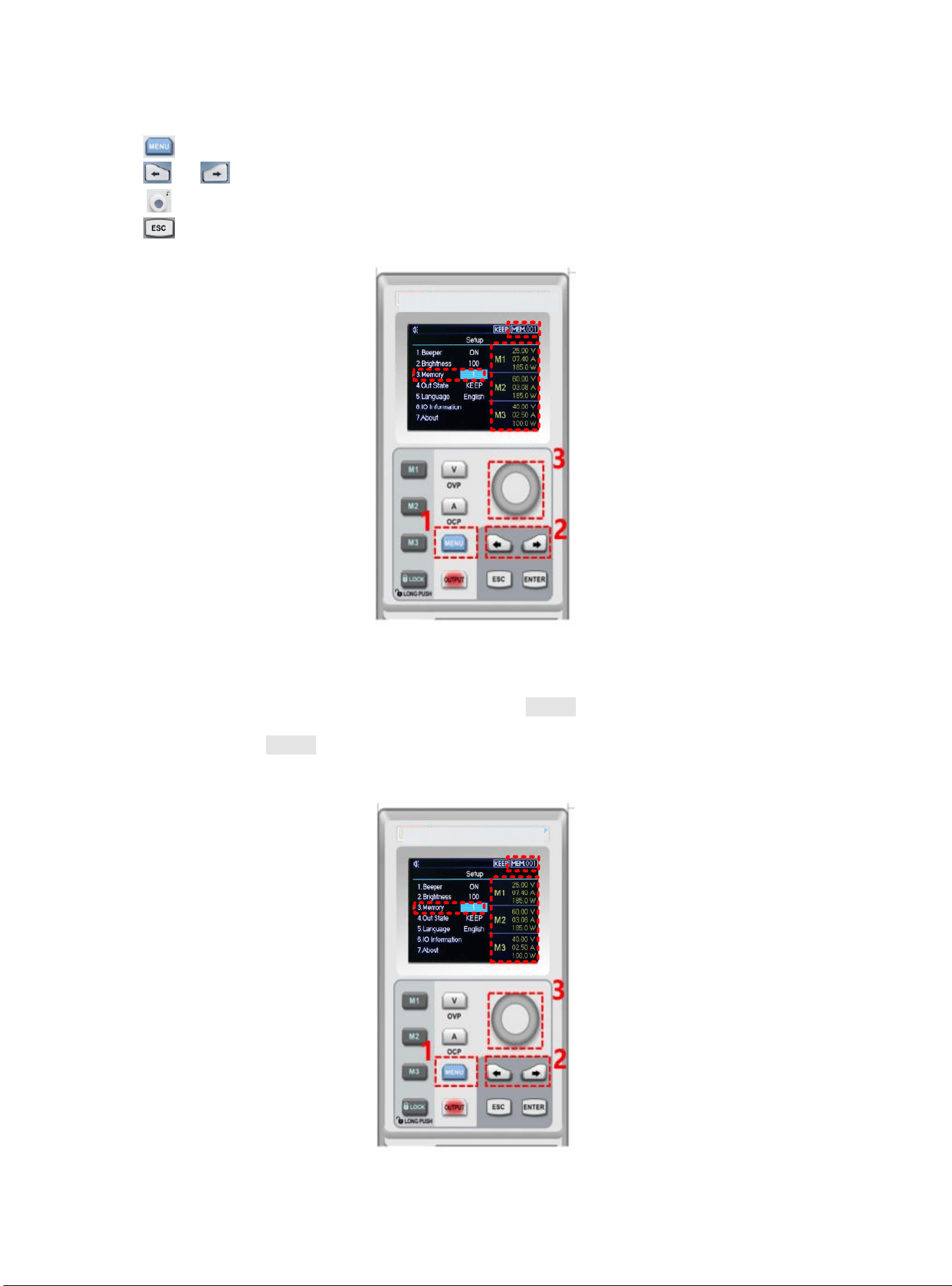
Memory Group Setup
1) Push to enter setup interface;
2) Push or to select Memory option;
3) Rotate to set memory group, the maximum range is 200;
4) Push to exit the setup page.
Memory Group Voltage/Current Setup
Set the specific output voltage/current point and select memory key M1~M3, push it to save the current setting.
When user need to call the stored output voltage/current, enter the setup interface to select the specific memory group
and then push memory key M1~M3 to call the specific stored output voltage/current.
When user call the stored output voltage/current, the corresponding memory key will indicate green light.
14
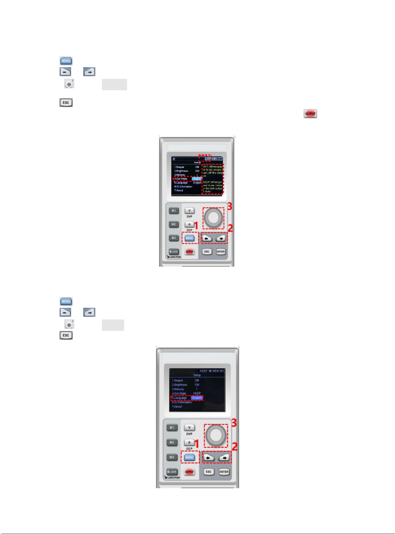
Output Mode Setup
1) Push to enter setup interface;
2) Push or to select the output status bar;
3) Rotate to select Out State;
4) Output status symbol will shown on the top screen when output is finished;
5) Push to exit the setup page.
Notice: When output function is operating, power supply should remain enable status. That is, should keep
operating status when turn off the power supply.
Language Setup
1) Push to enter setup interface;
2) Push or to select language field;
3) Rotate to select Languge type (English/Chinese);
4) Push to exit the setup page.
15
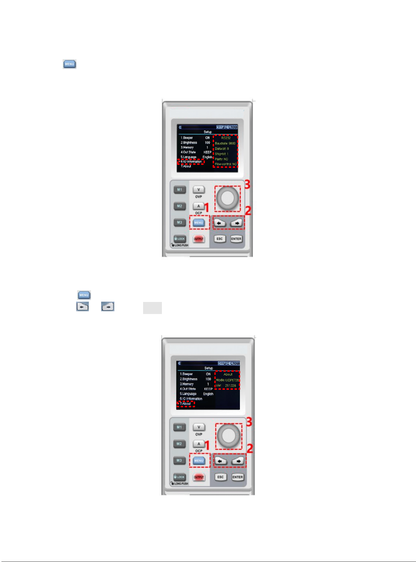
Display Interface Information
1) Push to enter the setup interface;
2) Use left, right arrow key to select the IO Information option;
3) RS232 configuration information will shown on the right side of the screen.
About
1) Push to enter the setup interface;
2) Push or to select About field;
3) The device information product’s model and the current version number will shown on the right side of the
screen.
16
Remote Sense Compensation Setup
Before use Remote Sense compensation function, take off short connect terminal on the Remote Sense compensation
terminal, connect load voltage positive terminal to compensation terminal S+ and load voltage negative terminal connect
to compensation terminal S-. And then enable power output to turn on Remote Sense compensation function. That is,
the output voltage of the DC power supply is the voltage of the load terminal.
Notice: Remote Sense compensation voltage should less than 0.6V.
CV/CC Operating Mode of Power Supply
Power supply can automatic transfer constant voltage/current function. Power supply can ongoing switch the constant
voltage/current function dependends on load fluctuation.
If the current load is on the constant voltage mode, power supply provide a controlled output and voltage. As the load
resistance value decreases, the output voltage remains constant until the output current increases to greater than the
preset current value, which it will convert operating mode. If the power supply turn into constant current output, the
output voltage will decrease proportionally according to resistance value of the load. When the current value less than
the set value, power supply will back to the constant voltage mode.
Troubleshooting
Power supply is no output
1. Check the set value of voltage and current is zero or not. If it is, reset the voltage and crrent value.
2. OUTPUT indicator light is light on or not. If it is, push OUTPUT key to enable the output function.
3. Check OVP,OCP,OTP function is activated or not. If it is, reset the value of OVP, OCP and wait the power supply
remain stable to turn the output function.
4. If Remote Sense compensation function has been enabled, check the line loss of output cable is excced thelimit
value or not. If it is, replace the output cable or decrease the output current, and then try to enable the power
supply again.
The keyboard is not work
Check Lock indicator light is light on or not. If it is, please refer to Lock section to reset again.
17
Remote Communication
The installment and startup configuration file
1. Download the installment file from official website;
2. Turn on power supply;
3. Connect the control line of RS232 to control power supply;
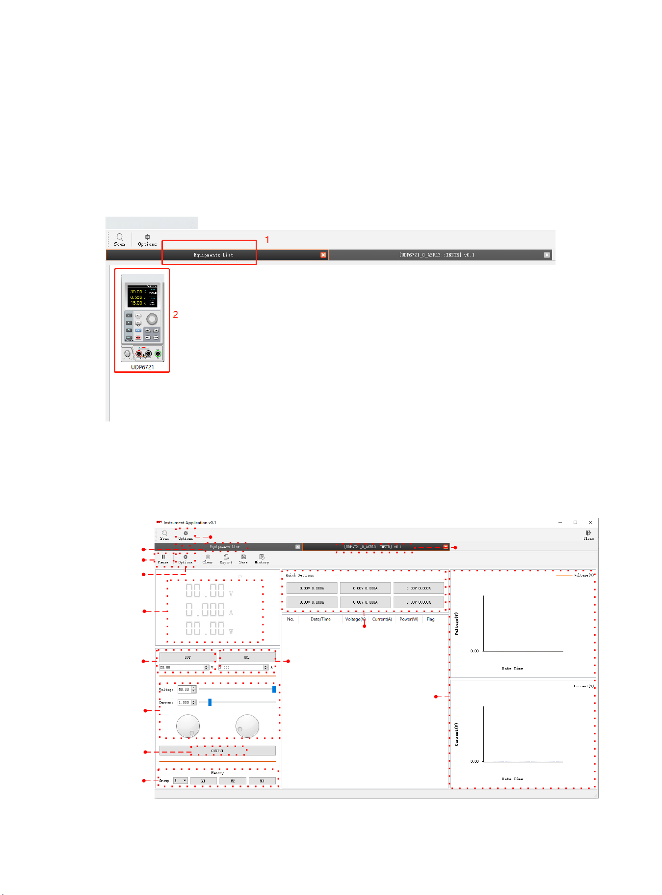
4. Activate the remote controlling application program;
5. Click Euqipments List, and double-click the power supply symbol of PS605 to enter the remote
communication interface.
Remote Control Interface & Operating Instructions
Language Option
Device selection
Operating interface
Pause
Data acquisition
configuration
Power output display
OVP protection
OCP protection
Voltage/Current setup
ON/OFF
Memory group setup
Output record of voltage/current
Quick set of voltage/current
18
List Mode (Time Function) and Delayer Mode
List Mode
List mode can setup multiple testing program, it can set 48 groups of independentant voltage, current and parameter of
output duration time.
Delayer Mode
Delayer mode can setup multiple testing program to control output status, which is set count to control output status is
on or off, and the time interval of switch can also set by point to point. Delayer mode can set 48 output status groups to
control parameter.
Output parameter of list/delayer mode can all store in internal storage. It has powerdown function. Storage space for
each group is 48
Operating Steps
1. Push power supply switch to turn on the instrument;
2. Turn on list mode/ delayer mode:
Push arrow key or to enter setup interface of list/delayer mode. It can be circular switch.
Notice:
a.List/delayer mode and channel output function can’t use at the same time, it can only choose either-or;
b.When List mode status is pause, delayer mode can’t set parameter. It should enter setup interface of list mode to switch
to , and the status is pause and then to set parameter;
3. Connect with load;
4. Set parameter of list/delayer mode;
Please refer to section Parameter Setting of List Mode and Parameter setting of Delayer Mode.
5. Enable timing/delayer output;
In timing/delayer interface, rotate rotary knob to and push to enable timing/delayer output
function. Symbol turn to and status bar will also change to “stop” to “run”;
6. Disable timing/delayer output;
In timing/delayer interface, rotate rotary knob to and push to disable timing/delayer output function.
Symbol turn to and status bar will also change to “run” to “stop”;
Another shorcut to disable output function, push key to turn off timing/delayer function in any interface.
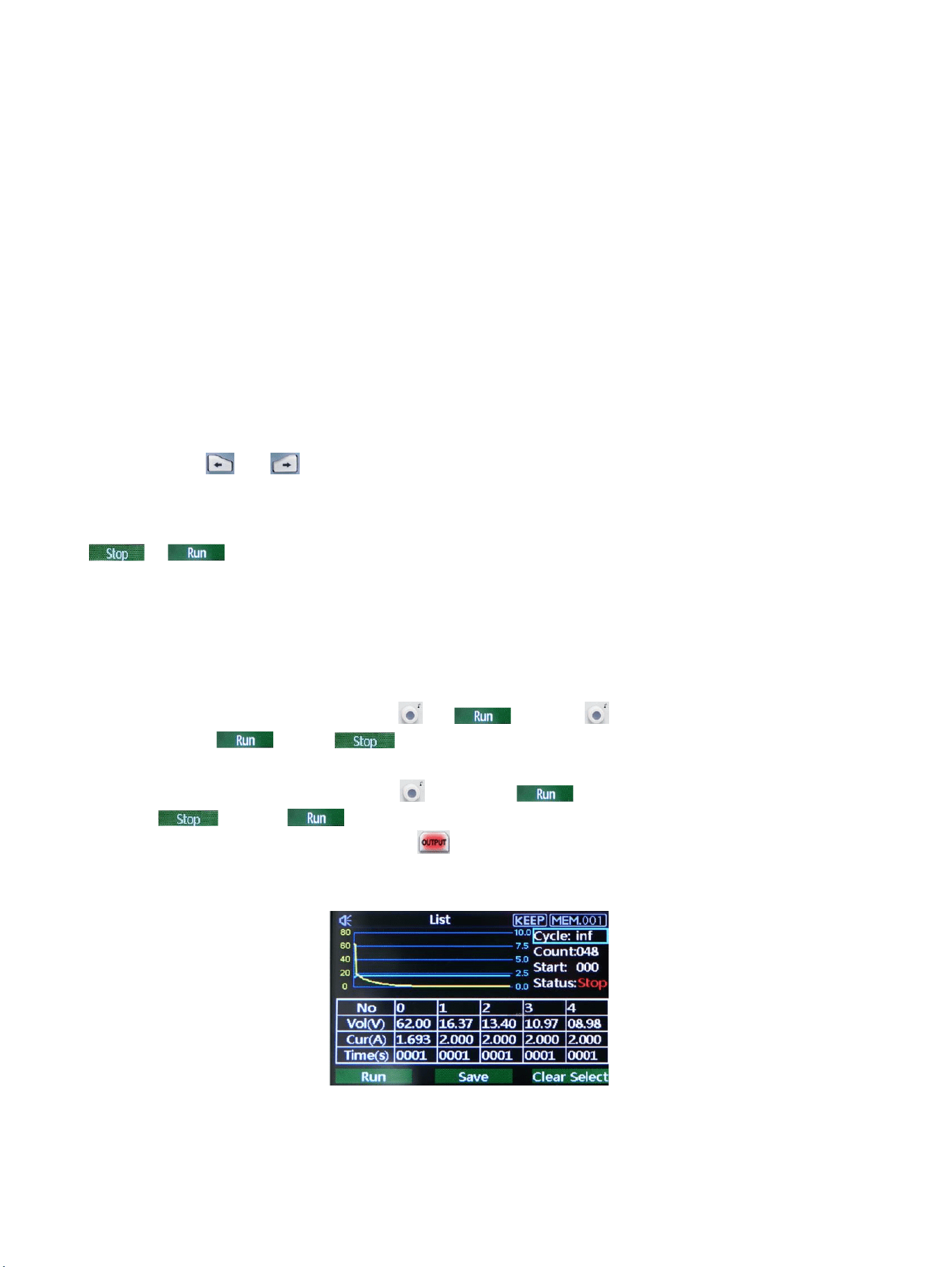
Parameter Setting of List Mode
Interface of List Mode
19
Menu introduction of list mode
Cycle index:It divide into maximum inf and 1-999. A cycle period is start form setup origin point to end point. Push
rotary knob to adjusting parameters.
Count: It can set “001” - “048”, which is excute group from origin point to end point. Push rotary knob to adjusting
point. Notice: each voltage, current and time is a point.
Origin point: It can adjust “000”-“047”, which is start from origin point to run. (“origin point” value + “count” value
≤ 048)
Mode: It divide into three mode stop, run and pasue, it can not be set;
Pause presents power supply is not output at the current;
Run presents power supply is operating;
Pause presents power supply is paused;
Notice:In pause and run mode, interface can not be adjust; pause only shown when indicator is off and only
shown on interface.
The Curve Figure of Count Parameter
This curve figure can direct present the setting parameter of list mode.
Count Configuration Table of List Mode
Table setting:serial number of each group is corresponding to voltage, current and time value, push rotary knob
to set parameter;
Voltage:adjust the actual output voltage value;
Current:adjust the current value;
Time:duration output time value in this serial number;
, : operating status at the current, push rotary knob to switch mode;
Save: save the setting parameter for powerdown function, push rotary knob to save the current setting;
: clear parameter values in the table all to zero (voltage 00.00, current 00.00, time 00.00), push rotary knob
to eliminate the setting parameter values in the table;
Notice: clear select function is eliminate the corresponding group of origin point to count.
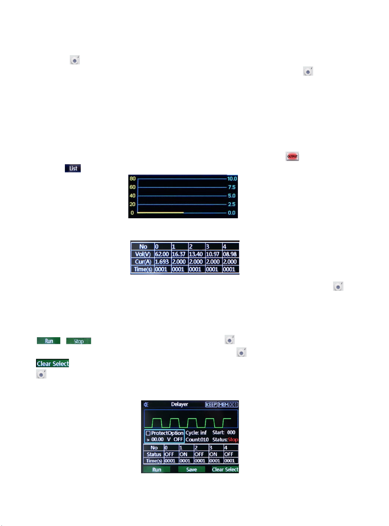
Parameter Setting of Delayer Mode
Interface of Delayer Mode
20
It presents power output status and delayer time of user configuration,it’s convenient to view the data.
Protection setting:this function can set protection value of voltage, current and power, push rotary knob
select “√”to turn on protection function;
Cycle index:It divide into maximum inf and 1-999. A cycle period is start form setup origin point to end point;
Count:It can set “001” - “048”, which is excute group from origin point to end point. Push rotary knob to
adjusting parameter;
Origin point: It can adjust “000”-“047”, which is start from origin point to run. Push rotary knob to adjusting
parameter (“origin point” value + “count” value ≤ 048)
Mode: It divide into three mode stop, run and pasue, it can not set;
Stop presents power supply is not output at the current;
Run presents power supply is operating;
Pause presents power supply is paused;
Notice:In pause and run mode, interface can not be adjust; pause only shown when protection function is enabled.
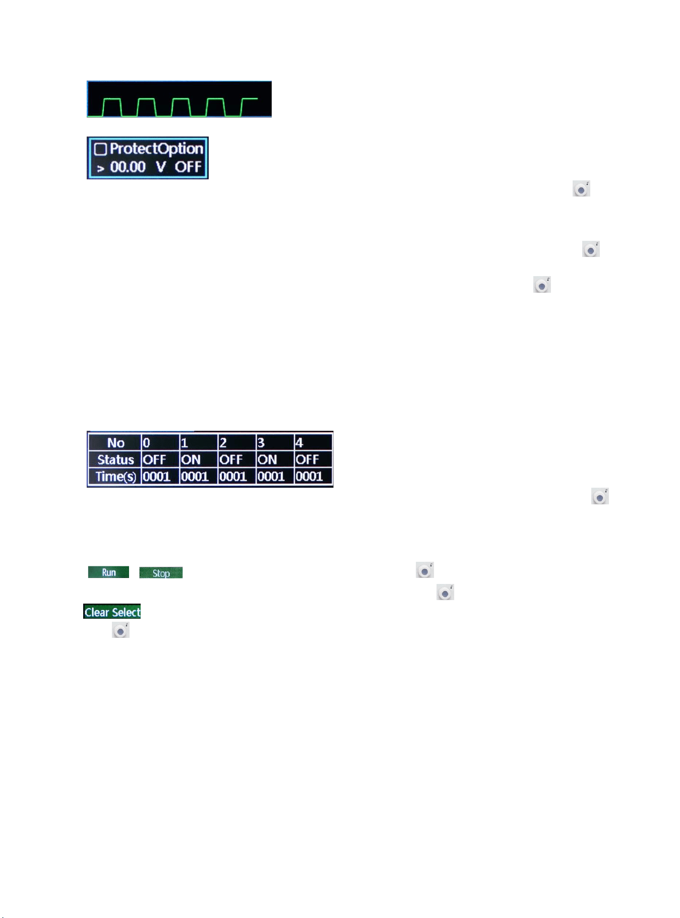
Table setting:serial number of each group is corresponding to output status and delay time, push rotary knob
to set parameter
Mode:ON presents output function is enabled, OFF presents output function is disabled
Time:set the delay time of the main interface;
, : operating status at the current, push rotary knob to switch mode;
Save: save the setting parameter for powerdown function, push rotary knob to save the current setting;
: clear parameter values in the table all to zero (voltage 00.00, current 00.00, time 00.00), push rotary
knob to eliminate the setting parameter values in the table;
Notice: clear select function is eliminate the corresponding group of origin point to count.
20