

UHF Card Reader
User Manual

UHF Card Reader User Manual
Copyright © Hangzhou Hikvision Digital Technology Co., Ltd. 2019. All rights reserved.
Any part of this manual, including text, pictures, graphics, etc., belongs to Hangzhou Hikvision
Digital Technology Co., Ltd. or its subsidiaries (hereinafter referred to as "the Company" or
"Hikvision"). Without written permission, no unit or individual may excerpt, copy, translate, or
modify all or part of this manual in any way. Unless otherwise agreed, our company does not
provide any express or implied representations or warranties in this manual.
About this manual
The products described in this manual are intended for sale and use in Chinese mainland only.
This manual is used as a guide. The photos, graphics, charts and illustrations provided in the manual
are for explanation and illustration purposes only and may differ from the specific product. Due to
product version upgrade or other needs, the company may update this manual, if you need the
latest version of the manual, please log on to the company's official website to check
(www.hikvision.com).
Hikvision recommends that you use this manual under the guidance of a professional.
Trademark Notice
is a registered trademark of Hikvision. Other trademarks mentioned in this manual
are the property of their respective owners.
Disclaimer
To the fullest extent permitted by law, the products described in this manual (including their
hardware, software, firmware, etc.) are provided "as is" and may be defective, wrong or
malfunctional, and the Company does not provide any form of express or implied warranties,
including but not limited to warranties of merchantability, satisfactory quality, fitness for a
particular purpose, non-infringement of third party rights, etc., and shall not compensate for
any special, incidental, incidental or consequential damages arising from the use of this manual
or the use of the Company's products, including but not limited to loss of business profits,
Losses arising from loss of data or documents.
If you access the product to the Internet at your own risk, including but not limited to the
product may be subject to network attacks, hacker attacks, virus infection, etc., the company will
not be responsible for the abnormal operation of the product, information leakage and other
problems caused by this, but the company will provide you with product-related technical
support in a timely manner.
When using this product, please strictly follow the applicable laws. The Company shall not be
liable if the Product is used for infringement of the rights of third parties or other improper uses.
In the event of a conflict between the contents of this manual and applicable laws, the
provisions of the law shall prevail.
UHF Card Reader User Manual
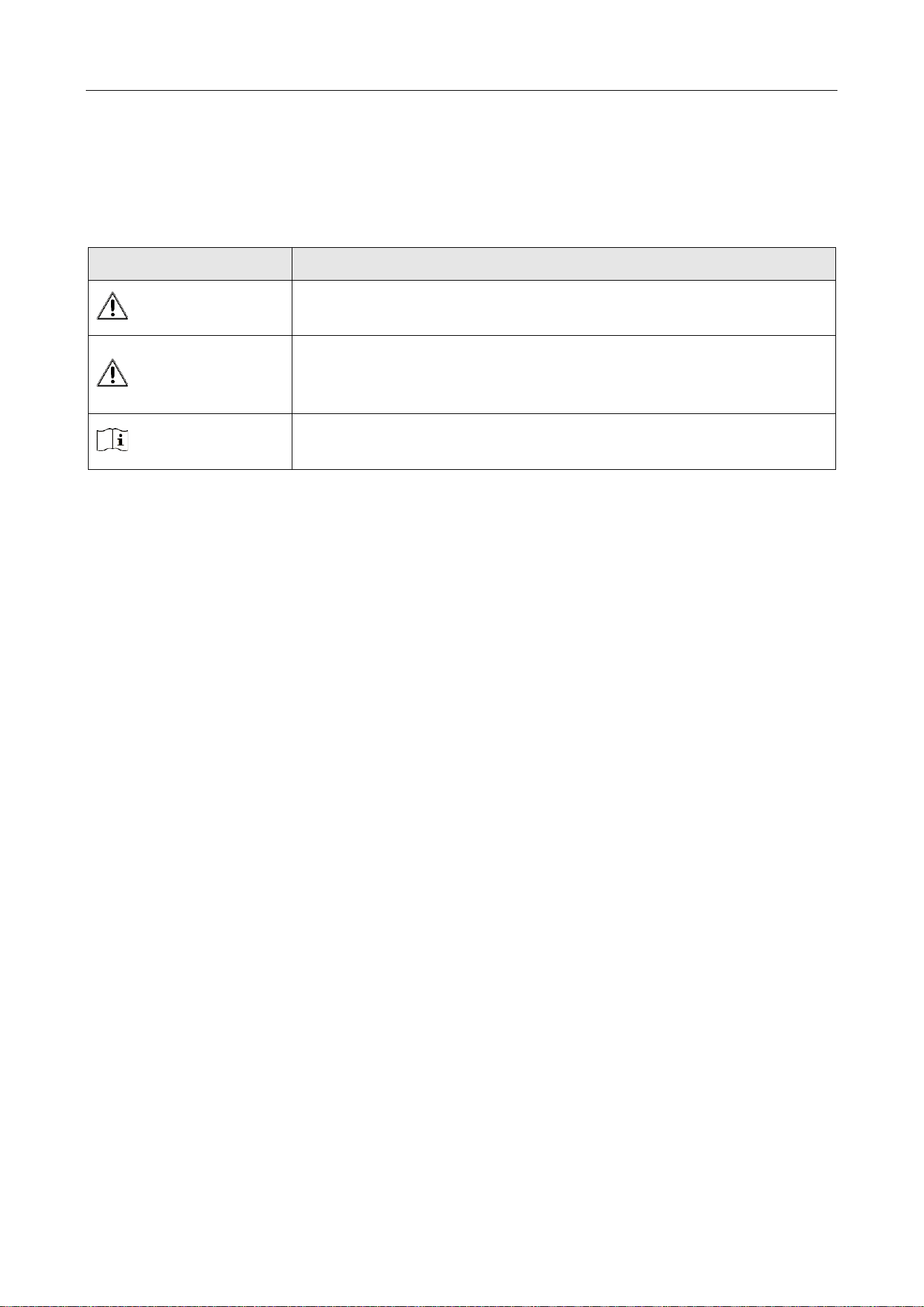
Symbol Conventions
The symbols that may be found in this document are defined as follows.
Symbol
Description
Danger
Indicates a hazardous situation which, if not avoided, will or could
result in death or serious injury.
Caution
Indicates a potentially hazardous situation which, if not avoided,
could result in equipment damage, data loss, performance
degradation, or unexpected results.
Note
Provides additional information to emphasize or supplement
important points of the main text.

UHF Card Reader User Manual
Contents
Chapter 1 Introduction ................................................................................................................................ 1
1.1 Product Introduction ......................................................................................................................... 1
1.2 Packing List ........................................................................................................................................ 2
Chapter 2 Installation and Wiring ............................................................................................................... 4
2.1 Installation ........................................................................................................................................ 4
2.1.1 Mounting bracket instructions ................................................................................................... 4
2.1.2 Installation Schematic and Test Data Reference ......................................................................... 5
2.2 Wiring ................................................................................................................................................ 6
Chapter 3 Reader Configuration .................................................................................................................. 7
3.1 Login web page .................................................................................................................................. 7
3.2 Basic configuration ............................................................................................................................ 8
3.2.1 Network configuration ............................................................................................................... 9
3.2.2 Working mode ...........................................................................................................................10
3.2.3 Event configuration ...................................................................................................................15
3.2.4 System maintenance .................................................................................................................16

UHF Card Reader User Manual
1
Chapter 1 Introduction
1.1 Product Introduction
Compatible with EPC C1 Gen2/ISO 18000-6C.
Carrier cancellation function for better anti-interference capability.
Supports EPC Dense Read Mode (DRM) for long range reading with RF output power up to 33dBm.
Flexible configuration and parameters for maximum tag reads and optimal performance.
Figure 1-1 DS-TRD902-1 Reader appearance
UHF Card Reader User Manual
2
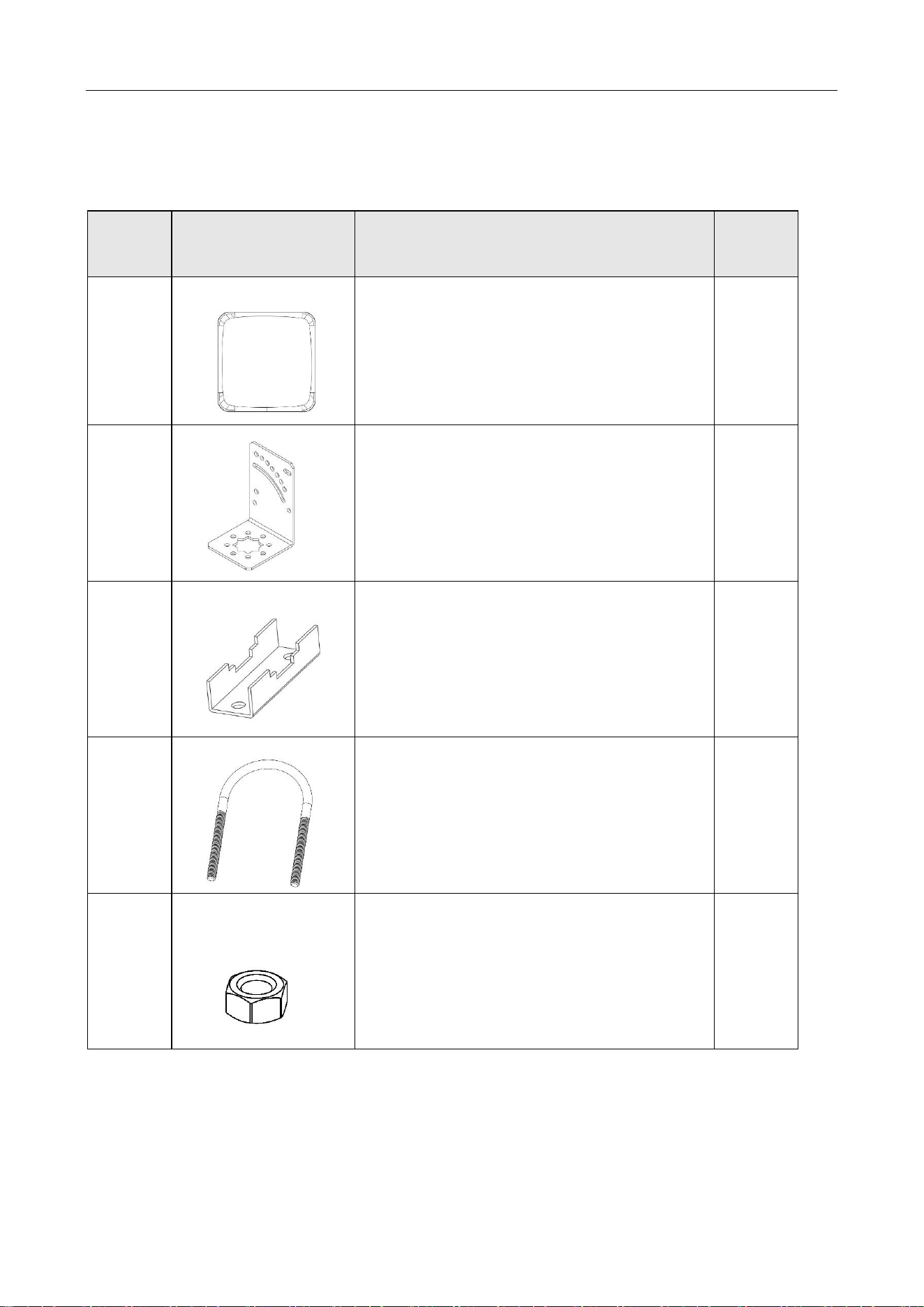
1.2 Packing List
Table 1-1 Packing List
No.
Diagram
Name
Quantity
1
UHF Integrated Reader
1
2
L-shaped Chuck
1
3
N-shaped Chuck
2
4
U-shaped Chuck
2
5
Hex Nut
4
UHF Card Reader User Manual
3
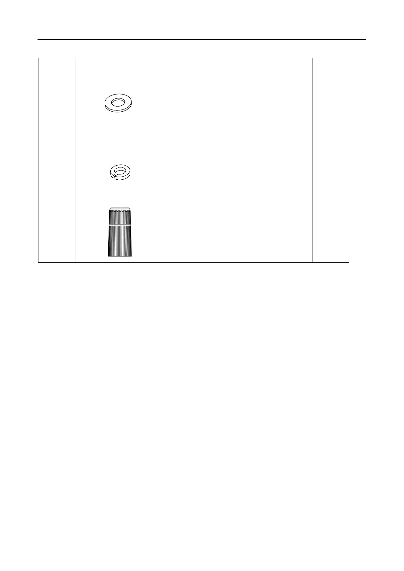
6
Flat Gasket
4
7
Spring Washer
4
8
RJ45 Docking Connector
1
UHF Card Reader User Manual
4
Chapter 2 Installation and Wiring
2.1 Installation
Place the device on a flat, dry fixing table or hang it on the wall.
Keep the environment around the device as dry and well-ventilated as possible.
Ensure that there are no devices in the same UHF band near the installation site to avoid mutual
interference
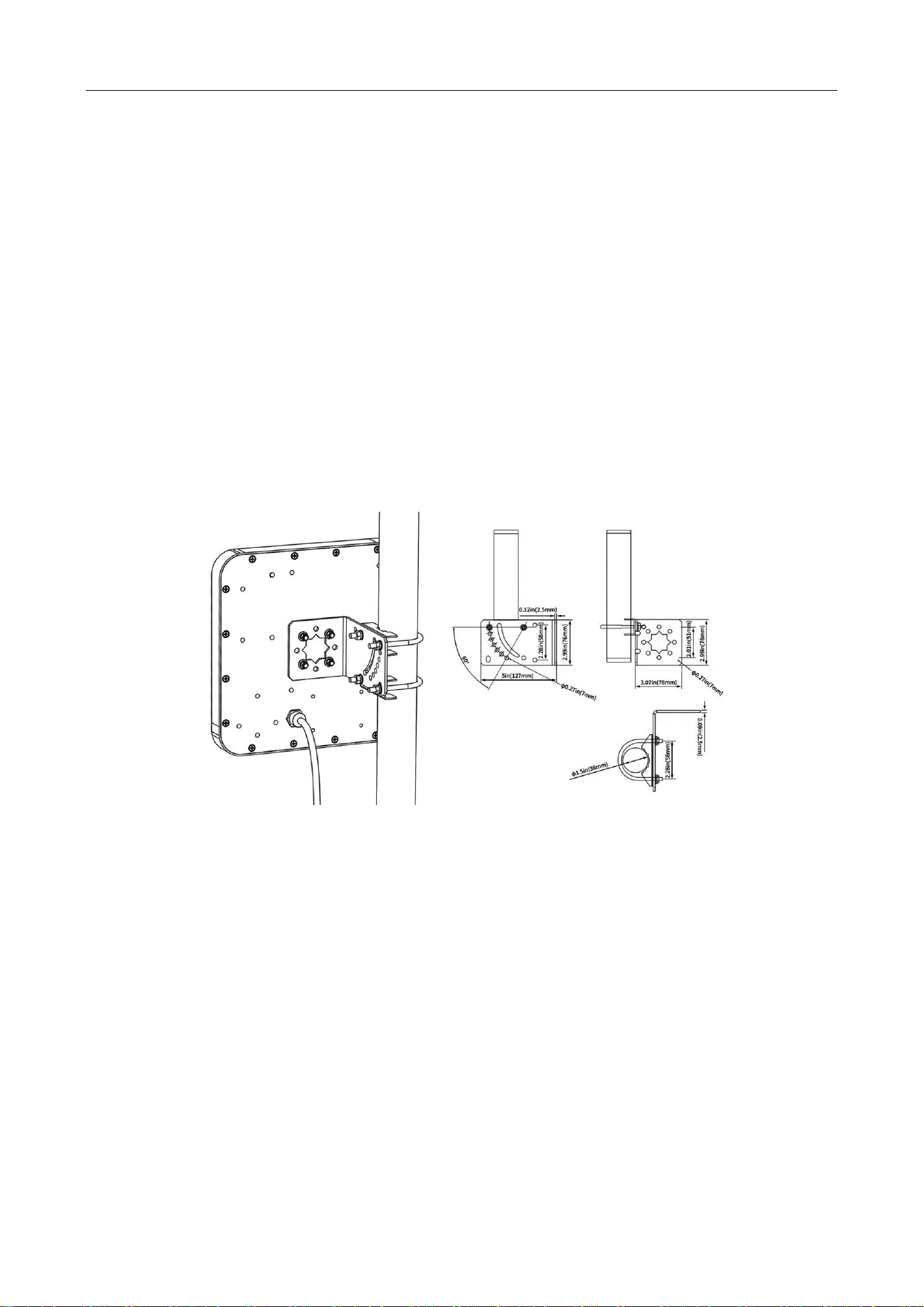
2.1.1 Mounting bracket instructions
The bracket is suitable for round pole with diameter 25-50MM.
Bracket adjustable angle 60 ° (such as adjusting the angle of installation only use a clamp)
Figure 2-1 Mounting bracket
UHF Card Reader User Manual
5
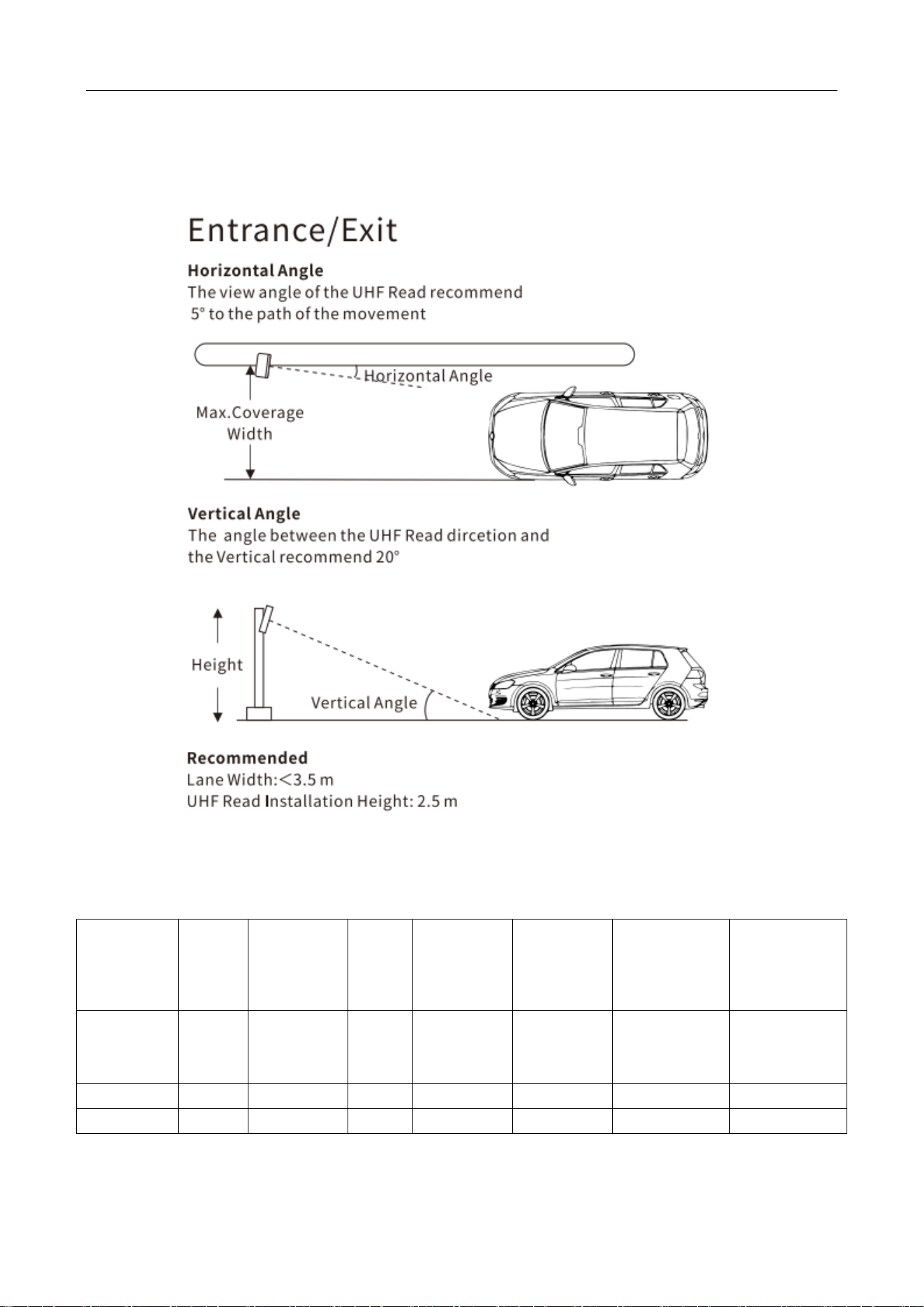
2.1.2 Installation Schematic and Test Data Reference
Figure 2-2 Equipment Installation Schematic
Table 2-1 Data Reference
Equipment
Installation
Location
Setting
power
(dBm)
Equipment
height(m)
Tag
height
(m)
Vertical
angle of
equipment
Horizontal
angle of
equipment
Scope of
identification
(Horizontal
Tag) (m)
Scope of
identification
(Vertical Tag)
(m)
Roadside
30
2.5
1
20°
5°
0-10
0-7
Roadside
25
2.5
1
20°
5°
3-5.5
0.5-4.5
Roadside
20
2.5
1
20°
5°
0
2-2.5
UHF Card Reader User Manual
6
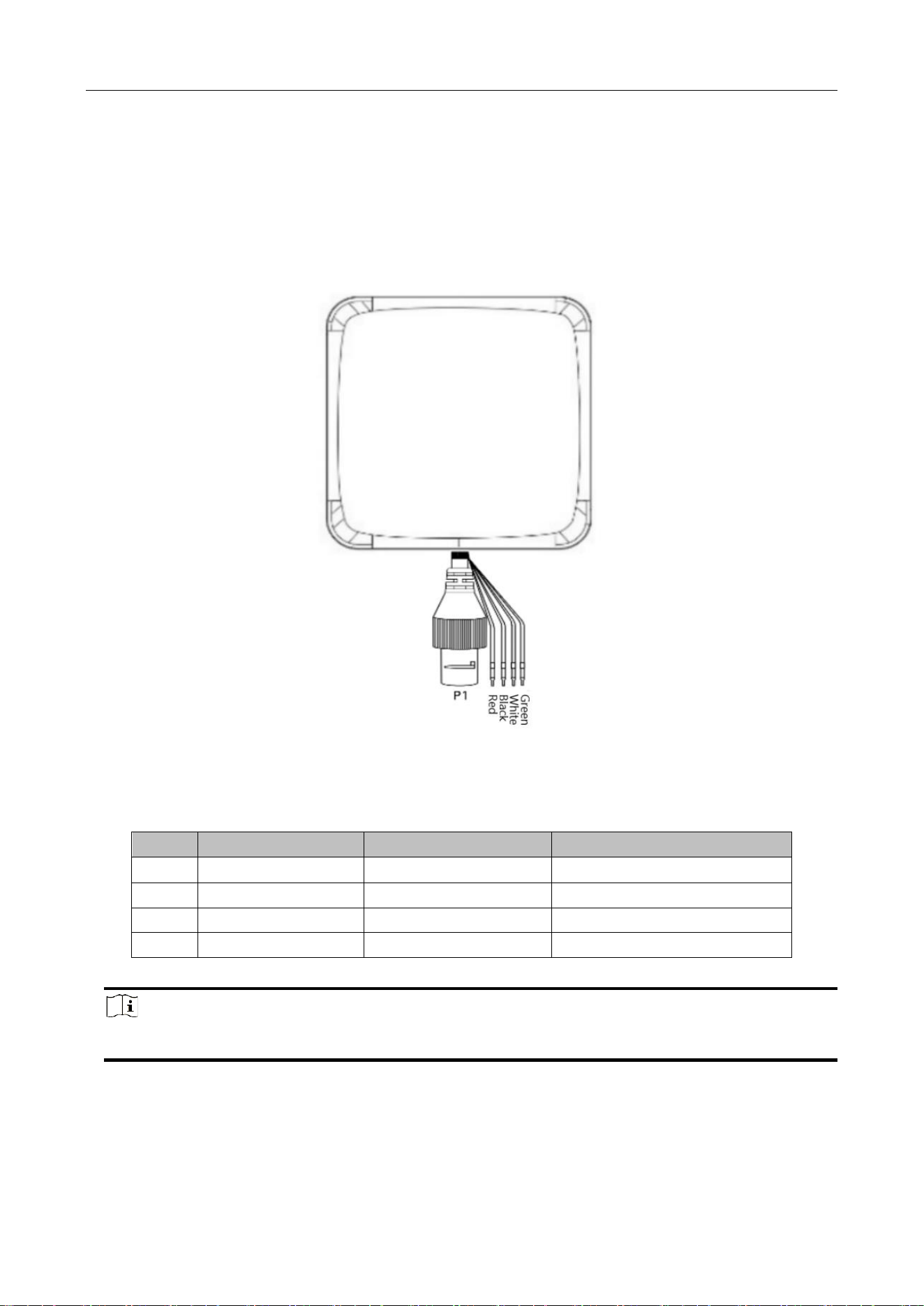
2.2 Wiring
Figure 2-3 Wiring
Table 2-2 Ports Description
SN
Cable colour
Designation
function Definition
1
Red
+12V
Dc power supply positive input
2
Black
GND
Dc Power Ground
3
White
D1
Wiegand Signal Data 1
4
Green
D0
Wiegand Signal Data 2
Note
Each communication line must be used in conjunction with the signal ground return line.
UHF Card Reader User Manual
7
Chapter 3 Reader Configuration
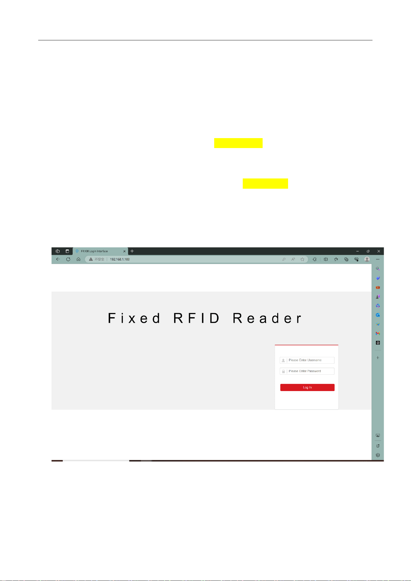
3.1 Login web page
1. Connect the reader to the special power adapter, plug in the network cable and antenna, and
power on the device.
2. Log in to the reader's homepage, the default IP is 192.168.1.100, enter the IP address of the
reader in the address bar of the browser, and the following landing page will appear. Fill in the
user name and password.
3. Enter the user name and password.
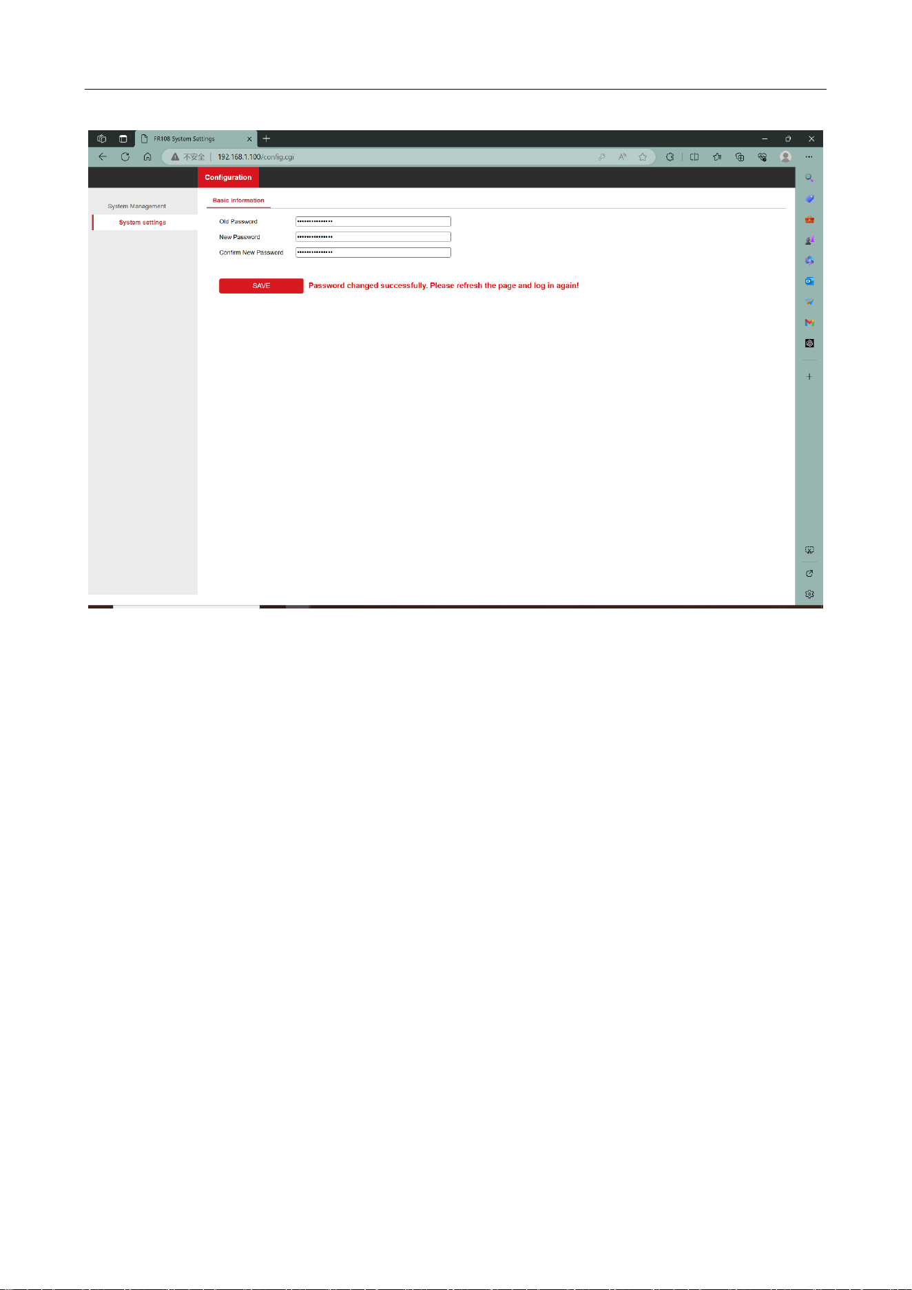
4. The default user name is root and the default password is Hiklife@123+, the first time you log
in, you will enter the password change interface. Enter the default password in the old password
box, enter the user's own configured password in the new password and the new password
confirmation box, then click save and refresh the interface to re-enter the login interface, and then
change the password to the user's configured password and click log in.
Figure 3-1 Enter the web page
UHF Card Reader User Manual
8
Figure 3-2 Change the password
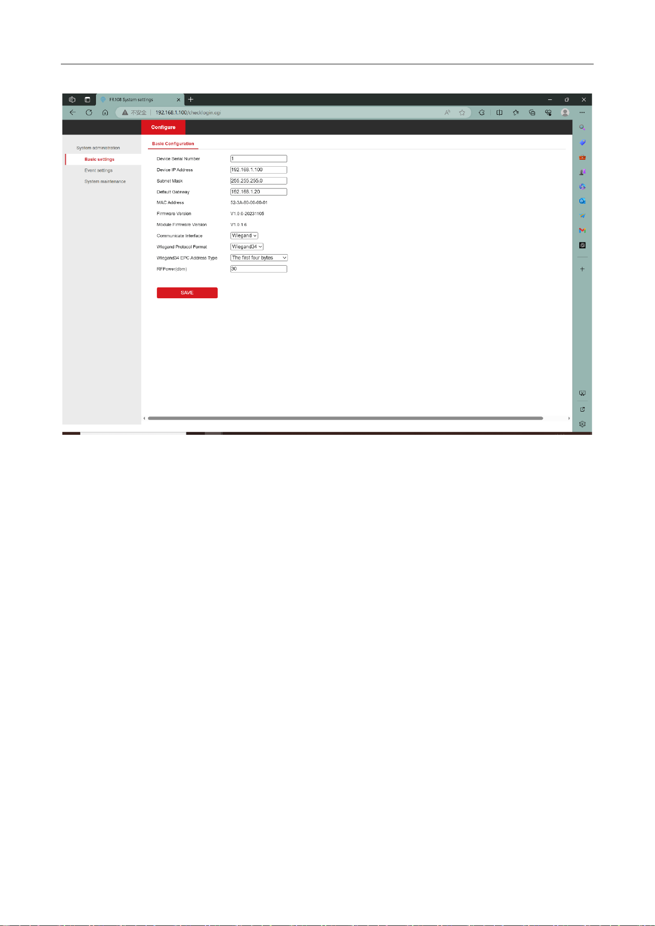
3.2 Basic configuration
In addition to configuring the device communication mode, device serial number, IP address,
listening port and other information in the Basic Settings interface. You can also display the device
MAC address information, firmware version, RF module firmware version and other information,
in addition to changing the configuration of the device in this interface and clicking on the Save
button to reboot the device automatically.
UHF Card Reader User Manual
9
Figure 3-3 Basic configuration page
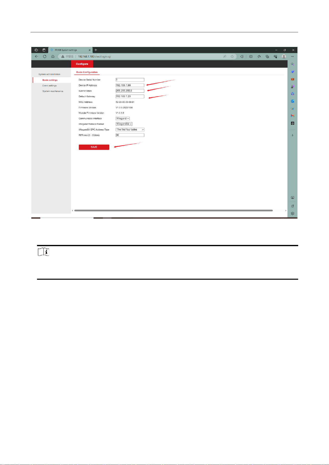
3.2.1 Network configuration
Users need to configure the IP address, subnet mask and gateway of the reader according to their
current network status. For example, configure the reader's network parameters as IP, subnet
mask and gateway as 192.168.1.99, 255.255.255.0, 192.168.1.20 respectively:
UHF Card Reader User Manual
10
Figure 3-4 Network configuration
Note
If you have changed your IP address, you will not be able to access the web pages with the
original IP address, please enter the new IP address in your browser address.
3.2.2 Working mode
The card reader has several modes of operation. In Enet mode the reader can act as a server or a
client. In Wiegand mode the reader can support Wiegand 26 or Wiegand 34 protocols.
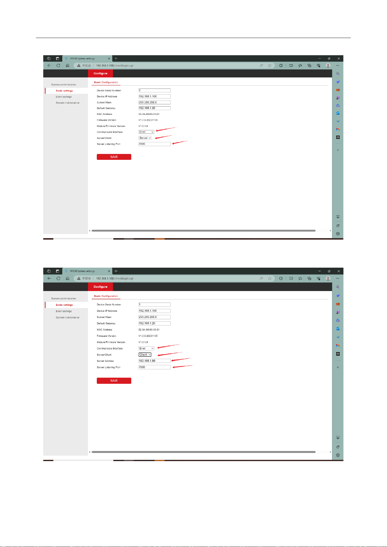
Enet mode:
In this mode, the reader can be reconfigured to either server mode or client mode. The specific
configuration mode depends on customer requirements.
UHF Card Reader User Manual
11
Figure 3-5 Enet server configuration
Figure 3-6 Enet client configuration

UHF Card Reader User Manual
12
Note
The reader works as the server mode. The default port is 7880. You can change it. If the reader
works as the client, you need to configure the IP address and port number of the server. For
example, if the IP address of the server is set to 192.168.1.99, the reader automatically connects
to the server after the server restarts.
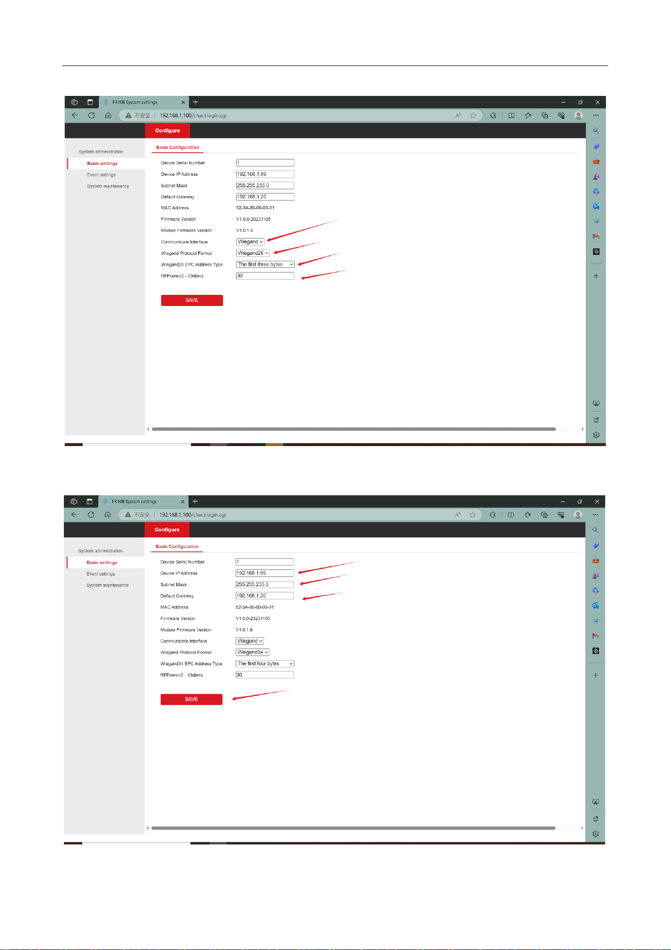
Wiegand mode:
When the working mode is Wiegand, there are two Wiegand protocols to choose from, Wiegand
26 and Wiegand 34. In addition, the user can configure the starting position of the EPC to be
reported and the RF power used for the inventory tags, the configuration steps are as follows:
1. select Wiegand as the communication mode
2. select Wiegand 26 or Wiegand 34 for the Wiegand protocol format as required
3. Wiegand EPC address type according to the need to select the first three / four bytes, the last
three / four bytes, as well as customized address offsets
4. Configure the RF power, click Save to wait for the device to reboot after the selection is
completed.
5. Select Wiegand communication mode, the device will automatically turn on the repeat Tag
filtering enable without any filtering conditions, the filtering interval is 1000ms, users can modify
the Tag filtering function according to their own needs.
6. Log in to the webpage, select the event setting interface, open the periodic time trigger event in
the inventory trigger event, configure the inventory time and interval according to your needs, and
click save after configuration.
UHF Card Reader User Manual
13
Figure 3-7 Wiegand 26 mode
UHF Card Reader User Manual
14
Figure 3-8 Wiegand 34 mode
The Wiegand 34 protocol format is reported as 4 bytes in length and the Wiegand 26 protocol
format is reported as 3 bytes in length.
Note
Wiegand mode EPC length needs to meet the Wiegand protocol data length. Wiegand 26 mode
EPC length needs to meet at least three bytes, if you choose to customize the address offset,
then the Tag EPC length needs to meet at least (address offset starting position (unit byte) +
three bytes of length) and above. For example: custom address offset starting position is 4, then
the EPC length to meet at least (4 + 3 = 7) bytes. Wiegand 34 protocol is similar.
Figure 3-9 The device automatically enables repeat label filtering
UHF Card Reader User Manual
15
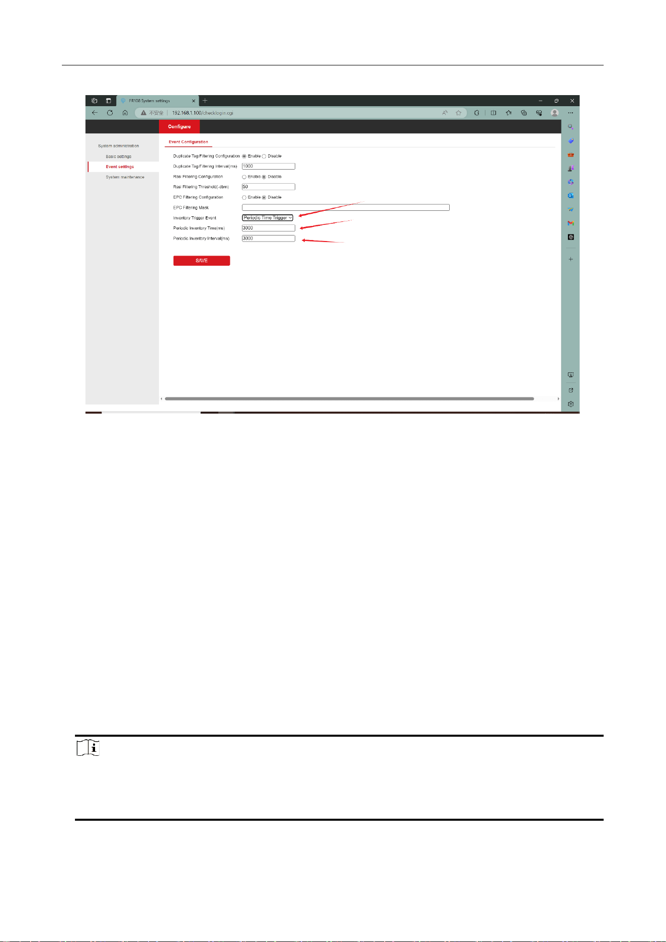
Figure 3-10 Configure device inventory trigger events
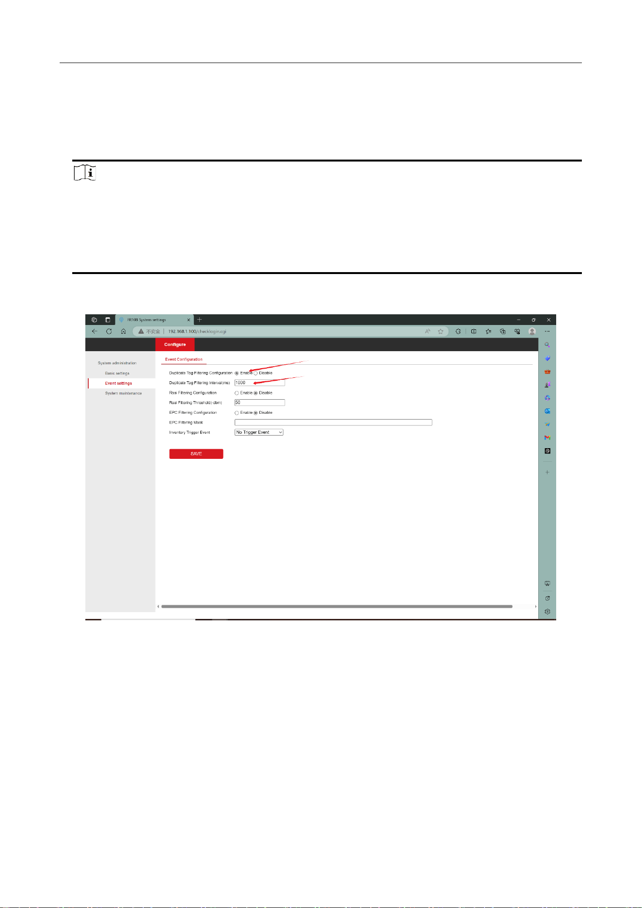
3.2.3 Event configuration
The event setting interface includes device label filtering, device inventory triggered events, click
save after the configuration is complete, the configuration will take effect immediately the device
will not reboot.
Tag Filtering Methods
Inventoried Tag can be filtered according to different filtering methods, by three filtering methods
can be configured:
Repeat Tag filtering: the same Tag is reported only once within the filtering time range.
Mask filtering: select the Tags with matching masks at the beginning of the EPC and filter out the
unmatched Tags.
RSSI value filtering: you can filter the tags according to the signal sensitivity of the read tags, and
filter out the tags with poor signal value.
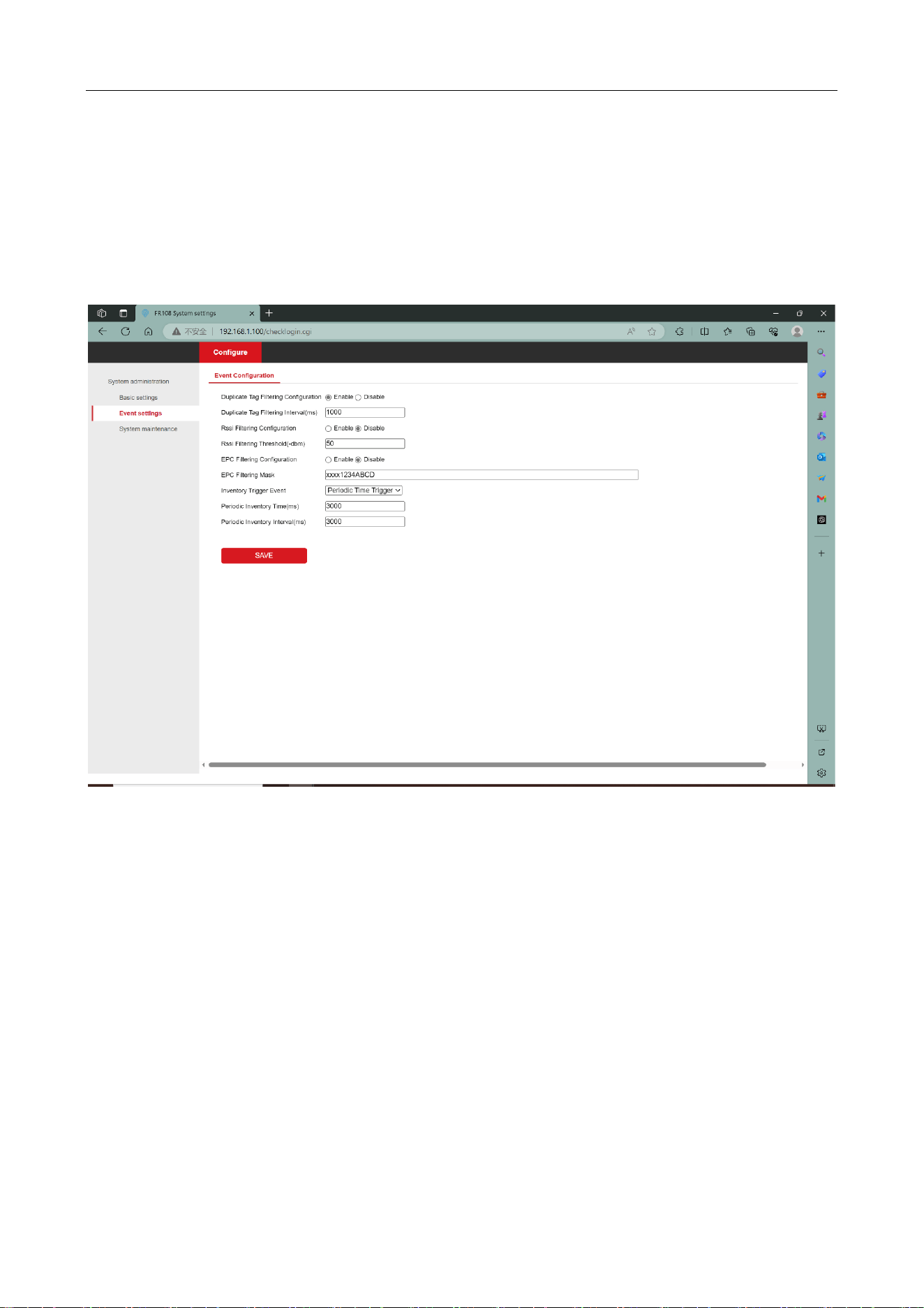
Note
Mask input for example: XXXX1234ABCD XXXX on behalf of the first two bytes of the EPC any
content matches, followed by 1234ABCD need to be labeled EPC 3rd to 6th byte content meets
the 1234ABCD to match.
UHF Card Reader User Manual
16
Inventory trigger event:
Once the event is established, the reader is powered on automatically inventory tags according to
the event. Cyclic event trigger event function for the device after powering up the automatic
inventory for a period of time after a period of hibernation and then enter the inventory mode,
and so on and so forth. The inventory time is determined by the periodic inventory time,
dormancy time is determined by the periodic inventory interval
Figure 3-11 Event configuration
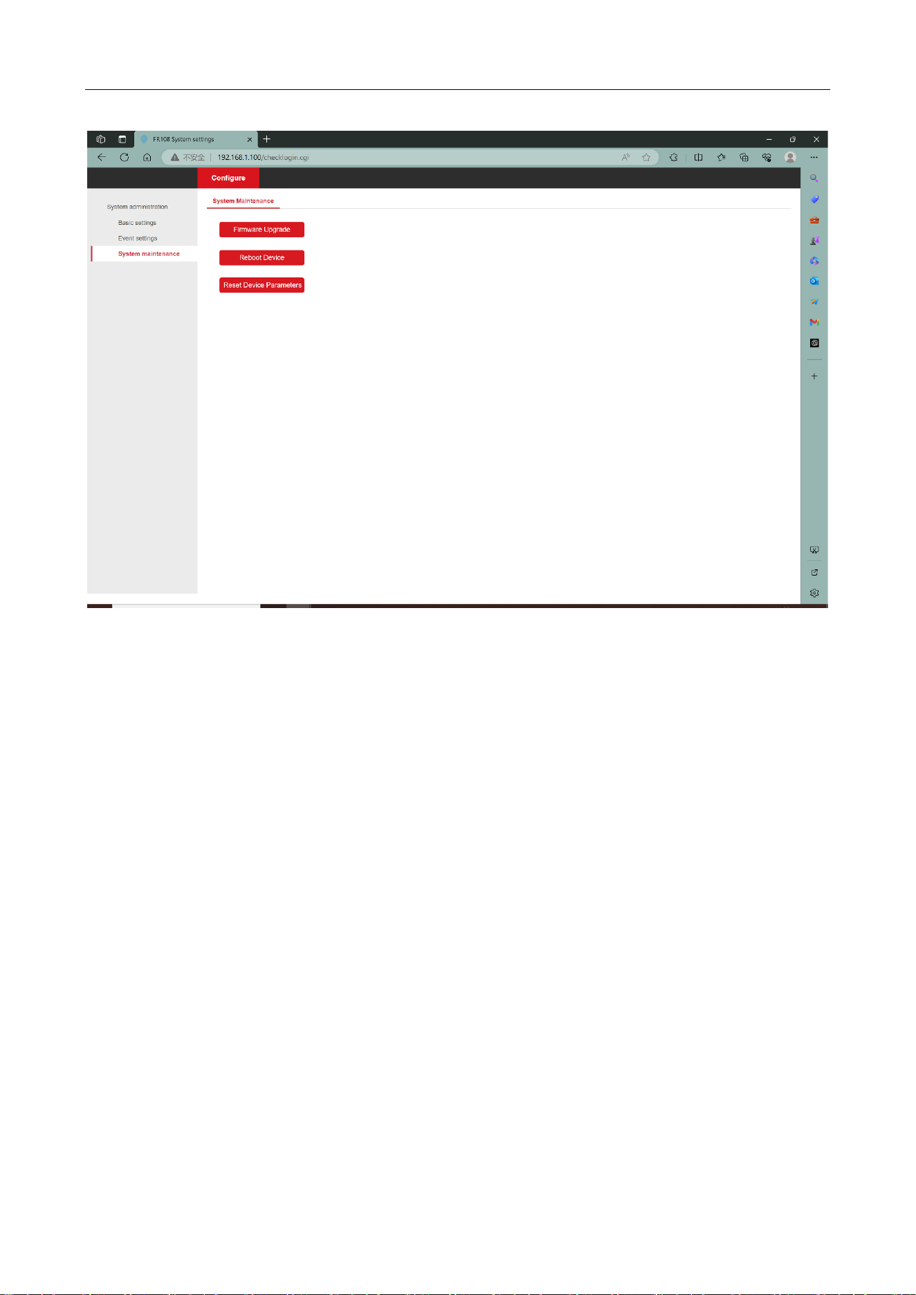
3.2.4 System maintenance
System maintenance interface contains firmware upgrade, restart the device, restore the device
parameters and other functions, these functions have a greater impact on the device, in order to
prevent misuse of the click will be prompted to confirm or not, after confirming that there is no
error, click OK.
Firmware upgrade:Updating the device firmware version.
Reboot device: device restart.
Reset Device Parameters: Restore the device parameter information to the default factory
state.
UHF Card Reader User Manual
17
Figure 3-12 System maintenance