Loading ...
Loading ...
Loading ...
Getting Started
R&S
®
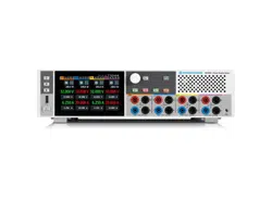
NGP800
24User Manual 5601.5610.02 ─ 04
For 32 V models, each output is capable to source 200 W of power at 0 V to 32 V and
maximum current of 20 A.
For 64 V models, each output is capable to source 200 W of power at 0 V to 64 V and
maximum current of 10A.
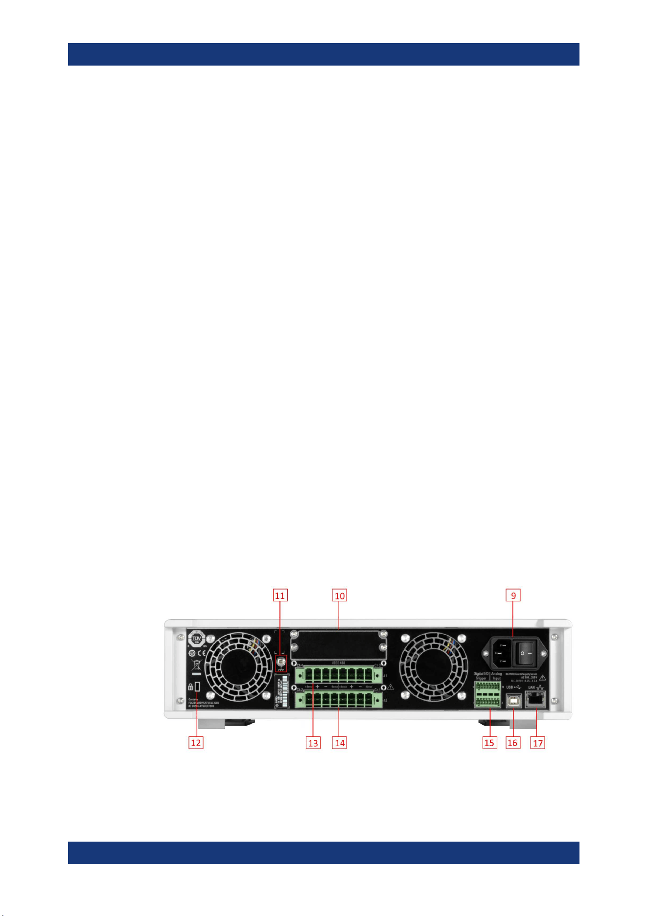
Chassis ground terminal (5)
A 4 mm socket is provided for the user to connect to earth ground through the instru-
ment ground/chassis.
Standby button (6)
The [Power] key toggles the instrument between standby state and normal state. In
standby state, the key is illuminated in red and the instrument internal circuits are oper-
ated in powered down state. In normal state, all the internal modules are powered up
and the instrument will startup to operate normally. The LED illumination is turned off in
this state.
USB connector (7)
USB Type-A connector is provided for connecting a USB flash drive to perform soft-
ware update, store logging data or screen captures. It can also be used for an external
USB mouse connector.
Menu control keys (8)
The menu control keys allow you to access the home window, main menu window and
user button key in the instrument.
For a detailed description on menu control keys, see section "Menu Controls" in the
User Manual.
4.2.1.2 Rear Panel
Figure 4-3 shows the rear panel of the R&S NGP800 power supply with its connectors.
Figure 4-3: Rear panel of R&S
NGP800 power supply
Instrument Tour
Loading ...
Loading ...
Loading ...