Home
Bookmarks
Home
Marvel
Marvel MO24RAS1RS User Manual
Page 117
Marvel MO24RAS1RS 24 Inch Outdoor Built-In Compact Refrigerator with 5.3 cu. ft. Capacity, 2 Stainless Steel Shelves, Right Hinge, with Door Lock, Energy Star Certified, Dynamic Cooling Technology, FreshFlo Shelves, Prime Controls, Close Door Assist
User Manual - Page 117
For MO24RAS1RS.
PDF File Manual
,
288 pages
,
Read Online
|
Download pdf file
Cover Page
Section 0 (Table of Contents)
Section 1 (Introduction)
1.1 Unit Specifications
1.2 Serial Nameplate
1.3 Servicing
1.4 Basic Refrigeration Tools
1.5 Basic Installation
1.6 Electrical Requirements
Section 2 (Sealed System)
2.1 Introduction
2.2 Low Side Leaks
2.3 High Side Leaks
2.4 Restricted Capillary Tube
2.5 Access/Process Valves
2.6 Evaporator Frost Pattern
2.7 Measuring Evaporator Temperature
2.8 Re-charging
2.9 Temperature / Pressure Chart
Section 3 (Sealed System Components)
3.1. Toe Grill Removal
3.2: Warnings and Cautions
3.3 Accessing the Mechanical Compartment
3.4: Compressor
3.4.1: Check Compressor Winding Resistance
3.4.2: Remove the Compressor
3.4.3: Install a New Compressor
3.5: Condenser
3.5.1: Remove the Condenser
3.5.2: Install a New Condenser
3.6: Evaporator
3.6.1: Remove the Evaporator
3.6.2: Install a New Evaporator
Section 4 (Electrical Component Access)
4.1: Condenser Fan
4.1.1: Fan Assembly Removal
4.1.2: Condenser Fan Replacement
4.1.3: Fan Assembly Installation
4.1.4: Condenser Fan Blade Spacing
4.2: Evaporator Fan Access
4.3: Thermistor Locations
Section 5 (User Interface Display)
5.1 Model Variations
5.3 User Interface Navigation â Beverage Centers
5.4 User Interface Navigation â Wine Coolers
5.5 User Interface Navigation â Refrigerated Drawers
5.5 User Interface Navigation â Beer Dispenser
Section 6 (Control System)
6.1 User Interface Display
6.1.1 Removing the User Interface Display
6.1.2 Installing a new User Interface Display
6.2: Main Control Board
6.2.1: Control Board Replacement
6.2.2: Removing the Programming / Data cable
6.2.3: Re-Installing the Programming / Data cable
6.2.4: Control Board Installation
6.3: Cabinet and Defrost Thermistors
6.3.1 Thermistor (Sensor)
6.3.2: Check the Thermistor
6.3.3: Removing the Cabinet Thermistor
6.3.4: Installing the Cabinet Thermistor
6.3.5: Removing the Defrost Thermistor
6.3.6: Installing the Defrost Thermistor
6.3.7: Thermistor Harness Identification
6.4: Temperature Resistance Chart
6.5: Door Sensor
6.5.1: Door Sensor Removal
6.5.2: Door Sensor Replacement
6.6: Defrost Modes
6.6.1: Defrost Characteristics
6.6.2 Auto Defrost
6.6.3 Manual Defrost
6.7 Error Codes
Section 7 (Lights, Doors, Drawer, and Hinges)
7.1 LED Lighting
7.1.1: Replacing the LED Light
7.2: Cabinet Door
7.2.1 Door Removal
7.2.2 Bottom Door Closer
7.3: Refrigerated Drawers
7.4: Doors / Drawers Handle Adjustment
7.5: Door Alignment /Adjustment
7.6: Gasket Adjust / Replace
7.7 Articulating Hinges
Section 8 (Evaporator Compartment Access)
8.1: Beverage Centers
8.2: Wine Coolers
8.3: Refrigerated Drawers
8.4: Evaporator Cover Drip Edge
Section 9 (Wiring Diagrams)
9.1 Block Diagram of Main Power Board
9.2 Schematic Diagram
9.3 Main Power Board Identification
Section 10 (Power On reset Mode)
10.1: Auto Self-Test
10.2: Manual Auto Test Mode
10.3: Control Types
Section 11 (Quick Reference Troubleshooting)
Section 12 (Diagnostic Flow Charts)
Section 13 (Gathering Service Data)
13.1: PROGRAM PORT
13.1.1: SERVICE DATA RETRIEVAL
13.1.2: Service Data Port Location
13.1.3: Onboard Diagnostics
Section 14 (Beer Dispenser)
14.1: Interior mechanical / electrical components
14.2: Main Control Board Access
14.3: Machine Compartment
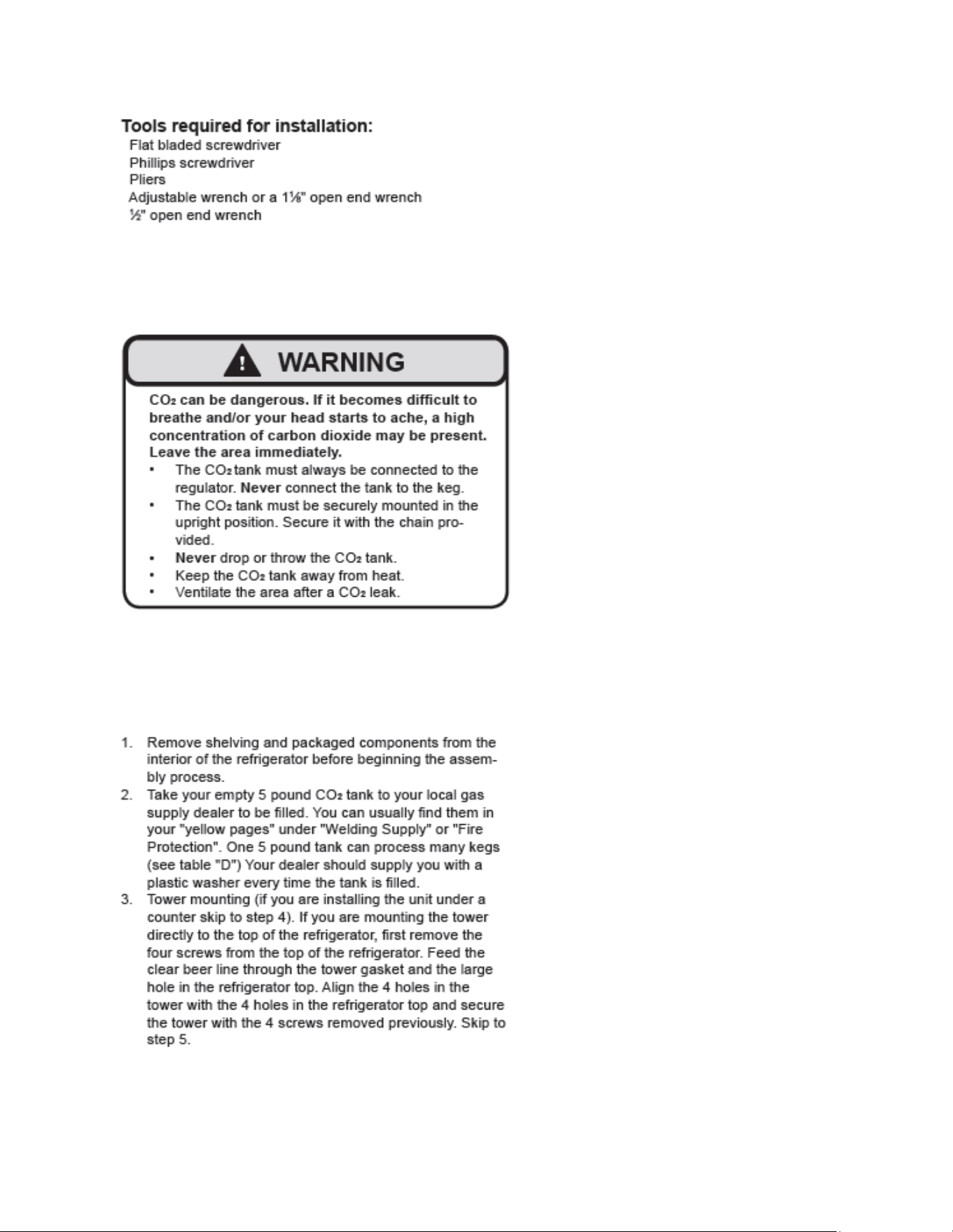
14.4: Excerpt from Owners / Maintenance Instruction Guide
Section 15 (Dual Zones)
15.1: User Interface Control
15.2: Operation
15.3: Characteristics
15.4: Dual Zone Compartment Air Flow
15.5: Divider Removal
15.6: Damper Operation
15.7: Compartment Fan Operation
15.8: Heater Operation
15.9: Thermistors
15.10: Evaporator Access
15.11: Interior LEDâs
15.12: Defrost / Drip Time
15.13: Refrigeration and Mechanical
Section 16 (Refrigerator Freezers)
16.1: User Interface Control
16.2: Operation
16.3: Characteristics
16.4: Damper Operation
16.5: Fan Operation
16.6: Thermistors
16.7: Refrigeration and Mechanical
16.8: Evaporator
16.9: Defrost
16.10: ACCESS TO THE DEFROST COMPONENTS
16.11: RFI (Refrigerator Freezer- Ice Maker)
Section 17 (Outdoor Models)
17.1: Operation
17.2: Characteristics / Differences
17.3: Fans
17.4: Thermistors
17.5: Control Type
17.6 : Control Functions
17.7: Control Locations per Model
17.8: Machine Compartment
17.9: Main Power Board Access
17.10: Display Access and Replacement
17.11: Thermistor Resistance
17.12: Wiring Diagram
17.13: Generic Trouble shooting Charts
17.14: Refrigeration and Mechanical
Section 18 (Prime Control)
18.1: Control Type
18.2: Control Functions
18.3: Fans
18.4: Thermistors
18.5: Machine Compartment
18.6: Thermistor Resistance
18.7: Wiring Diagram
18.8: Generic Trouble shooting Chart
18.9: Refrigeration and Mechanical
Section 19 (Clear Ice Machines)
19.1 Control Operation
19.2: Control System
19.3: Interior Features
19.4: Machine Compartment Components
19.5: Diagnostic Test Modes
19.6: Diagnostic Charts
19.7: Trouble Shooting
19.8: VAC Wiring Diagram and Schematics
19.9: Specifications:
19.10: Production and Harvest Guidelines
Section 20 (Service Kits / Bulletins)
20.1: Service Bulletin # 41013862Mullion Condensation on Refrigerated Drawers
20.2: SERVICE BULLETIN # 41013861EVAPORATOR REPLACEMENT KIT
20.3: SERVICE BULLETIN # 41013995 Rev CContact between the Door and Door Sensor
20.4: SERVICE BULLETIN # 41014167Slotted Condenser Shroud
20.5: SERVICE BULLETIN # 41014168Showroom Mode Alarm
20.6: SERVICE BULLETIN # 41014169Evaporator / Heat Exchanger Replacement(RF and RFI Models ONLY)
20.7: SERVICE BULLETIN # 41014241Shelf Shim Kit
20.8: Service Bulletin # 41014242Miscellaneous Control Communication Errors
20.9: Service Bulletin # 41014243Replacement of MP Door Skins
Section 21 (Customer Service Contact Information)
Section 22 (Notes)
Back Page
Page 117/288
Page 1
Page 2
Page 3
Page 4
Page 5
Page 6
Page 7
Page 8
Page 9
Page 10
Page 11
Page 12
Page 13
Page 14
Page 15
Page 16
Page 17
Page 18
Page 19
Page 20
Page 21
Page 22
Page 23
Page 24
Page 25
Page 26
Page 27
Page 28
Page 29
Page 30
Page 31
Page 32
Page 33
Page 34
Page 35
Page 36
Page 37
Page 38
Page 39
Page 40
Page 41
Page 42
Page 43
Page 44
Page 45
Page 46
Page 47
Page 48
Page 49
Page 50
Page 51
Page 52
Page 53
Page 54
Page 55
Page 56
Page 57
Page 58
Page 59
Page 60
Page 61
Page 62
Page 63
Page 64
Page 65
Page 66
Page 67
Page 68
Page 69
Page 70
Page 71
Page 72
Page 73
Page 74
Page 75
Page 76
Page 77
Page 78
Page 79
Page 80
Page 81
Page 82
Page 83
Page 84
Page 85
Page 86
Page 87
Page 88
Page 89
Page 90
Page 91
Page 92
Page 93
Page 94
Page 95
Page 96
Page 97
Page 98
Page 99
Page 100
Page 101
Page 102
Page 103
Page 104
Page 105
Page 106
Page 107
Page 108
Page 109
Page 110
Page 111
Page 112
Page 113
Page 114
Page 115
Page 116
Page 117
Page 118
Page 119
Page 120
Page 121
Page 122
Page 123
Page 124
Page 125
Page 126
Page 127
Page 128
Page 129
Page 130
Page 131
Page 132
Page 133
Page 134
Page 135
Page 136
Page 137
Page 138
Page 139
Page 140
Page 141
Page 142
Page 143
Page 144
Page 145
Page 146
Page 147
Page 148
Page 149
Page 150
Page 151
Page 152
Page 153
Page 154
Page 155
Page 156
Page 157
Page 158
Page 159
Page 160
Page 161
Page 162
Page 163
Page 164
Page 165
Page 166
Page 167
Page 168
Page 169
Page 170
Page 171
Page 172
Page 173
Page 174
Page 175
Page 176
Page 177
Page 178
Page 179
Page 180
Page 181
Page 182
Page 183
Page 184
Page 185
Page 186
Page 187
Page 188
Page 189
Page 190
Page 191
Page 192
Page 193
Page 194
Page 195
Page 196
Page 197
Page 198
Page 199
Page 200
Page 201
Page 202
Page 203
Page 204
Page 205
Page 206
Page 207
Page 208
Page 209
Page 210
Page 211
Page 212
Page 213
Page 214
Page 215
Page 216
Page 217
Page 218
Page 219
Page 220
Page 221
Page 222
Page 223
Page 224
Page 225
Page 226
Page 227
Page 228
Page 229
Page 230
Page 231
Page 232
Page 233
Page 234
Page 235
Page 236
Page 237
Page 238
Page 239
Page 240
Page 241
Page 242
Page 243
Page 244
Page 245
Page 246
Page 247
Page 248
Page 249
Page 250
Page 251
Page 252
Page 253
Page 254
Page 255
Page 256
Page 257
Page 258
Page 259
Page 260
Page 261
Page 262
Page 263
Page 264
Page 265
Page 266
Page 267
Page 268
Page 269
Page 270
Page 271
Page 272
Page 273
Page 274
Page 275
Page 276
Page 277
Page 278
Page 279
Page 280
Page 281
Page 282
Page 283
Page 284
Page 285
Page 286
Page 287
Page 288
Contents
Table of Contents
Search
Previous
Next
Troubleshooting
Bookmarks
Loading ...
Loading ...
Loading ...
112
Loading ...
Loading ...
Loading ...
File type: PDF
File name: 93634174_mo24ras1rs.pdf
File size: 22.06 MB
File Language: English
Pages: 288
Author: Marvel
File created: 2015-09-02
Published: 2024-02-18
Updated: 2024-02-18
Download File
Table of Contents
×
Cover Page
1
Section 0 (Table of Contents)
3
Section 1 (Introduction)
6
1.1 Unit Specifications
6
1.2 Serial Nameplate
7
1.3 Servicing
8
1.4 Basic Refrigeration Tools
8
1.5 Basic Installation
9
1.6 Electrical Requirements
9
Section 2 (Sealed System)
10
2.1 Introduction
10
2.2 Low Side Leaks
10
2.3 High Side Leaks
11
2.4 Restricted Capillary Tube
11
2.5 Access/Process Valves
11
2.6 Evaporator Frost Pattern
11
2.7 Measuring Evaporator Temperature
13
2.8 Re-charging
13
2.9 Temperature / Pressure Chart
16
Section 3 (Sealed System Components)
17
3.1. Toe Grill Removal
17
3.2: Warnings and Cautions
19
3.3 Accessing the Mechanical Compartment
19
3.4: Compressor
22
3.4.1: Check Compressor Winding Resistance
22
3.4.2: Remove the Compressor
23
3.4.3: Install a New Compressor
23
3.5: Condenser
23
3.5.1: Remove the Condenser
24
3.5.2: Install a New Condenser
25
3.6: Evaporator
26
3.6.1: Remove the Evaporator
26
3.6.2: Install a New Evaporator
28
Section 4 (Electrical Component Access)
29
4.1: Condenser Fan
29
4.1.1: Fan Assembly Removal
29
4.1.2: Condenser Fan Replacement
31
4.1.3: Fan Assembly Installation
31
4.1.4: Condenser Fan Blade Spacing
32
4.2: Evaporator Fan Access
33
4.3: Thermistor Locations
36
Section 5 (User Interface Display)
38
5.1 Model Variations
38
5.3 User Interface Navigation â Beverage Centers
39
5.4 User Interface Navigation â Wine Coolers
43
5.5 User Interface Navigation â Refrigerated Drawers
47
5.5 User Interface Navigation â Beer Dispenser
50
Section 6 (Control System)
53
6.1 User Interface Display
53
6.1.1 Removing the User Interface Display
53
6.1.2 Installing a new User Interface Display
55
6.2: Main Control Board
56
6.2.1: Control Board Replacement
56
6.2.2: Removing the Programming / Data cable
60
6.2.3: Re-Installing the Programming / Data cable
60
6.2.4: Control Board Installation
61
6.3: Cabinet and Defrost Thermistors
61
6.3.1 Thermistor (Sensor)
61
6.3.2: Check the Thermistor
61
6.3.3: Removing the Cabinet Thermistor
62
6.3.4: Installing the Cabinet Thermistor
62
6.3.5: Removing the Defrost Thermistor
62
6.3.6: Installing the Defrost Thermistor
62
6.3.7: Thermistor Harness Identification
64
6.4: Temperature Resistance Chart
65
6.5: Door Sensor
66
6.5.1: Door Sensor Removal
67
6.5.2: Door Sensor Replacement
68
6.6: Defrost Modes
68
6.6.1: Defrost Characteristics
68
6.6.2 Auto Defrost
69
6.6.3 Manual Defrost
70
6.7 Error Codes
70
Section 7 (Lights, Doors, Drawer, and Hinges)
71
7.1 LED Lighting
71
7.1.1: Replacing the LED Light
71
7.2: Cabinet Door
72
7.2.1 Door Removal
72
7.2.2 Bottom Door Closer
74
7.3: Refrigerated Drawers
75
7.4: Doors / Drawers Handle Adjustment
77
7.5: Door Alignment /Adjustment
79
7.6: Gasket Adjust / Replace
79
7.7 Articulating Hinges
80
Section 8 (Evaporator Compartment Access)
82
8.1: Beverage Centers
82
8.2: Wine Coolers
84
8.3: Refrigerated Drawers
84
8.4: Evaporator Cover Drip Edge
87
Section 9 (Wiring Diagrams)
88
9.1 Block Diagram of Main Power Board
88
9.2 Schematic Diagram
89
9.3 Main Power Board Identification
92
Section 10 (Power On reset Mode)
94
10.1: Auto Self-Test
94
10.2: Manual Auto Test Mode
94
10.3: Control Types
94
Section 11 (Quick Reference Troubleshooting)
96
Section 12 (Diagnostic Flow Charts)
97
Section 13 (Gathering Service Data)
104
13.1: PROGRAM PORT
104
13.1.1: SERVICE DATA RETRIEVAL
104
13.1.2: Service Data Port Location
105
13.1.3: Onboard Diagnostics
106
Section 14 (Beer Dispenser)
108
14.1: Interior mechanical / electrical components
108
14.2: Main Control Board Access
111
14.3: Machine Compartment
113
14.4: Excerpt from Owners / Maintenance Instruction Guide
115
Section 15 (Dual Zones)
122
15.1: User Interface Control
122
15.2: Operation
122
15.3: Characteristics
123
15.4: Dual Zone Compartment Air Flow
124
15.5: Divider Removal
125
15.6: Damper Operation
127
15.7: Compartment Fan Operation
130
15.8: Heater Operation
131
15.9: Thermistors
132
15.10: Evaporator Access
133
15.11: Interior LEDâs
134
15.12: Defrost / Drip Time
134
15.13: Refrigeration and Mechanical
136
Section 16 (Refrigerator Freezers)
137
16.1: User Interface Control
137
16.2: Operation
137
16.3: Characteristics
138
16.4: Damper Operation
139
16.5: Fan Operation
141
16.6: Thermistors
143
16.7: Refrigeration and Mechanical
144
16.8: Evaporator
145
16.9: Defrost
146
16.10: ACCESS TO THE DEFROST COMPONENTS
147
16.11: RFI (Refrigerator Freezer- Ice Maker)
150
Section 17 (Outdoor Models)
161
17.1: Operation
161
17.2: Characteristics / Differences
161
17.3: Fans
161
17.4: Thermistors
162
17.5: Control Type
163
17.6 : Control Functions
163
17.7: Control Locations per Model
164
17.8: Machine Compartment
165
17.9: Main Power Board Access
165
17.10: Display Access and Replacement
166
17.11: Thermistor Resistance
171
17.12: Wiring Diagram
171
17.13: Generic Trouble shooting Charts
172
17.14: Refrigeration and Mechanical
173
Section 18 (Prime Control)
174
18.1: Control Type
174
18.2: Control Functions
176
18.3: Fans
177
18.4: Thermistors
177
18.5: Machine Compartment
178
18.6: Thermistor Resistance
179
18.7: Wiring Diagram
179
18.8: Generic Trouble shooting Chart
180
18.9: Refrigeration and Mechanical
180
Section 19 (Clear Ice Machines)
181
19.1 Control Operation
181
19.2: Control System
185
19.3: Interior Features
203
19.4: Machine Compartment Components
211
19.5: Diagnostic Test Modes
234
19.6: Diagnostic Charts
236
19.7: Trouble Shooting
242
19.8: VAC Wiring Diagram and Schematics
245
19.9: Specifications:
247
19.10: Production and Harvest Guidelines
248
Section 20 (Service Kits / Bulletins)
250
20.1: Service Bulletin # 41013862Mullion Condensation on Refrigerated Drawers
250
20.2: SERVICE BULLETIN # 41013861EVAPORATOR REPLACEMENT KIT
260
20.3: SERVICE BULLETIN # 41013995 Rev CContact between the Door and Door Sensor
263
20.4: SERVICE BULLETIN # 41014167Slotted Condenser Shroud
267
20.5: SERVICE BULLETIN # 41014168Showroom Mode Alarm
268
20.6: SERVICE BULLETIN # 41014169Evaporator / Heat Exchanger Replacement(RF and RFI Models ONLY)
270
20.7: SERVICE BULLETIN # 41014241Shelf Shim Kit
277
20.8: Service Bulletin # 41014242Miscellaneous Control Communication Errors
281
20.9: Service Bulletin # 41014243Replacement of MP Door Skins
282
Section 21 (Customer Service Contact Information)
285
Section 22 (Notes)
286
Back Page
288
Search:
×
Search