EN
USER AND SAFETY GUIDE
2 CIRCUIT WI-FI RELAY SWITCH WITH
POWER MEASUREMENT AND COVER
CONTROL CAPABILITY
Read before use
This document contains important technical and safety in-
formation about the device, its safety use and installation.
⚠CAUTION! Before beginning the installation, please read
this guide and any other documents accompanying the device
carefully and completely. Failure to follow the installation pro-
cedures could lead to malfunction, danger to your health and
life, violation of the law or refusal of legal and/or commercial
guarantee (if any). Allterco Robotics EOOD is not responsible
for any loss or damage in case of incorrect installation or im-
proper operation of this device due to failure of following the
user and safety instructions in this guide.
Product Introduction
Shelly® is a line of innovative microprocessor-managed
devices, which allow remote control of electric appliances
through a mobile phone, tablet, PC, or home automation
system. Shelly® devices can work standalone in a local Wi-Fi
network or they can also be operated through cloud home
automation services. Shelly Cloud is such a service that can
be accessed using either Android or iOS mobile application,
or with any internet browser at https://home.shelly.cloud/.
Shelly® devices can be accessed, controlled and monitored
remotely from any place where the User has internet connec-
tivity, as long as the devices are connected to a Wi-Fi router
and the Internet. Shelly® devices have embedded Web Inter-
face accessible at http://192.168.33.1 in the Wi Fi network,
created by the device in Access Point mode, or at the URL
address of the device in the Wi-Fi network it is connected to.
The embedded Web Interface can be used to monitor and
control the device, as well as adjust its settings.
Shelly® devices can communicate directly with other Wi-Fi
devices through HTTP protocol. An API is provided by Allter-
co Robotics EOOD. For more information, please visit:
https://shelly-api-docs.shelly.cloud/#shelly-family-overview
.
Shelly® devices are delivered with factory-installed rmware.
If rmware updates are necessary to keep the devices in con-
formity, including security updates, Allterco Robotics EOOD
will provide the updates free of charge through the device
embedded Web Interface or Shelly Mobile Application, where
the information about the current rmware version is avail-
able. The choice to install or not the Device rmware updates
is User’s sole responsibility. Allterco Robotics EOOD shall not
be liable for any lack of conformity of the Device caused by
failure of the User to install the provided updates in a timely
manner.
Shelly® Plus line offers PM products capable of real-time
precise power measurement.
Control your home with your voice
Shelly® devices are compatible with Amazon Alexa and Goo-
gle Home supported functionalities. Please see our step-by-
step guide on: https://shelly.cloud/support/compatibility/.
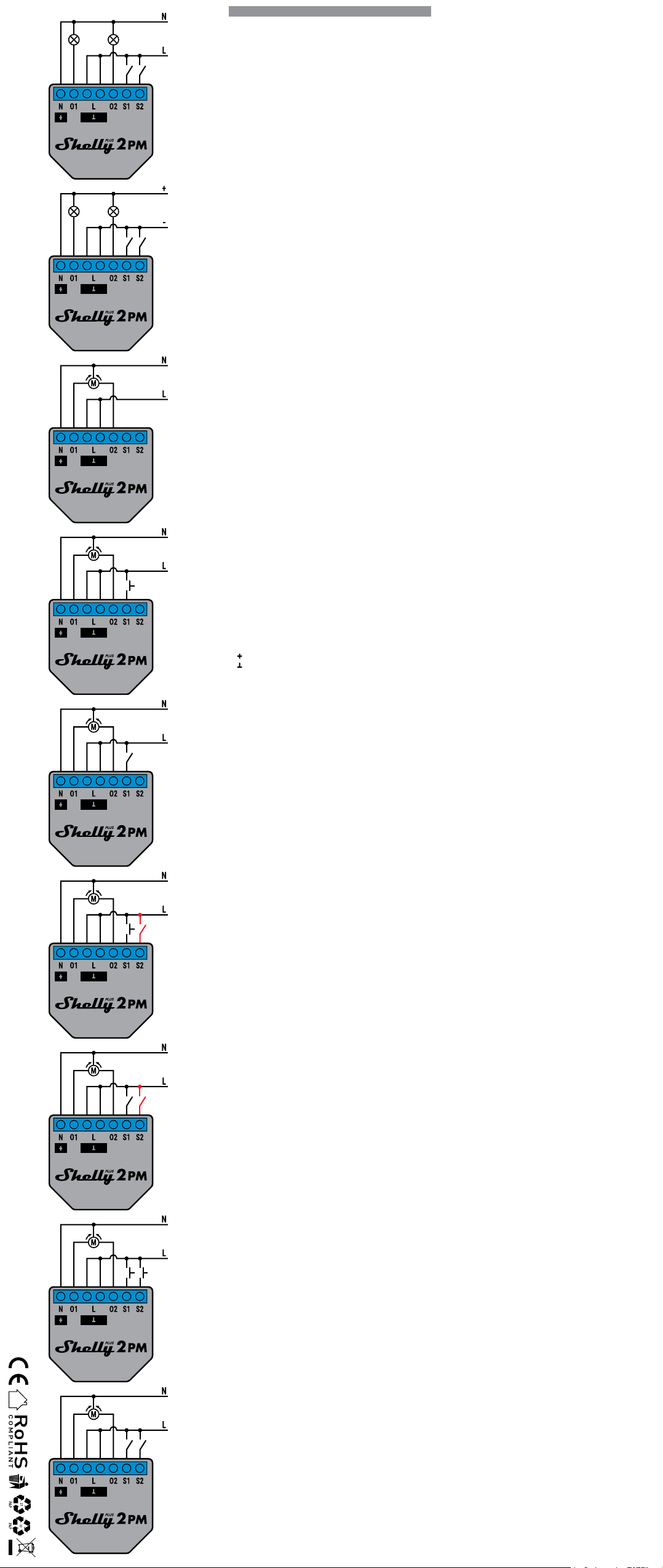
Schematics
See the schematics at the begining of the user guide.
Legend
Device terminals:
• O1: Load circuit 1 output terminal
• O2: Load circuit 2 output terminal
• S1: Switch (controlling O1) input terminal
• S2: Switch (controlling O2) input terminal
• L: Live (110-240 VAC) terminals
• N: Neutral terminal
• : 24 VDC positive terminal
• : 24 VDC negative terminal
Cables:
• N: Neutral cable
• L: Live (110-240 VAC) cable
• +: 24 VDC positive cable
• -: 24 VDC negative cable
Installation Instructions
Shelly® Plus 2PM (the Device) can control 2 electrical cir-
cuits, including a bi-directional AC motor. Each circuit can be
loaded up to 10 A (16 A total for both circuits) and its power
consumption can be measured individually (AC only). It can
be retrotted into a standard in-wall console, behind power
sockets and light switches or other places with limited space.
⚠CAUTION! Danger of electrocution. Mounting/installation
of the Device to the power grid has to be performed with cau-
tion, by a qualied electrician.
⚠CAUTION! Danger of electrocution. Every change in the
connections has to be done after ensuring there is no voltage
present at the Device terminals.
⚠CAUTION! Use the Device only with a power grid and ap-
pliances which comply with all applicable regulations. A short
circuit in the power grid or any appliance connected to the De-
vice may damage the Device.
⚠CAUTION! Do not connect the Device to appliances ex-
ceeding the given max load!
⚠CAUTION! Connect the Device only in the way shown in
these instructions. Any other method could cause damage
and/or injury.
⚠CAUTION! Do not install the device at a place that is pos-
sible to get wet.
⚠RECOMMENDATION Connect the Device using solid sin-
gle-core cables with increased insulation heat resistance not
less than PVC T105°C.
Before starting installing/mounting the Device, wire check
that the breakers are turned off and there is no voltage on
their terminals. This can be done with a phase meter or mul-
timeter. When you are sure that there is no voltage, you can
proceed to connecting the cables.
If you want to use the Device as a relay switch to control 2
load circuits, connect the Device as shown on Fig. 1 for AC
circuits and on Fig. 2 for DC circuits.
⚠CAUTION! Use the same power supply for the two load
circuits and the Device.
For AC circuits connect both L terminals to the Live cable
and the N terminal to the Neutral cable. Connect the rst load
circuits to the O1 terminal and the Neutral cable. Connect
the second load circuits to the O2 terminal and the Neutral
cable. Connect the rst switch to the S1 terminal and the Live
cable. Connect the second switch to the S2 terminal and the
Live cable.
For DC circuits connect both L terminals to the Negative
cable and the N terminal to the Positive cable. Connect the
rst load circuits to the O1 terminal and the Positive cable.
Connect the second load circuits to the O2 terminal and the
Positive cable. Connect the rst switch to the S1 terminal and
the Negative cable. Connect the second switch to the S2 ter-
minal and the Negative cable.
⚠RECOMMENDATION: For inductive appliances that cause
voltage spikes during switching on/off, such as electrical
motors, fans, vacuum cleaners and similar ones, RC snubber
(0.1µF / 100Ω / 1/2W / 600V AC) should be connected parallel
to the appliance.
The RC snubber can be purchased at
https://shop.shelly.cloud/rc-snubber-wi-smart-home-automation
As a cover controller Shelly® Plus 2PM can work in 3 modes:
detached, single input or dual input.
In detached mode, the Device can be controlled through its
WebUI and the App only. Even if buttons or switches are con-
nected to the Device, they will not be allowed to control the
motor rotation in detached mode.
If you want to use the Device in detached mode connect the
device as shown on Fig. 3: Connect both L terminals to the
Live cable and the N terminal to the Neutral cable. Connect
the common motor terminal/cable to the Neutral cable.
Connect motor direction terminals/cables to the O1 and O2
terminals.*
If you want to use the Device in single input mode connect
the device as shown on Fig. 4 for a button input or Fig. 5 for
a switch input. Connect both L terminals to the Live cable
and the N terminal to the Neutral cable. Connect the common
motor terminal/cable to the Neutral cable. Connect motor di-
rection terminals/cables to the O1 and O2 terminals*.
Connect the button or the switch to the S1 or the S2 terminal
and the Live cable.
If the input is congured as a button in the Device settings,
each button press cycles open, stop, close, stop...
If the input is congured as a switch, each switch toggle cy-
cles open, stop, close, stop...
In single input mode Shelly® Plus 2PM provides safety
switch functionality. To utilize it, connect the device as shown
on Fig. 6 for a button input or Fig. 7 for a switch input. Con-
nect both L terminals to the Live cable and the N terminal to
the Neutral cable. Connect the common motor terminal/ca-
ble to the Neutral cable. Connect motor direction terminals/
cables to the O1 and O2 terminals*.
Connect the controlling button or switch to the S1 terminal
and the Live cable. Connect the safety switch to the S2 termi-
nal and the Live cable.
DE
BENUTZER- UND
SICHERHEITSHANDBUCH
WI-FI-RELAISSCHALTER
MIT 2 SCHALTKREISEN,
LEISTUNGSMESSUNG UND
ABDECKUNGSSTEUERUNG
Vor Benutzung lesen
Dieses Dokument enthält wichtige technische und sicher-
heitstechnische Informationen über das Gerät und seine
sichere Verwendung und Installation.
⚠ACHTUNG! Bevor Sie mit der Installation beginnen, lesen
Sie bitte die Begleitdokumentation sorgfältig und vollständig
durch. Die Nichtbeachtung der empfohlenen Verfahren kann
zu Fehlfunktionen, Lebensgefahr oder Gesetzesverstößen
führen. Allterco Robotics EOOD haftet nicht für Verluste oder
Schäden im Falle einer falschen Installation oder Bedienung
dieses Geräts.
Produkt-Einführung
Shelly® ist eine Reihe innovativer, mikroprozessorgesteu-
erter Geräte, die die Fernsteuerung von Elektrogeräten über
ein Mobiltelefon, ein Tablet, einen PC oder ein Hausauto-
matisierungssystem ermöglichen. Shelly® Geräte können
eigenständig in einem lokalen Wi-Fi-Netzwerk arbeiten oder
sie können auch über Cloud-Dienste für die Hausautoma-
tion betrieben werden. Shelly Cloud ist ein solcher Dienst,
auf den entweder über eine Android- oder iOS-Mobilan-
wendung oder über einen beliebigen Internetbrowser unter
https://home.shelly.cloud/ zugegriffen werden kann. Shelly®
Geräte können von jedem Ort aus, an dem der Benutzer eine
Internetverbindung hat, angesprochen, gesteuert und über-
wacht werden, solange die Geräte mit einem Wi-Fi-Router und
dem Internet verbunden sind. Shelly® Geräte verfügen über
ein integriertes Web-Interface, das unter http://192.168.33.1
im Wi-Fi-Netzwerk zugänglich ist, das vom Gerät im Access
Point-Modus erstellt wird, oder unter der URL-Adresse des
Geräts im Wi-Fi-Netzwerk, mit dem es verbunden ist. Das
integrierte Web-Interface kann zur Überwachung und Steue-
rung des Geräts sowie zur Anpassung seiner Einstellungen
verwendet werden.
Shelly® Geräte können direkt mit anderen Wi-Fi-Geräten über
das HTTP-Protokoll kommunizieren. Eine API wird von Allter-
co Robotics EOOD bereitgestellt. Für weitere Informationen
besuchen Sie bitte:
https://shelly-api-docs.shelly.cloud/#shelly-family-overview
.
Shelly® Geräte werden mit werkseitig installierter Firmware
geliefert. Wenn Firmware-Updates erforderlich sind, um die
Geräte konform zu halten, einschließlich Sicherheitsupdates,
stellt Allterco Robotics EOOD die Updates kostenlos über die
in das Gerät eingebettete Webschnittstelle oder die Shelly
Mobile Application zur Verfügung, wo die Informationen über
die aktuelle Firmware-Version verfügbar sind. Die Entschei-
dung, die Firmware-Updates des Geräts zu installieren oder
nicht, liegt in der alleinigen Verantwortung des Benutzers.
Allterco Robotics EOOD haftet nicht für Konformitätsmängel
des Geräts, die darauf zurückzuführen sind, dass der Benut-
zer die bereitgestellten Updates nicht rechtzeitig installiert
hat.
Shelly® Plus bietet PM-Produkte, die eine präzise Leistungs-
messung in Echtzeit ermöglichen.
Steuern Sie Ihr Zuhause mit Ihrer Stimme
Shelly® Geräte sind mit den von Amazon Alexa und Google
Home unterstützten Funktionalitäten kompatibel. Bitte sehen
Sie sich unsere Schritt-für-Schritt-Anleitung an:
https://shelly.cloud/support/compatibility/.
Schaltpläne
Siehe die Schaltpläne am Anfang des Benutzerhandbuchs.
Legende
Geräteklemmen:
• O1: Ausgangsklemme des Lastkreises 1
• O2: Ausgangsklemme des Lastkreises 2
• S1: Eingangsklemme des Schalters (zur Steuerung von O1)
• S1: Eingangsklemme des Schalters (zur Steuerung von O2)
• L: Stromführende Klemmen (110-240 VAC)
• N: Neutrale Klemme
• : 24 VDC positive Klemme
• : 24 VDC Minusklemme
Kabel:
• N: Neutrales Kabel
• L: Stromführendes Kabel (110-240 VAC)
• +: 24 VDC Pluskabel
• -: 24 VDC Minuskabel
Installationsanleitung
Der Shelly® Plus 2PM (das Gerät) kann 2 Stromkreise steu-
ern, darunter einen bidirektionalen AC-Motor. Jeder Strom-
kreis kann mit bis zu 10 A belastet werden (16 A insgesamt
für beide Stromkreise) und sein Stromverbrauch kann in-
dividuell gemessen werden (nur AC). Es kann nachträglich
in eine Standard-Unterputzkonsole, hinter Steckdosen und
Lichtschaltern oder an anderen Stellen mit wenig Platz ein-
gebaut werden.
⚠VORSICHT! Gefahr eines Stromschlages. Die Montage/In-
stallation des Geräts an das Stromnetz muss von einem quali-
zierten Elektriker mit Vorsicht durchgeführt werden.
⚠VORSICHT! Es besteht Stromschlaggefahr. Bei jeder Ände-
rung der Anschlüsse muss sichergestellt werden, dass an den
Klemmen des Geräts keine Spannung anliegt.
⚠VORSICHT! Verwenden Sie das Gerät nur mit einem
Stromnetz und Geräten, die allen geltenden Vorschriften ent-
sprechen. Ein Kurzschluss im Stromnetz oder in einem an das
Gerät angeschlossenen Gerät kann das Gerät beschädigen.
⚠VORSICHT! Schließen Sie das Gerät nicht an Geräte an, die
die angegebene Höchstlast überschreiten!
⚠VORSICHT! Schließen Sie das Gerät nur auf die in dieser
Anleitung beschriebene Weise an. Jede andere Methode kann
zu Schäden und/oder Verletzungen führen.
⚠VORSICHT! Installieren Sie das Gerät nicht an einem Ort,
an dem es nass werden kann.
⚠EMPFEHLUNG Schließen Sie das Gerät mit massiven ein-
adrigen Kabeln mit erhöhter Isolationswärmebeständigkeit
von mindestens PVC T105°C an.
Bevor Sie mit der Installation/Montage des Geräts beginnen,
prüfen Sie, ob die Unterbrecher ausgeschaltet sind und keine
Spannung an den Klemmen anliegt. Dies kann mit einem Pha-
senmesser oder Multimeter erfolgen. Wenn Sie sicher sind,
dass keine Spannung anliegt, können Sie mit dem Anschluss
der Kabel fortfahren.
Wenn Sie das Gerät als Relaisschalter zur Steuerung von 2
Lastkreisen verwenden möchten, schließen Sie das Gerät wie
in Abb. 1 für Wechselstromkreise und in Abb. 2 für Gleich-
stromkreise dargestellt an.
⚠VORSICHT! Verwenden Sie für die beiden Lastkreise und
das Gerät die gleiche Spannungsversorgung.
Bei Wechselstromkreisen schließen Sie beide Klemmen L an
das stromführende Kabel und die Klemme N an das neutra-
le Kabel an. Schließen Sie den ersten Laststromkreis an die
Klemme O1 und das Nullleiterkabel an. Schließen Sie den
zweiten Laststromkreis an die Klemme O2 und das Nulllei-
terkabel an. Schließen Sie den ersten Schalter an die Klem-
me S1 und das stromführende Kabel an. Schließen Sie den
zweiten Schalter an die Klemme S2 und das stromführende
Kabel an.
Bei Gleichstromkreisen schließen Sie beide Klemmen L an
das Minuskabel und die Klemme N an das Pluskabel an.
Schließen Sie die ersten Lastkreise an die Klemme O1 und
das Pluskabel an. Schließen Sie die zweiten Lastkreise an
die Klemme O2 und das Pluskabel an. Schließen Sie den
ersten Schalter an die Klemme S1 und das Minuskabel an.
Schließen Sie den zweiten Schalter an die Klemme S2 und
das Minuskabel an.
⚠EMPFEHLUNG: Bei induktiven Geräten, die beim Ein- und
Ausschalten Spannungsspitzen verursachen, wie z.B. Elektro-
motoren, Ventilatoren, Staubsauger und ähnliche, sollte ein
RC-Dämpfer (0,1µF / 100Ω / 1/2W / 600V AC) parallel zum
Gerät angeschlossen werden.
Der RC-Snubber kann erworben werden unter
https://shop.shelly.cloud/rc-snubber-wi-smart-home-automation
Als Abdeckungsregler kann Shelly® Plus 2PM in 3 Modi
arbeiten: freistehend, mit einem Eingang oder mit zwei Ein-
gängen.
Im getrennten Modus kann das Gerät nur über seine WebUI
und die App gesteuert werden. Selbst wenn Taster oder
Schalter an das Gerät angeschlossen sind, können sie die
Motordrehung im getrennten Modus nicht steuern.
Wenn Sie das Gerät im getrennten Modus verwenden möch-
ten, schließen Sie es wie in Abb. 3 gezeigt an: Verbinden Sie
beide L-Klemmen mit dem stromführenden Kabel und die N-
Klemme mit dem neutralen Kabel. Verbinden Sie die gemein-
samen Motorklemmen/-kabel mit dem Nullleiter. Schließen
Sie die Klemmen/Kabel für die Motorrichtung an die Klem-
men O1 und O2 an.*
Wenn Sie das Gerät im Einzeleingangsmodus verwenden
möchten, schließen Sie es wie in Abb. 4 für einen Tasterein-
gang oder Abb. 5 für einen Schaltereingang dargestellt an.
Schließen Sie die beiden Klemmen L an das stromführende
IT
GUIDA ALL’USO E ALLA SICUREZZA
INTERRUTTORE A RELÈ WI-FI A
2 CIRCUITI CON CAPACITÀ DI
MISURAZIONE DELLA POTENZA E
CONTROLLO DELLA COPERTURA
Leggere prima dell’uso
Questo documento contiene importanti informazioni tecni-
che e di sicurezza sul dispositivo e sul suo uso e installa-
zione in sicurezza.
⚠ATTENZIONE! Prima di iniziare l’installazione leggere at-
tentamente e completamente la documentazione allegata.
La mancata osservanza delle procedure consigliate potrebbe
portare a malfunzionamenti, pericolo per la vita o violazione
della legge. Allterco Robotics EOOD non è responsabile per
eventuali perdite o danni in caso di installazione o funziona-
mento errati di questo dispositivo.
Introduzione al prodotto
Shelly® è una linea di dispositivi innovativi gestiti da micro-
processori che permettono il controllo remoto degli elettro-
domestici attraverso un telefono cellulare, un tablet, un PC
o un sistema domotico. I dispositivi Shelly® sono in grado
di funzionare autonomamente in una rete Wi-Fi locale o pos-
sono anche essere gestiti attraverso servizi di automazione
domestica cloud. Shelly Cloud è un servizio di questo tipo
a cui si può accedere utilizzando un’applicazione mobile An-
droid o iOS o con qualsiasi browser internet su https://home.
shelly.cloud/. I dispositivi Shelly® sono accessibili, con-
trollati e monitorati a distanza da qualsiasi luogo in cui
l’utente abbia una connettività Internet, purché i dispositivi
siano collegati a un router Wi-Fi e a Internet. I dispositivi
Shelly® hanno un’interfaccia web incorporata accessibile a
http://192.168.33.1 nella rete Wi Fi, creata dal dispositivo in
modalità Access Point, o all’indirizzo URL del dispositivo nel-
la rete Wi-Fi a cui è connesso. L’interfaccia web incorporata
può essere utilizzata per monitorare e controllare il dispositi-
vo, così come per regolare le sue impostazioni.
I dispositivi Shelly® sono in grado di comunicare direttamen-
te con altri dispositivi Wi-Fi attraverso il protocollo HTTP.
Un’API è fornita da Allterco Robotics EOOD. Per maggiori
informazioni, visitare:
https://shelly-api-docs.shelly.cloud/#shelly-family-overview
.
I dispositivi Shelly® vengono consegnati con un rmware in-
stallato in fabbrica. Se sono necessari aggiornamenti del r-
mware per mantenere i dispositivi in conformità, compresi gli
aggiornamenti di sicurezza, Allterco Robotics EOOD fornirà
gli aggiornamenti gratuitamente attraverso l’interfaccia web
incorporata del dispositivo o l’applicazione mobile Shelly,
dove sono disponibili le informazioni sulla versione corrente
del rmware. La scelta di installare o meno gli aggiornamen-
ti del rmware del dispositivo è di esclusiva responsabilità
dell’utente. Allterco Robotics EOOD non è responsabile per
qualsiasi mancanza di conformità del dispositivo causata
dalla mancata installazione degli aggiornamenti forniti dall’u-
tente in modo tempestivo.
La linea Shelly® Plus offre prodotti PM in grado di misurare
con precisione la potenza in tempo reale.
Controlla la tua casa con la tua voce
I dispositivi Shelly® sono compatibili con le funzionalità sup-
portate da Amazon Alexa e Google Home. Consulta la nostra
guida passo dopo passo su:
https://shelly.cloud/support/compatibility/.
Schemi
Vedi gli schemi all’inizio della guida utente.
Legenda
Terminali del dispositivo:
• O1: Terminale di uscita del circuito di carico 1
• O2: Terminale di uscita del circuito di carico 2
• S1: Terminale d’ingresso dell’interruttore (che controlla
O1)
• S2: Terminale d’ingresso dell’interruttore (che controlla
O2)
• L: Terminali sotto tensione (110-240 VAC)
• N: Terminale neutro
• : 24 VDC terminale positivo
• : 24 VDC terminale negativo
Cavi:
• N: Cavo neutro
• L: Cavo sotto tensione (110-240 VAC)
• +: Cavo positivo 24 VDC
• -: Cavo negativo a 24 VDC
Istruzioni per l’installazione
Shelly® Plus 2PM (il dispositivo) è in grado di controllare 2
circuiti elettrici, incluso un motore AC bidirezionale. Ogni cir-
cuito può essere caricato no a 10 A (16 A totali per entrambi
i circuiti) e il suo consumo energetico può essere misurato in-
dividualmente (solo AC). Può essere installato in una console
standard a muro, dietro le prese di corrente e gli interruttori
della luce o in altri luoghi con spazio limitato.
⚠ATTENZIONE! Pericolo di folgorazione. Il montaggio/in-
stallazione del dispositivo alla rete elettrica deve essere ese-
guito con cautela da un elettricista qualicato.
⚠ATTENZIONE! Pericolo di folgorazione. Ogni modica dei
collegamenti deve essere effettuata dopo essersi assicurati
che non ci sia tensione ai morsetti dell’apparecchio.
⚠ATTENZIONE! Utilizzare l’apparecchio solo con una rete
elettrica e con apparecchi conformi a tutte le norme vigenti.
Un cortocircuito nella rete elettrica o in qualsiasi apparecchio
collegato all’apparecchio può danneggiare l’apparecchio.
⚠ATTENZIONE! Non collegare l’apparecchio ad apparecchi
che superano il carico massimo indicato!
⚠ATTENZIONE! Collegare l’apparecchio solo nel modo in-
dicato in queste istruzioni. Qualsiasi altro metodo potrebbe
causare danni e/o lesioni.
⚠ATTENZIONE! Non installare il dispositivo in un luogo che
possa bagnarsi.
⚠RACCOMANDAZIONE Collegare il dispositivo utilizzando
cavi unipolari solidi con una maggiore resistenza termica
dell’isolamento non inferiore a PVC T105°C.
Prima di iniziare l’installazione/montaggio del dispositivo,
controllare che gli interruttori siano spenti e che non ci sia
tensione sui loro terminali. Questo può essere fatto con un
misuratore di fase o un multimetro. Quando siete sicuri che
non c’è tensione, potete procedere al collegamento dei cavi.
Se vuoi utilizzare il dispositivo come un interruttore a relè
per controllare 2 circuiti di carico, collega il dispositivo come
mostrato in Fig. 1 per i circuiti AC e in Fig. 2 per i circuiti DC.
⚠ATTENZIONE! Usare la stessa alimentazione per i due cir-
cuiti di carico e per il dispositivo.
Per i circuiti CA, collegare entrambi i terminali L al cavo sot-
to tensione e il terminale N al cavo neutro. Collegare i primi
circuiti di carico al terminale O1 e al cavo neutro. Collegare
i secondi circuiti di carico al terminale O2 e al cavo neutro.
Collegare il primo interruttore al terminale S1 e al cavo sotto
tensione. Collegare il secondo interruttore al terminale S2 e
al cavo sotto tensione.
Per i circuiti CC, collegare entrambi i terminali L al cavo ne-
gativo e il terminale N al cavo positivo. Collegare i primi cir-
cuiti di carico al terminale O1 e al cavo positivo. Collegare i
secondi circuiti di carico al terminale O2 e al cavo positivo.
Collegare il primo interruttore al terminale S1 e al cavo ne-
gativo. Collegare il secondo interruttore al terminale S2 e al
cavo negativo.
⚠RACCOMANDAZIONE: Per gli apparecchi induttivi che
causano picchi di tensione durante l’accensione/spegnimen-
to, come motori elettrici, ventilatori, aspirapolvere e simili, lo
snubber RC (0,1µF / 100Ω / 1/2W / 600V AC) dovrebbe essere
collegato in parallelo all’apparecchio.
Lo snubber RC può essere acquistato su
https://shop.shelly.cloud/rc-snubber-wi-smart-home-automation
Come controller di copertura Shelly® Plus 2PM può funzio-
nare in 3 modalità: distaccato, a singolo ingresso o a doppio
ingresso.
In modalità distaccata, l’apparecchio può essere controllato
solo attraverso la sua WebUI e l’App. Anche se all’apparec-
chio sono collegati pulsanti o interruttori, questi non potran-
no controllare la rotazione del motore in modalità distaccata.
Se si desidera utilizzare il dispositivo in modalità distaccata,
collegare il dispositivo come mostrato in Fig. 3: Collegare en-
trambi i terminali L al cavo Live e il terminale N al cavo Neu-
tral. Collegare il terminale/cavo comune del motore al cavo
Neutro. Collegare i terminali/cavi della direzione del motore
ai terminali O1 e O2.*
Se si desidera utilizzare il dispositivo in modalità ingresso
singolo, collegare il dispositivo come mostrato in Fig. 4 per
un ingresso pulsante o in Fig. 5 per un ingresso interruttore.
Collegare entrambi i terminali L al cavo Live e il terminale N al
cavo Neutral. Collegare il terminale/cavo comune del motore
al cavo neutro. Collegare i terminali/cavi della direzione del
motore ai terminali O1 e O2*.
Collegare il pulsante o l’interruttore al terminale S1 o S2 e al
cavo sotto tensione.
Se l’ingresso è congurato come un pulsante nelle imposta-
zioni del dispositivo, ogni pressione del pulsante fa un ciclo
di apertura, arresto, chiusura, arresto...
The safety switch can be congured to:
- Stop the movement until the safety switch is disengaged
or until a command is sent** and, if allowed in the Device
settings, the movement is resumed in the opposite direction
until the end position is reached.
- Stop and immediately reverse the movement until the end
position is reached. This option requires reverse movement
to be allowed in the Device settings.
The safety switch can also be congured to stop the move-
ment in only one of the directions or in both.
If you want to use the Device in dual input mode, connect the
device as shown on Fig. 8 for a button inputs or Fig. 9 for a
switch inputs. Connect both L terminals to the Live cable and
the N terminal to the Neutral cable.
Connect the common motor terminal/cable to the Neutral
cable. Connect motor direction terminals/cables to the O1
and O2 terminals*.
Connect the rst button/switch to the S1 terminal and the
Live cable. Connect the second button/switch to the S2 ter-
minal and the Live cable.
In case the inputs are congured as buttons:
- Pressing a button when the cover is static, moves the cover
in the corresponding direction until the endpoint is reached.
- Pressing the button for the same direction while the cover
is moving, stops the cover.
- Pressing the button for the opposite direction, while the cov-
er is moving, reverses the cover movement until the endpoint
is reached.
In case the inputs are congured as switches:
- Turning a switch on moves the cover in the corresponding
direction until an endpoint is reached.
- Turning the switch off stops the cover movement.
If both switches are turned on, Shelly® Plus 2PM will respect
the last engaged switch. Turning off the last engaged switch
stops the cover movement, even if the other switch is still on.
To move the cover in the opposite direction, the other switch
has to be turned off and on again.
Shelly® Plus 2PM can detect obstacles. If an obstacle is
present, the cover movement will be stopped and, if cong-
ured so in the Device settings, reversed until the endpoint is
reached. Obstacle detection can be enabled or disabled for
only one of the directions or for both.
Troubleshooting
In case you encounter problems with the installation or oper-
ation of Shelly® Plus 2PM, please check its knowledge base
page:
www.shelly.cloud/knowledge-base/devices/shelly-plus-2pm/
*The Device outputs can be recongured to match the required
rotation direction.
**Interaction with the button, the switch or a control in the
WebUI or in the App (has to command the cover in the op-
posite to the direction before the safety switch engagement)
Initial Inclusion
If you choose to use the Device with the Shelly Cloud mo-
bile application and Shelly Cloud service, instructions how to
connect the Device to the Cloud and control it through the
Shelly App can be found in the “App Guide”. Shelly Mobile
Application and Shelly Cloud service are not conditions for
the Device proper functioning. This Device can be used with
various other home automation services and applications.
⚠CAUTION! Do not allow children to play with the buttons/
switches connected to the Device. Keep the Devices for re-
mote control of Shelly (mobile phones, tablets, PCs) away
from children.
Specications
• Dimensions (HxWxD): 41x36x17 mm
• Power supply: 110 - 240 VAC, 50/60 Hz or 24 VDC ±10%
• Power metering: Yes
• Cover mode: Yes
• Electrical consumption: < 1.4 W
• Working temperature: -20°C - 40 °C
• Controlling elements: 2 relays
• Controlled elements: 2 circuits or a bi-directional AC motor
• Max switching voltage: 240 VAC / 30 VDC
• Max current per channel: 10 A
• Total max current: 16 A
• Dry contacts: No
• Temperature Protection: Yes
• Wi-Fi: Yes
• Bluetooth: Yes
• Radio protocol: Wi-Fi 802.11 b/g/n
• Radio signal power: 1 mW
• Frequency Wi-Fi : 2412-2472 MHz; (Max. 2495 MHz)
• RF output Wi-Fi: < 15 dB
• Operational range (depending on terrain and building struc-
ture): up to 50 m outdoors, up to 30 m indoors
• Bluetooth: v4.2
• Bluetooth modulation: GFSK, π/4-DQPSK, 8-DPSK
• Frequency Bluetooth: TX/RX: 2402- 2480 MHz
(Max. 2483.5MHz)
• RF output Bluetooth: < 5 dB
• Scripting (mjs): Yes
• MQTT: Yes
• CoAP: No
• Webhooks (URL actions): 20 with 5 URLs per hook
• Schedules: 20 with 5 calls per schedule
• Add-on support: Yes
• CPU: ESP32
• Flash: 4 MB
Declaration of conformity
Hereby, Allterco Robotics EOOD declares that the radio equip-
ment type Shelly® Plus 2PM is in compliance with Directive
2014/53/ EU, 2014/35/EU, 2014/30/EU, 2011/65/EU. The full
text of the EU declaration of conformity is available at the
following internet address
www.shelly.cloud/knowledge-base/devices/shelly-plus-2pm/
Manufacturer: Allterco Robotics EOOD
Address: Bulgaria, Soa, 1407, 103 Cherni vrah Blvd.
Tel.: +359 2 988 7435
E-mail: support@shelly.cloud
Web: https://www.shelly.cloud
Changes in the contact data are published by the Manufac-
turer at the ocial website https://www.shelly.cloud.
All rights to trademark Shelly® and other intellectual rights
associated with this Device belong to Allterco Robotics
EOOD.
Kabel und die Klemme N an das neutrale Kabel an. Verbinden
Sie die gemeinsamen Motorklemmen/-kabel mit dem Nulllei-
ter. Verbinden Sie die Klemmen/Kabel für die Motorrichtung
mit den Klemmen O1 und O2*.
Schließen Sie den Taster oder den Schalter an die Klemme S1
oder S2 und das stromführende Kabel an.
Wenn der Eingang in den Geräteeinstellungen als Taste kon-
guriert ist, wird bei jedem Tastendruck der Zyklus Öffnen,
Stopp, Schließen, Stopp... ausgeführt.
Wenn der Eingang als Schalter konguriert ist, wird bei jedem
Umschalten des Schalters der Zyklus Öffnen, Stopp, Schlie-
ßen, Stopp... ausgeführt.
Im Einzeleingangsmodus bietet Shelly® Plus 2PM eine Si-
cherheitsschalterfunktion. Um diese zu nutzen, schließen
Sie das Gerät wie in Abb. 6 für einen Tastereingang oder in
Abb. 7 für einen Schaltereingang dargestellt an. Schließen
Sie beide L-Klemmen an das stromführende Kabel und die
N-Klemme an das neutrale Kabel an. Verbinden Sie die ge-
meinsamen Motorklemmen/-kabel mit dem Nullleiter. Ver-
binden Sie die Klemmen/Kabel für die Motorrichtung mit den
Klemmen O1 und O2*.
Schließen Sie die Steuerungstaste oder den Schalter an die
Klemme S1 und das stromführende Kabel an. Schließen Sie
den Sicherheitsschalter an die Klemme S2 und das strom-
führende Kabel an.
Der Sicherheitsschalter kann so konguriert werden:
- Anhalten der Bewegung bis zum Ausrasten des Sicherheits-
schalters oder bis zum Senden eines Befehls** und, falls in
den Geräteeinstellungen erlaubt, Wiederaufnahme der Be-
wegung in die entgegengesetzte Richtung bis zum Erreichen
der Endposition.
- Anhalten und sofortige Umkehrung der Bewegung bis zum
Erreichen der Endlage. Diese Option setzt voraus, dass die
Rückwärtsbewegung in den Geräteeinstellungen erlaubt ist.
Der Sicherheitsschalter kann auch so konguriert werden,
dass er die Bewegung nur in einer der beiden Richtungen
oder in beiden stoppt.
Wenn Sie das Gerät im Doppeleingangsmodus verwenden
möchten, schließen Sie es wie in Abb. 8 für einen Tasterein-
gang oder Abb. 9 für einen Schaltereingang dargestellt an.
Schließen Sie die beiden Klemmen L an das stromführende
Kabel und die Klemme N an das neutrale Kabel an.
Verbinden Sie die gemeinsamen Motorklemmen/-kabel mit
dem Nullleiter. Verbinden Sie die Klemmen/Kabel für die Mo-
torrichtung mit den Klemmen O1 und O2*.
Schließen Sie den ersten Taster/Schalter an die Klemme S1
und das stromführende Kabel an. Verbinden Sie den zweiten
Taster/Schalter mit der Klemme S2 und dem Stromversor-
gungskabel.
Falls die Eingänge als Tasten konguriert sind:
- Durch Drücken einer Taste bei stillstehender Abdeckung
wird die Abdeckung in die entsprechende Richtung bewegt,
bis der Endpunkt erreicht ist.
- Wird die Taste für die gleiche Richtung gedrückt, während
sich die Abdeckung bewegt, wird die Abdeckung angehalten.
- Ein Tastendruck in die entgegengesetzte Richtung, während
sich die Abdeckung bewegt, kehrt die Bewegung der Abde-
ckung um, bis der Endpunkt erreicht ist.
Falls die Eingänge als Schalter konguriert sind:
- Durch Einschalten eines Schalters wird die Abdeckung in
die entsprechende Richtung bewegt, bis ein Endpunkt er-
reicht ist.
- Durch Ausschalten des Schalters wird die Bewegung der Ab
-
deckung gestoppt.
Wenn beide Schalter eingeschaltet sind, beachtet der Shelly®
Plus 2PM den zuletzt betätigten Schalter. Das Ausschalten
des zuletzt betätigten Schalters stoppt die Bewegung der Ab-
deckung, auch wenn der andere Schalter noch eingeschaltet
ist. Um die Abdeckung in die entgegengesetzte Richtung zu
bewegen, muss der andere Schalter aus- und wieder einge-
schaltet werden.
Shelly® Plus 2PM kann Hindernisse erkennen. Wenn ein
Hindernis vorhanden ist, wird die Bewegung der Abdeckung
gestoppt und, falls in den Geräteeinstellungen so konguriert,
umgekehrt, bis der Endpunkt erreicht ist. Die Hinderniserken-
nung kann nur für eine der beiden Richtungen oder für beide
aktiviert oder deaktiviert werden.
Fehlerbehebung
Sollten Sie Probleme mit der Installation oder dem Betrieb
von Shelly® Plus 2PM haben, schauen Sie bitte auf der Seite
der Wissensdatenbank nach:
www.shelly.cloud/knowledge-base/devices/shelly-plus-2pm/
*Die Ausgänge des Geräts können neu konguriert werden, um
der gewünschten Drehrichtung zu entsprechen.
**Interaktion mit dem Taster, dem Schalter oder einer Steue-
rung in der WebUI oder in der App (muss die Abdeckung in
die entgegengesetzte Richtung steuern, bevor der Sicherheits-
schalter aktiviert wird)
Erstmalige Einbindung
Wenn Sie sich dafür entscheiden, das Gerät mit der Shelly
Cloud Mobilanwendung und dem Shelly Cloud Service zu ver-
wenden, nden Sie Anweisungen zur Verbindung des Geräts
mit der Cloud und zur Steuerung über die Shelly App im “App
Guide”. Die Shelly Mobile Application und der Shelly Cloud
Service sind keine Voraussetzung für das ordnungsgemäße
Funktionieren des Geräts. Dieses Gerät kann mit verschiede-
nen anderen Hausautomatisierungsdiensten und -anwendun-
gen verwendet werden.
⚠VORSICHT! Erlauben Sie Kindern nicht, mit den an das Ge-
rät angeschlossenen Tasten/Schaltern zu spielen. Halten Sie
die Geräte zur Fernsteuerung des Shelly (Mobiltelefone, Tab-
lets, PCs) von Kindern fern.
Technische Daten
• Abmessungen (HxBxT): 41x36x17 mm
• Spannungsversorgung: 110 - 240 VAC, 50/60 Hz oder 24
VDC ±10%
• Leistungsmessung: Ja
• Abdeckungsmodus: Ja
• Elektrischer Verbrauch: < 1.4 W
• Arbeitstemperatur: -20°C - 40 °C
• Steuerelemente: 2 Relais
• Gesteuerte Elemente: 2 Stromkreise oder ein bidirektiona-
ler AC-Motor
• Max. Schaltspannung: 240 VAC / 30 VDC
• Maximaler Strom pro Kanal: 10 A
• Max. Gesamtstrom: 16 A
• Trockene Kontakte: Nein
• Temperaturschutz: Ja
• Wi-Fi: Ja
• Bluetooth: Ja
• Funkprotokoll: Wi-Fi 802.11 b/g/n
• Leistung des Funksignals: 1 mW
• Frequenz Wi-Fi: 2412-2472 MHz; (Max. 2495 MHz)
• RF-Ausgang Wi-Fi: < 15 dB
• Reichweite (je nach Gelände und Gebäudestruktur): bis zu
50 m im Freien, bis zu 30 m in Innenräumen
• Bluetooth: v4.2
• Bluetooth-Modulation: GFSK, π/4-DQPSK, 8-DPSK
• Frequenz Bluetooth: TX/RX: 2402- 2480 MHz
(Max. 2483,5MHz)
• RF-Ausgang Bluetooth: < 5 dB
• Skripting (mjs): Ja
• MQTT: Ja
• CoAP: Nein
• Webhooks (URL-Aktionen): 20 mit 5 URLs pro Hook
• Zeitpläne: 20 mit 5 Aufrufen pro Zeitplan
• Add-on Unterstützung: Ja
• CPU: ESP32
• Flash: 4 MB
Konformitätserklärung
Hiermit erklärt Allterco Robotics EOOD, dass der Funkanla-
gentyp Shelly Pro 2PM der Richtlinie 2014/53/EU, 2014/35/
EU, 2014/30/EU, 2011/65/EU entspricht. Den vollständigen
Text der EU-Konformitätserklärung nden Sie unter folgender
Internetadresse
www.shelly.cloud/knowledge-base/devices/shelly-plus-2pm/
Hersteller: Allterco Robotics EOOD
Adresse: Bulgarien, Soa, 1407, 103 Cherni vrah Blvd.
Tel.: +359 2 988 7435
E-Mail: support@shelly.cloud
Internet: http://www.shelly.cloud
Änderungen der Kontaktdaten werden vom Hersteller auf der
oziellen Website des Geräts veröffentlicht
http://www.shelly.cloud
Alle Rechte an der Marke Shelly® und anderen geistigen
Eigentumsrechten im Zusammenhang mit diesem Gerät ge-
hören Allterco Robotics EOOD.
Se l’ingresso è congurato come un interruttore, ogni com-
mutazione dell’interruttore fa un ciclo di apertura, arresto,
chiusura, arresto...
In modalità ingresso singolo Shelly® Plus 2PM fornisce la
funzionalità di interruttore di sicurezza. Per utilizzarla, colle-
gare il dispositivo come mostrato in Fig. 6 per un ingresso
pulsante o in Fig. 7 per un ingresso interruttore. Collegare en-
trambi i terminali L al cavo Live e il terminale N al cavo Neu-
tro. Collegare il terminale/cavo comune del motore al cavo
neutro. Collegare i terminali/cavi della direzione del motore
ai terminali O1 e O2*.
Collegare il pulsante o l’interruttore di controllo al terminale
S1 e al cavo sotto tensione. Collegare l’interruttore di sicurez-
za al terminale S2 e al cavo sotto tensione.
L’interruttore di sicurezza può essere congurato per:
- Arrestare il movimento no al disinnesto dell’interruttore di
sicurezza o no all’invio di un comando** e, se consentito
nelle impostazioni del dispositivo, il movimento viene ripreso
in direzione opposta no al raggiungimento della posizione
nale.
- Arresta e inverte immediatamente il movimento no a rag-
giungere la posizione nale. Questa opzione richiede che il
movimento inverso sia consentito nelle impostazioni del
dispositivo.
L’interruttore di sicurezza può anche essere congurato per
fermare il movimento solo in una delle direzioni o in entram-
be.
Se si desidera utilizzare il dispositivo in modalità doppio in-
gresso, collegare il dispositivo come mostrato in Fig. 8 per gli
ingressi a pulsante o in Fig. 9 per gli ingressi a interruttore.
Collegare entrambi i terminali L al cavo Live e il terminale N
al cavo Neutral.
Collegare il terminale/cavo comune del motore al cavo neu-
tro. Collegare i terminali/cavi della direzione del motore ai
terminali O1 e O2*.
Collegare il primo pulsante/interruttore al terminale S1 e al
cavo Live. Collegare il secondo pulsante/interruttore al termi-
nale S2 e al cavo Live.
Se gli ingressi sono congurati come pulsanti:
- Premendo un pulsante quando la copertura è statica, la
copertura si muove nella direzione corrispondente no a rag-
giungere il punto nale.
- Premendo il pulsante per la stessa direzione mentre la co-
pertura è in movimento, la copertura si ferma.
- Premendo il pulsante per la direzione opposta, mentre il co-
perchio è in movimento, si inverte il movimento del coperchio
no al raggiungimento del punto nale.
Se gli ingressi sono congurati come interruttori:
- Attivando un interruttore, il coperchio si muove nella direzio-
ne corrispondente no al raggiungimento di un punto nale.
- Spegnendo l’interruttore si arresta il movimento del coper-
chio.
Se entrambi gli interruttori sono accesi, Shelly® Plus 2PM
rispetterà l’ultimo interruttore inserito. Spegnendo l’ultimo
interruttore inserito, il movimento del coperchio si arresta,
anche se l’altro interruttore è ancora acceso. Per spostare
il coperchio nella direzione opposta, l’altro interruttore deve
essere spento e riacceso.
Shelly® Plus 2PM è in grado di rilevare gli ostacoli. Se è pre-
sente un ostacolo, il movimento del coperchio verrà fermato
e, se congurato così nelle impostazioni del dispositivo, in-
vertito no al raggiungimento del punto nale. Il rilevamento
degli ostacoli può essere abilitato o disabilitato solo per una
delle direzioni o per entrambe.
Risoluzione dei problemi
In caso di problemi con l’installazione o il funzionamento di
Shelly® Plus 2PM, si prega di consultare la pagina della base
di conoscenza:
www.shelly.cloud/knowledge-base/devices/shelly-plus-2pm/
*Le uscite del dispositivo possono essere ricongurate in base
al senso di rotazione richiesto.
**Interazione con il pulsante, l’interruttore o un controllo nella
WebUI o nell’App (deve comandare il coperchio nella direzio-
ne opposta a quella prima dell’inserimento dell’interruttore di
sicurezza)
Inclusione iniziale
Se si sceglie di utilizzare il dispositivo con l’applicazione
mobile Shelly Cloud e il servizio Shelly Cloud, le istruzioni su
come collegare il dispositivo al Cloud e controllarlo attraver-
so l’App Shelly si trovano nella “Guida App”. L’applicazione
mobile Shelly e il servizio Shelly Cloud non sono condizioni
per il corretto funzionamento del Dispositivo. Questo Dispo-
sitivo può essere utilizzato con vari altri servizi e applicazioni
di automazione domestica.
⚠ATTENZIONE! Non permettere ai bambini di giocare con i
pulsanti/interruttori collegati al Dispositivo. Tenere i dispositi-
vi per il controllo remoto di Shelly (telefoni cellulari, tablet, PC)
lontano dai bambini.
Speciche
• Dimensioni (AxLxP): 41x36x17 mm
• Alimentazione elettrica: 110 - 240 VAC, 50/60 Hz o
24 VDC ±10%
• Misurazione della potenza: Sì
• Modalità di copertura: Sì
• Consumo elettrico: < 1.4 W
• Temperatura di lavoro: -20°C - 40 °C
• Elementi di controllo: 2 relè
• Elementi di controllo: 2 circuiti o un motore AC bidirezio-
nale
• Tensione massima di commutazione: 240 VAC / 30 VDC
• Corrente massima per canale: 10 A
• Corrente massima totale: 16 A
• Contatti asciutti: No
• Protezione dalla temperatura: Sì
• Wi-Fi: Sì
• Bluetooth: Sì
• Protocollo radio: Wi-Fi 802.11 b/g/n
• Potenza del segnale radio: 1 mW
• Frequenza Wi-Fi: 2412-2472 MHz; (Max. 2495 MHz)
• Uscita RF Wi-Fi: < 15 dB
• Portata operativa (a seconda del terreno e della struttura
dell’edicio): no a 50 m all’aperto, no a 30 m al chiuso
• Bluetooth: v4.2
• Modulazione Bluetooth: GFSK, π/4-DQPSK, 8-DPSK
• Frequenza Bluetooth: TX/RX: 2402- 2480 MHz
(Max. 2483.5MHz)
• Uscita RF Bluetooth: < 5 dB
• Scripting (mjs): Sì
• MQTT: Sì
• CoAP: No
• Webhooks (azioni URL): 20 con 5 URL per hook
• Pianicazioni: 20 con 5 chiamate per programma
• Supporto add-on: Sì
• CPU: ESP32
• Flash: 4 MB
Dichiarazione di conformità
Con la presente, Allterco Robotics EOOD dichiara che il tipo
di apparecchiatura radio Shelly Pro 2PM è conforme alla Di-
rettiva 2014/53/UE, 2014/35/UE, 2014/30/UE, 2011/65/UE. Il
testo completo della dichiarazione di conformità UE è dispo-
nibile al seguente indirizzo internet
www.shelly.cloud/knowledge-base/devices/shelly-plus-2pm/
Produttore: Allterco Robotics EOOD
Indirizzo: Bulgaria, Soa, 1407, 103 Cherni vrah Blvd.
Tel.: +359 2 988 7435
E-mail: support@shelly.cloud
Web: http://www.shelly.cloud
Le modiche ai dati di contatto sono pubblicate dal Produtto-
re sul sito Web uciale del Dispositivo
http://www.shelly.cloud
Tutti i diritti sul marchio Shelly® e altri diritti intellettuali asso-
ciati a questo dispositivo appartengono a Allterco Robotics
EOOD.
g.1
g.2
g.3
g.4
g.5
g.6
g.7
g.8
g.9
