
EN
USER AND SAFETY GUIDE
SHELLY PRO 3EM SWITCH ADD-ON
Read before use
This document contains important technical and safety informa-
tion about the device, its safe use and installation.
⚠CAUTION! Before beginning the installation, please read careful-
ly and entirely this guide and any other documents accompanying
the device. Failure to follow the installation procedures could lead to
malfunction, danger to your health and life, violation of law or refus
-
al of legal and/or commercial guarantee (if any). Allterco Robotics
EOOD is not responsible for any loss or damage in case of incorrect
installation or improper operation of this device due to failure of fol-
lowing the user and safety instructions in this guide.
Product Introduction
Shelly Pro 3EM Switch Add-on (the Device) is a galvanically isolat-
ed switch that extends the features of the Shelly Pro 3EM allowing
the control of contactors or other electrical devices
Installation Instructions
⚠CAUTION! Danger of electrocution. Mounting/installation of
the Device to the power grid has to be performed with caution, by
a qualied electrician.
⚠CAUTION! Danger of electrocution. Every change in the connec-
tions has to be done after ensuring there is no voltage present at
the Device terminals.
⚠CAUTION! Use the Device only with a power grid and applianc-
es that comply with all applicable regulations. A short circuit in the
power grid or any appliance connected to the Device may damage it.
⚠CAUTION! Do not connect the Device to appliances exceeding
the given max load!
⚠CAUTION! Connect the Device only in the way shown in these
instructions. Any other method could cause damage and/or injury.
⚠CAUTION! Do not install the Device where it can get wet.
If you are installing the Shelly Pro 3EM Switch Add-on to a Shelly
Pro 3EM device that is already connected to the power grid, check
that the breakers are turned off and there is no voltage on the termi-
nals of the device you are attaching the Shelly Pro 3EM Switch Add-
on to. This can be done with a phase tester or multimeter. When
you are sure that there is no voltage, you can proceed to installing
the Shelly Pro 3EM Switch Add-on.
Remove the mounting bracket (A) of the Shelly Pro 3 EM as shown
in Fig. 2.
Attach the Shelly Pro 3EM Switch Add-on to the Shelly Pro 3EM
device as shown in Fig. 3
⚠CAUTION! Be very careful not to bend the Device header pins
g. 3(A) when inserting them into the Shelly Pro 3EM device header
connector g. 3(B).
Place the Shelly Pro 3EM with the attached Shelly Switch Add-on
on the DIN rail g. 4(A) and insert the supplied double mounting
bracket g. 4(B) to x the attached devices to the DIN rail.
You can now proceed to connecting the cables as shown in Fig.1.
⚠RECOMMENDATION: Connect the Device using solid single-core
cables.
Connect the load circuit to the O terminal and the Neutral cable.
Connect the I terminal to the circuit breaker.
If the Shelly Pro 3EM device, which the Shelly Pro 3EM Switch Add-
on is attached to, has not been connected to the power grid, install
it following its user and safety guide.
LED indication
• Power (red): Lit when power supply is connected.
• Out (red): Lit when the output relay contact is closed.
Specications
• Mounting: on a DIN rail, attached to a Shelly Pro 3EM
• Dimensions (HxWxD): 94x19x69 / 3.70x0.75x2.71 in
• Ambient temperature: -20 °C to 40 °C / -5 °F to 105 °F
• Max. altitude: 2000 m / 6562 ft
• Screw terminals max. torque: 0.4 Nm / 3.54 lbin
• Wire cross section: 0.5 to 2.5 mm² / 20 to 14 AWG
• Wire strip length: 6 to 7 mm / 0.24 to 0.28 in
• Power supply: 3.3 VDC and 12 VDC (from Shelly Pro 3EM device)
• Electrical consumption: < 1 W
• Max switching voltage AC: 240 V
• Max switching voltage DC: 30 V
• Max switching current: 2 A
• Potential-free contact: Yes
Declaration of conformity
Hereby, Allterco Robotics EOOD declares that the equipment type
Shelly Pro 3EM Switch Add-on is in compliance with Directive
2014/35/EU, 2014/30/EU, 2011/65/EU. The full text of the EU dec-
laration of conformity is available at the following internet address:
shelly.link/Pro3EM-switch-add-on_DoC
Manufacturer: Allterco Robotics EOOD
Address: 103 Cherni vrah Blvd., 1407 Soa, Bulgaria
Tel.: +359 2 988 7435
E-mail: support@shelly.cloud
Ocial website: https://www.shelly.cloud
Changes in the contact information data are published by the Man-
ufacturer on the ocial website. https://www.shelly.cloud
All rights to the trademark Shelly® and other intellectual rights as
-
sociated with this Device belong to Allterco Robotics EOOD.
DE
BENUTZER- UND SICHERHEITSHANDBUCH
SHELLY PRO 3EM SWITCH ADD-ON
Bitte vor Gebrauch durchlesen
Dieses Dokument enthält wichtige technische und sicherheits-
technische Informationen über das Gerät und seine sichere Ver-
wendung und Installation.
⚠ACHTUNG! Bevor Sie mit der Installation beginnen, lesen Sie bitte
die Begleitdokumentation sorgfältig und vollständig durch. Die Nicht
-
beachtung der empfohlenen Verfahren kann zu Fehlfunktionen, Le-
bensgefahr oder Gesetzesverstößen führen. Allterco Robotics EOOD
haftet nicht für Verluste oder Schäden im Falle einer falschen Installa-
tion oder Bedienung dieses Geräts.
Produktvorstellung
Shelly Pro 3EM Switch Add-on (das Gerät) ist ein galvanisch ge-
trennter Schalter, der die Funktionalität des Shelly Pro 3EM erweitert
und die Steuerung von Schützen oder anderen elektrischen Geräten
ermöglicht
Instructions d'installation
⚠VORSICHT! Gefahr eines Stromschlages. Die Montage/Instal-
lation des Geräts an das Stromnetz muss von einem qualizierten
Elektriker mit Vorsicht durchgeführt werden!
⚠VORSICHT! Es besteht Stromschlaggefahr. Bei jeder Änderung der
Anschlüsse muss sichergestellt werden, dass an den Klemmen des
Geräts keine Spannung anliegt!
⚠VORSICHT! Verwenden Sie das Gerät nur mit einem Stromnetz
und Geräten, die allen geltenden Vorschriften entsprechen. Ein Kurz-
schluss im Stromnetz oder in einem an das Gerät angeschlossenen
Gerätes kann dieses beschädigen!
⚠VORSICHT! Schließen Sie das Gerät nicht an Geräte an, die die
angegebene Höchstlast überschreiten!
⚠VORSICHT! Schließen Sie das Gerät nur auf die in dieser Anleitung
beschriebene Weise an. Jede andere Methode kann zu Schäden und/
oder Verletzungen führen!
⚠VORSICHT! Installieren Sie das Gerät nicht an einem Ort, an dem
es nass werden kann!
Wenn Sie das Shelly Pro 3EM Switch Add-on an einem Shelly Pro
3EM Gerät anbringen, das bereits mit dem Stromnetz verbunden ist,
vergewissern Sie sich, dass die Sicherungen ausgeschaltet sind und
keine Spannung an dem Gerät anliegt, an dem Sie das Shelly Pro
3EM Switch Add-on anbringen wollen. Verwenden Sie dazu ein Pha-
senprüfgerät oder ein Multimeter. Wenn Sie sicher sind, dass keine
Spannung mehr vorhanden ist, können Sie mit der Installation des
Shelly Pro 3EM Switch Add-on fortfahren.
Entfernen Sie die Halterung (A) des Shelly Pro 3 EM. wie in Abb. 2
gezeigt.
Befestigen Sie das Shelly Pro 3EM Switch Add-on am Shelly Pro 3EM
Gerät wie in Abb. 3 gezeigt.
⚠ACHTUNG! Achten Sie darauf, dass Sie die Pins des Gerätekopfes
abb. 3(A) nicht verbiegen, wenn Sie sie in den Shelly Pro 3EM Geräte-
kopfstecker abb. 3(B) stecken.
Platzieren Sie das Shelly Pro 3EM mit dem angebrachten Shelly
Switch Add-on auf der DIN-Schiene abb. 4(A) und setzen Sie die
mitgelieferte doppelte Montagehalterung abb. 4(B) ein, um die an-
geschlossenen Geräte auf der DIN-Schiene zu befestigen.
Sie können nun mit dem Anschließen der Kabel fortfahren, wie in
Abb. 1 gezeigt.
⚠EMPFEHLUNG: Schließen Sie das Gerät mit massiven einadrigen
Kabeln!
Schließen Sie den Lastkreis an die Klemme O und das Nullleiterkabel
an. Schließen Sie die Klemme I an den Schutzschalter an.
Wenn das Shelly Pro 3EM Gerät, an das der Shelly Pro 3EM Switch
Add-on angeschlossen ist, noch nicht mit dem Stromnetz verbunden
ist, installieren Sie es gemäß der Benutzer- und Sicherheitsanleitung.
LED-Anzeige
• Power (rot): Leuchtet, wenn die Stromversorgung angeschlossen
ist.
• Out (rot): Leuchtet, wenn der Ausgangsrelaiskontakt geschlossen
ist.
Spezikationen
• Montage: auf einer DIN-Schiene, die an einem Shelly Pro 3EM be-
festigt ist
• Abmessungen (HxBxT): 94x19x69 / 3.70x0.75x2.71in
• Umgebungstemperatur: -20 °C bis 40 °C / -5 °F bis 105 °F
• Max. Höhe ü.M.: 2000 m / 6562 ft
• Schraubklemmen max. Drehmoment: 0,4 Nm / 3.54 lbin
• Leitungsquerschnitt: 0,5 to 2,5 mm² / 20 to 14 AWG
• Länge des Drahtes: 6 to 7 mm / 0.24 to 0.28 in
• Spannungsversorgung: 3,3 VDC und 12 VDC (über Shelly Pro
3EM-Gerät)
• Stromverbrauch: < 1 W
• Maximale Schaltspannung AC: 240 V
• Maximale Schaltspannung DC: 30 V
• Max. Schaltstrom: 2 A
• Potentialfreier Kontakt: Ja
Konformitätserklärung
Hiermit erklärt Allterco Robotics EOOD, dass der Funkanlagentyp
Shelly Pro 3EM Switch Add-on der Richtlinie 2014/35/EU, 2014/30/
EU, 2011/65/EU entspricht. Den vollständigen Text der EU-Konformi
-
tätserklärung nden Sie unter folgender Internetadresse
shelly.link/Pro3EM-switch-add-on_DoC
Hersteller: Allterco Robotics EOOD
Adresse: 103 Cherni vrah Blvd., 1407 Soa, Bulgarien
Tel.: +359 2 988 7435
E-Mail: support@shelly.cloud
Ozielle Website: https://www.shelly.cloud
Änderungen der Kontaktdaten werden vom Hersteller auf dessen
oziellen Website veröffentlicht https://www.shelly.cloud
Alle Rechte an der Marke Shelly® und anderen geistigen Eigentums-
rechten im Zusammenhang mit diesem Gerät gehören Allterco Ro-
botics EOOD.
IT
GUIDA ALL'USO E ALLA SICUREZZA
SHELLY PRO 3EM SWITCH ADD-ON
Leggere prima dell'uso
Questo documento contiene importanti informazioni tecniche e
di sicurezza sul dispositivo e sul suo uso e installazione in sicu-
rezza.
⚠ATTENZIONE! Prima di iniziare l’installazione leggere attenta-
mente e completamente la documentazione allegata. La mancata
osservanza delle procedure consigliate potrebbe portare a malfun-
zionamenti, pericolo per la vita o violazione della legge. Allterco
Robotics EOOD non è responsabile per eventuali perdite o danni in
caso di installazione o funzionamento errati di questo dispositivo.
Introduzione al prodotto
Shelly Pro 3EM Switch Add-on (il Dispositivo) è un interruttore gal-
vanicamente isolato che estende la funzionalità di Shelly Pro 3EM
e consente il controllo di contattori o altri dispositivi elettrici
Istruzioni per l'installazione
⚠ATTENZIONE! Pericolo di folgorazione. Il montaggio/installazio-
ne del dispositivo alla rete elettrica deve essere eseguito con caute-
la da un elettricista qualicato.
⚠ATTENZIONE! Pericolo di folgorazione. Ogni modica dei colle
-
gamenti deve essere effettuata dopo essersi assicurati che non ci
sia tensione ai morsetti dell'apparecchio.
⚠ATTENZIONE! Utilizzare l'apparecchio solo con una rete elettrica
e con apparecchi conformi a tutte le norme vigenti. Un cortocircuito
nella rete elettrica o in qualsiasi apparecchio collegato all'apparec-
chio può danneggiare l'apparecchio.
⚠ATTENZIONE! Non collegare l'apparecchio ad apparecchi che
superano il carico massimo indicato!
⚠ATTENZIONE! Collegare l'apparecchio solo nel modo indicato
in queste istruzioni. Qualsiasi altro metodo potrebbe causare danni
e/o lesioni.
⚠ATTENZIONE! Non installare il dispositivo in un luogo che possa
bagnarsi.
Se stai installando Shelly Pro 3EM Switch Add-on su un dispositivo
Shelly Pro 3EM che è già collegato alla rete elettrica, controlla che
gli interruttori siano spenti e che non ci sia tensione sui terminali
del dispositivo a cui stai collegando Shelly Pro 3EM Switch Add-
on. Questo può essere fatto con un tester di fase o un multimetro.
Quando sei sicuro che non ci sia tensione, puoi procedere all'instal-
lazione del componente aggiuntivo Shelly Pro 3EM Switch Add-on.
Rimuovere la staffa di montaggio (A) di Shelly Pro 3 EM. come
mostrato in Fig. 2.
Collegare lo Shelly Pro 3EM Switch Add-on al dispositivo Shelly Pro
3EM come mostrato in Fig. 3.
⚠ATTENZIONE! Fare molta attenzione a non piegare i pin dell'inte-
stazione del dispositivo g. 3(A) quando li si inseriscono nel connet-
tore dell'intestazione g. 3(B) del dispositivo Shelly Pro 3EM.
Posizionare Shelly Pro 3EM con lo Shelly Switch Add-on collegato
sulla guida DIN g. 4(A) e inserire la staffa di montaggio doppia in
dotazione g. 4(B) per ssare i dispositivi collegati alla guida DIN.
È ora possibile procedere al collegamento dei cavi come mostrato
in Fig.1.
⚠RACCOMANDAZIONE Collegare il dispositivo utilizzando cavi
unipolari solidi.
Collegare il circuito di carico al terminale O e al cavo di neutro.
Collegare il terminale I all'interruttore automatico.
Se il dispositivo Shelly Pro 3EM, a cui è collegato Shelly Pro 3EM
Switch Add-on, non è stato collegato alla rete elettrica, installarlo
seguendo la guida per l'utente e la sicurezza.
LED indication
• Alimentazione (rosso): Acceso quando l'alimentazione è colle-
gata.
• Out (rosso): acceso quando il contatto del relè di uscita è chiuso.
Speciche tecniche
• Montaggio: su guida DIN, ssata a Shelly Pro 3EM
• Dimensioni (AxLxP): 94x19x69 / 3.70x0.75x2.71in
• Temperatura ambiente: da -20 °C a 40 °C / da -5 °F a 105 °F
• Altitudine massima: 2000 m / 6562 ft
• Morsetti a vite max. coppia: 0,4 Nm / 3.54 lbin
• Sezione del lo: 0,5 to 2,5 mm² / 20 to 14 AWG
• Lunghezza della striscia di lo: 6 to 7 mm / 0.24 to 0.28 in
• Alimentazione: 3,3 VDC e 12 VDC (dal dispositivo Shelly Pro
3EM)
• Consumo elettrico: < 1 W
• Max tensione di commutazione AC: 240 V
• Max tensione di commutazione DC: 30 V
• Corrente di commutazione massima: 2 A
• Contatto a potenziale zero: sì
Dichiarazione di conformità
Con la presente, Allterco Robotics EOOD dichiara che il tipo di ap-
parecchiatura radio Shelly Pro 3EM Switch Add-on è conforme alla
Direttiva 2014/35/UE, 2014/30/UE, 2011/65/UE. Il testo completo
della dichiarazione di conformità UE è disponibile al seguente in
-
dirizzo internet
shelly.link/Pro3EM-switch-add-on_DoC
Produttore: Allterco Robotics EOOD
Indirizzo: 103 Cherni vrah Blvd., 1407 Soa, Bulgarien
Tel.: +359 2 988 7435
E-mail: support@shelly.cloud
Sito web uciale: https://www.shelly.cloud
Le modiche ai dati di contatto sono pubblicate dal Produttore sul
sito Web uciale. https://www.shelly.cloud
Tutti i diritti sul marchio Shelly® e altri diritti intellettuali associati a
questo dispositivo appartengono a Allterco Robotics EOOD.
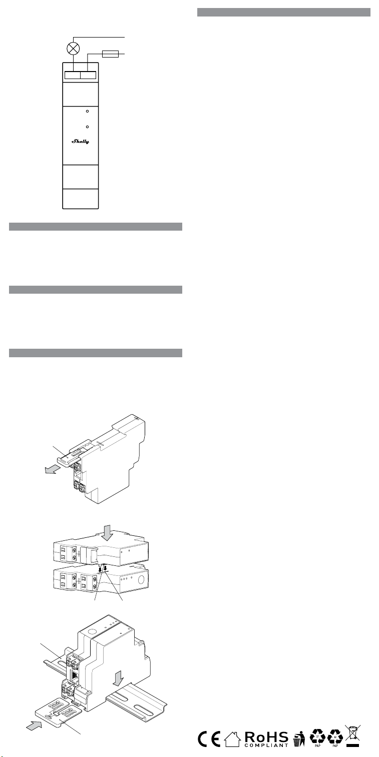
L
N
OI
Power
Out
A
AB
A
B
18/2023
EN - Schematic
DE - Schematische Darstellung
IT - Schema
Fig. 1
Fig. 2
Fig. 3
Fig. 4
EN
Legend
Device terminals:
• O: Relay output terminal
• I: Relay input terminal
Cables:
• N: Neutral cable
• L: Live (110 - 240 VAC) cable
DE
Legende
Geräteanschlüsse:
• O: Relaisausgang
• I: Relaiseingang
Kabel:
• N: Neutrales Kabel (Nullleiter)
• L: Laststromkreis (110-240V AC)
IT
Legenda
Terminali del dispositivo:
• O: Terminale di uscita relè
• I: Terminale di ingresso relè
Cavi:
• N: Cavo neutro
• L: Cavo sotto tensione (110-240 VCA)

EN
USER AND SAFETY GUIDE
SHELLY PRO 3EM SWITCH ADD-ON
Read before use
This document contains important technical and safety informa-
tion about the device, its safe use and installation.
⚠CAUTION! Before beginning the installation, please read careful-
ly and entirely this guide and any other documents accompanying
the device. Failure to follow the installation procedures could lead to
malfunction, danger to your health and life, violation of law or refus
-
al of legal and/or commercial guarantee (if any). Allterco Robotics
EOOD is not responsible for any loss or damage in case of incorrect
installation or improper operation of this device due to failure of fol-
lowing the user and safety instructions in this guide.
Product Introduction
Shelly Pro 3EM Switch Add-on (the Device) is a galvanically isolat-
ed switch that extends the features of the Shelly Pro 3EM allowing
the control of contactors or other electrical devices
Installation Instructions
⚠CAUTION! Danger of electrocution. Mounting/installation of
the Device to the power grid has to be performed with caution, by
a qualied electrician.
⚠CAUTION! Danger of electrocution. Every change in the connec-
tions has to be done after ensuring there is no voltage present at
the Device terminals.
⚠CAUTION! Use the Device only with a power grid and applianc-
es that comply with all applicable regulations. A short circuit in the
power grid or any appliance connected to the Device may damage it.
⚠CAUTION! Do not connect the Device to appliances exceeding
the given max load!
⚠CAUTION! Connect the Device only in the way shown in these
instructions. Any other method could cause damage and/or injury.
⚠CAUTION! Do not install the Device where it can get wet.
If you are installing the Shelly Pro 3EM Switch Add-on to a Shelly
Pro 3EM device that is already connected to the power grid, check
that the breakers are turned off and there is no voltage on the termi-
nals of the device you are attaching the Shelly Pro 3EM Switch Add-
on to. This can be done with a phase tester or multimeter. When
you are sure that there is no voltage, you can proceed to installing
the Shelly Pro 3EM Switch Add-on.
Remove the mounting bracket (A) of the Shelly Pro 3 EM as shown
in Fig. 2.
Attach the Shelly Pro 3EM Switch Add-on to the Shelly Pro 3EM
device as shown in Fig. 3
⚠CAUTION! Be very careful not to bend the Device header pins
g. 3(A) when inserting them into the Shelly Pro 3EM device header
connector g. 3(B).
Place the Shelly Pro 3EM with the attached Shelly Switch Add-on
on the DIN rail g. 4(A) and insert the supplied double mounting
bracket g. 4(B) to x the attached devices to the DIN rail.
You can now proceed to connecting the cables as shown in Fig.1.
⚠RECOMMENDATION: Connect the Device using solid single-core
cables.
Connect the load circuit to the O terminal and the Neutral cable.
Connect the I terminal to the circuit breaker.
If the Shelly Pro 3EM device, which the Shelly Pro 3EM Switch Add-
on is attached to, has not been connected to the power grid, install
it following its user and safety guide.
LED indication
• Power (red): Lit when power supply is connected.
• Out (red): Lit when the output relay contact is closed.
Specications
• Mounting: on a DIN rail, attached to a Shelly Pro 3EM
• Dimensions (HxWxD): 94x19x69 / 3.70x0.75x2.71 in
• Ambient temperature: -20 °C to 40 °C / -5 °F to 105 °F
• Max. altitude: 2000 m / 6562 ft
• Screw terminals max. torque: 0.4 Nm / 3.54 lbin
• Wire cross section: 0.5 to 2.5 mm² / 20 to 14 AWG
• Wire strip length: 6 to 7 mm / 0.24 to 0.28 in
• Power supply: 3.3 VDC and 12 VDC (from Shelly Pro 3EM device)
• Electrical consumption: < 1 W
• Max switching voltage AC: 240 V
• Max switching voltage DC: 30 V
• Max switching current: 2 A
• Potential-free contact: Yes
Declaration of conformity
Hereby, Allterco Robotics EOOD declares that the equipment type
Shelly Pro 3EM Switch Add-on is in compliance with Directive
2014/35/EU, 2014/30/EU, 2011/65/EU. The full text of the EU dec-
laration of conformity is available at the following internet address:
shelly.link/Pro3EM-switch-add-on_DoC
Manufacturer: Allterco Robotics EOOD
Address: 103 Cherni vrah Blvd., 1407 Soa, Bulgaria
Tel.: +359 2 988 7435
E-mail: support@shelly.cloud
Ocial website: https://www.shelly.cloud
Changes in the contact information data are published by the Man-
ufacturer on the ocial website. https://www.shelly.cloud
All rights to the trademark Shelly® and other intellectual rights as
-
sociated with this Device belong to Allterco Robotics EOOD.
DE
BENUTZER- UND SICHERHEITSHANDBUCH
SHELLY PRO 3EM SWITCH ADD-ON
Bitte vor Gebrauch durchlesen
Dieses Dokument enthält wichtige technische und sicherheits-
technische Informationen über das Gerät und seine sichere Ver-
wendung und Installation.
⚠ACHTUNG! Bevor Sie mit der Installation beginnen, lesen Sie bitte
die Begleitdokumentation sorgfältig und vollständig durch. Die Nicht
-
beachtung der empfohlenen Verfahren kann zu Fehlfunktionen, Le-
bensgefahr oder Gesetzesverstößen führen. Allterco Robotics EOOD
haftet nicht für Verluste oder Schäden im Falle einer falschen Installa-
tion oder Bedienung dieses Geräts.
Produktvorstellung
Shelly Pro 3EM Switch Add-on (das Gerät) ist ein galvanisch ge-
trennter Schalter, der die Funktionalität des Shelly Pro 3EM erweitert
und die Steuerung von Schützen oder anderen elektrischen Geräten
ermöglicht
Instructions d'installation
⚠VORSICHT! Gefahr eines Stromschlages. Die Montage/Instal-
lation des Geräts an das Stromnetz muss von einem qualizierten
Elektriker mit Vorsicht durchgeführt werden!
⚠VORSICHT! Es besteht Stromschlaggefahr. Bei jeder Änderung der
Anschlüsse muss sichergestellt werden, dass an den Klemmen des
Geräts keine Spannung anliegt!
⚠VORSICHT! Verwenden Sie das Gerät nur mit einem Stromnetz
und Geräten, die allen geltenden Vorschriften entsprechen. Ein Kurz-
schluss im Stromnetz oder in einem an das Gerät angeschlossenen
Gerätes kann dieses beschädigen!
⚠VORSICHT! Schließen Sie das Gerät nicht an Geräte an, die die
angegebene Höchstlast überschreiten!
⚠VORSICHT! Schließen Sie das Gerät nur auf die in dieser Anleitung
beschriebene Weise an. Jede andere Methode kann zu Schäden und/
oder Verletzungen führen!
⚠VORSICHT! Installieren Sie das Gerät nicht an einem Ort, an dem
es nass werden kann!
Wenn Sie das Shelly Pro 3EM Switch Add-on an einem Shelly Pro
3EM Gerät anbringen, das bereits mit dem Stromnetz verbunden ist,
vergewissern Sie sich, dass die Sicherungen ausgeschaltet sind und
keine Spannung an dem Gerät anliegt, an dem Sie das Shelly Pro
3EM Switch Add-on anbringen wollen. Verwenden Sie dazu ein Pha-
senprüfgerät oder ein Multimeter. Wenn Sie sicher sind, dass keine
Spannung mehr vorhanden ist, können Sie mit der Installation des
Shelly Pro 3EM Switch Add-on fortfahren.
Entfernen Sie die Halterung (A) des Shelly Pro 3 EM. wie in Abb. 2
gezeigt.
Befestigen Sie das Shelly Pro 3EM Switch Add-on am Shelly Pro 3EM
Gerät wie in Abb. 3 gezeigt.
⚠ACHTUNG! Achten Sie darauf, dass Sie die Pins des Gerätekopfes
abb. 3(A) nicht verbiegen, wenn Sie sie in den Shelly Pro 3EM Geräte-
kopfstecker abb. 3(B) stecken.
Platzieren Sie das Shelly Pro 3EM mit dem angebrachten Shelly
Switch Add-on auf der DIN-Schiene abb. 4(A) und setzen Sie die
mitgelieferte doppelte Montagehalterung abb. 4(B) ein, um die an-
geschlossenen Geräte auf der DIN-Schiene zu befestigen.
Sie können nun mit dem Anschließen der Kabel fortfahren, wie in
Abb. 1 gezeigt.
⚠EMPFEHLUNG: Schließen Sie das Gerät mit massiven einadrigen
Kabeln!
Schließen Sie den Lastkreis an die Klemme O und das Nullleiterkabel
an. Schließen Sie die Klemme I an den Schutzschalter an.
Wenn das Shelly Pro 3EM Gerät, an das der Shelly Pro 3EM Switch
Add-on angeschlossen ist, noch nicht mit dem Stromnetz verbunden
ist, installieren Sie es gemäß der Benutzer- und Sicherheitsanleitung.
LED-Anzeige
• Power (rot): Leuchtet, wenn die Stromversorgung angeschlossen
ist.
• Out (rot): Leuchtet, wenn der Ausgangsrelaiskontakt geschlossen
ist.
Spezikationen
• Montage: auf einer DIN-Schiene, die an einem Shelly Pro 3EM be-
festigt ist
• Abmessungen (HxBxT): 94x19x69 / 3.70x0.75x2.71in
• Umgebungstemperatur: -20 °C bis 40 °C / -5 °F bis 105 °F
• Max. Höhe ü.M.: 2000 m / 6562 ft
• Schraubklemmen max. Drehmoment: 0,4 Nm / 3.54 lbin
• Leitungsquerschnitt: 0,5 to 2,5 mm² / 20 to 14 AWG
• Länge des Drahtes: 6 to 7 mm / 0.24 to 0.28 in
• Spannungsversorgung: 3,3 VDC und 12 VDC (über Shelly Pro
3EM-Gerät)
• Stromverbrauch: < 1 W
• Maximale Schaltspannung AC: 240 V
• Maximale Schaltspannung DC: 30 V
• Max. Schaltstrom: 2 A
• Potentialfreier Kontakt: Ja
Konformitätserklärung
Hiermit erklärt Allterco Robotics EOOD, dass der Funkanlagentyp
Shelly Pro 3EM Switch Add-on der Richtlinie 2014/35/EU, 2014/30/
EU, 2011/65/EU entspricht. Den vollständigen Text der EU-Konformi
-
tätserklärung nden Sie unter folgender Internetadresse
shelly.link/Pro3EM-switch-add-on_DoC
Hersteller: Allterco Robotics EOOD
Adresse: 103 Cherni vrah Blvd., 1407 Soa, Bulgarien
Tel.: +359 2 988 7435
E-Mail: support@shelly.cloud
Ozielle Website: https://www.shelly.cloud
Änderungen der Kontaktdaten werden vom Hersteller auf dessen
oziellen Website veröffentlicht https://www.shelly.cloud
Alle Rechte an der Marke Shelly® und anderen geistigen Eigentums-
rechten im Zusammenhang mit diesem Gerät gehören Allterco Ro-
botics EOOD.
IT
GUIDA ALL'USO E ALLA SICUREZZA
SHELLY PRO 3EM SWITCH ADD-ON
Leggere prima dell'uso
Questo documento contiene importanti informazioni tecniche e
di sicurezza sul dispositivo e sul suo uso e installazione in sicu-
rezza.
⚠ATTENZIONE! Prima di iniziare l’installazione leggere attenta-
mente e completamente la documentazione allegata. La mancata
osservanza delle procedure consigliate potrebbe portare a malfun-
zionamenti, pericolo per la vita o violazione della legge. Allterco
Robotics EOOD non è responsabile per eventuali perdite o danni in
caso di installazione o funzionamento errati di questo dispositivo.
Introduzione al prodotto
Shelly Pro 3EM Switch Add-on (il Dispositivo) è un interruttore gal-
vanicamente isolato che estende la funzionalità di Shelly Pro 3EM
e consente il controllo di contattori o altri dispositivi elettrici
Istruzioni per l'installazione
⚠ATTENZIONE! Pericolo di folgorazione. Il montaggio/installazio-
ne del dispositivo alla rete elettrica deve essere eseguito con caute-
la da un elettricista qualicato.
⚠ATTENZIONE! Pericolo di folgorazione. Ogni modica dei colle
-
gamenti deve essere effettuata dopo essersi assicurati che non ci
sia tensione ai morsetti dell'apparecchio.
⚠ATTENZIONE! Utilizzare l'apparecchio solo con una rete elettrica
e con apparecchi conformi a tutte le norme vigenti. Un cortocircuito
nella rete elettrica o in qualsiasi apparecchio collegato all'apparec-
chio può danneggiare l'apparecchio.
⚠ATTENZIONE! Non collegare l'apparecchio ad apparecchi che
superano il carico massimo indicato!
⚠ATTENZIONE! Collegare l'apparecchio solo nel modo indicato
in queste istruzioni. Qualsiasi altro metodo potrebbe causare danni
e/o lesioni.
⚠ATTENZIONE! Non installare il dispositivo in un luogo che possa
bagnarsi.
Se stai installando Shelly Pro 3EM Switch Add-on su un dispositivo
Shelly Pro 3EM che è già collegato alla rete elettrica, controlla che
gli interruttori siano spenti e che non ci sia tensione sui terminali
del dispositivo a cui stai collegando Shelly Pro 3EM Switch Add-
on. Questo può essere fatto con un tester di fase o un multimetro.
Quando sei sicuro che non ci sia tensione, puoi procedere all'instal-
lazione del componente aggiuntivo Shelly Pro 3EM Switch Add-on.
Rimuovere la staffa di montaggio (A) di Shelly Pro 3 EM. come
mostrato in Fig. 2.
Collegare lo Shelly Pro 3EM Switch Add-on al dispositivo Shelly Pro
3EM come mostrato in Fig. 3.
⚠ATTENZIONE! Fare molta attenzione a non piegare i pin dell'inte-
stazione del dispositivo g. 3(A) quando li si inseriscono nel connet-
tore dell'intestazione g. 3(B) del dispositivo Shelly Pro 3EM.
Posizionare Shelly Pro 3EM con lo Shelly Switch Add-on collegato
sulla guida DIN g. 4(A) e inserire la staffa di montaggio doppia in
dotazione g. 4(B) per ssare i dispositivi collegati alla guida DIN.
È ora possibile procedere al collegamento dei cavi come mostrato
in Fig.1.
⚠RACCOMANDAZIONE Collegare il dispositivo utilizzando cavi
unipolari solidi.
Collegare il circuito di carico al terminale O e al cavo di neutro.
Collegare il terminale I all'interruttore automatico.
Se il dispositivo Shelly Pro 3EM, a cui è collegato Shelly Pro 3EM
Switch Add-on, non è stato collegato alla rete elettrica, installarlo
seguendo la guida per l'utente e la sicurezza.
LED indication
• Alimentazione (rosso): Acceso quando l'alimentazione è colle-
gata.
• Out (rosso): acceso quando il contatto del relè di uscita è chiuso.
Speciche tecniche
• Montaggio: su guida DIN, ssata a Shelly Pro 3EM
• Dimensioni (AxLxP): 94x19x69 / 3.70x0.75x2.71in
• Temperatura ambiente: da -20 °C a 40 °C / da -5 °F a 105 °F
• Altitudine massima: 2000 m / 6562 ft
• Morsetti a vite max. coppia: 0,4 Nm / 3.54 lbin
• Sezione del lo: 0,5 to 2,5 mm² / 20 to 14 AWG
• Lunghezza della striscia di lo: 6 to 7 mm / 0.24 to 0.28 in
• Alimentazione: 3,3 VDC e 12 VDC (dal dispositivo Shelly Pro
3EM)
• Consumo elettrico: < 1 W
• Max tensione di commutazione AC: 240 V
• Max tensione di commutazione DC: 30 V
• Corrente di commutazione massima: 2 A
• Contatto a potenziale zero: sì
Dichiarazione di conformità
Con la presente, Allterco Robotics EOOD dichiara che il tipo di ap-
parecchiatura radio Shelly Pro 3EM Switch Add-on è conforme alla
Direttiva 2014/35/UE, 2014/30/UE, 2011/65/UE. Il testo completo
della dichiarazione di conformità UE è disponibile al seguente in
-
dirizzo internet
shelly.link/Pro3EM-switch-add-on_DoC
Produttore: Allterco Robotics EOOD
Indirizzo: 103 Cherni vrah Blvd., 1407 Soa, Bulgarien
Tel.: +359 2 988 7435
E-mail: support@shelly.cloud
Sito web uciale: https://www.shelly.cloud
Le modiche ai dati di contatto sono pubblicate dal Produttore sul
sito Web uciale. https://www.shelly.cloud
Tutti i diritti sul marchio Shelly® e altri diritti intellettuali associati a
questo dispositivo appartengono a Allterco Robotics EOOD.
L
N
OI
Power
Out
A
AB
A
B
18/2023
EN - Schematic
DE - Schematische Darstellung
IT - Schema
Fig. 1
Fig. 2
Fig. 3
Fig. 4
EN
Legend
Device terminals:
• O: Relay output terminal
• I: Relay input terminal
Cables:
• N: Neutral cable
• L: Live (110 - 240 VAC) cable
DE
Legende
Geräteanschlüsse:
• O: Relaisausgang
• I: Relaiseingang
Kabel:
• N: Neutrales Kabel (Nullleiter)
• L: Laststromkreis (110-240V AC)
IT
Legenda
Terminali del dispositivo:
• O: Terminale di uscita relè
• I: Terminale di ingresso relè
Cavi:
• N: Cavo neutro
• L: Cavo sotto tensione (110-240 VCA)

ES
MANUAL DE USO Y SEGURIDAD
SHELLY PRO 3EM SWITCH ADD-ON
Lea antes de utilizar
Este documento contiene información técnica y de seguridad im-
portante sobre el aparato, su uso y su instalación segura.
⚠¡ATENCIÓN! Antes de comenzar la instalación, lea atentamente
y por completo la documentación adjunta. El incumplimiento de los
procedimientos recomendados puede provocar un mal funciona
-
miento, un peligro para su vida o una violación de la ley. Allterco Ro-
botics no se hace responsable de cualquier pérdida o daño debido a
una instalación o uso inadecuado de este dispositivo.
Resumen del producto
Shelly Pro 3EM Switch Add-on (el Dispositivo) es un interruptor
aislado galvánicamente que amplía las funciones del Shelly Pro
3EM permitiendo el control de contactores u otros dispositivos
eléctricos.
Instrucciones de instalación
⚠¡ATENCIÓN! Peligro de descarga eléctrica. El montaje/instala-
ción del aparato a la red eléctrica debe ser realizado con cuidado,
por un electricista cualicado.
⚠¡ATENCIÓN! Peligro de descarga eléctrica. Cualquier modica
-
ción de las conexiones debe realizarse después de asegurarse de
que no hay tensión en los terminales del Dispositivo.
⚠¡ATENCIÓN! Utilice el dispositivo sólo con una fuente de alimen-
tación y un equipo que cumplan con todas las normas aplicables. Un
cortocircuito en la red eléctrica o en cualquier dispositivo conectado
al aparato puede dañar el aparato.
⚠¡ATENCIÓN! No conecte el aparato a dispositivos que superen la
carga máxima indicada.
⚠¡ATENCIÓN! Conecte el aparato sólo de la manera indicada en
estas instrucciones. Cualquier otro método puede causar daños y/o
lesiones.
⚠¡ATENCIÓN! No instale el aparato en un lugar donde pueda mo-
jarse.
Si está instalando Shelly Pro 3EM Switch Add-on en un dispositivo
Shelly Pro 3EM que ya está conectado a la red eléctrica, verique
que los interruptores estén apagados y que no haya voltaje en los
terminales del dispositivo Shelly Pro 3EM al que está conectando
Shelly Pro 3EM Switch Add-on. Esto se puede hacer con un proba-
dor de fase o un multímetro. Cuando esté seguro de que no hay
voltaje, puede proceder a instalar el complemento Shelly Pro 3EM
Switch Add-on.
Retire el soporte de montaje (A) del Shelly Pro 3 EM. como se
muestra en la imagen 2.
Conecte el complemento Shelly Pro 3EM Switch Add-on al disposi-
tivo Shelly Pro 3EM como se muestra en la Fig. 3.
⚠¡ATENCIÓN! Tenga mucho cuidado de no doblar los pines del
cabezal del dispositivo g. 3(A) cuando los inserte en el conector
del cabezal g. 3(B) del dispositivo Shelly Pro 3EM.
Coloque Shelly Pro 3EM con Shelly Switch Add-On en el carril DIN
g. 4(A) e inserte el soporte de montaje doble suministrado g.
4(B) para jar los dispositivos al carril DIN.
Ahora puede proceder a conectar los cables como se muestra en
la imagen 1.
⚠¡RECOMENDACIÓN! Conecte el aparato con cables monocon-
ductores sólidos.
Conecte el circuito de carga al terminal O y al cable Neutro. Conec-
te el terminal I al disyuntor.
Si el dispositivo Shelly Pro 3EM, al que está conectado el comple-
mento Shelly Pro 3EM Switch Add-on, no ha sido conectado a la
red eléctrica, instálelo siguiendo su guía de uso y seguridad.
Indicación LED
• Power (rojo): se ilumina cuando la alimentación está conectada.
• Out (rojo): se ilumina cuando el contacto del relé de salida está
cerrado.
Especicaciones
• Montaje: en un carril DIN, jado a un Shelly Pro 3EM
• Dimensiones (AxAxP): 94x19x69 / 3.70x0.75x2.71in
• Temperatura ambiente : -20 °C a 40 °C / -5 °F a 105 °F
• Altitud máxima: 2000 m / 6562 ft
• Terminales de tornillo máx. par: 0,4 Nm / 3.54 lbin
• Sección transversal del cable: 0,5 to 2,5 mm² / 20 to 14 AWG
• Longitud de la tira de alambre: 6 to 7 mm / 0.24 to 0.28 in
• Alimentación: 3,3 V CC y 12 V CC (de Shelly Pro 3EM)
• Consumo eléctrico: < 1 W
• Tensión máxima de conmutación CA: 240 V
• Tensión de conmutación máx. CC: 30 V
• Corriente de conmutación máxima: 2 A
• Contacto libre de potencial: Sí
Declaración de conformidad
Allterco Robotics EOOD declara por la presente que el equipo de
radio tipo Shelly Pro 3EM Switch Add-on cumple con las directivas
2014/35/UE, 2014/30/UE, 2011/65/UE. El texto completo de la de
-
claración de conformidad de la UE está disponible en la siguiente
dirección web shelly.link/Pro3EM-switch-add-on_DoC
Fabricante: Allterco Robotics EOOD
Dirección: 103 Cherni vrah Blvd., 1407 Soa, Bulgarien
Tel: +359 2 988 7435
Correo electrónico: support@shelly.cloud
Sitio web ocial: https://www.shelly.cloud
Los cambios en la información de contacto son publicados por el
fabricante en el sitio web ocial.
https://www.shelly.cloud
Todos los derechos de las marcas Shelly®, y otros derechos de
propiedad intelectual asociados a este dispositivo pertenecen a
Allterco Robotics EOOD.
PT
GUIA DO UTILIZADOR E DE SEGURANÇA
SHELLY PRO 3EM SWITCH ADD-ON
Leia antes de utilizar
Este documento contém importante informação técnica e de
segurança relativa ao dispositivo, sua utilização segura e insta-
lação.
⚠ATENÇÃO! Antes de iniciar a instalação, por favor leia atenta-
mente e na íntegra a documentação incluída. O incumprimento dos
procedimentos recomendados poderão dar origem a avarias, perigo
à sua vida ou violação da lei. A Allterco Robotics EOOD não se res
-
ponsabiliza por quaisquer perdas ou danos em caso de uma incorre-
ta instalação ou incorreta utilização deste dispositivo.
Apresentação do Produto
Shelly Pro 3EM Switch Add-on (o Dispositivo) é um interruptor
isolado galvanicamente que estende a funcionalidade do Shelly
Pro 3EM e permite o controle de contatores ou outros dispositivos
elétricos
Instruções de Instalação
⚠ATENÇÃO! Perigo de eletrocussão. A montagem/instalação do
Dispositivo à rede elétrica deve ser executada com precaução, por
um eletricista qualicado.
⚠ATENÇÃO! Perigo de eletrocussão. Qualquer alteração nas liga-
ções só deve ser executada depois de assegurado de que não existe
qualquer voltagem nos terminais do Dispositivo.
⚠ATENÇÃO! Utilize o Dispositivo apenas com uma rede elétrica
e eletrodomésticos que estejam de acordo com os regulamentos
aplicáveis. Um curto-circuito na rede elétrica ou num dos eletrodo-
mésticos conectados poderá danicar o Dispositivo.
⚠ATENÇÃO! Não conecte o Dispositivo a electrodomésticos se
estes excederem a carga máxima permitida.
⚠ATENÇÃO! Conecte o Dispositivo apenas da forma ilustrada
nestas instruções. Qualquer outra forma poderá causar danos e/
ou acidentes.
⚠ATENÇÃO! Não instale o dispositivo num local que possa car
molhado.
Se estiver a instalar o Shelly Pro 3EM Switch Add-on num dispositi-
vo Shelly Pro 3EM que já se encontra conectado à rede de energia,
verique se os disjuntores estão desligados e que não existe qual-
quer voltagem nos terminais do dispositivo Shelly Pro 3EM onde
está a conectar o Shelly Pro 3EM Switch Add-on. Esta operação
pode ser executada com um medidor de fase ou um multímetro.
Quando se certicar de que não existe qualquer voltagem, pode
então prosseguir com a instalação do Shelly Pro 3EM Switch Ad-
d-on.
Remova o suporte de montagem (A) do Shelly Pro 3 EM. como
mostrado na Fig. 2.
Conecte o Shelly Pro 3EM Switch Add-on ao dispositivo Shelly Pro
3EM tal como ilustrado na Fig. 3.
⚠ATENÇÃO! Tenha cuidado para não dobrar os pinos g. 3(A) na
tomada de ligação do Dispositivo quando os inserir no conector g.
3(B) do dispositivo Shelly Pro 3EM.
Coloque o Shelly Pro 3EM com o Shelly Switch Add-on anexado no
trilho DIN g. 4(A) e insira o suporte de montagem duplo fornecido
g. 4(B) para xar os dispositivos conectados ao trilho DIN.
Agora você pode prosseguir para conectar os cabos conforme
mostrado na Fig.1.
⚠RECOMENDAÇÃO Conecte o Dispositivo usando cabos de nú-
cleo unilar.
Conecte o circuito de carga ao terminal O e ao cabo de Neutro.
Conecte o terminal I ao disjuntor.
Se o dispositivo Shelly Pro 3EM, ao qual o Shelly Pro 3EM Switch
Add-on está conectado, não se encontra conectado à rede energé-
tica, proceda à sua instalação de acordo com o guia de utilizador
e de segurança.
Indicação LED
• Power (vermelho): Acende quando a fonte de alimentação está
conectada.
• Out (vermelho): Acende quando o contato do relé de saída está
fechado.
Especicações
• Montagem: em trilho DIN, conectado a um Shelly Pro 3EM
• Dimensões (AxLxP): 94x19x69 / 3.70x0.75x2.71in
• Temperatura ambiente: -20 °C to 40 °C / -5 °F to 105 °F
• Altitude máxima: 2000 m / 6562 ft
• Torção máx. nos parafusos dos terminais: 0,4 Nm / 3.54 lbin
• Seção transversal do condutor: 0,5 to 2,5 mm² / 20 to 14 AWG
• Comprimento do condutor descarnado: 6 to 7 mm / 0.24 to 0.28 in
• Fonte de alimentação: 3,3 VDC e 12 VDC (do dispositivo Shelly
Pro 3EM)
• Consumo elétrico: < 1 W
• Voltagem máxima comutada CA: 240 V
• Voltagem máxima comutada CC: 30 V
• Corrente máxima de comutação: 2 A
• Contato livre de potencial: Sim
Declaração de conformidade
Allterco Robotics EOOD declara por la presente que el equipo de
radio tipo Shelly Pro 3EM Switch Add-on cumple con las directivas
2014/35/UE, 2014/30/UE, 2011/65/UE. El texto completo de la de
-
claración de conformidad de la UE está disponible en la siguiente
dirección web shelly.link/Pro3EM-switch-add-on_DoC
Fabricante: Allterco Robotics EOOD
Endereço: 103 Cherni vrah Blvd., 1407 Soa, Bulgária
Tel.: +359 2 988 7435
E-mail: support@shelly.cloud
Site ocial: https://www.shelly.cloud
Alterações nos endereços de contato são publicados pelo Fabri
-
cante no website ocial. https://www.shelly.cloud
Todos os direitos sobre a marca registada Shelly® e outros direi-
tos de propriedade intelectual associados a este Dispositivo per-
tencem a Allterco Robotics EOOD.
FR
NOTICE D'UTILISATION ET CONSIGNES DE
SÉCURITÉ
SHELLY PRO 3EM SWITCH ADD-ON
À lire avant utilisation
Ce document contient des informations techniques et des
consignes de sécurité importantes concernant le dispositif, son
utilisation et son installation.
⚠ATTENTION ! Avant de commencer l’installation, veuillez lire at-
tentivement et entièrement cette notice d'utilisation. Le non-respect
des procédures recommandées peut entraîner un dysfonctionne-
ment, représenter un danger ou être une violation de la loi. Allterco
Robotics EOOD n’est pas responsable des pertes ou des dommages
causés lors d’une installation ou utilisation inadéquate de ce dis-
positif.
Présentation du produit
Shelly Pro 3EM Switch Add-on (le Dispositif) est un interrupteur à
isolement galvaniquem qui augmente les fonctions de Shelly Pro
3EM en permettant de contrôler des contacteurs ou d'autres ap
-
pareils électriques.
Instructions d'installation
⚠ATTENTION ! Risque d'électrocution. Le montage/l'installation
du Dispositif sur le réseau électrique doit être effectué avec pru
-
dence, par un électricien qualié.
⚠ATTENTION ! Risque d'électrocution. Chaque modication des
connexions doit être effectuée après que vous vous soyez assurés
qu'il n'y ait aucune tension aux bornes du Dispositif.
⚠ATTENTION ! N'utilisez le Dispositif qu'avec un réseau électrique
et des appareils conformes à toutes les réglementations appli
-
cables. Un court-circuit sur le réseau électrique ou tout appareil
connecté au Dispositif peut l'endommager.
⚠ATTENTION ! Ne branchez pas le Dispositif à d'autres appareils
dont la charge maximale indiquée est dépassée !
⚠ATTENTION ! Suivez les instructions indiquées pour connecter le
Dispositif. Toute autre méthode pourrait engendrer des dommages
et/ou des blessures.
⚠ATTENTION ! N'installez pas le Dispositif dans un endroit sus-
ceptible d'être exposé à l'humidité.
Si vous installez le dispositif Shelly Pro 3EM Switch Add-on sur un
dispositif Shelly Pro 3EM déjà connecté au réseau électrique, véri
-
ez bien que le disjoncteur soit éteint et qu’il n’y ait pas de tension
aux bornes du dispositif Shelly Pro 3EM auquel vous connectez
le dispositif Shelly Pro 3EM Switch Add-on. Utilisez un testeur de
phase ou un multimètre. Lorsque vous êtes sûrs qu’il n’y a pas de
tension, vous pouvez procéder à l’installation de Shelly Pro 3EM
Switch Add-on.
Enlevez le support de montage (A) de Shelly Pro 3 EM, comme in-
diqué sur l'image 2.
Connectez le dispositif Shelly Pro 3EM Switch Add-on à Shelly Pro
3EM, comme illustré sur l'image 3.
⚠ATTENTION ! Faites attention à ne pas plier les en-tête de bro
-
ches du Dispositif l'image 3(A) lorsque vous les insérez dans le
connecteur d’en-tête l'image 3(B) du dispositif Shelly Pro 3EM.
Placez Shelly Pro 3EM avec Shelly Switch Add-On sur le rail DIN
l'image 4(A) et insérez le double support de montage fourni l'image
4(B) pour xer les dispositifs au rail DIN.
Vous pouvez maintenant procéder au branchement des câbles
comme indiqué sur l'image 1.
⚠RECOMMANDATION : Branchez le Dispositif à l'aide de câbles
monoconducteurs solides.
Branchez le circuit de charge à la borne O et au câble Neutre. Bran
-
chez la borne I au disjoncteur.
Si Shelly Pro 3EM, auquel Shelly Pro 3EM Switch Add-on est bran
-
ché, n’a pas été relié au réseau électrique, installez-le en suivant
son guide d’utilisation et de sécurité.
Indicateur LED
• Power (rouge) : s'allume lorsque l'alimentation est reliée.
• Out (rouge) : allumé lorsque le contact du relais de sortie est
fermé.
Caractéristiques techniques
• Montage : sur un rail DIN, xé à un Shelly Pro 3EM
• Dimensions (H x L x P) : 94x19x69 / 3.70x0.75x2.71in
• Température ambiante : -20 °C à 40 °C / -5 °F à 105 °F
• Altitude maximale : 2000 m / 6562 ft
• Serrage max. des dominos électriques : 0,4 Nm / 3.54 lbin
• Section du l : 0,5 to 2,5 mm² / 20 to 14 AWG
• Longueur du l dénudé : 6 to 7 mm / 0.24 to 0.28 in
• Alimentation électrique : 3,3 V DC et 12 V DC (à partir de Shelly
Pro 3EM)
• Consommation électrique : < 1 W
• Tension de commutation max. AC : 240 V
• Tension de commutation max. DC : 30 V
• Courant de commutation maximal : 2 A
• Contact libre de potentiel : Oui
Déclaration de conformité
Par la présente, Allterco Robotics EOOD déclare que le dispositif
Shelly Pro 3EM Switch Add-on est conforme à la directive 2014/35/
UE, 2014/30/UE, 2011/65/UE. Le texte complet de la déclaration
UE de conformité est disponible à l'adresse internet suivante :
shelly.link/Pro3EM-switch-add-on_DoC
Fabricant : Allterco Robotics EOOD
Adresse : 103, Boulevard "Cherni vrah", 1407 Soa, Bulgarie
Tél : +359 2 988 7435
Email : support@shelly.cloud
Site ociel : https://www.shelly.cloud
Les modications des coordonnées, faites par le fabricant, sont
publiées sur le site ociel. https://www.shelly.cloud
Tous les droits de la marque Shelly® et autres droits de proprié-
té intellectuelle associés à ce Dispositif appartiennent à Allterco
Robotics EOOD.
L
N
OI
Power
Out
A
AB
A
B
ES - Esquema
PT - Esquema
FR - Schéma
Fig. 1
Fig. 2
Fig. 3
Fig. 4
ES
Leyenda
Terminales del dispositivo:
• O: Terminal de salida de relé
• I: Terminal de entrada de relé
Cables:
• N: Cable neutro
• L: Cable vivo (110 - 240 VAC)
PT
Legenda
Terminais do dispositivo:
• O: Terminal de saída do relé
• I: Terminal de entrada do relé
Cabos:
• N: Cabo de Neutro
• L: Cabo de corrente (110-240 VCA)
FR
Légende
Bornes du dispositif :
• O : Borne de sortie du relais
• I : Borne d'entrée du relais
Câbles :
• N : Câble neutre
• L : Câble sous tension (110 - 240 VAC)
18/2023

ES
MANUAL DE USO Y SEGURIDAD
SHELLY PRO 3EM SWITCH ADD-ON
Lea antes de utilizar
Este documento contiene información técnica y de seguridad im-
portante sobre el aparato, su uso y su instalación segura.
⚠¡ATENCIÓN! Antes de comenzar la instalación, lea atentamente
y por completo la documentación adjunta. El incumplimiento de los
procedimientos recomendados puede provocar un mal funciona
-
miento, un peligro para su vida o una violación de la ley. Allterco Ro-
botics no se hace responsable de cualquier pérdida o daño debido a
una instalación o uso inadecuado de este dispositivo.
Resumen del producto
Shelly Pro 3EM Switch Add-on (el Dispositivo) es un interruptor
aislado galvánicamente que amplía las funciones del Shelly Pro
3EM permitiendo el control de contactores u otros dispositivos
eléctricos.
Instrucciones de instalación
⚠¡ATENCIÓN! Peligro de descarga eléctrica. El montaje/instala-
ción del aparato a la red eléctrica debe ser realizado con cuidado,
por un electricista cualicado.
⚠¡ATENCIÓN! Peligro de descarga eléctrica. Cualquier modica
-
ción de las conexiones debe realizarse después de asegurarse de
que no hay tensión en los terminales del Dispositivo.
⚠¡ATENCIÓN! Utilice el dispositivo sólo con una fuente de alimen-
tación y un equipo que cumplan con todas las normas aplicables. Un
cortocircuito en la red eléctrica o en cualquier dispositivo conectado
al aparato puede dañar el aparato.
⚠¡ATENCIÓN! No conecte el aparato a dispositivos que superen la
carga máxima indicada.
⚠¡ATENCIÓN! Conecte el aparato sólo de la manera indicada en
estas instrucciones. Cualquier otro método puede causar daños y/o
lesiones.
⚠¡ATENCIÓN! No instale el aparato en un lugar donde pueda mo-
jarse.
Si está instalando Shelly Pro 3EM Switch Add-on en un dispositivo
Shelly Pro 3EM que ya está conectado a la red eléctrica, verique
que los interruptores estén apagados y que no haya voltaje en los
terminales del dispositivo Shelly Pro 3EM al que está conectando
Shelly Pro 3EM Switch Add-on. Esto se puede hacer con un proba-
dor de fase o un multímetro. Cuando esté seguro de que no hay
voltaje, puede proceder a instalar el complemento Shelly Pro 3EM
Switch Add-on.
Retire el soporte de montaje (A) del Shelly Pro 3 EM. como se
muestra en la imagen 2.
Conecte el complemento Shelly Pro 3EM Switch Add-on al disposi-
tivo Shelly Pro 3EM como se muestra en la Fig. 3.
⚠¡ATENCIÓN! Tenga mucho cuidado de no doblar los pines del
cabezal del dispositivo g. 3(A) cuando los inserte en el conector
del cabezal g. 3(B) del dispositivo Shelly Pro 3EM.
Coloque Shelly Pro 3EM con Shelly Switch Add-On en el carril DIN
g. 4(A) e inserte el soporte de montaje doble suministrado g.
4(B) para jar los dispositivos al carril DIN.
Ahora puede proceder a conectar los cables como se muestra en
la imagen 1.
⚠¡RECOMENDACIÓN! Conecte el aparato con cables monocon-
ductores sólidos.
Conecte el circuito de carga al terminal O y al cable Neutro. Conec-
te el terminal I al disyuntor.
Si el dispositivo Shelly Pro 3EM, al que está conectado el comple-
mento Shelly Pro 3EM Switch Add-on, no ha sido conectado a la
red eléctrica, instálelo siguiendo su guía de uso y seguridad.
Indicación LED
• Power (rojo): se ilumina cuando la alimentación está conectada.
• Out (rojo): se ilumina cuando el contacto del relé de salida está
cerrado.
Especicaciones
• Montaje: en un carril DIN, jado a un Shelly Pro 3EM
• Dimensiones (AxAxP): 94x19x69 / 3.70x0.75x2.71in
• Temperatura ambiente : -20 °C a 40 °C / -5 °F a 105 °F
• Altitud máxima: 2000 m / 6562 ft
• Terminales de tornillo máx. par: 0,4 Nm / 3.54 lbin
• Sección transversal del cable: 0,5 to 2,5 mm² / 20 to 14 AWG
• Longitud de la tira de alambre: 6 to 7 mm / 0.24 to 0.28 in
• Alimentación: 3,3 V CC y 12 V CC (de Shelly Pro 3EM)
• Consumo eléctrico: < 1 W
• Tensión máxima de conmutación CA: 240 V
• Tensión de conmutación máx. CC: 30 V
• Corriente de conmutación máxima: 2 A
• Contacto libre de potencial: Sí
Declaración de conformidad
Allterco Robotics EOOD declara por la presente que el equipo de
radio tipo Shelly Pro 3EM Switch Add-on cumple con las directivas
2014/35/UE, 2014/30/UE, 2011/65/UE. El texto completo de la de
-
claración de conformidad de la UE está disponible en la siguiente
dirección web shelly.link/Pro3EM-switch-add-on_DoC
Fabricante: Allterco Robotics EOOD
Dirección: 103 Cherni vrah Blvd., 1407 Soa, Bulgarien
Tel: +359 2 988 7435
Correo electrónico: support@shelly.cloud
Sitio web ocial: https://www.shelly.cloud
Los cambios en la información de contacto son publicados por el
fabricante en el sitio web ocial.
https://www.shelly.cloud
Todos los derechos de las marcas Shelly®, y otros derechos de
propiedad intelectual asociados a este dispositivo pertenecen a
Allterco Robotics EOOD.
PT
GUIA DO UTILIZADOR E DE SEGURANÇA
SHELLY PRO 3EM SWITCH ADD-ON
Leia antes de utilizar
Este documento contém importante informação técnica e de
segurança relativa ao dispositivo, sua utilização segura e insta-
lação.
⚠ATENÇÃO! Antes de iniciar a instalação, por favor leia atenta-
mente e na íntegra a documentação incluída. O incumprimento dos
procedimentos recomendados poderão dar origem a avarias, perigo
à sua vida ou violação da lei. A Allterco Robotics EOOD não se res
-
ponsabiliza por quaisquer perdas ou danos em caso de uma incorre-
ta instalação ou incorreta utilização deste dispositivo.
Apresentação do Produto
Shelly Pro 3EM Switch Add-on (o Dispositivo) é um interruptor
isolado galvanicamente que estende a funcionalidade do Shelly
Pro 3EM e permite o controle de contatores ou outros dispositivos
elétricos
Instruções de Instalação
⚠ATENÇÃO! Perigo de eletrocussão. A montagem/instalação do
Dispositivo à rede elétrica deve ser executada com precaução, por
um eletricista qualicado.
⚠ATENÇÃO! Perigo de eletrocussão. Qualquer alteração nas liga-
ções só deve ser executada depois de assegurado de que não existe
qualquer voltagem nos terminais do Dispositivo.
⚠ATENÇÃO! Utilize o Dispositivo apenas com uma rede elétrica
e eletrodomésticos que estejam de acordo com os regulamentos
aplicáveis. Um curto-circuito na rede elétrica ou num dos eletrodo-
mésticos conectados poderá danicar o Dispositivo.
⚠ATENÇÃO! Não conecte o Dispositivo a electrodomésticos se
estes excederem a carga máxima permitida.
⚠ATENÇÃO! Conecte o Dispositivo apenas da forma ilustrada
nestas instruções. Qualquer outra forma poderá causar danos e/
ou acidentes.
⚠ATENÇÃO! Não instale o dispositivo num local que possa car
molhado.
Se estiver a instalar o Shelly Pro 3EM Switch Add-on num dispositi-
vo Shelly Pro 3EM que já se encontra conectado à rede de energia,
verique se os disjuntores estão desligados e que não existe qual-
quer voltagem nos terminais do dispositivo Shelly Pro 3EM onde
está a conectar o Shelly Pro 3EM Switch Add-on. Esta operação
pode ser executada com um medidor de fase ou um multímetro.
Quando se certicar de que não existe qualquer voltagem, pode
então prosseguir com a instalação do Shelly Pro 3EM Switch Ad-
d-on.
Remova o suporte de montagem (A) do Shelly Pro 3 EM. como
mostrado na Fig. 2.
Conecte o Shelly Pro 3EM Switch Add-on ao dispositivo Shelly Pro
3EM tal como ilustrado na Fig. 3.
⚠ATENÇÃO! Tenha cuidado para não dobrar os pinos g. 3(A) na
tomada de ligação do Dispositivo quando os inserir no conector g.
3(B) do dispositivo Shelly Pro 3EM.
Coloque o Shelly Pro 3EM com o Shelly Switch Add-on anexado no
trilho DIN g. 4(A) e insira o suporte de montagem duplo fornecido
g. 4(B) para xar os dispositivos conectados ao trilho DIN.
Agora você pode prosseguir para conectar os cabos conforme
mostrado na Fig.1.
⚠RECOMENDAÇÃO Conecte o Dispositivo usando cabos de nú-
cleo unilar.
Conecte o circuito de carga ao terminal O e ao cabo de Neutro.
Conecte o terminal I ao disjuntor.
Se o dispositivo Shelly Pro 3EM, ao qual o Shelly Pro 3EM Switch
Add-on está conectado, não se encontra conectado à rede energé-
tica, proceda à sua instalação de acordo com o guia de utilizador
e de segurança.
Indicação LED
• Power (vermelho): Acende quando a fonte de alimentação está
conectada.
• Out (vermelho): Acende quando o contato do relé de saída está
fechado.
Especicações
• Montagem: em trilho DIN, conectado a um Shelly Pro 3EM
• Dimensões (AxLxP): 94x19x69 / 3.70x0.75x2.71in
• Temperatura ambiente: -20 °C to 40 °C / -5 °F to 105 °F
• Altitude máxima: 2000 m / 6562 ft
• Torção máx. nos parafusos dos terminais: 0,4 Nm / 3.54 lbin
• Seção transversal do condutor: 0,5 to 2,5 mm² / 20 to 14 AWG
• Comprimento do condutor descarnado: 6 to 7 mm / 0.24 to 0.28 in
• Fonte de alimentação: 3,3 VDC e 12 VDC (do dispositivo Shelly
Pro 3EM)
• Consumo elétrico: < 1 W
• Voltagem máxima comutada CA: 240 V
• Voltagem máxima comutada CC: 30 V
• Corrente máxima de comutação: 2 A
• Contato livre de potencial: Sim
Declaração de conformidade
Allterco Robotics EOOD declara por la presente que el equipo de
radio tipo Shelly Pro 3EM Switch Add-on cumple con las directivas
2014/35/UE, 2014/30/UE, 2011/65/UE. El texto completo de la de
-
claración de conformidad de la UE está disponible en la siguiente
dirección web shelly.link/Pro3EM-switch-add-on_DoC
Fabricante: Allterco Robotics EOOD
Endereço: 103 Cherni vrah Blvd., 1407 Soa, Bulgária
Tel.: +359 2 988 7435
E-mail: support@shelly.cloud
Site ocial: https://www.shelly.cloud
Alterações nos endereços de contato são publicados pelo Fabri
-
cante no website ocial. https://www.shelly.cloud
Todos os direitos sobre a marca registada Shelly® e outros direi-
tos de propriedade intelectual associados a este Dispositivo per-
tencem a Allterco Robotics EOOD.
FR
NOTICE D'UTILISATION ET CONSIGNES DE
SÉCURITÉ
SHELLY PRO 3EM SWITCH ADD-ON
À lire avant utilisation
Ce document contient des informations techniques et des
consignes de sécurité importantes concernant le dispositif, son
utilisation et son installation.
⚠ATTENTION ! Avant de commencer l’installation, veuillez lire at-
tentivement et entièrement cette notice d'utilisation. Le non-respect
des procédures recommandées peut entraîner un dysfonctionne-
ment, représenter un danger ou être une violation de la loi. Allterco
Robotics EOOD n’est pas responsable des pertes ou des dommages
causés lors d’une installation ou utilisation inadéquate de ce dis-
positif.
Présentation du produit
Shelly Pro 3EM Switch Add-on (le Dispositif) est un interrupteur à
isolement galvaniquem qui augmente les fonctions de Shelly Pro
3EM en permettant de contrôler des contacteurs ou d'autres ap
-
pareils électriques.
Instructions d'installation
⚠ATTENTION ! Risque d'électrocution. Le montage/l'installation
du Dispositif sur le réseau électrique doit être effectué avec pru
-
dence, par un électricien qualié.
⚠ATTENTION ! Risque d'électrocution. Chaque modication des
connexions doit être effectuée après que vous vous soyez assurés
qu'il n'y ait aucune tension aux bornes du Dispositif.
⚠ATTENTION ! N'utilisez le Dispositif qu'avec un réseau électrique
et des appareils conformes à toutes les réglementations appli
-
cables. Un court-circuit sur le réseau électrique ou tout appareil
connecté au Dispositif peut l'endommager.
⚠ATTENTION ! Ne branchez pas le Dispositif à d'autres appareils
dont la charge maximale indiquée est dépassée !
⚠ATTENTION ! Suivez les instructions indiquées pour connecter le
Dispositif. Toute autre méthode pourrait engendrer des dommages
et/ou des blessures.
⚠ATTENTION ! N'installez pas le Dispositif dans un endroit sus-
ceptible d'être exposé à l'humidité.
Si vous installez le dispositif Shelly Pro 3EM Switch Add-on sur un
dispositif Shelly Pro 3EM déjà connecté au réseau électrique, véri
-
ez bien que le disjoncteur soit éteint et qu’il n’y ait pas de tension
aux bornes du dispositif Shelly Pro 3EM auquel vous connectez
le dispositif Shelly Pro 3EM Switch Add-on. Utilisez un testeur de
phase ou un multimètre. Lorsque vous êtes sûrs qu’il n’y a pas de
tension, vous pouvez procéder à l’installation de Shelly Pro 3EM
Switch Add-on.
Enlevez le support de montage (A) de Shelly Pro 3 EM, comme in-
diqué sur l'image 2.
Connectez le dispositif Shelly Pro 3EM Switch Add-on à Shelly Pro
3EM, comme illustré sur l'image 3.
⚠ATTENTION ! Faites attention à ne pas plier les en-tête de bro
-
ches du Dispositif l'image 3(A) lorsque vous les insérez dans le
connecteur d’en-tête l'image 3(B) du dispositif Shelly Pro 3EM.
Placez Shelly Pro 3EM avec Shelly Switch Add-On sur le rail DIN
l'image 4(A) et insérez le double support de montage fourni l'image
4(B) pour xer les dispositifs au rail DIN.
Vous pouvez maintenant procéder au branchement des câbles
comme indiqué sur l'image 1.
⚠RECOMMANDATION : Branchez le Dispositif à l'aide de câbles
monoconducteurs solides.
Branchez le circuit de charge à la borne O et au câble Neutre. Bran
-
chez la borne I au disjoncteur.
Si Shelly Pro 3EM, auquel Shelly Pro 3EM Switch Add-on est bran
-
ché, n’a pas été relié au réseau électrique, installez-le en suivant
son guide d’utilisation et de sécurité.
Indicateur LED
• Power (rouge) : s'allume lorsque l'alimentation est reliée.
• Out (rouge) : allumé lorsque le contact du relais de sortie est
fermé.
Caractéristiques techniques
• Montage : sur un rail DIN, xé à un Shelly Pro 3EM
• Dimensions (H x L x P) : 94x19x69 / 3.70x0.75x2.71in
• Température ambiante : -20 °C à 40 °C / -5 °F à 105 °F
• Altitude maximale : 2000 m / 6562 ft
• Serrage max. des dominos électriques : 0,4 Nm / 3.54 lbin
• Section du l : 0,5 to 2,5 mm² / 20 to 14 AWG
• Longueur du l dénudé : 6 to 7 mm / 0.24 to 0.28 in
• Alimentation électrique : 3,3 V DC et 12 V DC (à partir de Shelly
Pro 3EM)
• Consommation électrique : < 1 W
• Tension de commutation max. AC : 240 V
• Tension de commutation max. DC : 30 V
• Courant de commutation maximal : 2 A
• Contact libre de potentiel : Oui
Déclaration de conformité
Par la présente, Allterco Robotics EOOD déclare que le dispositif
Shelly Pro 3EM Switch Add-on est conforme à la directive 2014/35/
UE, 2014/30/UE, 2011/65/UE. Le texte complet de la déclaration
UE de conformité est disponible à l'adresse internet suivante :
shelly.link/Pro3EM-switch-add-on_DoC
Fabricant : Allterco Robotics EOOD
Adresse : 103, Boulevard "Cherni vrah", 1407 Soa, Bulgarie
Tél : +359 2 988 7435
Email : support@shelly.cloud
Site ociel : https://www.shelly.cloud
Les modications des coordonnées, faites par le fabricant, sont
publiées sur le site ociel. https://www.shelly.cloud
Tous les droits de la marque Shelly® et autres droits de proprié-
té intellectuelle associés à ce Dispositif appartiennent à Allterco
Robotics EOOD.
L
N
OI
Power
Out
A
AB
A
B
ES - Esquema
PT - Esquema
FR - Schéma
Fig. 1
Fig. 2
Fig. 3
Fig. 4
ES
Leyenda
Terminales del dispositivo:
• O: Terminal de salida de relé
• I: Terminal de entrada de relé
Cables:
• N: Cable neutro
• L: Cable vivo (110 - 240 VAC)
PT
Legenda
Terminais do dispositivo:
• O: Terminal de saída do relé
• I: Terminal de entrada do relé
Cabos:
• N: Cabo de Neutro
• L: Cabo de corrente (110-240 VCA)
FR
Légende
Bornes du dispositif :
• O : Borne de sortie du relais
• I : Borne d'entrée du relais
Câbles :
• N : Câble neutre
• L : Câble sous tension (110 - 240 VAC)
18/2023