EN
USER AND SAFETY GUIDE
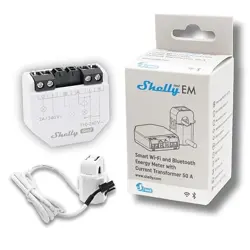
Triple phase Wi-Fi Energy Meter
Read before use
This document contains important technical and safety information
about the device and its safety use and installation.
⚠CAUTION! Before beginning the installation, please read this guide and
any other documents accompanying the device carefully and completely.
Failure to follow the installation procedures could lead to malfunction,
danger to your health and life, violation of the law or refusal of legal and/
or commercial guarantee (if any). Allterco Robotics EOOD is not respon-
sible for any loss or damage in case of incorrect installation or improper
operation of this device due to failure of following the user and safety
instructions in this guide.
Product Introduction
Shelly® is a line of innovative microprocessor-managed devices, which
allow remote control of electric appliances through a mobile phone, tab-
let, PC, or home automation system. Shelly® devices can work stand-
alone in a local Wi-Fi network or they can also be operated through cloud
home automation services. Shelly Cloud is such a service that can be
accessed using either Android or iOS mobile application, or with any
internet browser at https://home.shelly.cloud/. Shelly® devices can be
accessed, controlled and monitored remotely from any place where the
User has internet connectivity, as long as the devices are connected to a
Wi-Fi router and the Internet. Shelly® devices have embedded Web Inter-
face accessible at http://192.168.33.1 in the Wi-Fi network, created by
the device in Access Point mode, or at the URL address of the device in
the Wi-Fi network it is connected to. The embedded Web Interface can
be used to monitor and control the device, as well as adjust its settings.
Shelly® devices can communicate directly with other Wi-Fi devices
through HTTP protocol. An API is provided by Allterco Robotics EOOD.
For more information, please visit:
https://shelly-api-docs.shelly.cloud/#shelly-family-overview.
Shelly® devices are delivered with factory-installed rmware. If rmware
updates are necessary to keep the devices in conformity, including se-
curity updates, Allterco Robotics EOOD will provide the updates free of
charge through the device embedded Web Interface or Shelly Mobile
Application, where the information about the current rmware version is
available. The choice to install or not the Device rmware updates is Us-
er’s sole responsibility. Allterco Robotics EOOD shall not be liable for any
lack of conformity of the Device caused by failure of the User to install
the provided updates in a timely manner.
Control your home with your voice
All Shelly devices are compatible with Amazon Echo and Google Home.
Please see our step-by-step guide on:
https://shelly.cloud/support/compatibility/
Installation Instructions
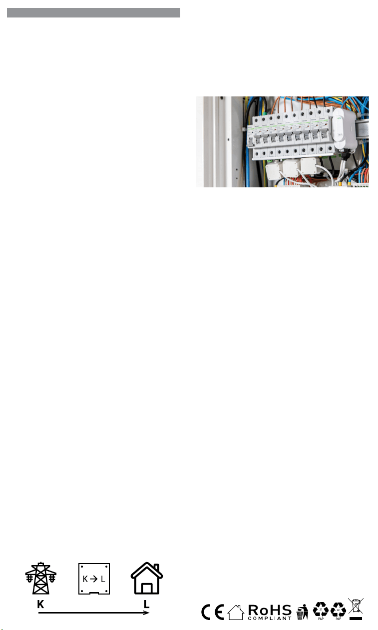
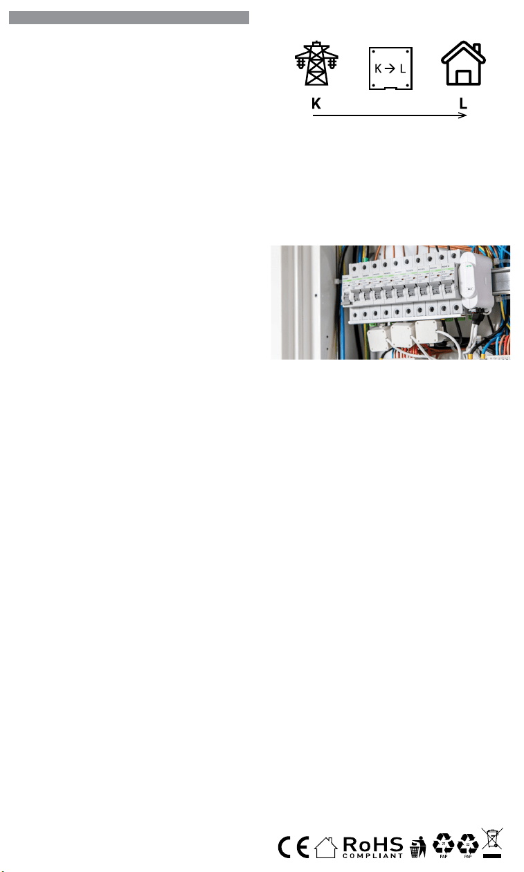
The Triple Phase Wi-Fi Energy Meter, Shelly 3EM by Allterco Robotics
is intended to be mounted next to the breakers, in order to monitor the
electric power through it, independent for each channel and heavy-du-
ty contactor control. Shelly may work as a standalone Device or as an
accessory to a home automation controller. Shelly 3EM can measurein-
comming and outgoing energy.
• Purpose of control: Operating
• Construction of control: Independently mounted
• Type 1.B Action
• Pollution Degree 2
• Impulse Voltage: 4000 V
Depending on how many phases you want to measure, you have to con-
nect your Shelly 3EM according to the provided scheme.
⚠CAUTION! Danger of electrocution. Mounting/installation of the De-
vice to the power grid has to be performed with caution, by a qualied
electrician.
⚠CAUTION! Danger of electrocution. Every change in the connections
has to be done after ensuring there is no voltage present at the Device
terminals.
⚠CAUTION! Use the Device only with a power grid and appliances which
comply with all applicable regulations. A short circuit in the power grid or
any appliance connected to the Device may damage the Device.
⚠CAUTION! Do not connect the Device to appliances exceeding the
given max load!
⚠CAUTION! Connect the Device only in the way shown in these instruc-
tions. Any other method could cause damage and/or injury.
⚠CAUTION! Do not install the Device where it can get wet.
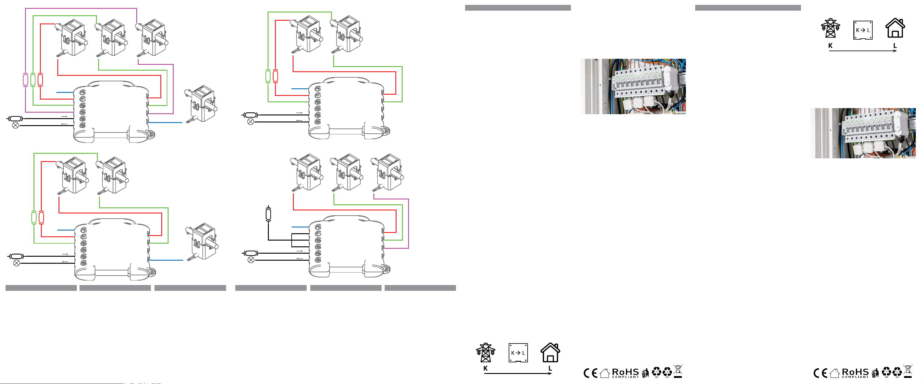
• First step is to install the measuring clamps over the wires. Open the
current transformer with screwdriver then clamp it over the desired
power cable. Do this for all the current transformers, please follow the
current ow diagram.
On the bottom of your Split core transformer, you will see an
arrow showing the direction of the energy flow.
split core current
transformer
DE
BENUTZER- UND SICHERHEITSLEITFADEN
Dreiphasiger WLAN-Energiezähler
Vor Benutzung lesen
Dieses Dokument enthält wichtige technische und sicherheitstechnische In-
formationen über das Gerät und seine sichere Verwendung und Installation.
⚠ACHTUNG! Bevor Sie mit der Installation beginnen, lesen Sie bitte die Be-
gleitdokumentation sorgfältig und vollständig durch. Die Nichtbeachtung der
empfohlenen Verfahren kann zu Fehlfunktionen, Lebensgefahr oder Gesetzes-
verstößen führen. Allterco Robotics EOOD haftet nicht für Verluste oder Schäden
im Falle einer falschen Installation oder Bedienung dieses Geräts.
Produkt-Einführung
Shelly® ist eine Reihe innovativer, mikroprozessorgesteuerter Geräte, die die
Fernsteuerung von Elektrogeräten über ein Mobiltelefon, ein Tablet, einen PC
oder ein Hausautomatisierungssystem ermöglichen. Shelly® Geräte können
eigenständig in einem lokalen Wi-Fi-Netzwerk arbeiten oder sie können auch
über Cloud-Dienste für die Hausautomation betrieben werden. Shelly Cloud ist
ein solcher Dienst, auf den entweder über eine Android- oder iOS-Mobilanwen-
dung oder über einen beliebigen Internetbrowser unter https://home.shelly.
cloud/ zugegriffen werden kann. Shelly® Geräte können von jedem Ort aus, an
dem der Benutzer eine Internetverbindung hat, angesprochen, gesteuert und
überwacht werden, solange die Geräte mit einem Wi-Fi-Router und dem Internet
verbunden sind. Shelly® Geräte verfügen über ein integriertes Web-Interface,
das unter http://192.168.33.1 im Wi-Fi-Netzwerk zugänglich ist, das vom Gerät
im Access Point-Modus erstellt wird, oder unter der URL-Adresse des Geräts im
Wi-Fi-Netzwerk, mit dem es verbunden ist. Das integrierte Web-Interface kann
zur Überwachung und Steuerung des Geräts sowie zur Anpassung seiner Ein-
stellungen verwendet werden.
Shelly® Geräte können direkt mit anderen Wi-Fi-Geräten über das HTTP-Pro-
tokoll kommunizieren. Eine API wird von Allterco Robotics EOOD bereitgestellt.
Für weitere Informationen besuchen Sie bitte:
https://shelly-api-docs.shelly.cloud/#shelly-family-overview.
Shelly® Geräte werden mit werkseitig installierter Firmware geliefert. Wenn
Firmware-Updates erforderlich sind, um die Geräte konform zu halten, ein-
schließlich Sicherheitsupdates, stellt Allterco Robotics EOOD die Updates
kostenlos über die in das Gerät eingebettete Webschnittstelle oder die Shelly
Mobile Application zur Verfügung, wo die Informationen über die aktuelle Firm-
ware-Version verfügbar sind. Die Entscheidung, die Firmware-Updates des Ge-
räts zu installieren oder nicht, liegt in der alleinigen Verantwortung des Benut-
zers. Allterco Robotics EOOD haftet nicht für Konformitätsmängel des Geräts,
die darauf zurückzuführen sind, dass der Benutzer die bereitgestellten Updates
nicht rechtzeitig installiert hat.
Steuern Sie Ihr Zuhause mit Ihrer Stimme
Alle Shelly-Geräte sind mit Amazon Echo und Google Home kompatibel. Bitte
lesen Sie unsere Schritt-für-Schritt-Anleitung auf:
https://shelly.cloud/support/compatibility/
Installationsanleitung
Der Dreiphasen-Wi-Fi-Energiezähler Shelly 3EM von Allterco Robotics soll
neben den Leistungsschaltern montiert werden, um die elektrische Leistung
unabhängig von jedem Kanal und einer Hochleistungsschützsteuerung zu
überwachen. Shelly kann als eigenständiges Gerät oder als Zubehör für eine
Heimautomatisierungssteuerung verwendet werden. Shelly 3EM kann einge-
hende und ausgehende Energie messen.
• Steuerungszweck: Betrieb
• Steuerungsaufbau: Unabhängig montiert
• Typ 1.B Aktion
• Verschmutzungsgrad 2
• Impulsspannung: 4000 V
Je nachdem, wie viele Phasen Sie messen möchten, müssen Sie Ihren Shelly
3EM nach dem mitgelieferten Schema anschließen.
⚠VORSICHT! Gefahr eines Stromschlages. Die Montage/Installation des
Geräts an das Stromnetz muss von einem qualizierten Elektriker mit Vorsicht
durchgeführt werden!
⚠VORSICHT! Es besteht Stromschlaggefahr. Bei jeder Änderung der An-
schlüsse muss sichergestellt werden, dass an den Klemmen des Geräts keine
Spannung anliegt!
⚠VORSICHT! Verwenden Sie das Gerät nur mit einem Stromnetz und Geräten,
die allen geltenden Vorschriften entsprechen. Ein Kurzschluss im Stromnetz
oder in einem an das Gerät angeschlossenen Gerätes kann dieses beschädigen!
⚠VORSICHT! Schließen Sie das Gerät nicht an Geräte an, die die angegebene
Höchstlast überschreiten!
⚠VORSICHT! Schließen Sie das Gerät nur auf die in dieser Anleitung beschrie-
bene Weise an. Jede andere Methode kann zu Schäden und/oder Verletzungen
führen!
⚠VORSICHT! Installieren Sie das Gerät nicht an einem Ort, an dem es nass
werden kann!
• Der erste Schritt besteht darin, die Messklemmen über den Drähten zu instal-
lieren. Öffnen Sie den Stromwandler mit einem Schraubendreher und klem-
men Sie ihn über das gewünschte Netzkabel. Führen Sie dies für alle Strom-
wandler aus, folgen Sie bitte dem Stromlaufplan.
• Second step is to wire the phase to the respective terminal on Shelly
3EM. Please use wire and tight it well with screw on the Shelly termi-
nals.
• Last step is to wire the power to the device. Please connect the power
wire to the respected terminal.
3 phase wiring scheme - Fig.1
2 phase (US) wiring - Fig.2
1 phase + separate solar power measurement wiring - Fig.3
1 phase wiring up to 3 different circuits - Fig.4
⚠CAUTION! Connect the current transformers accordingly for each
channel! Each current transformer is marked and calibrated for the respec-
tive input of the Device. Any improper connection will lead to incorrect
device measurement and visualisation.
Initial Inclusion
If you choose to use the Device with the Shelly Cloud mobile application
and Shelly Cloud service, instructions on how to connect the Device to
the Cloud and control it through the Shelly App can be found in the “App
Guide” www.shelly.cloud/app-guide.
The Shelly Mobile Application and Shelly Cloud service are not condi-
tions for the Device to function properly. This Device can be used stand-
alone or with various other home automation platforms and protocols.
⚠CAUTION! Do not allow children to play with the buttons/switches
connected to the Device. Keep the Devices for remote control of Shelly
(mobile phones, tablets, PCs) away from children.
Specication
• Power supply: 110-240 VAC, 50/60Hz
• Max measurement per channel: 120 A
• Relay Max Load: 10 A / 240 VAC
• Working temperature: -20°C up to 40°C
• Max RF output power: 10.82 dBm
• Radio protocol: Wi-Fi 802.11 b/g/n
• Frequency: 2412-2472 МHz; (Max. 2483.5 MHz)
• Operational range (depending on local construction):
- up to 50 m outdoors
- up to 30 m indoors
• Dimensions(HxWxL): 73x57x22 mm
• Electrical consumption: < 1W
• MQTT: Yes
• CoAP: Yes
• Webhooks (URL actions): up to 8 with 5 URLs per hook
• Schedules: 20
Energy Theft Detection
In order to have this feature available, you might need to update the rm-
ware of your device. With an additional split core current transformer,
connected to the IN- IN+ terminal of Shelly 3EM, you may receive a noti-
cation, if there is any energy theft or leakage. Please follow the wiring
diagrams on g. 1 and 2, dependent on your application.
Declaration of conformity
Hereby, Allterco Robotics EOOD declares that the radio equipment type
Shelly 3EM is in compliance with Directive 2014/53/EU, 2014/35/EU,
2014/30/EU, 2011/65/EU. The full text of the EU declaration of confor-
mity is available at the following internet address:
https://shelly.link/3em_DoC
Manufacturer: Allterco Robotics EOOD
Address: Bulgaria, Soa, 1407, 103 Cherni vrah Blvd.
Tel.: +359 2 988 7435
E-mail: support@shelly.cloud
Web: http://www.shelly.cloud
Changes in the contact data are published by the Manufacturer at the
ocial website of the Device http://www.shelly.cloud
All rights to trademark Shelly®, and other intellectual rights associated
with this Device belong to Allterco Robotics EOOD.
geteilter Kernstrom
Transformator
Auf der Unterseite Ihres Split-Core-Transformators sehen Sie
einen Pfeil, der die Richtung des Energieflusses anzeigt.
• Der zweite Schritt besteht darin, die Phase mit der entsprechenden Klemme
am Shelly 3EM zu verbinden. Bitte verwenden Sie Draht und ziehen Sie ihn gut
mit der Schraube an den Shelly-Klemmen fest.
• Der letzte Schritt besteht darin, das Gerät mit Strom zu versorgen. Bitte schlie-
ßen Sie das Stromkabel an die entsprechende Klemme an.
3-Phasen-Verdrahtungsschema – Abb. 1
2-Phasen-Verkabelung (US) – Abb.2
1 Phase + separate Verkabelung der Solarstrommessung – Abb.3
1-Phasen-Verkabelung bis zu 3 verschiedene Stromkreise – Abb.4
⚠ACHTUNG! Schließen Sie die Stromwandler für jeden Kanal entsprechend an!
Jeder Stromwandler ist für den jeweiligen Eingang des Gerätes gekennzeichnet
und kalibriert. Jeder unsachgemäße Anschluss führt zu einer falschen Geräte-
messung und -visualisierung.
Erstmalige Einbindung
Wenn Sie sich dafür entscheiden, das Gerät mit der Shelly Cloud App und dem
Shelly Cloud Service zu verwenden, nden Sie Anweisungen zur Verbindung
des Geräts mit der Cloud und zur Steuerung über die Shelly App im “App Guide”
www.shelly.cloud/app-guide
. Die Shelly Mobile App und der Shelly Cloud
Service sind keine Voraussetzung für das ordnungsgemäße Funktionieren des
Geräts. Dieses Gerät kann alleine, sowie mit verschiedenen anderen Hausauto-
matisierungsdiensten und -anwendungen verwendet werden.
⚠VORSICHT! Erlauben Sie Kindern nicht, mit den an das Gerät angeschlosse-
nen Tasten/Schaltern zu spielen. Halten Sie die Geräte zur Fernsteuerung des
Shelly (z.B.: Mobiltelefone, Tablets, PCs) von Kindern fern.
Spezikation
• Stromversorgung: 110-240 VAC, 50/60Hz
• Max. Messung pro Kanal: 120 A
• Relais max. Last: 10 A / 240 VAC
• Arbeitstemperatur: -20°C bis 40°C
• Max. HF-Ausgangsleistung: 10,82 dBm
• Funkprotokoll: Wi-Fi 802.11 b/g/n
• Frequenz: 2412-2472 МHz; (Max. 2483,5 MHz)
• Einsatzbereich (je nach örtlicher Bebauung):
- bis zu 50 m im Freien
- bis zu 30 m im Innenbereich
• Abmessungen (HxBxL): 73x57x22 mm
• Elektrischer Verbrauch: < 1W
• MQTT: Ja
• CoAP: Ja
• Webhooks (URL-Aktionen): 8 mit 5 URLs pro Hook
• Zeitpläne: 20
Erkennung von Energiediebstahl
Damit diese Funktion verfügbar ist, müssen Sie möglicherweise die Firmware
Ihres Geräts aktualisieren. Mit einem zusätzlichen Split-Core-Stromwandler, der
an die IN-IN+-Klemme von Shelly 3EM angeschlossen ist, erhalten Sie mög-
licherweise eine Benachrichtigung, wenn es zu Energiediebstahl oder -lecks
kommt. Bitte folgen Sie den Schaltplänen auf Abb. 1 und 2, abhängig von Ihrer
Anwendung.
Konformitätserklärung
Hiermit erklärt Allterco Robotics EOOD, dass der Funkanlagentyp Shelly 3EM
der Richtlinie 2014/53/EU, 2014/35/EU, 2014/30/EU, 2011/65/EU entspricht.
Der vollständige Text der EU-Konformitätserklärung ist unter folgender Inter-
netadresse abrufbar:
https://shelly.link/3em_DoC
Hersteller: Allterco Robotics EOOD
Adresse: Bulgarien, Soa, 1407, 103 Cherni vrah Blvd.
Tel.: +359 2 988 7435
E-Mail: support@shelly.cloud Web: http://www.shelly.cloud
Änderungen der Kontaktdaten werden vom Hersteller unter veröffentlicht die
ozielle Website des Geräts http://www.shelly.cloud
Alle Rechte an der Marke Shelly® und andere geistige Rechte im Zusammen-
hang mit diesem Gerät gehören Allterco Robotics EOOD.
IA- IA+
IB- IB+
IC- IC+
IN- IN+
N
N
Phase A
3 phase
breaker
breaker
0-220V AC or DC
Phase B Phase C
VA
VB
VC
I
O
Split core for Neutral*
*Split core is optional
and allows for detect
theft or energy leakage.
Fig.1
3 phase wiring scheme
N
N
Public network
2 phase
breaker
Solar power
VA
VB
VC
I
O
breaker
0-220V AC or DC
IA- IA+
IB- IB+
IC- IC+
IN- IN+
Fig.3
1 phase + separ
ate solar power
measur
ement wiring
N
N
Phase A
2 phase
breaker
Phase B
Split core for Neutral*
*Split core is optional
and allows for detect
theft or energy leakage.
VA
VB
VC
I
O
breaker
0-220V AC or DC
IA- IA+
IB- IB+
IC- IC+
IN- IN+
Fig.2
2 phase (US) wiring
N
N
Circuit 1
breaker
Circuit 2 Circuit 3
VA
VB
VC
I
O
breaker
0-220V AC or DC
IA- IA+
IB- IB+
IC- IC+
IN- IN+
Fig.4
1 phase wiring up t
o
3 different cir
cuits
EN
LEGEND – for Fig.1 till Fig.4
Left Side:
N - Neutral input (110-230V AC);
VA - Line input of Phase A (110-230V AC);
VB - Line input of Phase B (110-230V AC);
VC - Line input of Phase C (110-230V AC);
I - Line input for contactor control
O - Output for contactor control
Right Side:
IN- IN+ Input for current transformer of Neutral*
IC- IC+ Input for current transformer of Phase C
IB- IB+ Input for current transformer of Phase B
IA- IA+ Input for current transformer of Phase A
* Split core for Neutral is optional. It is not includ-
ed to the device.
DE
LEGENDE – für Abb.1 bis Abb.4
Linke Seite:
N - Neutraleingang (110-230V AC);
VA - Netzeingang von Phase A (110-230V AC);
VB - Netzeingang von Phase B (110-230V AC);
VC - Line-Eingang von Phase C (110-230V AC);
I - Netzeingang für Schützkontrolle
O - Ausgang für Schützkontrolle
Rechte Seite:
IN- IN+ Eingang für Stromwandler von Neutral*
IC- IC+ Eingang für Stromwandler von Phase C
IB- IB+ Eingang für Stromwandler von Phase B
IA- IA+ Eingang für Stromwandler von Phase A
* Geteilter Kern für Neutral ist optional. Es ist
nicht im Gerät enthalten.
IT
LEGENDA – per Fig.1 no a Fig.4
Lato sinistro:
N - Ingresso neutro (110-230V AC);
VA - Ingresso linea di Fase A (110-230V AC);
VB - Ingresso linea di Fase B (110-230V AC);
VC - Ingresso linea di Fase C (110-230V AC);
I - Ingresso linea per comando contattori
O - Uscita per controllo contattore
Lato destro:
IN- IN+ Ingresso per trasformatore di corrente
di Neutro*
IC- IC+ Ingresso per trasformatore di corrente
di Fase C
IB- IB+ Ingresso per trasformatore di corrente
di Fase B
IA- IA+ Ingresso per trasformatore di corrente
di Fase A
* Il nucleo diviso per Neutro è opzionale. Non è
incluso nel dispositivo.
ES
LEYENDA - para Img.1 a Img4.
El lado izquierdo:
N - Entrada de neutro (110-230V CA);
VA - Entrada de línea fase A (110-230V CA);
VB - Entrada de línea fase B (110-230V CA);
VC - Entrada de línea fase C (110-230V CA);
I - Entrada de línea para control de contactores.
O - Salida para el control del contactor
Lado derecho :
IN- IN+ Entrada para transformador de corriente
de neutro*
IC- IC+ Entrada para transformador de corriente
de fase C
IB- IB+ Entrada para transformador de corriente
de fase B
IA- IA+ Entrada para transformador de corriente
de fase A
* El núcleo dividido para el Neutral es opcional.
No está incluido en la unidad.
PT
LEGENDA – para a Fig.1 até à Fig.4
Lado Esquerdo:
N - Entrada de Neutro (110-230V CA);
VA - Entrada de linha da Fase A (110-230V CA);
VB - Entrada de linha da Fase B (110-230V CA);
VC - Entrada de linha da Fase C (110-230V CA);
I - Entrada de linha de controlo do Contactor
O - Saída de controlo do Contactor
Lado Direito:
IN- IN+ Entrada de Neutro* de corrente do trans-
formador
IC- IC+ Entrada da Fase C de corrente do trans-
formador
IB- IB+ Entrada da Fase B de corrente do trans-
formador
IA- IA+ Entrada da Fase A de corrente do trans-
formador
* Split core para Neutral é opcional. Não está
incluído no dispositivo.
FR
LÉGENDE - pour les Img.1 à Img.4
Côté gauche :
N - Entrée neutre (110-230V CA) ;
VA - Entrée de ligne de la phase A (110-230V CA);
VB - Entrée de ligne de la phase B (110-230V CA);
VC - Entrée de ligne de la phase C (110-230V CA);
I - Entrée de ligne pour le contrôle du contacteur.
O - Sortie pour le contrôle des contacteurs
Côté droit :
IN- IN+ Entrée pour transformateur de courant
du Neutre*
IC- IC+ Entrée pour transformateur de courant
de la Phase C
IB- IB+ Entrée pour transformateur de courant
de la Phase B
IA- IA+ Entrée pour transformateur de courant
de la Phase A
* Le noyau divisé pour le Neutre est optionnel. Il
n’est pas inclus dans l’appareil.
50/2022

EN
USER AND SAFETY GUIDE
Triple phase Wi-Fi Energy Meter
Read before use
This document contains important technical and safety information
about the device and its safety use and installation.
⚠CAUTION! Before beginning the installation, please read this guide and
any other documents accompanying the device carefully and completely.
Failure to follow the installation procedures could lead to malfunction,
danger to your health and life, violation of the law or refusal of legal and/
or commercial guarantee (if any). Allterco Robotics EOOD is not respon-
sible for any loss or damage in case of incorrect installation or improper
operation of this device due to failure of following the user and safety
instructions in this guide.
Product Introduction
Shelly® is a line of innovative microprocessor-managed devices, which
allow remote control of electric appliances through a mobile phone, tab-
let, PC, or home automation system. Shelly® devices can work stand-
alone in a local Wi-Fi network or they can also be operated through cloud
home automation services. Shelly Cloud is such a service that can be
accessed using either Android or iOS mobile application, or with any
internet browser at https://home.shelly.cloud/. Shelly® devices can be
accessed, controlled and monitored remotely from any place where the
User has internet connectivity, as long as the devices are connected to a
Wi-Fi router and the Internet. Shelly® devices have embedded Web Inter-
face accessible at http://192.168.33.1 in the Wi-Fi network, created by
the device in Access Point mode, or at the URL address of the device in
the Wi-Fi network it is connected to. The embedded Web Interface can
be used to monitor and control the device, as well as adjust its settings.
Shelly® devices can communicate directly with other Wi-Fi devices
through HTTP protocol. An API is provided by Allterco Robotics EOOD.
For more information, please visit:
https://shelly-api-docs.shelly.cloud/#shelly-family-overview.
Shelly® devices are delivered with factory-installed rmware. If rmware
updates are necessary to keep the devices in conformity, including se-
curity updates, Allterco Robotics EOOD will provide the updates free of
charge through the device embedded Web Interface or Shelly Mobile
Application, where the information about the current rmware version is
available. The choice to install or not the Device rmware updates is Us-
er’s sole responsibility. Allterco Robotics EOOD shall not be liable for any
lack of conformity of the Device caused by failure of the User to install
the provided updates in a timely manner.
Control your home with your voice
All Shelly devices are compatible with Amazon Echo and Google Home.
Please see our step-by-step guide on:
https://shelly.cloud/support/compatibility/
Installation Instructions
The Triple Phase Wi-Fi Energy Meter, Shelly 3EM by Allterco Robotics
is intended to be mounted next to the breakers, in order to monitor the
electric power through it, independent for each channel and heavy-du-
ty contactor control. Shelly may work as a standalone Device or as an
accessory to a home automation controller. Shelly 3EM can measurein-
comming and outgoing energy.
• Purpose of control: Operating
• Construction of control: Independently mounted
• Type 1.B Action
• Pollution Degree 2
• Impulse Voltage: 4000 V
Depending on how many phases you want to measure, you have to con-
nect your Shelly 3EM according to the provided scheme.
⚠CAUTION! Danger of electrocution. Mounting/installation of the De-
vice to the power grid has to be performed with caution, by a qualied
electrician.
⚠CAUTION! Danger of electrocution. Every change in the connections
has to be done after ensuring there is no voltage present at the Device
terminals.
⚠CAUTION! Use the Device only with a power grid and appliances which
comply with all applicable regulations. A short circuit in the power grid or
any appliance connected to the Device may damage the Device.
⚠CAUTION! Do not connect the Device to appliances exceeding the
given max load!
⚠CAUTION! Connect the Device only in the way shown in these instruc-
tions. Any other method could cause damage and/or injury.
⚠CAUTION! Do not install the Device where it can get wet.
• First step is to install the measuring clamps over the wires. Open the
current transformer with screwdriver then clamp it over the desired
power cable. Do this for all the current transformers, please follow the
current ow diagram.
On the bottom of your Split core transformer, you will see an
arrow showing the direction of the energy flow.
split core current
transformer
DE
BENUTZER- UND SICHERHEITSLEITFADEN
Dreiphasiger WLAN-Energiezähler
Vor Benutzung lesen
Dieses Dokument enthält wichtige technische und sicherheitstechnische In-
formationen über das Gerät und seine sichere Verwendung und Installation.
⚠ACHTUNG! Bevor Sie mit der Installation beginnen, lesen Sie bitte die Be-
gleitdokumentation sorgfältig und vollständig durch. Die Nichtbeachtung der
empfohlenen Verfahren kann zu Fehlfunktionen, Lebensgefahr oder Gesetzes-
verstößen führen. Allterco Robotics EOOD haftet nicht für Verluste oder Schäden
im Falle einer falschen Installation oder Bedienung dieses Geräts.
Produkt-Einführung
Shelly® ist eine Reihe innovativer, mikroprozessorgesteuerter Geräte, die die
Fernsteuerung von Elektrogeräten über ein Mobiltelefon, ein Tablet, einen PC
oder ein Hausautomatisierungssystem ermöglichen. Shelly® Geräte können
eigenständig in einem lokalen Wi-Fi-Netzwerk arbeiten oder sie können auch
über Cloud-Dienste für die Hausautomation betrieben werden. Shelly Cloud ist
ein solcher Dienst, auf den entweder über eine Android- oder iOS-Mobilanwen-
dung oder über einen beliebigen Internetbrowser unter https://home.shelly.
cloud/ zugegriffen werden kann. Shelly® Geräte können von jedem Ort aus, an
dem der Benutzer eine Internetverbindung hat, angesprochen, gesteuert und
überwacht werden, solange die Geräte mit einem Wi-Fi-Router und dem Internet
verbunden sind. Shelly® Geräte verfügen über ein integriertes Web-Interface,
das unter http://192.168.33.1 im Wi-Fi-Netzwerk zugänglich ist, das vom Gerät
im Access Point-Modus erstellt wird, oder unter der URL-Adresse des Geräts im
Wi-Fi-Netzwerk, mit dem es verbunden ist. Das integrierte Web-Interface kann
zur Überwachung und Steuerung des Geräts sowie zur Anpassung seiner Ein-
stellungen verwendet werden.
Shelly® Geräte können direkt mit anderen Wi-Fi-Geräten über das HTTP-Pro-
tokoll kommunizieren. Eine API wird von Allterco Robotics EOOD bereitgestellt.
Für weitere Informationen besuchen Sie bitte:
https://shelly-api-docs.shelly.cloud/#shelly-family-overview.
Shelly® Geräte werden mit werkseitig installierter Firmware geliefert. Wenn
Firmware-Updates erforderlich sind, um die Geräte konform zu halten, ein-
schließlich Sicherheitsupdates, stellt Allterco Robotics EOOD die Updates
kostenlos über die in das Gerät eingebettete Webschnittstelle oder die Shelly
Mobile Application zur Verfügung, wo die Informationen über die aktuelle Firm-
ware-Version verfügbar sind. Die Entscheidung, die Firmware-Updates des Ge-
räts zu installieren oder nicht, liegt in der alleinigen Verantwortung des Benut-
zers. Allterco Robotics EOOD haftet nicht für Konformitätsmängel des Geräts,
die darauf zurückzuführen sind, dass der Benutzer die bereitgestellten Updates
nicht rechtzeitig installiert hat.
Steuern Sie Ihr Zuhause mit Ihrer Stimme
Alle Shelly-Geräte sind mit Amazon Echo und Google Home kompatibel. Bitte
lesen Sie unsere Schritt-für-Schritt-Anleitung auf:
https://shelly.cloud/support/compatibility/
Installationsanleitung
Der Dreiphasen-Wi-Fi-Energiezähler Shelly 3EM von Allterco Robotics soll
neben den Leistungsschaltern montiert werden, um die elektrische Leistung
unabhängig von jedem Kanal und einer Hochleistungsschützsteuerung zu
überwachen. Shelly kann als eigenständiges Gerät oder als Zubehör für eine
Heimautomatisierungssteuerung verwendet werden. Shelly 3EM kann einge-
hende und ausgehende Energie messen.
• Steuerungszweck: Betrieb
• Steuerungsaufbau: Unabhängig montiert
• Typ 1.B Aktion
• Verschmutzungsgrad 2
• Impulsspannung: 4000 V
Je nachdem, wie viele Phasen Sie messen möchten, müssen Sie Ihren Shelly
3EM nach dem mitgelieferten Schema anschließen.
⚠VORSICHT! Gefahr eines Stromschlages. Die Montage/Installation des
Geräts an das Stromnetz muss von einem qualizierten Elektriker mit Vorsicht
durchgeführt werden!
⚠VORSICHT! Es besteht Stromschlaggefahr. Bei jeder Änderung der An-
schlüsse muss sichergestellt werden, dass an den Klemmen des Geräts keine
Spannung anliegt!
⚠VORSICHT! Verwenden Sie das Gerät nur mit einem Stromnetz und Geräten,
die allen geltenden Vorschriften entsprechen. Ein Kurzschluss im Stromnetz
oder in einem an das Gerät angeschlossenen Gerätes kann dieses beschädigen!
⚠VORSICHT! Schließen Sie das Gerät nicht an Geräte an, die die angegebene
Höchstlast überschreiten!
⚠VORSICHT! Schließen Sie das Gerät nur auf die in dieser Anleitung beschrie-
bene Weise an. Jede andere Methode kann zu Schäden und/oder Verletzungen
führen!
⚠VORSICHT! Installieren Sie das Gerät nicht an einem Ort, an dem es nass
werden kann!
• Der erste Schritt besteht darin, die Messklemmen über den Drähten zu instal-
lieren. Öffnen Sie den Stromwandler mit einem Schraubendreher und klem-
men Sie ihn über das gewünschte Netzkabel. Führen Sie dies für alle Strom-
wandler aus, folgen Sie bitte dem Stromlaufplan.
• Second step is to wire the phase to the respective terminal on Shelly
3EM. Please use wire and tight it well with screw on the Shelly termi-
nals.
• Last step is to wire the power to the device. Please connect the power
wire to the respected terminal.
3 phase wiring scheme - Fig.1
2 phase (US) wiring - Fig.2
1 phase + separate solar power measurement wiring - Fig.3
1 phase wiring up to 3 different circuits - Fig.4
⚠CAUTION! Connect the current transformers accordingly for each
channel! Each current transformer is marked and calibrated for the respec-
tive input of the Device. Any improper connection will lead to incorrect
device measurement and visualisation.
Initial Inclusion
If you choose to use the Device with the Shelly Cloud mobile application
and Shelly Cloud service, instructions on how to connect the Device to
the Cloud and control it through the Shelly App can be found in the “App
Guide” www.shelly.cloud/app-guide.
The Shelly Mobile Application and Shelly Cloud service are not condi-
tions for the Device to function properly. This Device can be used stand-
alone or with various other home automation platforms and protocols.
⚠CAUTION! Do not allow children to play with the buttons/switches
connected to the Device. Keep the Devices for remote control of Shelly
(mobile phones, tablets, PCs) away from children.
Specication
• Power supply: 110-240 VAC, 50/60Hz
• Max measurement per channel: 120 A
• Relay Max Load: 10 A / 240 VAC
• Working temperature: -20°C up to 40°C
• Max RF output power: 10.82 dBm
• Radio protocol: Wi-Fi 802.11 b/g/n
• Frequency: 2412-2472 МHz; (Max. 2483.5 MHz)
• Operational range (depending on local construction):
- up to 50 m outdoors
- up to 30 m indoors
• Dimensions(HxWxL): 73x57x22 mm
• Electrical consumption: < 1W
• MQTT: Yes
• CoAP: Yes
• Webhooks (URL actions): up to 8 with 5 URLs per hook
• Schedules: 20
Energy Theft Detection
In order to have this feature available, you might need to update the rm-
ware of your device. With an additional split core current transformer,
connected to the IN- IN+ terminal of Shelly 3EM, you may receive a noti-
cation, if there is any energy theft or leakage. Please follow the wiring
diagrams on g. 1 and 2, dependent on your application.
Declaration of conformity
Hereby, Allterco Robotics EOOD declares that the radio equipment type
Shelly 3EM is in compliance with Directive 2014/53/EU, 2014/35/EU,
2014/30/EU, 2011/65/EU. The full text of the EU declaration of confor-
mity is available at the following internet address:
https://shelly.link/3em_DoC
Manufacturer: Allterco Robotics EOOD
Address: Bulgaria, Soa, 1407, 103 Cherni vrah Blvd.
Tel.: +359 2 988 7435
E-mail: support@shelly.cloud
Web: http://www.shelly.cloud
Changes in the contact data are published by the Manufacturer at the
ocial website of the Device http://www.shelly.cloud
All rights to trademark Shelly®, and other intellectual rights associated
with this Device belong to Allterco Robotics EOOD.
geteilter Kernstrom
Transformator
Auf der Unterseite Ihres Split-Core-Transformators sehen Sie
einen Pfeil, der die Richtung des Energieflusses anzeigt.
• Der zweite Schritt besteht darin, die Phase mit der entsprechenden Klemme
am Shelly 3EM zu verbinden. Bitte verwenden Sie Draht und ziehen Sie ihn gut
mit der Schraube an den Shelly-Klemmen fest.
• Der letzte Schritt besteht darin, das Gerät mit Strom zu versorgen. Bitte schlie-
ßen Sie das Stromkabel an die entsprechende Klemme an.
3-Phasen-Verdrahtungsschema – Abb. 1
2-Phasen-Verkabelung (US) – Abb.2
1 Phase + separate Verkabelung der Solarstrommessung – Abb.3
1-Phasen-Verkabelung bis zu 3 verschiedene Stromkreise – Abb.4
⚠ACHTUNG! Schließen Sie die Stromwandler für jeden Kanal entsprechend an!
Jeder Stromwandler ist für den jeweiligen Eingang des Gerätes gekennzeichnet
und kalibriert. Jeder unsachgemäße Anschluss führt zu einer falschen Geräte-
messung und -visualisierung.
Erstmalige Einbindung
Wenn Sie sich dafür entscheiden, das Gerät mit der Shelly Cloud App und dem
Shelly Cloud Service zu verwenden, nden Sie Anweisungen zur Verbindung
des Geräts mit der Cloud und zur Steuerung über die Shelly App im “App Guide”
www.shelly.cloud/app-guide
. Die Shelly Mobile App und der Shelly Cloud
Service sind keine Voraussetzung für das ordnungsgemäße Funktionieren des
Geräts. Dieses Gerät kann alleine, sowie mit verschiedenen anderen Hausauto-
matisierungsdiensten und -anwendungen verwendet werden.
⚠VORSICHT! Erlauben Sie Kindern nicht, mit den an das Gerät angeschlosse-
nen Tasten/Schaltern zu spielen. Halten Sie die Geräte zur Fernsteuerung des
Shelly (z.B.: Mobiltelefone, Tablets, PCs) von Kindern fern.
Spezikation
• Stromversorgung: 110-240 VAC, 50/60Hz
• Max. Messung pro Kanal: 120 A
• Relais max. Last: 10 A / 240 VAC
• Arbeitstemperatur: -20°C bis 40°C
• Max. HF-Ausgangsleistung: 10,82 dBm
• Funkprotokoll: Wi-Fi 802.11 b/g/n
• Frequenz: 2412-2472 МHz; (Max. 2483,5 MHz)
• Einsatzbereich (je nach örtlicher Bebauung):
- bis zu 50 m im Freien
- bis zu 30 m im Innenbereich
• Abmessungen (HxBxL): 73x57x22 mm
• Elektrischer Verbrauch: < 1W
• MQTT: Ja
• CoAP: Ja
• Webhooks (URL-Aktionen): 8 mit 5 URLs pro Hook
• Zeitpläne: 20
Erkennung von Energiediebstahl
Damit diese Funktion verfügbar ist, müssen Sie möglicherweise die Firmware
Ihres Geräts aktualisieren. Mit einem zusätzlichen Split-Core-Stromwandler, der
an die IN-IN+-Klemme von Shelly 3EM angeschlossen ist, erhalten Sie mög-
licherweise eine Benachrichtigung, wenn es zu Energiediebstahl oder -lecks
kommt. Bitte folgen Sie den Schaltplänen auf Abb. 1 und 2, abhängig von Ihrer
Anwendung.
Konformitätserklärung
Hiermit erklärt Allterco Robotics EOOD, dass der Funkanlagentyp Shelly 3EM
der Richtlinie 2014/53/EU, 2014/35/EU, 2014/30/EU, 2011/65/EU entspricht.
Der vollständige Text der EU-Konformitätserklärung ist unter folgender Inter-
netadresse abrufbar:
https://shelly.link/3em_DoC
Hersteller: Allterco Robotics EOOD
Adresse: Bulgarien, Soa, 1407, 103 Cherni vrah Blvd.
Tel.: +359 2 988 7435
E-Mail: support@shelly.cloud Web: http://www.shelly.cloud
Änderungen der Kontaktdaten werden vom Hersteller unter veröffentlicht die
ozielle Website des Geräts http://www.shelly.cloud
Alle Rechte an der Marke Shelly® und andere geistige Rechte im Zusammen-
hang mit diesem Gerät gehören Allterco Robotics EOOD.
IA- IA+
IB- IB+
IC- IC+
IN- IN+
N
N
Phase A
3 phase
breaker
breaker
0-220V AC or DC
Phase B Phase C
VA
VB
VC
I
O
Split core for Neutral*
*Split core is optional
and allows for detect
theft or energy leakage.
Fig.1
3 phase wiring scheme
N
N
Public network
2 phase
breaker
Solar power
VA
VB
VC
I
O
breaker
0-220V AC or DC
IA- IA+
IB- IB+
IC- IC+
IN- IN+
Fig.3
1 phase + separ
ate solar power
measur
ement wiring
N
N
Phase A
2 phase
breaker
Phase B
Split core for Neutral*
*Split core is optional
and allows for detect
theft or energy leakage.
VA
VB
VC
I
O
breaker
0-220V AC or DC
IA- IA+
IB- IB+
IC- IC+
IN- IN+
Fig.2
2 phase (US) wiring
N
N
Circuit 1
breaker
Circuit 2 Circuit 3
VA
VB
VC
I
O
breaker
0-220V AC or DC
IA- IA+
IB- IB+
IC- IC+
IN- IN+
Fig.4
1 phase wiring up t
o
3 different cir
cuits
EN
LEGEND – for Fig.1 till Fig.4
Left Side:
N - Neutral input (110-230V AC);
VA - Line input of Phase A (110-230V AC);
VB - Line input of Phase B (110-230V AC);
VC - Line input of Phase C (110-230V AC);
I - Line input for contactor control
O - Output for contactor control
Right Side:
IN- IN+ Input for current transformer of Neutral*
IC- IC+ Input for current transformer of Phase C
IB- IB+ Input for current transformer of Phase B
IA- IA+ Input for current transformer of Phase A
* Split core for Neutral is optional. It is not includ-
ed to the device.
DE
LEGENDE – für Abb.1 bis Abb.4
Linke Seite:
N - Neutraleingang (110-230V AC);
VA - Netzeingang von Phase A (110-230V AC);
VB - Netzeingang von Phase B (110-230V AC);
VC - Line-Eingang von Phase C (110-230V AC);
I - Netzeingang für Schützkontrolle
O - Ausgang für Schützkontrolle
Rechte Seite:
IN- IN+ Eingang für Stromwandler von Neutral*
IC- IC+ Eingang für Stromwandler von Phase C
IB- IB+ Eingang für Stromwandler von Phase B
IA- IA+ Eingang für Stromwandler von Phase A
* Geteilter Kern für Neutral ist optional. Es ist
nicht im Gerät enthalten.
IT
LEGENDA – per Fig.1 no a Fig.4
Lato sinistro:
N - Ingresso neutro (110-230V AC);
VA - Ingresso linea di Fase A (110-230V AC);
VB - Ingresso linea di Fase B (110-230V AC);
VC - Ingresso linea di Fase C (110-230V AC);
I - Ingresso linea per comando contattori
O - Uscita per controllo contattore
Lato destro:
IN- IN+ Ingresso per trasformatore di corrente
di Neutro*
IC- IC+ Ingresso per trasformatore di corrente
di Fase C
IB- IB+ Ingresso per trasformatore di corrente
di Fase B
IA- IA+ Ingresso per trasformatore di corrente
di Fase A
* Il nucleo diviso per Neutro è opzionale. Non è
incluso nel dispositivo.
ES
LEYENDA - para Img.1 a Img4.
El lado izquierdo:
N - Entrada de neutro (110-230V CA);
VA - Entrada de línea fase A (110-230V CA);
VB - Entrada de línea fase B (110-230V CA);
VC - Entrada de línea fase C (110-230V CA);
I - Entrada de línea para control de contactores.
O - Salida para el control del contactor
Lado derecho :
IN- IN+ Entrada para transformador de corriente
de neutro*
IC- IC+ Entrada para transformador de corriente
de fase C
IB- IB+ Entrada para transformador de corriente
de fase B
IA- IA+ Entrada para transformador de corriente
de fase A
* El núcleo dividido para el Neutral es opcional.
No está incluido en la unidad.
PT
LEGENDA – para a Fig.1 até à Fig.4
Lado Esquerdo:
N - Entrada de Neutro (110-230V CA);
VA - Entrada de linha da Fase A (110-230V CA);
VB - Entrada de linha da Fase B (110-230V CA);
VC - Entrada de linha da Fase C (110-230V CA);
I - Entrada de linha de controlo do Contactor
O - Saída de controlo do Contactor
Lado Direito:
IN- IN+ Entrada de Neutro* de corrente do trans-
formador
IC- IC+ Entrada da Fase C de corrente do trans-
formador
IB- IB+ Entrada da Fase B de corrente do trans-
formador
IA- IA+ Entrada da Fase A de corrente do trans-
formador
* Split core para Neutral é opcional. Não está
incluído no dispositivo.
FR
LÉGENDE - pour les Img.1 à Img.4
Côté gauche :
N - Entrée neutre (110-230V CA) ;
VA - Entrée de ligne de la phase A (110-230V CA);
VB - Entrée de ligne de la phase B (110-230V CA);
VC - Entrée de ligne de la phase C (110-230V CA);
I - Entrée de ligne pour le contrôle du contacteur.
O - Sortie pour le contrôle des contacteurs
Côté droit :
IN- IN+ Entrée pour transformateur de courant
du Neutre*
IC- IC+ Entrée pour transformateur de courant
de la Phase C
IB- IB+ Entrée pour transformateur de courant
de la Phase B
IA- IA+ Entrée pour transformateur de courant
de la Phase A
* Le noyau divisé pour le Neutre est optionnel. Il
n’est pas inclus dans l’appareil.
50/2022
EN
USER AND SAFETY GUIDE
Triple phase Wi-Fi Energy Meter
Read before use
This document contains important technical and safety information
about the device and its safety use and installation.
⚠CAUTION! Before beginning the installation, please read this guide and
any other documents accompanying the device carefully and completely.
Failure to follow the installation procedures could lead to malfunction,
danger to your health and life, violation of the law or refusal of legal and/
or commercial guarantee (if any). Allterco Robotics EOOD is not respon-
sible for any loss or damage in case of incorrect installation or improper
operation of this device due to failure of following the user and safety
instructions in this guide.
Product Introduction
Shelly® is a line of innovative microprocessor-managed devices, which
allow remote control of electric appliances through a mobile phone, tab-
let, PC, or home automation system. Shelly® devices can work stand-
alone in a local Wi-Fi network or they can also be operated through cloud
home automation services. Shelly Cloud is such a service that can be
accessed using either Android or iOS mobile application, or with any
internet browser at https://home.shelly.cloud/. Shelly® devices can be
accessed, controlled and monitored remotely from any place where the
User has internet connectivity, as long as the devices are connected to a
Wi-Fi router and the Internet. Shelly® devices have embedded Web Inter-
face accessible at http://192.168.33.1 in the Wi-Fi network, created by
the device in Access Point mode, or at the URL address of the device in
the Wi-Fi network it is connected to. The embedded Web Interface can
be used to monitor and control the device, as well as adjust its settings.
Shelly® devices can communicate directly with other Wi-Fi devices
through HTTP protocol. An API is provided by Allterco Robotics EOOD.
For more information, please visit:
https://shelly-api-docs.shelly.cloud/#shelly-family-overview.
Shelly® devices are delivered with factory-installed rmware. If rmware
updates are necessary to keep the devices in conformity, including se-
curity updates, Allterco Robotics EOOD will provide the updates free of
charge through the device embedded Web Interface or Shelly Mobile
Application, where the information about the current rmware version is
available. The choice to install or not the Device rmware updates is Us-
er’s sole responsibility. Allterco Robotics EOOD shall not be liable for any
lack of conformity of the Device caused by failure of the User to install
the provided updates in a timely manner.
Control your home with your voice
All Shelly devices are compatible with Amazon Echo and Google Home.
Please see our step-by-step guide on:
https://shelly.cloud/support/compatibility/
Installation Instructions
The Triple Phase Wi-Fi Energy Meter, Shelly 3EM by Allterco Robotics
is intended to be mounted next to the breakers, in order to monitor the
electric power through it, independent for each channel and heavy-du-
ty contactor control. Shelly may work as a standalone Device or as an
accessory to a home automation controller. Shelly 3EM can measurein-
comming and outgoing energy.
• Purpose of control: Operating
• Construction of control: Independently mounted
• Type 1.B Action
• Pollution Degree 2
• Impulse Voltage: 4000 V
Depending on how many phases you want to measure, you have to con-
nect your Shelly 3EM according to the provided scheme.
⚠CAUTION! Danger of electrocution. Mounting/installation of the De-
vice to the power grid has to be performed with caution, by a qualied
electrician.
⚠CAUTION! Danger of electrocution. Every change in the connections
has to be done after ensuring there is no voltage present at the Device
terminals.
⚠CAUTION! Use the Device only with a power grid and appliances which
comply with all applicable regulations. A short circuit in the power grid or
any appliance connected to the Device may damage the Device.
⚠CAUTION! Do not connect the Device to appliances exceeding the
given max load!
⚠CAUTION! Connect the Device only in the way shown in these instruc-
tions. Any other method could cause damage and/or injury.
⚠CAUTION! Do not install the Device where it can get wet.
• First step is to install the measuring clamps over the wires. Open the
current transformer with screwdriver then clamp it over the desired
power cable. Do this for all the current transformers, please follow the
current ow diagram.
On the bottom of your Split core transformer, you will see an
arrow showing the direction of the energy flow.
split core current
transformer
DE
BENUTZER- UND SICHERHEITSLEITFADEN
Dreiphasiger WLAN-Energiezähler
Vor Benutzung lesen
Dieses Dokument enthält wichtige technische und sicherheitstechnische In-
formationen über das Gerät und seine sichere Verwendung und Installation.
⚠ACHTUNG! Bevor Sie mit der Installation beginnen, lesen Sie bitte die Be-
gleitdokumentation sorgfältig und vollständig durch. Die Nichtbeachtung der
empfohlenen Verfahren kann zu Fehlfunktionen, Lebensgefahr oder Gesetzes-
verstößen führen. Allterco Robotics EOOD haftet nicht für Verluste oder Schäden
im Falle einer falschen Installation oder Bedienung dieses Geräts.
Produkt-Einführung
Shelly® ist eine Reihe innovativer, mikroprozessorgesteuerter Geräte, die die
Fernsteuerung von Elektrogeräten über ein Mobiltelefon, ein Tablet, einen PC
oder ein Hausautomatisierungssystem ermöglichen. Shelly® Geräte können
eigenständig in einem lokalen Wi-Fi-Netzwerk arbeiten oder sie können auch
über Cloud-Dienste für die Hausautomation betrieben werden. Shelly Cloud ist
ein solcher Dienst, auf den entweder über eine Android- oder iOS-Mobilanwen-
dung oder über einen beliebigen Internetbrowser unter https://home.shelly.
cloud/ zugegriffen werden kann. Shelly® Geräte können von jedem Ort aus, an
dem der Benutzer eine Internetverbindung hat, angesprochen, gesteuert und
überwacht werden, solange die Geräte mit einem Wi-Fi-Router und dem Internet
verbunden sind. Shelly® Geräte verfügen über ein integriertes Web-Interface,
das unter http://192.168.33.1 im Wi-Fi-Netzwerk zugänglich ist, das vom Gerät
im Access Point-Modus erstellt wird, oder unter der URL-Adresse des Geräts im
Wi-Fi-Netzwerk, mit dem es verbunden ist. Das integrierte Web-Interface kann
zur Überwachung und Steuerung des Geräts sowie zur Anpassung seiner Ein-
stellungen verwendet werden.
Shelly® Geräte können direkt mit anderen Wi-Fi-Geräten über das HTTP-Pro-
tokoll kommunizieren. Eine API wird von Allterco Robotics EOOD bereitgestellt.
Für weitere Informationen besuchen Sie bitte:
https://shelly-api-docs.shelly.cloud/#shelly-family-overview.
Shelly® Geräte werden mit werkseitig installierter Firmware geliefert. Wenn
Firmware-Updates erforderlich sind, um die Geräte konform zu halten, ein-
schließlich Sicherheitsupdates, stellt Allterco Robotics EOOD die Updates
kostenlos über die in das Gerät eingebettete Webschnittstelle oder die Shelly
Mobile Application zur Verfügung, wo die Informationen über die aktuelle Firm-
ware-Version verfügbar sind. Die Entscheidung, die Firmware-Updates des Ge-
räts zu installieren oder nicht, liegt in der alleinigen Verantwortung des Benut-
zers. Allterco Robotics EOOD haftet nicht für Konformitätsmängel des Geräts,
die darauf zurückzuführen sind, dass der Benutzer die bereitgestellten Updates
nicht rechtzeitig installiert hat.
Steuern Sie Ihr Zuhause mit Ihrer Stimme
Alle Shelly-Geräte sind mit Amazon Echo und Google Home kompatibel. Bitte
lesen Sie unsere Schritt-für-Schritt-Anleitung auf:
https://shelly.cloud/support/compatibility/
Installationsanleitung
Der Dreiphasen-Wi-Fi-Energiezähler Shelly 3EM von Allterco Robotics soll
neben den Leistungsschaltern montiert werden, um die elektrische Leistung
unabhängig von jedem Kanal und einer Hochleistungsschützsteuerung zu
überwachen. Shelly kann als eigenständiges Gerät oder als Zubehör für eine
Heimautomatisierungssteuerung verwendet werden. Shelly 3EM kann einge-
hende und ausgehende Energie messen.
• Steuerungszweck: Betrieb
• Steuerungsaufbau: Unabhängig montiert
• Typ 1.B Aktion
• Verschmutzungsgrad 2
• Impulsspannung: 4000 V
Je nachdem, wie viele Phasen Sie messen möchten, müssen Sie Ihren Shelly
3EM nach dem mitgelieferten Schema anschließen.
⚠VORSICHT! Gefahr eines Stromschlages. Die Montage/Installation des
Geräts an das Stromnetz muss von einem qualizierten Elektriker mit Vorsicht
durchgeführt werden!
⚠VORSICHT! Es besteht Stromschlaggefahr. Bei jeder Änderung der An-
schlüsse muss sichergestellt werden, dass an den Klemmen des Geräts keine
Spannung anliegt!
⚠VORSICHT! Verwenden Sie das Gerät nur mit einem Stromnetz und Geräten,
die allen geltenden Vorschriften entsprechen. Ein Kurzschluss im Stromnetz
oder in einem an das Gerät angeschlossenen Gerätes kann dieses beschädigen!
⚠VORSICHT! Schließen Sie das Gerät nicht an Geräte an, die die angegebene
Höchstlast überschreiten!
⚠VORSICHT! Schließen Sie das Gerät nur auf die in dieser Anleitung beschrie-
bene Weise an. Jede andere Methode kann zu Schäden und/oder Verletzungen
führen!
⚠VORSICHT! Installieren Sie das Gerät nicht an einem Ort, an dem es nass
werden kann!
• Der erste Schritt besteht darin, die Messklemmen über den Drähten zu instal-
lieren. Öffnen Sie den Stromwandler mit einem Schraubendreher und klem-
men Sie ihn über das gewünschte Netzkabel. Führen Sie dies für alle Strom-
wandler aus, folgen Sie bitte dem Stromlaufplan.
• Second step is to wire the phase to the respective terminal on Shelly
3EM. Please use wire and tight it well with screw on the Shelly termi-
nals.
• Last step is to wire the power to the device. Please connect the power
wire to the respected terminal.
3 phase wiring scheme - Fig.1
2 phase (US) wiring - Fig.2
1 phase + separate solar power measurement wiring - Fig.3
1 phase wiring up to 3 different circuits - Fig.4
⚠CAUTION! Connect the current transformers accordingly for each
channel! Each current transformer is marked and calibrated for the respec-
tive input of the Device. Any improper connection will lead to incorrect
device measurement and visualisation.
Initial Inclusion
If you choose to use the Device with the Shelly Cloud mobile application
and Shelly Cloud service, instructions on how to connect the Device to
the Cloud and control it through the Shelly App can be found in the “App
Guide” www.shelly.cloud/app-guide.
The Shelly Mobile Application and Shelly Cloud service are not condi-
tions for the Device to function properly. This Device can be used stand-
alone or with various other home automation platforms and protocols.
⚠CAUTION! Do not allow children to play with the buttons/switches
connected to the Device. Keep the Devices for remote control of Shelly
(mobile phones, tablets, PCs) away from children.
Specication
• Power supply: 110-240 VAC, 50/60Hz
• Max measurement per channel: 120 A
• Relay Max Load: 10 A / 240 VAC
• Working temperature: -20°C up to 40°C
• Max RF output power: 10.82 dBm
• Radio protocol: Wi-Fi 802.11 b/g/n
• Frequency: 2412-2472 МHz; (Max. 2483.5 MHz)
• Operational range (depending on local construction):
- up to 50 m outdoors
- up to 30 m indoors
• Dimensions(HxWxL): 73x57x22 mm
• Electrical consumption: < 1W
• MQTT: Yes
• CoAP: Yes
• Webhooks (URL actions): up to 8 with 5 URLs per hook
• Schedules: 20
Energy Theft Detection
In order to have this feature available, you might need to update the rm-
ware of your device. With an additional split core current transformer,
connected to the IN- IN+ terminal of Shelly 3EM, you may receive a noti-
cation, if there is any energy theft or leakage. Please follow the wiring
diagrams on g. 1 and 2, dependent on your application.
Declaration of conformity
Hereby, Allterco Robotics EOOD declares that the radio equipment type
Shelly 3EM is in compliance with Directive 2014/53/EU, 2014/35/EU,
2014/30/EU, 2011/65/EU. The full text of the EU declaration of confor-
mity is available at the following internet address:
https://shelly.link/3em_DoC
Manufacturer: Allterco Robotics EOOD
Address: Bulgaria, Soa, 1407, 103 Cherni vrah Blvd.
Tel.: +359 2 988 7435
E-mail: support@shelly.cloud
Web: http://www.shelly.cloud
Changes in the contact data are published by the Manufacturer at the
ocial website of the Device http://www.shelly.cloud
All rights to trademark Shelly®, and other intellectual rights associated
with this Device belong to Allterco Robotics EOOD.
geteilter Kernstrom
Transformator
Auf der Unterseite Ihres Split-Core-Transformators sehen Sie
einen Pfeil, der die Richtung des Energieflusses anzeigt.
• Der zweite Schritt besteht darin, die Phase mit der entsprechenden Klemme
am Shelly 3EM zu verbinden. Bitte verwenden Sie Draht und ziehen Sie ihn gut
mit der Schraube an den Shelly-Klemmen fest.
• Der letzte Schritt besteht darin, das Gerät mit Strom zu versorgen. Bitte schlie-
ßen Sie das Stromkabel an die entsprechende Klemme an.
3-Phasen-Verdrahtungsschema – Abb. 1
2-Phasen-Verkabelung (US) – Abb.2
1 Phase + separate Verkabelung der Solarstrommessung – Abb.3
1-Phasen-Verkabelung bis zu 3 verschiedene Stromkreise – Abb.4
⚠ACHTUNG! Schließen Sie die Stromwandler für jeden Kanal entsprechend an!
Jeder Stromwandler ist für den jeweiligen Eingang des Gerätes gekennzeichnet
und kalibriert. Jeder unsachgemäße Anschluss führt zu einer falschen Geräte-
messung und -visualisierung.
Erstmalige Einbindung
Wenn Sie sich dafür entscheiden, das Gerät mit der Shelly Cloud App und dem
Shelly Cloud Service zu verwenden, nden Sie Anweisungen zur Verbindung
des Geräts mit der Cloud und zur Steuerung über die Shelly App im “App Guide”
www.shelly.cloud/app-guide
. Die Shelly Mobile App und der Shelly Cloud
Service sind keine Voraussetzung für das ordnungsgemäße Funktionieren des
Geräts. Dieses Gerät kann alleine, sowie mit verschiedenen anderen Hausauto-
matisierungsdiensten und -anwendungen verwendet werden.
⚠VORSICHT! Erlauben Sie Kindern nicht, mit den an das Gerät angeschlosse-
nen Tasten/Schaltern zu spielen. Halten Sie die Geräte zur Fernsteuerung des
Shelly (z.B.: Mobiltelefone, Tablets, PCs) von Kindern fern.
Spezikation
• Stromversorgung: 110-240 VAC, 50/60Hz
• Max. Messung pro Kanal: 120 A
• Relais max. Last: 10 A / 240 VAC
• Arbeitstemperatur: -20°C bis 40°C
• Max. HF-Ausgangsleistung: 10,82 dBm
• Funkprotokoll: Wi-Fi 802.11 b/g/n
• Frequenz: 2412-2472 МHz; (Max. 2483,5 MHz)
• Einsatzbereich (je nach örtlicher Bebauung):
- bis zu 50 m im Freien
- bis zu 30 m im Innenbereich
• Abmessungen (HxBxL): 73x57x22 mm
• Elektrischer Verbrauch: < 1W
• MQTT: Ja
• CoAP: Ja
• Webhooks (URL-Aktionen): 8 mit 5 URLs pro Hook
• Zeitpläne: 20
Erkennung von Energiediebstahl
Damit diese Funktion verfügbar ist, müssen Sie möglicherweise die Firmware
Ihres Geräts aktualisieren. Mit einem zusätzlichen Split-Core-Stromwandler, der
an die IN-IN+-Klemme von Shelly 3EM angeschlossen ist, erhalten Sie mög-
licherweise eine Benachrichtigung, wenn es zu Energiediebstahl oder -lecks
kommt. Bitte folgen Sie den Schaltplänen auf Abb. 1 und 2, abhängig von Ihrer
Anwendung.
Konformitätserklärung
Hiermit erklärt Allterco Robotics EOOD, dass der Funkanlagentyp Shelly 3EM
der Richtlinie 2014/53/EU, 2014/35/EU, 2014/30/EU, 2011/65/EU entspricht.
Der vollständige Text der EU-Konformitätserklärung ist unter folgender Inter-
netadresse abrufbar:
https://shelly.link/3em_DoC
Hersteller: Allterco Robotics EOOD
Adresse: Bulgarien, Soa, 1407, 103 Cherni vrah Blvd.
Tel.: +359 2 988 7435
E-Mail: support@shelly.cloud Web: http://www.shelly.cloud
Änderungen der Kontaktdaten werden vom Hersteller unter veröffentlicht die
ozielle Website des Geräts http://www.shelly.cloud
Alle Rechte an der Marke Shelly® und andere geistige Rechte im Zusammen-
hang mit diesem Gerät gehören Allterco Robotics EOOD.
IA- IA+
IB- IB+
IC- IC+
IN- IN+
N
N
Phase A
3 phase
breaker
breaker
0-220V AC or DC
Phase B Phase C
VA
VB
VC
I
O
Split core for Neutral*
*Split core is optional
and allows for detect
theft or energy leakage.
Fig.1
3 phase wiring scheme
N
N
Public network
2 phase
breaker
Solar power
VA
VB
VC
I
O
breaker
0-220V AC or DC
IA- IA+
IB- IB+
IC- IC+
IN- IN+
Fig.3
1 phase + separ
ate solar power
measur
ement wiring
N
N
Phase A
2 phase
breaker
Phase B
Split core for Neutral*
*Split core is optional
and allows for detect
theft or energy leakage.
VA
VB
VC
I
O
breaker
0-220V AC or DC
IA- IA+
IB- IB+
IC- IC+
IN- IN+
Fig.2
2 phase (US) wiring
N
N
Circuit 1
breaker
Circuit 2 Circuit 3
VA
VB
VC
I
O
breaker
0-220V AC or DC
IA- IA+
IB- IB+
IC- IC+
IN- IN+
Fig.4
1 phase wiring up t
o
3 different cir
cuits
EN
LEGEND – for Fig.1 till Fig.4
Left Side:
N - Neutral input (110-230V AC);
VA - Line input of Phase A (110-230V AC);
VB - Line input of Phase B (110-230V AC);
VC - Line input of Phase C (110-230V AC);
I - Line input for contactor control
O - Output for contactor control
Right Side:
IN- IN+ Input for current transformer of Neutral*
IC- IC+ Input for current transformer of Phase C
IB- IB+ Input for current transformer of Phase B
IA- IA+ Input for current transformer of Phase A
* Split core for Neutral is optional. It is not includ-
ed to the device.
DE
LEGENDE – für Abb.1 bis Abb.4
Linke Seite:
N - Neutraleingang (110-230V AC);
VA - Netzeingang von Phase A (110-230V AC);
VB - Netzeingang von Phase B (110-230V AC);
VC - Line-Eingang von Phase C (110-230V AC);
I - Netzeingang für Schützkontrolle
O - Ausgang für Schützkontrolle
Rechte Seite:
IN- IN+ Eingang für Stromwandler von Neutral*
IC- IC+ Eingang für Stromwandler von Phase C
IB- IB+ Eingang für Stromwandler von Phase B
IA- IA+ Eingang für Stromwandler von Phase A
* Geteilter Kern für Neutral ist optional. Es ist
nicht im Gerät enthalten.
IT
LEGENDA – per Fig.1 no a Fig.4
Lato sinistro:
N - Ingresso neutro (110-230V AC);
VA - Ingresso linea di Fase A (110-230V AC);
VB - Ingresso linea di Fase B (110-230V AC);
VC - Ingresso linea di Fase C (110-230V AC);
I - Ingresso linea per comando contattori
O - Uscita per controllo contattore
Lato destro:
IN- IN+ Ingresso per trasformatore di corrente
di Neutro*
IC- IC+ Ingresso per trasformatore di corrente
di Fase C
IB- IB+ Ingresso per trasformatore di corrente
di Fase B
IA- IA+ Ingresso per trasformatore di corrente
di Fase A
* Il nucleo diviso per Neutro è opzionale. Non è
incluso nel dispositivo.
ES
LEYENDA - para Img.1 a Img4.
El lado izquierdo:
N - Entrada de neutro (110-230V CA);
VA - Entrada de línea fase A (110-230V CA);
VB - Entrada de línea fase B (110-230V CA);
VC - Entrada de línea fase C (110-230V CA);
I - Entrada de línea para control de contactores.
O - Salida para el control del contactor
Lado derecho :
IN- IN+ Entrada para transformador de corriente
de neutro*
IC- IC+ Entrada para transformador de corriente
de fase C
IB- IB+ Entrada para transformador de corriente
de fase B
IA- IA+ Entrada para transformador de corriente
de fase A
* El núcleo dividido para el Neutral es opcional.
No está incluido en la unidad.
PT
LEGENDA – para a Fig.1 até à Fig.4
Lado Esquerdo:
N - Entrada de Neutro (110-230V CA);
VA - Entrada de linha da Fase A (110-230V CA);
VB - Entrada de linha da Fase B (110-230V CA);
VC - Entrada de linha da Fase C (110-230V CA);
I - Entrada de linha de controlo do Contactor
O - Saída de controlo do Contactor
Lado Direito:
IN- IN+ Entrada de Neutro* de corrente do trans-
formador
IC- IC+ Entrada da Fase C de corrente do trans-
formador
IB- IB+ Entrada da Fase B de corrente do trans-
formador
IA- IA+ Entrada da Fase A de corrente do trans-
formador
* Split core para Neutral é opcional. Não está
incluído no dispositivo.
FR
LÉGENDE - pour les Img.1 à Img.4
Côté gauche :
N - Entrée neutre (110-230V CA) ;
VA - Entrée de ligne de la phase A (110-230V CA);
VB - Entrée de ligne de la phase B (110-230V CA);
VC - Entrée de ligne de la phase C (110-230V CA);
I - Entrée de ligne pour le contrôle du contacteur.
O - Sortie pour le contrôle des contacteurs
Côté droit :
IN- IN+ Entrée pour transformateur de courant
du Neutre*
IC- IC+ Entrée pour transformateur de courant
de la Phase C
IB- IB+ Entrée pour transformateur de courant
de la Phase B
IA- IA+ Entrée pour transformateur de courant
de la Phase A
* Le noyau divisé pour le Neutre est optionnel. Il
n’est pas inclus dans l’appareil.
50/2022
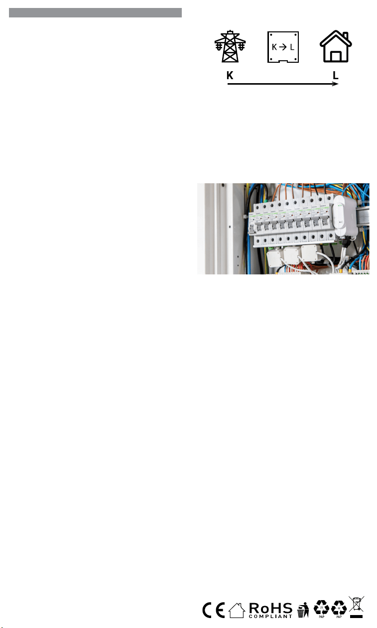
IT
GUIDA PER L’UTENTE E LA SICUREZZA
Contatore di energia Wi-Fi trifase
Leggi prima dell’uso
Questo documento contiene importanti informazioni tecniche e di sicu-
rezzasul dispositivo e sul suo uso e installazione in sicurezza.
⚠ATTENZIONE! Prima di iniziare l’installazione leggere attentamente e
completamente la documentazione allegata. La mancata osservanza delle
procedure consigliate potrebbe portare a malfunzionamenti, pericolo per la
vita o violazione della legge. Allterco Robotics EOOD non è responsabile per
eventuali perdite o danni in caso di installazione o funzionamento errati di
questo dispositivo.
Introduzione al prodotto
Shelly® è una linea di dispositivi innovativi gestiti da microprocessori che
permettono il controllo remoto degli elettrodomestici attraverso un telefo-
no cellulare, un tablet, un PC o un sistema domotico. I dispositivi Shelly®
sono in grado di funzionare autonomamente in una rete Wi-Fi locale o
possono anche essere gestiti attraverso servizi di automazione domesti-
ca cloud. Shelly Cloud è un servizio di questo tipo a cui si può accedere
utilizzando un’applicazione mobile Android o iOS o con qualsiasi browser
internet su https://home.shelly.cloud/. I dispositivi Shelly® sono accessibi-
li, controllati e monitorati a distanza da qualsiasi luogo in cui l’utente abbia
una connettività Internet, purché i dispositivi siano collegati a un router Wi-
Fi e a Internet. I dispositivi Shelly® hanno un’interfaccia web incorporata
accessibile a http://192.168.33.1 nella rete Wi-Fi, creata dal dispositivo in
modalità Access Point, o all’indirizzo URL del dispositivo nella rete Wi-Fi
a cui è connesso. L’interfaccia web incorporata può essere utilizzata per
monitorare e controllare il dispositivo, così come per regolare le sue im-
postazioni.
I dispositivi Shelly® sono in grado di comunicare direttamente con altri
dispositivi Wi-Fi attraverso il protocollo HTTP. Un’API è fornita da Allterco
Robotics EOOD. Per maggiori informazioni, visitare:
https://shelly-api-docs.shelly.cloud/#shelly-family-overview.
I dispositivi Shelly® vengono consegnati con un rmware installato in fabbri-
ca. Se sono necessari aggiornamenti del rmware per mantenere i disposi-
tivi in conformità, compresi gli aggiornamenti di sicurezza, Allterco Robotics
EOOD fornirà gli aggiornamenti gratuitamente attraverso l’interfaccia web in-
corporata del dispositivo o l’applicazione mobile Shelly, dove sono disponibili
le informazioni sulla versione corrente del rmware. La scelta di installare o
meno gli aggiornamenti del rmware del dispositivo è di esclusiva respon-
sabilità dell’utente. Allterco Robotics EOOD non è responsabile per qualsiasi
mancanza di conformità del dispositivo causata dalla mancata installazione
degli aggiornamenti forniti dall’utente in modo tempestivo.
Controlla la tua casa con la tua voce
Tutti i dispositivi Shelly sono compatibili con Amazon Echo e Google
Home. Consulta la nostra guida passo passo su:
https://shelly.cloud/support/compatibility/
Istruzioni per l’installazione
Il misuratore di energia Wi-Fi tripla fase, Shelly 3EM di Allterco Robotics
è destinato ad essere montato accanto agli interruttori, al ne di monito-
rare la potenza elettrica attraverso di esso, indipendente per ogni canale
e controllo di contattori pesanti. Shelly può funzionare come dispositivo
autonomo o come accessorio per un controller di automazione domestica.
Shelly 3EM può misurare l’energia in entrata e in uscita.
• Scopo del controllo: operativo
• Costruzione del controllo: montato in modo indipendente
• Azione di tipo 1.B
• Grado di inquinamento 2
• Tensione di impulso: 4000 V
A seconda di quante fasi vuoi misurare devi collegare il tuo Shelly 3EM
secondo lo schema fornito.
⚠ATTENZIONE! Pericolo di folgorazione. Il montaggio/installazione del
dispositivo alla rete elettrica deve essere eseguito con cautela da un elet-
tricista qualicato.
⚠ATTENZIONE! Pericolo di folgorazione. Ogni modica dei collegamenti
deve essere effettuata dopo essersi assicurati che non ci sia tensione ai
morsetti dell’apparecchio.
⚠ATTENZIONE! Utilizzare l’apparecchio solo con una rete elettrica e con
apparecchi conformi a tutte le norme vigenti. Un cortocircuito nella rete elet-
trica o in qualsiasi apparecchio collegato all’apparecchio può danneggiare
l’apparecchio.
⚠ATTENZIONE! Non collegare l’apparecchio ad apparecchi che superano
il carico massimo indicato!
⚠ATTENZIONE! Collegare l’apparecchio solo nel modo indicato in queste
istruzioni. Qualsiasi altro metodo potrebbe causare danni e/o lesioni.
⚠ATTENZIONE! Non installare il dispositivo in un luogo che possa ba-
gnarsi.
• Il primo passo consiste nell’installare i morsetti di misurazione sui li.
Aprire il trasformatore di corrente con un cacciavite quindi ssarlo sul
cavo di alimentazione desiderato. Eseguire questa operazione per tutti
i trasformatori di corrente, seguire il diagramma del usso di corrente.
ES
GUÍA DE USO Y SEGURIDAD
Medidor de energía Wi-Fi trifásico
Leer antes de usar
Este documento contiene información técnica y de seguridad importante so-
bre el aparato, su uso y su instalación segura.
⚠¡ATENCIÓN! Antes de comenzar la instalación, lea atentamente y por com-
pleto la documentación adjunta. El incumplimiento de los procedimientos reco-
mendados puede provocar un mal funcionamiento, un peligro para su vida o una
violación de la ley. Allterco Robotics no se hace responsable de cualquier pérdida
o daño debido a una instalación o uso inadecuado de este dispositivo.
Resumen del producto
Shelly® es una gama de innovadores dispositivos basados en microprocesa-
dores que permiten controlar a distancia los electrodomésticos a través de un
teléfono móvil, una tableta, un PC o un sistema domótico. Los dispositivos
Shelly® pueden funcionar de forma autónoma en una red Wi-Fi local o también
pueden ser operados por servicios de automatización del hogar a través del
Cloud. Shelly Cloud es un servicio que se puede utilizar a través de la aplicación
móvil Android o iOS, o a través de cualquier navegador web en https://home.
shelly.cloud/. Los dispositivos Shelly® se pueden manejar, controlar y super-
visar a distancia desde cualquier lugar en el que el usuario disponga de una
conexión a Internet, siempre que los dispositivos estén conectados a un router
Wi-Fi y a Internet. Los dispositivos Shelly® tienen una interfaz web integrada a
la que se puede acceder en http://192.168.33.1 dentro de la red Wi-Fi, creada
por el dispositivo en modo de punto de acceso, o en la URL del dispositivo en
la red Wi-Fi a la que está conectado. La interfaz web integrada puede utilizarse
para supervisar y controlar el dispositivo y ajustar su conguración.
Los dispositivos Shelly® pueden comunicarse directamente con otros dispo-
sitivos Wi-Fi a través de HTTP. Allterco Robotics EOOD proporciona una API.
Para más información, visite
https://shelly-api-docs.shelly.cloud/#shelly-family-overview.
Los dispositivos Shelly® vienen con el rmware instalado de fábrica. Si es ne-
cesario actualizar el rmware para que los dispositivos sigan cumpliendo la
normativa, incluidas las actualizaciones de seguridad, Allterco Robotics EOOD
proporcionará las actualizaciones de forma gratuita a través de la interfaz web
integrada en el dispositivo o la aplicación móvil Shelly, donde está disponible
la información de la versión actual del rmware. La decisión de instalar o no
las actualizaciones del rmware del dispositivo es responsabilidad exclusiva
del usuario. Allterco Robotics EOOD no se hace responsable de la falta de con-
formidad del Dispositivo causada por el hecho de que el Usuario no instale
oportunamente las actualizaciones previstas.
Controla tu casa con tu voz
Todos los dispositivos Shelly son compatibles con Amazon Echo y Google
Home. Consulte nuestra guía paso a paso en:
https://shelly.cloud/support/compatibility/.
Instrucciones de instalación
El contador de energía Wi-Fi trifásico Shelly 3EM de Allterco Robotics está di-
señado para ser montado junto a los disyuntores para supervisar la energía
eléctrica que uye a través de ellos, de forma independiente para cada canal
y con control de contactores de alta resistencia. Shelly puede funcionar como
dispositivo autónomo o como accesorio de un controlador domótico. Shelly
3EM puede medir la energía entrante y saliente.
• Finalidad del control: Funcionamiento
• Construcción del control: Montaje independiente
• Acción de tipo 1.B
• Grado de contaminación 2
• Tensión de impulso: 4000 V
En función del número de fases que desee medir, deberá conectar su Shelly
3EM según el esquema suministrado.
⚠¡ATENCIÓN! Peligro de descarga eléctrica. El montaje/instalación del aparato
a la red eléctrica debe ser realizado con cuidado, por un electricista cualicado.
⚠¡ATENCIÓN! Peligro de descarga eléctrica. Cualquier modicación de las
conexiones debe realizarse después de asegurarse de que no hay tensión en
los terminales del Dispositivo.
⚠¡ATENCIÓN! Utilice el dispositivo sólo con una fuente de alimentación y un
equipo que cumplan con todas las normas aplicables. Un cortocircuito en la red
eléctrica o en cualquier dispositivo conectado al aparato puede dañar el aparato.
⚠¡ATENCIÓN! No conecte el aparato a dispositivos que superen la carga máxi-
ma indicada.
⚠¡ATENCIÓN! Conecte el aparato sólo de la manera indicada en estas instruc-
ciones. Cualquier otro método puede causar daños y/o lesiones.
⚠¡ATENCIÓN! No instale el aparato en un lugar donde pueda mojarse.
• El primer paso es instalar las pinzas de medición en los cables. Abra el
transformador de corriente con un destornillador y conéctelo al cable de ali-
mentación deseado. Haga esto para todos los transformadores de corriente,
siguiendo el diagrama en
En la parte inferior de su transformador de núcleo dividido,
verá una flecha que muestra la dirección del flujo de energía.
corriente de núcleo dividido
transformador
• El segundo paso es cablear la fase al terminal respetado del Shelly 3EM. Utili-
PT
GUIA DO UTILIZADOR E DE SEGURANÇA
Medidor Wi-Fi de Energia Trifásico
Leia antes de utilizar
Este documento contém importante informação técnica e de segurança rela-
tiva ao dispositivo, sua utilização segura e instalação.
⚠ATENÇÃO! Antes de iniciar a instalação, por favor leia atentamente e na ínte-
gra a documentação incluída. O incumprimento dos procedimentos recomenda-
dos poderão dar origem a avarias, perigo à sua vida ou violação da lei. A Allterco
Robotics EOOD não se responsabiliza por quaisquer perdas ou danos em caso
de uma incorreta instalação ou incorreta utilização deste dispositivo.
Apresentação do Produto
Shelly® é uma linha de dispositivos inovadores geridos por micro-processador,
que permitem o controlo remote de eletrodomésticos através de telemóvel,
tablet, PC ou sistema de domótica. Os dispositivos Shelly® podem funcionar
isoladamente numa rede Wi-Fi local ou podem também ser operados através
de serviços de domótica em nuvem. Shelly Cloud é um desses serviços que
pode ser acedido usando uma aplicação móvel Android ou iOS, ou com um
qualquer browser de internet em https://home.shelly.cloud/. Os dispositivos
Shelly® podem ser acedidos, controlados e monitorizados remotamente a
partir de qualquer localização onde o Utilizador tiver uma conexão à internet,
desde que os dispositivos estejam conectados a um router Wi-Fi e à Internet.
Os dispositivos Shelly® possuem um Interface Web embutido e acessível em
http://192.168.33.1 na rede Wi-Fi, criada pelo dispositivo em modo Ponto de
Acesso (AP), ou no endereço URL do dispositivo na rede Wi-Fi a que está liga-
do. O Interface Web embutido pode ser usado para monitorizar e controlar o
dispositivo, assim como ajustar as suas congurações.
Os dispositivos Shelly® podem comunicar diretamente com outros dispositi-
vos Wi-Fi através do protocolo HTTP. Uma App é fornecida por Allterco Roboti-
cs EOOD. Para mais informação, por favor visite:
https://shelly-api-docs.shelly.cloud/#shelly-family-overview.
Os dispositivos Shelly® são distribuidos com rmware instalado em fábrica.
Se forem necessárias atualizações ao rmware de forma a manter os dispo-
sitivos em conformidade, incluindo atualizações de segurança, Allterco Robo-
tics EOOD fornecerá as atualizações gratuitamente através do Interface Web
embutido ou da Aplicação Móvel Shelly, onde a informação sobre a versão de
rmware atual se encontra acessível. A escolha em instalar ou não instalar as
atualizações de rmware do Dispositivo é responsabilidade única do utilizador.
Allterco Robotics EOOD não se responsabiliza por qualquer falha na conformi-
dade do Dispositivo causada pela não instalação das atualizações disponíveis
em tempo útil, por parte do Utilizador.
Controle a sua casa com a sua voz
Todos os dispositivos Shelly são compatíveis com Amazon Echo e Google
Home. Por favor consulte o nosso manual passo-a-passo em: https://shelly.
cloud/support/compatibility/
Instruções de Instalação
O Medidor Wi-Fi de Energia Trifásico Shelly 3EM da Allterco Robotics foi de-
senhado para ser montado junto dos disjuntores, de forma a monitorizar a
corrente eléctrica através dos mesmos, para cada canal e cada contactor de
controlo de potência. Shelly pode funcionar como um Dispositivo isolado ou
como acessório de um controlador de domótica. Shelly 3EM consegue medir
energia no sentido de entrada e de saída.
• Finalidade do controlo: Operativo
• Construção do controlo: Montado independentemente
• Ação Tipo 1.B
• Grau de Poluição 2
• Voltagem de impulso: 4000 V
Dependendo do número de fases que quer medir, terá de conetar o seu Shelly
3EM de acordo com o esquema fornecido.
⚠ATENÇÃO! Perigo de eletrocussão. A montagem/instalação do Dispositivo à
rede elétrica deve ser executada com precaução, por um eletricista qualicado.
⚠ATENÇÃO! Perigo de eletrocussão. Qualquer alteração nas ligações só deve
ser executada depois de assegurado de que não existe qualquer voltagem nos
terminais do Dispositivo.
⚠ATENÇÃO! Utilize o Dispositivo apenas com uma rede elétrica e eletrodo-
mésticos que estejam de acordo com os regulamentos aplicáveis. Um curto-cir-
cuito na rede elétrica ou num dos eletrodomésticos conectados poderá danicar
o Dispositivo.
⚠ATENÇÃO! Não conecte o Dispositivo a electrodomésticos se estes excede-
rem a carga máxima permitida.
⚠ATENÇÃO! Conecte o Dispositivo apenas da forma ilustrada nestas instru-
ções. Qualquer outra forma poderá causar danos e/ou acidentes.
⚠ATENÇÃO! Não instale o dispositivo num local que possa car molhado.
• O primeiro passo é ligar os terminais de medição aos cabos condutores. Abra
o transformador de corrente com uma chave de parafusos e acople-o sobre
o cabo de tensão. Proceda da mesma forma com todos os transformadores.
Por favor siga o diagrama do sentido da corrente.
Na parte inferior do seu transformador de núcleo dividido,
você verá uma seta mostrando a direção do fluxo de energia.
corrente Split-Core
transformador
FR
GUIDE D’UTILISATION ET DE SÉCURITÉ
Compteur d’énergie Wi-Fi triphasé
A lire avant utilisation
Ce document contient des informations techniques et de sécurité impor-
tantes concernant l’appareil, son utilisation et son installation en toute sé-
curité.
⚠ATTENTION! Avant de commencer l’installation, veuillez lire attentivement
et complètement la documentation d’accompagnement. Le non-respect des
procédures recommandées peut entraîner un dysfonctionnement, un danger
pour votre vie ou une violation de la loi. Allterco Robotics EOOD n’est pas res-
ponsable des pertes ou des dommages en cas d’installation ou d’utilisation
incorrecte de ce dispositif.
Présentation du produit
Shelly® est une gamme de dispositifs innovants gérés par microprocesseur,
qui permettent de contrôler à distance les appareils électriques par le biais
d’un téléphone mobile, d’une tablette, d’un PC ou d’un système domotique.
Les dispositifs Shelly® peuvent fonctionner de manière autonome sur un
réseau local Wi-Fi ou ils peuvent également être exploités par des services
domotiques via Cloud. Shelly Cloud est un service utilisable via l’application
mobile Android ou iOS, ou via n’importe quel navigateur Internet sur https://
home.shelly.cloud/. Les dispositifs Shelly® peuvent être utilisés, contrôlés
et surveillés à distance depuis n’importe quel endroit où l’utilisateur dispose
d’une connexion Internet, à condition que les dispositifs soient connectés à
un routeur Wi-Fi et à Internet. Les dispositifs Shelly® ont une interface Web
intégrée accessible sur http://192.168.33.1 au sein du réseau Wi-Fi, créé par
le dispositif en mode point d’accès, ou à l’adresse URL du dispositif sur le ré-
seau Wi-Fi auquel il est connecté. L’interface Web intégrée peut être utilisée
pour surveiller et contrôler le dispositif, ainsi que pour ajuster ses paramètres.
Les dispositifs Shelly® peuvent communiquer directement avec d’autres dis-
positifs Wi-Fi par le biais du protocole HTTP. Une API est fournie par Allterco
Robotics EOOD. Pour plus d’informations, veuillez visiter :
https://shelly-api-docs.shelly.cloud/#shelly-family-overview.
Les dispositifs Shelly® sont livrés avec un micrologiciel installé en usine. Si
des mises à jour du micrologiciel sont nécessaires pour maintenir les dispo-
sitifs en conformité, y compris des mises à jour de sécurité, Allterco Robotics
EOOD fournira les mises à jour gratuitement via l’interface Web intégrée au dis-
positif ou l’application mobile Shelly, où les informations sur la version actuelle
du micrologiciel sont disponibles. Le choix d’installer ou non les mises à jour
du micrologiciel du dispositif relève de la seule responsabilité de l’Utilisateur.
Allterco Robotics EOOD ne sera pas responsable de tout manque de confor-
mité du Dispositif causé par le fait que l’Utilisateur n’a pas installé les mises à
jour fournies en temps voulu.
Contrôlez votre maison avec votre voix
Tous les dispositifs Shelly sont compatibles avec Amazon Echo et Google
Home. Veuillez consulter notre guide étape par étape sur :
https://shelly.cloud/support/compatibility/.
Instructions d’installation
Le compteur d’énergie Wi-Fi triphasé Shelly 3EM d’Allterco Robotics est desti-
né à être monté à côté des disjoncteurs, an de surveiller l’énergie électrique
qui y passe, indépendamment pour chaque canal et avec un contrôle des
contacteurs à usage intensif. Shelly peut fonctionner comme un dispositif
autonome ou comme accessoire d’un contrôleur domotique. Shelly 3EM peut
mesurer l’énergie entrante et sortante.
• Objectif de la commande : Fonctionnement
• Construction de la commande : Montée de façon indépendante
• Type 1.B Action
• Degré de pollution 2
• Tension d’impulsion : 4000 V
En fonction du nombre de phases que vous souhaitez mesurer, vous devez
connecter votre Shelly 3EM selon le schéma fourni.
⚠ATTENTION! Danger d’électrocution. Le montage/installation de l’Appareil
sur le réseau électrique doit être effectué avec prudence, par un électricien
qualié.
⚠ATTENTION! Danger d’électrocution. Chaque modication des connexions
doit être effectuée après s’être assuré de l’absence de tension aux bornes du
Dispositif.
⚠ATTENTION! N’utilisez l’Appareil qu’avec un réseau électrique et des appa-
reils conformes à toutes les réglementations applicables. Un court-circuit sur
le réseau électrique ou tout appareil connecté à l’Appareil peut endommager
l’Appareil.
⚠ATTENTION! Ne connectez pas l’Appareil à des appareils dépassant la
charge maximale indiquée !
⚠ATTENTION! Connectez l’Appareil uniquement de la manière indiquée dans
ces instructions. Toute autre méthode pourrait causer des dommages et/ou
des blessures.
⚠ATTENTION! N’installez pas l’appareil à un endroit où il est possible qu’il
se mouille.
• La première étape consiste à installer les pinces de mesure sur les ls.
Ouvrez le transformateur de courant avec un tournevis puis xez-le sur le
câble d’alimentation souhaité. Faites ceci pour tous les transformateurs de
courant, suivez le schéma de
Nella parte inferiore del trasformatore a nucleo diviso, vedrai
una freccia che mostra la direzione del flusso di energia.
corrente split core
trasformatore
• Il secondo passo consiste nel collegare la fase al terminale rispettato
su Shelly 3EM. Si prega di utilizzare il lo e serrarlo bene con la vite sui
terminali Shelly.
• L’ultimo passaggio consiste nel collegare l’alimentazione al dispositivo. Si
prega di collegare il cavo di alimentazione al terminale rispettato.
Devi seguire uno dei diagrammi proposti:
Schema di cablaggio trifase – Fig.1
Cablaggio bifase (US) – Fig.2
Cablaggio di misurazione dell’energia solare monofase + separato – Fig.3
Cablaggio monofase no a 3 circuiti diversi – Fig.4
⚠ATTENZIONE! Collegare i trasformatori di corrente di conseguenza per
ogni canale! Ogni trasformatore di corrente è marcato e calibrato per il ri-
spettivo ingresso del Dispositivo. Qualsiasi collegamento improprio porterà
a misurazioni e visualizzazioni errate del dispositivo.
Inclusione iniziale
Se si sceglie di utilizzare il dispositivo con l’applicazione mobile Shelly
Cloud e il servizio Shelly Cloud, le istruzioni su come collegare il dispositivo
al Cloud e controllarlo attraverso l’App Shelly si trovano nella “Guida App”
www.shelly.cloud/app-guide
. L’applicazione mobile Shelly e il servizio
Shelly Cloud non sono condizioni per il corretto funzionamento del Disposi-
tivo. Questo Dispositivo può essere utilizzato con vari altri servizi e applica-
zioni di automazione domestica.
⚠ATTENZIONE! Non permettere ai bambini di giocare con i pulsanti/inter-
ruttori collegati al Dispositivo. Tenere i dispositivi per il controllo remoto di
Shelly (telefoni cellulari, tablet, PC) lontano dai bambini.
Speciche
• Alimentazione: 110-240 VAC, 50/60Hz
• Misurazione massima per canale: 120 A
• Carico massimo relè: 10 A / 240 VAC
• Temperatura di esercizio: da -20°C a 40°C
• Potenza massima in uscita RF: 10.82 dBm
• Protocollo radio: Wi-Fi 802.11 b/g/n
• Frequenza: 2412-2472 Hz; (Massimo 2483,5 MHz)
• Gamma operativa (a seconda della costruzione locale):
- no a 50 m all’aperto
- no a 30 m in interni
• Dimensioni (AxPxL): 73x57x22 mm
• Consumo elettrico: < 1W
• MQTT: SÌ
• CoAP: SÌ
• Webhooks (azioni URL): 8 con 5 URL per hook
• Pianicazioni: 20
Rilevamento furto di energia
Per rendere disponibile questa funzione, potrebbe essere necessario ag-
giornare il rmware del dispositivo. Con un trasformatore di corrente a nu-
cleo diviso aggiuntivo, collegato al terminale IN-IN+ di Shelly 3EM, potresti
ricevere una notica in caso di furto o dispersione di energia. Si prega di
seguire gli schemi elettrici di g. 1 e 2, a seconda dell’applicazione.
Dichiarazione di conformità
Con la presente, Allterco Robotics EOOD dichiara che il tipo di apparecchiatura
radio Shelly 3EM è conforme alla Direttiva 2014/53/UE, 2014/35/UE, 2014/30/
UE, 2011/65/UE. Il testo completo della dichiarazione di conformità UE è di-
sponibile al seguente indirizzo Internet: https://shelly.link/3em_DoC
Produttore: Allterco Robotics EOOD
Indirizzo: Bulgaria, Soa, 1407, 103 Cherni vrah Blvd.
Tel.: +359 2 988 7435
E-mail: support@shelly.cloud Web: http://www.shelly.cloud
Le modiche ai dati di contatto sono pubblicate dal Produttore all’indirizzo
il sito uciale del Dispositivo http://www.shelly.cloud
Tutti i diritti sul marchio Shelly® e altri diritti intellettuali associati a questo
dispositivo appartengono a Allterco Robotics EOOD.
za cable y apriétalo bien con los tornillos de los terminales Shelly.
• El último paso es conectar la fuente de alimentación al dispositivo. Conecte El
cable de alimentación al terminal correspondiente.
Diagrama de cableado trifásico - Fig. 1
Cableado bifásico (EE.UU.) - Fig.2
Cableado monofásico + medición separada de la energía solar - Fig.3
Cableado monofásico de hasta 3 circuitos diferentes - Fig.4
⚠¡CUIDADO! ¡Conecte los transformadores de corriente de forma adecuada
para cada canal! Cada transformador de corriente está marcado y calibrado para
la entrada respectiva del aparato. Cualquier conexión incorrecta dará lugar a una
medición y visualización incorrectas del Dispositivo.
Inclusión inicial
Si decide utilizar el Dispositivo con la aplicación móvil Shelly Cloud y el ser-
vicio Shelly Cloud, las instrucciones para conectar el Dispositivo al Cloud
y controlarlo a través de la App Shelly se encuentran en la “Guía de la App”
www.shelly.cloud/app-guide
. La aplicación móvil Shelly y el servicio Shelly
Cloud no son condiciones para el buen funcionamiento del Dispositivo. Este
dispositivo puede utilizarse con otros servicios y aplicaciones de domótica.
⚠¡ATENCIÓN! No permita que los niños jueguen con los botones/interrupto-
res conectados al aparato. Mantenga los dispositivos que permiten el control
remoto de Shelly (teléfonos móviles, tabletas, ordenadores) fuera del alcance
de los niños.
Características:
• Alimentación: 110-240 VAC, 50/60Hz
• Máxima medición por canal: 120 A
• Carga máxima del relé: 10 A / 240 VCA
• Temperatura de funcionamiento : -20°C a 40°C
• Potencia máxima de salida de RF: 10.82 dBm
• Protocolo de radio: Wi-Fi 802.11 b/g/n
• Frecuencia: 2412-2472 МHz; (máx. 2483,5 MHz)
• Distancia operativa (dependiendo de la construcción local):
- hasta 50 m en el exterior
- hasta 30 m en interior
• Dimensiones (HxAxA): 73x57x22 mm
• Consumo de energía: < 1W
• MQTT: SÍ
• CoAP: SÍ
• Webhooks (acciones URL): 8 con 5 URLs por hook
• Agendamentos: 20
Detección de robos de energía
Para que esta función esté disponible, es posible que tengas que actualizar el
rmware de tu dispositivo. Con un transformador de corriente de núcleo divi-
dido adicional conectado al terminal IN- IN+ del Shelly 3EM, puede recibir una
noticación, si hay un robo de energía o una fuga. Por favor, siga los diagramas
de cableado de las imágenes 1 y 2, dependiendo de su aplicación.
Declaración de conformidad
Allterco Robotics EOOD declara que el equipo de radio Shelly 3EM cumple con
las directivas 2014/53/UE, 2014/35/UE, 2014/30/UE, 2011/65/ UE. El texto
completo de la declaración de conformidad de la UE está disponible en la si-
guiente dirección web:
https://shelly.link/3em_DoC
Fabricante: Allterco Robotics EOOD
Dirección: Bulgaria, Soa, 1407, 103 Cherni vrah Blvd.
Tel.: +359 2 988 7435
Correo electrónico: support@shelly.cloud
Web: http://www.shelly.cloud
Los cambios en los datos de contacto son publicados por el fabricante en el
sitio web ocial del dispositivo http://www.shelly.cloud
Todos los derechos de la marca Shelly® y otros derechos de propiedad intelec-
tual asociados a este dispositivo pertenecen a Allterco Robotics EOOD.
• O segundo passo é conectar a fase ao respetivo terminal no Shelly 3EM. Por
favor utilize o e aperte bem os parafusos nos terminais do Shelly.
• O último passo é conectar a alimentação ao dispositivo. Por favor conecte o
cabo de alimentação ao respetivo terminal.
Esquema de ligação trifásica - Fig.1
Esquema de ligação difásica (US) - Fig.1
Esquema de ligação monofásica + Medição independente de painel de energia
solar - Fig.3
Esquema de ligação monofásica para até 3 circuitos independentes - Fig.4
⚠ATENÇÃO! Conecte os transformadores de corrente de acordo com cada
canal. Cada transformador de corrente está identicado e calibrado para a res-
pectiva entrada do Dispositivo. Qualquer conecção indevida dará origem a uma
incorrecta medição e visualização.
Inclusão Inicial
Se escolher usar o Dispositivo com a aplicação móvel Shelly Cloud e o servi-
ço Shelly Cloud, instruções em como conectar o Dispositivo à Cloud e como
controlá-lo através da App Shelly, podem ser encontradas no “Guia da App”
www.shelly.cloud/app-guide
. A Shelly Mobile Application e o serviço Shelly
Cloud não são condições únicas para o funcionamento adequado do disposi-
tivo. Este Dispositivo pode ser utilizado com variadas aplicações e serviços
de domótica.
⚠¡ATENCIÓN! No permita que los niños jueguen con los botones/interrupto-
res conectados al aparato. Mantenga los dispositivos que permiten el control
remoto de Shelly (teléfonos móviles, tabletas, ordenadores) fuera del alcance
de los niños.
Especicações
• Fonte de alimentação: 110-240 VAC, 50/60Hz
• Medição máxima por canal: 120 A
• Carga máxima da relé: 10 A / 240 VCA
• Temperatura de funcionamento: -20°C até 40°C
• Potência máx. de saída RF: 10.82 dBm
• Protocolo de rádio: Wi-Fi 802.11 b/g/n
• Frequência: 2412-2472 МHz; (Máx. 2483.5 MHz)
• Alcance de funcionamento (dependendo da construção local):
- até 50 m ao ar livre
- até 30 m no interior
• Dimensões (AxLxP): 73x57x22 mm
• Consumo elétrico: < 1W
• MQTT: Sim
• CoAP: Sim
• Webhooks (acções de URL): 8 com 5 URLs por hook
• Horarios: 20
Deteção de Furto de Energia
Para ter esta funcionalidade disponível, poderá ter de actualizar o rmware do
seu dispositivo. Com um transformador de corrente Split-Core adicional, co-
nectado aos terminais IN- IN+ do Shelly 3EM, poderá receber uma noticação
se existir furto ou perda de energia. Por favor siga os diagramas de ligação na
g. 1 e 2, dependendo da sua aplicação.
Declaração de conformidade
Alterco Robotics EOOD declara, por este meio, que o tipo de equipamento
Shelly 3EM está em conformidade com as Directivas 2014/53/ EU, 2014/35/
EU, 2014/30/EU, 2011/65/EU. O texto completo da declaração de conformida-
de da UE está disponível no seguinte endereço de internet:
https://shelly.link/3em_DoC
Fabricante: Allterco Robotics EOOD
Endereço: Soa, 1407, 103 Cherni vrah Blvd. Bulgária
Tel.: +359 2 988 7435
E-mail: support@shelly.cloud
Web: https://www.shelly.cloud
Quaisquer alterações aos dados de contato serão publicados pelo Fabricante
no website ocial do Dispositivo https://www.shelly.cloud
Todos os direito da marca Shelly®, e quaisquer outros diretios intelectuais as-
sociados a este Dispositivo pertencem à Allterco Robotics EOOD.
Au bas de votre transformateur à noyau divisé, vous verrez
une flèche indiquant la direction du flux d'énergie.
courant de noyau divisé
transformateur
• La deuxième étape consiste à câbler la phase à la borne respectée du Shelly
3EM. Utilisez du l et serrez-le bien avec les vis sur les bornes Shelly.
• La dernière étape consiste à connecter l’alimentation à l’appareil. Connectez
le l d’alimentation à la borne correspondante.
Vous devez suivre l’un des schémas proposés :
Schéma de câblage triphasé - Img.1
Câblage 2 phases (US) - Img.2
Câblage 1 phase + mesure séparée de l’énergie solaire - Img.3
Câblage monophasé jusqu’à 3 circuits différents - Img.4
⚠ATTENTION! Connectez les transformateurs de courant en conséquence
pour chaque canal ! Chaque transformateur de courant est marqué et calibré
pour l’entrée respective de l’Appareil. Toute connexion incorrecte entraînera une
mesure et une visualisation incorrectes de l’appareil.
Inclusion initiale
Si vous choisissez d’utiliser l’Appareil avec l’application mobile Shelly Cloud
et le service Shelly Cloud, les instructions pour connecter l’Appareil au
Cloud et le contrôler via l’App Shelly se trouvent dans le “ Guide de l’App “
www.shelly.cloud/app-guide
. L’application mobile Shelly et le service Shelly
Cloud ne sont pas des conditions au bon fonctionnement de l’Appareil. Cet Ap-
pareil peut être utilisé avec divers autres services et applications domotiques.
⚠ATTENTION! Ne laissez pas les enfants jouer avec les boutons/interrupteurs
connectés à l’Appareil. Gardez les Dispositifs permettant de contrôler Shelly à
distance (téléphones mobiles, tablettes, PC) hors de portée des enfants.
Caractéristiques:
• Alimentation électrique : 110-240 VAC, 50/60Hz
• Mesure maximale par canal : 120 A
• Charge maximale du relais : 10 A / 240 VCA
• Température de fonctionnement : -20°C à 40°C
• Puissance de sortie RF maximale: 10.82 dBm
• Protocole radio : Wi-Fi 802.11 b/g/n
• Fréquence : 2412-2472 МHz ; (Max. 2483.5 MHz)
• Distance opérationnelle (en fonction de la construction locale) :
-jusqu’à 50 m en extérieur
-jusqu’à 30 m à l’intérieur
• Dimensions (HxLxL) : 73x57x22 mm
• Consommation électrique : < 1W
• MQTT : Oui
• CoAP : Oui
• Webhooks (actions URL) : 8 avec 5 URL par crochet
• Planications : 20
Détection de vol d’énergie
Pour que cette fonction soit disponible, vous devrez peut-être mettre à jour le
micrologiciel de votre appareil. Avec un transformateur de courant supplémen-
taire à noyau divisé, connecté à la borne IN- IN+ du Shelly 3EM, vous pouvez
recevoir une notication, s’il y a un vol ou une fuite d’énergie. Veuillez suivre
les schémas de câblage des images 1 et 2, en fonction de votre application.
Déclaration de conformité
Par la présente, Allterco Robotics EOOD déclare que l’équipement radio
de type Shelly 3EM est conforme à la directive 2014/53/EU, 2014/35/ EU,
2014/30/EU, 2011/65/EU. Le texte complet de la déclaration de conformité
UE est disponible à l’adresse internet suivante :
https://shelly.link/3em_DoC
Fabricant: Allterco Robotics EOOD
Adresse: Bulgarie, Soa, 1407, 103 Cherni vrah Blvd.
Tél: +359 2 988 7435
Courriel: support@shelly.cloud Web: http://www.shelly.cloud
Les modications des données de contact sont publiées par le fabricant sur le
site ociel du dispositif http://www.shelly.cloud
Tous les droits sur la marque Shelly® et les autres droits intellectuels associés
à ce dispositif appartiennent à Allterco Robotics EOOD.
50/2022
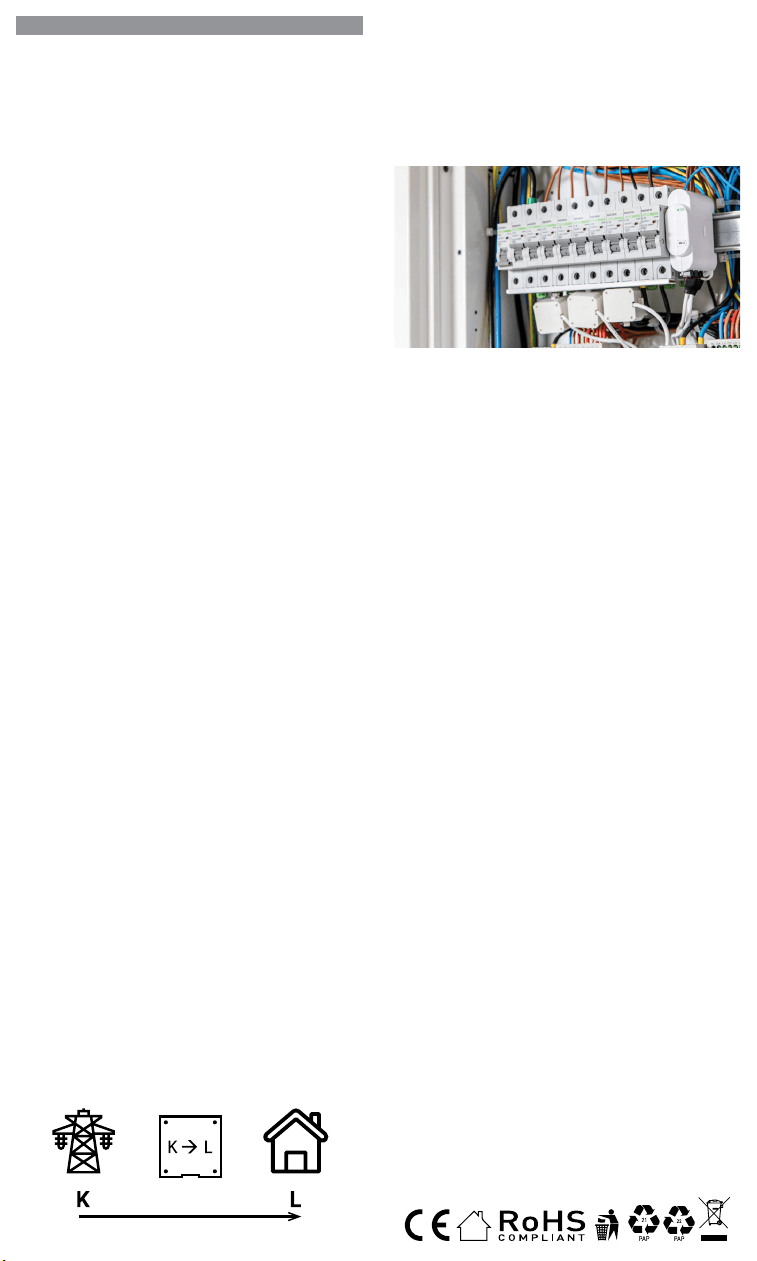
IT
GUIDA PER L’UTENTE E LA SICUREZZA
Contatore di energia Wi-Fi trifase
Leggi prima dell’uso
Questo documento contiene importanti informazioni tecniche e di sicu-
rezzasul dispositivo e sul suo uso e installazione in sicurezza.
⚠ATTENZIONE! Prima di iniziare l’installazione leggere attentamente e
completamente la documentazione allegata. La mancata osservanza delle
procedure consigliate potrebbe portare a malfunzionamenti, pericolo per la
vita o violazione della legge. Allterco Robotics EOOD non è responsabile per
eventuali perdite o danni in caso di installazione o funzionamento errati di
questo dispositivo.
Introduzione al prodotto
Shelly® è una linea di dispositivi innovativi gestiti da microprocessori che
permettono il controllo remoto degli elettrodomestici attraverso un telefo-
no cellulare, un tablet, un PC o un sistema domotico. I dispositivi Shelly®
sono in grado di funzionare autonomamente in una rete Wi-Fi locale o
possono anche essere gestiti attraverso servizi di automazione domesti-
ca cloud. Shelly Cloud è un servizio di questo tipo a cui si può accedere
utilizzando un’applicazione mobile Android o iOS o con qualsiasi browser
internet su https://home.shelly.cloud/. I dispositivi Shelly® sono accessibi-
li, controllati e monitorati a distanza da qualsiasi luogo in cui l’utente abbia
una connettività Internet, purché i dispositivi siano collegati a un router Wi-
Fi e a Internet. I dispositivi Shelly® hanno un’interfaccia web incorporata
accessibile a http://192.168.33.1 nella rete Wi-Fi, creata dal dispositivo in
modalità Access Point, o all’indirizzo URL del dispositivo nella rete Wi-Fi
a cui è connesso. L’interfaccia web incorporata può essere utilizzata per
monitorare e controllare il dispositivo, così come per regolare le sue im-
postazioni.
I dispositivi Shelly® sono in grado di comunicare direttamente con altri
dispositivi Wi-Fi attraverso il protocollo HTTP. Un’API è fornita da Allterco
Robotics EOOD. Per maggiori informazioni, visitare:
https://shelly-api-docs.shelly.cloud/#shelly-family-overview.
I dispositivi Shelly® vengono consegnati con un rmware installato in fabbri-
ca. Se sono necessari aggiornamenti del rmware per mantenere i disposi-
tivi in conformità, compresi gli aggiornamenti di sicurezza, Allterco Robotics
EOOD fornirà gli aggiornamenti gratuitamente attraverso l’interfaccia web in-
corporata del dispositivo o l’applicazione mobile Shelly, dove sono disponibili
le informazioni sulla versione corrente del rmware. La scelta di installare o
meno gli aggiornamenti del rmware del dispositivo è di esclusiva respon-
sabilità dell’utente. Allterco Robotics EOOD non è responsabile per qualsiasi
mancanza di conformità del dispositivo causata dalla mancata installazione
degli aggiornamenti forniti dall’utente in modo tempestivo.
Controlla la tua casa con la tua voce
Tutti i dispositivi Shelly sono compatibili con Amazon Echo e Google
Home. Consulta la nostra guida passo passo su:
https://shelly.cloud/support/compatibility/
Istruzioni per l’installazione
Il misuratore di energia Wi-Fi tripla fase, Shelly 3EM di Allterco Robotics
è destinato ad essere montato accanto agli interruttori, al ne di monito-
rare la potenza elettrica attraverso di esso, indipendente per ogni canale
e controllo di contattori pesanti. Shelly può funzionare come dispositivo
autonomo o come accessorio per un controller di automazione domestica.
Shelly 3EM può misurare l’energia in entrata e in uscita.
• Scopo del controllo: operativo
• Costruzione del controllo: montato in modo indipendente
• Azione di tipo 1.B
• Grado di inquinamento 2
• Tensione di impulso: 4000 V
A seconda di quante fasi vuoi misurare devi collegare il tuo Shelly 3EM
secondo lo schema fornito.
⚠ATTENZIONE! Pericolo di folgorazione. Il montaggio/installazione del
dispositivo alla rete elettrica deve essere eseguito con cautela da un elet-
tricista qualicato.
⚠ATTENZIONE! Pericolo di folgorazione. Ogni modica dei collegamenti
deve essere effettuata dopo essersi assicurati che non ci sia tensione ai
morsetti dell’apparecchio.
⚠ATTENZIONE! Utilizzare l’apparecchio solo con una rete elettrica e con
apparecchi conformi a tutte le norme vigenti. Un cortocircuito nella rete elet-
trica o in qualsiasi apparecchio collegato all’apparecchio può danneggiare
l’apparecchio.
⚠ATTENZIONE! Non collegare l’apparecchio ad apparecchi che superano
il carico massimo indicato!
⚠ATTENZIONE! Collegare l’apparecchio solo nel modo indicato in queste
istruzioni. Qualsiasi altro metodo potrebbe causare danni e/o lesioni.
⚠ATTENZIONE! Non installare il dispositivo in un luogo che possa ba-
gnarsi.
• Il primo passo consiste nell’installare i morsetti di misurazione sui li.
Aprire il trasformatore di corrente con un cacciavite quindi ssarlo sul
cavo di alimentazione desiderato. Eseguire questa operazione per tutti
i trasformatori di corrente, seguire il diagramma del usso di corrente.
ES
GUÍA DE USO Y SEGURIDAD
Medidor de energía Wi-Fi trifásico
Leer antes de usar
Este documento contiene información técnica y de seguridad importante so-
bre el aparato, su uso y su instalación segura.
⚠¡ATENCIÓN! Antes de comenzar la instalación, lea atentamente y por com-
pleto la documentación adjunta. El incumplimiento de los procedimientos reco-
mendados puede provocar un mal funcionamiento, un peligro para su vida o una
violación de la ley. Allterco Robotics no se hace responsable de cualquier pérdida
o daño debido a una instalación o uso inadecuado de este dispositivo.
Resumen del producto
Shelly® es una gama de innovadores dispositivos basados en microprocesa-
dores que permiten controlar a distancia los electrodomésticos a través de un
teléfono móvil, una tableta, un PC o un sistema domótico. Los dispositivos
Shelly® pueden funcionar de forma autónoma en una red Wi-Fi local o también
pueden ser operados por servicios de automatización del hogar a través del
Cloud. Shelly Cloud es un servicio que se puede utilizar a través de la aplicación
móvil Android o iOS, o a través de cualquier navegador web en https://home.
shelly.cloud/. Los dispositivos Shelly® se pueden manejar, controlar y super-
visar a distancia desde cualquier lugar en el que el usuario disponga de una
conexión a Internet, siempre que los dispositivos estén conectados a un router
Wi-Fi y a Internet. Los dispositivos Shelly® tienen una interfaz web integrada a
la que se puede acceder en http://192.168.33.1 dentro de la red Wi-Fi, creada
por el dispositivo en modo de punto de acceso, o en la URL del dispositivo en
la red Wi-Fi a la que está conectado. La interfaz web integrada puede utilizarse
para supervisar y controlar el dispositivo y ajustar su conguración.
Los dispositivos Shelly® pueden comunicarse directamente con otros dispo-
sitivos Wi-Fi a través de HTTP. Allterco Robotics EOOD proporciona una API.
Para más información, visite
https://shelly-api-docs.shelly.cloud/#shelly-family-overview.
Los dispositivos Shelly® vienen con el rmware instalado de fábrica. Si es ne-
cesario actualizar el rmware para que los dispositivos sigan cumpliendo la
normativa, incluidas las actualizaciones de seguridad, Allterco Robotics EOOD
proporcionará las actualizaciones de forma gratuita a través de la interfaz web
integrada en el dispositivo o la aplicación móvil Shelly, donde está disponible
la información de la versión actual del rmware. La decisión de instalar o no
las actualizaciones del rmware del dispositivo es responsabilidad exclusiva
del usuario. Allterco Robotics EOOD no se hace responsable de la falta de con-
formidad del Dispositivo causada por el hecho de que el Usuario no instale
oportunamente las actualizaciones previstas.
Controla tu casa con tu voz
Todos los dispositivos Shelly son compatibles con Amazon Echo y Google
Home. Consulte nuestra guía paso a paso en:
https://shelly.cloud/support/compatibility/.
Instrucciones de instalación
El contador de energía Wi-Fi trifásico Shelly 3EM de Allterco Robotics está di-
señado para ser montado junto a los disyuntores para supervisar la energía
eléctrica que uye a través de ellos, de forma independiente para cada canal
y con control de contactores de alta resistencia. Shelly puede funcionar como
dispositivo autónomo o como accesorio de un controlador domótico. Shelly
3EM puede medir la energía entrante y saliente.
• Finalidad del control: Funcionamiento
• Construcción del control: Montaje independiente
• Acción de tipo 1.B
• Grado de contaminación 2
• Tensión de impulso: 4000 V
En función del número de fases que desee medir, deberá conectar su Shelly
3EM según el esquema suministrado.
⚠¡ATENCIÓN! Peligro de descarga eléctrica. El montaje/instalación del aparato
a la red eléctrica debe ser realizado con cuidado, por un electricista cualicado.
⚠¡ATENCIÓN! Peligro de descarga eléctrica. Cualquier modicación de las
conexiones debe realizarse después de asegurarse de que no hay tensión en
los terminales del Dispositivo.
⚠¡ATENCIÓN! Utilice el dispositivo sólo con una fuente de alimentación y un
equipo que cumplan con todas las normas aplicables. Un cortocircuito en la red
eléctrica o en cualquier dispositivo conectado al aparato puede dañar el aparato.
⚠¡ATENCIÓN! No conecte el aparato a dispositivos que superen la carga máxi-
ma indicada.
⚠¡ATENCIÓN! Conecte el aparato sólo de la manera indicada en estas instruc-
ciones. Cualquier otro método puede causar daños y/o lesiones.
⚠¡ATENCIÓN! No instale el aparato en un lugar donde pueda mojarse.
• El primer paso es instalar las pinzas de medición en los cables. Abra el
transformador de corriente con un destornillador y conéctelo al cable de ali-
mentación deseado. Haga esto para todos los transformadores de corriente,
siguiendo el diagrama en
En la parte inferior de su transformador de núcleo dividido,
verá una flecha que muestra la dirección del flujo de energía.
corriente de núcleo dividido
transformador
• El segundo paso es cablear la fase al terminal respetado del Shelly 3EM. Utili-
PT
GUIA DO UTILIZADOR E DE SEGURANÇA
Medidor Wi-Fi de Energia Trifásico
Leia antes de utilizar
Este documento contém importante informação técnica e de segurança rela-
tiva ao dispositivo, sua utilização segura e instalação.
⚠ATENÇÃO! Antes de iniciar a instalação, por favor leia atentamente e na ínte-
gra a documentação incluída. O incumprimento dos procedimentos recomenda-
dos poderão dar origem a avarias, perigo à sua vida ou violação da lei. A Allterco
Robotics EOOD não se responsabiliza por quaisquer perdas ou danos em caso
de uma incorreta instalação ou incorreta utilização deste dispositivo.
Apresentação do Produto
Shelly® é uma linha de dispositivos inovadores geridos por micro-processador,
que permitem o controlo remote de eletrodomésticos através de telemóvel,
tablet, PC ou sistema de domótica. Os dispositivos Shelly® podem funcionar
isoladamente numa rede Wi-Fi local ou podem também ser operados através
de serviços de domótica em nuvem. Shelly Cloud é um desses serviços que
pode ser acedido usando uma aplicação móvel Android ou iOS, ou com um
qualquer browser de internet em https://home.shelly.cloud/. Os dispositivos
Shelly® podem ser acedidos, controlados e monitorizados remotamente a
partir de qualquer localização onde o Utilizador tiver uma conexão à internet,
desde que os dispositivos estejam conectados a um router Wi-Fi e à Internet.
Os dispositivos Shelly® possuem um Interface Web embutido e acessível em
http://192.168.33.1 na rede Wi-Fi, criada pelo dispositivo em modo Ponto de
Acesso (AP), ou no endereço URL do dispositivo na rede Wi-Fi a que está liga-
do. O Interface Web embutido pode ser usado para monitorizar e controlar o
dispositivo, assim como ajustar as suas congurações.
Os dispositivos Shelly® podem comunicar diretamente com outros dispositi-
vos Wi-Fi através do protocolo HTTP. Uma App é fornecida por Allterco Roboti-
cs EOOD. Para mais informação, por favor visite:
https://shelly-api-docs.shelly.cloud/#shelly-family-overview.
Os dispositivos Shelly® são distribuidos com rmware instalado em fábrica.
Se forem necessárias atualizações ao rmware de forma a manter os dispo-
sitivos em conformidade, incluindo atualizações de segurança, Allterco Robo-
tics EOOD fornecerá as atualizações gratuitamente através do Interface Web
embutido ou da Aplicação Móvel Shelly, onde a informação sobre a versão de
rmware atual se encontra acessível. A escolha em instalar ou não instalar as
atualizações de rmware do Dispositivo é responsabilidade única do utilizador.
Allterco Robotics EOOD não se responsabiliza por qualquer falha na conformi-
dade do Dispositivo causada pela não instalação das atualizações disponíveis
em tempo útil, por parte do Utilizador.
Controle a sua casa com a sua voz
Todos os dispositivos Shelly são compatíveis com Amazon Echo e Google
Home. Por favor consulte o nosso manual passo-a-passo em: https://shelly.
cloud/support/compatibility/
Instruções de Instalação
O Medidor Wi-Fi de Energia Trifásico Shelly 3EM da Allterco Robotics foi de-
senhado para ser montado junto dos disjuntores, de forma a monitorizar a
corrente eléctrica através dos mesmos, para cada canal e cada contactor de
controlo de potência. Shelly pode funcionar como um Dispositivo isolado ou
como acessório de um controlador de domótica. Shelly 3EM consegue medir
energia no sentido de entrada e de saída.
• Finalidade do controlo: Operativo
• Construção do controlo: Montado independentemente
• Ação Tipo 1.B
• Grau de Poluição 2
• Voltagem de impulso: 4000 V
Dependendo do número de fases que quer medir, terá de conetar o seu Shelly
3EM de acordo com o esquema fornecido.
⚠ATENÇÃO! Perigo de eletrocussão. A montagem/instalação do Dispositivo à
rede elétrica deve ser executada com precaução, por um eletricista qualicado.
⚠ATENÇÃO! Perigo de eletrocussão. Qualquer alteração nas ligações só deve
ser executada depois de assegurado de que não existe qualquer voltagem nos
terminais do Dispositivo.
⚠ATENÇÃO! Utilize o Dispositivo apenas com uma rede elétrica e eletrodo-
mésticos que estejam de acordo com os regulamentos aplicáveis. Um curto-cir-
cuito na rede elétrica ou num dos eletrodomésticos conectados poderá danicar
o Dispositivo.
⚠ATENÇÃO! Não conecte o Dispositivo a electrodomésticos se estes excede-
rem a carga máxima permitida.
⚠ATENÇÃO! Conecte o Dispositivo apenas da forma ilustrada nestas instru-
ções. Qualquer outra forma poderá causar danos e/ou acidentes.
⚠ATENÇÃO! Não instale o dispositivo num local que possa car molhado.
• O primeiro passo é ligar os terminais de medição aos cabos condutores. Abra
o transformador de corrente com uma chave de parafusos e acople-o sobre
o cabo de tensão. Proceda da mesma forma com todos os transformadores.
Por favor siga o diagrama do sentido da corrente.
Na parte inferior do seu transformador de núcleo dividido,
você verá uma seta mostrando a direção do fluxo de energia.
corrente Split-Core
transformador
FR
GUIDE D’UTILISATION ET DE SÉCURITÉ
Compteur d’énergie Wi-Fi triphasé
A lire avant utilisation
Ce document contient des informations techniques et de sécurité impor-
tantes concernant l’appareil, son utilisation et son installation en toute sé-
curité.
⚠ATTENTION! Avant de commencer l’installation, veuillez lire attentivement
et complètement la documentation d’accompagnement. Le non-respect des
procédures recommandées peut entraîner un dysfonctionnement, un danger
pour votre vie ou une violation de la loi. Allterco Robotics EOOD n’est pas res-
ponsable des pertes ou des dommages en cas d’installation ou d’utilisation
incorrecte de ce dispositif.
Présentation du produit
Shelly® est une gamme de dispositifs innovants gérés par microprocesseur,
qui permettent de contrôler à distance les appareils électriques par le biais
d’un téléphone mobile, d’une tablette, d’un PC ou d’un système domotique.
Les dispositifs Shelly® peuvent fonctionner de manière autonome sur un
réseau local Wi-Fi ou ils peuvent également être exploités par des services
domotiques via Cloud. Shelly Cloud est un service utilisable via l’application
mobile Android ou iOS, ou via n’importe quel navigateur Internet sur https://
home.shelly.cloud/. Les dispositifs Shelly® peuvent être utilisés, contrôlés
et surveillés à distance depuis n’importe quel endroit où l’utilisateur dispose
d’une connexion Internet, à condition que les dispositifs soient connectés à
un routeur Wi-Fi et à Internet. Les dispositifs Shelly® ont une interface Web
intégrée accessible sur http://192.168.33.1 au sein du réseau Wi-Fi, créé par
le dispositif en mode point d’accès, ou à l’adresse URL du dispositif sur le ré-
seau Wi-Fi auquel il est connecté. L’interface Web intégrée peut être utilisée
pour surveiller et contrôler le dispositif, ainsi que pour ajuster ses paramètres.
Les dispositifs Shelly® peuvent communiquer directement avec d’autres dis-
positifs Wi-Fi par le biais du protocole HTTP. Une API est fournie par Allterco
Robotics EOOD. Pour plus d’informations, veuillez visiter :
https://shelly-api-docs.shelly.cloud/#shelly-family-overview.
Les dispositifs Shelly® sont livrés avec un micrologiciel installé en usine. Si
des mises à jour du micrologiciel sont nécessaires pour maintenir les dispo-
sitifs en conformité, y compris des mises à jour de sécurité, Allterco Robotics
EOOD fournira les mises à jour gratuitement via l’interface Web intégrée au dis-
positif ou l’application mobile Shelly, où les informations sur la version actuelle
du micrologiciel sont disponibles. Le choix d’installer ou non les mises à jour
du micrologiciel du dispositif relève de la seule responsabilité de l’Utilisateur.
Allterco Robotics EOOD ne sera pas responsable de tout manque de confor-
mité du Dispositif causé par le fait que l’Utilisateur n’a pas installé les mises à
jour fournies en temps voulu.
Contrôlez votre maison avec votre voix
Tous les dispositifs Shelly sont compatibles avec Amazon Echo et Google
Home. Veuillez consulter notre guide étape par étape sur :
https://shelly.cloud/support/compatibility/.
Instructions d’installation
Le compteur d’énergie Wi-Fi triphasé Shelly 3EM d’Allterco Robotics est desti-
né à être monté à côté des disjoncteurs, an de surveiller l’énergie électrique
qui y passe, indépendamment pour chaque canal et avec un contrôle des
contacteurs à usage intensif. Shelly peut fonctionner comme un dispositif
autonome ou comme accessoire d’un contrôleur domotique. Shelly 3EM peut
mesurer l’énergie entrante et sortante.
• Objectif de la commande : Fonctionnement
• Construction de la commande : Montée de façon indépendante
• Type 1.B Action
• Degré de pollution 2
• Tension d’impulsion : 4000 V
En fonction du nombre de phases que vous souhaitez mesurer, vous devez
connecter votre Shelly 3EM selon le schéma fourni.
⚠ATTENTION! Danger d’électrocution. Le montage/installation de l’Appareil
sur le réseau électrique doit être effectué avec prudence, par un électricien
qualié.
⚠ATTENTION! Danger d’électrocution. Chaque modication des connexions
doit être effectuée après s’être assuré de l’absence de tension aux bornes du
Dispositif.
⚠ATTENTION! N’utilisez l’Appareil qu’avec un réseau électrique et des appa-
reils conformes à toutes les réglementations applicables. Un court-circuit sur
le réseau électrique ou tout appareil connecté à l’Appareil peut endommager
l’Appareil.
⚠ATTENTION! Ne connectez pas l’Appareil à des appareils dépassant la
charge maximale indiquée !
⚠ATTENTION! Connectez l’Appareil uniquement de la manière indiquée dans
ces instructions. Toute autre méthode pourrait causer des dommages et/ou
des blessures.
⚠ATTENTION! N’installez pas l’appareil à un endroit où il est possible qu’il
se mouille.
• La première étape consiste à installer les pinces de mesure sur les ls.
Ouvrez le transformateur de courant avec un tournevis puis xez-le sur le
câble d’alimentation souhaité. Faites ceci pour tous les transformateurs de
courant, suivez le schéma de
Nella parte inferiore del trasformatore a nucleo diviso, vedrai
una freccia che mostra la direzione del flusso di energia.
corrente split core
trasformatore
• Il secondo passo consiste nel collegare la fase al terminale rispettato
su Shelly 3EM. Si prega di utilizzare il lo e serrarlo bene con la vite sui
terminali Shelly.
• L’ultimo passaggio consiste nel collegare l’alimentazione al dispositivo. Si
prega di collegare il cavo di alimentazione al terminale rispettato.
Devi seguire uno dei diagrammi proposti:
Schema di cablaggio trifase – Fig.1
Cablaggio bifase (US) – Fig.2
Cablaggio di misurazione dell’energia solare monofase + separato – Fig.3
Cablaggio monofase no a 3 circuiti diversi – Fig.4
⚠ATTENZIONE! Collegare i trasformatori di corrente di conseguenza per
ogni canale! Ogni trasformatore di corrente è marcato e calibrato per il ri-
spettivo ingresso del Dispositivo. Qualsiasi collegamento improprio porterà
a misurazioni e visualizzazioni errate del dispositivo.
Inclusione iniziale
Se si sceglie di utilizzare il dispositivo con l’applicazione mobile Shelly
Cloud e il servizio Shelly Cloud, le istruzioni su come collegare il dispositivo
al Cloud e controllarlo attraverso l’App Shelly si trovano nella “Guida App”
www.shelly.cloud/app-guide
. L’applicazione mobile Shelly e il servizio
Shelly Cloud non sono condizioni per il corretto funzionamento del Disposi-
tivo. Questo Dispositivo può essere utilizzato con vari altri servizi e applica-
zioni di automazione domestica.
⚠ATTENZIONE! Non permettere ai bambini di giocare con i pulsanti/inter-
ruttori collegati al Dispositivo. Tenere i dispositivi per il controllo remoto di
Shelly (telefoni cellulari, tablet, PC) lontano dai bambini.
Speciche
• Alimentazione: 110-240 VAC, 50/60Hz
• Misurazione massima per canale: 120 A
• Carico massimo relè: 10 A / 240 VAC
• Temperatura di esercizio: da -20°C a 40°C
• Potenza massima in uscita RF: 10.82 dBm
• Protocollo radio: Wi-Fi 802.11 b/g/n
• Frequenza: 2412-2472 Hz; (Massimo 2483,5 MHz)
• Gamma operativa (a seconda della costruzione locale):
- no a 50 m all’aperto
- no a 30 m in interni
• Dimensioni (AxPxL): 73x57x22 mm
• Consumo elettrico: < 1W
• MQTT: SÌ
• CoAP: SÌ
• Webhooks (azioni URL): 8 con 5 URL per hook
• Pianicazioni: 20
Rilevamento furto di energia
Per rendere disponibile questa funzione, potrebbe essere necessario ag-
giornare il rmware del dispositivo. Con un trasformatore di corrente a nu-
cleo diviso aggiuntivo, collegato al terminale IN-IN+ di Shelly 3EM, potresti
ricevere una notica in caso di furto o dispersione di energia. Si prega di
seguire gli schemi elettrici di g. 1 e 2, a seconda dell’applicazione.
Dichiarazione di conformità
Con la presente, Allterco Robotics EOOD dichiara che il tipo di apparecchiatura
radio Shelly 3EM è conforme alla Direttiva 2014/53/UE, 2014/35/UE, 2014/30/
UE, 2011/65/UE. Il testo completo della dichiarazione di conformità UE è di-
sponibile al seguente indirizzo Internet: https://shelly.link/3em_DoC
Produttore: Allterco Robotics EOOD
Indirizzo: Bulgaria, Soa, 1407, 103 Cherni vrah Blvd.
Tel.: +359 2 988 7435
E-mail: support@shelly.cloud Web: http://www.shelly.cloud
Le modiche ai dati di contatto sono pubblicate dal Produttore all’indirizzo
il sito uciale del Dispositivo http://www.shelly.cloud
Tutti i diritti sul marchio Shelly® e altri diritti intellettuali associati a questo
dispositivo appartengono a Allterco Robotics EOOD.
za cable y apriétalo bien con los tornillos de los terminales Shelly.
• El último paso es conectar la fuente de alimentación al dispositivo. Conecte El
cable de alimentación al terminal correspondiente.
Diagrama de cableado trifásico - Fig. 1
Cableado bifásico (EE.UU.) - Fig.2
Cableado monofásico + medición separada de la energía solar - Fig.3
Cableado monofásico de hasta 3 circuitos diferentes - Fig.4
⚠¡CUIDADO! ¡Conecte los transformadores de corriente de forma adecuada
para cada canal! Cada transformador de corriente está marcado y calibrado para
la entrada respectiva del aparato. Cualquier conexión incorrecta dará lugar a una
medición y visualización incorrectas del Dispositivo.
Inclusión inicial
Si decide utilizar el Dispositivo con la aplicación móvil Shelly Cloud y el ser-
vicio Shelly Cloud, las instrucciones para conectar el Dispositivo al Cloud
y controlarlo a través de la App Shelly se encuentran en la “Guía de la App”
www.shelly.cloud/app-guide
. La aplicación móvil Shelly y el servicio Shelly
Cloud no son condiciones para el buen funcionamiento del Dispositivo. Este
dispositivo puede utilizarse con otros servicios y aplicaciones de domótica.
⚠¡ATENCIÓN! No permita que los niños jueguen con los botones/interrupto-
res conectados al aparato. Mantenga los dispositivos que permiten el control
remoto de Shelly (teléfonos móviles, tabletas, ordenadores) fuera del alcance
de los niños.
Características:
• Alimentación: 110-240 VAC, 50/60Hz
• Máxima medición por canal: 120 A
• Carga máxima del relé: 10 A / 240 VCA
• Temperatura de funcionamiento : -20°C a 40°C
• Potencia máxima de salida de RF: 10.82 dBm
• Protocolo de radio: Wi-Fi 802.11 b/g/n
• Frecuencia: 2412-2472 МHz; (máx. 2483,5 MHz)
• Distancia operativa (dependiendo de la construcción local):
- hasta 50 m en el exterior
- hasta 30 m en interior
• Dimensiones (HxAxA): 73x57x22 mm
• Consumo de energía: < 1W
• MQTT: SÍ
• CoAP: SÍ
• Webhooks (acciones URL): 8 con 5 URLs por hook
• Agendamentos: 20
Detección de robos de energía
Para que esta función esté disponible, es posible que tengas que actualizar el
rmware de tu dispositivo. Con un transformador de corriente de núcleo divi-
dido adicional conectado al terminal IN- IN+ del Shelly 3EM, puede recibir una
noticación, si hay un robo de energía o una fuga. Por favor, siga los diagramas
de cableado de las imágenes 1 y 2, dependiendo de su aplicación.
Declaración de conformidad
Allterco Robotics EOOD declara que el equipo de radio Shelly 3EM cumple con
las directivas 2014/53/UE, 2014/35/UE, 2014/30/UE, 2011/65/ UE. El texto
completo de la declaración de conformidad de la UE está disponible en la si-
guiente dirección web:
https://shelly.link/3em_DoC
Fabricante: Allterco Robotics EOOD
Dirección: Bulgaria, Soa, 1407, 103 Cherni vrah Blvd.
Tel.: +359 2 988 7435
Correo electrónico: support@shelly.cloud
Web: http://www.shelly.cloud
Los cambios en los datos de contacto son publicados por el fabricante en el
sitio web ocial del dispositivo http://www.shelly.cloud
Todos los derechos de la marca Shelly® y otros derechos de propiedad intelec-
tual asociados a este dispositivo pertenecen a Allterco Robotics EOOD.
• O segundo passo é conectar a fase ao respetivo terminal no Shelly 3EM. Por
favor utilize o e aperte bem os parafusos nos terminais do Shelly.
• O último passo é conectar a alimentação ao dispositivo. Por favor conecte o
cabo de alimentação ao respetivo terminal.
Esquema de ligação trifásica - Fig.1
Esquema de ligação difásica (US) - Fig.1
Esquema de ligação monofásica + Medição independente de painel de energia
solar - Fig.3
Esquema de ligação monofásica para até 3 circuitos independentes - Fig.4
⚠ATENÇÃO! Conecte os transformadores de corrente de acordo com cada
canal. Cada transformador de corrente está identicado e calibrado para a res-
pectiva entrada do Dispositivo. Qualquer conecção indevida dará origem a uma
incorrecta medição e visualização.
Inclusão Inicial
Se escolher usar o Dispositivo com a aplicação móvel Shelly Cloud e o servi-
ço Shelly Cloud, instruções em como conectar o Dispositivo à Cloud e como
controlá-lo através da App Shelly, podem ser encontradas no “Guia da App”
www.shelly.cloud/app-guide
. A Shelly Mobile Application e o serviço Shelly
Cloud não são condições únicas para o funcionamento adequado do disposi-
tivo. Este Dispositivo pode ser utilizado com variadas aplicações e serviços
de domótica.
⚠¡ATENCIÓN! No permita que los niños jueguen con los botones/interrupto-
res conectados al aparato. Mantenga los dispositivos que permiten el control
remoto de Shelly (teléfonos móviles, tabletas, ordenadores) fuera del alcance
de los niños.
Especicações
• Fonte de alimentação: 110-240 VAC, 50/60Hz
• Medição máxima por canal: 120 A
• Carga máxima da relé: 10 A / 240 VCA
• Temperatura de funcionamento: -20°C até 40°C
• Potência máx. de saída RF: 10.82 dBm
• Protocolo de rádio: Wi-Fi 802.11 b/g/n
• Frequência: 2412-2472 МHz; (Máx. 2483.5 MHz)
• Alcance de funcionamento (dependendo da construção local):
- até 50 m ao ar livre
- até 30 m no interior
• Dimensões (AxLxP): 73x57x22 mm
• Consumo elétrico: < 1W
• MQTT: Sim
• CoAP: Sim
• Webhooks (acções de URL): 8 com 5 URLs por hook
• Horarios: 20
Deteção de Furto de Energia
Para ter esta funcionalidade disponível, poderá ter de actualizar o rmware do
seu dispositivo. Com um transformador de corrente Split-Core adicional, co-
nectado aos terminais IN- IN+ do Shelly 3EM, poderá receber uma noticação
se existir furto ou perda de energia. Por favor siga os diagramas de ligação na
g. 1 e 2, dependendo da sua aplicação.
Declaração de conformidade
Alterco Robotics EOOD declara, por este meio, que o tipo de equipamento
Shelly 3EM está em conformidade com as Directivas 2014/53/ EU, 2014/35/
EU, 2014/30/EU, 2011/65/EU. O texto completo da declaração de conformida-
de da UE está disponível no seguinte endereço de internet:
https://shelly.link/3em_DoC
Fabricante: Allterco Robotics EOOD
Endereço: Soa, 1407, 103 Cherni vrah Blvd. Bulgária
Tel.: +359 2 988 7435
E-mail: support@shelly.cloud
Web: https://www.shelly.cloud
Quaisquer alterações aos dados de contato serão publicados pelo Fabricante
no website ocial do Dispositivo https://www.shelly.cloud
Todos os direito da marca Shelly®, e quaisquer outros diretios intelectuais as-
sociados a este Dispositivo pertencem à Allterco Robotics EOOD.
Au bas de votre transformateur à noyau divisé, vous verrez
une flèche indiquant la direction du flux d'énergie.
courant de noyau divisé
transformateur
• La deuxième étape consiste à câbler la phase à la borne respectée du Shelly
3EM. Utilisez du l et serrez-le bien avec les vis sur les bornes Shelly.
• La dernière étape consiste à connecter l’alimentation à l’appareil. Connectez
le l d’alimentation à la borne correspondante.
Vous devez suivre l’un des schémas proposés :
Schéma de câblage triphasé - Img.1
Câblage 2 phases (US) - Img.2
Câblage 1 phase + mesure séparée de l’énergie solaire - Img.3
Câblage monophasé jusqu’à 3 circuits différents - Img.4
⚠ATTENTION! Connectez les transformateurs de courant en conséquence
pour chaque canal ! Chaque transformateur de courant est marqué et calibré
pour l’entrée respective de l’Appareil. Toute connexion incorrecte entraînera une
mesure et une visualisation incorrectes de l’appareil.
Inclusion initiale
Si vous choisissez d’utiliser l’Appareil avec l’application mobile Shelly Cloud
et le service Shelly Cloud, les instructions pour connecter l’Appareil au
Cloud et le contrôler via l’App Shelly se trouvent dans le “ Guide de l’App “
www.shelly.cloud/app-guide
. L’application mobile Shelly et le service Shelly
Cloud ne sont pas des conditions au bon fonctionnement de l’Appareil. Cet Ap-
pareil peut être utilisé avec divers autres services et applications domotiques.
⚠ATTENTION! Ne laissez pas les enfants jouer avec les boutons/interrupteurs
connectés à l’Appareil. Gardez les Dispositifs permettant de contrôler Shelly à
distance (téléphones mobiles, tablettes, PC) hors de portée des enfants.
Caractéristiques:
• Alimentation électrique : 110-240 VAC, 50/60Hz
• Mesure maximale par canal : 120 A
• Charge maximale du relais : 10 A / 240 VCA
• Température de fonctionnement : -20°C à 40°C
• Puissance de sortie RF maximale: 10.82 dBm
• Protocole radio : Wi-Fi 802.11 b/g/n
• Fréquence : 2412-2472 МHz ; (Max. 2483.5 MHz)
• Distance opérationnelle (en fonction de la construction locale) :
-jusqu’à 50 m en extérieur
-jusqu’à 30 m à l’intérieur
• Dimensions (HxLxL) : 73x57x22 mm
• Consommation électrique : < 1W
• MQTT : Oui
• CoAP : Oui
• Webhooks (actions URL) : 8 avec 5 URL par crochet
• Planications : 20
Détection de vol d’énergie
Pour que cette fonction soit disponible, vous devrez peut-être mettre à jour le
micrologiciel de votre appareil. Avec un transformateur de courant supplémen-
taire à noyau divisé, connecté à la borne IN- IN+ du Shelly 3EM, vous pouvez
recevoir une notication, s’il y a un vol ou une fuite d’énergie. Veuillez suivre
les schémas de câblage des images 1 et 2, en fonction de votre application.
Déclaration de conformité
Par la présente, Allterco Robotics EOOD déclare que l’équipement radio
de type Shelly 3EM est conforme à la directive 2014/53/EU, 2014/35/ EU,
2014/30/EU, 2011/65/EU. Le texte complet de la déclaration de conformité
UE est disponible à l’adresse internet suivante :
https://shelly.link/3em_DoC
Fabricant: Allterco Robotics EOOD
Adresse: Bulgarie, Soa, 1407, 103 Cherni vrah Blvd.
Tél: +359 2 988 7435
Courriel: support@shelly.cloud Web: http://www.shelly.cloud
Les modications des données de contact sont publiées par le fabricant sur le
site ociel du dispositif http://www.shelly.cloud
Tous les droits sur la marque Shelly® et les autres droits intellectuels associés
à ce dispositif appartiennent à Allterco Robotics EOOD.
50/2022
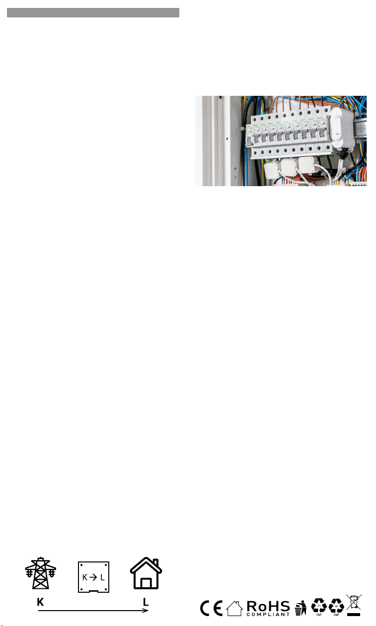
IT
GUIDA PER L’UTENTE E LA SICUREZZA
Contatore di energia Wi-Fi trifase
Leggi prima dell’uso
Questo documento contiene importanti informazioni tecniche e di sicu-
rezzasul dispositivo e sul suo uso e installazione in sicurezza.
⚠ATTENZIONE! Prima di iniziare l’installazione leggere attentamente e
completamente la documentazione allegata. La mancata osservanza delle
procedure consigliate potrebbe portare a malfunzionamenti, pericolo per la
vita o violazione della legge. Allterco Robotics EOOD non è responsabile per
eventuali perdite o danni in caso di installazione o funzionamento errati di
questo dispositivo.
Introduzione al prodotto
Shelly® è una linea di dispositivi innovativi gestiti da microprocessori che
permettono il controllo remoto degli elettrodomestici attraverso un telefo-
no cellulare, un tablet, un PC o un sistema domotico. I dispositivi Shelly®
sono in grado di funzionare autonomamente in una rete Wi-Fi locale o
possono anche essere gestiti attraverso servizi di automazione domesti-
ca cloud. Shelly Cloud è un servizio di questo tipo a cui si può accedere
utilizzando un’applicazione mobile Android o iOS o con qualsiasi browser
internet su https://home.shelly.cloud/. I dispositivi Shelly® sono accessibi-
li, controllati e monitorati a distanza da qualsiasi luogo in cui l’utente abbia
una connettività Internet, purché i dispositivi siano collegati a un router Wi-
Fi e a Internet. I dispositivi Shelly® hanno un’interfaccia web incorporata
accessibile a http://192.168.33.1 nella rete Wi-Fi, creata dal dispositivo in
modalità Access Point, o all’indirizzo URL del dispositivo nella rete Wi-Fi
a cui è connesso. L’interfaccia web incorporata può essere utilizzata per
monitorare e controllare il dispositivo, così come per regolare le sue im-
postazioni.
I dispositivi Shelly® sono in grado di comunicare direttamente con altri
dispositivi Wi-Fi attraverso il protocollo HTTP. Un’API è fornita da Allterco
Robotics EOOD. Per maggiori informazioni, visitare:
https://shelly-api-docs.shelly.cloud/#shelly-family-overview.
I dispositivi Shelly® vengono consegnati con un rmware installato in fabbri-
ca. Se sono necessari aggiornamenti del rmware per mantenere i disposi-
tivi in conformità, compresi gli aggiornamenti di sicurezza, Allterco Robotics
EOOD fornirà gli aggiornamenti gratuitamente attraverso l’interfaccia web in-
corporata del dispositivo o l’applicazione mobile Shelly, dove sono disponibili
le informazioni sulla versione corrente del rmware. La scelta di installare o
meno gli aggiornamenti del rmware del dispositivo è di esclusiva respon-
sabilità dell’utente. Allterco Robotics EOOD non è responsabile per qualsiasi
mancanza di conformità del dispositivo causata dalla mancata installazione
degli aggiornamenti forniti dall’utente in modo tempestivo.
Controlla la tua casa con la tua voce
Tutti i dispositivi Shelly sono compatibili con Amazon Echo e Google
Home. Consulta la nostra guida passo passo su:
https://shelly.cloud/support/compatibility/
Istruzioni per l’installazione
Il misuratore di energia Wi-Fi tripla fase, Shelly 3EM di Allterco Robotics
è destinato ad essere montato accanto agli interruttori, al ne di monito-
rare la potenza elettrica attraverso di esso, indipendente per ogni canale
e controllo di contattori pesanti. Shelly può funzionare come dispositivo
autonomo o come accessorio per un controller di automazione domestica.
Shelly 3EM può misurare l’energia in entrata e in uscita.
• Scopo del controllo: operativo
• Costruzione del controllo: montato in modo indipendente
• Azione di tipo 1.B
• Grado di inquinamento 2
• Tensione di impulso: 4000 V
A seconda di quante fasi vuoi misurare devi collegare il tuo Shelly 3EM
secondo lo schema fornito.
⚠ATTENZIONE! Pericolo di folgorazione. Il montaggio/installazione del
dispositivo alla rete elettrica deve essere eseguito con cautela da un elet-
tricista qualicato.
⚠ATTENZIONE! Pericolo di folgorazione. Ogni modica dei collegamenti
deve essere effettuata dopo essersi assicurati che non ci sia tensione ai
morsetti dell’apparecchio.
⚠ATTENZIONE! Utilizzare l’apparecchio solo con una rete elettrica e con
apparecchi conformi a tutte le norme vigenti. Un cortocircuito nella rete elet-
trica o in qualsiasi apparecchio collegato all’apparecchio può danneggiare
l’apparecchio.
⚠ATTENZIONE! Non collegare l’apparecchio ad apparecchi che superano
il carico massimo indicato!
⚠ATTENZIONE! Collegare l’apparecchio solo nel modo indicato in queste
istruzioni. Qualsiasi altro metodo potrebbe causare danni e/o lesioni.
⚠ATTENZIONE! Non installare il dispositivo in un luogo che possa ba-
gnarsi.
• Il primo passo consiste nell’installare i morsetti di misurazione sui li.
Aprire il trasformatore di corrente con un cacciavite quindi ssarlo sul
cavo di alimentazione desiderato. Eseguire questa operazione per tutti
i trasformatori di corrente, seguire il diagramma del usso di corrente.
ES
GUÍA DE USO Y SEGURIDAD
Medidor de energía Wi-Fi trifásico
Leer antes de usar
Este documento contiene información técnica y de seguridad importante so-
bre el aparato, su uso y su instalación segura.
⚠¡ATENCIÓN! Antes de comenzar la instalación, lea atentamente y por com-
pleto la documentación adjunta. El incumplimiento de los procedimientos reco-
mendados puede provocar un mal funcionamiento, un peligro para su vida o una
violación de la ley. Allterco Robotics no se hace responsable de cualquier pérdida
o daño debido a una instalación o uso inadecuado de este dispositivo.
Resumen del producto
Shelly® es una gama de innovadores dispositivos basados en microprocesa-
dores que permiten controlar a distancia los electrodomésticos a través de un
teléfono móvil, una tableta, un PC o un sistema domótico. Los dispositivos
Shelly® pueden funcionar de forma autónoma en una red Wi-Fi local o también
pueden ser operados por servicios de automatización del hogar a través del
Cloud. Shelly Cloud es un servicio que se puede utilizar a través de la aplicación
móvil Android o iOS, o a través de cualquier navegador web en https://home.
shelly.cloud/. Los dispositivos Shelly® se pueden manejar, controlar y super-
visar a distancia desde cualquier lugar en el que el usuario disponga de una
conexión a Internet, siempre que los dispositivos estén conectados a un router
Wi-Fi y a Internet. Los dispositivos Shelly® tienen una interfaz web integrada a
la que se puede acceder en http://192.168.33.1 dentro de la red Wi-Fi, creada
por el dispositivo en modo de punto de acceso, o en la URL del dispositivo en
la red Wi-Fi a la que está conectado. La interfaz web integrada puede utilizarse
para supervisar y controlar el dispositivo y ajustar su conguración.
Los dispositivos Shelly® pueden comunicarse directamente con otros dispo-
sitivos Wi-Fi a través de HTTP. Allterco Robotics EOOD proporciona una API.
Para más información, visite
https://shelly-api-docs.shelly.cloud/#shelly-family-overview.
Los dispositivos Shelly® vienen con el rmware instalado de fábrica. Si es ne-
cesario actualizar el rmware para que los dispositivos sigan cumpliendo la
normativa, incluidas las actualizaciones de seguridad, Allterco Robotics EOOD
proporcionará las actualizaciones de forma gratuita a través de la interfaz web
integrada en el dispositivo o la aplicación móvil Shelly, donde está disponible
la información de la versión actual del rmware. La decisión de instalar o no
las actualizaciones del rmware del dispositivo es responsabilidad exclusiva
del usuario. Allterco Robotics EOOD no se hace responsable de la falta de con-
formidad del Dispositivo causada por el hecho de que el Usuario no instale
oportunamente las actualizaciones previstas.
Controla tu casa con tu voz
Todos los dispositivos Shelly son compatibles con Amazon Echo y Google
Home. Consulte nuestra guía paso a paso en:
https://shelly.cloud/support/compatibility/.
Instrucciones de instalación
El contador de energía Wi-Fi trifásico Shelly 3EM de Allterco Robotics está di-
señado para ser montado junto a los disyuntores para supervisar la energía
eléctrica que uye a través de ellos, de forma independiente para cada canal
y con control de contactores de alta resistencia. Shelly puede funcionar como
dispositivo autónomo o como accesorio de un controlador domótico. Shelly
3EM puede medir la energía entrante y saliente.
• Finalidad del control: Funcionamiento
• Construcción del control: Montaje independiente
• Acción de tipo 1.B
• Grado de contaminación 2
• Tensión de impulso: 4000 V
En función del número de fases que desee medir, deberá conectar su Shelly
3EM según el esquema suministrado.
⚠¡ATENCIÓN! Peligro de descarga eléctrica. El montaje/instalación del aparato
a la red eléctrica debe ser realizado con cuidado, por un electricista cualicado.
⚠¡ATENCIÓN! Peligro de descarga eléctrica. Cualquier modicación de las
conexiones debe realizarse después de asegurarse de que no hay tensión en
los terminales del Dispositivo.
⚠¡ATENCIÓN! Utilice el dispositivo sólo con una fuente de alimentación y un
equipo que cumplan con todas las normas aplicables. Un cortocircuito en la red
eléctrica o en cualquier dispositivo conectado al aparato puede dañar el aparato.
⚠¡ATENCIÓN! No conecte el aparato a dispositivos que superen la carga máxi-
ma indicada.
⚠¡ATENCIÓN! Conecte el aparato sólo de la manera indicada en estas instruc-
ciones. Cualquier otro método puede causar daños y/o lesiones.
⚠¡ATENCIÓN! No instale el aparato en un lugar donde pueda mojarse.
• El primer paso es instalar las pinzas de medición en los cables. Abra el
transformador de corriente con un destornillador y conéctelo al cable de ali-
mentación deseado. Haga esto para todos los transformadores de corriente,
siguiendo el diagrama en
En la parte inferior de su transformador de núcleo dividido,
verá una flecha que muestra la dirección del flujo de energía.
corriente de núcleo dividido
transformador
• El segundo paso es cablear la fase al terminal respetado del Shelly 3EM. Utili-
PT
GUIA DO UTILIZADOR E DE SEGURANÇA
Medidor Wi-Fi de Energia Trifásico
Leia antes de utilizar
Este documento contém importante informação técnica e de segurança rela-
tiva ao dispositivo, sua utilização segura e instalação.
⚠ATENÇÃO! Antes de iniciar a instalação, por favor leia atentamente e na ínte-
gra a documentação incluída. O incumprimento dos procedimentos recomenda-
dos poderão dar origem a avarias, perigo à sua vida ou violação da lei. A Allterco
Robotics EOOD não se responsabiliza por quaisquer perdas ou danos em caso
de uma incorreta instalação ou incorreta utilização deste dispositivo.
Apresentação do Produto
Shelly® é uma linha de dispositivos inovadores geridos por micro-processador,
que permitem o controlo remote de eletrodomésticos através de telemóvel,
tablet, PC ou sistema de domótica. Os dispositivos Shelly® podem funcionar
isoladamente numa rede Wi-Fi local ou podem também ser operados através
de serviços de domótica em nuvem. Shelly Cloud é um desses serviços que
pode ser acedido usando uma aplicação móvel Android ou iOS, ou com um
qualquer browser de internet em https://home.shelly.cloud/. Os dispositivos
Shelly® podem ser acedidos, controlados e monitorizados remotamente a
partir de qualquer localização onde o Utilizador tiver uma conexão à internet,
desde que os dispositivos estejam conectados a um router Wi-Fi e à Internet.
Os dispositivos Shelly® possuem um Interface Web embutido e acessível em
http://192.168.33.1 na rede Wi-Fi, criada pelo dispositivo em modo Ponto de
Acesso (AP), ou no endereço URL do dispositivo na rede Wi-Fi a que está liga-
do. O Interface Web embutido pode ser usado para monitorizar e controlar o
dispositivo, assim como ajustar as suas congurações.
Os dispositivos Shelly® podem comunicar diretamente com outros dispositi-
vos Wi-Fi através do protocolo HTTP. Uma App é fornecida por Allterco Roboti-
cs EOOD. Para mais informação, por favor visite:
https://shelly-api-docs.shelly.cloud/#shelly-family-overview.
Os dispositivos Shelly® são distribuidos com rmware instalado em fábrica.
Se forem necessárias atualizações ao rmware de forma a manter os dispo-
sitivos em conformidade, incluindo atualizações de segurança, Allterco Robo-
tics EOOD fornecerá as atualizações gratuitamente através do Interface Web
embutido ou da Aplicação Móvel Shelly, onde a informação sobre a versão de
rmware atual se encontra acessível. A escolha em instalar ou não instalar as
atualizações de rmware do Dispositivo é responsabilidade única do utilizador.
Allterco Robotics EOOD não se responsabiliza por qualquer falha na conformi-
dade do Dispositivo causada pela não instalação das atualizações disponíveis
em tempo útil, por parte do Utilizador.
Controle a sua casa com a sua voz
Todos os dispositivos Shelly são compatíveis com Amazon Echo e Google
Home. Por favor consulte o nosso manual passo-a-passo em: https://shelly.
cloud/support/compatibility/
Instruções de Instalação
O Medidor Wi-Fi de Energia Trifásico Shelly 3EM da Allterco Robotics foi de-
senhado para ser montado junto dos disjuntores, de forma a monitorizar a
corrente eléctrica através dos mesmos, para cada canal e cada contactor de
controlo de potência. Shelly pode funcionar como um Dispositivo isolado ou
como acessório de um controlador de domótica. Shelly 3EM consegue medir
energia no sentido de entrada e de saída.
• Finalidade do controlo: Operativo
• Construção do controlo: Montado independentemente
• Ação Tipo 1.B
• Grau de Poluição 2
• Voltagem de impulso: 4000 V
Dependendo do número de fases que quer medir, terá de conetar o seu Shelly
3EM de acordo com o esquema fornecido.
⚠ATENÇÃO! Perigo de eletrocussão. A montagem/instalação do Dispositivo à
rede elétrica deve ser executada com precaução, por um eletricista qualicado.
⚠ATENÇÃO! Perigo de eletrocussão. Qualquer alteração nas ligações só deve
ser executada depois de assegurado de que não existe qualquer voltagem nos
terminais do Dispositivo.
⚠ATENÇÃO! Utilize o Dispositivo apenas com uma rede elétrica e eletrodo-
mésticos que estejam de acordo com os regulamentos aplicáveis. Um curto-cir-
cuito na rede elétrica ou num dos eletrodomésticos conectados poderá danicar
o Dispositivo.
⚠ATENÇÃO! Não conecte o Dispositivo a electrodomésticos se estes excede-
rem a carga máxima permitida.
⚠ATENÇÃO! Conecte o Dispositivo apenas da forma ilustrada nestas instru-
ções. Qualquer outra forma poderá causar danos e/ou acidentes.
⚠ATENÇÃO! Não instale o dispositivo num local que possa car molhado.
• O primeiro passo é ligar os terminais de medição aos cabos condutores. Abra
o transformador de corrente com uma chave de parafusos e acople-o sobre
o cabo de tensão. Proceda da mesma forma com todos os transformadores.
Por favor siga o diagrama do sentido da corrente.
Na parte inferior do seu transformador de núcleo dividido,
você verá uma seta mostrando a direção do fluxo de energia.
corrente Split-Core
transformador
FR
GUIDE D’UTILISATION ET DE SÉCURITÉ
Compteur d’énergie Wi-Fi triphasé
A lire avant utilisation
Ce document contient des informations techniques et de sécurité impor-
tantes concernant l’appareil, son utilisation et son installation en toute sé-
curité.
⚠ATTENTION! Avant de commencer l’installation, veuillez lire attentivement
et complètement la documentation d’accompagnement. Le non-respect des
procédures recommandées peut entraîner un dysfonctionnement, un danger
pour votre vie ou une violation de la loi. Allterco Robotics EOOD n’est pas res-
ponsable des pertes ou des dommages en cas d’installation ou d’utilisation
incorrecte de ce dispositif.
Présentation du produit
Shelly® est une gamme de dispositifs innovants gérés par microprocesseur,
qui permettent de contrôler à distance les appareils électriques par le biais
d’un téléphone mobile, d’une tablette, d’un PC ou d’un système domotique.
Les dispositifs Shelly® peuvent fonctionner de manière autonome sur un
réseau local Wi-Fi ou ils peuvent également être exploités par des services
domotiques via Cloud. Shelly Cloud est un service utilisable via l’application
mobile Android ou iOS, ou via n’importe quel navigateur Internet sur https://
home.shelly.cloud/. Les dispositifs Shelly® peuvent être utilisés, contrôlés
et surveillés à distance depuis n’importe quel endroit où l’utilisateur dispose
d’une connexion Internet, à condition que les dispositifs soient connectés à
un routeur Wi-Fi et à Internet. Les dispositifs Shelly® ont une interface Web
intégrée accessible sur http://192.168.33.1 au sein du réseau Wi-Fi, créé par
le dispositif en mode point d’accès, ou à l’adresse URL du dispositif sur le ré-
seau Wi-Fi auquel il est connecté. L’interface Web intégrée peut être utilisée
pour surveiller et contrôler le dispositif, ainsi que pour ajuster ses paramètres.
Les dispositifs Shelly® peuvent communiquer directement avec d’autres dis-
positifs Wi-Fi par le biais du protocole HTTP. Une API est fournie par Allterco
Robotics EOOD. Pour plus d’informations, veuillez visiter :
https://shelly-api-docs.shelly.cloud/#shelly-family-overview.
Les dispositifs Shelly® sont livrés avec un micrologiciel installé en usine. Si
des mises à jour du micrologiciel sont nécessaires pour maintenir les dispo-
sitifs en conformité, y compris des mises à jour de sécurité, Allterco Robotics
EOOD fournira les mises à jour gratuitement via l’interface Web intégrée au dis-
positif ou l’application mobile Shelly, où les informations sur la version actuelle
du micrologiciel sont disponibles. Le choix d’installer ou non les mises à jour
du micrologiciel du dispositif relève de la seule responsabilité de l’Utilisateur.
Allterco Robotics EOOD ne sera pas responsable de tout manque de confor-
mité du Dispositif causé par le fait que l’Utilisateur n’a pas installé les mises à
jour fournies en temps voulu.
Contrôlez votre maison avec votre voix
Tous les dispositifs Shelly sont compatibles avec Amazon Echo et Google
Home. Veuillez consulter notre guide étape par étape sur :
https://shelly.cloud/support/compatibility/.
Instructions d’installation
Le compteur d’énergie Wi-Fi triphasé Shelly 3EM d’Allterco Robotics est desti-
né à être monté à côté des disjoncteurs, an de surveiller l’énergie électrique
qui y passe, indépendamment pour chaque canal et avec un contrôle des
contacteurs à usage intensif. Shelly peut fonctionner comme un dispositif
autonome ou comme accessoire d’un contrôleur domotique. Shelly 3EM peut
mesurer l’énergie entrante et sortante.
• Objectif de la commande : Fonctionnement
• Construction de la commande : Montée de façon indépendante
• Type 1.B Action
• Degré de pollution 2
• Tension d’impulsion : 4000 V
En fonction du nombre de phases que vous souhaitez mesurer, vous devez
connecter votre Shelly 3EM selon le schéma fourni.
⚠ATTENTION! Danger d’électrocution. Le montage/installation de l’Appareil
sur le réseau électrique doit être effectué avec prudence, par un électricien
qualié.
⚠ATTENTION! Danger d’électrocution. Chaque modication des connexions
doit être effectuée après s’être assuré de l’absence de tension aux bornes du
Dispositif.
⚠ATTENTION! N’utilisez l’Appareil qu’avec un réseau électrique et des appa-
reils conformes à toutes les réglementations applicables. Un court-circuit sur
le réseau électrique ou tout appareil connecté à l’Appareil peut endommager
l’Appareil.
⚠ATTENTION! Ne connectez pas l’Appareil à des appareils dépassant la
charge maximale indiquée !
⚠ATTENTION! Connectez l’Appareil uniquement de la manière indiquée dans
ces instructions. Toute autre méthode pourrait causer des dommages et/ou
des blessures.
⚠ATTENTION! N’installez pas l’appareil à un endroit où il est possible qu’il
se mouille.
• La première étape consiste à installer les pinces de mesure sur les ls.
Ouvrez le transformateur de courant avec un tournevis puis xez-le sur le
câble d’alimentation souhaité. Faites ceci pour tous les transformateurs de
courant, suivez le schéma de
Nella parte inferiore del trasformatore a nucleo diviso, vedrai
una freccia che mostra la direzione del flusso di energia.
corrente split core
trasformatore
• Il secondo passo consiste nel collegare la fase al terminale rispettato
su Shelly 3EM. Si prega di utilizzare il lo e serrarlo bene con la vite sui
terminali Shelly.
• L’ultimo passaggio consiste nel collegare l’alimentazione al dispositivo. Si
prega di collegare il cavo di alimentazione al terminale rispettato.
Devi seguire uno dei diagrammi proposti:
Schema di cablaggio trifase – Fig.1
Cablaggio bifase (US) – Fig.2
Cablaggio di misurazione dell’energia solare monofase + separato – Fig.3
Cablaggio monofase no a 3 circuiti diversi – Fig.4
⚠ATTENZIONE! Collegare i trasformatori di corrente di conseguenza per
ogni canale! Ogni trasformatore di corrente è marcato e calibrato per il ri-
spettivo ingresso del Dispositivo. Qualsiasi collegamento improprio porterà
a misurazioni e visualizzazioni errate del dispositivo.
Inclusione iniziale
Se si sceglie di utilizzare il dispositivo con l’applicazione mobile Shelly
Cloud e il servizio Shelly Cloud, le istruzioni su come collegare il dispositivo
al Cloud e controllarlo attraverso l’App Shelly si trovano nella “Guida App”
www.shelly.cloud/app-guide
. L’applicazione mobile Shelly e il servizio
Shelly Cloud non sono condizioni per il corretto funzionamento del Disposi-
tivo. Questo Dispositivo può essere utilizzato con vari altri servizi e applica-
zioni di automazione domestica.
⚠ATTENZIONE! Non permettere ai bambini di giocare con i pulsanti/inter-
ruttori collegati al Dispositivo. Tenere i dispositivi per il controllo remoto di
Shelly (telefoni cellulari, tablet, PC) lontano dai bambini.
Speciche
• Alimentazione: 110-240 VAC, 50/60Hz
• Misurazione massima per canale: 120 A
• Carico massimo relè: 10 A / 240 VAC
• Temperatura di esercizio: da -20°C a 40°C
• Potenza massima in uscita RF: 10.82 dBm
• Protocollo radio: Wi-Fi 802.11 b/g/n
• Frequenza: 2412-2472 Hz; (Massimo 2483,5 MHz)
• Gamma operativa (a seconda della costruzione locale):
- no a 50 m all’aperto
- no a 30 m in interni
• Dimensioni (AxPxL): 73x57x22 mm
• Consumo elettrico: < 1W
• MQTT: SÌ
• CoAP: SÌ
• Webhooks (azioni URL): 8 con 5 URL per hook
• Pianicazioni: 20
Rilevamento furto di energia
Per rendere disponibile questa funzione, potrebbe essere necessario ag-
giornare il rmware del dispositivo. Con un trasformatore di corrente a nu-
cleo diviso aggiuntivo, collegato al terminale IN-IN+ di Shelly 3EM, potresti
ricevere una notica in caso di furto o dispersione di energia. Si prega di
seguire gli schemi elettrici di g. 1 e 2, a seconda dell’applicazione.
Dichiarazione di conformità
Con la presente, Allterco Robotics EOOD dichiara che il tipo di apparecchiatura
radio Shelly 3EM è conforme alla Direttiva 2014/53/UE, 2014/35/UE, 2014/30/
UE, 2011/65/UE. Il testo completo della dichiarazione di conformità UE è di-
sponibile al seguente indirizzo Internet: https://shelly.link/3em_DoC
Produttore: Allterco Robotics EOOD
Indirizzo: Bulgaria, Soa, 1407, 103 Cherni vrah Blvd.
Tel.: +359 2 988 7435
E-mail: support@shelly.cloud Web: http://www.shelly.cloud
Le modiche ai dati di contatto sono pubblicate dal Produttore all’indirizzo
il sito uciale del Dispositivo http://www.shelly.cloud
Tutti i diritti sul marchio Shelly® e altri diritti intellettuali associati a questo
dispositivo appartengono a Allterco Robotics EOOD.
za cable y apriétalo bien con los tornillos de los terminales Shelly.
• El último paso es conectar la fuente de alimentación al dispositivo. Conecte El
cable de alimentación al terminal correspondiente.
Diagrama de cableado trifásico - Fig. 1
Cableado bifásico (EE.UU.) - Fig.2
Cableado monofásico + medición separada de la energía solar - Fig.3
Cableado monofásico de hasta 3 circuitos diferentes - Fig.4
⚠¡CUIDADO! ¡Conecte los transformadores de corriente de forma adecuada
para cada canal! Cada transformador de corriente está marcado y calibrado para
la entrada respectiva del aparato. Cualquier conexión incorrecta dará lugar a una
medición y visualización incorrectas del Dispositivo.
Inclusión inicial
Si decide utilizar el Dispositivo con la aplicación móvil Shelly Cloud y el ser-
vicio Shelly Cloud, las instrucciones para conectar el Dispositivo al Cloud
y controlarlo a través de la App Shelly se encuentran en la “Guía de la App”
www.shelly.cloud/app-guide
. La aplicación móvil Shelly y el servicio Shelly
Cloud no son condiciones para el buen funcionamiento del Dispositivo. Este
dispositivo puede utilizarse con otros servicios y aplicaciones de domótica.
⚠¡ATENCIÓN! No permita que los niños jueguen con los botones/interrupto-
res conectados al aparato. Mantenga los dispositivos que permiten el control
remoto de Shelly (teléfonos móviles, tabletas, ordenadores) fuera del alcance
de los niños.
Características:
• Alimentación: 110-240 VAC, 50/60Hz
• Máxima medición por canal: 120 A
• Carga máxima del relé: 10 A / 240 VCA
• Temperatura de funcionamiento : -20°C a 40°C
• Potencia máxima de salida de RF: 10.82 dBm
• Protocolo de radio: Wi-Fi 802.11 b/g/n
• Frecuencia: 2412-2472 МHz; (máx. 2483,5 MHz)
• Distancia operativa (dependiendo de la construcción local):
- hasta 50 m en el exterior
- hasta 30 m en interior
• Dimensiones (HxAxA): 73x57x22 mm
• Consumo de energía: < 1W
• MQTT: SÍ
• CoAP: SÍ
• Webhooks (acciones URL): 8 con 5 URLs por hook
• Agendamentos: 20
Detección de robos de energía
Para que esta función esté disponible, es posible que tengas que actualizar el
rmware de tu dispositivo. Con un transformador de corriente de núcleo divi-
dido adicional conectado al terminal IN- IN+ del Shelly 3EM, puede recibir una
noticación, si hay un robo de energía o una fuga. Por favor, siga los diagramas
de cableado de las imágenes 1 y 2, dependiendo de su aplicación.
Declaración de conformidad
Allterco Robotics EOOD declara que el equipo de radio Shelly 3EM cumple con
las directivas 2014/53/UE, 2014/35/UE, 2014/30/UE, 2011/65/ UE. El texto
completo de la declaración de conformidad de la UE está disponible en la si-
guiente dirección web:
https://shelly.link/3em_DoC
Fabricante: Allterco Robotics EOOD
Dirección: Bulgaria, Soa, 1407, 103 Cherni vrah Blvd.
Tel.: +359 2 988 7435
Correo electrónico: support@shelly.cloud
Web: http://www.shelly.cloud
Los cambios en los datos de contacto son publicados por el fabricante en el
sitio web ocial del dispositivo http://www.shelly.cloud
Todos los derechos de la marca Shelly® y otros derechos de propiedad intelec-
tual asociados a este dispositivo pertenecen a Allterco Robotics EOOD.
• O segundo passo é conectar a fase ao respetivo terminal no Shelly 3EM. Por
favor utilize o e aperte bem os parafusos nos terminais do Shelly.
• O último passo é conectar a alimentação ao dispositivo. Por favor conecte o
cabo de alimentação ao respetivo terminal.
Esquema de ligação trifásica - Fig.1
Esquema de ligação difásica (US) - Fig.1
Esquema de ligação monofásica + Medição independente de painel de energia
solar - Fig.3
Esquema de ligação monofásica para até 3 circuitos independentes - Fig.4
⚠ATENÇÃO! Conecte os transformadores de corrente de acordo com cada
canal. Cada transformador de corrente está identicado e calibrado para a res-
pectiva entrada do Dispositivo. Qualquer conecção indevida dará origem a uma
incorrecta medição e visualização.
Inclusão Inicial
Se escolher usar o Dispositivo com a aplicação móvel Shelly Cloud e o servi-
ço Shelly Cloud, instruções em como conectar o Dispositivo à Cloud e como
controlá-lo através da App Shelly, podem ser encontradas no “Guia da App”
www.shelly.cloud/app-guide
. A Shelly Mobile Application e o serviço Shelly
Cloud não são condições únicas para o funcionamento adequado do disposi-
tivo. Este Dispositivo pode ser utilizado com variadas aplicações e serviços
de domótica.
⚠¡ATENCIÓN! No permita que los niños jueguen con los botones/interrupto-
res conectados al aparato. Mantenga los dispositivos que permiten el control
remoto de Shelly (teléfonos móviles, tabletas, ordenadores) fuera del alcance
de los niños.
Especicações
• Fonte de alimentação: 110-240 VAC, 50/60Hz
• Medição máxima por canal: 120 A
• Carga máxima da relé: 10 A / 240 VCA
• Temperatura de funcionamento: -20°C até 40°C
• Potência máx. de saída RF: 10.82 dBm
• Protocolo de rádio: Wi-Fi 802.11 b/g/n
• Frequência: 2412-2472 МHz; (Máx. 2483.5 MHz)
• Alcance de funcionamento (dependendo da construção local):
- até 50 m ao ar livre
- até 30 m no interior
• Dimensões (AxLxP): 73x57x22 mm
• Consumo elétrico: < 1W
• MQTT: Sim
• CoAP: Sim
• Webhooks (acções de URL): 8 com 5 URLs por hook
• Horarios: 20
Deteção de Furto de Energia
Para ter esta funcionalidade disponível, poderá ter de actualizar o rmware do
seu dispositivo. Com um transformador de corrente Split-Core adicional, co-
nectado aos terminais IN- IN+ do Shelly 3EM, poderá receber uma noticação
se existir furto ou perda de energia. Por favor siga os diagramas de ligação na
g. 1 e 2, dependendo da sua aplicação.
Declaração de conformidade
Alterco Robotics EOOD declara, por este meio, que o tipo de equipamento
Shelly 3EM está em conformidade com as Directivas 2014/53/ EU, 2014/35/
EU, 2014/30/EU, 2011/65/EU. O texto completo da declaração de conformida-
de da UE está disponível no seguinte endereço de internet:
https://shelly.link/3em_DoC
Fabricante: Allterco Robotics EOOD
Endereço: Soa, 1407, 103 Cherni vrah Blvd. Bulgária
Tel.: +359 2 988 7435
E-mail: support@shelly.cloud
Web: https://www.shelly.cloud
Quaisquer alterações aos dados de contato serão publicados pelo Fabricante
no website ocial do Dispositivo https://www.shelly.cloud
Todos os direito da marca Shelly®, e quaisquer outros diretios intelectuais as-
sociados a este Dispositivo pertencem à Allterco Robotics EOOD.
Au bas de votre transformateur à noyau divisé, vous verrez
une flèche indiquant la direction du flux d'énergie.
courant de noyau divisé
transformateur
• La deuxième étape consiste à câbler la phase à la borne respectée du Shelly
3EM. Utilisez du l et serrez-le bien avec les vis sur les bornes Shelly.
• La dernière étape consiste à connecter l’alimentation à l’appareil. Connectez
le l d’alimentation à la borne correspondante.
Vous devez suivre l’un des schémas proposés :
Schéma de câblage triphasé - Img.1
Câblage 2 phases (US) - Img.2
Câblage 1 phase + mesure séparée de l’énergie solaire - Img.3
Câblage monophasé jusqu’à 3 circuits différents - Img.4
⚠ATTENTION! Connectez les transformateurs de courant en conséquence
pour chaque canal ! Chaque transformateur de courant est marqué et calibré
pour l’entrée respective de l’Appareil. Toute connexion incorrecte entraînera une
mesure et une visualisation incorrectes de l’appareil.
Inclusion initiale
Si vous choisissez d’utiliser l’Appareil avec l’application mobile Shelly Cloud
et le service Shelly Cloud, les instructions pour connecter l’Appareil au
Cloud et le contrôler via l’App Shelly se trouvent dans le “ Guide de l’App “
www.shelly.cloud/app-guide
. L’application mobile Shelly et le service Shelly
Cloud ne sont pas des conditions au bon fonctionnement de l’Appareil. Cet Ap-
pareil peut être utilisé avec divers autres services et applications domotiques.
⚠ATTENTION! Ne laissez pas les enfants jouer avec les boutons/interrupteurs
connectés à l’Appareil. Gardez les Dispositifs permettant de contrôler Shelly à
distance (téléphones mobiles, tablettes, PC) hors de portée des enfants.
Caractéristiques:
• Alimentation électrique : 110-240 VAC, 50/60Hz
• Mesure maximale par canal : 120 A
• Charge maximale du relais : 10 A / 240 VCA
• Température de fonctionnement : -20°C à 40°C
• Puissance de sortie RF maximale: 10.82 dBm
• Protocole radio : Wi-Fi 802.11 b/g/n
• Fréquence : 2412-2472 МHz ; (Max. 2483.5 MHz)
• Distance opérationnelle (en fonction de la construction locale) :
-jusqu’à 50 m en extérieur
-jusqu’à 30 m à l’intérieur
• Dimensions (HxLxL) : 73x57x22 mm
• Consommation électrique : < 1W
• MQTT : Oui
• CoAP : Oui
• Webhooks (actions URL) : 8 avec 5 URL par crochet
• Planications : 20
Détection de vol d’énergie
Pour que cette fonction soit disponible, vous devrez peut-être mettre à jour le
micrologiciel de votre appareil. Avec un transformateur de courant supplémen-
taire à noyau divisé, connecté à la borne IN- IN+ du Shelly 3EM, vous pouvez
recevoir une notication, s’il y a un vol ou une fuite d’énergie. Veuillez suivre
les schémas de câblage des images 1 et 2, en fonction de votre application.
Déclaration de conformité
Par la présente, Allterco Robotics EOOD déclare que l’équipement radio
de type Shelly 3EM est conforme à la directive 2014/53/EU, 2014/35/ EU,
2014/30/EU, 2011/65/EU. Le texte complet de la déclaration de conformité
UE est disponible à l’adresse internet suivante :
https://shelly.link/3em_DoC
Fabricant: Allterco Robotics EOOD
Adresse: Bulgarie, Soa, 1407, 103 Cherni vrah Blvd.
Tél: +359 2 988 7435
Courriel: support@shelly.cloud Web: http://www.shelly.cloud
Les modications des données de contact sont publiées par le fabricant sur le
site ociel du dispositif http://www.shelly.cloud
Tous les droits sur la marque Shelly® et les autres droits intellectuels associés
à ce dispositif appartiennent à Allterco Robotics EOOD.
50/2022
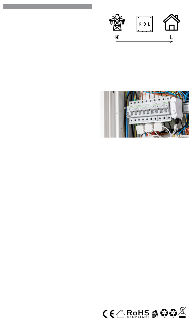
IT
GUIDA PER L’UTENTE E LA SICUREZZA
Contatore di energia Wi-Fi trifase
Leggi prima dell’uso
Questo documento contiene importanti informazioni tecniche e di sicu-
rezzasul dispositivo e sul suo uso e installazione in sicurezza.
⚠ATTENZIONE! Prima di iniziare l’installazione leggere attentamente e
completamente la documentazione allegata. La mancata osservanza delle
procedure consigliate potrebbe portare a malfunzionamenti, pericolo per la
vita o violazione della legge. Allterco Robotics EOOD non è responsabile per
eventuali perdite o danni in caso di installazione o funzionamento errati di
questo dispositivo.
Introduzione al prodotto
Shelly® è una linea di dispositivi innovativi gestiti da microprocessori che
permettono il controllo remoto degli elettrodomestici attraverso un telefo-
no cellulare, un tablet, un PC o un sistema domotico. I dispositivi Shelly®
sono in grado di funzionare autonomamente in una rete Wi-Fi locale o
possono anche essere gestiti attraverso servizi di automazione domesti-
ca cloud. Shelly Cloud è un servizio di questo tipo a cui si può accedere
utilizzando un’applicazione mobile Android o iOS o con qualsiasi browser
internet su https://home.shelly.cloud/. I dispositivi Shelly® sono accessibi-
li, controllati e monitorati a distanza da qualsiasi luogo in cui l’utente abbia
una connettività Internet, purché i dispositivi siano collegati a un router Wi-
Fi e a Internet. I dispositivi Shelly® hanno un’interfaccia web incorporata
accessibile a http://192.168.33.1 nella rete Wi-Fi, creata dal dispositivo in
modalità Access Point, o all’indirizzo URL del dispositivo nella rete Wi-Fi
a cui è connesso. L’interfaccia web incorporata può essere utilizzata per
monitorare e controllare il dispositivo, così come per regolare le sue im-
postazioni.
I dispositivi Shelly® sono in grado di comunicare direttamente con altri
dispositivi Wi-Fi attraverso il protocollo HTTP. Un’API è fornita da Allterco
Robotics EOOD. Per maggiori informazioni, visitare:
https://shelly-api-docs.shelly.cloud/#shelly-family-overview.
I dispositivi Shelly® vengono consegnati con un rmware installato in fabbri-
ca. Se sono necessari aggiornamenti del rmware per mantenere i disposi-
tivi in conformità, compresi gli aggiornamenti di sicurezza, Allterco Robotics
EOOD fornirà gli aggiornamenti gratuitamente attraverso l’interfaccia web in-
corporata del dispositivo o l’applicazione mobile Shelly, dove sono disponibili
le informazioni sulla versione corrente del rmware. La scelta di installare o
meno gli aggiornamenti del rmware del dispositivo è di esclusiva respon-
sabilità dell’utente. Allterco Robotics EOOD non è responsabile per qualsiasi
mancanza di conformità del dispositivo causata dalla mancata installazione
degli aggiornamenti forniti dall’utente in modo tempestivo.
Controlla la tua casa con la tua voce
Tutti i dispositivi Shelly sono compatibili con Amazon Echo e Google
Home. Consulta la nostra guida passo passo su:
https://shelly.cloud/support/compatibility/
Istruzioni per l’installazione
Il misuratore di energia Wi-Fi tripla fase, Shelly 3EM di Allterco Robotics
è destinato ad essere montato accanto agli interruttori, al ne di monito-
rare la potenza elettrica attraverso di esso, indipendente per ogni canale
e controllo di contattori pesanti. Shelly può funzionare come dispositivo
autonomo o come accessorio per un controller di automazione domestica.
Shelly 3EM può misurare l’energia in entrata e in uscita.
• Scopo del controllo: operativo
• Costruzione del controllo: montato in modo indipendente
• Azione di tipo 1.B
• Grado di inquinamento 2
• Tensione di impulso: 4000 V
A seconda di quante fasi vuoi misurare devi collegare il tuo Shelly 3EM
secondo lo schema fornito.
⚠ATTENZIONE! Pericolo di folgorazione. Il montaggio/installazione del
dispositivo alla rete elettrica deve essere eseguito con cautela da un elet-
tricista qualicato.
⚠ATTENZIONE! Pericolo di folgorazione. Ogni modica dei collegamenti
deve essere effettuata dopo essersi assicurati che non ci sia tensione ai
morsetti dell’apparecchio.
⚠ATTENZIONE! Utilizzare l’apparecchio solo con una rete elettrica e con
apparecchi conformi a tutte le norme vigenti. Un cortocircuito nella rete elet-
trica o in qualsiasi apparecchio collegato all’apparecchio può danneggiare
l’apparecchio.
⚠ATTENZIONE! Non collegare l’apparecchio ad apparecchi che superano
il carico massimo indicato!
⚠ATTENZIONE! Collegare l’apparecchio solo nel modo indicato in queste
istruzioni. Qualsiasi altro metodo potrebbe causare danni e/o lesioni.
⚠ATTENZIONE! Non installare il dispositivo in un luogo che possa ba-
gnarsi.
• Il primo passo consiste nell’installare i morsetti di misurazione sui li.
Aprire il trasformatore di corrente con un cacciavite quindi ssarlo sul
cavo di alimentazione desiderato. Eseguire questa operazione per tutti
i trasformatori di corrente, seguire il diagramma del usso di corrente.
ES
GUÍA DE USO Y SEGURIDAD
Medidor de energía Wi-Fi trifásico
Leer antes de usar
Este documento contiene información técnica y de seguridad importante so-
bre el aparato, su uso y su instalación segura.
⚠¡ATENCIÓN! Antes de comenzar la instalación, lea atentamente y por com-
pleto la documentación adjunta. El incumplimiento de los procedimientos reco-
mendados puede provocar un mal funcionamiento, un peligro para su vida o una
violación de la ley. Allterco Robotics no se hace responsable de cualquier pérdida
o daño debido a una instalación o uso inadecuado de este dispositivo.
Resumen del producto
Shelly® es una gama de innovadores dispositivos basados en microprocesa-
dores que permiten controlar a distancia los electrodomésticos a través de un
teléfono móvil, una tableta, un PC o un sistema domótico. Los dispositivos
Shelly® pueden funcionar de forma autónoma en una red Wi-Fi local o también
pueden ser operados por servicios de automatización del hogar a través del
Cloud. Shelly Cloud es un servicio que se puede utilizar a través de la aplicación
móvil Android o iOS, o a través de cualquier navegador web en https://home.
shelly.cloud/. Los dispositivos Shelly® se pueden manejar, controlar y super-
visar a distancia desde cualquier lugar en el que el usuario disponga de una
conexión a Internet, siempre que los dispositivos estén conectados a un router
Wi-Fi y a Internet. Los dispositivos Shelly® tienen una interfaz web integrada a
la que se puede acceder en http://192.168.33.1 dentro de la red Wi-Fi, creada
por el dispositivo en modo de punto de acceso, o en la URL del dispositivo en
la red Wi-Fi a la que está conectado. La interfaz web integrada puede utilizarse
para supervisar y controlar el dispositivo y ajustar su conguración.
Los dispositivos Shelly® pueden comunicarse directamente con otros dispo-
sitivos Wi-Fi a través de HTTP. Allterco Robotics EOOD proporciona una API.
Para más información, visite
https://shelly-api-docs.shelly.cloud/#shelly-family-overview.
Los dispositivos Shelly® vienen con el rmware instalado de fábrica. Si es ne-
cesario actualizar el rmware para que los dispositivos sigan cumpliendo la
normativa, incluidas las actualizaciones de seguridad, Allterco Robotics EOOD
proporcionará las actualizaciones de forma gratuita a través de la interfaz web
integrada en el dispositivo o la aplicación móvil Shelly, donde está disponible
la información de la versión actual del rmware. La decisión de instalar o no
las actualizaciones del rmware del dispositivo es responsabilidad exclusiva
del usuario. Allterco Robotics EOOD no se hace responsable de la falta de con-
formidad del Dispositivo causada por el hecho de que el Usuario no instale
oportunamente las actualizaciones previstas.
Controla tu casa con tu voz
Todos los dispositivos Shelly son compatibles con Amazon Echo y Google
Home. Consulte nuestra guía paso a paso en:
https://shelly.cloud/support/compatibility/.
Instrucciones de instalación
El contador de energía Wi-Fi trifásico Shelly 3EM de Allterco Robotics está di-
señado para ser montado junto a los disyuntores para supervisar la energía
eléctrica que uye a través de ellos, de forma independiente para cada canal
y con control de contactores de alta resistencia. Shelly puede funcionar como
dispositivo autónomo o como accesorio de un controlador domótico. Shelly
3EM puede medir la energía entrante y saliente.
• Finalidad del control: Funcionamiento
• Construcción del control: Montaje independiente
• Acción de tipo 1.B
• Grado de contaminación 2
• Tensión de impulso: 4000 V
En función del número de fases que desee medir, deberá conectar su Shelly
3EM según el esquema suministrado.
⚠¡ATENCIÓN! Peligro de descarga eléctrica. El montaje/instalación del aparato
a la red eléctrica debe ser realizado con cuidado, por un electricista cualicado.
⚠¡ATENCIÓN! Peligro de descarga eléctrica. Cualquier modicación de las
conexiones debe realizarse después de asegurarse de que no hay tensión en
los terminales del Dispositivo.
⚠¡ATENCIÓN! Utilice el dispositivo sólo con una fuente de alimentación y un
equipo que cumplan con todas las normas aplicables. Un cortocircuito en la red
eléctrica o en cualquier dispositivo conectado al aparato puede dañar el aparato.
⚠¡ATENCIÓN! No conecte el aparato a dispositivos que superen la carga máxi-
ma indicada.
⚠¡ATENCIÓN! Conecte el aparato sólo de la manera indicada en estas instruc-
ciones. Cualquier otro método puede causar daños y/o lesiones.
⚠¡ATENCIÓN! No instale el aparato en un lugar donde pueda mojarse.
• El primer paso es instalar las pinzas de medición en los cables. Abra el
transformador de corriente con un destornillador y conéctelo al cable de ali-
mentación deseado. Haga esto para todos los transformadores de corriente,
siguiendo el diagrama en
En la parte inferior de su transformador de núcleo dividido,
verá una flecha que muestra la dirección del flujo de energía.
corriente de núcleo dividido
transformador
• El segundo paso es cablear la fase al terminal respetado del Shelly 3EM. Utili-
PT
GUIA DO UTILIZADOR E DE SEGURANÇA
Medidor Wi-Fi de Energia Trifásico
Leia antes de utilizar
Este documento contém importante informação técnica e de segurança rela-
tiva ao dispositivo, sua utilização segura e instalação.
⚠ATENÇÃO! Antes de iniciar a instalação, por favor leia atentamente e na ínte-
gra a documentação incluída. O incumprimento dos procedimentos recomenda-
dos poderão dar origem a avarias, perigo à sua vida ou violação da lei. A Allterco
Robotics EOOD não se responsabiliza por quaisquer perdas ou danos em caso
de uma incorreta instalação ou incorreta utilização deste dispositivo.
Apresentação do Produto
Shelly® é uma linha de dispositivos inovadores geridos por micro-processador,
que permitem o controlo remote de eletrodomésticos através de telemóvel,
tablet, PC ou sistema de domótica. Os dispositivos Shelly® podem funcionar
isoladamente numa rede Wi-Fi local ou podem também ser operados através
de serviços de domótica em nuvem. Shelly Cloud é um desses serviços que
pode ser acedido usando uma aplicação móvel Android ou iOS, ou com um
qualquer browser de internet em https://home.shelly.cloud/. Os dispositivos
Shelly® podem ser acedidos, controlados e monitorizados remotamente a
partir de qualquer localização onde o Utilizador tiver uma conexão à internet,
desde que os dispositivos estejam conectados a um router Wi-Fi e à Internet.
Os dispositivos Shelly® possuem um Interface Web embutido e acessível em
http://192.168.33.1 na rede Wi-Fi, criada pelo dispositivo em modo Ponto de
Acesso (AP), ou no endereço URL do dispositivo na rede Wi-Fi a que está liga-
do. O Interface Web embutido pode ser usado para monitorizar e controlar o
dispositivo, assim como ajustar as suas congurações.
Os dispositivos Shelly® podem comunicar diretamente com outros dispositi-
vos Wi-Fi através do protocolo HTTP. Uma App é fornecida por Allterco Roboti-
cs EOOD. Para mais informação, por favor visite:
https://shelly-api-docs.shelly.cloud/#shelly-family-overview.
Os dispositivos Shelly® são distribuidos com rmware instalado em fábrica.
Se forem necessárias atualizações ao rmware de forma a manter os dispo-
sitivos em conformidade, incluindo atualizações de segurança, Allterco Robo-
tics EOOD fornecerá as atualizações gratuitamente através do Interface Web
embutido ou da Aplicação Móvel Shelly, onde a informação sobre a versão de
rmware atual se encontra acessível. A escolha em instalar ou não instalar as
atualizações de rmware do Dispositivo é responsabilidade única do utilizador.
Allterco Robotics EOOD não se responsabiliza por qualquer falha na conformi-
dade do Dispositivo causada pela não instalação das atualizações disponíveis
em tempo útil, por parte do Utilizador.
Controle a sua casa com a sua voz
Todos os dispositivos Shelly são compatíveis com Amazon Echo e Google
Home. Por favor consulte o nosso manual passo-a-passo em: https://shelly.
cloud/support/compatibility/
Instruções de Instalação
O Medidor Wi-Fi de Energia Trifásico Shelly 3EM da Allterco Robotics foi de-
senhado para ser montado junto dos disjuntores, de forma a monitorizar a
corrente eléctrica através dos mesmos, para cada canal e cada contactor de
controlo de potência. Shelly pode funcionar como um Dispositivo isolado ou
como acessório de um controlador de domótica. Shelly 3EM consegue medir
energia no sentido de entrada e de saída.
• Finalidade do controlo: Operativo
• Construção do controlo: Montado independentemente
• Ação Tipo 1.B
• Grau de Poluição 2
• Voltagem de impulso: 4000 V
Dependendo do número de fases que quer medir, terá de conetar o seu Shelly
3EM de acordo com o esquema fornecido.
⚠ATENÇÃO! Perigo de eletrocussão. A montagem/instalação do Dispositivo à
rede elétrica deve ser executada com precaução, por um eletricista qualicado.
⚠ATENÇÃO! Perigo de eletrocussão. Qualquer alteração nas ligações só deve
ser executada depois de assegurado de que não existe qualquer voltagem nos
terminais do Dispositivo.
⚠ATENÇÃO! Utilize o Dispositivo apenas com uma rede elétrica e eletrodo-
mésticos que estejam de acordo com os regulamentos aplicáveis. Um curto-cir-
cuito na rede elétrica ou num dos eletrodomésticos conectados poderá danicar
o Dispositivo.
⚠ATENÇÃO! Não conecte o Dispositivo a electrodomésticos se estes excede-
rem a carga máxima permitida.
⚠ATENÇÃO! Conecte o Dispositivo apenas da forma ilustrada nestas instru-
ções. Qualquer outra forma poderá causar danos e/ou acidentes.
⚠ATENÇÃO! Não instale o dispositivo num local que possa car molhado.
• O primeiro passo é ligar os terminais de medição aos cabos condutores. Abra
o transformador de corrente com uma chave de parafusos e acople-o sobre
o cabo de tensão. Proceda da mesma forma com todos os transformadores.
Por favor siga o diagrama do sentido da corrente.
Na parte inferior do seu transformador de núcleo dividido,
você verá uma seta mostrando a direção do fluxo de energia.
corrente Split-Core
transformador
FR
GUIDE D’UTILISATION ET DE SÉCURITÉ
Compteur d’énergie Wi-Fi triphasé
A lire avant utilisation
Ce document contient des informations techniques et de sécurité impor-
tantes concernant l’appareil, son utilisation et son installation en toute sé-
curité.
⚠ATTENTION! Avant de commencer l’installation, veuillez lire attentivement
et complètement la documentation d’accompagnement. Le non-respect des
procédures recommandées peut entraîner un dysfonctionnement, un danger
pour votre vie ou une violation de la loi. Allterco Robotics EOOD n’est pas res-
ponsable des pertes ou des dommages en cas d’installation ou d’utilisation
incorrecte de ce dispositif.
Présentation du produit
Shelly® est une gamme de dispositifs innovants gérés par microprocesseur,
qui permettent de contrôler à distance les appareils électriques par le biais
d’un téléphone mobile, d’une tablette, d’un PC ou d’un système domotique.
Les dispositifs Shelly® peuvent fonctionner de manière autonome sur un
réseau local Wi-Fi ou ils peuvent également être exploités par des services
domotiques via Cloud. Shelly Cloud est un service utilisable via l’application
mobile Android ou iOS, ou via n’importe quel navigateur Internet sur https://
home.shelly.cloud/. Les dispositifs Shelly® peuvent être utilisés, contrôlés
et surveillés à distance depuis n’importe quel endroit où l’utilisateur dispose
d’une connexion Internet, à condition que les dispositifs soient connectés à
un routeur Wi-Fi et à Internet. Les dispositifs Shelly® ont une interface Web
intégrée accessible sur http://192.168.33.1 au sein du réseau Wi-Fi, créé par
le dispositif en mode point d’accès, ou à l’adresse URL du dispositif sur le ré-
seau Wi-Fi auquel il est connecté. L’interface Web intégrée peut être utilisée
pour surveiller et contrôler le dispositif, ainsi que pour ajuster ses paramètres.
Les dispositifs Shelly® peuvent communiquer directement avec d’autres dis-
positifs Wi-Fi par le biais du protocole HTTP. Une API est fournie par Allterco
Robotics EOOD. Pour plus d’informations, veuillez visiter :
https://shelly-api-docs.shelly.cloud/#shelly-family-overview.
Les dispositifs Shelly® sont livrés avec un micrologiciel installé en usine. Si
des mises à jour du micrologiciel sont nécessaires pour maintenir les dispo-
sitifs en conformité, y compris des mises à jour de sécurité, Allterco Robotics
EOOD fournira les mises à jour gratuitement via l’interface Web intégrée au dis-
positif ou l’application mobile Shelly, où les informations sur la version actuelle
du micrologiciel sont disponibles. Le choix d’installer ou non les mises à jour
du micrologiciel du dispositif relève de la seule responsabilité de l’Utilisateur.
Allterco Robotics EOOD ne sera pas responsable de tout manque de confor-
mité du Dispositif causé par le fait que l’Utilisateur n’a pas installé les mises à
jour fournies en temps voulu.
Contrôlez votre maison avec votre voix
Tous les dispositifs Shelly sont compatibles avec Amazon Echo et Google
Home. Veuillez consulter notre guide étape par étape sur :
https://shelly.cloud/support/compatibility/.
Instructions d’installation
Le compteur d’énergie Wi-Fi triphasé Shelly 3EM d’Allterco Robotics est desti-
né à être monté à côté des disjoncteurs, an de surveiller l’énergie électrique
qui y passe, indépendamment pour chaque canal et avec un contrôle des
contacteurs à usage intensif. Shelly peut fonctionner comme un dispositif
autonome ou comme accessoire d’un contrôleur domotique. Shelly 3EM peut
mesurer l’énergie entrante et sortante.
• Objectif de la commande : Fonctionnement
• Construction de la commande : Montée de façon indépendante
• Type 1.B Action
• Degré de pollution 2
• Tension d’impulsion : 4000 V
En fonction du nombre de phases que vous souhaitez mesurer, vous devez
connecter votre Shelly 3EM selon le schéma fourni.
⚠ATTENTION! Danger d’électrocution. Le montage/installation de l’Appareil
sur le réseau électrique doit être effectué avec prudence, par un électricien
qualié.
⚠ATTENTION! Danger d’électrocution. Chaque modication des connexions
doit être effectuée après s’être assuré de l’absence de tension aux bornes du
Dispositif.
⚠ATTENTION! N’utilisez l’Appareil qu’avec un réseau électrique et des appa-
reils conformes à toutes les réglementations applicables. Un court-circuit sur
le réseau électrique ou tout appareil connecté à l’Appareil peut endommager
l’Appareil.
⚠ATTENTION! Ne connectez pas l’Appareil à des appareils dépassant la
charge maximale indiquée !
⚠ATTENTION! Connectez l’Appareil uniquement de la manière indiquée dans
ces instructions. Toute autre méthode pourrait causer des dommages et/ou
des blessures.
⚠ATTENTION! N’installez pas l’appareil à un endroit où il est possible qu’il
se mouille.
• La première étape consiste à installer les pinces de mesure sur les ls.
Ouvrez le transformateur de courant avec un tournevis puis xez-le sur le
câble d’alimentation souhaité. Faites ceci pour tous les transformateurs de
courant, suivez le schéma de
Nella parte inferiore del trasformatore a nucleo diviso, vedrai
una freccia che mostra la direzione del flusso di energia.
corrente split core
trasformatore
• Il secondo passo consiste nel collegare la fase al terminale rispettato
su Shelly 3EM. Si prega di utilizzare il lo e serrarlo bene con la vite sui
terminali Shelly.
• L’ultimo passaggio consiste nel collegare l’alimentazione al dispositivo. Si
prega di collegare il cavo di alimentazione al terminale rispettato.
Devi seguire uno dei diagrammi proposti:
Schema di cablaggio trifase – Fig.1
Cablaggio bifase (US) – Fig.2
Cablaggio di misurazione dell’energia solare monofase + separato – Fig.3
Cablaggio monofase no a 3 circuiti diversi – Fig.4
⚠ATTENZIONE! Collegare i trasformatori di corrente di conseguenza per
ogni canale! Ogni trasformatore di corrente è marcato e calibrato per il ri-
spettivo ingresso del Dispositivo. Qualsiasi collegamento improprio porterà
a misurazioni e visualizzazioni errate del dispositivo.
Inclusione iniziale
Se si sceglie di utilizzare il dispositivo con l’applicazione mobile Shelly
Cloud e il servizio Shelly Cloud, le istruzioni su come collegare il dispositivo
al Cloud e controllarlo attraverso l’App Shelly si trovano nella “Guida App”
www.shelly.cloud/app-guide
. L’applicazione mobile Shelly e il servizio
Shelly Cloud non sono condizioni per il corretto funzionamento del Disposi-
tivo. Questo Dispositivo può essere utilizzato con vari altri servizi e applica-
zioni di automazione domestica.
⚠ATTENZIONE! Non permettere ai bambini di giocare con i pulsanti/inter-
ruttori collegati al Dispositivo. Tenere i dispositivi per il controllo remoto di
Shelly (telefoni cellulari, tablet, PC) lontano dai bambini.
Speciche
• Alimentazione: 110-240 VAC, 50/60Hz
• Misurazione massima per canale: 120 A
• Carico massimo relè: 10 A / 240 VAC
• Temperatura di esercizio: da -20°C a 40°C
• Potenza massima in uscita RF: 10.82 dBm
• Protocollo radio: Wi-Fi 802.11 b/g/n
• Frequenza: 2412-2472 Hz; (Massimo 2483,5 MHz)
• Gamma operativa (a seconda della costruzione locale):
- no a 50 m all’aperto
- no a 30 m in interni
• Dimensioni (AxPxL): 73x57x22 mm
• Consumo elettrico: < 1W
• MQTT: SÌ
• CoAP: SÌ
• Webhooks (azioni URL): 8 con 5 URL per hook
• Pianicazioni: 20
Rilevamento furto di energia
Per rendere disponibile questa funzione, potrebbe essere necessario ag-
giornare il rmware del dispositivo. Con un trasformatore di corrente a nu-
cleo diviso aggiuntivo, collegato al terminale IN-IN+ di Shelly 3EM, potresti
ricevere una notica in caso di furto o dispersione di energia. Si prega di
seguire gli schemi elettrici di g. 1 e 2, a seconda dell’applicazione.
Dichiarazione di conformità
Con la presente, Allterco Robotics EOOD dichiara che il tipo di apparecchiatura
radio Shelly 3EM è conforme alla Direttiva 2014/53/UE, 2014/35/UE, 2014/30/
UE, 2011/65/UE. Il testo completo della dichiarazione di conformità UE è di-
sponibile al seguente indirizzo Internet: https://shelly.link/3em_DoC
Produttore: Allterco Robotics EOOD
Indirizzo: Bulgaria, Soa, 1407, 103 Cherni vrah Blvd.
Tel.: +359 2 988 7435
E-mail: support@shelly.cloud Web: http://www.shelly.cloud
Le modiche ai dati di contatto sono pubblicate dal Produttore all’indirizzo
il sito uciale del Dispositivo http://www.shelly.cloud
Tutti i diritti sul marchio Shelly® e altri diritti intellettuali associati a questo
dispositivo appartengono a Allterco Robotics EOOD.
za cable y apriétalo bien con los tornillos de los terminales Shelly.
• El último paso es conectar la fuente de alimentación al dispositivo. Conecte El
cable de alimentación al terminal correspondiente.
Diagrama de cableado trifásico - Fig. 1
Cableado bifásico (EE.UU.) - Fig.2
Cableado monofásico + medición separada de la energía solar - Fig.3
Cableado monofásico de hasta 3 circuitos diferentes - Fig.4
⚠¡CUIDADO! ¡Conecte los transformadores de corriente de forma adecuada
para cada canal! Cada transformador de corriente está marcado y calibrado para
la entrada respectiva del aparato. Cualquier conexión incorrecta dará lugar a una
medición y visualización incorrectas del Dispositivo.
Inclusión inicial
Si decide utilizar el Dispositivo con la aplicación móvil Shelly Cloud y el ser-
vicio Shelly Cloud, las instrucciones para conectar el Dispositivo al Cloud
y controlarlo a través de la App Shelly se encuentran en la “Guía de la App”
www.shelly.cloud/app-guide
. La aplicación móvil Shelly y el servicio Shelly
Cloud no son condiciones para el buen funcionamiento del Dispositivo. Este
dispositivo puede utilizarse con otros servicios y aplicaciones de domótica.
⚠¡ATENCIÓN! No permita que los niños jueguen con los botones/interrupto-
res conectados al aparato. Mantenga los dispositivos que permiten el control
remoto de Shelly (teléfonos móviles, tabletas, ordenadores) fuera del alcance
de los niños.
Características:
• Alimentación: 110-240 VAC, 50/60Hz
• Máxima medición por canal: 120 A
• Carga máxima del relé: 10 A / 240 VCA
• Temperatura de funcionamiento : -20°C a 40°C
• Potencia máxima de salida de RF: 10.82 dBm
• Protocolo de radio: Wi-Fi 802.11 b/g/n
• Frecuencia: 2412-2472 МHz; (máx. 2483,5 MHz)
• Distancia operativa (dependiendo de la construcción local):
- hasta 50 m en el exterior
- hasta 30 m en interior
• Dimensiones (HxAxA): 73x57x22 mm
• Consumo de energía: < 1W
• MQTT: SÍ
• CoAP: SÍ
• Webhooks (acciones URL): 8 con 5 URLs por hook
• Agendamentos: 20
Detección de robos de energía
Para que esta función esté disponible, es posible que tengas que actualizar el
rmware de tu dispositivo. Con un transformador de corriente de núcleo divi-
dido adicional conectado al terminal IN- IN+ del Shelly 3EM, puede recibir una
noticación, si hay un robo de energía o una fuga. Por favor, siga los diagramas
de cableado de las imágenes 1 y 2, dependiendo de su aplicación.
Declaración de conformidad
Allterco Robotics EOOD declara que el equipo de radio Shelly 3EM cumple con
las directivas 2014/53/UE, 2014/35/UE, 2014/30/UE, 2011/65/ UE. El texto
completo de la declaración de conformidad de la UE está disponible en la si-
guiente dirección web:
https://shelly.link/3em_DoC
Fabricante: Allterco Robotics EOOD
Dirección: Bulgaria, Soa, 1407, 103 Cherni vrah Blvd.
Tel.: +359 2 988 7435
Correo electrónico: support@shelly.cloud
Web: http://www.shelly.cloud
Los cambios en los datos de contacto son publicados por el fabricante en el
sitio web ocial del dispositivo http://www.shelly.cloud
Todos los derechos de la marca Shelly® y otros derechos de propiedad intelec-
tual asociados a este dispositivo pertenecen a Allterco Robotics EOOD.
• O segundo passo é conectar a fase ao respetivo terminal no Shelly 3EM. Por
favor utilize o e aperte bem os parafusos nos terminais do Shelly.
• O último passo é conectar a alimentação ao dispositivo. Por favor conecte o
cabo de alimentação ao respetivo terminal.
Esquema de ligação trifásica - Fig.1
Esquema de ligação difásica (US) - Fig.1
Esquema de ligação monofásica + Medição independente de painel de energia
solar - Fig.3
Esquema de ligação monofásica para até 3 circuitos independentes - Fig.4
⚠ATENÇÃO! Conecte os transformadores de corrente de acordo com cada
canal. Cada transformador de corrente está identicado e calibrado para a res-
pectiva entrada do Dispositivo. Qualquer conecção indevida dará origem a uma
incorrecta medição e visualização.
Inclusão Inicial
Se escolher usar o Dispositivo com a aplicação móvel Shelly Cloud e o servi-
ço Shelly Cloud, instruções em como conectar o Dispositivo à Cloud e como
controlá-lo através da App Shelly, podem ser encontradas no “Guia da App”
www.shelly.cloud/app-guide
. A Shelly Mobile Application e o serviço Shelly
Cloud não são condições únicas para o funcionamento adequado do disposi-
tivo. Este Dispositivo pode ser utilizado com variadas aplicações e serviços
de domótica.
⚠¡ATENCIÓN! No permita que los niños jueguen con los botones/interrupto-
res conectados al aparato. Mantenga los dispositivos que permiten el control
remoto de Shelly (teléfonos móviles, tabletas, ordenadores) fuera del alcance
de los niños.
Especicações
• Fonte de alimentação: 110-240 VAC, 50/60Hz
• Medição máxima por canal: 120 A
• Carga máxima da relé: 10 A / 240 VCA
• Temperatura de funcionamento: -20°C até 40°C
• Potência máx. de saída RF: 10.82 dBm
• Protocolo de rádio: Wi-Fi 802.11 b/g/n
• Frequência: 2412-2472 МHz; (Máx. 2483.5 MHz)
• Alcance de funcionamento (dependendo da construção local):
- até 50 m ao ar livre
- até 30 m no interior
• Dimensões (AxLxP): 73x57x22 mm
• Consumo elétrico: < 1W
• MQTT: Sim
• CoAP: Sim
• Webhooks (acções de URL): 8 com 5 URLs por hook
• Horarios: 20
Deteção de Furto de Energia
Para ter esta funcionalidade disponível, poderá ter de actualizar o rmware do
seu dispositivo. Com um transformador de corrente Split-Core adicional, co-
nectado aos terminais IN- IN+ do Shelly 3EM, poderá receber uma noticação
se existir furto ou perda de energia. Por favor siga os diagramas de ligação na
g. 1 e 2, dependendo da sua aplicação.
Declaração de conformidade
Alterco Robotics EOOD declara, por este meio, que o tipo de equipamento
Shelly 3EM está em conformidade com as Directivas 2014/53/ EU, 2014/35/
EU, 2014/30/EU, 2011/65/EU. O texto completo da declaração de conformida-
de da UE está disponível no seguinte endereço de internet:
https://shelly.link/3em_DoC
Fabricante: Allterco Robotics EOOD
Endereço: Soa, 1407, 103 Cherni vrah Blvd. Bulgária
Tel.: +359 2 988 7435
E-mail: support@shelly.cloud
Web: https://www.shelly.cloud
Quaisquer alterações aos dados de contato serão publicados pelo Fabricante
no website ocial do Dispositivo https://www.shelly.cloud
Todos os direito da marca Shelly®, e quaisquer outros diretios intelectuais as-
sociados a este Dispositivo pertencem à Allterco Robotics EOOD.
Au bas de votre transformateur à noyau divisé, vous verrez
une flèche indiquant la direction du flux d'énergie.
courant de noyau divisé
transformateur
• La deuxième étape consiste à câbler la phase à la borne respectée du Shelly
3EM. Utilisez du l et serrez-le bien avec les vis sur les bornes Shelly.
• La dernière étape consiste à connecter l’alimentation à l’appareil. Connectez
le l d’alimentation à la borne correspondante.
Vous devez suivre l’un des schémas proposés :
Schéma de câblage triphasé - Img.1
Câblage 2 phases (US) - Img.2
Câblage 1 phase + mesure séparée de l’énergie solaire - Img.3
Câblage monophasé jusqu’à 3 circuits différents - Img.4
⚠ATTENTION! Connectez les transformateurs de courant en conséquence
pour chaque canal ! Chaque transformateur de courant est marqué et calibré
pour l’entrée respective de l’Appareil. Toute connexion incorrecte entraînera une
mesure et une visualisation incorrectes de l’appareil.
Inclusion initiale
Si vous choisissez d’utiliser l’Appareil avec l’application mobile Shelly Cloud
et le service Shelly Cloud, les instructions pour connecter l’Appareil au
Cloud et le contrôler via l’App Shelly se trouvent dans le “ Guide de l’App “
www.shelly.cloud/app-guide
. L’application mobile Shelly et le service Shelly
Cloud ne sont pas des conditions au bon fonctionnement de l’Appareil. Cet Ap-
pareil peut être utilisé avec divers autres services et applications domotiques.
⚠ATTENTION! Ne laissez pas les enfants jouer avec les boutons/interrupteurs
connectés à l’Appareil. Gardez les Dispositifs permettant de contrôler Shelly à
distance (téléphones mobiles, tablettes, PC) hors de portée des enfants.
Caractéristiques:
• Alimentation électrique : 110-240 VAC, 50/60Hz
• Mesure maximale par canal : 120 A
• Charge maximale du relais : 10 A / 240 VCA
• Température de fonctionnement : -20°C à 40°C
• Puissance de sortie RF maximale: 10.82 dBm
• Protocole radio : Wi-Fi 802.11 b/g/n
• Fréquence : 2412-2472 МHz ; (Max. 2483.5 MHz)
• Distance opérationnelle (en fonction de la construction locale) :
-jusqu’à 50 m en extérieur
-jusqu’à 30 m à l’intérieur
• Dimensions (HxLxL) : 73x57x22 mm
• Consommation électrique : < 1W
• MQTT : Oui
• CoAP : Oui
• Webhooks (actions URL) : 8 avec 5 URL par crochet
• Planications : 20
Détection de vol d’énergie
Pour que cette fonction soit disponible, vous devrez peut-être mettre à jour le
micrologiciel de votre appareil. Avec un transformateur de courant supplémen-
taire à noyau divisé, connecté à la borne IN- IN+ du Shelly 3EM, vous pouvez
recevoir une notication, s’il y a un vol ou une fuite d’énergie. Veuillez suivre
les schémas de câblage des images 1 et 2, en fonction de votre application.
Déclaration de conformité
Par la présente, Allterco Robotics EOOD déclare que l’équipement radio
de type Shelly 3EM est conforme à la directive 2014/53/EU, 2014/35/ EU,
2014/30/EU, 2011/65/EU. Le texte complet de la déclaration de conformité
UE est disponible à l’adresse internet suivante :
https://shelly.link/3em_DoC
Fabricant: Allterco Robotics EOOD
Adresse: Bulgarie, Soa, 1407, 103 Cherni vrah Blvd.
Tél: +359 2 988 7435
Courriel: support@shelly.cloud Web: http://www.shelly.cloud
Les modications des données de contact sont publiées par le fabricant sur le
site ociel du dispositif http://www.shelly.cloud
Tous les droits sur la marque Shelly® et les autres droits intellectuels associés
à ce dispositif appartiennent à Allterco Robotics EOOD.
50/2022