IYILO ENERGY LOADING MANAGEMENT
3-Installation Diagram
IYILO ENERGY METER INSTALLATION
No.
Energy Meter
Clamps(up to 200A)
Quick Connector
Used to collect clamp parameters and
communicate with the charging station
Obtain total household current sensor
Quick connector installed at the RS485 communication
interface on the charging station side
Supply operating voltage to the Energy Meter
Used for installing RS485 cable
Meter power cord
Phillips screwdriver
1
2
3
4
5
1
2
2
(1 Spare part)
1
1
Name Quantity Description
ENERGY METER INSTALLATION GUIDE
This document provides installation instructions for theIYILO
energy management systems
Grid
Electrical panel
Important Notice Before Installation
1. Please install the IYILO Energy Meter according to the instructions below. Improper installation
or misuse may result in connection failure or inaccurate performance.
2. Please do not use any NON-IYILO branded or unauthorized energy meters for installation.
Unauthorized meters will not support energy load management and may lead to potential
malfunction or failure of product features.
3.This type of installation involves certain risks and is recommended to be performed by a
licensed electrician. Please strictly follow the NEC Code and all applicable local codes.
4. Please ensure this IYILOcharger is upgraded to the latest firmware version.
5. The RS485 communication cable is not included with the product. To ensure reliable communi-
cation between the IYILO charger and the external energy management system, it is strongly
recommended to use 2 Core Twisted Pair Shielded Cable (two insulated twisted wires with a
shielding layer; twist the drain wire into a single strand before connecting) specifically designed for
RS485 Commnication.
6.The IYILO Energy Meter can measure current up to 200A
Please install according to the layout diagram below & the load balancing layout diagram.
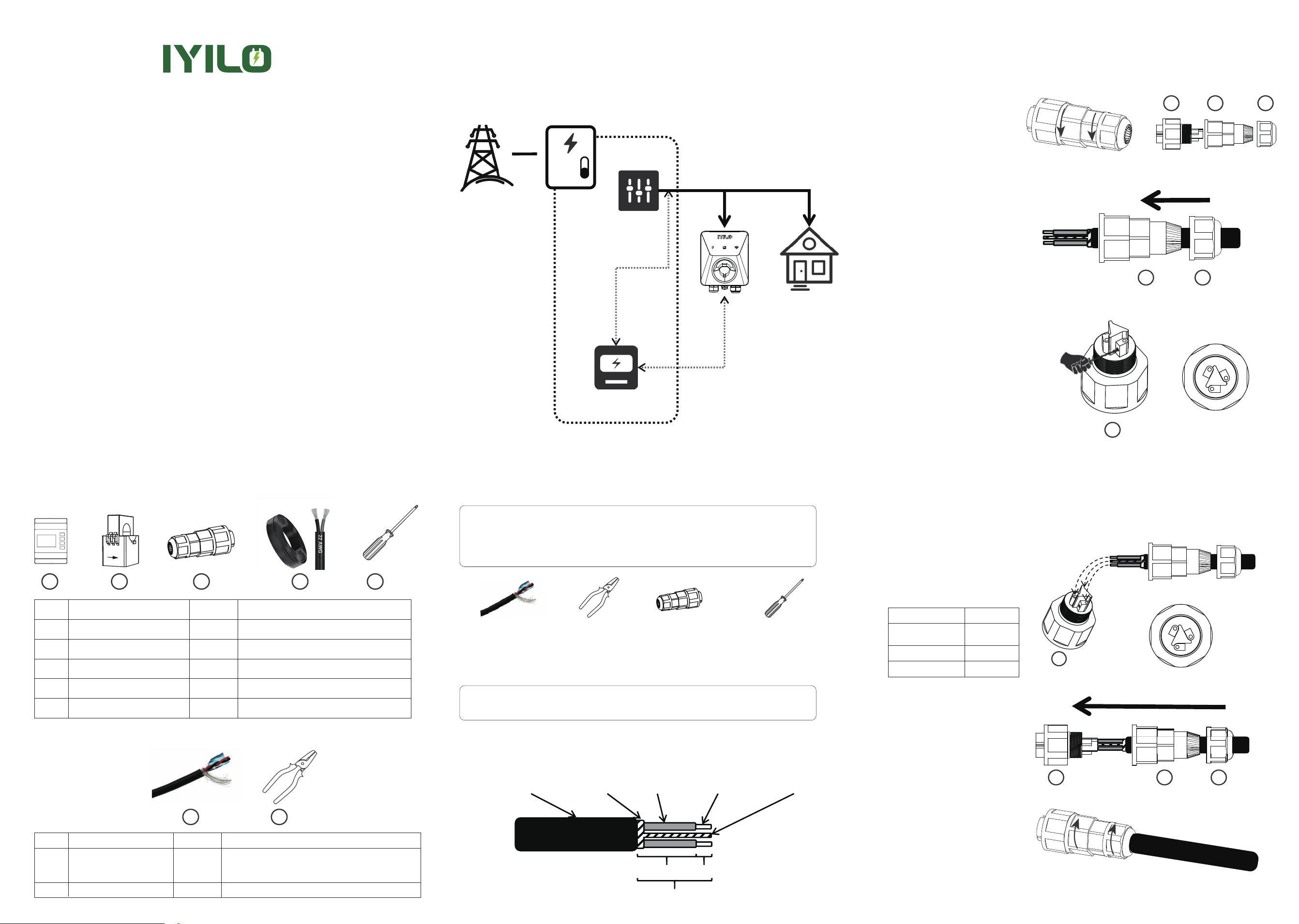
2-1 Remove the quick connector
and twist the two components
counterclockwise to separate it
into three parts.
2-2 As shown in the illustration,
pass the RS485 communication
cable sequentially through
component ③ and component
②.
2-3 Use a screwdriver to turn
the screw in component ①
counterclockwise four full turns to
loosen it. (Turning too many times may
cause the screw to fall out, making it
difficult to handle.)
2-4 Insert the metal conductor part of
the communication
cable into component ①. You
can record the corresponding wire
harness in the table below.
Please connect the shield drain wire
to Terminal 1(Twist the drain wire
strands together before connection)
2-5 Assemble components
② and ①
Table1
2-6 Tighten clockwise to complete
the assembly of the connector
4-EV Charger RS485 Port Installation
Step 1: Communication Cable Stripping Procedure
Step 2: Connect Communication Cable to Quick
Connector
1-1, First, strip approximately 0.8 inches of the communication cable outer jacket.
1-2, Strip approximately 0.2 inches of the communication cable inner insulation.
1-3, Finally, expose 0.2 inches of the metal conductor and 0.6 inches of the inner insulation.
1 2
1
2
3 4 5
No.
RS485 Communication Cable
(20-22AWG)
wire stripper
Used to connect the charger and the meter for data communication
Option 1: 2 Core Twisted Pair Shielded Cable(Recommend)
Option 2: 2 Conductor Stranded Copper Shielded Cable
for RS485 cable preparation
1
2
1
1
Name Quantity Description
Main Breaker
Power line
CT clamp
Energy meter
Communication
RS485 Communication
Cable (x1)
Cable outer
jacket
Shielding
Layer
0.6inch
0.2inch
0.8 inch
cable inner
jacket
Metallic
conductor
Shielding Layer
Drain Wire
Wire Stripper
(x1)
Quick
Connector (x1)
Phillips Screwdriver
(x1)
Other Household
Loads
1
1
1
2
3
1
2
3
2
3
3
1
2
1-WHATS IN THE BOX?
RS485 Communication Cable: Option1: Recommend use 2 Core Twisted Pair Shielded Cable
(two insulated twisted wires with a shielding layer; twist the drain wire into a single strand
before connecting)
Option 2:2 Conductor Stranded Copper Shielded Cable (for short runs under 20 meters)
Note: Use a wire stripper to prepare the communication cable insulation for connection
(improper stripping dimensions may result in water ingress risk).
Component ①Terminal Color
Terminal_1
Shielding Layer
Drain Wire
Terminal_2
Terminal_3
2-Tools and Accessories Required (Not Included)
zzzz
L2
L1
L2 L1
N
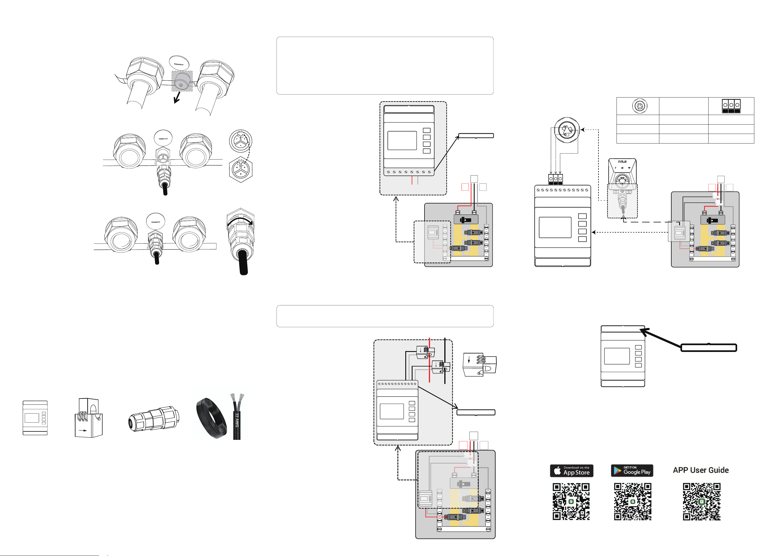
Step 1. Meter Power Supply Installation
Step 2. Connect the CT clamp
1-1 Remove the lower cover panel
of the meter to prepare for wiring.
1-2 Connect the live wire (red):
insert the conductor end into terminal
5 of the meter, and connect the bare
stripped end to the circuit breaker.
1-3 Connect the netural wire (Black):
insert the conductor end into terminal 6
of the meter, and connect the bare
stripped end to the neutral bar
1-4 Power on and test: the screen
lighting up indicates successful meter
power-up.
1-5 Turn off the meter power and
reinstall the cover panel removed in
step 1-1.
Step 3: Connecting the Wired Quick Connector to
the Charging Station
Energy Meter
(x1)
CT Clamps
(x2)
Quick Connector
(x1)
Meter Power Cord
Step 3. RS485 Communication Cable Connection at
the Meter Side
3-1 Route the communication cable, which has already been connected to the charger side, to the
vicinity of the home electrical panel (maximum length should not exceed 300 ft).
3-2 Use wire strippers to remove approximately 0.2 inches (5 mm) of insulation from the cable's
conductor
3-3 Connect the wires according to the following wiring table.
Wire according to the [EV Charger RS485 Port Installation] step 2 table 1.
4-1 Place the upper cover panel back in position
4-2 Turn on the smart meter power supply and open the app.
4-3 In the app, Tap the Advanced ,then selected load balancing
4-4 Enable Dynamic load balancing ; Confirm real-time meter reading appear
4-5 Enter your household breaker rating to finish setup.
▲Important: Check Your Installation Before Use. This meter is designed to work only with the
following electrical setup:
3-wire system (2 hot wires and 1 neutral)
Voltage between phases: 208–240 V
Voltage between phase and neutral: 120 V
Warning: To prevent electric shock or injury, always turn off the main breaker of the
electrical panel before proceeding with the meter installation.
Energy Meter Installation in Electrical Panel Preparation Required:
3-1Remove the Cap from the Plug
3-2 Connect the quick connector
(with communication cable
attached) to the main body of the
charging station. Ensure the plug
protrusion is properly aligned
before securing.
3-3 Tighten the screw of
component ① clockwise to
complete the communication
cable installation
on the charging station side.
5-IYILO Energy Meter Installation Step 4. Assembly Complete
2-1 Remove the upper cover panel
of the meter
Electrical
Panel Inside
2-2 Connect the white wire of the L1
current transformer to terminal 20.
2-3 Connect the black wire of the L1
current transformer to terminal 19.
2-4 Connect the white wire of the L2
current transformer to terminal 18.
2-5 Connect the black wire of the L2
current transformer to terminal 17.
2-6 Clamp the L1 and L2 current
transformers on to the L1 and L2 cables
respectively, ensuring the arrows on the
transformers point downward.
zzzz
L2
L1
N
zzzz
L2
L1
N
1 2 3 4 5 6 7 8
LA NA
L N
1 2 3 4 5 6 7 8
LA NA
9 10 11 12 13 14 15 17 18 1916 20
1 2 3 4 5 6 7 8
LA NA
9 10 11 12 13 14 15 17 18 1916 20
1
2
3
Note: 1.The IYILO EV Charger requires a power supply (less than 0.1A). You can connect the
power cord of the energy meter to an appropriate circuit breaker, which can be shared with an
existing breaker if available.
2.The rated voltage of the meter is 100-277V.
3.The power cord is pre-scored at the bare wire section. Please remove the outer insulation
before use.
Note: When installing the clamp, the arrow should point towards the internal
electrical panel.
Terminal_1
Terminal_2
Terminal_3
Color
Terminal_1
Terminal_2
Terminal_3
Component ①
Download IYILO APP
2 3 1
2 3 1
Shielding Layer Drain Wire