
Operating instructions
RFID UHF evaluation unit
DTE405
DTE505
DTE515
DTP405
DTP505
DTP515
© ifm electronic gmbh • 11642147 / 00 04 / 2026 • en-GB

DTE405 DTE505 DTE515 DTP405 DTP505 DTP515 RFID UHF evaluation unit
2 © ifm electronic gmbh 11642147 / 00 04 / 2026
Contents
1 Preliminary note.............................................................................................................................. 3
1.1 Symbols used....................................................................................................................... 3
1.2 Warnings.............................................................................................................................. 3
1.3 Legal and copyright information............................................................................................ 3
1.4 Open source information ...................................................................................................... 3
1.5 Applicable documents.......................................................................................................... 4
1.6 Change history..................................................................................................................... 4
2 Safety instructions .......................................................................................................................... 5
2.1 Safety symbol on the device ................................................................................................. 5
2.2 Cybersecurity....................................................................................................................... 6
3 Transport, handling and storage ..................................................................................................... 7
4 Intended use .................................................................................................................................. 8
4.1 Application area ................................................................................................................... 8
5 Items supplied ................................................................................................................................ 10
6 Function ......................................................................................................................................... 11
6.1 Device overview ................................................................................................................... 11
6.2 System description............................................................................................................... 12
6.2.1 Overview...................................................................................................................... 13
6.2.2 Status LEDs ................................................................................................................. 13
6.2.3 LED bar ....................................................................................................................... 13
6.2.4 Antenna connectors..................................................................................................... 13
6.2.5 USB port ...................................................................................................................... 14
6.2.6 IO port ......................................................................................................................... 14
6.2.7 Ethernet port................................................................................................................ 14
6.2.8 Voltage supply ............................................................................................................. 14
6.3 Web interface....................................................................................................................... 14
7 Installation ...................................................................................................................................... 16
7.1 Install the device .................................................................................................................. 16
7.2 Eliminate radio interference .................................................................................................. 17
8 Electrical connection ...................................................................................................................... 18
8.1 Wiring................................................................................................................................... 18
8.1.1 USB port ...................................................................................................................... 19
8.1.2 IO port ......................................................................................................................... 19
8.1.3 Ethernet port................................................................................................................ 20
8.1.4 Voltage supply ............................................................................................................. 21
8.1.5 Antenna connectors..................................................................................................... 22
8.2 Connect functional earth ...................................................................................................... 23
8.3 Accessories ......................................................................................................................... 23
9 Operating and display elements...................................................................................................... 25
9.1 Antenna connector ANT LEDs.............................................................................................. 25
9.2 LED bar................................................................................................................................ 25
9.3 USB LED.............................................................................................................................. 25
9.4 Ethernet port LEDs............................................................................................................... 26
9.5 PWR LED ............................................................................................................................. 26
10 Maintenance, repair and disposal ................................................................................................... 28
10.1 Updating the firmware .......................................................................................................... 28
Glossary......................................................................................................................................... 30
RFID UHF evaluation unit DTE405 DTE505 DTE515 DTP405 DTP505 DTP515
© ifm electronic gmbh 11642147 / 00 04 / 2026 3
1 Preliminary note
You will find instructions, technical data, approvals and further information using the QR code on the unit /
packaging or at documentation.ifm.com.
1.1 Symbols used
Requirement
Instruction
Reaction, result
bold Designation of keys, buttons or indications
Cross-reference without link
Cross-reference with link
Important note
Non-compliance may result in malfunction or interference
Information
Supplementary note
1.2 Warnings
Warnings indicate the possibility of personal injury and damage to property. This enables safe product
handling. Warnings are graded as follows:
WARNING
Warning of serious personal injury
If the warning is not observed, fatal and serious injuries are possible.
CAUTION
Warning of minor to moderate personal injury
If the warning is not observed, minor to moderate injuries are possible.
ATTENTION
Warning of damage to property
If the warning is not observed, damage to property is possible.
1.3 Legal and copyright information
© All rights reserved by ifm electronic gmbh. No part of these instructions may be reproduced and used
without the consent of ifm electronic gmbh.
All product names, pictures, companies or other brands used are the property of the respective rights
owners.
1.4 Open source information
For more open source information see: documentation.ifm.com.

DTE405 DTE505 DTE515 DTP405 DTP505 DTP515 RFID UHF evaluation unit
4 © ifm electronic gmbh 11642147 / 00 04 / 2026
1.5 Applicable documents
• Data sheet
• Programming manual
• Software manual
• Package insert “Product information and safety instructions”
• Package insert “Radio approval”
1.6 Change history
Version Subject Date
00 Document newly created 04/2026
RFID UHF evaluation unit DTE405 DTE505 DTE515 DTP405 DTP505 DTP515
© ifm electronic gmbh 11642147 / 00 04 / 2026 5
2 Safety instructions
General
• The device described is a subcomponent for integration into a system.
– The system architect is responsible for the safety of the system.
– The system architect undertakes to perform a risk assessment and to create documentation in ac-
cordance with legal and normative requirements to be provided to the operator and user of the sys-
tem. This documentation must contain all necessary information and safety instructions for the op-
erator, the user and, if applicable, for any service personnel authorised by the architect of the sys-
tem.
• Read this document before setting up the product and keep it during the entire service life.
• The product must be suitable for the corresponding applications and environmental conditions without
any restrictions.
• Only use the product for its intended purpose (
Intended use).
• If the operating instructions or the technical data are not adhered to, personal injury and/or damage to
property may occur.
• The manufacturer assumes no liability or warranty for any consequences caused by tampering with the
product or incorrect use by the operator.
• Installation, electrical connection, set-up, operation and maintenance of the product must be carried
out by qualified personnel authorised by the machine operator.
• Protect the device and the cables against damage.
WARNING
Radio equipment
In general, radio equipment must not be used in the vicinity of petrol stations, fuel depots,
chemical plants or blasting operations.
Do not transport and store any flammable gases, liquids or explosive substances near the
unit.
WARNING
Interference of electronic and medical devices
The device emits high-frequency electromagnetic waves that may interfere with the opera-
tion of electronic devices in the vicinity, including pacemakers, hearing aids and defibrilla-
tors.
People with an implanted pacemaker or other medical devices should only use the device
after consulting their doctor or the manufacturer of the medical device.
If the medical device is affected by the device, do not use the device and maintain a safe
distance between the device and the medical device.
Contact the manufacturer of the device in case of any interference.
2.1 Safety symbol on the device
Safety symbol on the device:
• Adhere to the operating instructions for the safe operation of the device.
• Device of protection class III.

DTE405 DTE505 DTE515 DTP405 DTP505 DTP515 RFID UHF evaluation unit
6 © ifm electronic gmbh 11642147 / 00 04 / 2026
2.2 Cybersecurity
The device has the following security functions:
Design
• Hardened Yocto-Linux distribution
Integrity
• Convenient update of the complete system (recovery system)
• Backup & restore of thesystem configuration
Authentication
• Authentication of the device settings and of firmware updates
Confidentiality
• Browser-based access to the web interface
Restricted data flow
• Factory separation of
IT
and
OT
networks using separate network connections
• Communication of the software components via standard protocols (messaging/
REST
)
ATTENTION
Device operation in an unprotected network environment
Unauthorised read or write access to data is possible.
Unauthorised manipulation of the device function is possible.
Restrict access to authorised users (e.g. password-protected access).

RFID UHF evaluation unit DTE405 DTE505 DTE515 DTP405 DTP505 DTP515
© ifm electronic gmbh 11642147 / 00 04 / 2026 7
3 Transport, handling and storage
Store the device in its original packaging.
When the device is to be stored again, use the original packaging.
Otherwise, provide unused connections with either a mating connector or a protective cap and pack
the device in suitable packaging.
Observe the permissible ambient conditions for the device during storage (
Technical data).
DTE405 DTE505 DTE515 DTP405 DTP505 DTP515 RFID UHF evaluation unit
8 © ifm electronic gmbh 11642147 / 00 04 / 2026
4 Intended use
The multiprotocol-capable
RFID
UHF
evaluation unit DTE405/505/515 or DTP405/505/515 reads active
and passive
ID tags
in different frequency ranges.
The device can read and write ID tags in compliance with the
EPC
Gen2 standard once the appropriate
accessories are connected and the initial configuration has been carried out via the web interface.
The device communicates with the ID tags via transmit and receive antennas. The antennas are connect-
ed to the device’s 4 available antenna ports.
4.1 Application area
Permitted application area:
• Gate applications
• Material flow control in production lines
• Warehouse management by the automatic detection of stored products
• Tank management, order picking or product tracking
• Indoor use. Some of the connected cables can be used outdoors (see fig.).
• In industrial environments
Indoors
PC or
PLC
Power
supply
+24 V DC
USB
RFID UHF
Evaluation
unit
Antenna 1
Antenna 2
Antenna 3
Antenna 4
ID 3
ID 3
ID 3
ID 3
IO (ID 2)
Ethernet
and
PoE
(ID 1b)
Indoors
Outdoors
Fig.1: Indoors and partly outdoors use
The device safety is rated for use under the following operating conditions according to ENIEC62368-1:
• Relative air humidity: maximum 80 %, non-condensing
• Operating altitude: maximum 5000 Nm
• The antenna connections meet ID3 requirements and are suitable for outdoor use.
Incorrect configuration may lead to violation of country-specific limits.
Use the device only with compatible antennas and accessories from ifm.
Observe country-specific requirements for devices, antennas and accessories.

RFID UHF evaluation unit DTE405 DTE505 DTE515 DTP405 DTP505 DTP515
© ifm electronic gmbh 11642147 / 00 04 / 2026 9
The device may only be operated in countries listed in the technical data sheet. In other coun-
tries, protected frequency ranges may be subject to interference.
Observe the radio approval document.
The device’s radio approval information is available online at: documentation.ifm.com
The unit is not approved for safety-related tasks in the field of operator protection.
When installing antennas outdoors:
Observe a maximum cable length of 16 metres between the device and the antenna.
Observe country-specific requirements for protecting the devices against lightning strikes.
Applicable for Europe: EN62305.

DTE405 DTE505 DTE515 DTP405 DTP505 DTP515 RFID UHF evaluation unit
10 © ifm electronic gmbh 11642147 / 00 04 / 2026
5 Items supplied
• Device
• Terminal strip for voltage supply
• Terminal strip for IO port
14
• Package insert “Product information and safety instructions”
• Package insert “Radio approval”
The device is supplied without installation and connection accessories.
Available accessories: Accessories
23
Optimum function is not guaranteed when using accessories from other manufacturers.
RFID UHF evaluation unit DTE405 DTE505 DTE515 DTP405 DTP505 DTP515
© ifm electronic gmbh 11642147 / 00 04 / 2026 11
6 Function
The interfaces between the device and the ID tag are defined according to the GS1 EPCGlobal and ISO
18000-63 standards.
The first steps for reading an ID tag are described in the device’s software manual:
documentation.ifm.com
The integration of the device into moneo is described in the moneo documentation T&T–Track&Trace.
The
? symbol
in moneo provides direct access to the moneo documentation.
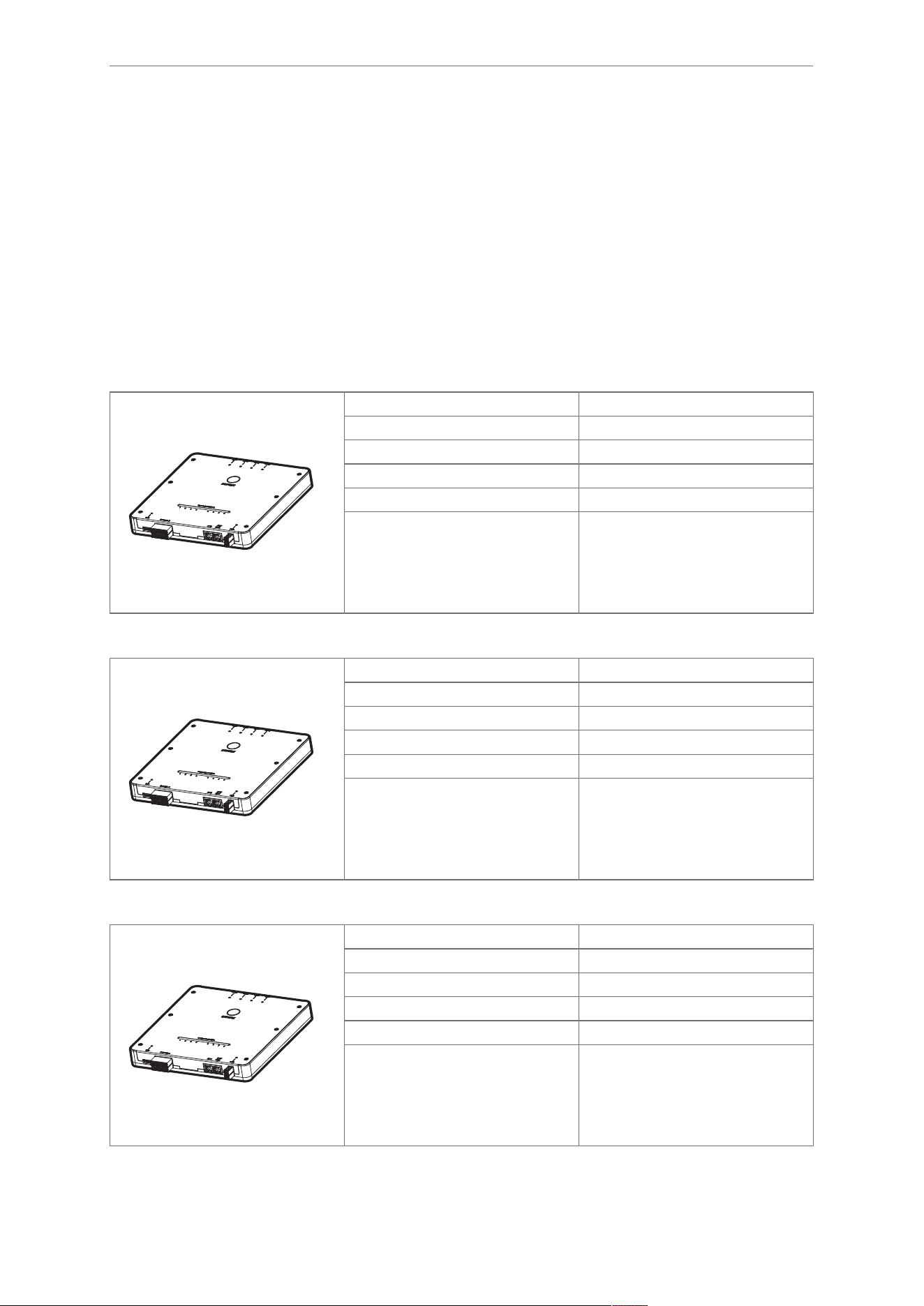
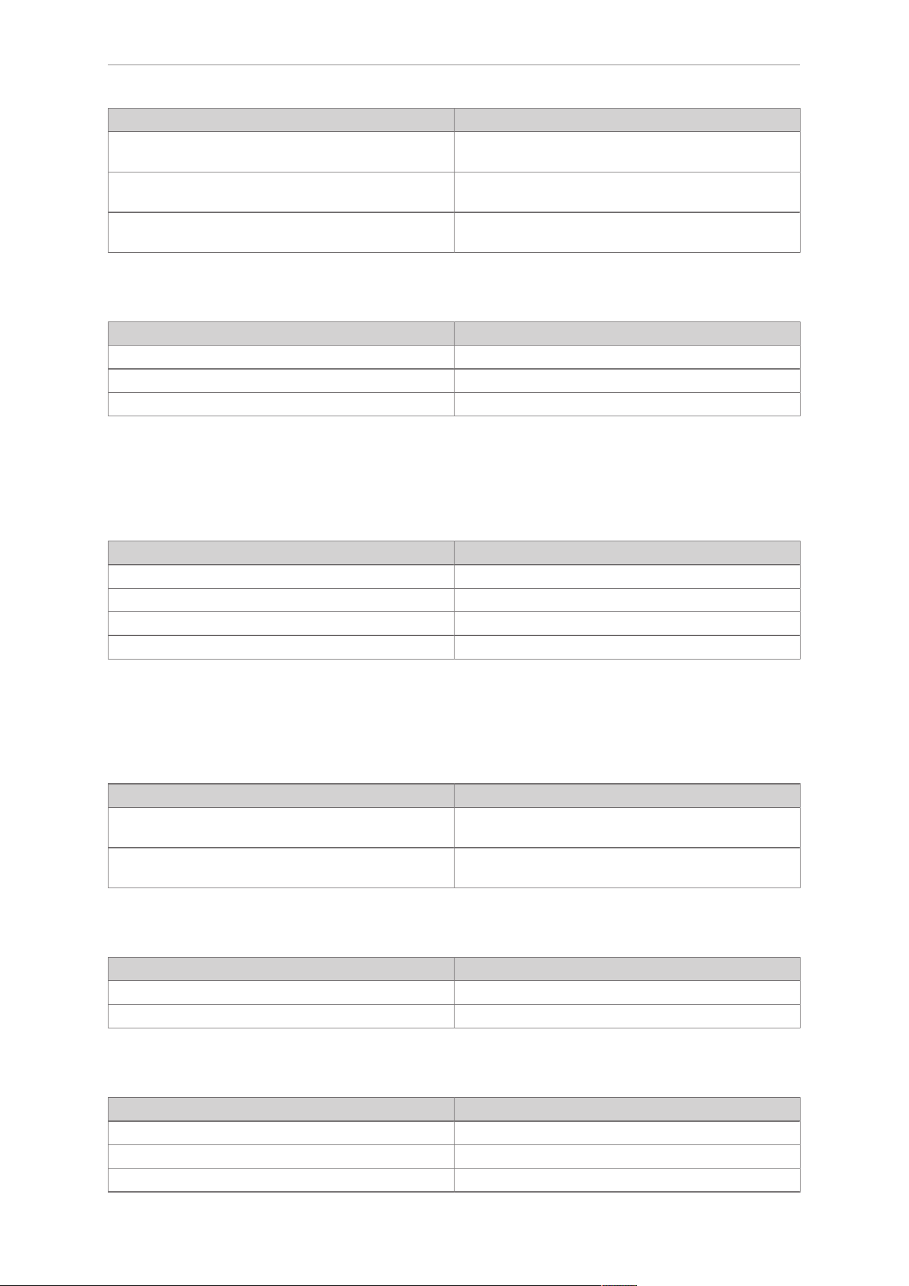
6.1 Device overview
DTE405
Article number: DTE405
Function: RFID UHF evaluation unit
Country: Europe
Frequency range: 865 – 868 MHz
Interfaces: ASCII protocol, IoT Core
Type designation: DTEUHFE ABRWFMRJTB04
DTE505
Article number: DTE505
Function: RFID UHF evaluation unit
Country: USA, Canada
Frequency range: 902 – 928 MHz
Interfaces: ASCII protocol, IoT Core
Type designation: DTEUHFA ABRWFMRJTB04
DTE515
Article number: DTE515
Function: RFID UHF evaluation unit
Country: China
Frequency range: 920.5 – 924.5 MHz
Interfaces: ASCII protocol, IoT Core
Type designation: DTEUHFA ABRWFMRJTB04
DTE405 DTE505 DTE515 DTP405 DTP505 DTP515 RFID UHF evaluation unit
12 © ifm electronic gmbh 11642147 / 00 04 / 2026
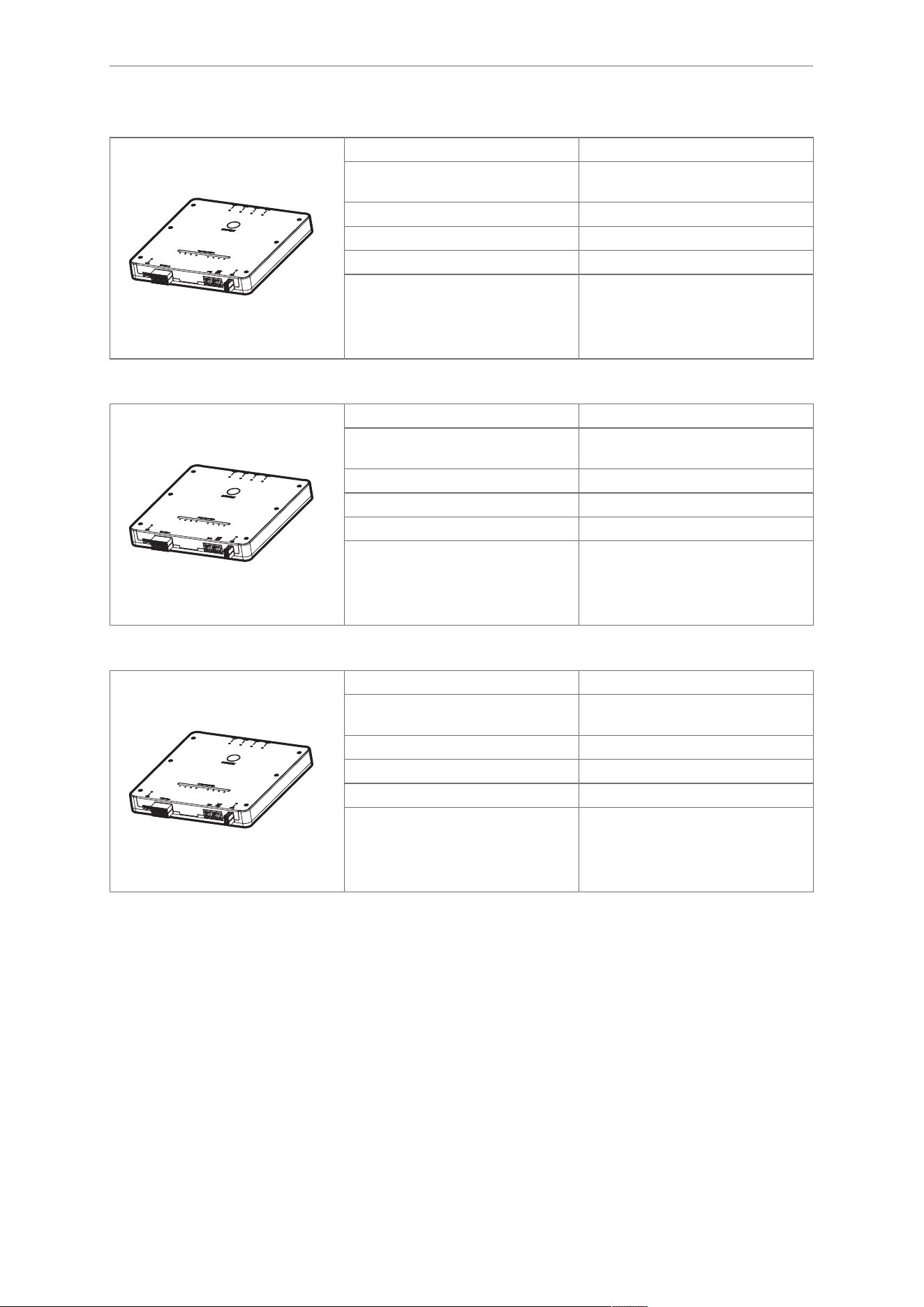
DTP405
Article number: DTP405
Function: RFID UHF evaluation unit
with
PoE++
Country: Europe
Frequency range: 865 – 868 MHz
Interfaces: ASCII protocol, IoT Core
Type designation: DTEUHFE ABRWPOFMRJTB04
DTP505
Article number: DTP505
Function: RFID UHF evaluation unit
with
PoE++
Country: USA, Canada
Frequency range: 902 – 928 MHz
Interfaces: ASCII protocol, IoT Core
Type designation: DTEUHFA ABRWPOFMRJTB04
DTP515
Article number: DTP515
Function: RFID UHF evaluation unit
with
PoE++
Country: China
Frequency range: 920.5 – 924.5 MHz
Interfaces: ASCII protocol, IoT Core
Type designation: DTEUHFA ABRWPOFMRJTB04
6.2 System description
The following sections provide a detailed description of the individual components of the device.

RFID UHF evaluation unit DTE405 DTE505 DTE515 DTP405 DTP505 DTP515
© ifm electronic gmbh 11642147 / 00 04 / 2026 13
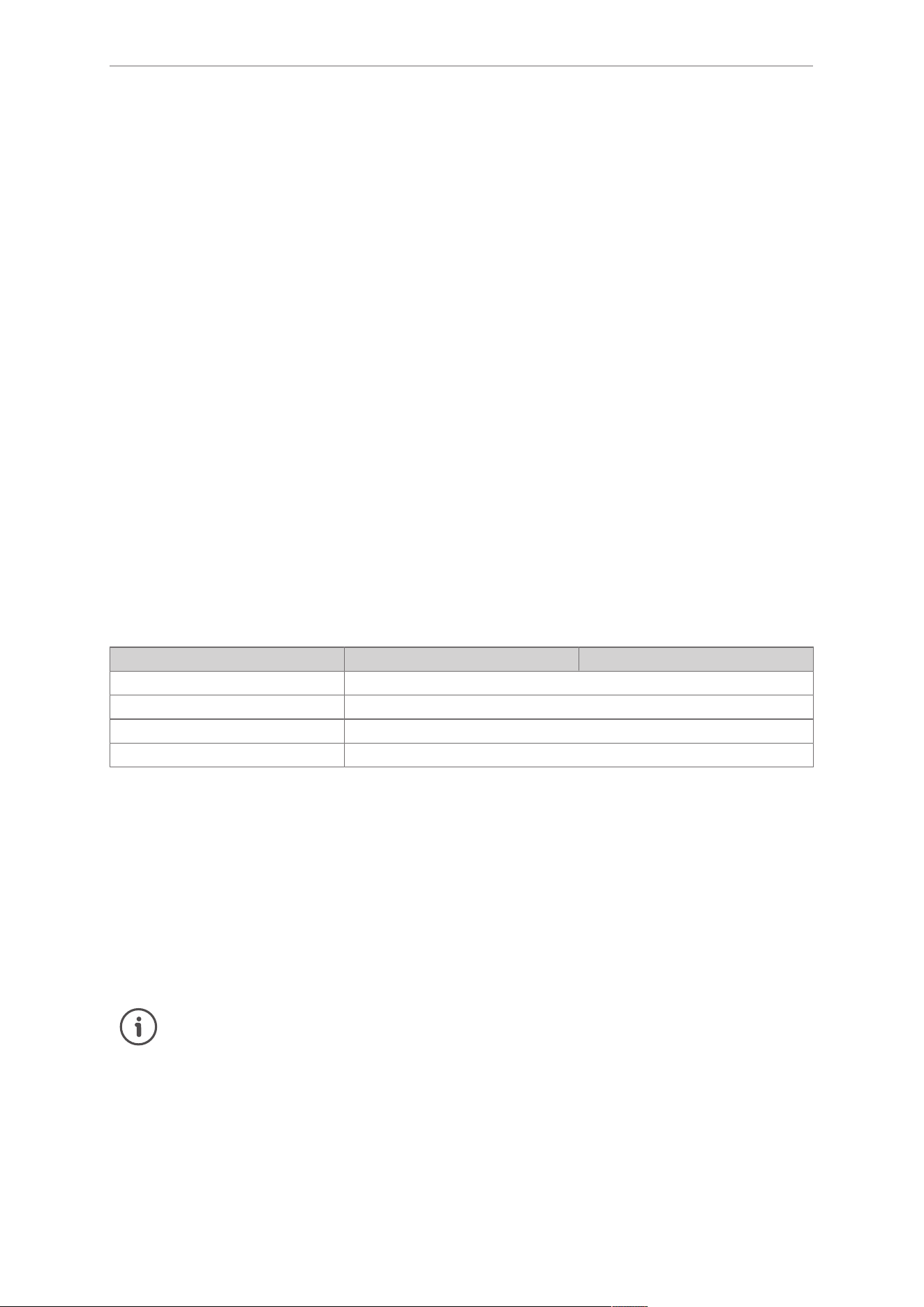
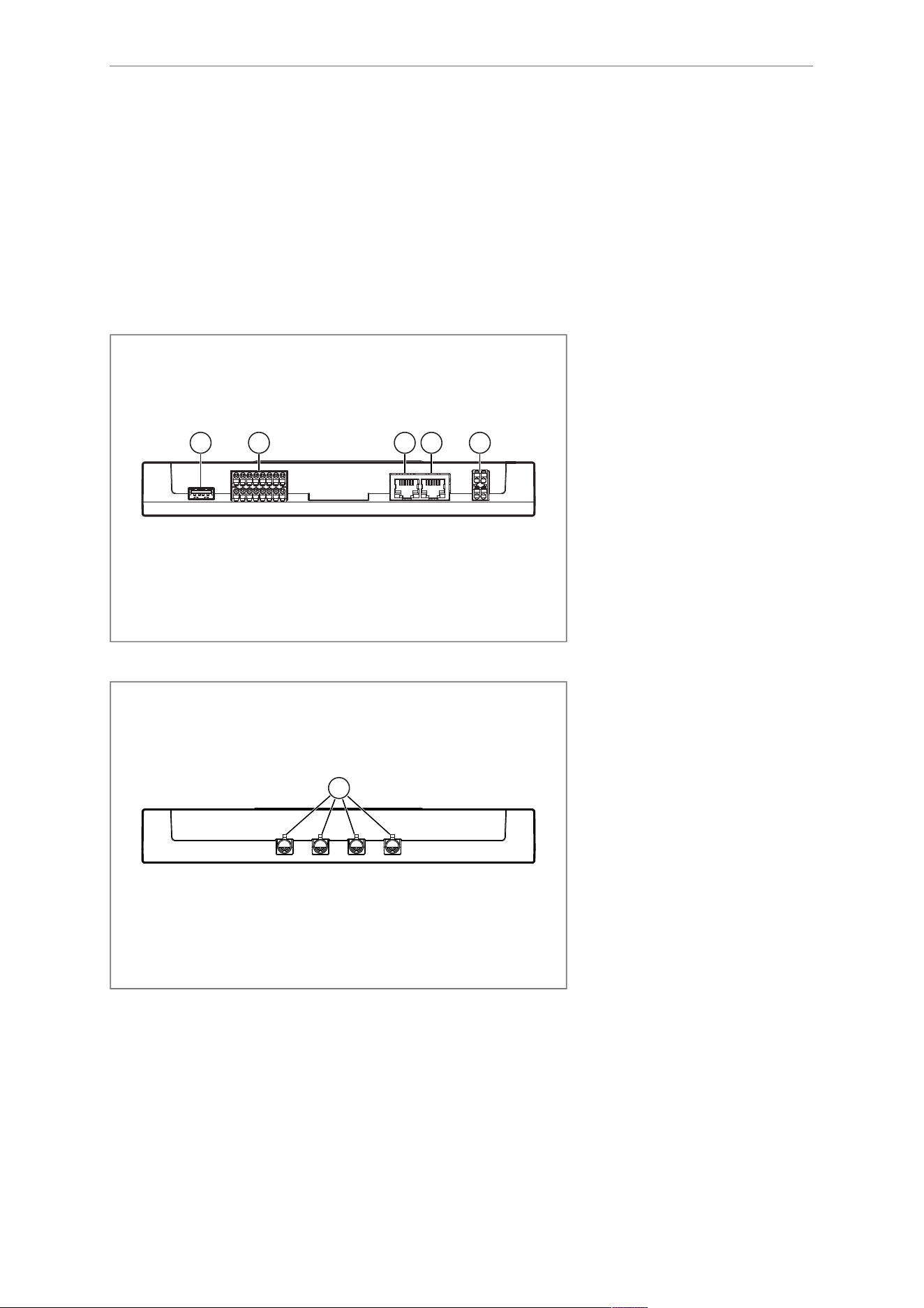
6.2.1 Overview
PWRETH2ETH1IO-Port 1...8USB
1 2 3 4 5 6 7 8
ANT1 ANT2 ANT3 ANT4
1
1 1
3
7
6
5
4
2
7
5
Fig.2: Connections and display elements
1: Status LEDs Status LEDs
13
2: LED bar LED bar
13
3: Antenna connectors 1 to 4 Antenna connectors
13
4: USB port USB port
14
5: IO port 1 to 8 IO port
14
6: Ethernet ports ETH1 and ETH2 Ethernet port
14
7: PWR voltage supply Voltage supply
14
6.2.2 Status LEDs
The device includes multiple status LEDs.
The LEDs indicate the current system status and signal error conditions.
6.2.3 LED bar
The device includes an integrated LED bar. The LED bar consists of 8
RGB
LEDs.
The LED bar can be configured via the web interface.
Details about the web interface are provided in the separate software manual:
documentation.ifm.com
In the default configuration, the LEDs illuminate upon detection of ID tags.
25
6.2.4 Antenna connectors
The device includes 4 antenna connectors for passive UHF antennas. The connectors are implemented as
FAKRA connectors with Z-coding.
Each antenna connector is assigned a status LED.
Individual antennas can be grouped.
DTE405 DTE505 DTE515 DTP405 DTP505 DTP515 RFID UHF evaluation unit
14 © ifm electronic gmbh 11642147 / 00 04 / 2026
6.2.5 USB port
The device includes a USB Type-A port.
The USB port provides the following functions:
• Logging diagnostic data
• Updating the firmware
• Logging data from ID tags
• Importing and exporting configurations using a USB flash drive
6.2.6 IO port
The device includes 8 IO ports for communication with other devices. Via the web interface, the IO ports
can be configured as either inputs or outputs.
The IO ports are designed as a removable terminal block according to IEC 61131-2. The IO ports are not
electrically isolated.
6.2.7 Ethernet port
The device includes 2 RJ45 Ethernet ports. Each Ethernet port is assigned 2 status LEDs. The Ethernet
ports ETH1 and ETH2 connect the device to the IT network infrastructure.
Both Ethernet ports operate in switch mode.
Factory settings
Property ETH1 ETH2
Address assignment Static
IP address 192.168.0.79
Subnet mask 255.255.255.0
Network gateway 0.0.0.0
Power over Ethernet
Devices DTP405, DTP505 and DTP515 can be supplied with power via ETH2 using
PoE++
.
6.2.8 Voltage supply
The device is supplied with voltage via the PWR terminal block.
Power over Ethernet
Devices DTP405, DTP505 and DTP515 can be supplied with power via ETH2 using
PoE++
.
If the device is supplied simultaneously via the PWR terminal block and via PoE++, PoE++ is
used as the preferred voltage supply.
6.3 Web interface
The web interface can be accessed in a web browser via the device’s IP address.
The web interface is used to monitor and configure the device, including:
• Applications running on the device
•
EPC
,
TID
and
user memory area
of ID tags in the detection zone

RFID UHF evaluation unit DTE405 DTE505 DTE515 DTP405 DTP505 DTP515
© ifm electronic gmbh 11642147 / 00 04 / 2026 15
• Detection zone
• Data flow
• Output string
• Digital inputs and outputs
• LEDs
• Service report and log files
• Device settings (network, password, etc.)
• Firmware
The individual functions of the web interface are described in detail in the software manual:
documentation.ifm.com
DTE405 DTE505 DTE515 DTP405 DTP505 DTP515 RFID UHF evaluation unit
16 © ifm electronic gmbh 11642147 / 00 04 / 2026
7 Installation
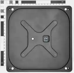
7.1 Install the device
The device is mounted using either the mounting holes or a DIN rail adapter.
1 1
2
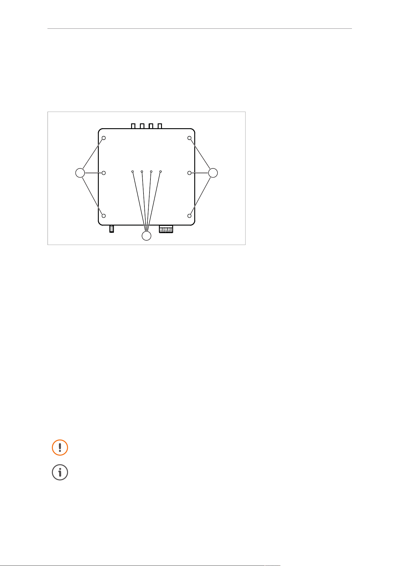
Fig.3: Back of the device with mounting holes and DIN rail adapter
1: M8 mounting holes
2: M4 holes for DIN rail adapter
Mounting holes
Observe the following instructions when using the mounting holes for installation:
Observe the environmental conditions specified in the data sheet.
Mount the device using the M8 mounting holes with at least 4 M8 screws.
Tighten the M8 screws with a tightening torque of 8 Nm and engage them at least 8 mm into the M8
holes.
Use strain relief for cable connections attached to the device.
DIN rail adapter
For DIN rail mounting, the DIN rail adapter E70432 (available as an accessory) is required.
Observe the following instructions when using the DIN rail adapter for installation:
Disconnect power before installation.
Tighten the M4 screws with a tightening torque of 0.8…1 Nm and engage them at least 6 mm into the
M4 holes.
Mount the device on a 35mm DIN rail inside a control cabinet. The control cabinet has to be installed
in accordance with local and national regulations.
Connect the functional earth (FE) to the DIN rail or to the M8 mounting holes on the device.
The DIN rail adapter is not approved for installation in accordance with NEC and cULus.
Mounting note
Optionally, air circulation in the control cabinet and device heating can be optimised:
Mount the device at a minimum distance of 50mm from the top and bottom of the control
cabinet and from adjacent devices.

RFID UHF evaluation unit DTE405 DTE505 DTE515 DTP405 DTP505 DTP515
© ifm electronic gmbh 11642147 / 00 04 / 2026 17
7.2 Eliminate radio interference
The device operates without any radio interference if the following conditions are met:
• The device is used as intended.
8
• The device is properly installed.
16
Application-specific interference
If radio interference occurs in an application:
Reorient the antenna.
Change the position of the antenna.
Adjust filter and functions via the web interface.
The web interface is described in detail in the separate software manual.
Contact the support of the manufacturer.
DTE405 DTE505 DTE515 DTP405 DTP505 DTP515 RFID UHF evaluation unit
18 © ifm electronic gmbh 11642147 / 00 04 / 2026
8 Electrical connection
The device must be connected by a qualified electrician.
Disconnect power before connecting the device.
The device was developed in accordance with the safety standard IEC 62368-1.
The device must be powered only via ES1/PS2 circuits.
8.1 Wiring
1 2 3 4 5
Fig.4: Bottom-side connectors
1: USB port
19
2: IO ports 1 to 8
19
3: Ethernet port ETH1
20
4: Ethernet port ETH2
20
5: PWR voltage supply
21
6
Fig.5: Top-side connectors
6: Antenna connectors 1 to 4
22
RFID UHF evaluation unit DTE405 DTE505 DTE515 DTP405 DTP505 DTP515
© ifm electronic gmbh 11642147 / 00 04 / 2026 19
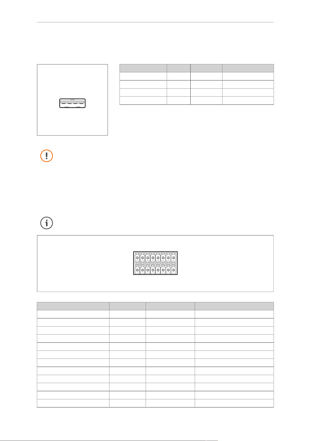
8.1.1 USB port
The device includes a USB Type-A port.
1 2 3 4
Fig.6: USB port pin assignment
Contact designation Function Function type Supply voltage
1 L+ +5 V DC
2 DATA D-
3 DATA D+
4 L-
Use a USB cable with a maximum length of 5 metres.
8.1.2 IO port
The IO ports are designed as a removable terminal block according to IEC 61131-2. The IO ports are not
electrically isolated.
The IO ports are configured via the web interface. Each IO port can be set as either an input or an output.
The web interface is described in the software manual: documentation.ifm.com
B1
B2
B3
B4
B5
B6
B7
B8
A1
A2
A3
A4
A5
A6
A7
A8
Fig.7: Wiring
Contact designation Function Function type Supply voltage
B1 L+ Sensor supply
B2 MP1 DI1/DO1
B3 MP2 DI2/DO2
B4 L-
B5 L+ Sensor supply
B6 MP3 DI3/DO3
B7 MP4 DI4/DO4
B8 L-
A1 L+ Sensor supply
A2 MP5 DI5/DO5
A3 MP6 DI6/DO6
A4 L-
DTE405 DTE505 DTE515 DTP405 DTP505 DTP515 RFID UHF evaluation unit
20 © ifm electronic gmbh 11642147 / 00 04 / 2026
Contact designation Function Function type Supply voltage
A5 L+ Sensor supply
A6 MP7 DI7/DO7
A7 MP8 DI8/DO8
A8 L-
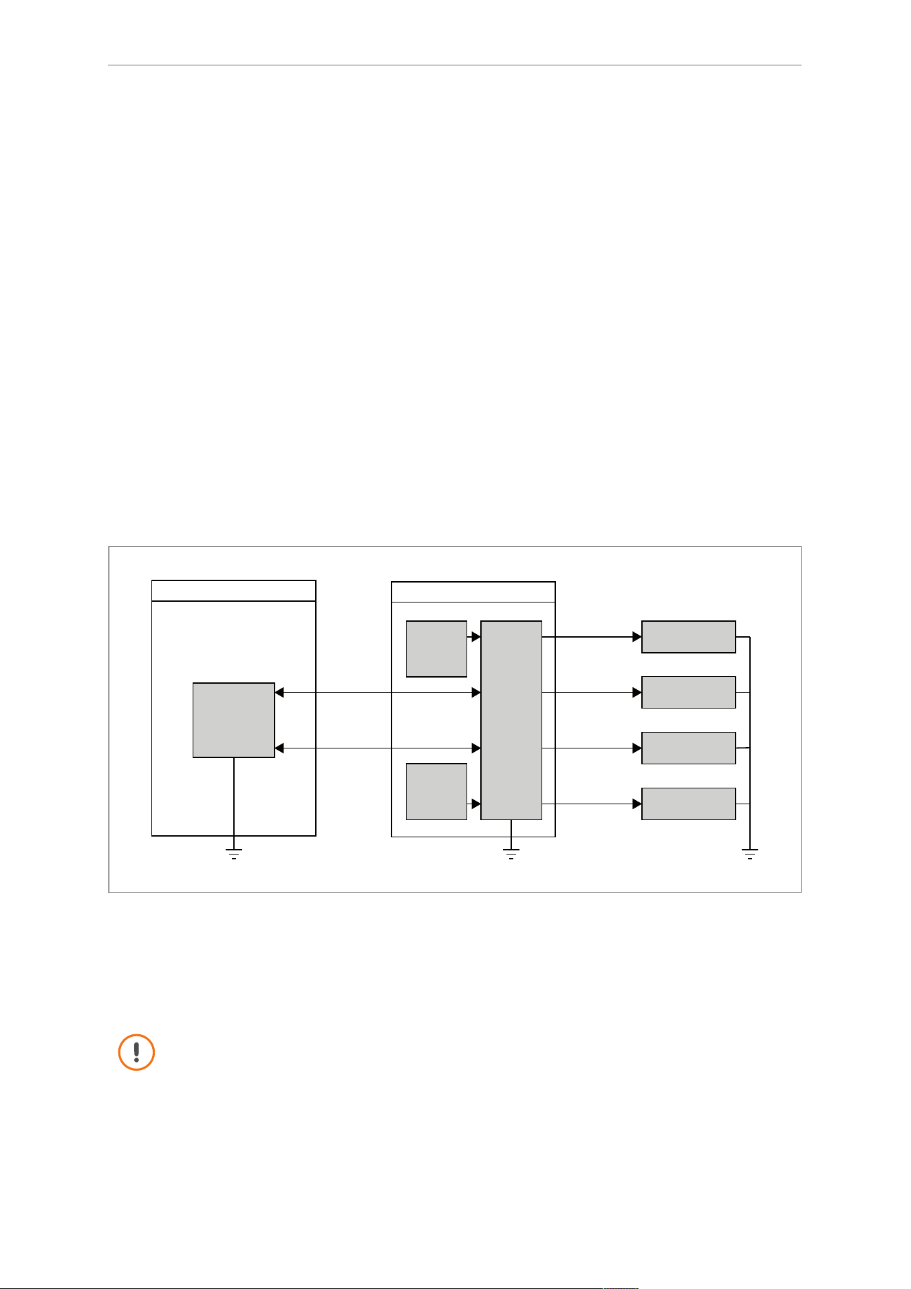
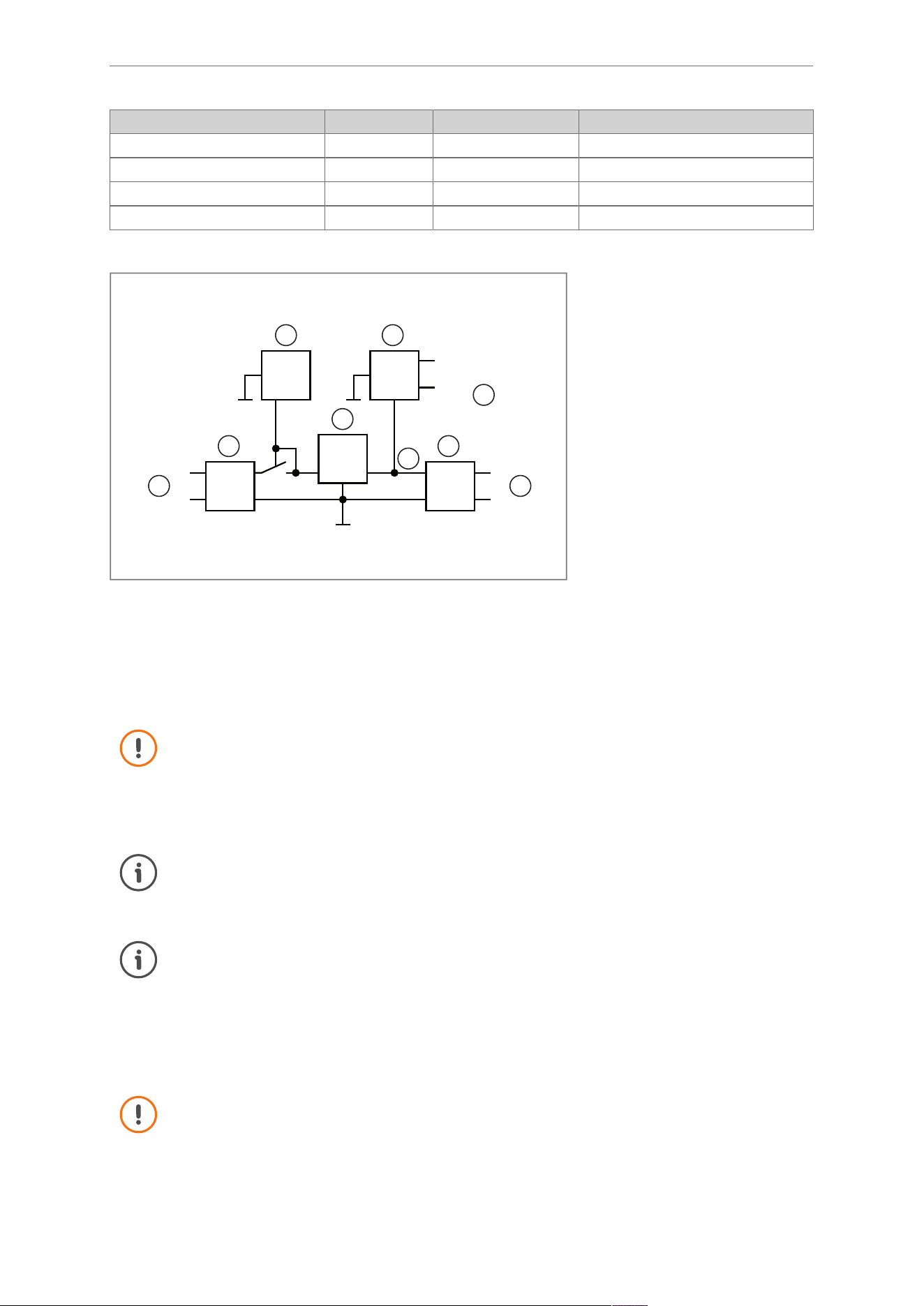
Wiring of the IO ports
Filter Filter
PoE
IO
driver
L+
L-
IO1...8
L+
L-
Limiter
I<600 mA
I<200 mA
1
2 2
3 4
5
6
7
8
Fig.8: Inputs and outputs
1: PWR voltage supply 5: Current limitation of the IO ports
2: Filter 6: Sensor supply
3: PoE++ 7: Current limitation of the current limiter
4: IO port driver 8: Current limiter
The inputs and outputs are designed for max. 30 V DC. For further information please refer to
the technical data sheets.
Limit the load on the digital inputs and outputs to max 0.2A.
The total load of the used digital inputs and outputs and the supply voltage L+ must not ex-
ceed 0.6A.
For cable lengths in indoor and outdoor areas, observe the following requirements:
Cable lengths may exceed 30 m.
Take the voltage drop into account when using long cable lengths.
If the device is supplied simultaneously via the PWR terminal block and via PoE++, PoE++ is
used as the preferred voltage supply.
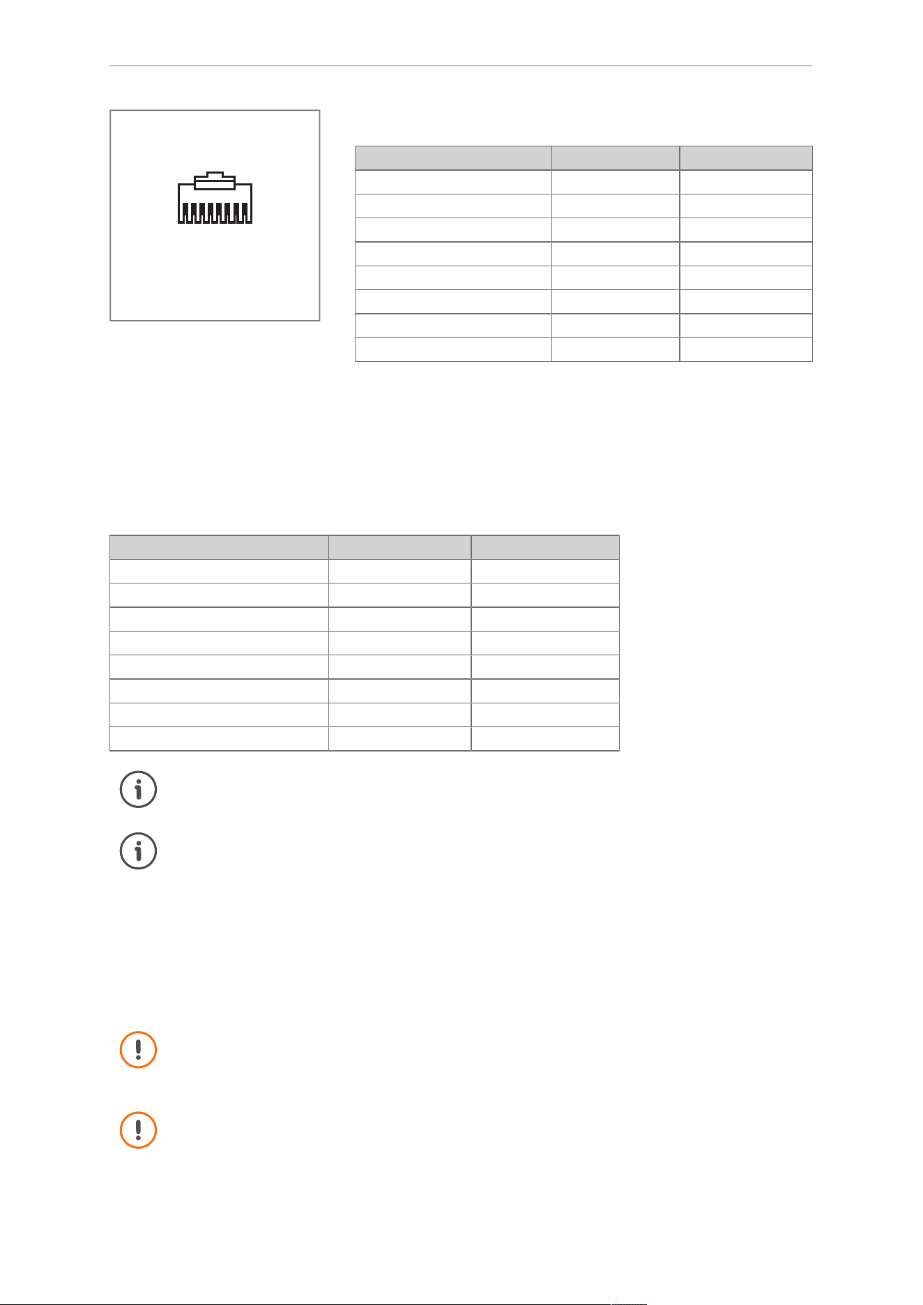
8.1.3 Ethernet port
The Ethernet port is designed as an RJ45 socket.
Only use screened connectors for the Ethernet port.
RFID UHF evaluation unit DTE405 DTE505 DTE515 DTP405 DTP505 DTP515
© ifm electronic gmbh 11642147 / 00 04 / 2026 21
1
2
3
4
5
6
7
8
Fig.9: Ethernet port pin assign-
ment
ETH1
Contact designation Function Function type
1 DATA TX+
2 DATA TX-
3 DATA RX+
4 n.c.
5 n.c.
6 DATA RX-
7 n.c.
8 n.c.
ETH2 with PoE++
The ETH2 Ethernet port is available on the DTE405, DTE505 and DTE515 devices.
The device’s PoE functionality complies with the IEEE802.3 Type 3 powered device (PD) standard.
Using PoE++ requires an Ethernet switch or injector.
The power consumption via ETH2 when using PoE depends on the IO port configuration. The typical pow-
er consumption is specified in the data sheet of the device.
Contact designation Function Function type
1 DATA/PoE++ TX+
2 DATA/PoE++ TX-
3 DATA/PoE++ RX+
4 DATA/PoE++
5 DATA/PoE++
6 DATA/PoE++ RX-
7 DATA/PoE++
8 DATA/PoE++
For cable lengths in indoor and outdoor areas, observe the following requirements:
Use a cable with a maximum length of 100 metres.
If the device is supplied simultaneously via the PWR terminal block and via PoE++, PoE++ is
used as the preferred voltage supply.
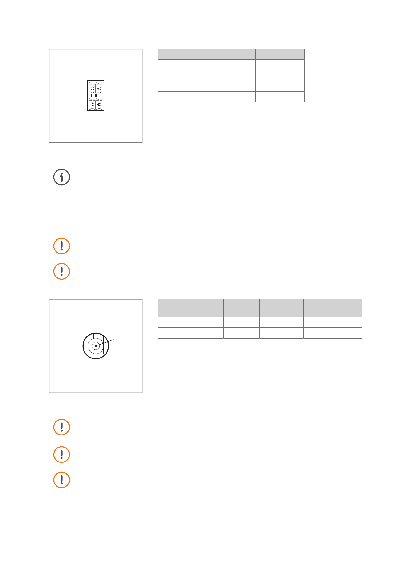
8.1.4 Voltage supply
The voltage supply is designed as a removable terminal block.
The voltage supply can be looped through the device. Depending on the application, the power supply
may limit the maximum number of devices.
The power supply rating must be below 100 W on the secondary side.
Use only LPS (Limited Power Source) or NEC (National Electric Code)Class 2 power sup-
plies for operation.
When connecting the voltage supply, observe the following:
Connect the voltage supply indoors.
Use a cable no longer than 30 metres for the connection.
Connect the cable to the contacts shown in the
Voltage supply pin assignment
figure.
DTE405 DTE505 DTE515 DTP405 DTP505 DTP515 RFID UHF evaluation unit
22 © ifm electronic gmbh 11642147 / 00 04 / 2026
1 2
3 4
Fig.10: Voltage supply pin assign-
ment
Contact designation Function
1 L+
2 L-
3 L+
4 L-
If the device is supplied simultaneously via the PWR terminal block and via PoE++, PoE++ is
used as the preferred voltage supply.
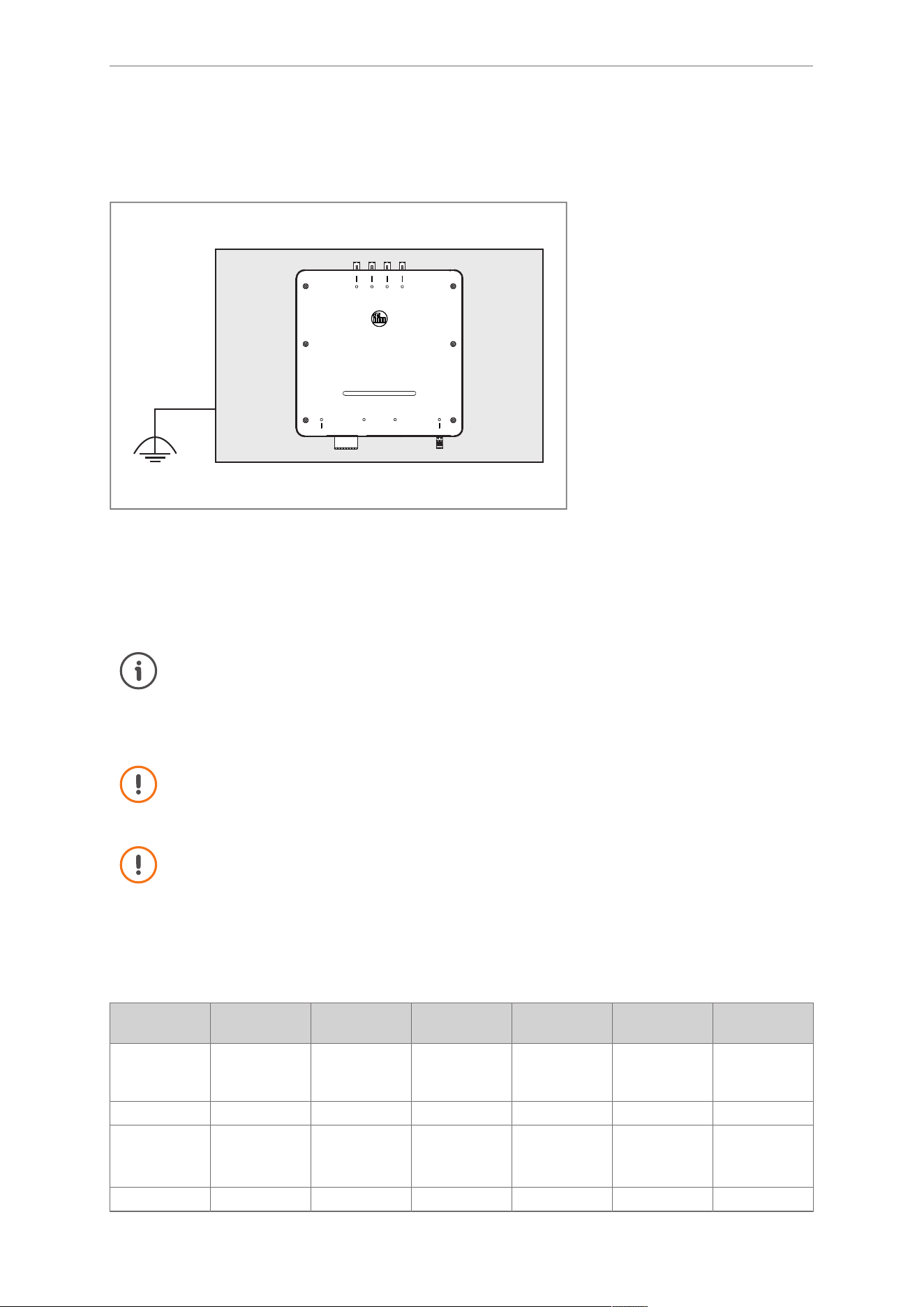
8.1.5 Antenna connectors
The antenna connector is supplied with a voltage of approx. 3.3 V.
Switch off the device before connecting the antenna.
The device is designed for the following antennas:
- Accessories
23
- External antenna with circular polarisation (8.5 dBic, impedance 50Ohm)
1
2
Fig.11: FAKRA antenna connector
pin assignment
Contact designation Function Function type Additional informa-
tion
1 DATA COM RF signal
2 SCREEN FE
Use the device only with compatible antennas and accessories from ifm.
Observe country-specific requirements for devices, antennas and accessories.
Accessories must be selected by a qualified professional.
When installing antennas indoors: Observe a maximum cable length of 30 metres between
the device and the antenna.
When installing antennas outdoors: Observe a maximum cable length of 16 metres between
the device and the antenna.
RFID UHF evaluation unit DTE405 DTE505 DTE515 DTP405 DTP505 DTP515
© ifm electronic gmbh 11642147 / 00 04 / 2026 23
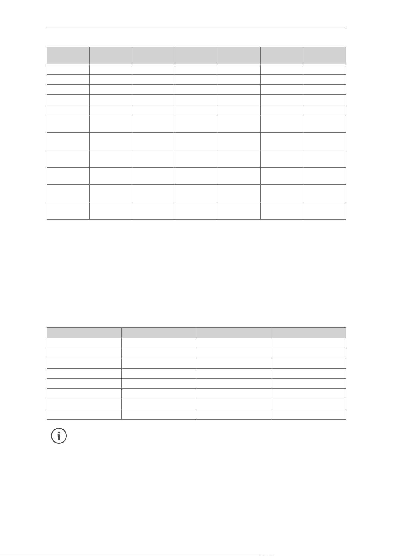
8.2 Connect functional earth
To ensure interference-free operation, the device must be connected to an earth potential that is free from
external voltage.
PWR
ETH2ETH1IO-Port 1...8USB
1 2 3 4 5 6
7
8
ANT1 ANT2 ANT3 ANT4
RUN ERR
Fig.12: Mounting plate with mounted device
Connect the mounting plate to the functional earth:
Connect one of the M8 mounting holes on the back of the device to the mounting plate.
Tighten the M8 screw with a tightening torque of 8 Nm and engage it at least 8 mm into the M8 hole.
Connect the mounting plate to an earth potential free from external voltage.
Alternatively, the connection to an earth potential free from external voltage can be made via
the DIN rail adapter E70432.
16
8.3 Accessories
Using accessories not listed (cable, power supply and antennas) may result in exceeding legal
limits.
Accessories must be selected and installed by a qualified professional.
Incorrect configuration may lead to violation of country-specific limits.
Use the device only with compatible antennas and accessories from ifm.
Observe country-specific requirements for devices, antennas and accessories.
RFID UHF antennas
The antennas are optimised for RFID applications. The antenna gain values from the technical data sheet
are stored in the device firmware.
Article Country ap-
proval
Frequency
range [MHz]
Gain [dBic] Antenna de-
tection
Connection Impedance
ANT805
1
EU/ USA/
Canada/ Chi-
na
865…928 -30 No TNC 50 Ω
ANT810
1
EU 865…868 -15 No TNC 50 Ω
ANT815 EU/ USA/
Canada/ Chi-
na
865…868
902…928
EU:-10
USA/ Cana-
da/ China:-12
No TNC 50 Ω
ANT820 EU 865…868 2.5 No TNC 50 Ω
DTE405 DTE505 DTE515 DTP405 DTP505 DTP515 RFID UHF evaluation unit
24 © ifm electronic gmbh 11642147 / 00 04 / 2026
Article Country ap-
proval
Frequency
range [MHz]
Gain [dBic] Antenna de-
tection
Connection Impedance
ANT850 EU 865…868 8.5 Yes TNC 50 Ω
ANT855 EU 865…868 8.5 Yes FAKRA 50 Ω
ANT860 EU 865…868 8.5 No TNC 50 Ω
ANT870 EU 865…868 2.5 Yes TNC 50 Ω
ANT875 EU 865…868 2.5 Yes FAKRA 50 Ω
ANT920 USA/ Cana-
da/ China
902…928 2.5 No TNC 50 Ω
ANT950 USA/ Cana-
da/ China
902…928 8.5 Yes TNC 50 Ω
ANT955 USA/ Cana-
da/ China
902…928 8.5 Yes FAKRA 50 Ω
ANT960 USA/ Cana-
da/ China
902…928 8.5 No TNC 50 Ω
ANT970 USA/ Cana-
da/ China
902…928 2.5 Yes TNC 50 Ω
ANT975 USA/ Cana-
da/ China
902…928 2.5 Yes FAKRA 50 Ω
1
ANT805 and ANT810, in combination with the evaluation unit, meet the requirements of the EN 301489-3
standard. Both antennas do not meet the interference immunity requirements of the IEC 61000-6-4 standard.
Antenna detection
The device can detect antennas with antenna detection (see previous table). If an antenna with antenna
detection is configured, the device automatically checks whether the correct antenna is connected. If a
different antenna is used, an error message is displayed.
While antenna detection helps ensure compliance with legal regulations, the selection of appropriate ac-
cessories must still be carried out and installed by a qualified professional.
Cable
The listed cables can be used in all countries.
Article Type Country approval Connection
E80520 Coaxial cable All countries FAKRA / FAKRA
E80521 Coaxial cable All countries FAKRA / FAKRA
E80522 Coaxial cable All countries FAKRA / FAKRA
E80523 Coaxial cable All countries FAKRA / FAKRA
E80524 Coaxial cable All countries FAKRA / TNC
E80525 Coaxial cable All countries FAKRA / TNC
E80526 Coaxial cable All countries FAKRA / TNC
E80527 Coaxial cable All countries FAKRA / TNC
The attenuation values of the cables can be found in their technical data sheets and in the de-
vice firmware.
RFID UHF evaluation unit DTE405 DTE505 DTE515 DTP405 DTP505 DTP515
© ifm electronic gmbh 11642147 / 00 04 / 2026 25
9 Operating and display elements
The device includes multiple status LEDs.
The LEDs indicate the current system status and signal error conditions.
The device features an additional programmable LED bar.
9.1 Antenna connector ANT LEDs
An ANT LED is assigned to each antenna connector.
LED Description
Off The antenna is not configured and not active.
Lights green at 1 Hz The antenna is configured and the
RF field
is switched
off.
Lights green The antenna and the
RF field
are configured. The device
is prepared for detecting ID tags in the field.
Lights yellow The antenna and
RF field
are configured and at least one
ID tag is detected.
Lights red at 1 Hz The configuration in the device does not match the con-
nected antenna.
The antenna is not connected or the connection is inter-
rupted.
The antenna’s article number does not match the config-
uration.
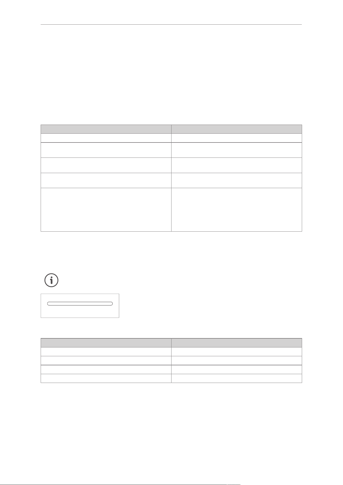
9.2 LED bar
The LED bar can be configured via the web interface.
Details about the web interface are provided in the separate software manual:
documentation.ifm.com
1 2 3 4 5 6 7 8
Fig.13: LED bar
In the default configuration, the LEDs behave as follows:
LED Description
LED 1 lights 1 ID tag detected at antenna connector1
LEDs 1 and 2 light 2 ID tags detected at antenna connector1
.. ..
LEDs 1, 2, 3, 4, 5, 6, 7 and 8 light 8 ID tags detected at antenna connector1
Firmware update
The firmware update is indicated via the LED bar.
9.3 USB LED
The USB port is assigned a USB LED.
DTE405 DTE505 DTE515 DTP405 DTP505 DTP515 RFID UHF evaluation unit
26 © ifm electronic gmbh 11642147 / 00 04 / 2026
LED Description
Lights green The USB interface is used for saving logging data or con-
figuration changes.
Lights red at 1 Hz USB connection error. Check the USB stick used and
observe any error messages displayed by the device.
Lights red The device has detected a critical error on the USB port.
Contact the device manufacturer.
Firmware update
The firmware update is indicated by the USB LED when the update is performed via USB.
LED Description
Lights green at 1 Hz The firmware is being updated.
Off The firmware has been successfully updated.
Lights red at 1 Hz Firmware update failed due to an error.
9.4 Ethernet port LEDs
The status of an Ethernet port is indicated via 2 LEDs.
LED Description
LED LNK lights green Ethernet connection established
LED LNK does not light green Ethernet connection not established
LED ACT lights yellow Data is being transmitted
LED ACT does not light yellow No data is being transmitted
9.5 PWR LED
Voltage supply
The PWR LED indicates the status of the voltage supply.
LED Description
Off The device is not operational. No voltage supply con-
nected or supply voltage below 13V.
Lights green The device is ready for operation and the supply voltage
is within the valid range.
PoE
The PWR LED indicates the status of
PoE++
when PoE++ is used as the voltage supply.
LED Description
Off No voltage supply via PoE++.
Lights green The voltage supply via PoE++ is connected and OK.
Firmware update
The firmware update is indicated via the PWR LED.
LED Description
Lights green at 1 Hz The firmware is being updated.
Lights green The firmware has been successfully updated.
Lights red at 1 Hz Firmware update failed due to an error.

RFID UHF evaluation unit DTE405 DTE505 DTE515 DTP405 DTP505 DTP515
© ifm electronic gmbh 11642147 / 00 04 / 2026 27
Device status
In the event of critical errors, the status of the device is indicated by the PWR LED.
LED Description
Lights red Critical internal device error.
Contact the manufacturer, ifm electronic gmbh.

DTE405 DTE505 DTE515 DTP405 DTP505 DTP515 RFID UHF evaluation unit
28 © ifm electronic gmbh 11642147 / 00 04 / 2026
10 Maintenance, repair and disposal
The unit is maintenance-free.
Contact ifm in case of malfunction.
Do not open the housing as the unit does not contain any components which can be maintained by the
user. The unit must only be repaired by the manufacturer.
Clean the device using a dry cloth.
Dispose of the unit in accordance with the national environmental regulations.
10.1 Updating the firmware
The following display elements signal an ongoing firmware update:
LED bar
The firmware update is indicated via the LED bar.
USB LED
The firmware update is indicated by the USB LED when the update is performed via USB.
LED Description
Flashes green at 1 Hz The firmware is being updated.
Off The firmware has been successfully updated.
Flashes red at 1 Hz Firmware update failed due to an error.
PWR LED
The firmware update is indicated via the PWR LED.
LED Description
Flashes green at 1 Hz The firmware is being updated.
Lights green The firmware has been successfully updated.
Flashes red at 1 Hz Firmware update failed due to an error.

RFID UHF evaluation unit DTE405 DTE505 DTE515 DTP405 DTP505 DTP515
© ifm electronic gmbh 11642147 / 00 04 / 2026 29
List of figures
Fig. 1 Indoors and partly outdoors use ............................................................................................ 8
Fig. 2 Connections and display elements ........................................................................................ 13
Fig. 3 Back of the device with mounting holes and DIN rail adapter ................................................. 16
Fig. 4 Bottom-side connectors ........................................................................................................ 18
Fig. 5 Top-side connectors.............................................................................................................. 18
Fig. 6 USB port pin assignment....................................................................................................... 19
Fig. 7 Wiring.................................................................................................................................... 19
Fig. 8 Inputs and outputs ................................................................................................................ 19
Fig. 9 Ethernet port pin assignment................................................................................................. 21
Fig. 10 Voltage supply pin assignment .............................................................................................. 22
Fig. 11 FAKRA antenna connector pin assignment............................................................................ 22
Fig. 12 Mounting plate with mounted device...................................................................................... 23
Fig. 13 LED bar................................................................................................................................. 25

DTE405 DTE505 DTE515 DTP405 DTP505 DTP515 RFID UHF evaluation unit
30 © ifm electronic gmbh 11642147 / 00 04 / 2026
Glossary
EPC
The EPC (Electronic Product Code) is a
unique identification number based on an in-
ternationally used key and code system. The
EPC is used to uniquely mark and identify
products, logical units, equipment, docu-
ments, etc.
ID tag
An ID tag is used to identify objects. A read/
write device is used to read the ID tag via a
high-frequency radio signal. An ID tag con-
sists of an antenna, an analogue circuit for re-
ceiving and transmitting (transceiver), a digi-
tal circuit and a non-volatile memory.
IT
Information Technology (IT) comprises tech-
nical resources used to create, manage and
transmit digital information. Due to increasing
digitalisation and IoT, OT and IT are merging.
OT
Operational Technology (OT) comprises
hardware and software used to control and
monitor physical machines, systems and pro-
cesses. Due to increasing digitalisation and
IoT, OT and IT are merging.
PoE++
Power over Ethernet (PoE) can supply devic-
es with operating voltage via the Ethernet
port. This eliminates the need to connect the
device to a separate power supply. The pow-
er cable can thus be omitted. Devices with
POE++ can receive up to 51W. The maxi-
mum output power of the PSE (Power Sourc-
ing Equipment) is 60W.
REST
Representational State Transfer (REST) is
based on the HTTP protocol and is a popular
architectural style for request and response
communication.
RF field
The RF field refers to electromagnetic waves
and their transmission at 13.56MHz. The op-
erating frequency of the RF field may deviate
from 13.56MHz.
RFID
RFID is a technology for automatic and con-
tactless identification and localisation of ob-
jects. An RFID system consists of an ID tag
and a read/write device. The ID tag contains
an identifying code and is attached to an ob-
ject. The read/write device can write and read
the code of the ID tag.
RGB
RGB refers to a colour space that is created
by the additive mixing of the primary colours
red, green and blue.
TID
The transponder ID is a globally unique identi-
fication number of the ID tag. It is assigned by
the chip manufacturer of the ID tag during
production and cannot be changed after-
wards. The TID is stored in the TID storage
area of the ID tag.
UHF band
The UHF (Ultra High Frequency) band refers
to electromagnetic waves with a wavelength
of 1 to 10dm. This corresponds to a frequen-
cy band of approx. 300MHz to 3GHz.
USER memory area
The USER memory area is a memory area on
the ID tag for application-specific data.

Funkzulassung
Radio approval
Agrément radio
Radyo onayı
无线电批准
DTE405
DTE505
DTE515
DTP405
DTP505
DTP515
ifm electronic gmbh • Friedrichstraße 1 • 45128 Essen • Germany
11642402 / 0004 / 2026
80334382 / 00
ð

2
Europäische Union / European Union / L‘Union Europe
Deutsch
DTE405 / DTP405
Vor Inbetriebnahme die Bedienungsanleitung lesen und während der
Einsatzdauer aufbewahren.
• Hiermit erklärt die ifm electronic GmbH, dass die Funkanlagentypen
DTE405 und DTP405 der Richtlinie 2014/53/EU entsprechen.
• Der vollständige Text der EU-Konformitätserklärung, Technische Daten,
Anleitungen, Zulassungen, Kontakte und weitere Informationen unter
documentation.ifm.com.
WARNUNG!Der Betrieb dieses Gerätes kann Funkstörungen in
Wohngebieten verursachen.
Das Gerät hat eine Arbeitsfrequenz von 865 bis 868MHz und eine
maximale Sendeleistung von 32,9dBmERP.
Die zulässigen Antennen und Kabel sind in der Betriebsanleitung
beschrieben. Für benutzerdefinierte Antennen sind folgende
Konfigurationen erlaubt:
• Patchantennen mit zirkularer Polarisation und einem maximalen
Gewinn von 8,5dBic.
• Quadrifilare Spiralantennen mit zirkularer Polarisation und einem
maximalen Gewinn von 2,5dBic.
• Die eingesetzten Antennen müssen die gleiche zirkulare
Polarisationsrichtung verwenden.
Andere Konfigurationen sind strengstens verboten.
Aufgrund der Human-Exposure-Vorschrift einen Mindestabstand von 30cm
zwischen den Antennen und Personen einhalten.
Das System bestehend aus der RFID UHF Auswerteeinheit,
Verbindungskabel und Antennen sendet Funkwellen aus, die
möglicherweise den Betrieb von elektronischen Geräten in der Nähe
beeinträchtigen, darunter Herzschrittmacher, Hörelemente und
Defibrillatoren. Wenn Sie einen Herzschrittmacher oder ein anderes
implantiertes Medizinprodukt haben, verwenden Sie das System nicht ohne
vorherige Rücksprache mit Ihrem Arzt oder dem Hersteller Ihres
Medizinprodukts. Halten Sie einen Sicherheitsabstand zwischen den

3
Antennen und Ihren Medizinprodukten ein und sehen Sie von der weiteren
Verwendung ab, wenn Sie eine dauerhafte Beeinträchtigung Ihres
Medizinprodukts beobachten.
English
DTE405 / DTP405
Read the operating instructions before set-up and keep them for the
duration of use.
• ifm electronic gmbh hereby declares that the radio equipment types
DTE405 and DTP405 are in compliance with Directive 2014/53/EU.
• The full text of the EU Declaration of Conformity, technical data,
instructions, approvals, contacts and further information at
documentation.ifm.com.
WARNING!The operation of this device can cause radio interference
in residential areas.
The device has an operating frequency of 865to 868MHz and a maximum
transmitter power of 32,9dBmERP.
The permitted antennas and cables are described in the operating
instructions. The following configurations are permitted for user-defined
antennas:
• Patch antennas with circular polarisation and a maximum gain of
8.5dBic.
• Quadrifilar spiral antennas with circular polarisation and a maximum
gain of 2.5dBic.
• The antennas used must have the same circular polarisation direction.
Any other configurations are strictly prohibited.
In accordance with human exposure regulations, a minimum distance of
30cm must be maintained between the antennas and people.
The system, comprising the UHF RFID evaluation unit, jumper cables and
antennas, emits radio waves that may interfere with the operation of nearby
electronic devices, including pacemakers, hearing aids and defibrillators. If
you have a pacemaker or other implanted medical device, do not use the
system without first consulting your doctor or the manufacturer of the
medical device. Maintain a safe distance between the antennas and your
medical device and refrain from further use if you observe permanent
impairment of your medical device.

4
Français
DTE405 / DTP405
Lire la notice d‘utilisation avant l‘utilisation et conserver-la pendant toute la
durée d‘utilisation.
• ifm electronic gmbh déclare par la présente que les équipements radio
DTE405 et DTP405 correspondent à la directive 2014/53/EU.
• Vous trouverez le texte intégral de la déclaration de conformité de l‘UE,
les données techniques, les instructions, les homologations, les
contacts et d‘autres informations sur le site documentation.ifm.com.
AVERTISSEMENT!Le fonctionnement de cet appareil peut causer des
interférences radio dans les zones résidentielles.
L'appareil a une fréquence de fonctionnement de 865à868MHz et une
puissance d'émission maximale de 32,9dBmERP.
Les antennes et câbles autorisés sont décrits dans la notice d’utilisation.
Pour les antennes personnalisées, les configurations suivantes sont
autorisées :
• Antennes patch à polarisation circulaire avec un gain maximal de
8,5dBic.
• Antennes spirales quadrifilaires à polarisation circulaire et avec un gain
maximal de 2,5dBic.
• Les antennes utilisées doivent avoir la même direction de polarisation
circulaire.
Toute autre configuration est strictement interdite.
Conformément à la réglementation relative à l’exposition humaine, une
distance minimale de 30cm doit être respectée entre les antennes et les
personnes.
Le système, composé d’un boîtier de contrôle RFID UHF, de câbles de
raccordement et d’antennes, émet des ondes radio qui peuvent interférer
avec le fonctionnement des appareils électroniques situés à proximité,
notamment les stimulateurs cardiaques, les appareils auditifs et les
défibrillateurs. Si vous avez un stimulateur cardiaque ou un autre dispositif
médical implanté, n’utilisez pas le système sans avoir consulté au préalable
votre médecin ou le fabricant de votre dispositif médical. Maintenez une
distance de sécurité entre les antennes et votre dispositif médical, et
cessez toute utilisation si vous constatez une altération permanente du
dispositif médical.

5
Türkiye
Türkçe
Kurulumdan önce kullanma talimatlarını okuyunuz ve bunları ürünün tüm
kullanım süresince saklayınız.
• ifm electronic gmbh, DTE405 ve DTP405 tip telsiz cihazlarının 2014/53/
EU sayılı Direktif ile uyumlu olduğunu beyan eder.
• EU Uygunluk Beyanı'nın tam metni, teknik veriler, talimatlar, onaylar,
iletişim bilgileri ve daha fazla bilgi burada bulunabilir:
documentation.ifm.com.
UYARI! Bu cihazın çalışması, yerleşim alanlarında radyo parazitine
neden olabilir.
Cihaz 865 ila 868MHz çalışma frekansına ve 32,9dBmERP maksimum
transmitter gücüne sahiptir.
İzin verilen antenler ve kablolar kullanım kılavuzunda açıklanmıştır.
Kullanıcı tanımlı antenler için aşağıdaki konfigürasyonlara izin verilir:
• Dairesel polarizasyonlu ve maksimum kazancı 8,5dBic olan yama
antenler.
• Dairesel polarizasyonlu ve maksimum kazancı 2,5dBic olan dörtlü
spiral antenler.
• Kullanılan antenler aynı dairesel polarizasyon yönüne sahip olmalıdır.
Başka herhangi bir konfigürasyon kesinlikle yasaktır.
İnsanların maruz kalmasına ilişkin yönetmelikler uyarınca, antenler ile
insanlar arasında en az 30cm mesafe bırakılmalıdır.
UHF RFID değerlendirme ünitesi, bağlantı kabloları ve antenlerden oluşan
sistem, kalp pilleri, işitme cihazları ve defibrilatörler dahil olmak üzere
yakındaki elektronik cihazların çalışmasını engelleyebilecek radyo dalgaları
yayar. Kalp piliniz veya implant yapılmış başka bir tıbbi cihazınız varsa,
önce doktorunuza veya tıbbi cihazın üreticisine danışmadan sistemi
kullanmayın. Antenler ile tıbbi cihazınız arasında güvenli bir mesafe bırakın
ve tıbbi cihazınızda kalıcı bir bozulma gözlemlerseniz daha fazla
kullanmaktan kaçının.

6
Great Britain
English
DTE405 / DTP405
Read the operating instructions before set-up and keep them for the
duration of use.
• ifm electronic gmbh hereby declares that the radio equipment types
DTE405 and DTP405 are in compliance with the relevant statutory
requirements.
• The full text of the Declaration of Conformity, technical data,
instructions, approvals, contacts and further information is available at
documentation.ifm.com.
WARNING! The operation of this device can cause radio interference
in residential areas.
The device has an operating frequency of 865to868MHz and a maximum
transmitter power of 32,9dBmERP.
The permitted antennas and cables are described in the operating
instructions. The following configurations are permitted for user-defined
antennas:
• Patch antennas with circular polarisation and a maximum gain of
8.5dBic.
• Quadrifilar spiral antennas with circular polarisation and a maximum
gain of 2.5dBic.
• The antennas used must have the same circular polarisation direction.
Any other configurations are strictly prohibited.
In accordance with human exposure regulations, a minimum distance of
30cm must be maintained between the antennas and people.
The system, comprising the UHF RFID evaluation unit, jumper cables and
antennas, emits radio waves that may interfere with the operation of nearby
electronic devices, including pacemakers, hearing aids and defibrillators. If
you have a pacemaker or other implanted medical device, do not use the
system without first consulting your doctor or the manufacturer of the
medical device. Maintain a safe distance between the antennas and your
medical device and refrain from further use if you observe permanent
impairment of your medical device.

7
USA
English
DTE505 / DTP505
FCC information
Supplier’s Declaration of Conformity 47 CFR § 2.1077 Compliance
Information
Manufacturer ifm electronic gmbh
Friedrichstrasse 1
45128 Essen
Germany
U.S. Responsible Party ifm efector, inc.
1100 Atwater Dr.
Malvern, PA 19355
USA
Phone: 800-441-8246
Email: [email protected]
This device complies with Part 15 of the FCC Rules. Operation is subject to
the following conditions:
1. This device must not cause harmful interference, and
2. This device must accept any interference received, including
interference that may cause undesired operation.
Changes or modifications to this device that have not been expressly
approved by ifm could void the user‘s authority to operate the equipment.

8
Note
This equipment has been tested and found to comply with the limits for a
ClassA digital device, pursuant to part15 of the FCC Rules. These limits
are designed to provide reasonable protection against harmful interference
when the equipment is operated in a commercial environment. This
equipment generates, uses, and can radiate radio frequency energy and, if
not installed and used in accordance with the instruction manual, may
cause harmful interference to radio communications. Operation of this
equipment in a residential area is likely to cause harmful interference in
which case the user will be required to correct the interference at his own
expense.
This radio transmitter FCC ID: UN6-DTP505 has been approved by FCC to
operate with the antenna types listed in the manual, with the maximum
permissible gain indicated.
The following configurations are permitted for user-defined antennas:
• Patch antennas with circular polarization and a maximum gain of
8.5dBic.
• Quadrifilar spiral antennas with circular polarization and a maximum
gain of 2.5dBic.
• The antennas used must have the same circular polarization direction.
Any other configurations are strictly prohibited.
RF Exposure Info
Due to radio frequency exposure limits this device should be installed and
operated with a minimum distance of 23cm between the antennas and the
body of the user or nearby persons.
The measurement results comply with the FCC limit per 47CFR§2.1091
for the uncontrolled RF Exposure of mobile devices.
This transmitter must not be co-located or operated in conjunction with any
other antenna or transmitter.
ID tags
The distance between the read/write head and an ID tag must be >20cm.

9
Canada / Canada
English
DTE505 / DTP505
ISED note
This device contains licence-exempt transmitters/receivers that comply with
Innovation, Science and Economic Development Canada’s licence-exempt
RSSs. Operation is subject to the following conditions:
1. This device may not cause interference.
2. This device must accept any interference, including interference that
may cause undesired operation of the device.
This equipment complies with ISED RSS-102 radiation exposure limits set
forth for an uncontrolled environment when the device is installed and
operated with a minimum separation distance of 34cm between the
antennas and any human body.
This radio transmitter IC ID: 6799A-DTP505 has been approved by
Innovation, Science and Economic Development Canada to operate with
the antenna types listed in the manual, with the maximum permissible gain
indicated.
The following configurations are permitted for user-defined antennas:
• Patch antennas with circular polarization and a maximum gain of
8.5dBic.
• Quadrifilar spiral antennas with circular polarization and a maximum
gain of 2.5dBic.
• The antennas used must have the same circular polarization direction.
Any other configurations are strictly prohibited.
ID tags
The distance between the read/write head and an ID tag must be >20cm.
Français
DTE505 / DTP505

10
Avis ISDE
L’émetteur/récepteur exempt de licence contenu dans le présent appareil
est conforme aux CNR d’Innovation, Sciences et Développement
économique Canada applicables aux appareils radio exempts de licence.
L’exploitation est autorisée aux conditions suivantes:
1. L’appareil ne doit pas produire de brouillage;
2. L’appareil doit accepter tout brouillage radioélectrique subi, même si le
brouillage est susceptible d’en compromettre le fonctionnement.
Cet appareil est conforme aux limites d'exposition aux radiations
ISDERSS-102 établies pour un environnement non contrôlé lorsque
l'appareil est installé et utilisé avec une distance de séparation minimale de
34cm entre l'antennes et tout corps humain.
This radio transmitter IC ID: 6799A-DTP505 has been approved by
Innovation, Science and Economic Development Canada to operate with
the antenna types listed in the manual, with the maximum permissible gain
indicated.
Pour les antennes personnalisées, les configurations suivantes sont
autorisées :
• Antennes patch à polarisation circulaire avec un gain maximal de
8,5dBic.
• Antennes spirales quadrifilaires à polarisation circulaire et avec un gain
maximal de 2,5dBic.
• Les antennes utilisées doivent avoir la même direction de polarisation
circulaire.
Toute autre configuration est strictement interdite.
TAG
La distance entre la tête de lecture/écriture et une radio-étiquette doit être
>20cm.
China
中文
DTE515 / DTP515

11
允许使用的天线和电缆详见操作说明书。