
The 2N TELEKOMUNIKACE a.s. is a Czech manufacturer and supplier of
telecommunications equipment.
The product family developed by 2N TELEKOMUNIKACE a.s. includes GSM gateways,
private branch exchanges (PBX), and door and lift communicators. 2N
TELEKOMUNIKACE a.s. has been ranked among the Czech top companies for years
and represented a symbol of stability and prosperity on the telecommunications
market for almost two decades. At present, we export our products into over 120
countries worldwide and have exclusive distributors on all continents.
2N is a registered trademark of 2N TELEKOMUNIKACE a.s. Any product and/or other
®
names mentioned herein are registered trademarks and/or trademarks or brands
protected by law.
2N TELEKOMUNIKACE a.s. administers the FAQ database to help you quickly find
information and to answer your questions about 2N products and services. On www.
faq.2n.cz you can find information regarding products adjustment and instructions for
optimum use and procedures „What to do if...".
2N TELEKOMUNIKACE a.s. hereby declares that the 2N product complies with all
basic requirements and other relevant provisions of the 1999/5/EC directive. For the
full wording of the Declaration of Conformity see the CD-ROM (if enclosed) or our
website at www.2n.cz.
The 2N TELEKOMUNIKACE a.s. is the holder of the ISO 9001:2009 certificate. All
development, production and distribution processes of the company are managed by
this standard and guarantee a high quality, technical level and professional aspect of
all our products.

2N TELEKOMUNIKACE a.s., www.2n.cz 3/56
Content
1. Product Overview
1.1 Components and Associated Products
1.2 Terms and Symbols
2. Description of Installation
2.1 Before You Start
2.2 Mechanical Installation
2.3 Electric Installation
2.4 Extending Module Connection
3. Detection of 2N Access Unit M using 2N® Network Scanner
4. Factory Reset
5. Maintenance
6. Status Signaling
7. Technical Parameters
7.1 General Drawings
8. Supplementary Information
8.1 General Instructions and Cautions
8.2 Troubleshooting
8.3 Directives, Laws and Regulations


2N TELEKOMUNIKACE a.s., www.2n.cz 5/56
Basic Features
2N Access Unit M is an elegant and reliable access IP system equipped with a number
of useful functions.
2N Access Unit M is a single-module access system available in several versions.
All the 2N Access Unit M versions include an integrated card reader module which ,
helps control access using an RFID card. With additional software settings, you can
use the card to control more functions than just door lock switching too.
The 2N Access Unit M keypad version helps you control the electric lock switch by
entering a valid numeric code via the numeric keypad. With additional software
settings, you can use the numeric code to control more functions than just door lock
switching too.
The 2N Access Unit M Bluetooth version helps you control the lock switch using the 2N
application installed in your smartphone.Mobile Key
®
2N Access Unit M is designed as a robust, mechanically resistant IP55-rated access
system, which withstands any weather conditions without requiring additional
accessories.
The installation of is very easy. All you have to do is connect the 2N Access Unit M
system to your LAN via a mains cable. Feed the access system either from a 12V
power supply or your PoE supporting LAN.
To configure 2N Access Unit M
use a PC equipped with any Internet browser. Use 2N
®
to bulk manage extensive access system installations easily. Access Commander

2N TELEKOMUNIKACE a.s., www.2n.cz 6/56
Advantages of Use
Elegant mullion design
Weather resistance (IP 55)
Easy wall (surface) mounting (brick/pasterboard walls, door frames)
Integrated electric lock switches with wide setting options
Integrated RFID card reader module
Bluetooth module version
Backlit touch keypad version
LAN (PoE) or external 12V power supply
Configuration using web interface
HTTP server for API configuration
SNTP client for time synchronization
SMTP client for email sending, Picture to Email feature
TFTP/HTTP client for automated firmware and configuration upgrade and
update
2N TELEKOMUNIKACE a.s., www.2n.cz 7/56
1.1 Components and Associated Products
Main Units
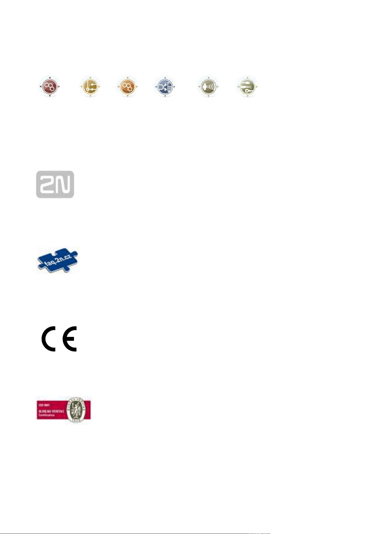
Part No. 916112
2N Access Unit M 13.56 MHz, NFC ready
®
is used for reading RFID cards in the 13.56 MHz bandwidth with the
NFC support. Combining an access reader and a controller, the
device is used for access control inside and outside of buildings.
The following RFID cards can be read:
ISO14443A (Mifare, DESFire)
PicoPass (HID iClass)
Felica
ST SR(IX)
2N Mobile Key
®
Part No. 916112-S
2N Access Unit M secured 13.56 MHz, NFC ready
®
is used for reading secured RFID cards in the 13.56 MHz bandwidth
with the NFC support. Combining an access reader and a controller,
the device is used for access control inside and outside of buildings.
The following RFID cards can be read:
ISO14443A (Mifare, DESFire)
PicoPass (HID iClass)
Felica
ST SR(IX)
2N Mobile Key
®
HID SE (Seos, iClass SE, Mifare SE)

2N TELEKOMUNIKACE a.s., www.2n.cz 8/56
Main Units
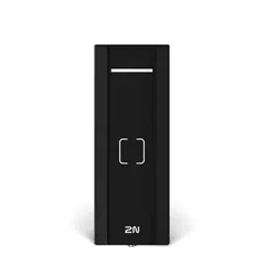
Part No. 916114
2N Access Unit M RFID 125 kHz, 13.56 MHz, NFC
®
is used for reading RFID cards in the 125 kHz and 13.56 MHz
bandwidths with the NFC support. Combining an access reader and
a controller, the device is used for access control inside and outside
of buildings.
The following RFID cards can be read:
EM4xxx
ISO14443A (Mifare, DESFire)
PicoPass (HID iClass)
Felica
ST SR(IX)
2N Mobile Key
®
Part No. 916114-S
2N Access Unit M RFID 125 kHz, secured 13.56 MHz, NFC
®
is used for reading RFID cards in the 125 kHz bandwidth and
secured cards in the 13.56 MHz bandwidth with the NFC support.
Combining an access reader and a controller, the device is used for
access control inside and outside of buildings.
The following RFID cards can be read:
EM4xxx
ISO14443A (Mifare, DESFire)
PicoPass (HID iClass)
Felica
ST SR(IX)
2N Mobile Key
®
HID SE (Seos, iClass SE, Mifare SE)

2N TELEKOMUNIKACE a.s., www.2n.cz 9/56
Main Units
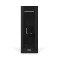
Part No. 916115
2N Access Unit M Bluetooth & RFID 125 kHz, 13.56 MHz, NFC
®
is used for reading RFID cards in the 125 kHz and 13.56 MHz
bandwidths with the NFC support. Combining an access reader, a
Bluetooth module and a controller, the device is used for access
control inside and outside of buildings.
The following RFID cards can be read:
EM4xxx
ISO14443A (Mifare, DESFire)
PicoPass (HID iClass)
Felica
ST SR(IX)
2N Mobile Key
®
Part No. 916115-S
2N Access Unit M Bluetooth & RFID 125 kHz, secured 13.56 MHz,
®
NFC
is used for reading RFID cards in the 125 kHz bandwidth and
secured cards in the 13.56 MHz bandwidth with the NFC support.
Combining an access reader, a Bluetooth module and a controller,
the device is used for access control inside and outside of buildings.
The following RFID cards can be read:
EM4xxx
ISO14443A (Mifare, DESFire)
PicoPass (HID iClass)
Felica
ST SR(IX)
2N Mobile Key
®
HID SE (Seos, iClass SE, Mifare SE)
2N TELEKOMUNIKACE a.s., www.2n.cz 10/56
Main Units
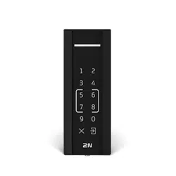
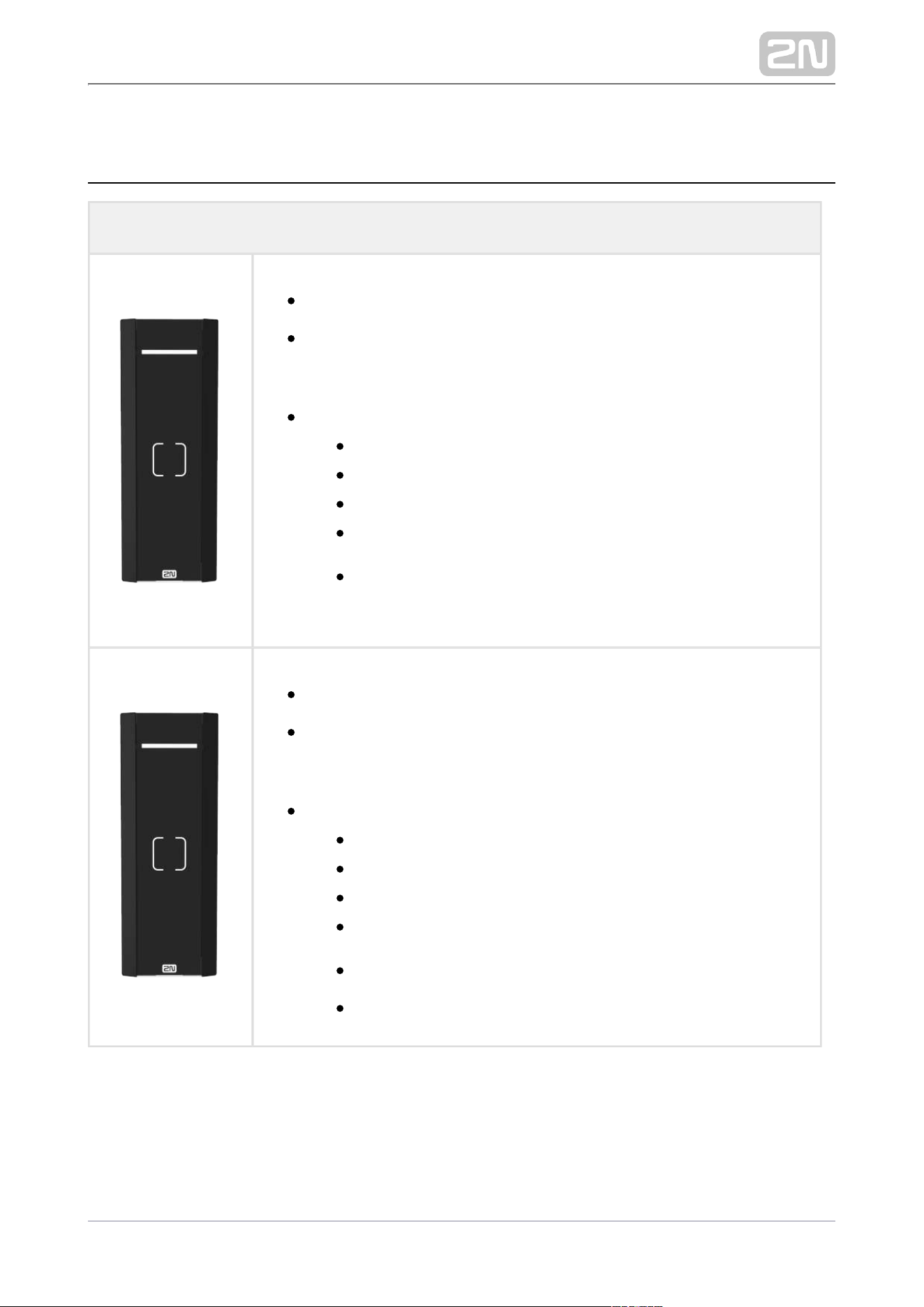
Part No. 916116
2N Access Unit M Touch Keypad & RFID 125 kHz, 13.56 MHz, NFC
®
is used for reading RFID cards in the 125 kHz and 13.56 MHz
bandwidths with the NFC support. Combining an access reader, a
touch keypad and a controller, the device is used for access control
inside and outside of buildings.
The following RFID cards can be read:
EM4xxx
ISO14443A (Mifare, DESFire)
PicoPass (HID iClass)
Felica
ST SR(IX)
2N Mobile Key
®
Part No. 916116-S
2N Access Unit M Touch Keypad & RFID 125 kHz, secured 13.56
®
MHz, NFC
is used for reading RFID cards in the 125 kHz bandwidth and
secured cards in the 13.56 MHz bandwidth with the NFC support.
Combining an access reader, a touch keypad and a controller, the
device is used for access control inside and outside of buildings.
The following RFID cards can be read:
EM4xxx
ISO14443A (Mifare, DESFire)
PicoPass (HID iClass)
Felica
ST SR(IX)
2N Mobile Key
®
HID SE (Seos, iClass SE, Mifare SE)
License
Part No. 916012
2N Access Unit NFC license
2N TELEKOMUNIKACE a.s., www.2n.cz 11/56
License
Part No. 9160401
2N Access Unit Lift module license
Electric Locks
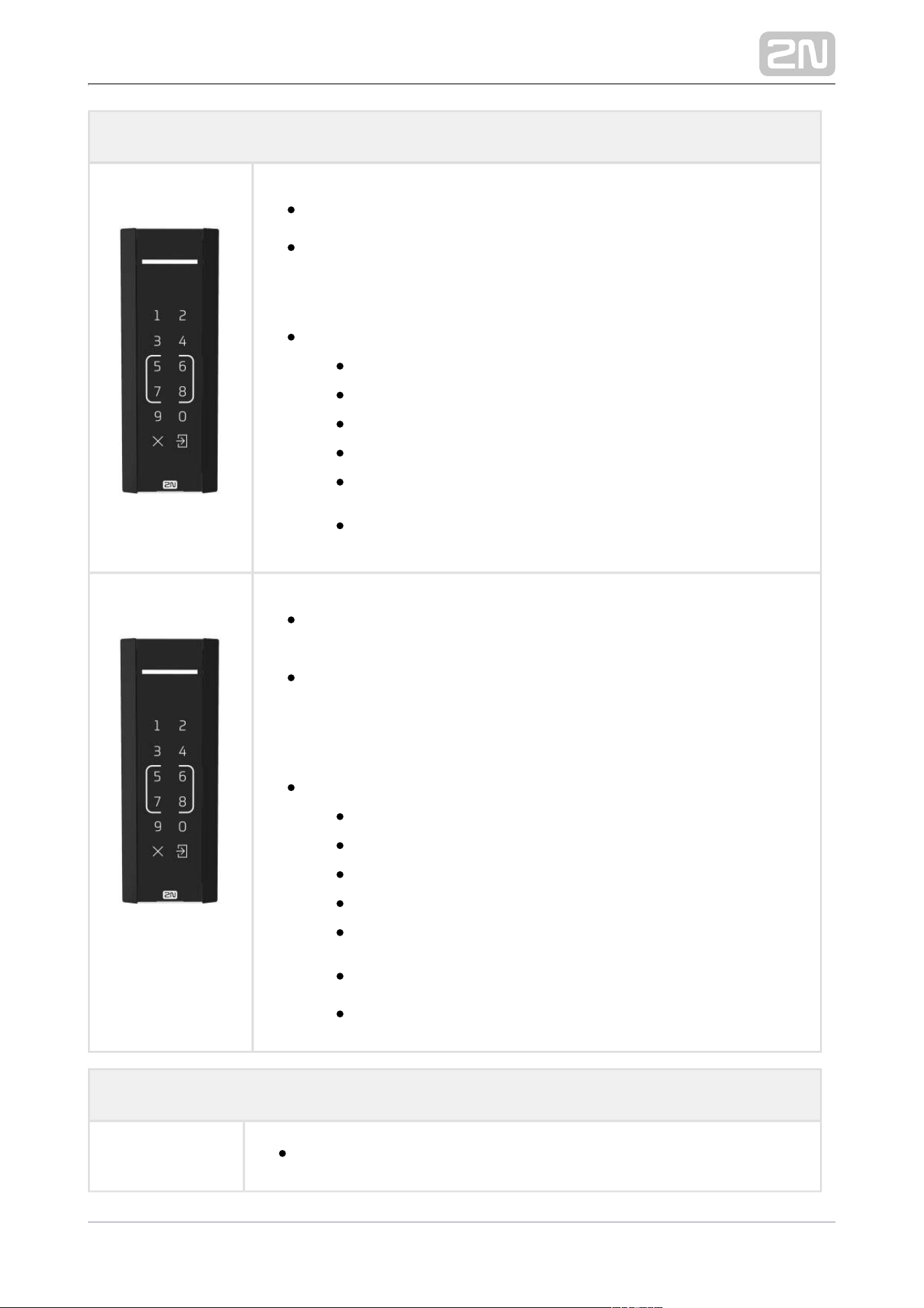
Part No. 932071E
BEFO 11211
12 V / 230 mA DC
low consumption
932081EPart No.
BEFO 11221 with momentum pin
12 V / 230 mA DC
low consumption
A very short electric pulse is enough to put the lock in the
OPEN position and unlock the door. After passage, the lock
gets in the CLOSED (relax) position again.
932091EPart No.
BEFO 11211MB with mechanical blocking
12 V / 230 mA DC
low consumption
You can set the lever mechanically into the OPEN or CLOSED
position. When OPEN, the lock is constantly open, when
CLOSED, it is a standard lock.
2N TELEKOMUNIKACE a.s., www.2n.cz 12/56
Electric Locks
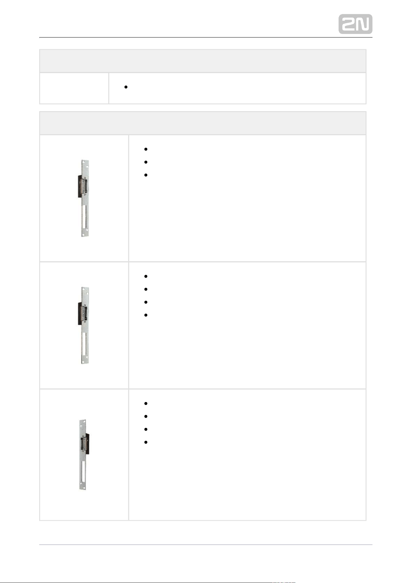
Part No. 932061E
BEFO 11211MB with momentary pin, mechanical blocking
low consumption
12 V / 230 mA DC
A regular lock with a built-in contact to indicate whether the
door is open or closed.
Part No. 932072E
BEFO 31211
fail safe
12 V / 170 mA DC
The reverse lock is closed when electricity is switched on.
When electricity is interrupted, the lock is opened.
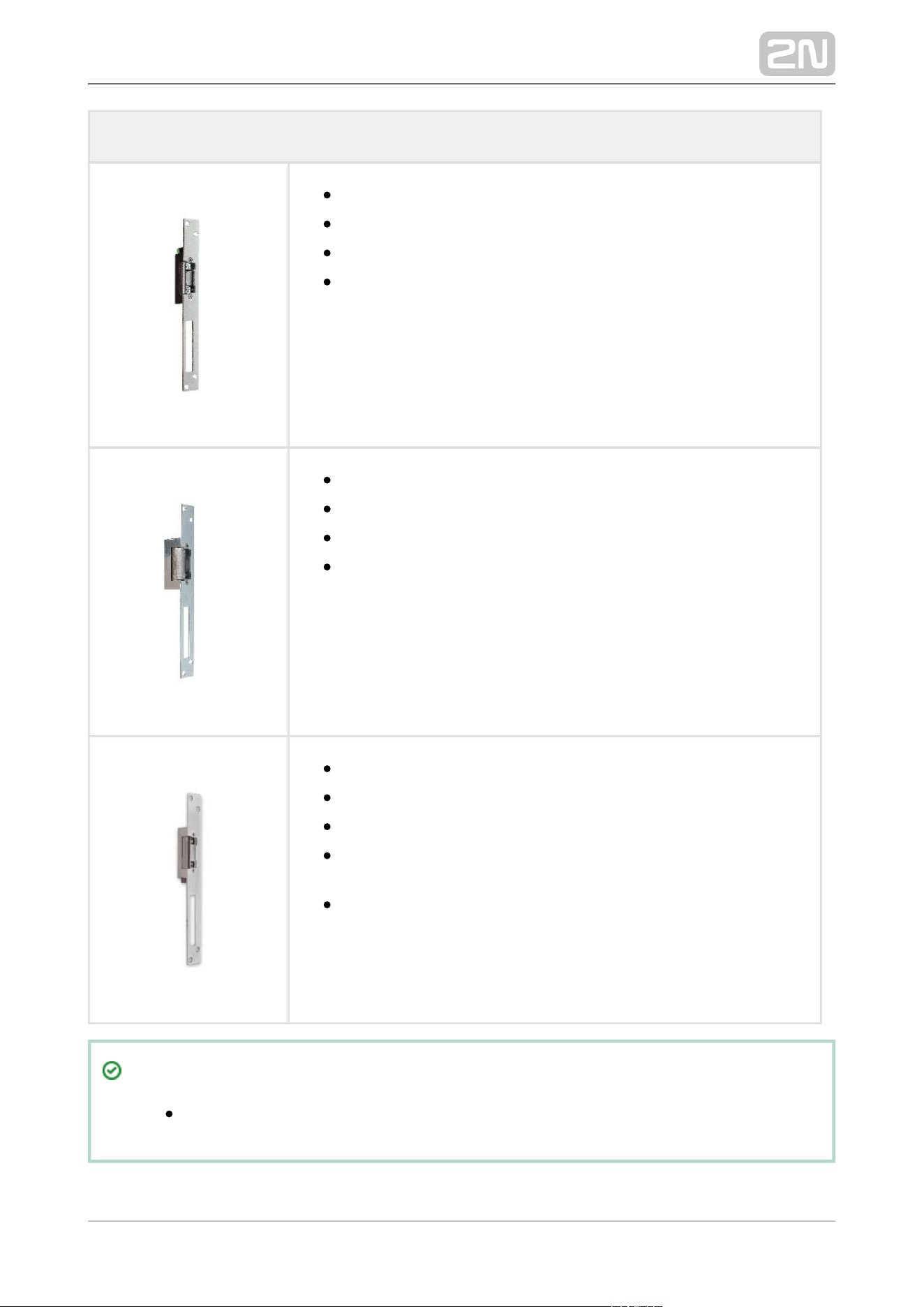
Part No. 932062E
BEFO 321211
fail-safe plus door signaling
12 V / 170 mA
The reverse lock is closed when electricity is switched on.
When electricity is interrupted, the lock is opened.
It contains a built-in contact to indicate whether the door is
open or closed.
Tip
FAQ: Electric locks – Differences between locks for 2N IP access systems
2N TELEKOMUNIKACE a.s., www.2n.cz 13/56
Power Supply
Part Numbers
91378100
91378100E
91378100US
PoE injector – without cable
PoE injector – with EU cable
PoE injector – with US cable
For intercom supply via Ethernet cable where the PoE switch is
absent.
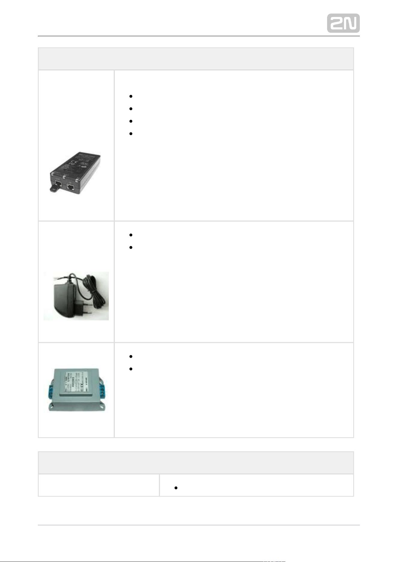
Part Nos.
91341482E
91341482US
12 V / 1 A adapter
A stabilized power supply needs to be used where no PoE is
available.
932928Part No.
12 V transformer
for electric lock
Additional Modules
9159010Part No.
Security Relay
2N TELEKOMUNIKACE a.s., www.2n.cz 14/56
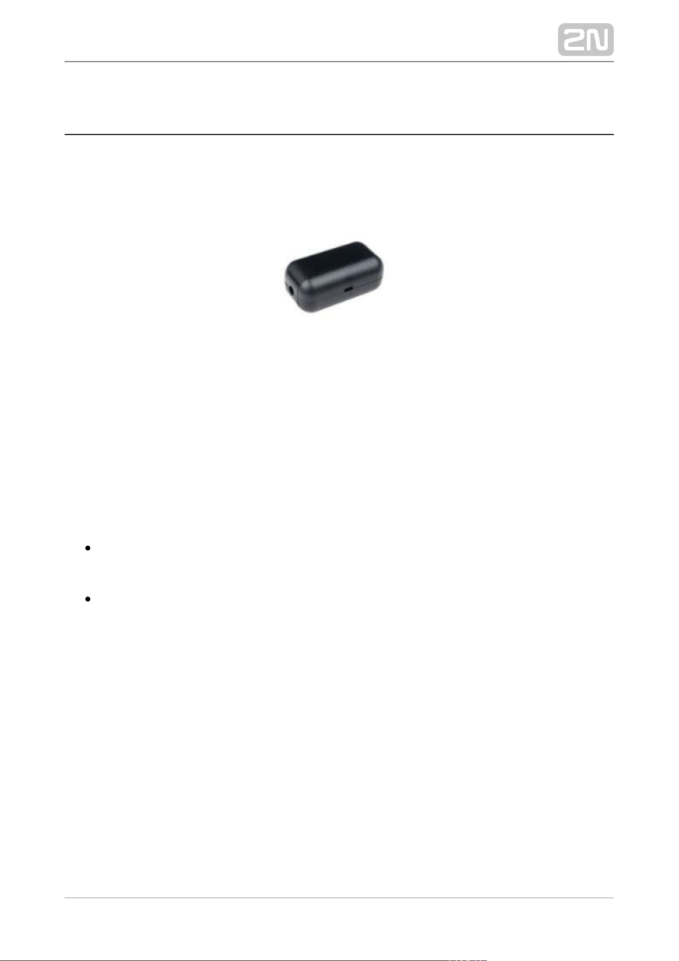
Additional Modules
A handy add-on that significantly enhances door
entry security Prevents lock tampering. Installed
between the intercom, from which it is also
supplied, and the lock to be controlled.
Part No. 9159013
Departure button
Connects the logic input for door unlocking from
inside the building.
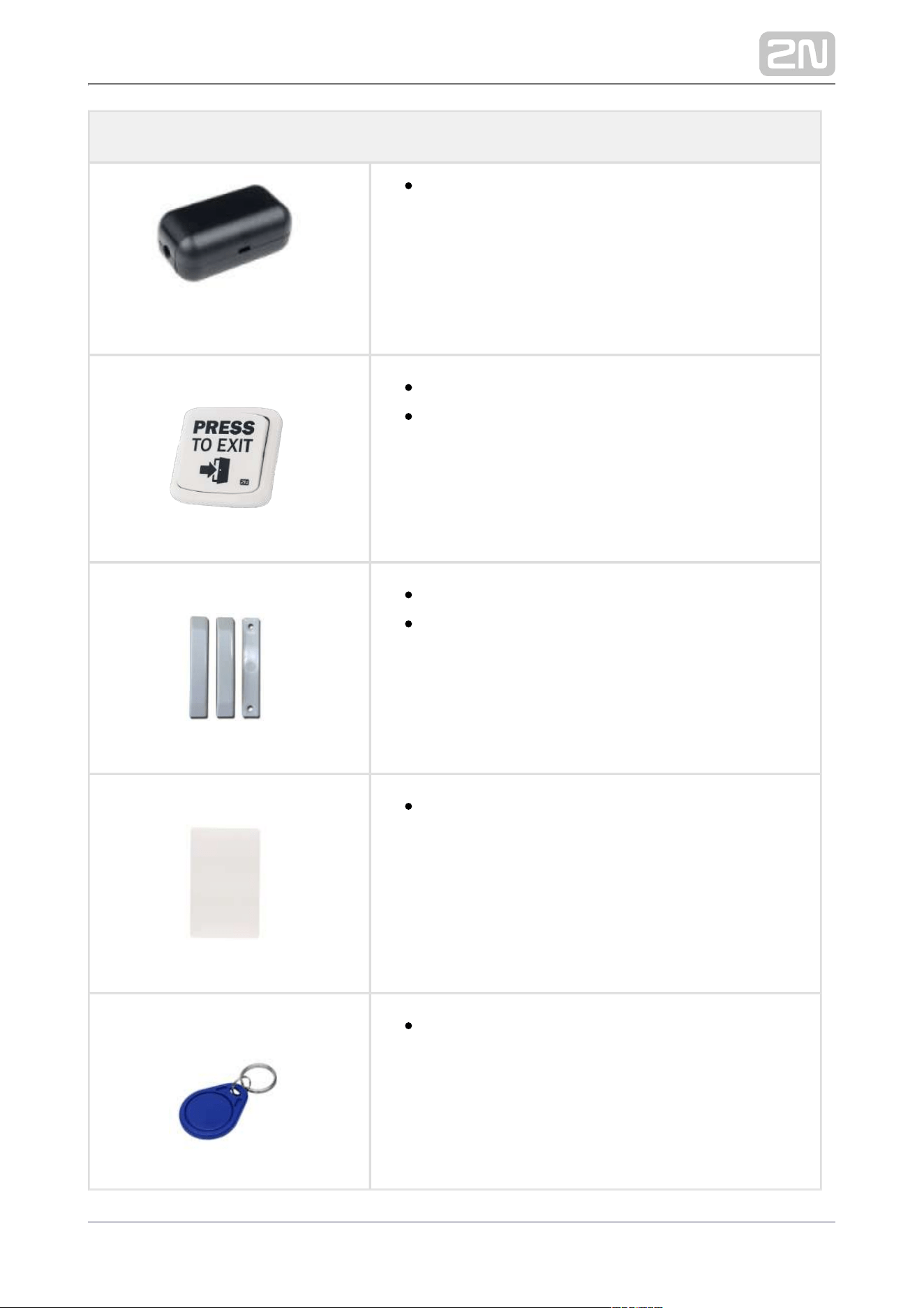
Part No. 9159012
Magnetic door contact
Set for installation on a door, enabling the status of
door opening to be ascertained. Used when the
intercom is used for door protection, to detect
when the door is not closed or forced open.
9134173 Part No.
RFID card, Mifare Classic 1k, 13.56 MHz
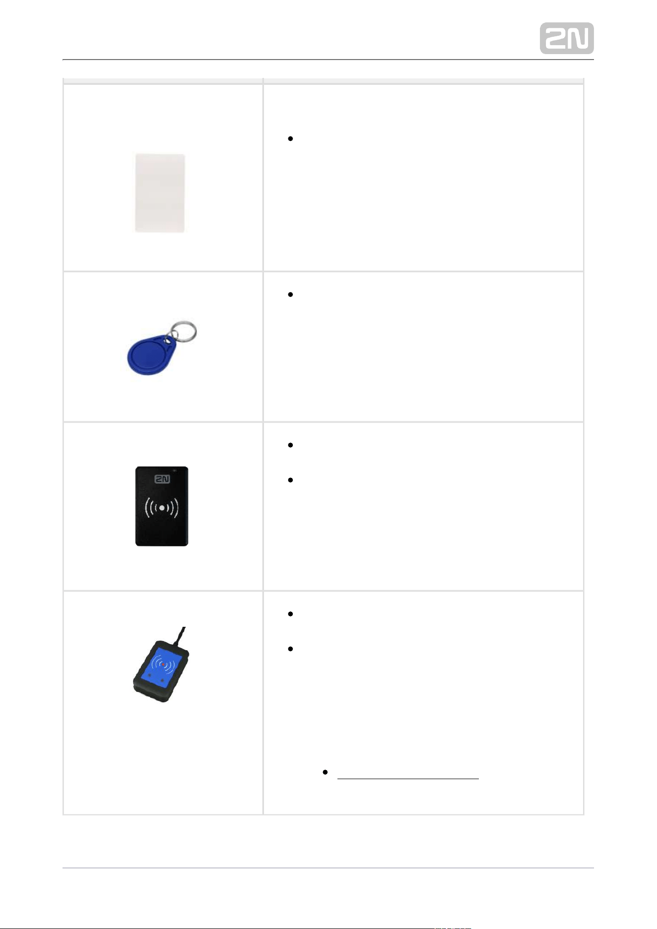
Part No. 9134174
RFID fob, Mifare Classic 1k, 13.56 MHz
2N TELEKOMUNIKACE a.s., www.2n.cz 15/56
9134165EPart No.
RFID card, type EM4100, 125 kHz
9134166EPart No.
RFID fob, type EM4100, 125 kHz
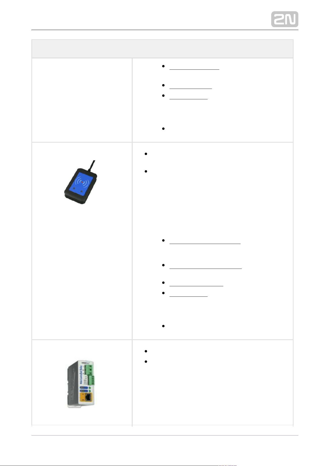
9137420EPart No.
External RFID card reader connectable to a PC via a
USB interface.
Suitable for system administration and adding of
EM41xx cards (125 kHz) via a web interface or 2N
®
Access Commander .
Part No. 9137421E
USB Reader of 13.56 MHz, 125 kHz RFID Cards and
NFC/HCE devices
External RFID card reader connectable to a PC via a
USB interface. Suitable for system administration
and adding 13.56 MHz, 125 kHz cards and Android
platform devices supporting NFC/HCE using 2N IP
web interface or intercom 2N Access Commander
®
. It reads the same types of cards and devices as
card readers in .2N IP intercoms
13.56 MHz/ISO/IEC 14443A Mifare Classic 1k
& 4k, DESFire EV1, Mini, Plus S&X, Ultralight,
Ultralight C
2N TELEKOMUNIKACE a.s., www.2n.cz 16/56
Additional Modules
13.56 MHz/ISO/IEC 14443B CEPAS, HID
iCLASS (CSN only)
13.56/JIS X 6319 Felica
ISO/IEC 18092 SmartPhone with NFC/HCE
support, Android version 6.0 Marshmallow
and higher ( required)2N Mobile Key
®
EMarine
Part No. 9137424E
Secured USB Reader of 13.56 MHz, 125 kHz RFID
Cards and NFC/HCE devices
External secured RFID card reader connectable to a
PC via a USB interface. Suitable for system
administration and adding 13.56 MHz, 125 kHz cards
and Android platform devices supporting NFC/HCE
using the web interface or 2N IP intercom 2N
®
. It reads the same types of Access Commander
cards and devices as card readers in2N IP intercoms
.
13.56 MHz/ISO/IEC 14443A Mifare Classic 1k
& 4k, DESFire EV1, Mini, Plus S&X, Ultralight,
Ultralight C
13.56 MHz/ISO/IEC 14443B CEPAS, HID
iCLASS (CSN or PAC ID)
13.56MHz/JIS X 6319 Felica
ISO/IEC 18092 SmartPhone with NFC/HCE
support, Android version 6.0 Marshmallow
and higher ( required)2N Mobile Key
®
EMarine
Part No. 9137410E
External IP relay – 1 output
A stand-alone IP device, which can be controlled
HTTP from an IP intercom via commands, which can
thus control devices on unlimited distance.
2N TELEKOMUNIKACE a.s., www.2n.cz 17/56
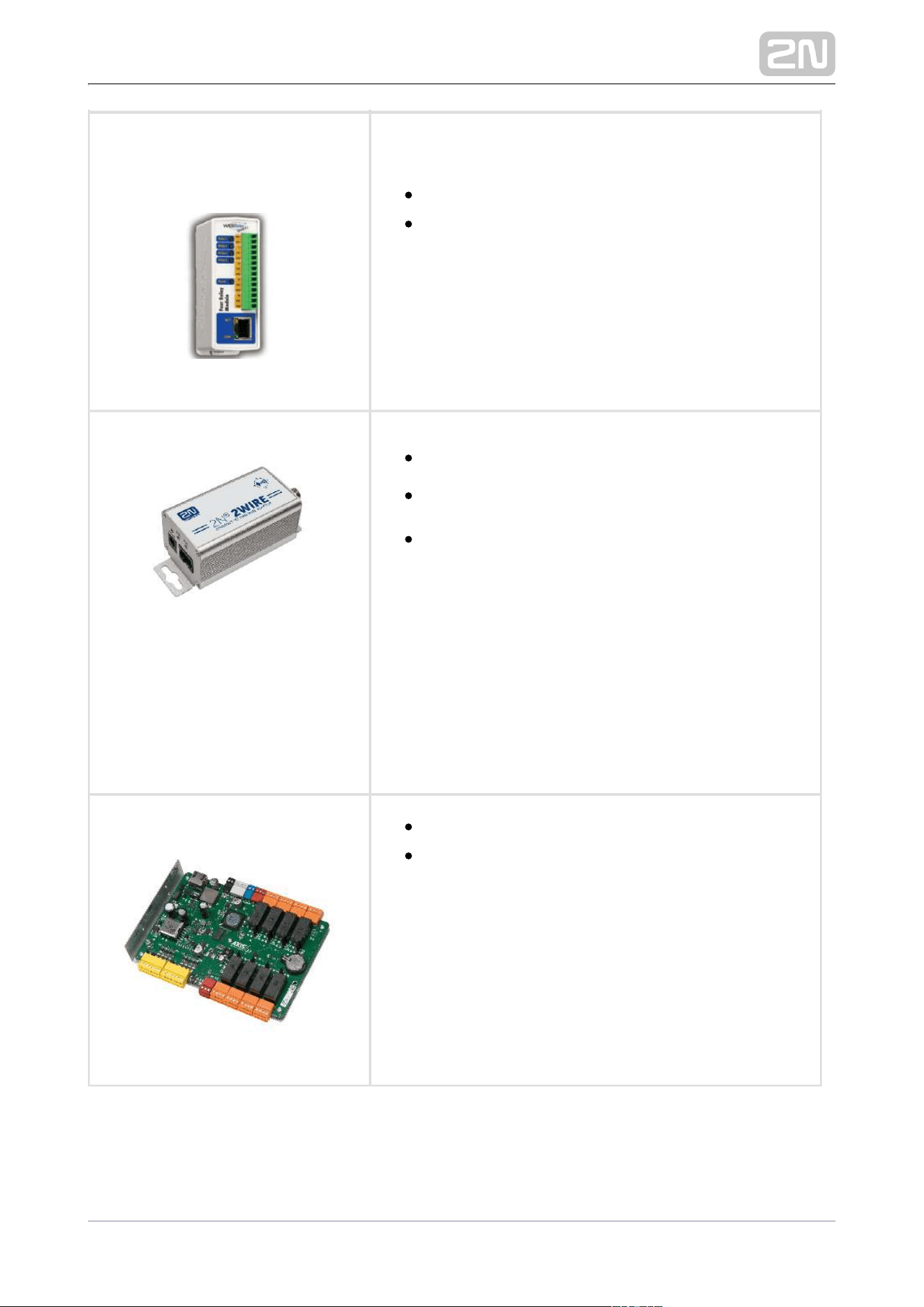
9137411EPart No.
External IP relay – 4 outputs, PoE
A stand-alone IP device, which can be controlled
HTTP from an IP intercom via commands, which can
thus control devices on unlimited distance.
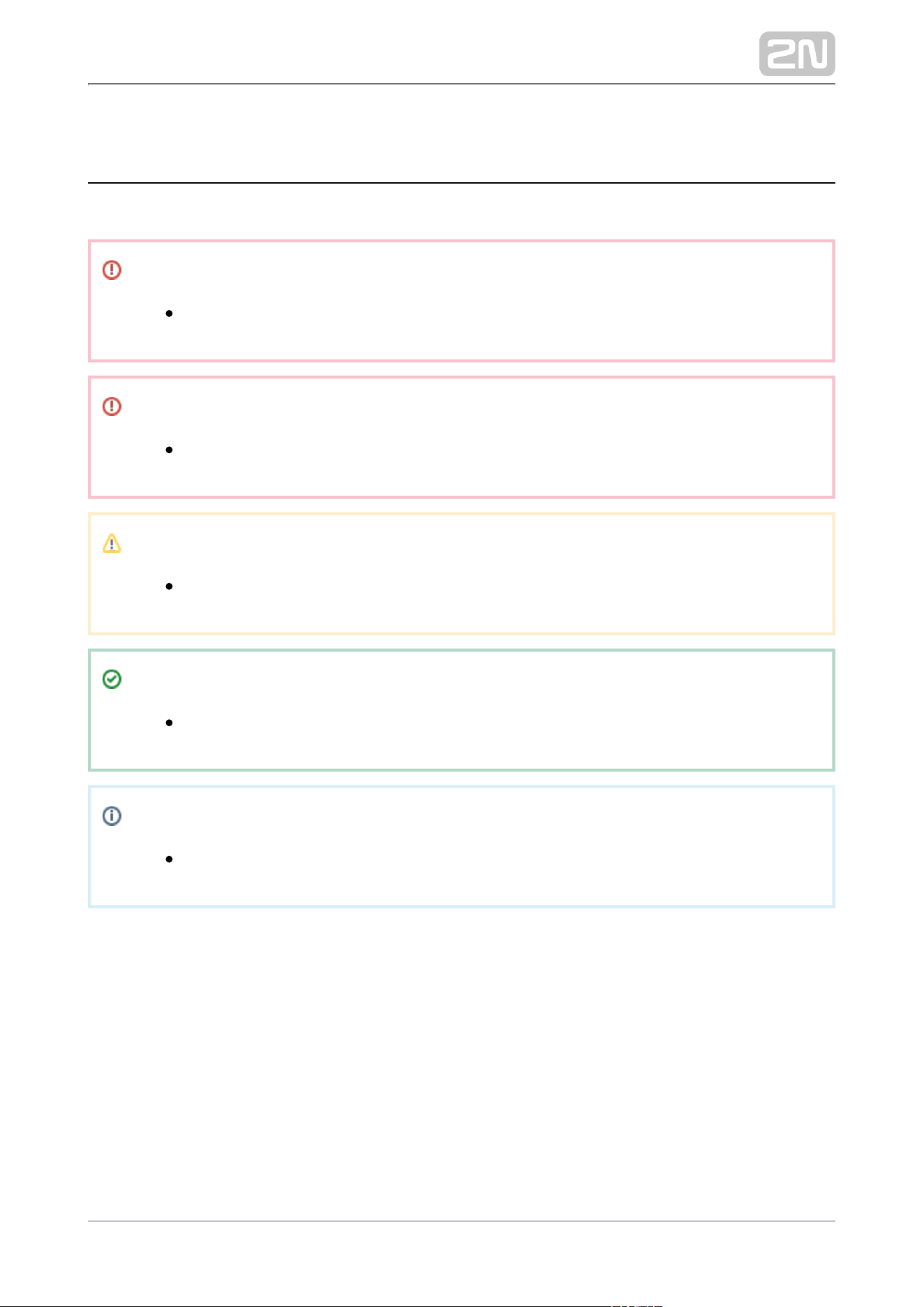
Part No. 9159014EU/US/UK
2Wire2N
®
(set of 2 adapters plus EU/US/UK power supply)
The converter allows you to use the 2N
®
2Wire
existing 2-wire cabling from your original door bell
or door intercom to connect any IP device. You do
not have to configure anything, all you need is one
unit at each end of the cable and a 2N
®
2Wire
power supply connected to at least one of these
units. then provides power not only 2N
®
2Wire PoE
to the second converter, but also to all the other IP
end devices connected.
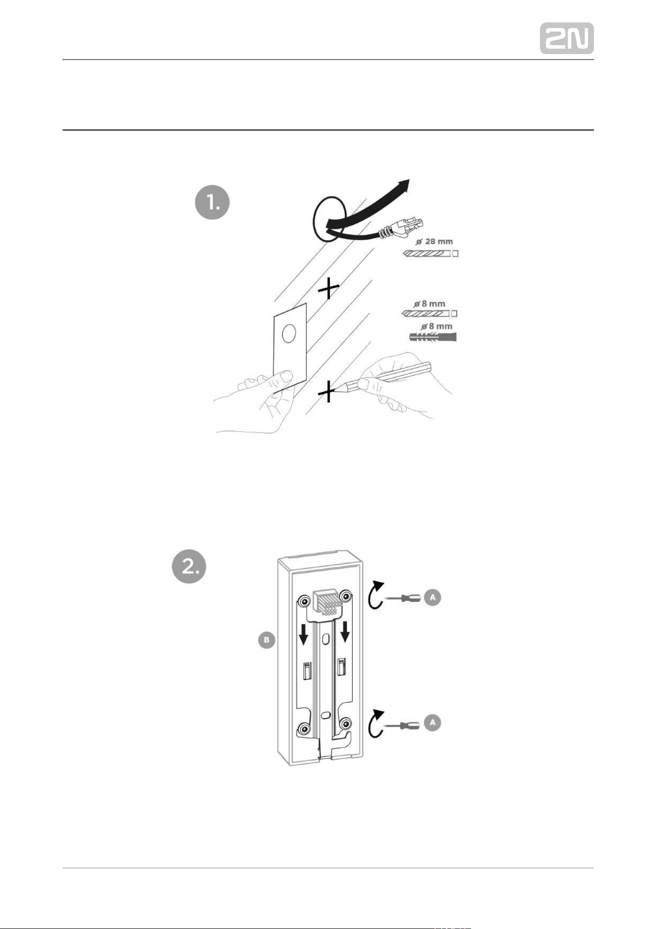
Part No. 9160501
AXIS A9188 Network I/O relay module
Lift control relay module for up to 8 floors

2N TELEKOMUNIKACE a.s., www.2n.cz 18/56
Tip
Refer to the local 2N distributor for more accessories and
recommendations please.
2N TELEKOMUNIKACE a.s., www.2n.cz 19/56
1.2 Terms and Symbols
The following symbols and pictograms are used in the manual:
Safety
Always abide by this information to prevent persons from injury.
Warning
Always abide by this information to prevent damage to the device.
Caution
Important information for system functionality.
Tip
Useful information for quick and efficient functionality.
Note
Routines or advice for efficient use of the device.


2N TELEKOMUNIKACE a.s., www.2n.cz 21/56
2.1 Before You Start
Before starting the installation, please check whether your package 2N Access Unit M
complies with the following list.
Package complies with the following list.
1x 2N Access Unit M
1x Wall holder (screwed to the device)
2x 8 mm dowel
2x Screw with a washer
1x Screw for fitting the device in the holder
1x Torx key (10/20 size)
1x Certificate of ownership
1x Brief Manual
2N TELEKOMUNIKACE a.s., www.2n.cz 22/56
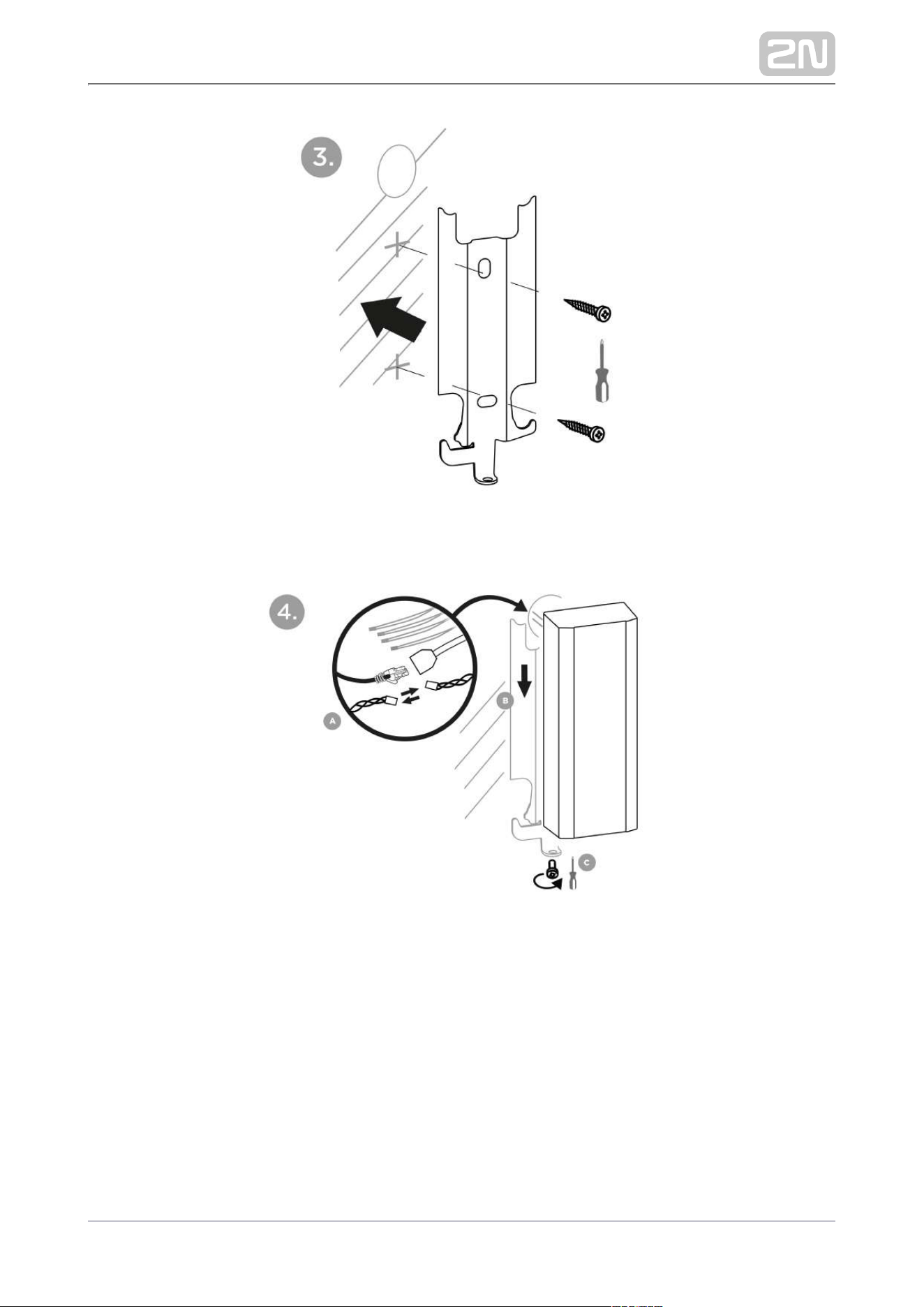
2.2 Mechanical Installation
2N Access Unit M is designed for surface mounting (wall, plasterboard, door frames).
Use the drilling template shown on the device box to prepare holes of the required
sizes for cabling and dowels on the selected place in the required height. Feed the
cables out of the pre-predrilled hole.
Loosen the screws to unscrew the holder from the device backside and slide the
holder downwards.
2N TELEKOMUNIKACE a.s., www.2n.cz 23/56
Then fit the holder through the dedicated holes using the screws enclosed.
Interconnect the fed-out cables with the cabling. Put the device 2N Access Unit M
carefully on the installed holder from above downwards and fix its position on the
holder carrying elements by tightening the screw from the bottom through the holder
hole.

2N TELEKOMUNIKACE a.s., www.2n.cz 24/56
2.3 Electric Installation
2N Access Unit M can be fed either from an external 12 V / 1 A DC power supply or
from a PoE 802.3af supporting LAN.
External power supply
Use a 12 V ± 15 % SELV supply dimensioned to the current consumption required for
the access unit power output to make your device work reliably.
Current consumption
[A]
Available power output
[W]
1 12
PoE Supply
2N Access Unit M is compatible with the PoE 802.3af (Class 0–12.95 W) technology
and can be supplied directly from the LAN via compatible network elements. If your
LAN does not support this technology, insert a PoE injector, Part No. 91378100,
between and the nearest network element. This power supply 2N Access Unit M
p r o v i d e s
with 12 W for its own feeding.2N Access Unit M
Combined power supply
2N Access Unit can be fed from an external power supply and PoE at the same time.
In this configuration, the maximum supply power is available.
Tip
The external power supply can also be used a PoE switch failure backup
making the unit constantly functional.
Connection to LAN
2N Access Unit M is connected to the LAN using a UTP/STP cable (category Cat-5e or
higher) via the dedicated LAN connector. As the device is equipped with the Auto-
MDIX function, you can use both the straight and crossed cable version.

2N TELEKOMUNIKACE a.s., www.2n.cz 25/56
Caution
We recommend the use of a LAN surge protection.
We recommend the use of a shielded SSTP Ethernet cable.

2N TELEKOMUNIKACE a.s., www.2n.cz 26/56
Status Power Consumption
[W]
916112 916112-
S
916114 916114-
S
916115 916115-
S
916116 916116-S
At relax 1.6 W 1.8 W 1.5 W 1.7 W 1.5 W 1.7 W 1.5 W 1.7 W
LED – white strip
100 %
0.12
W
0.12
W
0.12 W 0.12 W 0.12 W 0.12 W 0.12 W 0.12 W
LED – green strip
100 %
0.15
W
0.15
W
0.15 W 0.15
W
0.15
W
0.15 W 0.15
W
0.15 W
LED – red strip 100
%
0.20
W
0.20
W
0.20 W 0.20
W
0.20
W
0.20 W 0.20
W
0.20 W
LED – Bluetooth 100
%
– – – – 0.06
W
0.06 W – –
LED – keypad
backlight 100 %
– – – – – – 0.15
W
0.15 W
Standard room
temperature mode
0.14
W
0.14
W
0.14 W 0.14
W
0.14
W
0.14 W 0.14
W
0.14 W
OUT1 at maximum
possible load
6 W 6 W 6 W 6 W 6 W 6 W 6 W 6 W
Audio 0.7 W 0.7 W 0.7 W 0.7 W 0.7 W 0.7 W 0.7 W 0.7 W
2N TELEKOMUNIKACE a.s., www.2n.cz 27/56
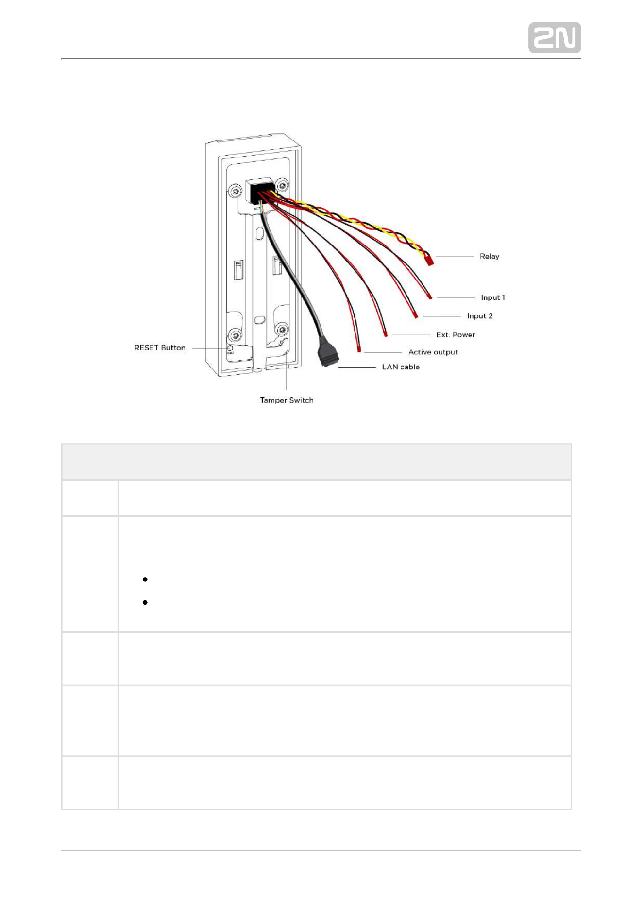
Description of 2N Access Unit M Cabling
Legend
Relay Relay cable with a 30 V / 1 A AC/DC NO/NC contact
Input 1,
2
An input cable used for the connection of a departure button, open door sensor, ESS
etc. in the passive/active mode (−30 V to +30 V DC).
OFF = open contact OR U > 1.5 V
IN
ON = closed contact OR U < 1.5 V
IN
Ext.
Power
For external power supply connection (12 V / 1 A).
Active
output
An active output cable for the connection of or an electric lock: 8 to 12 Security Relay
V DC according to power supply (PoE: 10 V; adapter: power supply voltage minus 2
V), up to 400 mA.
LAN
cable
For LAN connection (PoE 802.3af (Class –13.95 W)).
2N TELEKOMUNIKACE a.s., www.2n.cz 28/56
Legend
Tamper
Switch
A switch that helps detect the removal of a device from the holder installed.
RESET
button
RESET / FACTORY RESET button.
All the available cables are 35 cm long.
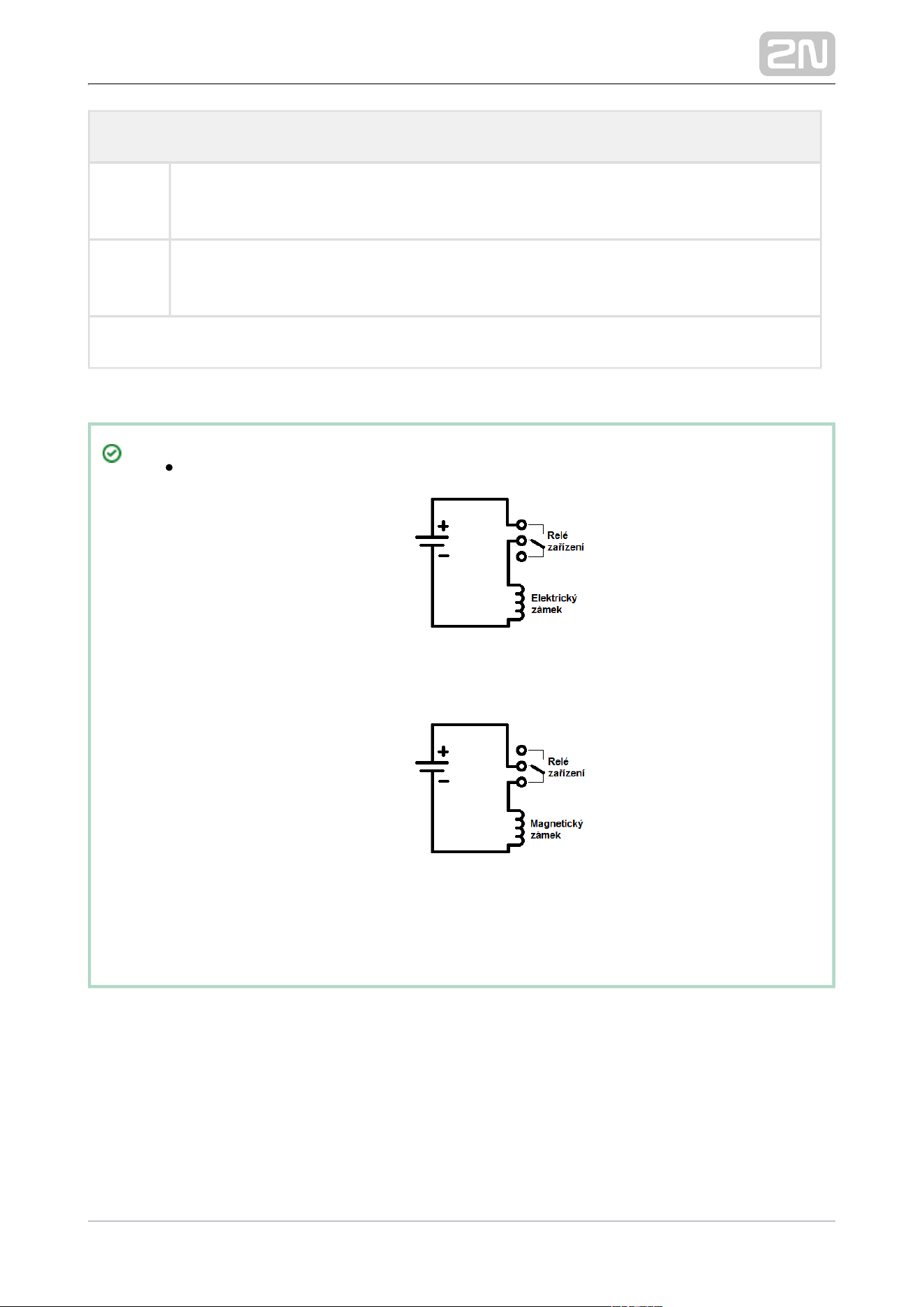
Wiring diagram for Relay cables
The electric lock is unlocked whenever power is supplied
The magnetic lock is unlocked whenever the power supply is
disconnected
2N TELEKOMUNIKACE a.s., www.2n.cz 29/56
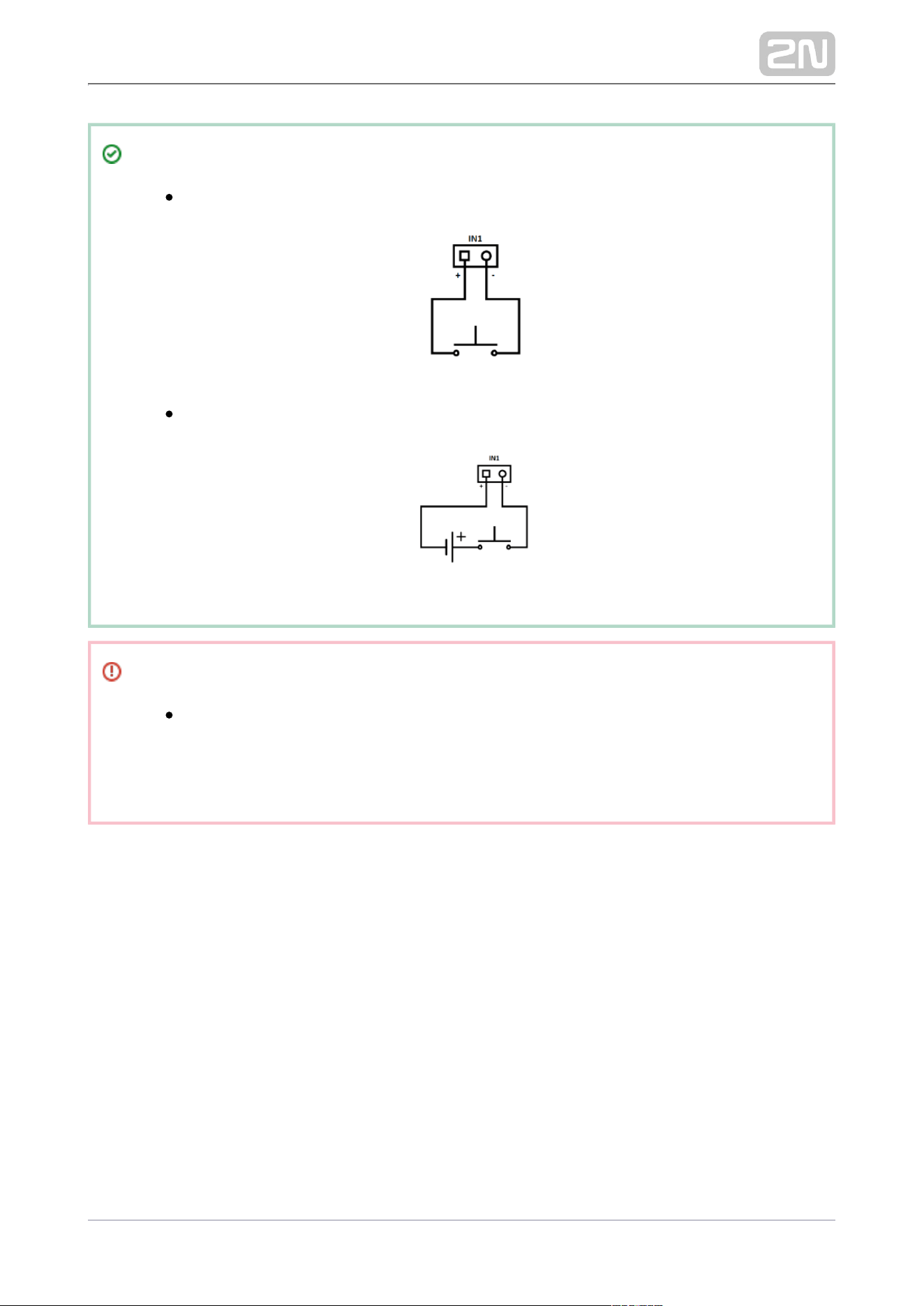
Tip
Wiring Diagram for IN1, IN2 Wires in Active Mode
Wiring Diagram for IN1, IN2 Wires in Passive Mode
Security
The 12 V output is used for lock connection. If, however, the unit (2N IP
Intercom, 2N Access Unit) is installed where unauthorized tampering
may happen (building envelopes), we strongly recommend that Security
(Part No. 9159010) be used for enhanced installation security.Relay
2N TELEKOMUNIKACE a.s., www.2n.cz 30/56
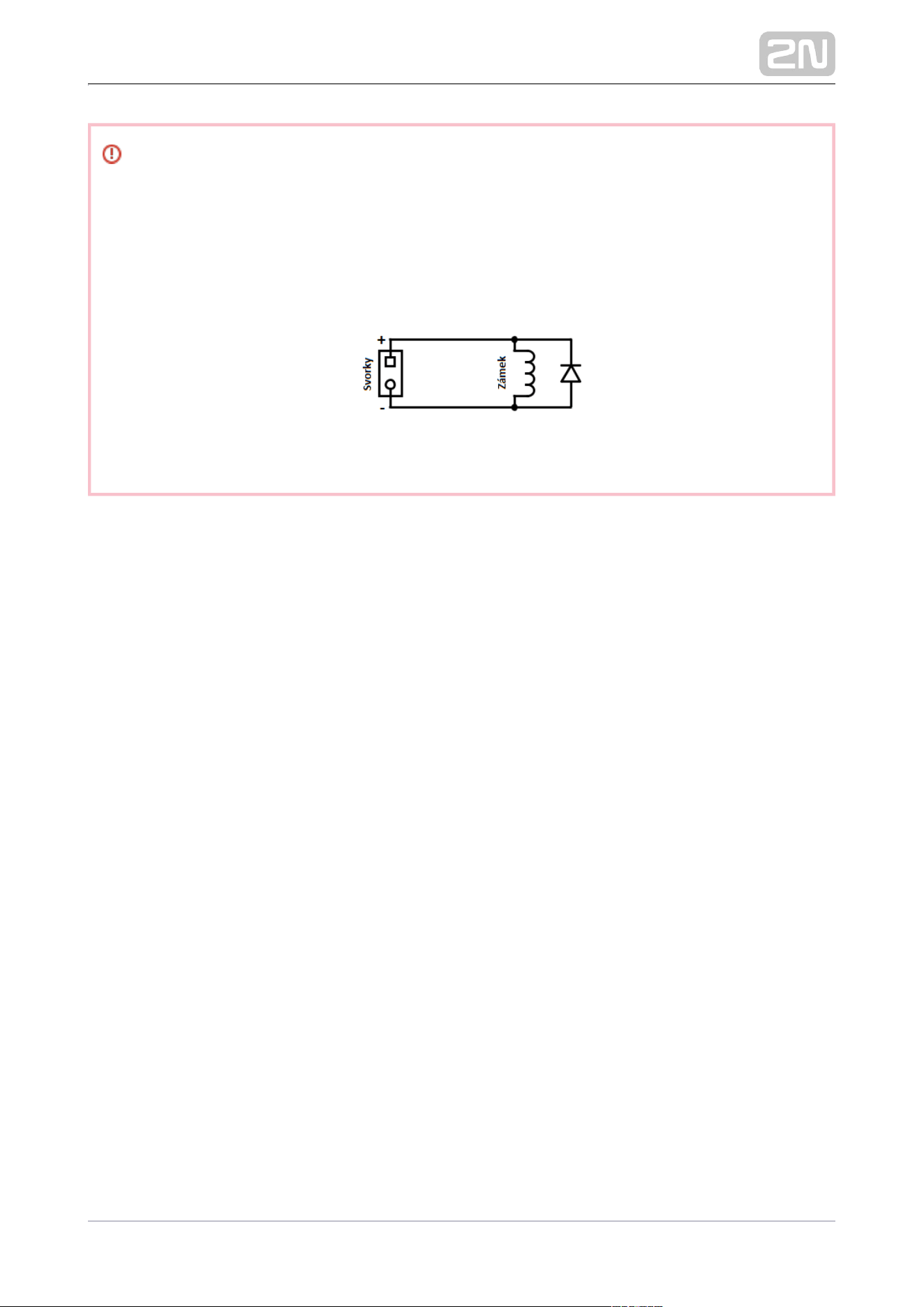
Warning
When you connect a device containing a coil, such as a relay or an
electromagnetic lock, it is necessary to protect the access system output
against voltage peak while switching off the induction load. For this way of
protection we recommend a diode 1 A / 1000 V (e.g., 1N4007, 1N5407,
1N5408) connected antiparallel to the device.
2N TELEKOMUNIKACE a.s., www.2n.cz 31/56
2.4 Extending Module Connection
The ( ) is used for enhancing security between the Security Relay Part No. 9159010
access unit and the connected electric lock. It significantly enhances security of the
connected electric lock as it prevents unlocking by forced opening of 2N Access Unit
.M
Function:
The is a device installed between the access unit (outside the secured Security Relay
area) and an electric lock (inside the secured area). The includes a relay Security Relay
that can only be activated if a valid access card is detected by the unit.
Specifications:
Passive switch: NO and NC contacts, up to 30 V / 1 A AC / DC
Switched output:
Where the security relay is fed from the intercom, 9 to 13 V DC is available on
the output depending on the power supply (PoE: 9 V; adapter: source voltage of
minus 1 V) / 400 mA DC.
Where the security relay is fed from an external power supply, 12 V / 700 mA DC
is available on the output.
Dimensions: (56 x 31 x 24) mm
Weight: 20 g
Installation:
The is installed onto a two-wire cable between the access unit and the Security Relay
electric lock inside the area to be secured (typically behind the door). The device is
powered and controlled via this two-wire cable and thus can be added to an existing
installation. Thanks to its compact dimensions, the device can be installed into a
standard mounting box.
2N TELEKOMUNIKACE a.s., www.2n.cz 32/56
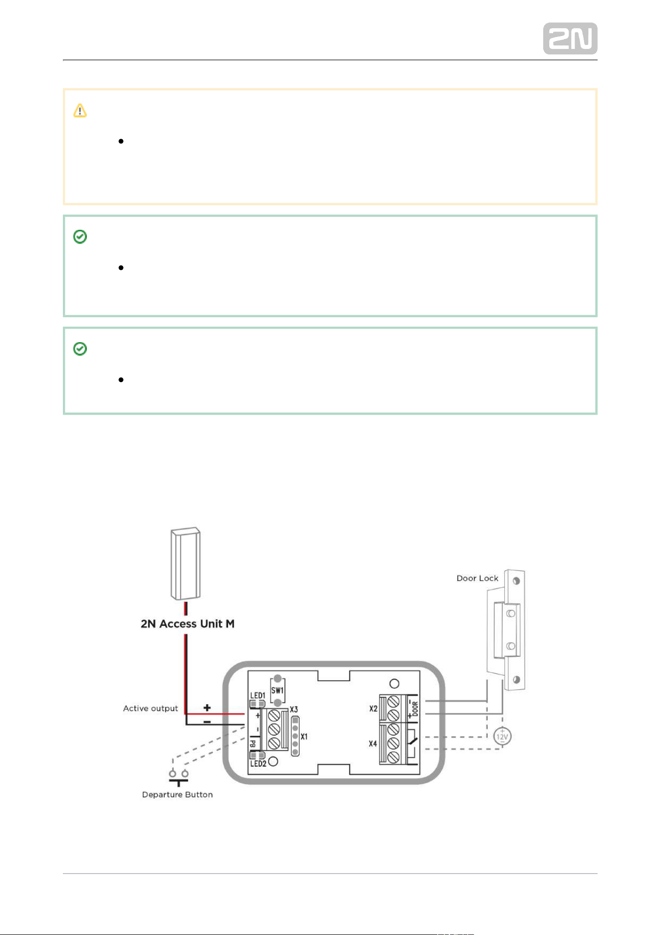
Connection:
Connect the to the access unit as follows:Security Relay
To the Active output
Connect the electric lock to the output as follows:Security Relay
To the switched output.
To the passive output in series with an external power supply.
The device also supports a Departure button connected between the ‘PB’ and – Helios
/2N IP intercom’ terminals. Press the Departure button to activate the output for 5
seconds.
Status Signaling:
Green LED Red LED Status
flashing off Operational mode
on off Activated output
flashing flashing Programming mode – waiting for initialization
on flashing Error – wrong code received
Configuration:
Connect the to the properly set access unit security output. Refer Security Relay
to the . Make sure that one LED at least is 2N Access Unit Configuration Manual
on or flashing.
Press and hold the Reset button for 5 seconds to put the device Security Relay
in the programming mode (both the red and green LEDs are blinking).
Activate the output switch using the keypad, telephone, etc. The first code sent
from the intercom will be stored in the memory and considered valid. After code
initialization, the will pass into the operational mode (the green Security Relay
LED is blinking).
2N TELEKOMUNIKACE a.s., www.2n.cz 33/56
Caution
In case the factory default values are reset on a device with a firmware
version 2.18 or higher, it is necessary to reprogram using Security Relay
the instructions above.
Tip
FAQ: 2N® Security Relay – description of the device and use with the 2N
IP intercoms
Tip
Video Tutorial: 2N IP Door Intercoms – Security Relay
Connection:

2N TELEKOMUNIKACE a.s., www.2n.cz 34/56
3. Detection of 2N Access Unit M
using 2N® Network Scanner
2N Access Unit M is configured via the administration web server. Connect the device
to the LAN IP and make sure it is properly powered.
2N TELEKOMUNIKACE a.s., www.2n.cz 35/56
1.
2.
3.
2N ® Network Scanner Description
The application helps you find the IP addresses of all the devices in 2N Access Unit M
the LAN. Download the app from the 2N web sites ( ). Make sure that www.2n.cz
Microsoft .NET Framework 2.0 is installed for successful app installation.
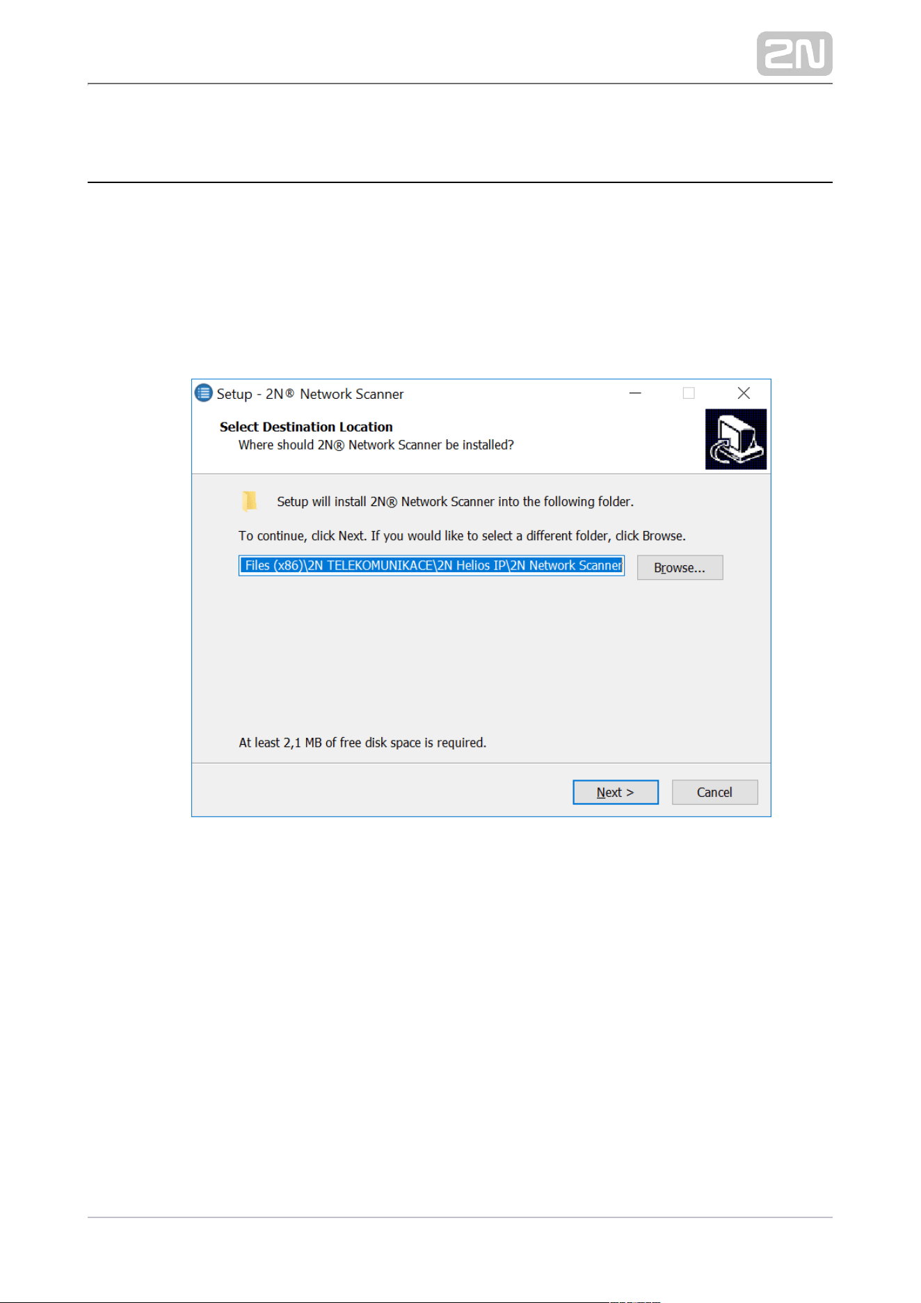
Run the installer.2N
®
Network Scanner
Use the Setup Wizard for successful installation.
Setup Wizard of 2N
®
IP Network Scanner
Having installed , start the application using the 2N
®
IP Network Scanner
Microsoft Windows Start menu.
2N TELEKOMUNIKACE a.s., www.2n.cz 36/56
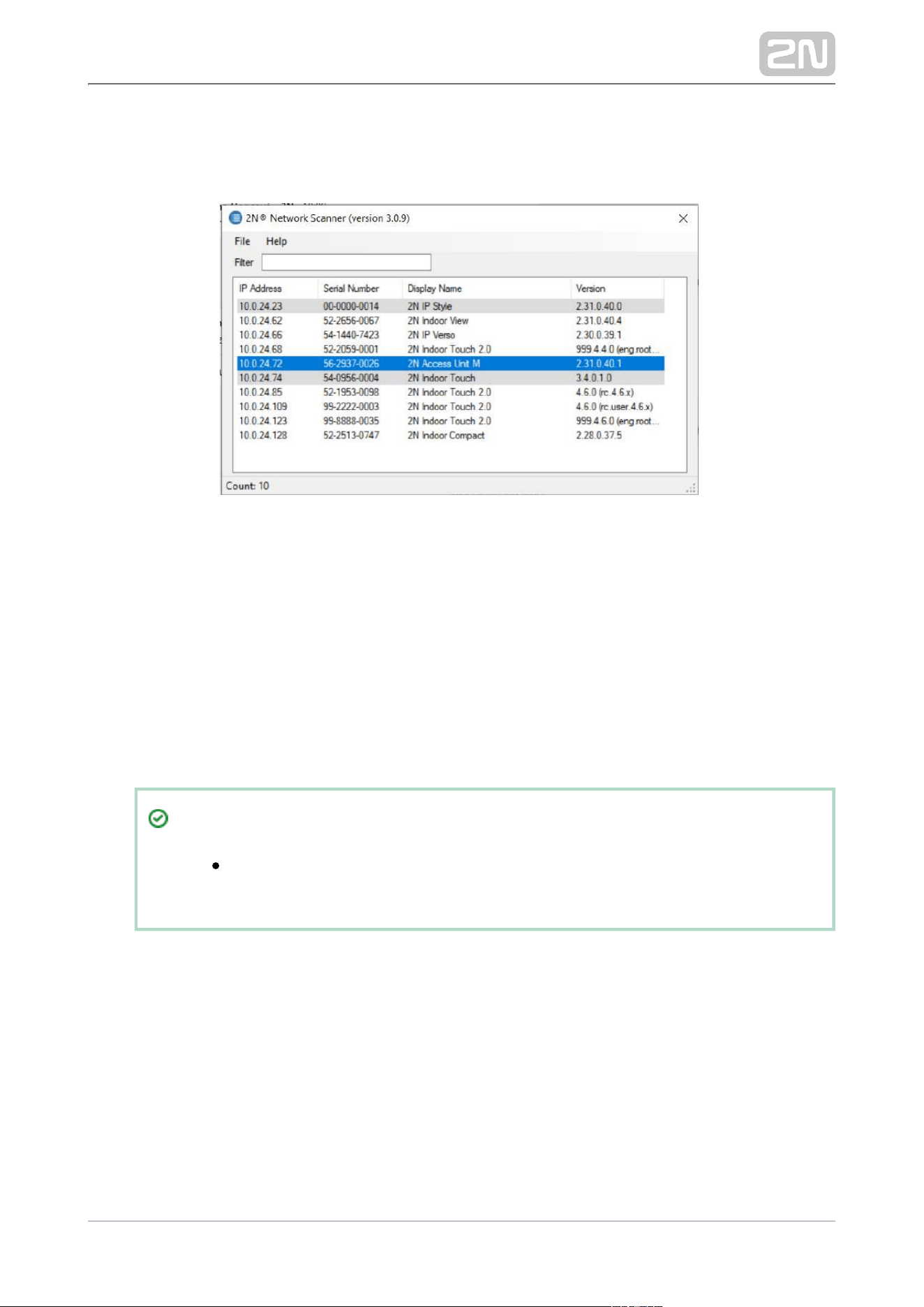
1.
Once started, the application begins to automatically search for all the 2N devices in
the LAN including their smart extensions which are DHCP/statically assigned IP
addresses. All the devices are then displayed in a table
Window of 2N
®
IP Network Scanner
Select the device to be configured and right-click it. Select 2N Access Unit M
to open the administration web interface login
Browse…
2N Access Unit M
window for configuration. To change the device IP address, select and
Config
enter the required static IP address or activate DHCP. The default configuration
password is 2n. If the found device is grey highlighted, its IP address cannot be
configured using this application. In that case, click Refresh to find the device
again and check whether multicast is enabled in your network.
Tip
Double click the selected row in the list to 2N
®
IP Network Scanner
access the device web interface easily.

2N TELEKOMUNIKACE a.s., www.2n.cz 37/56
2N
®
IP Network Scanner IP Address Change
2N TELEKOMUNIKACE a.s., www.2n.cz 38/56
4. Factory Reset
Located in the left-hand bottom corner of device backside, the Reset button helps you
reset the factory default values, restart the device, find the device IP address and
switch the static/dynamic mode. The LED indicators are located on the device
backside.
Press the button shortly (< 1 s) to restart the system without changing configuration.
Note
The time interval between the short press of the 2N Access Unit M
RESET button and reconnection of the device to the network is 26 s.
2N TELEKOMUNIKACE a.s., www.2n.cz 39/56
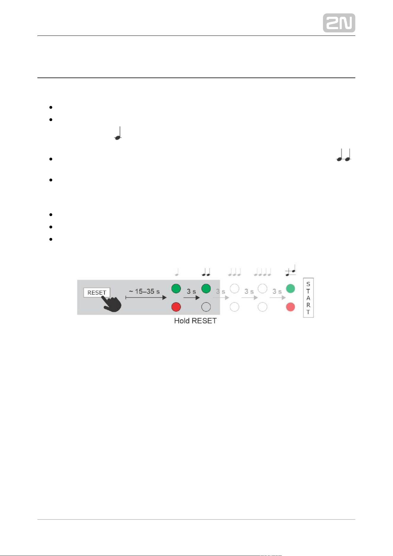
IP Address Finding
Follow the instructions below to :identify the current IP address
Press and hold the RESET button.
Wait until the red and green LEDs go on simultaneously on the device and the
acoustic signal can be heard (approx. 15–35 s).
Release the RESET button.
The device announces the current IP address via the speaker automatically.
Note
The delay between the RESET button press and the first light and sound
signaling is 15–35 s depending on the 2N Access Unit model used.
For the time interval is 14 s.2N Access Unit M
2N TELEKOMUNIKACE a.s., www.2n.cz 40/56
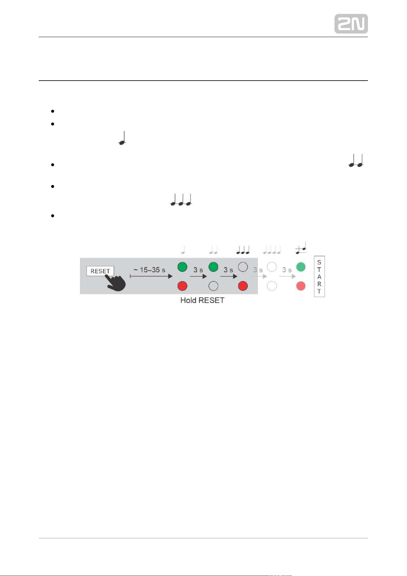
Static IP Address Setting
Follow the instructions below to switch on the (DHCP OFF): Static IP address mode
Press and hold the RESET button.
Wait until the red and green LEDs go on simultaneously on the device and the
acoustic signal can be heard (approx. 15–35 s).
Wait until the red LED goes off and the acoustic signal can be heard
(approx. for another 3 s).
Release the RESET button.
The following network parameters will be set after restart:
IP address: 192.168.1.100
Network mask: 255.255.255.0
Default gateway: 192.168.1.1
2N TELEKOMUNIKACE a.s., www.2n.cz 41/56
Dynamic IP Address Setting
Follow the instructions below to switch on the (DCHP ON):Static IP address mode
Press and hold the RESET button.
Wait until the red and green LEDs go on simultaneously on the device and the
acoustic signal can be heard (approx. 15–35 s).
Wait until the red LED goes off and the acoustic signal can be heard
(approx. for another 3 s).
Wait until the green LED goes off and the red LED goes on again and the
acoustic signal can be heard (approx. for another 3 s).
Release the RESET button.
2N TELEKOMUNIKACE a.s., www.2n.cz 42/56
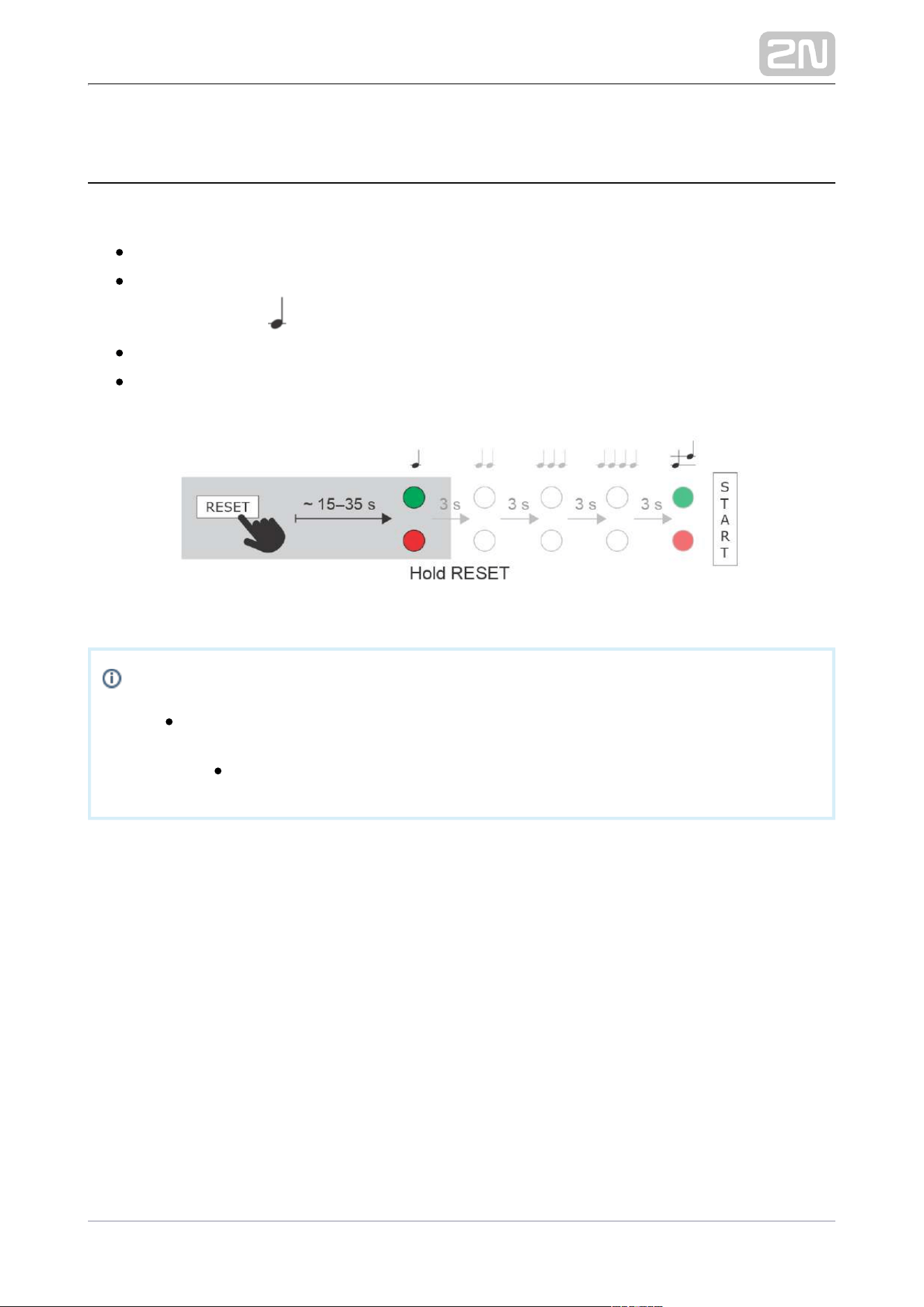
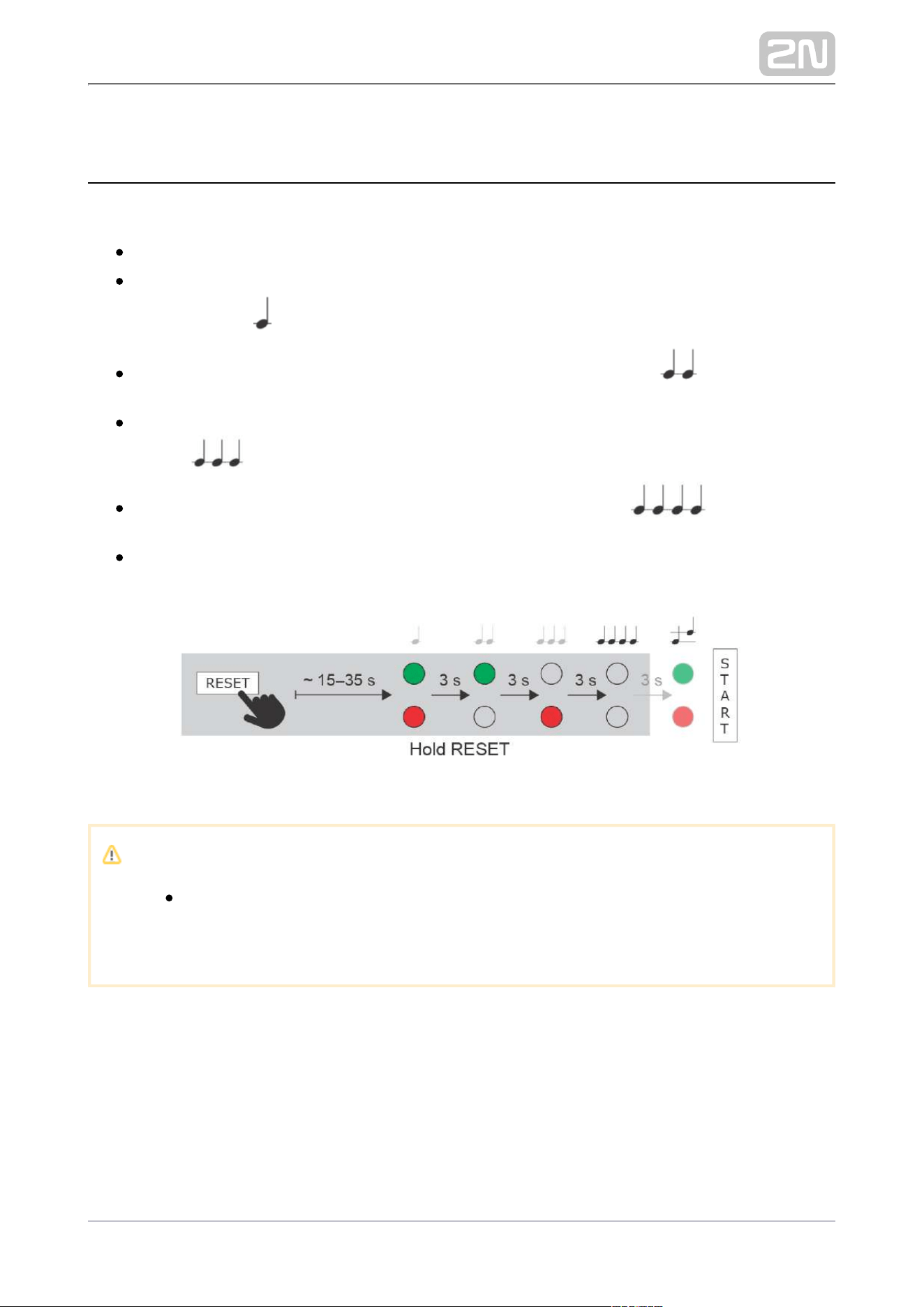
Factory Reset
Follow the instructions below to :reset the factory default values
Press and hold the RESET button.
Wait until the red and green LEDs go on simultaneously and the acoustic signal
(approx. 15–35 s). can be heard
Wait until the red LED goes off and the can be heard acoustic signal
(approx. for another 3 s).
Wait until the green LED goes off and the red LED goes on again and acoustic
can be heard (approx. for another 3 s). signal
Wait until the red LED goes off and the can be heard acoustic signal
(approx. for another 3 s).
Release the RESET button.
Caution
In case the factory default values are reset on the device with a firmware
version 2.18 or higher, it is necessary to reprogram using Security Relay
the instructions from Subsection 2.4 Extending ModuleConnection
2N TELEKOMUNIKACE a.s., www.2n.cz 43/56
5. Maintenance
If used frequently, the device, its keypad in particular, gets unavoidably dirty. Use a
piece of soft cloth moistened with clean water to clean the device. You are
recommended to follow the principles below while cleaning:
Do not use aggressive detergents (such as abrasives or strong disinfectants).
Clean the device in dry weather in order to make waste water evaporate quickly.
Warning
Prevent water from getting inside the access unit.
Do not use alcohol-based cleaners.
2N TELEKOMUNIKACE a.s., www.2n.cz 44/56
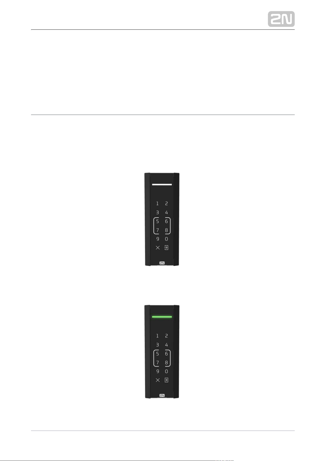
6. Status Signaling
The operational statuses are indicated by a light signal on the 2N Access Unit M
device front side. The light signal can be accompanied with an acoustic signal if set so.
Refer to of the 2N Access Unit Configuration Manual for the setting 5.3.3 Audio
options.
The white LED light indicates the power supply and operation states.
2N TELEKOMUNIKACE a.s., www.2n.cz 45/56
The green LED light goes on whenever a valid PIN code in entered via the keypad or a
valid RFID card is applied. Subsequently, the set switch is activated. A valid
authentication is indicated by an acoustic signal if set so.
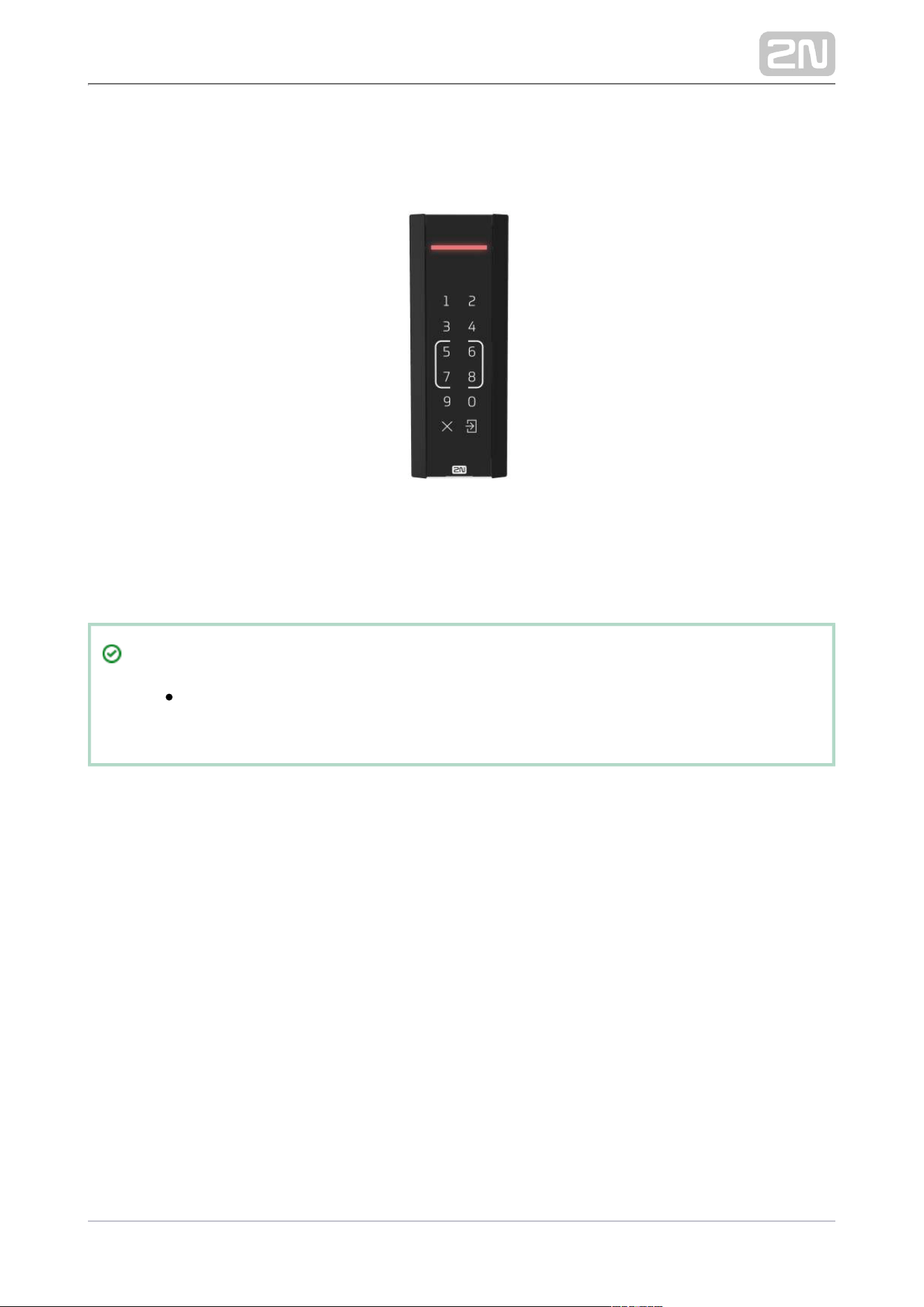
The red LED light goes on whenever an invalid PIN code is entered via the keypad or
an invalid RFID card is applied. Subsequently, the set switch is not activated. An
invalid authentication is indicated by an acoustic signal if set so.
Tip
Set the LED backlight level in the Hardware/Backlight section, refer to
of the Configuration Manual for more details.5.3.4 Backlight

2N TELEKOMUNIKACE a.s., www.2n.cz 46/56
7. Technical Parameters
Audio
1 W / 8 ΩLoudspeaker:
Power Supply
12 V ±15 % / 1 A
PoE 802.3af (Class 0–12.95 W)
Interface
10/100BASE-TX with Auto-MDIX, RJ-45 female (pigtail)LAN:
Cat-5e or higherRecommended cabling:
DHCP opt. 66, SMTP, 802.1x, TFTP, HTTP, HTTPS, SyslogSupported protocols:
NO/NC contact, up to 30 V / 1 A AC/DCPassive switch:
8 to 12 V DC according to power supply (PoE: 10 V; Active switch output:
adapter: supply voltage minus 2 V), up to 400 mA
part of Tamper switch: 2N Access Unit M
Inputs (Input 1,2): passive/active mode (−30 V to +30 V DC)
OFF = open or U > 1.5 V
in
ON = short-circuited or U < 1.5 V
in
RFID card reader
Frequency: 13.56 MHz & 125 kHz
Supported 13.56 MHz cards (card serial number is only read):
ISO14443A (Mifare, DESFire)
PicoPass (HID iClass)
FeliCa
ST SR(IX)
2N Mobile Key
®
HID SE ((Seos, iClass SE, Mifare SE) for secured cards only)

2N TELEKOMUNIKACE a.s., www.2n.cz 47/56
HID SE ((Seos, iClass SE, Mifare SE) for secured cards only)
Supported 125 kHz cards: EM41xx
Bluetooth
Bluetooth 5.0 in compliance with BLE (Bluetooth Low Energy)
RX sensitivity: up to −94.8 dBm per 1Mbps
Support of higher applications: Android 6.0 Marshmallow and higher, iOS 12.0
and higher
Mechanical properties
Cover: robust ASA/PC construction material, which is also used for such car
parts as lateral mirrors, radiator masks, etc. + chemically hardened 3 mm thick
glass
Operating temperature: −40 °C to 60 °C
Working relative humidity: 10 % – 95 % (non-condensing)
Maximum altitude for intended use: 2000 m a.s.l.
Storage temperature: −40 °C to 70 °C
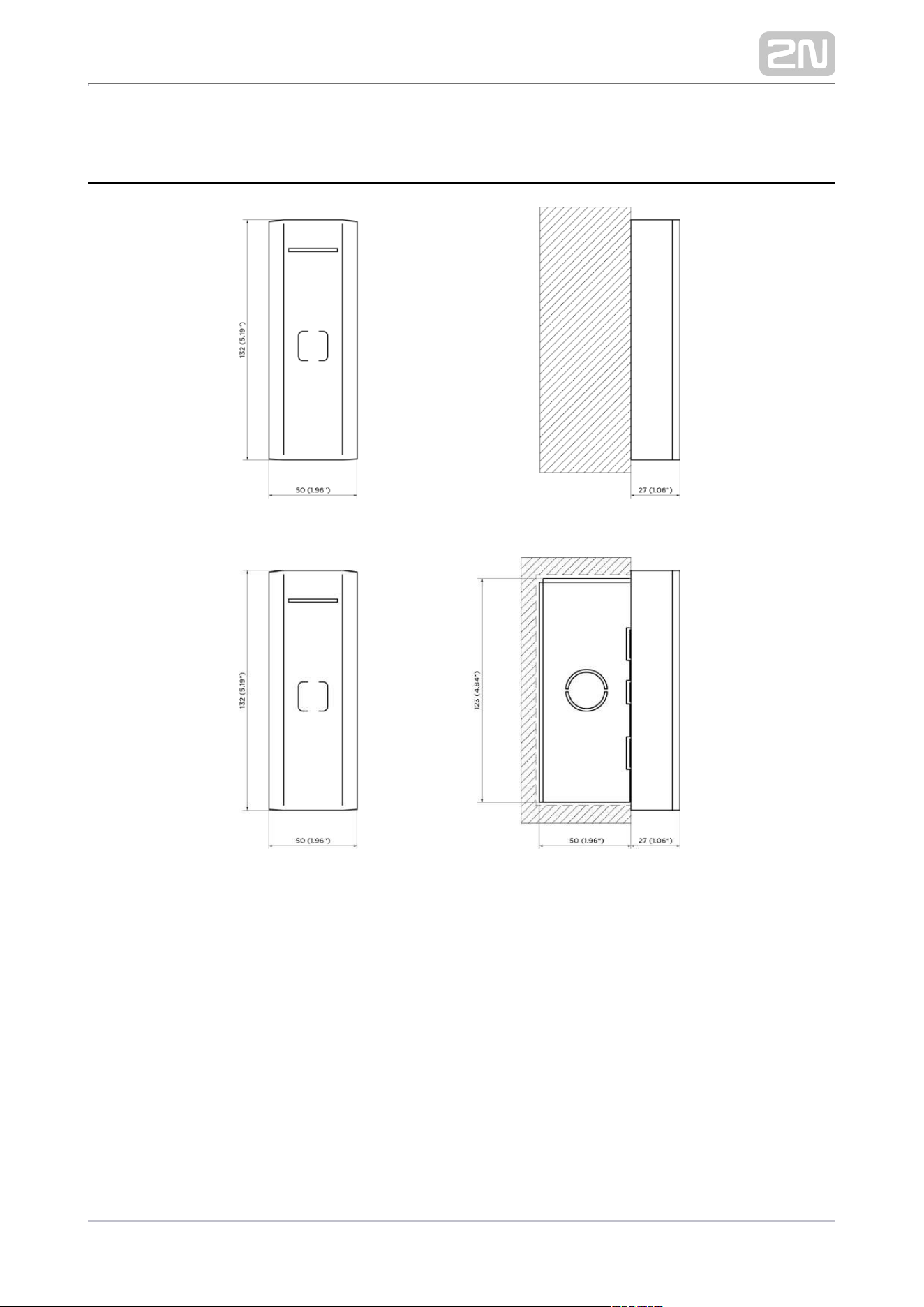
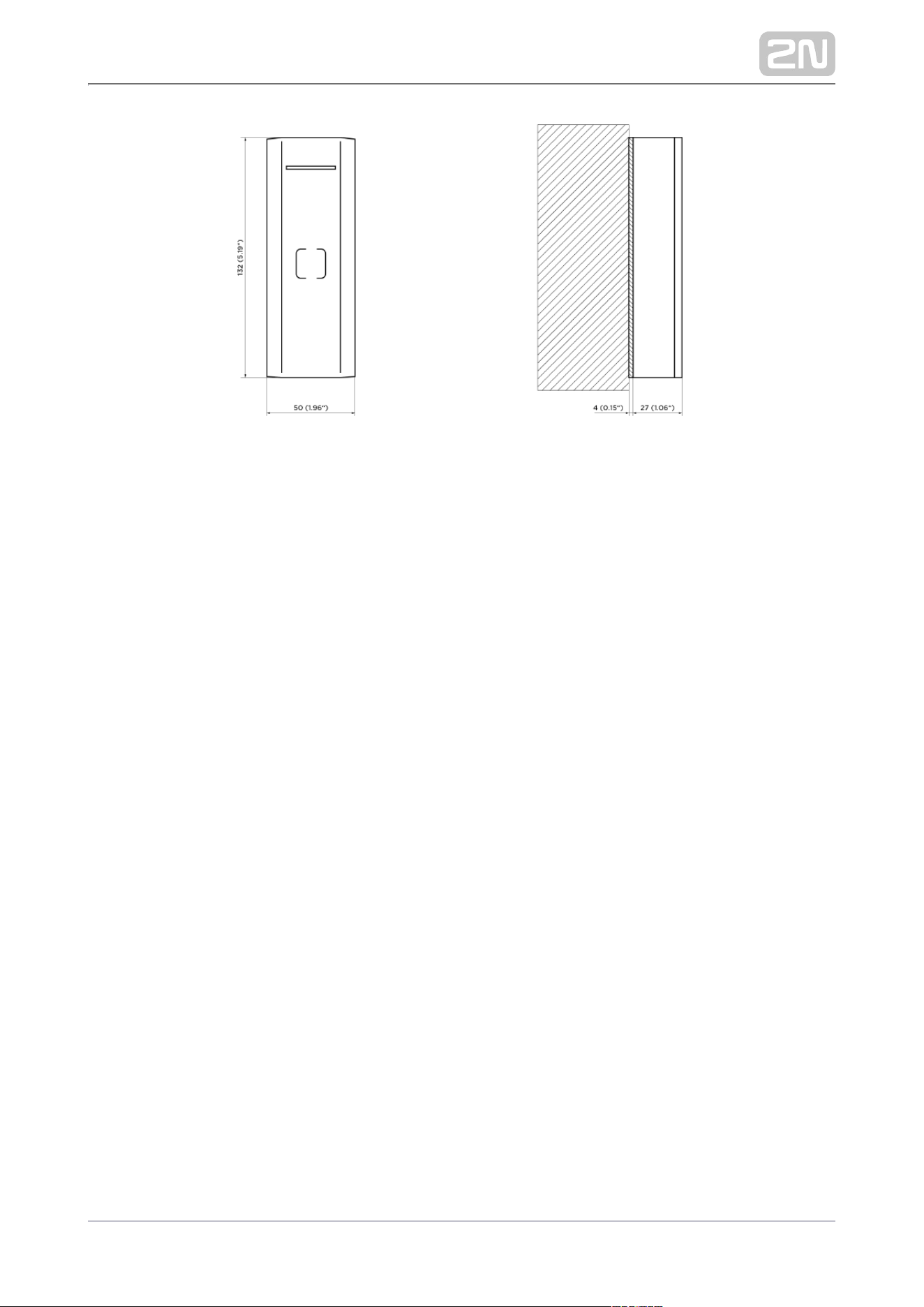
Dimensions: 132 (H) x 50 (W) x 27 (D) [mm]
Weight: 460 g
Covering level: IP55
2N TELEKOMUNIKACE a.s., www.2n.cz 48/56
7.1 General Drawings
2N TELEKOMUNIKACE a.s., www.2n.cz 49/56


2N TELEKOMUNIKACE a.s., www.2n.cz 51/56
8.1 General Instructions and Cautions
Please read this User Manual carefully before using the product. Follow all instructions
and recommendations included herein.
Any use of the product that is in contradiction with the instructions provided herein
may result in malfunction, damage or destruction of the product.
The manufacturer shall not be liable and responsible for any damage incurred as a
result of a use of the product other than that included herein, namely undue
application and disobedience of the recommendations and warnings in contradiction
herewith.
Any use or connection of the product other than those included herein shall be
considered undue and the manufacturer shall not be liable for any consequences
arisen as a result of such misconduct.
Moreover, the manufacturer shall not be liable for any damage or destruction of the
product incurred as a result of misplacement, incompetent installation and/or undue
operation and use of the product in contradiction herewith.
The manufacturer assumes no responsibility for any malfunction, damage or
destruction of the product caused by incompetent replacement of parts or due to the
use of reproduction parts or components.
The manufacturer shall not be liable and responsible for any loss or damage incurred
as a result of a natural disaster or any other unfavourable natural condition.
The manufacturer shall not be held liable for any damage of the product arising during
the shipping thereof.
The manufacturer shall not make any warrant with regard to data loss or damage.
The manufacturer shall not be liable and responsible for any direct or indirect damage
incurred as a result of a use of the product in contradiction herewith or a failure of the
product due to a use in contradiction herewith.
All applicable legal regulations concerning the product installation and use as well as
provisions of technical standards on electric installations have to be obeyed. The
manufacturer shall not be liable and responsible for damage or destruction of the
product or damage incurred by the consumer in case the product is used and handled
contrary to the said regulations and provisions.
The consumer shall, at its own expense, obtain software protection of the product.
The manufacturer shall not be held liable and responsible for any damage incurred as
a result of the use of deficient or substandard security software.

2N TELEKOMUNIKACE a.s., www.2n.cz 52/56
The consumer shall, without delay, change the access password for the product after
installation. The manufacturer shall not be held liable or responsible for any damage
incurred by the consumer in connection with the use of the original password.
The manufacturer also assumes no responsibility for additional costs incurred by the
consumer as a result of making calls using a line with an increased tariff.
Electric Waste and Used Battery Pack Handling
Do not place used electric devices and battery packs into municipal waste containers.
An undue disposal thereof might impair the environment!
Deliver your expired electric appliances and battery packs removed from them to
dedicated dumpsites or containers or give them back to the dealer or manufacturer
for environmental-friendly disposal. The dealer or manufacturer shall take the product
back free of charge and without requiring another purchase. Make sure that the
devices to be disposed of are complete.
Do not throw battery packs into fire. Battery packs may not be taken into parts or
short-circuited either.


2N TELEKOMUNIKACE a.s., www.2n.cz 54/56
8.3 Directives, Laws and Regulations
2N Access Unit M
®
conforms to the following directives and regulations:
2014/53/EU for radio equipment
2011/65/EU on the restriction of the use of certain hazardous substances in
electrical and electronic equipment
2012/19/EU on waste electrical and electronic equipment
Industry Canada
This Class A digital apparatus complies with Canadian ICES-003/NMB-003.
FCC
This equipment has been tested and found to comply with the limits for a Class A
digital device, pursuant to part 15 of the FCC Rules.
NOTE: These limits are designed to provide reasonable protection against harmful
interference in a residential installation. This equipment generates, uses and can
radiate radio frequency energy and, if not installed and used in accordance with the
instructions, may cause harmful interference to radio communications.
However, there is no guarantee that interference will not occur in a particular
installation. If this equipment does cause harmful interference to radio or television
reception, which can be determined by turning the equipment off and on, the user is
encouraged to try to correct the interference by one or more of the following
measures:
Reorient or relocate the receiving antenna
Increase the separation between the equipment and receiver
Connect the equipment into an outlet on a circuit different from that to which
the receiver is connected
Consult the dealer or an experienced radio/TV technician for help
Changes or modifications to this unit not expressly approved by the party responsible
for compliance could void the user's authority to operate this equipment.
Warning
In order to ensure the full functioning and guaranteed outputs we strongly
recommend a verification of the timeliness of version of product or facility already
during the installation process. The customer takes into consideration that the product
or facility can achieve the guaranteed outputs and be fully operational pursuant to the
producer’s instructions only by using the most recent version of product or facility,

2N TELEKOMUNIKACE a.s., www.2n.cz 55/56
which has been tested for full interoperability and has not been determined by the
producer as incompatible with certain versions of other products, only in conformity
with the producer’s instructions, guidelines, manual or recommendation and only in
conjunction with suitable products and facilities of the other producers. The most
recent versions are available on the website https://www.2n.cz/cs_CZ/, or specific
facilities, depending on their technical capacity, allow updating in the configuration
interface. Should the customer use any other version of product or facility than the
most recent one, or the version that has been determined by the producer as
incompatible with certain versions of other producers’ products of facilities, or the
product or facility in a way incompatible with the producer’s instructions, guidelines,
manual or recommendation or in conjunction with unsuitable products or facilities of
the other producers, he or she is aware of all potential limitations of functionality of
such a product or facility and all relating consequences. Should the customer use any
other than the most recent version of the product or facility, or the version that has
been that has been determined by the producer as incompatible with certain versions
of other producers’ products of facilities, or the product or facility in a way
incompatible with the producer’s instructions, guidelines, manual or recommendation
or in conjunction with unsuitable products or facilities of the other producers, he or
she agrees that the company 2N TELEKOMUNIKACE a.s. is not liable neither for any
limitation of such a product’s functionality, nor for any damage, loss or injury relating
to such a potential limitation of functionality.

2N TELEKOMUNIKACE a.s., www.2n.cz 56/56
2N TELEKOMUNIKACE a.s.
Modřanská 621, 143 01 Prague 4, Czech Republic
Phone: +420 261 301 500, Fax: +420 261 301 599
E-mail: [email protected]
Web: www.2n.cz
v1.0