

2N Access Unit Installation Manual
2 / 118
•
•
•
•
•
•
•
•
•
•
•
•
•
•
•
•
•
•
•
•
•
Content:
1. Product Overview
1.1 Components and Associated Products
1.2 Terms and Symbols
2. Description and Installation
2.1 Before You Start
2.2 Mechanical Installation
2.2.1 One Module Box
2.2.2 Two Module Box
2.2.3 Module dimensions
2.3 Electric Installation
2.3.1 Overvoltage Protection
2.4 Extending Module Connection
2.5 Mounting Completion
3. Maintenance
4. Technical Parameters
4.1 General drawings
5. Supplementary Information
5.1 Troubleshooting
5.2 Directives, Laws and Regulations
5.3 Other Countries' Legislation
5.4 General Instructions and Cautions

2N Access Unit Installation Manual
3 / 118
•
•
•
•
•
•
•
1. Product Overview
Here is what you can find in this section:
1.1 Components and Associated Products
1.2 Terms and Symbols
Basic Properties
2NAccess Unitis an elegant and reliable access IP system equipped with a number of useful
functions, which are not always common in devices of this category.
2NAccess Unitis a modular access system that meets all individual user needs. Unlike other
access systems available on the market,2NAccess Unitis not a single-module system with a
fixed functionality, but a user friendly modular system, allowing the user to assemble required
modules and accessories on a “plug and play” basis. This approach provides individual
configuration options and increase in functionality as necessary.
Keypadis a numeric keypad module that allows you to use the device for code lock switch
activation.
Integrated card reader moduleprovides the RFID card access control functionality. With
additional software settings, you can control more functions than the door lock using the card.
Electric lock switch –this switch can be can be controlled via a numeric keypad or Automation
actions. The switch can be completed with additional output modules if necessary. A wide range
of the switch mode settings provide an infinite number of applications.
Resistance–2NAccess Unitis designed as a robust, mechanically resistant access system,
which withstands any weather conditions without requiring additional accessories.
Installation of2NAccess Unitis very easy. All you have to do is assemble the required modules
and connect the system to your LAN via a mains cable. Being of the “plug and play” type, the
modules need not be configured individually. Feed the intercom either from a 12 V power supply
or directly from your PoE-supporting LAN.
To configure 2NAccess Unit, you need a PC equipped with any Internet browser. To manage
extensive intercom installations easily, use the2N
Access Commander.
Advantages of Use
Elegant design
Weather resistance
Variable mounting options (brick/plasterboard flush mounting, wall mounting)
Optional numeric keypad with backlight
Use of multiple modules of the same type – e.g. building entrance/exit card reader

2N Access Unit Installation Manual
4 / 118
•
•
•
•
•
•
•
•
•
•
•
•
•
Integrated electronic lock switches with wide setting options
Integrated RFID card reader module, Bluetooth module, fingerprint reader module or
touch keypad module
LAN (PoE) or external 12 V power supply
Configuration via web interface
HTTP server for configuration
SNTP client for server time synchronisation
SMTP client for e-mail sending
TFTP/HTTP client for automatic configuration and firmware update
1.1 Components and Associated Products
Basic Units
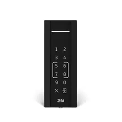
2N Part No. 9160341
2N
®
Access Unit 2.0 125 kHz
The card reader provides you with access control via
contactless cards or keyfobs. The module supports the 125
kHz EM4xxx.
2N Part No. 9160341US
Axis Part No. 02137-001
2N
®
Access Unit 2.0 125 kHz
The card reader provides you with access control via
contactless cards or keyfobs. The module supports the 125
kHz EM4xxx.
Reads HID Proximity
2N Access Unit Installation Manual
5 / 118
•
•
•
•
•
•
•
•
•
•
•
•
•
•
•
•
•
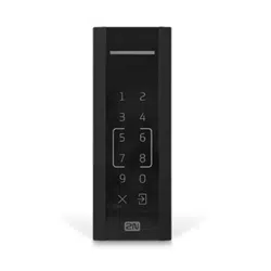
2N Part No. 9160342
Axis Part No. 02143-001
2N
®
Access Unit 2.0 13.56 MHz, NFC ready
The card reader module provides you with access control via
contactless cardsorkeyfobs. The module supports the
following 13.56 MHz cards or other carriers (only card serial
number is read):
ISO14443A (MIFARE DESFire)
PicoPass (HID iClass)
FeliCa
ST SR(IX)
2N
®
Mobile Key
2N Part No. 9160342-S
Axis Part No. 02142-001
2N
®
Access Unit 2.0 13.56 MHz, securedNFC ready
The card reader module provides you with access control via
contactless cardsorkeyfobs. The module supports the
following 13.56 MHz cards or other carriers (only card serial
number is read):
ISO14443A (MIFARE DESFire)
PicoPass (HID iClass)
FeliCa
ST SR(IX)
2N
®
Mobile Key
HID SE (Seos, iClass SE, MIFARE SE)
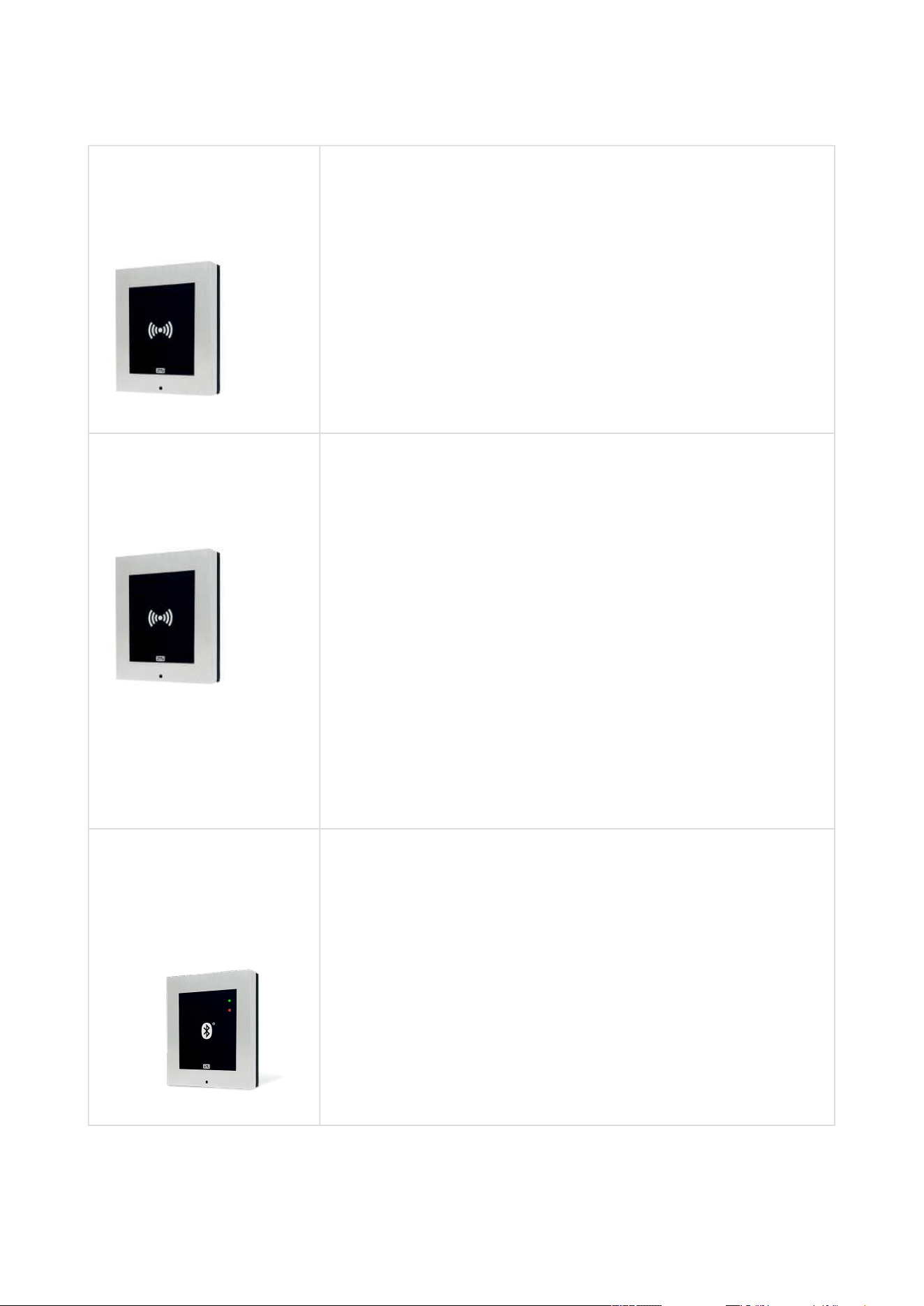
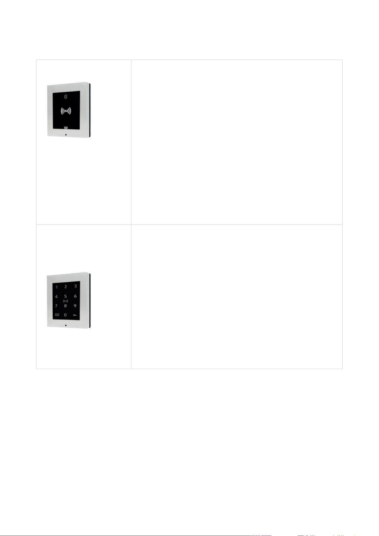
2N Part No. 916013
Axis Part No. 01368-001
2N
®
Access Unit Bluetooth
The Bluetooth reader is used for reading users secure ID
numbers from the 2N
®
Mobile Key application of smart
phones Android and iOS.
2N Access Unit Installation Manual
6 / 118
•
•
•
•
•
•
•
•
•
•
•
•
•
•
•
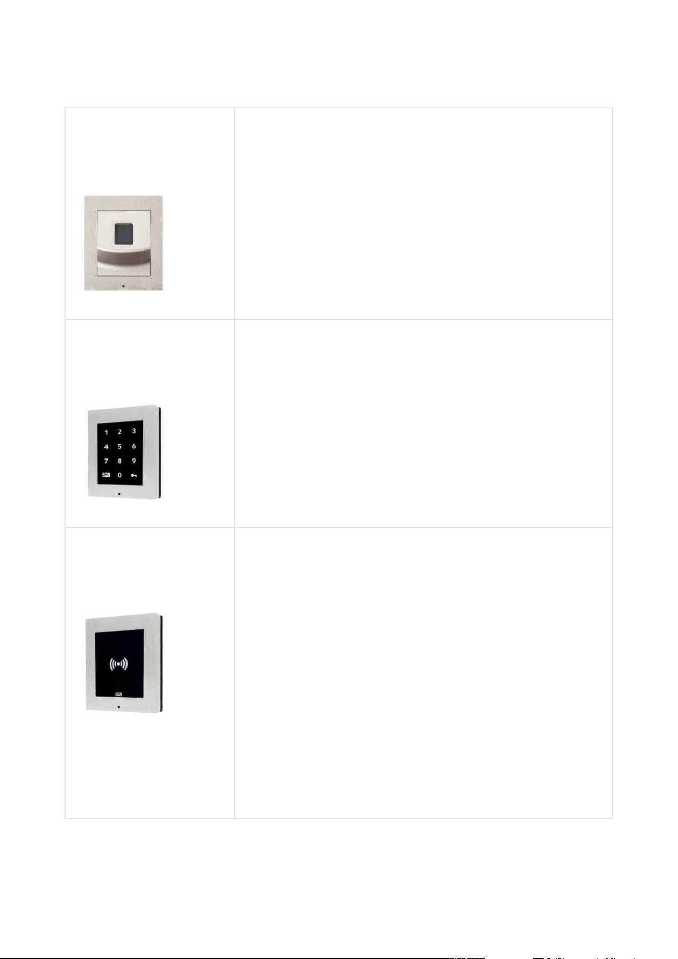
2N Part No. 916031
Axis Part No. 02263-001
2N
®
Access Unit 2.0 Fingerprint reader
The Fingerprint reader is used for verification of human
fingers for access control and intercom control.
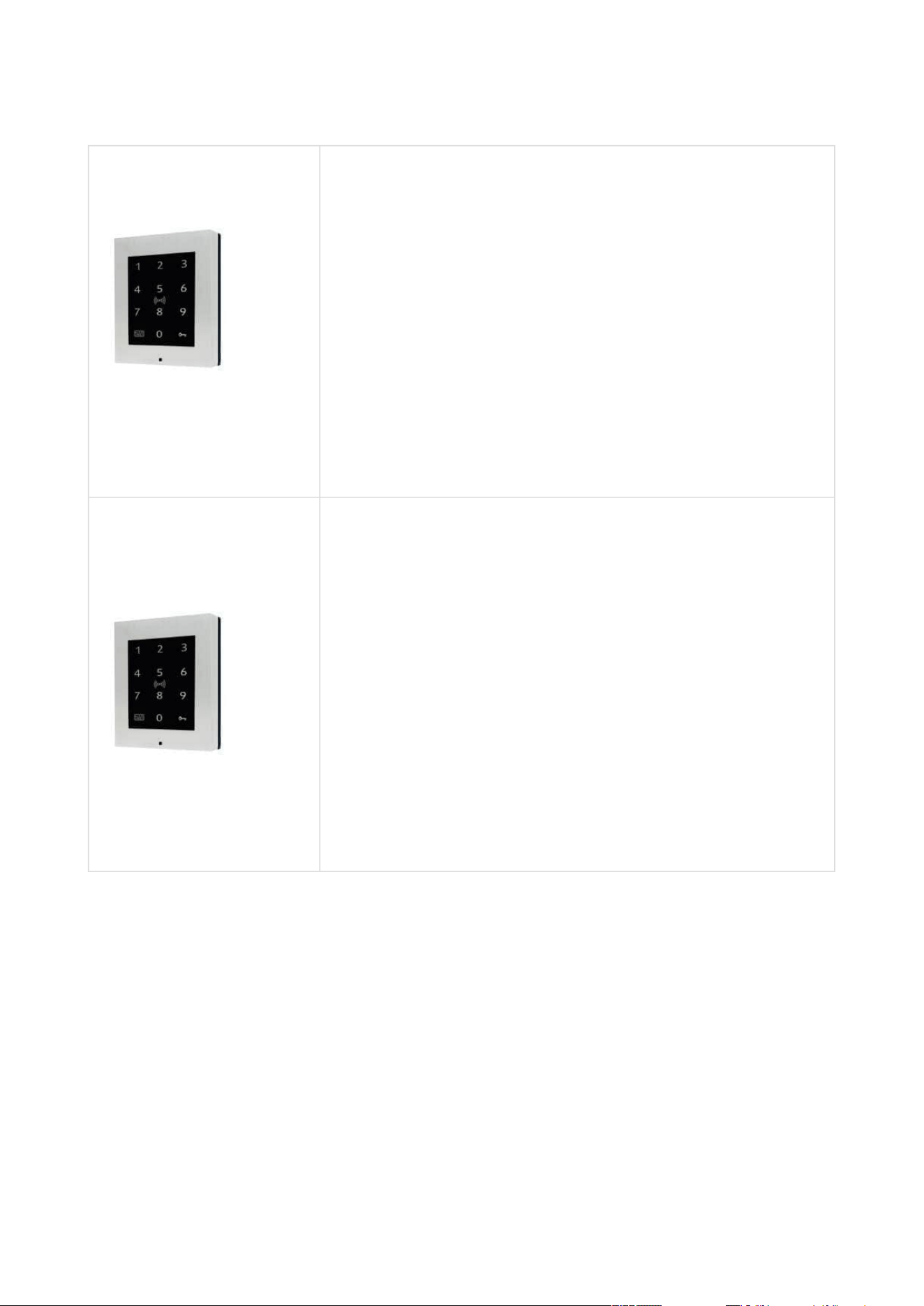
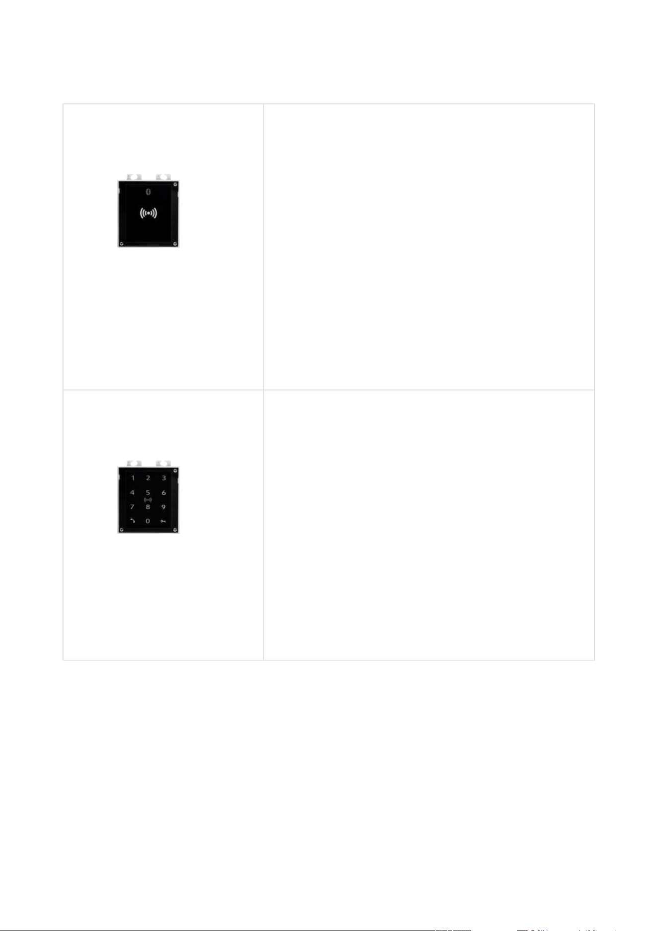
2N Part No. 916032
Axis Part No. 02262-001
2N
®
Access Unit 2.0 Touch keypad
The numeric touch keypad module helps you control the
lock and use other code-accessible functions. The keypad
digits and symbols are backlit.
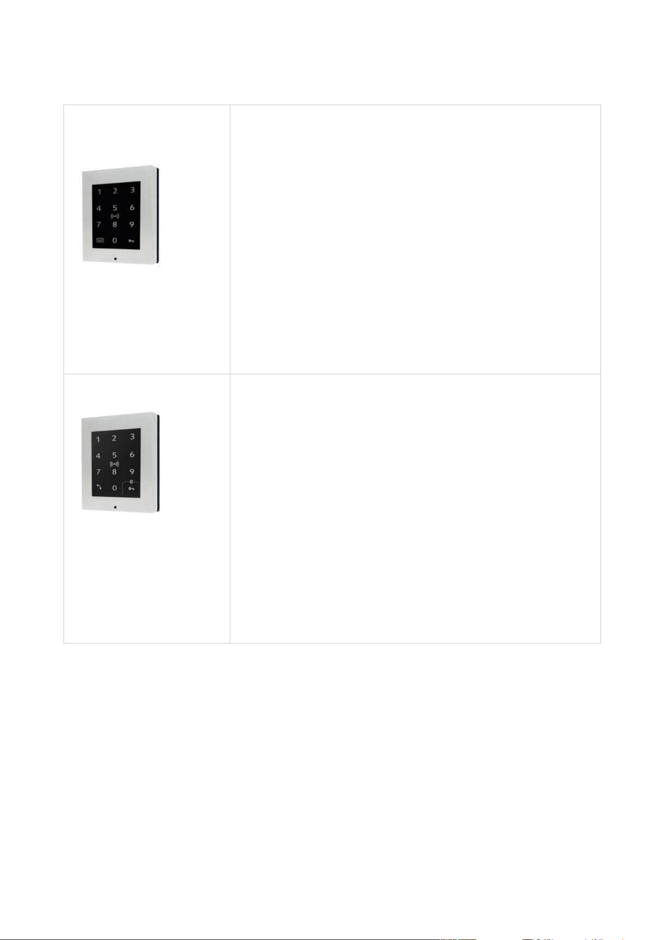
2N Part No. 9160344
Axis Part No. 02138-001
2N
®
Access Unit 2.0 RFID – 125 kHz, 13.56 MHz, NFC
The card reader provides you with access control via
contactless cards or keyfobs. The module supports the 125
kHz EM-41xx.
The card reader module provides you with access control via
contactless cardsorkeyfobs. The module supports the
following 13.56 MHz cards or other carriers (only card serial
number is read):
125 kHz
EM4xxx
13.56 MHz
ISO14443A (MIFARE DESFire)
PicoPass (HID iClass)
FeliCa
ST SR(IX)
2N
®
Mobile Key

2N Access Unit Installation Manual
7 / 118
•
•
•
•
•
•
•
•
•
•
•
•
•
•
•
•
•
•
•
•
•
2N Part No. 9160344-S
Axis Part No. 02146-001
2N
®
Access Unit 2.0 RFID – 125 kHz, secured 13.56 MHz,
NFC
The card reader provides you with access control via
contactless cards or keyfobs. The module supports the 125
kHz EM-41xx.
The card reader module provides you with access control via
contactless cardsorkeyfobs. The module supports the
following 13.56 MHz cards or other carriers (only card serial
number is read):
125 kHz
EM4xxx
13.56 MHz
ISO14443A (MIFARE DESFire)
PicoPass (HID iClass)
FeliCa
ST SR(IX)
2N
®
Mobile Key
HID SE (Seos, iClass SE, MIFARE SE)
2N Part No. 9160345
2N
®
Access Unit 2.0 Bluetooth & RFID – 125 kHz, 13.56
MHz, NFC
The combined Bluetooth & card reader module provides
access control using an access code, the 2N
®
Mobile Key
application in your smartphone or an access card. The
module supports the following 125 kHz and 13.56 MHz cards
or other carriers (only card serial number is read):
125 kHz
EM4xxx
13.56 MHz
ISO14443A (MIFARE DESFire)
PicoPass (HID iClass)
FeliCa
ST SR(IX)
2N
®
Mobile Key
2N Access Unit Installation Manual
8 / 118
•
•
•
•
•
•
•
•
•
•
•
•
•
•
•
•
•
•
•
•
•
obj. č.9160345-S
2N
®
Access Unit 2.0 Bluetooth & RFID – 125 kHz, secured
13.56 MHz, NFC
The combined Bluetooth & card reader module provides
access control using an access code, the 2N
®
Mobile Key
application in your smartphone or an access card. Modul
podporuje karty nebo jiné nosiče frekvence 125 kHz a 13.56
MHz standardů.
125 kHz
EM4xxx
13.56 MHz
ISO14443A (MIFARE DESFire)
PicoPass (HID iClass)
FeliCa
ST SR(IX)
2N
®
Mobile Key
HID SE (Seos, iClass SE, MIFARE SE)
2N Part No. 9160336
Axis Part No. 02546-001
2N
®
Access Unit 2.0 Touch keypad & RFID – 125 kHz, 13.56
MHz, NFC
The touch keypad and card reader module provides you
with access control via contactless cards or keyfobs. The
module supports the following125 kHz and13.56 MHz cards
or other carriers (only card serial number is read):
125 kHz
EM4xxx
13.56 MHz
ISO14443A (MIFARE DESFire)
PicoPass (HID iClass)
FeliCa
ST SR(IX)
2N
®
Mobile Key
2N Access Unit Installation Manual
9 / 118
•
•
•
•
•
•
•
•
•
•
•
•
•
•
•
•
•
•
•
•
•
2N Part No. 9160346
2N
®
Access Unit 2.0 Touch keypad & RFID – 125 kHz, 13.56
MHz, NFC
The touch keypad and card reader module provides you
with access control via contactless cards or keyfobs. The
module supports the following125 kHz and13.56 MHz cards
or other carriers (only card serial number is read):
125 kHz
EM4xxx
13.56 MHz
ISO14443A (MIFARE DESFire)
PicoPass (HID iClass)
FeliCa
ST SR(IX)
2N
®
Mobile Key
2N Part No. 9160336-S
Axis Part No. 01852-001
2N
®
Access Unit 2.0 Touch keypad & RFID – 125 kHz,
secured 13.56 MHz, NFC
The touch keypad and card reader module provides you
with access control via contactless cards or keyfobs. The
module supports the following125 kHz and13.56 MHz cards
or other carriers (only card serial number is read):
125 kHz
EM4xxx
13.56 MHz
ISO14443A (MIFARE DESFire)
PicoPass (HID iClass)
FeliCa
ST SR(IX)
2N
®
Mobile Key
HID SE (Seos, iClass SE, MIFARE SE)
2N Access Unit Installation Manual
10 / 118
•
•
•
•
•
•
•
•
•
•
•
•
•
•
2N Part No. 9160346-S
2N
®
Access Unit 2.0 Touch keypad & RFID – 125 kHz,
secured 13.56 MHz, NFC
The touch keypad and card reader module provides you
with access control via contactless cards or keyfobs. The
module supports the following125 kHz and13.56 MHz cards
or other carriers (only card serial number is read):
125 kHz
EM4xxx
13.56 MHz
ISO14443A (MIFARE DESFire)
PicoPass (HID iClass)
FeliCa
ST SR(IX)
2N
®
Mobile Key
HID SE (Seos, iClass SE, MIFARE SE)
2N Part No. 9160347 2N® Access Unit 2.0 Touch keypad & Bluetooth & RFID -
125 kHz, 13.56 MHz, NFC
The combined keypad & Bluetooth & card reader module
provides access control using an access code, the 2N
®
Mobile Key application in your smartphone or an access
card. The module supports 125 kHz and 13.56 MHz cards or
other carriers of the same frequencies:
125 kHz
EM4xxx
13.56 MHz
ISO14443A (MIFARE DESFire)
PicoPass (HID iClass)
FeliCa
ST SR(IX)
2N
®
Mobile Key

2N Access Unit Installation Manual
11 / 118
•
•
•
•
•
2N Part No. 9160347-S 2N® Access Unit 2.0 Touch keypad & Bluetooth & RFID -
125kHz, secured 13.56 MHz, NFC
The combined keypad & Bluetooth & card reader module
provides access control using an access code, the 2N
®
Mobile Key application in your smartphone or an access
card. The module supports 125 kHz and 13.56 MHz cards or
other carriers of the same frequencies:
125 kHz
EM4xxx
13.56 MHz
ISO14443A (MIFARE DESFire)
PicoPass (HID iClass)
FeliCa
ST SR(IX)
2N
®
Mobile Key
HID SE (Seos, iClass SE, MIFARE SE)
License
2N Part No. 916012
Axis Part No.
01369-001
2NAccess Unit license
2N Part No. 9160401
2N Access Unit Lift module license
•
Tip
Supported auxiliary modules: 2N
®
IP Verso modules are supported – RFID card
reader (125 kHz; 13.56 MHz), keypad, 5-button module, Wiegand, etc.

2N Access Unit Installation Manual
12 / 118
•
•
•
•
•
•
Frames
2N Part No. 9155011
Axis Part No. 01278-001
Flush mounting frame, 1-module
Covering frame for the 1-module brick/plasterboard
flush mounting box. This 1-module frame is used for
connection of an OUT card reader or keypad, for
example. Remember to order the frame when you
order a 1-module flush mounting box, Part No.
9155014.
2N Part No.9155011B
Axis Part No. 01279-001
Flush mounting frame, 1-module
Covering frame for the 1-module brick/plasterboard
flush mounting box. This 1-module frame is used for
connection of an OUT card reader or keypad, for
example. Remember to order the frame when you
order a 1-module flush mounting box, Part No.
9155014.
2N Part No. 9155012
Axis Part No. 01281-001
Flush mounting frame, 2-module
Covering frame for the 2-module brick/plasterboard
flush mounting box. Remember to order the frame
when you order a 2-module flush mounting box, Part
No. 9155015.

2N Access Unit Installation Manual
13 / 118
•
•
•
•
2N Part No.9155012B
Axis Part No. 01282-001
Flush mounting frame, 2-module
Covering frame for the 2-module brick/plasterboard
flush mounting box. Remember to order the frame
when you order a 2-module flush mounting box, Part
No. 9155015.
2N Part No. 9155021
Axis Part No. 01287-001
Wall mounting frame, 1-module
Covering frame for wall (surface) mounting.This 1-
module frame is used for connection of an OUT card
reader or keypad, for example.

2N Access Unit Installation Manual
14 / 118
•
•
2N Part No.9155021B
Axis Part No. 01288-001
Wall mounting frame, 1-module
Covering frame for wall (surface) mounting.This 1-
module frame is used for connection of an OUT card
reader or keypad, for example.

2N Access Unit Installation Manual
15 / 118
•
•
•
•
2N Part No. 9155022
Axis Part No. 01289-001
Wall mounting frame, 2-module
Covering frame for wall (surface) mounting.
2N Part No.9155022B
Axis Part No. 01290-001
Wall mounting frame, 2-module
Covering frame for wall (surface) mounting.

2N Access Unit Installation Manual
16 / 118
•
•
•
Extending Modules
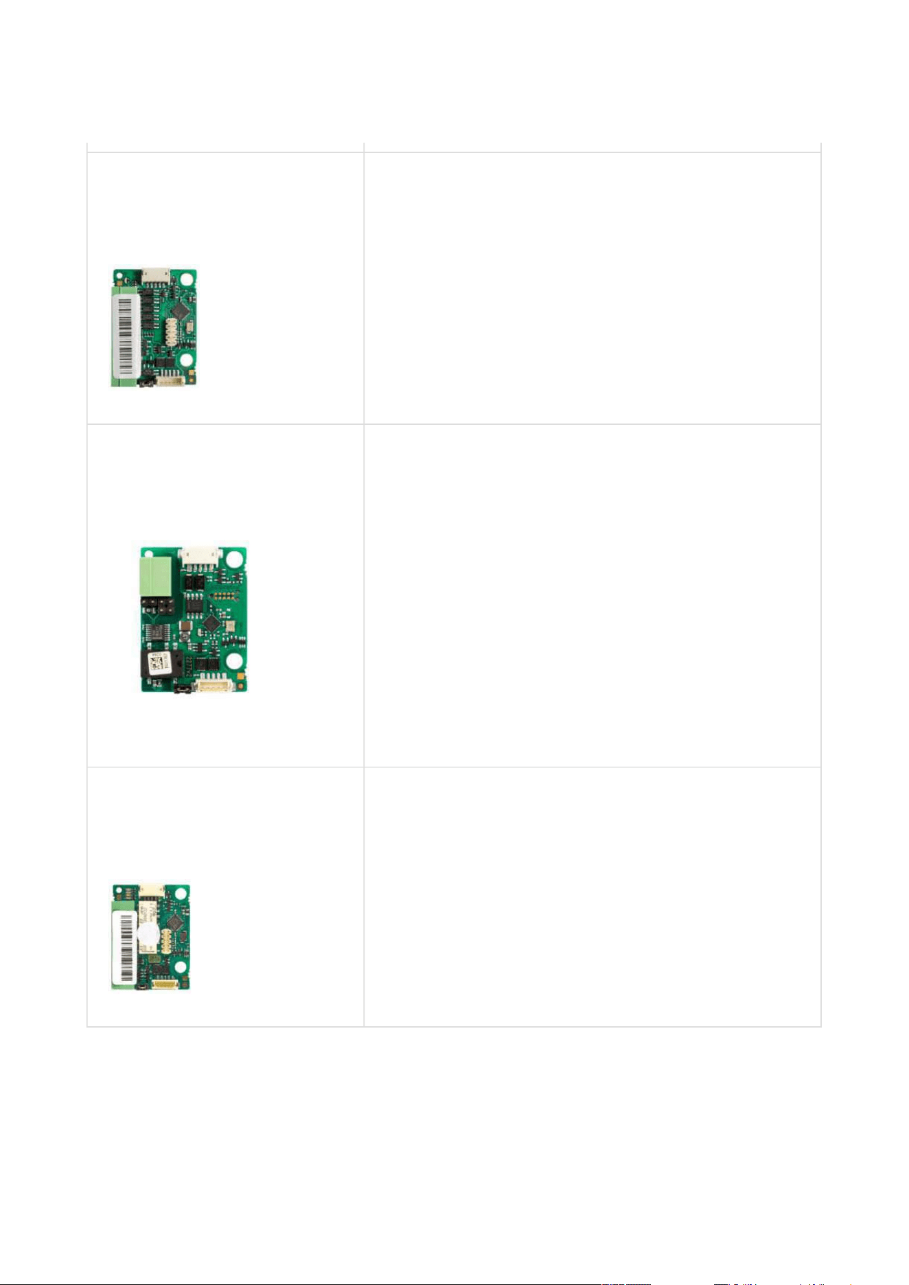
2N Part No. 916020
Axis Part No. 01371-001
RJ-45 adapter
2N Part No.9155032
Axis Part No. 01255-001
2N
®
IP Verso – RFID Reader, 125 kHz
The card reader module works with 2N
Access Unitas
an OUT card reader. The module supports cards, key
fobs and/or other 125 kHz standard carriers: EM4xxx.
•
Tip
The 1-module frame is used when an auxiliary module from 2N
®
IP Verso is
mounted onto an extended interconnecting cable, for an OUT card reader or
keypad, for example.
•
•
•
Tip
Remember to order the flush mounting frame when you order a brick/plasterboard
flush mounting box:
1-module frame, Part No. 9155011 – 1-module flush mounting box, Part No.
9155014.
2-module frame, Part No. 9155012 –2-module flush mounting box, Part No.
9155015.

2N Access Unit Installation Manual
17 / 118
•
•
•
•
•
•
•
•
•
•
•
•
•
•
•
•
•
2N Part No. 9155040
Axis Part No. 01262-001
2N
®
IP Verso– RFID Reader NFC/HCE support, 13.56
MHz
The card reader module works with 2N
Access Unit as
an OUT card reader. The module supports cards, key
fobs and/or other 13.56 MHz standard carriers (only
card serial number is read):
ISO14443A (MIFARE DESFire)
PicoPass (HID iClass)
FeliCa
ST SR(IX)
2N
®
Mobile Key
Part No. 9155082
2N
®
IP Verso – Bluetooth & RFID reader 125 kHz,
13.56 MHz, NFC/HCE
The bluetooth and card reader module works with
2N
Access Unit as an OUT card reader. The module
supports cards, key fobs and/or other 125 kHz and
13.56 MHz standard carriers (only card serial number
is read):
125 kHz
EM4xxx
13.56 MHz
ISO14443A (MIFARE DESFire)
PicoPass (HID iClass)
FeliCa
ST SR(IX)
2N
®
Mobile Key
2N Access Unit Installation Manual
18 / 118
•
•
•
•
•
•
•
•
•
•
•
•
•
•
•
•
•
•
•
•
•
Part No. 9155084
2N
®
IP Verso – Bluetooth & RFID reader 125 kHz,
secured 13.56 MHz, NFC/HCE
The bluetooth and secured card reader module works
with 2N
Access Unit as an OUT card reader. The
module supports cards, key fobs and/or other 125 kHz
and 13.56 MHz standard carriers (only card serial
number is read):
125 kHz
EM4xxx
13.56 MHz
ISO14443A (MIFARE DESFire)
PicoPass (HID iClass)
FeliCa
ST SR(IX)
2N
®
Mobile Key
HID SE (Seos, iClass SE, MIFARE SE)
Part No. 9155081
2N
®
IP Verso – Touch keypad & RFID reader 125 kHz,
13.56 MHz, NFC/HCE
The touch keypad and card reader module works with
2N
Access Unit as an OUT card reader. The module
supports cards, key fobs and/or other 125 kHz and
13.56 MHz standard carriers (only card serial number
is read):
125 kHz
EM4xxx
13.56 MHz
ISO14443A (MIFARE DESFire)
PicoPass (HID iClass)
FeliCa
ST SR(IX)
2N
®
Mobile Key

2N Access Unit Installation Manual
19 / 118
•
•
•
•
•
•
•
•
•
•
•
•
•
Part No. 9155083
2N
®
IP Verso – Touch keypad & RFID reader 125 kHz,
secured 13.56 MHz, NFC/HCE
The touch keypad and secured card reader module
works with 2N
Access Unit as an OUT card reader.
The module supports cards, key fobs and/or other 125
kHz and 13.56 MHz standard carriers (only card serial
number is read):
125 kHz
EM4xxx
13.56 MHz
ISO14443A (MIFARE DESFire)
PicoPass (HID iClass)
FeliCa
ST SR(IX)
2N
®
Mobile Key
HID SE (Seos, iClass SE, MIFARE SE)
2N Part No. 9155031
Axis Part No. 01253-001
2N
®
IP Verso– Keypad
The numeric keypad module helps enter a numeric
entrance code. Use the keypad for departures or
double entrance authentication. The keypad digits
and symbols are backlit.
2N Access Unit Installation Manual
20 / 118
•
•
•
•
•
•
2N Part No.9155031B
Axis Part No. 01254-001
2N
®
IP Verso– Keypad
The numeric keypad module helps enter a numeric
entrance code. Use the keypad for departures or
double entrance authentication. The keypad digits
and symbols are backlit.
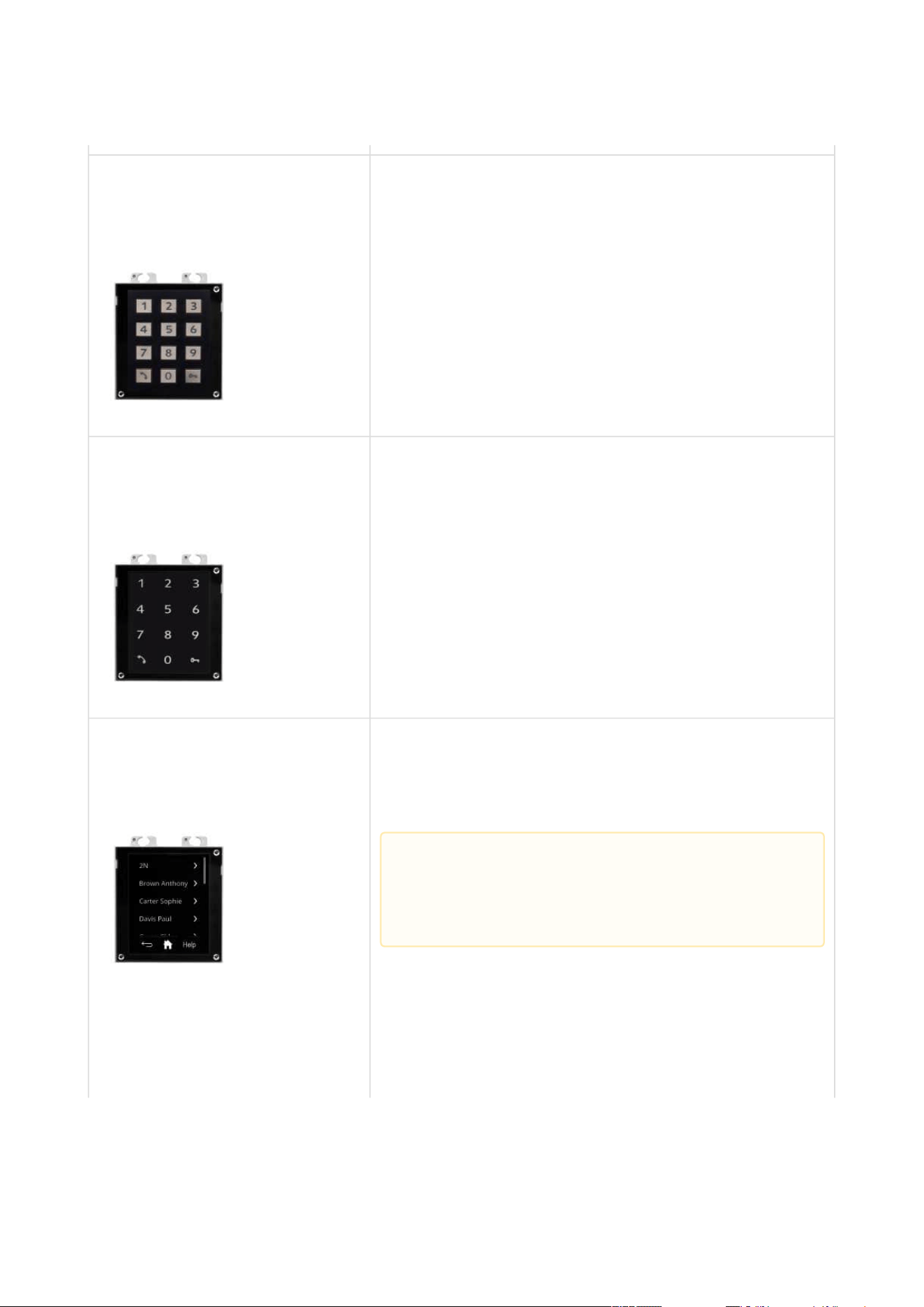
2N Part No.9155047
Axis Part No. 01277-001
2N
®
IP Verso– Touch keypad
The numeric keypad module helps you dial users via
their phonebook positions or phone numbers, control
the lock and use other code-accessible functions. The
keypad digits and symbols are backlit.
2N Part No.9155036
Axis Part No. 01275-001
2N
®
IP Verso – Touch Display
Touchscreen module allowing visitors to dial users in
a smartphone-like way. In addition to a structured
phonebook it also features a keypad.
•
Caution
This module is only supported by 2N Access
Unit 2.0.
2N Access Unit Installation Manual
21 / 118
•
•
•
•
•
•
•
2N Part No. 9155037
Axis Part No. 01259-001
2N
®
IP Verso– Wiegand
The Wiegand module helps you interconnect your
system with other systems (security) via the Wiegand
interface. The module is installed under another
module, i.e. cannot be installed directly into the2N
Access Unit(must be mounted outside).
2N Part No. 91550371
Axis Part No. 02577-001
2N
®
IPVerso– OSDP module
The OSDP moduleprovides communication between
a connected device (control panel, door controller)
and2N
®
IP Versovia the OSDP. The module is
installed under another module, i.e. needs no
separate position.
Compatible with Access Unit 2.0models only
2N Part No. 9155034
Axis Part No. 01257-001
2N
®
IP Verso – I/O
The logic input/output module helps you integrate
various sensors and control doors or other
equipment. The module is installed under another
module, i.e. cannot be installed directly into
the2N
Access Unit (must be mounted outside).
2N Access Unit Installation Manual
22 / 118
•
•
•
•
•
•
•
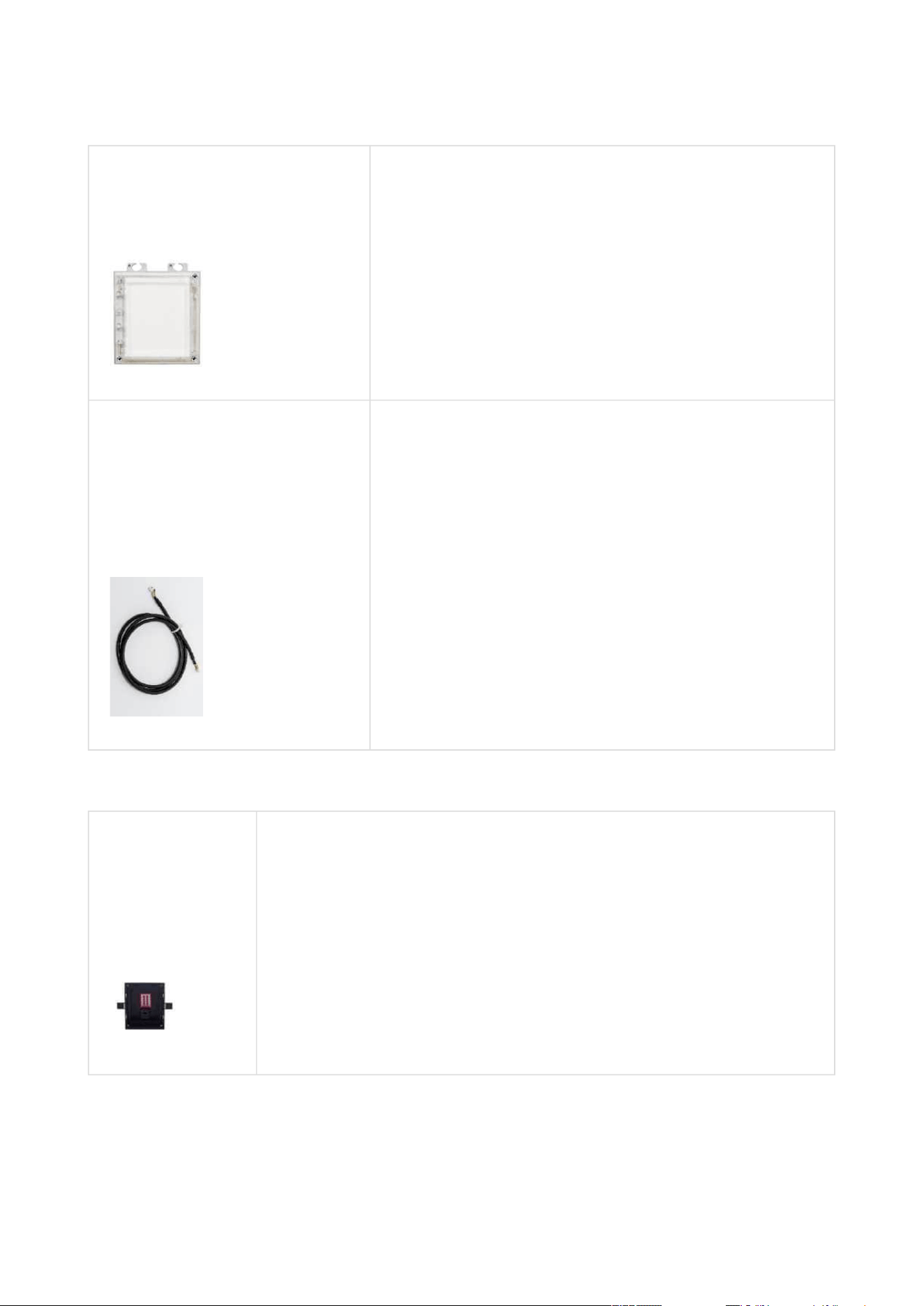
2N Part No.9155030
Axis Part No. 01252-001
2N
®
IP Verso – Info panel
The Infopanel module helps you add your company
logo, opening hours and similar information to the
access unit. The Infopanel has software-controlled
backlight.
Part Numbers:
9155050, 01267-001
9155054, 01268-001
9155055, 01269-001
1 m Interconnecting cable
3 m Interconnecting cable
5 m Interconnecting cable
Mounting Accessories
2N Part
No.9155014
Axis Part No.
01284-001
Flush mounting box, 1-module
The box is designed for brick/plasterboard flush mounting of a 1-
module installation. Supplied including accessories for multiple box
assemblies.

2N Access Unit Installation Manual
23 / 118
•
•
•
•
2N Part
No.9155015
Axis Part No.
01285-001
Flush mounting box, 2-module
The box is designed for brick/plasterboard flush mounting of a 2-
module installation. Supplied including accessories for multiple box
assemblies.
2N Part No.
9155061
Axis Part No.
01293-001
Backplate, 1 module
A backplate for glass or uneven surface mounting.

2N Access Unit Installation Manual
24 / 118
•
•
•
•
•
2N Part No.
9155062
Axis Part No.
01294-001
Backplate, 2 modules
A backplate for glass or uneven surface mounting.
Choose the appropriate mounting frame and box if necessary forthe 2N
Access Unit
installation. The 2N
Access Unit is designed for outdoor applications and requires no additional
roof.
Electric Locks
Part No.932071E
BEFO 11211
12 V / 230 mA DC
low consumption

2N Access Unit Installation Manual
25 / 118
•
•
•
•
•
•
•
•
Part No.932081E
BEFO 11221 with momentum pin
12 V / 230 mA DC
low consumption
For opening of the lock a short electrical impuls is
sufficient, which unlocks the lock. Lock is then open
until someone closes the door.
Part No.932091E
BEFO 11211MB with mechanical blocking
12 V / 230 mA DC
low consumption
Enables mechanically close or open the lock. When
opened, the lock is open all the time. When closed, it
behaves as standart electrical lock.

2N Access Unit Installation Manual
26 / 118
•
•
•
•
•
•
•
•
•
•
Part No. 932061E
211211 door signalling, low consumption
12 V / 230 mA
A regular lock with a built-in contact to indicate
whether the door is open or closed.
Part No. 932072E
31211 fail-safe
12 V / 170 mA DC
The failsafe lock is closed when electricity is switched
on. When electricity is interrupted, the lock is opened.
Part No. 932062E
321211 fail-safe, door signalling
12 V / 170 mA
The failsafe lock is closed when electricity is switched
on. When electricity is interrupted, the lock is opened.
It contains a built-in contact to indicate whether the
door is open or closed.
2N Access Unit Installation Manual
27 / 118
•
•
•
•
•
Power Supply
Part Numbers:
91378100E
91378100US,
01403-001
PoE injetor – with EU cable
PoE injector – with US cable
For intercom power supply viaan Ethernetcable where the PoE switch
is unavailable.
Part No.
91341482E
91341482US
Stabilized 12 V / 1 A power supply needs to be used where no PoE is
available.
Part
No.932928
For external power supply of the lock with 12 V AC voltage.
•
Tip
FAQ:Electric locks – Differences between locks for 2N IP intercoms
2N Access Unit Installation Manual
28 / 118
•
•
•
•
•
•
Additional Modules
2N Part No.9159010
Axis Part No. 01386-001
Security relay
A simple, security enhancing add-on. Prevents lock
tampering. Installed between the intercom, from
which it is also supplied, and the lock to be controlled.
Part No. 9159013
Departure button
Connects the logic input for door unlocking from
inside the building.
2N Part No. 9159012
Axis Part No. 01388-001
Magnetic door contact
A door installation set for door opening status
identification. Used for door protection, open door or
violent door opening detection.

2N Access Unit Installation Manual
29 / 118
•
•
•
2N Part No.9134173
Axis Part No. 01384-001
RFID card, type MIFARE Classic 1k, 13.56 MHz
2N Part No.9134174
Axis Part No. 01385-001
RFID fob, type MIFARE Classic 1k, 13.56 MHz
2N Part No.9134165E
Axis Part No. 01395-001
RFID card, type EM4100, 125 kHz

2N Access Unit Installation Manual
30 / 118
•
•
•
•
•
•
•
•
•
2N Part No.9134166E
Axis Part No. 01396-001
RFID fob, type EM4100, 125 kHz
2N Part No.11202601
Axis Part No.02787-001
2N
®
RFID card Mifare Desfire EV3 4K 13.56MH 10 pcs
10 pcs per package
MIFARE DESFire EV3 (ISO/IEC14443A)
Suitable for data encryption in2N
®
PICard
Commander.
2N Part No.11202602
Axis Part No.02788-001
2N
®
RFID fob Mifare Desfire EV3 4K 13.56MHz 10 pcs
10 pcs per package
MIFARE DESFire EV3 (ISO/IEC14443A)
Suitable for data encryption in2N
®
PICard
Commander.
2N Access Unit Installation Manual
31 / 118
•
•
•
•
•
•
•
•
•
•
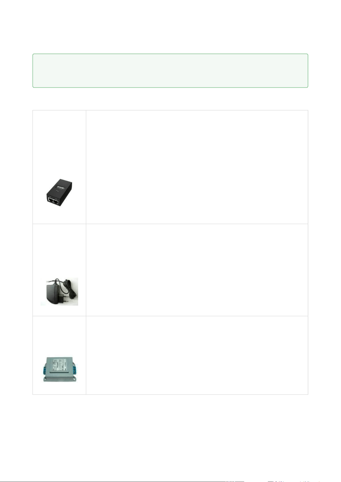
2N Part No.9137420E
Axis Part No. 01399-001
External RFID card reader for connection to PC using a
USB interface.
Suitable for system administration and adding of 125
kHz EM41xx cards using a web interface or 2N
®
Access
Commander.
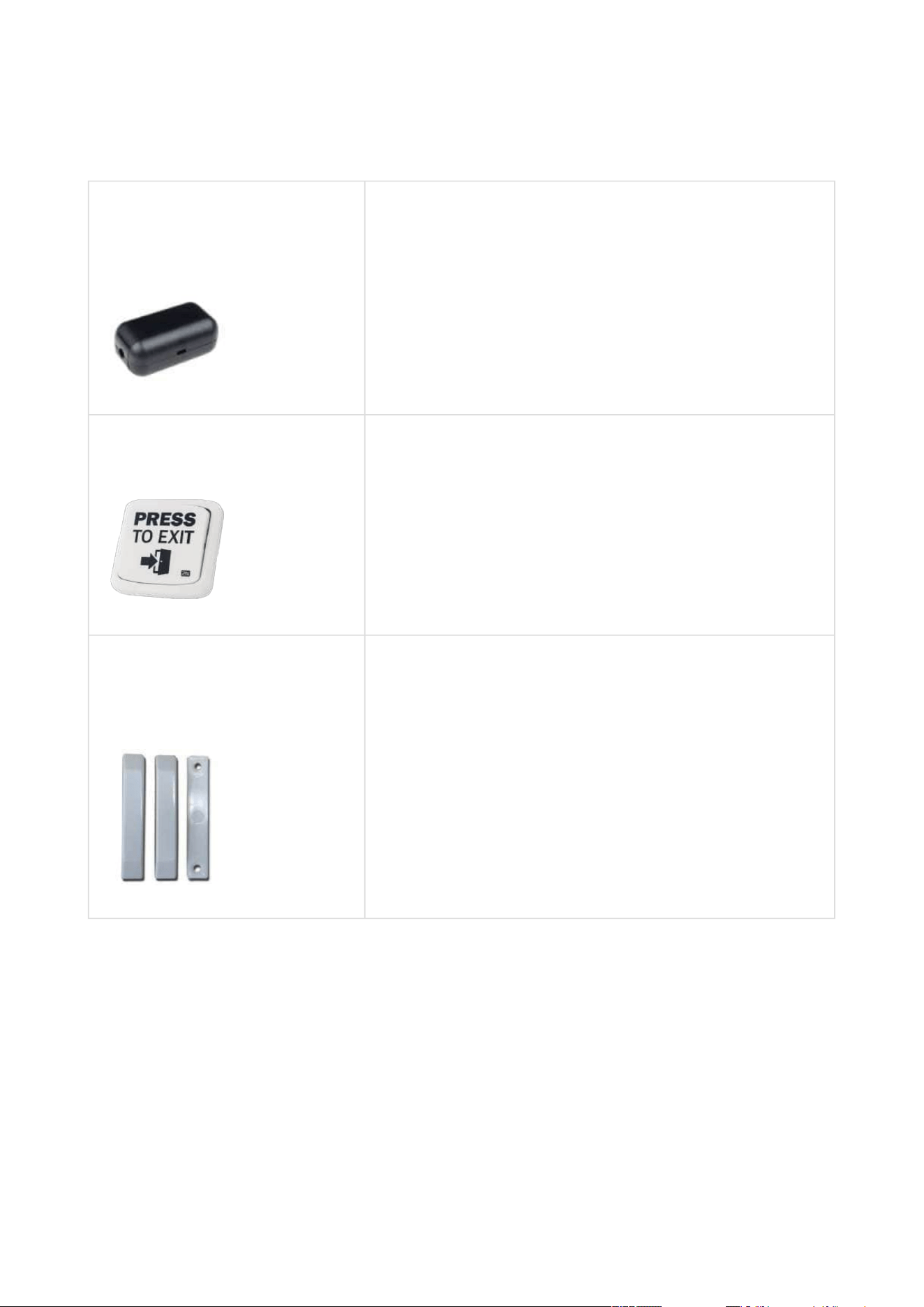
2N Part No. 9137421E
Axis Part No. 01400-001
Ext. RFID Reader 13.56 MHz, 125 kHz + NFC/HCE
(USB interface)
External RFID card reader for PC connection using a
USB interface. Suitable for system administration and
adding of 13.56 MHz, 125 kHz cards and Android
platform devices supporting NFC/HCE using the 2N IP
intercom web interface or 2N
®
Access
Commander.Suitable for MIFARE DESFire card upload
to the2N
®
PICard Commanderencryption
application. It reads the same types of cards and
devices as card readers in the 2N IP intercoms.
13.56 MHz/ISO/IEC 14443A
MIFARE Classic 1k &
4k, MIFARE DESFire EV1, Mini, Plus S&X,
Ultralight, Ultralight C
13.56 MHz/ISO/IEC 14443B
CEPAS, HID iCLASS
(CSN only)
13.56 MHz/JIS X 6319
Felica
125 kHz
EM4xxx
ISO/IEC 18092
SmartPhone with NFC/HCE
support, since Android version 6.0 Marshmallow
(2N
®
Mobile Key app required)
EMarine
2N Access Unit Installation Manual
32 / 118
•
•
•
•
•
•
•
•
•
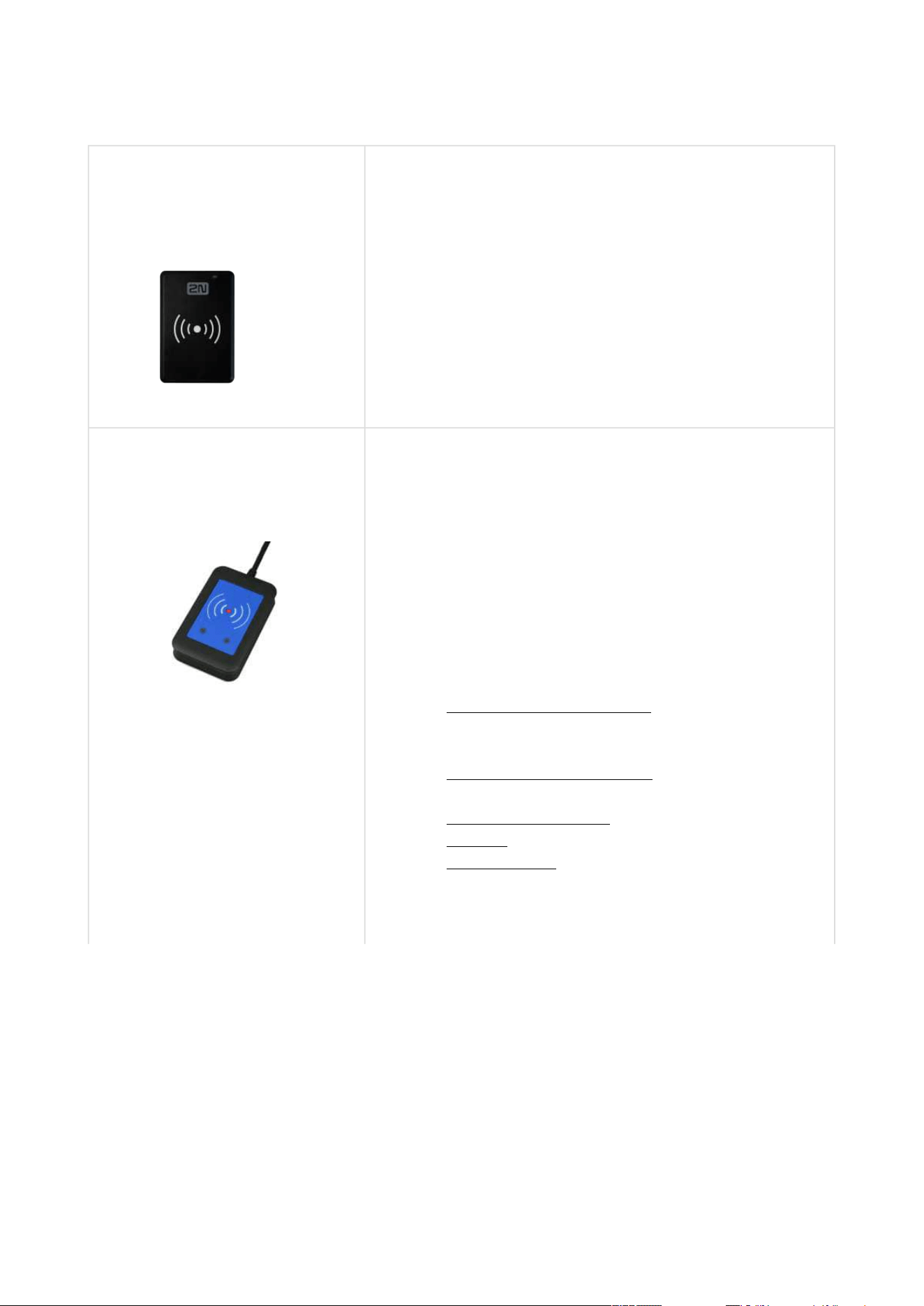
Part No.9137424E
Ext. secured RFID Reader 13.56 MHz, 125 kHz + NFC/
HCE (USB interface)
External secured RFID card reader for PC connection
using a USB interface. Suitable for system
administration and adding of 13.56 MHz, 125 kHz cards
and Android platform devices supporting NFC/HCE
using the 2N IP intercom web interface or 2N
®
Access
Commander.Suitable for MIFARE DESFire card upload
to the2N
®
PICard Commanderencryption
application. It reads the same types of cards and
devices as card readers in the 2N IP intercoms.
13.56 MHz/ISO/IEC
14443A MIFARE Classic 1k &
4k, MIFARE DESFire EV1, Mini, Plus S&X,
Ultralight, Ultralight C
13.56 MHz/ISO/IEC
14443B CEPAS, HID iCLASS
(CSN or PAC ID)
13.56 MHz/JIS X 6319
Felica
125 kHz
EM4xxx, HID Prox
ISO/IEC 18092
SmartPhone with NFC/HCE
support, since Android version 6.0 Marshmallow
(2N
®
Mobile Key app required)
EMarine
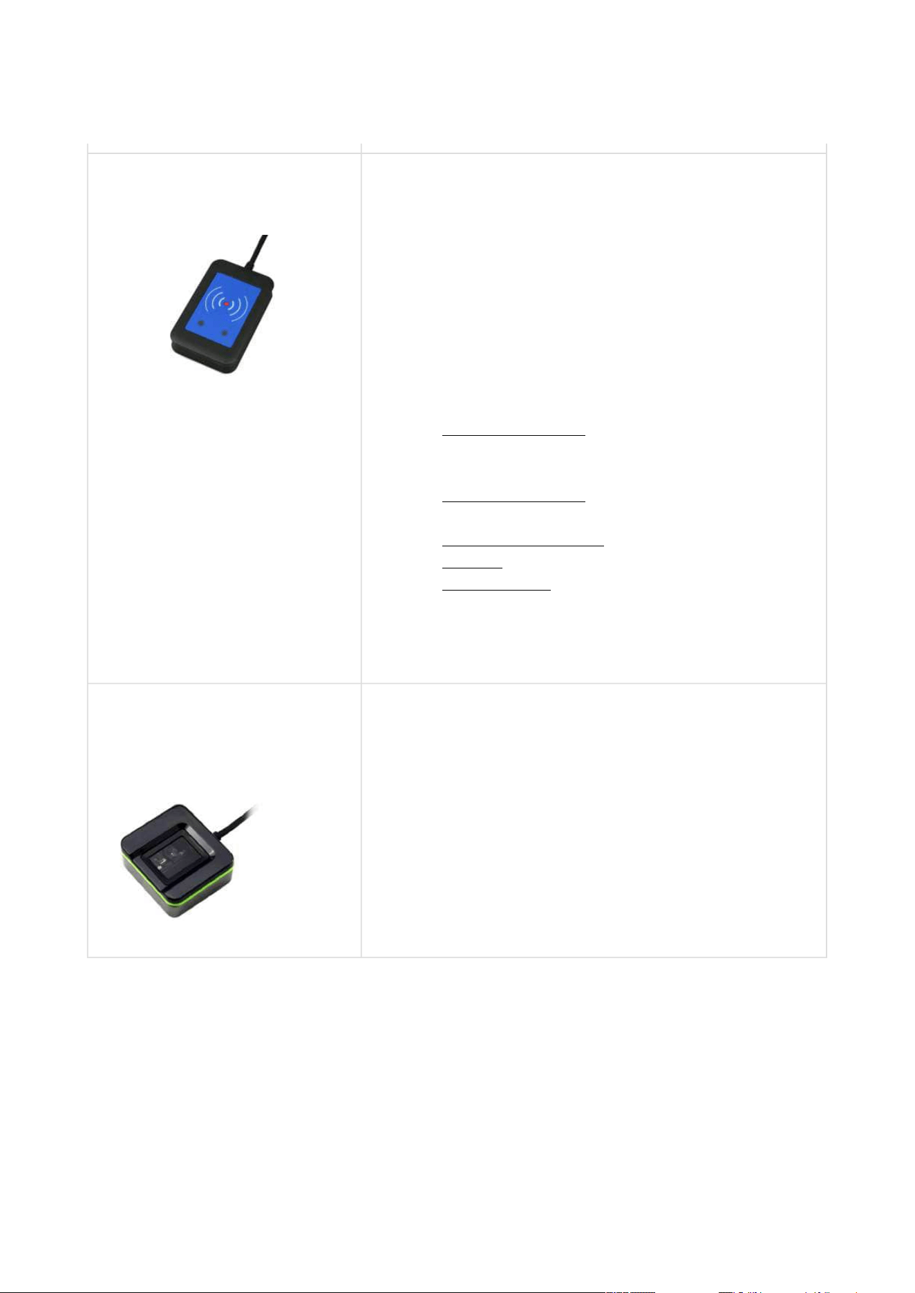
2N Part No. 9137423E
Axis Part No. 01401-001
2N IP intercom – External fingerprint reader (USB
interface)
2N Access Unit Installation Manual
33 / 118
•
•
•
•
•
•
•
•
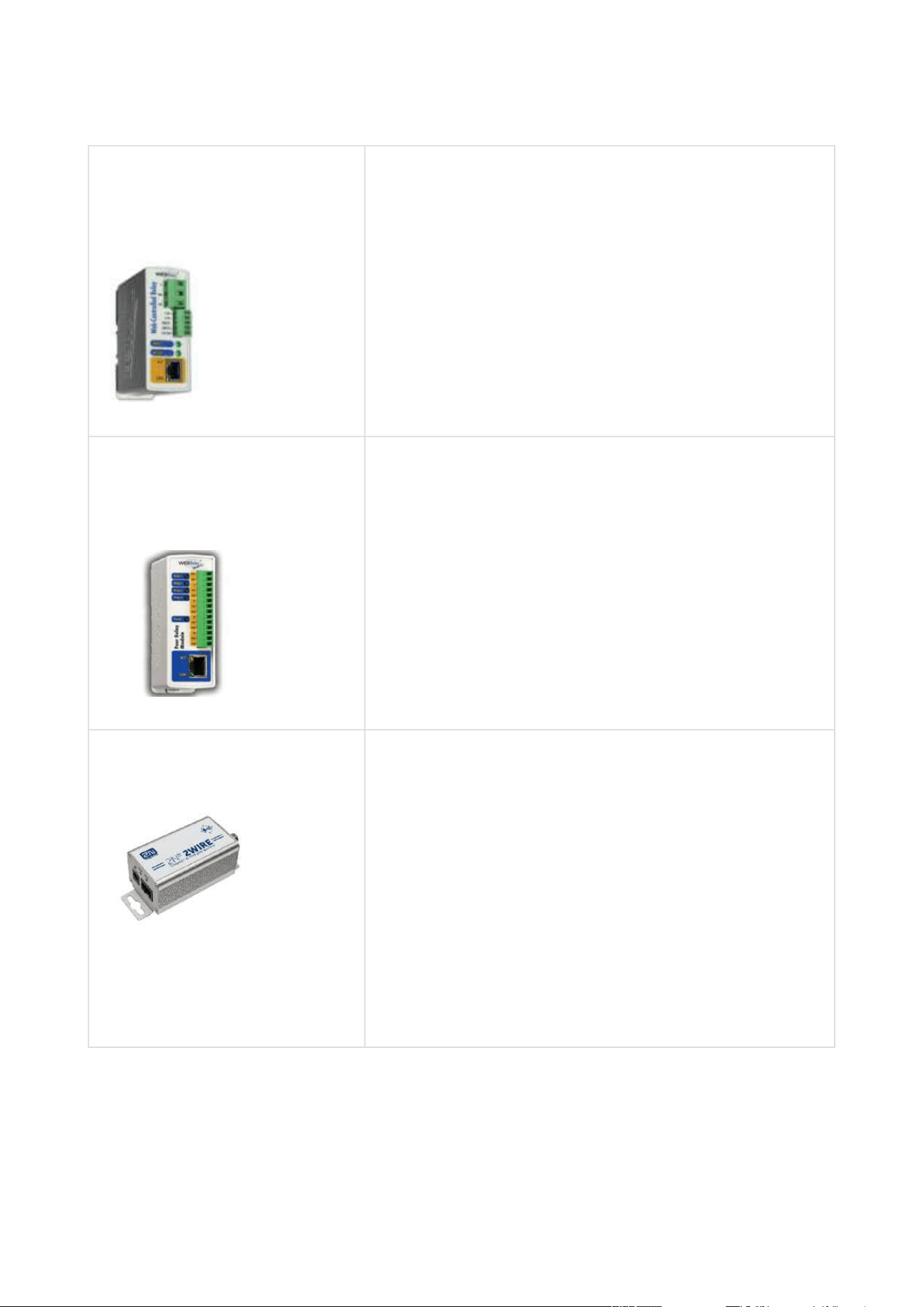
2N Part No.9137410E
Axis Part No. 01397-001
External IP relay – 1 output
A stand-alone IP device, which can be controlled from
an IP intercom viaHTTPcommands. Helps control a
device remotely.
2N Part No.9137411E
Axis Part No. 01398-001
External IP relay – 4 outputs, PoE
A stand-alone IP device, which can be controlled from
an IP intercom viaHTTP commands. Helps control a
device remotely.
Part No. 9159014EU/US/UK
2N
®
2Wire
(set of 2 adapters plus EU/US/UK power supply)
Converter 2N
®
2Wire helps you connect any IP device
to your existing two-wire cabling from the original
door bell/phone without reconfiguring. All you have to
do is have one
2N
®
2Wireunit at each end of the cable and connect
one of them at least to the power supply.
The2N
®
2Wire unitthen providesPoE supply not only
to the other converter, but also to all the IP terminal
equipment connected.
2N Access Unit Installation Manual
34 / 118
•
•
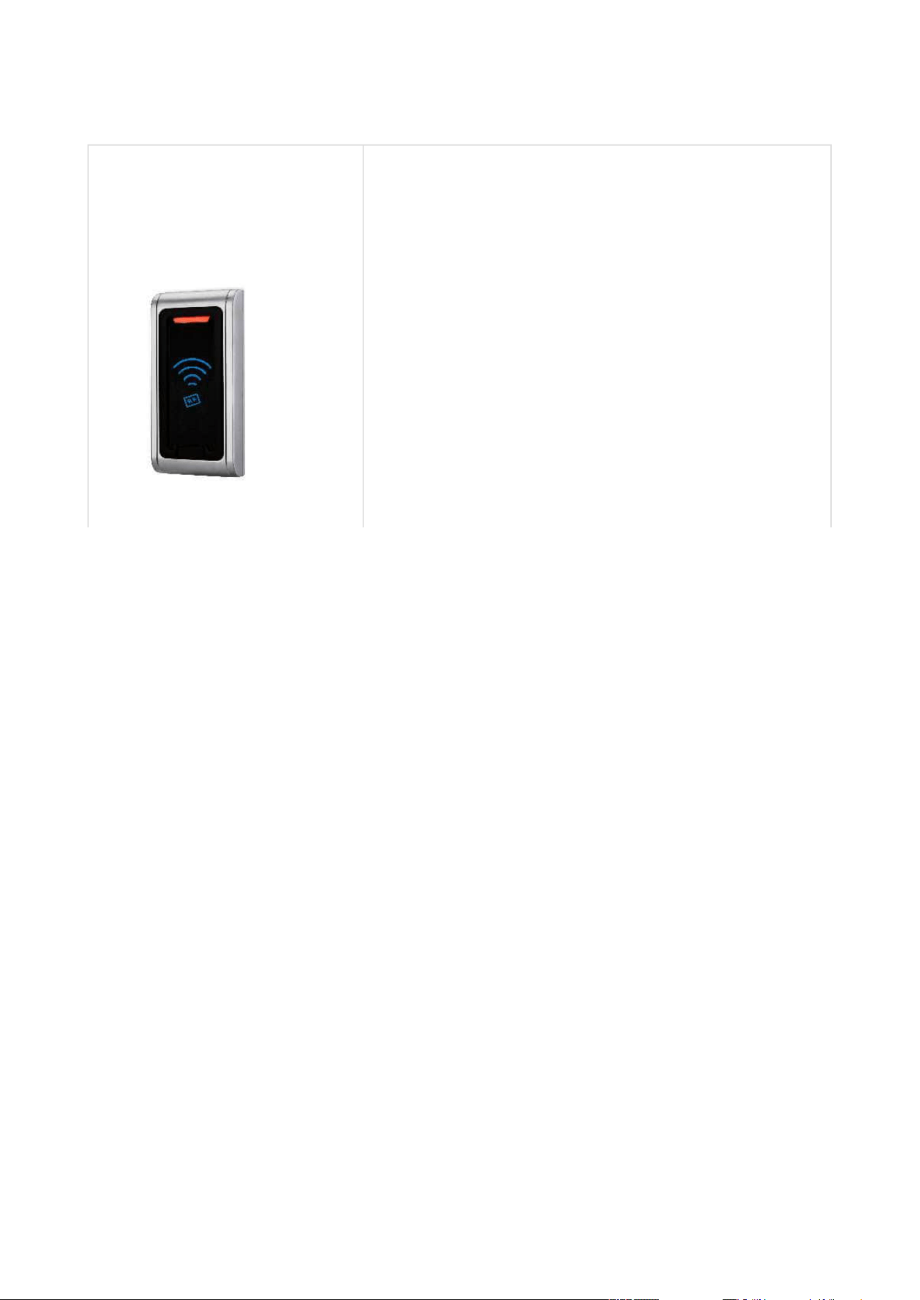
2N Part No. 9159030
Axis Part No. 01389-001
External 125 kHz RFID card reader
Secondary reader for connection to an internal reader.
Allows for control of card entry from both sides of the
door. IP67 cover, also suitable for exteriors. Reads
EM4100 and EM4102 cards.
2N Access Unit Installation Manual
35 / 118
•
•
•
•
•
•
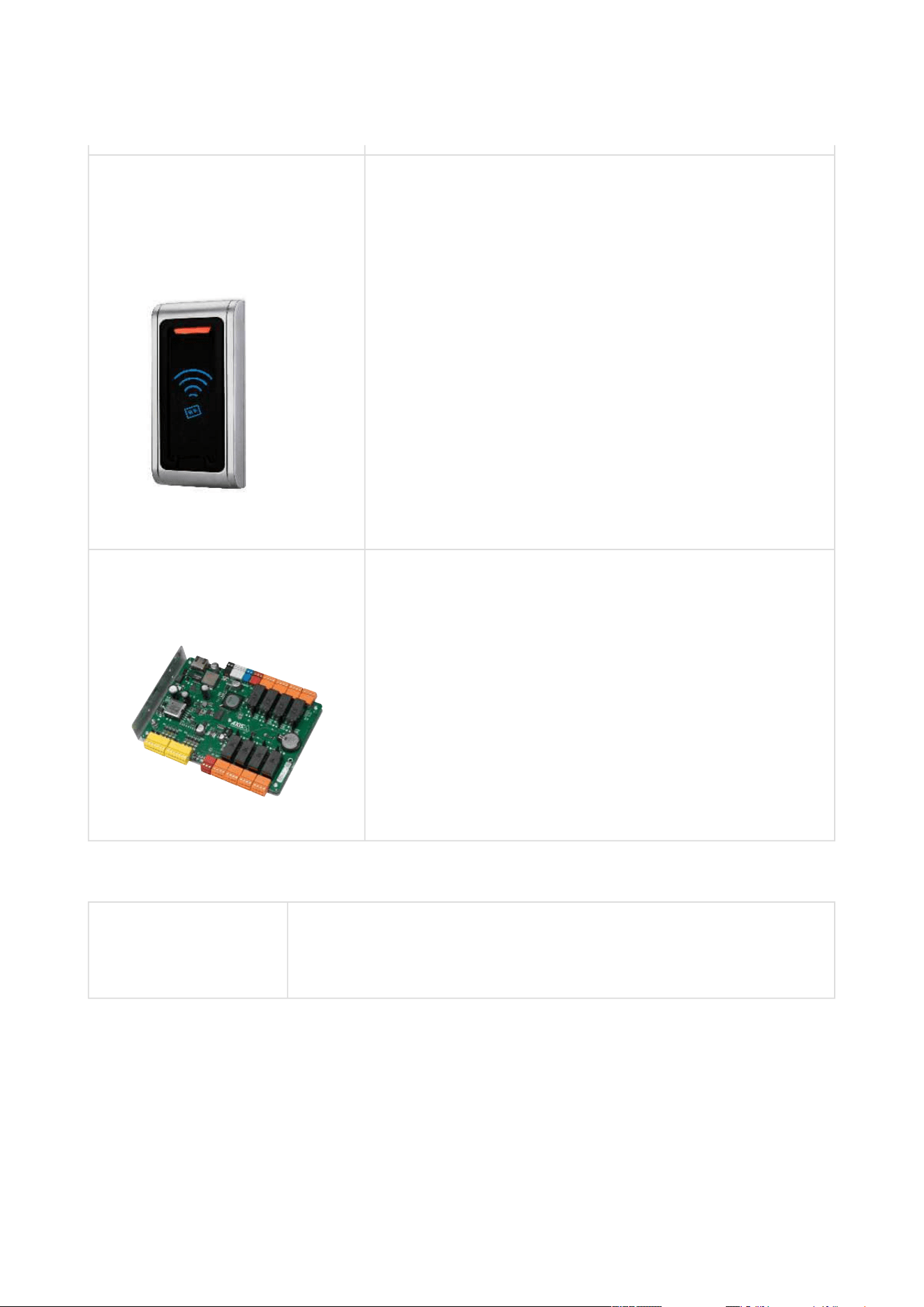
2N Part No. 9159031
Axis Part No. 01390-001
External 13.56 MHz MIFARE RFID card reader, Wiegand
Secondary reader for connection to an internal reader.
Allows for control of card entry from both sides of the
door. IP68 cover, also suitable for exteriors. Reads
MIFARE cards.
Part No.9160501
AXIS A9188 Network I/O relay module
Lift control relay module for up to 8 floors
License
Part No. 9137909
Gold
Includes Enhanced Video, Enhanced Integration and Lift Control
licenses

2N Access Unit Installation Manual
36 / 118
•
Part No. 9137910
Axis Part No.
01381-001
InformaCast
1.2 Terms and Symbols
The following symbols and pictograms are used in the manual:
•
Tip
Refer to the local 2N distributor for more accessories and recommendations
please.
•
Safety
Always abide by this information to prevent persons from injury.
•
Warning
Always abide by this information to prevent damage to the device.
•
Caution
Important informationfor system functionality.
•
Tip
Useful informationfor quick and efficient functionality.
•
Note
Routines or advice for efficient use of the device.

2N Access Unit Installation Manual
37 / 118
•
•
•
•
•
•
•
•
•
2. Description and Installation
Here is what you can find in this section:
2.1 Before You Start
2.2 Mechanical Installation
2.3 Electric Installation
2.4 Extending Module Connection
2.5 Mounting Completion
2.1 Before You Start
Product Completeness Check
Check your2NAccess Unitpackage for completeness before installation.
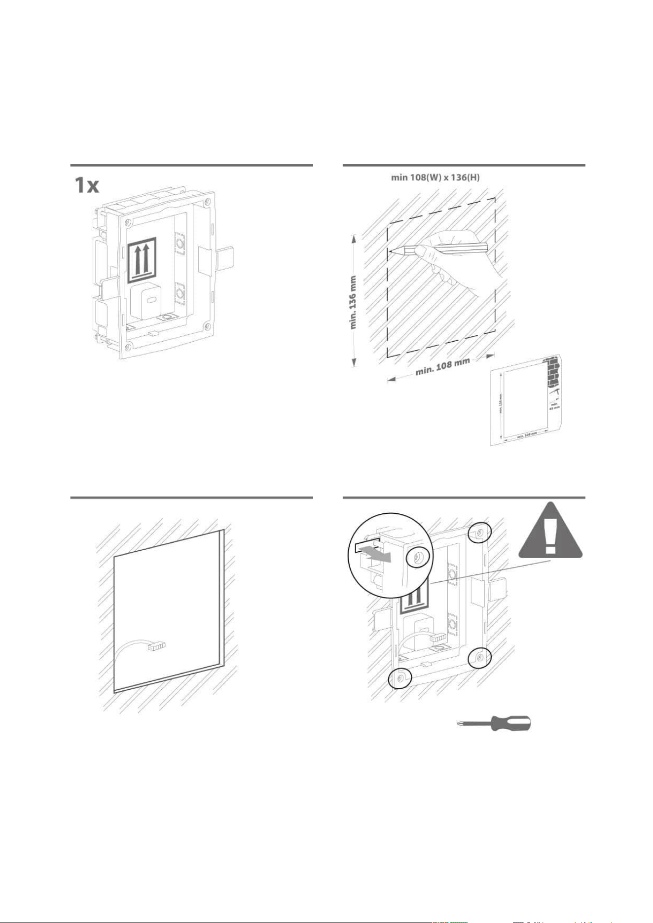
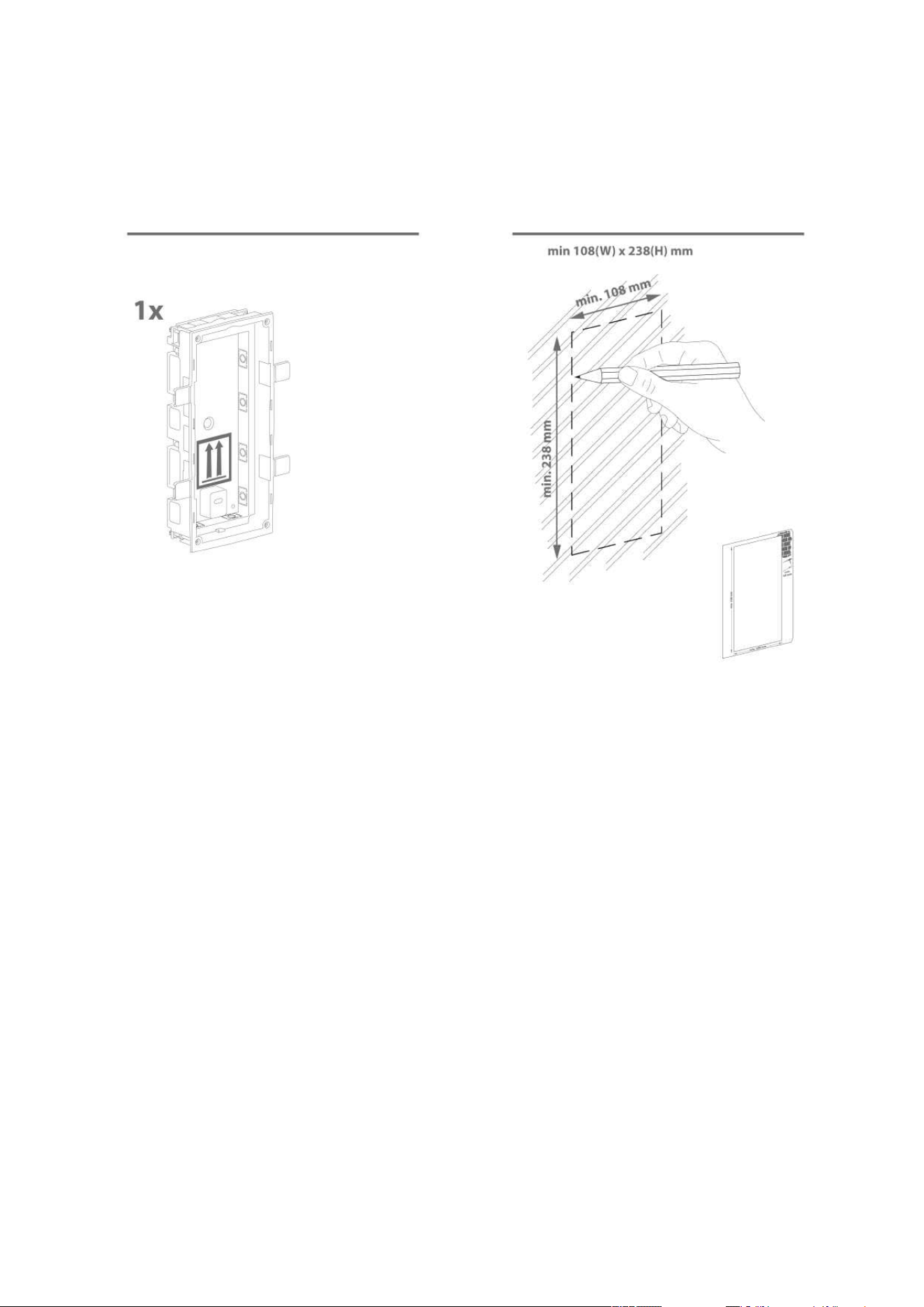
1x 2NAccess Unit
1x Hex key
1x Certificate of ownership
1x Brief manual
2.2 Mechanical Installation
Mounting Types Overview
Refer to the table below for a list of mounting types and necessary components. You can
assemble multiple units in all the mounting types.

2N Access Unit Installation Manual
38 / 118
•
•
•
•
•
•
•
•
•
•
•
•
Flush mounting – classic bricks
incl. hollow bricks, thermally insulated walls, etc.
What you need for mounting:
a properly cut hole as instructed in the box package
plaster, mounting glue, mounting foam or mortar as necessary
2N Access Unit
flush mounting box and frame
1 module: box Part No. 9155014, frame part No. 9155011
2 modules: box Part No. 9155015, frame part No.
9155012
Flush mounting – plasterboard
What you need for mounting:
a properly cut hole as instructed in the box package
2N Access Unit
flush mounting box and frame
1 module: box Part No. 9155014, frame part No. 9155011
2 modules: box Part No. 9155015, frame part No. 9155012
2N Access Unit Installation Manual
39 / 118
•
•
•
•
•
Wall (surface) mounting
(concrete and steel structures, entry barrier columns, interiors,
etc.)
What you need for mounting:
2N Access Unit
a proper frame
1 module: frame Part No. 9155021
2 modules: frame Part No. 9155022
For uneven surfaces use a backplate for the required count of
modules, Part Nos.
9155061–9155062.
•
•
•
Caution
Before starting the mechanical installation on a selected place, make sure
carefully that the preparations connected with it (drilling, wall cutting) cannot
damage the electrical, gas, water and other existing wires and pipes.
The warranty does not apply to the product defects and failures arisen as a result
of improper mounting (in contradiction herewith). The manufacturer is neither
liable for damage caused by theft within an area that is accessible after the
attached electric lock is switched on. The product is not designed as a burglar
protection device except when used in combination with a standard lock, which
has the security function.
When the proper mounting instructions are not met, water might get in and
destroy the electronics. It is because the intercom circuits are under continuous
voltage and water infiltration causes an electro-chemical reaction. The
manufacturer’s warranty shall be void for products damaged in this way!

2N Access Unit Installation Manual
40 / 118
General Mounting Principles
•
•
Tip
Select flush mounting where possible to make your product elegant looking, more
vandal resistant and more secure.
You are advised to buy the flush mounting box in advance and commission a
building company to do the masonry for you, for example. The mounting box also
helps you put your intercom exactly in the vertical position.
•
•
•
•
•
•
•
•
Caution
Make sure that the diameter of the dowel holes is accurate to avoid falling out of
the dowels! Use the mounting glue to secure the dowels if necessary.
Make sure that the depth of the dowel holes is accurate!
Do not use low-quality dowels to avoid falling out of the dowels of the wall!
Having removed the front panel, make sure that no dirt gets inside the product
(especially onto the sealing surface).
Never turn an assembly of 2N Access Unit devices after mounting. Make sure that
the flush mounting boxes have been installed accurately.
Check the plasterboard wall and room interior pressure values. If the difference
between the values is too great (as a result, e.g., of overpressure ventilation),
separate the intercom using, for example, the mounting box enclosed and seal the
cable passage.
Surface mounting may cause problems on places exposed to potential vandalism
(such as public garages, etc.). In this case, use steel anchoring elements instead of
the dowels and screws included in the delivery.
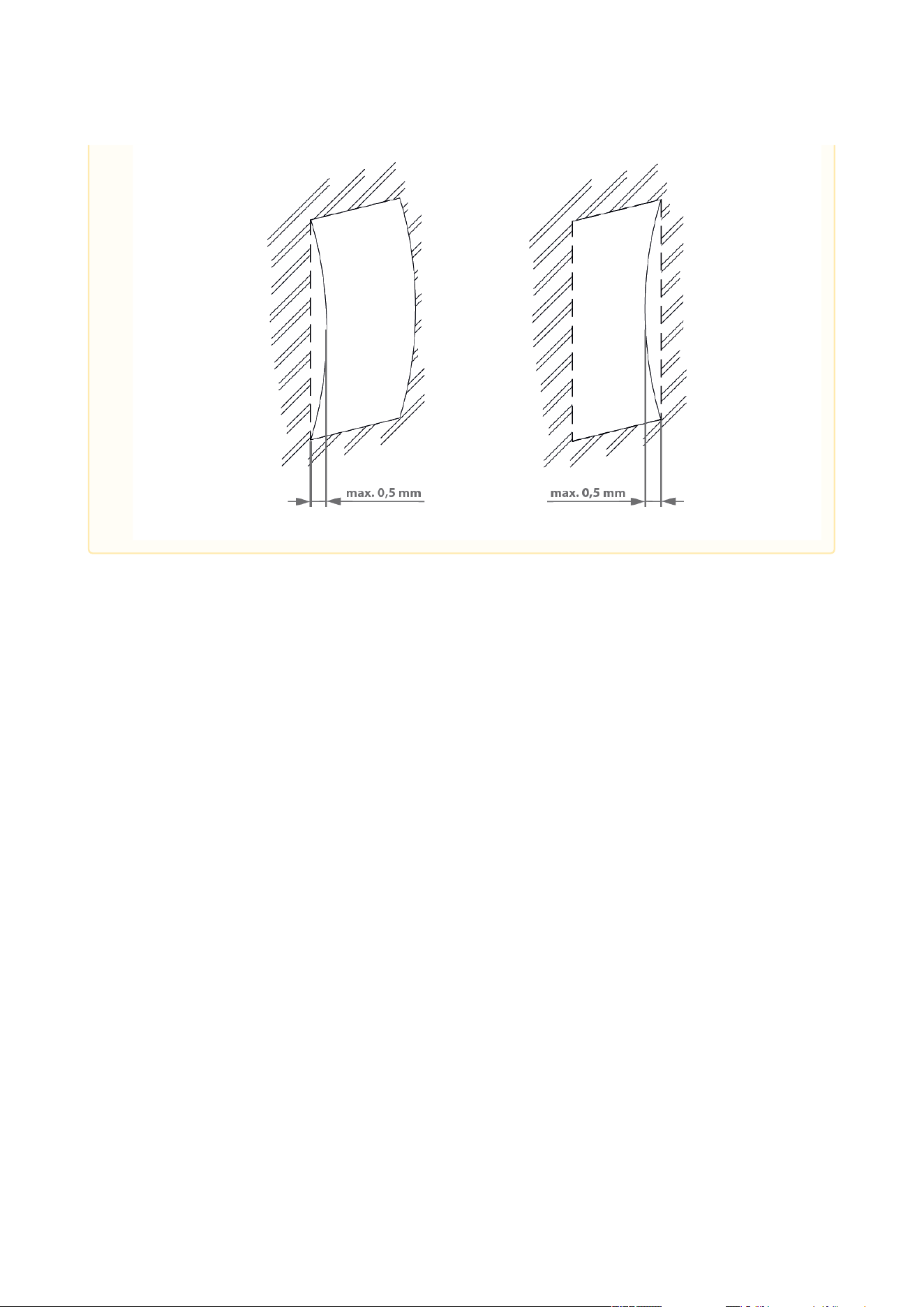
The wall mounting surface must be flat with the maximum inequality of 0.5 mm
(e.g. prefabricated boards, glass, cut stone, etc.). If the surface is uneven, use flush
mounting and a backplate, Part Nos. 9155061–9155062, or equalise the wall
surface.
2N Access Unit Installation Manual
41 / 118

2N Access Unit Installation Manual
42 / 118
•
•
•
Module Installation
2.2.1 One Module Box
2.2.2 Two Module Box
2.2.3 Module dimensions
•
Risk of personal injury
Eliminate the risk of personal injury! Wall mounting is not recommended for
narrow passages or places where people’s attention is distracted by something
else. The manufacturer shall not be liable for injuries in such cases!
2N Access Unit Installation Manual
43 / 118
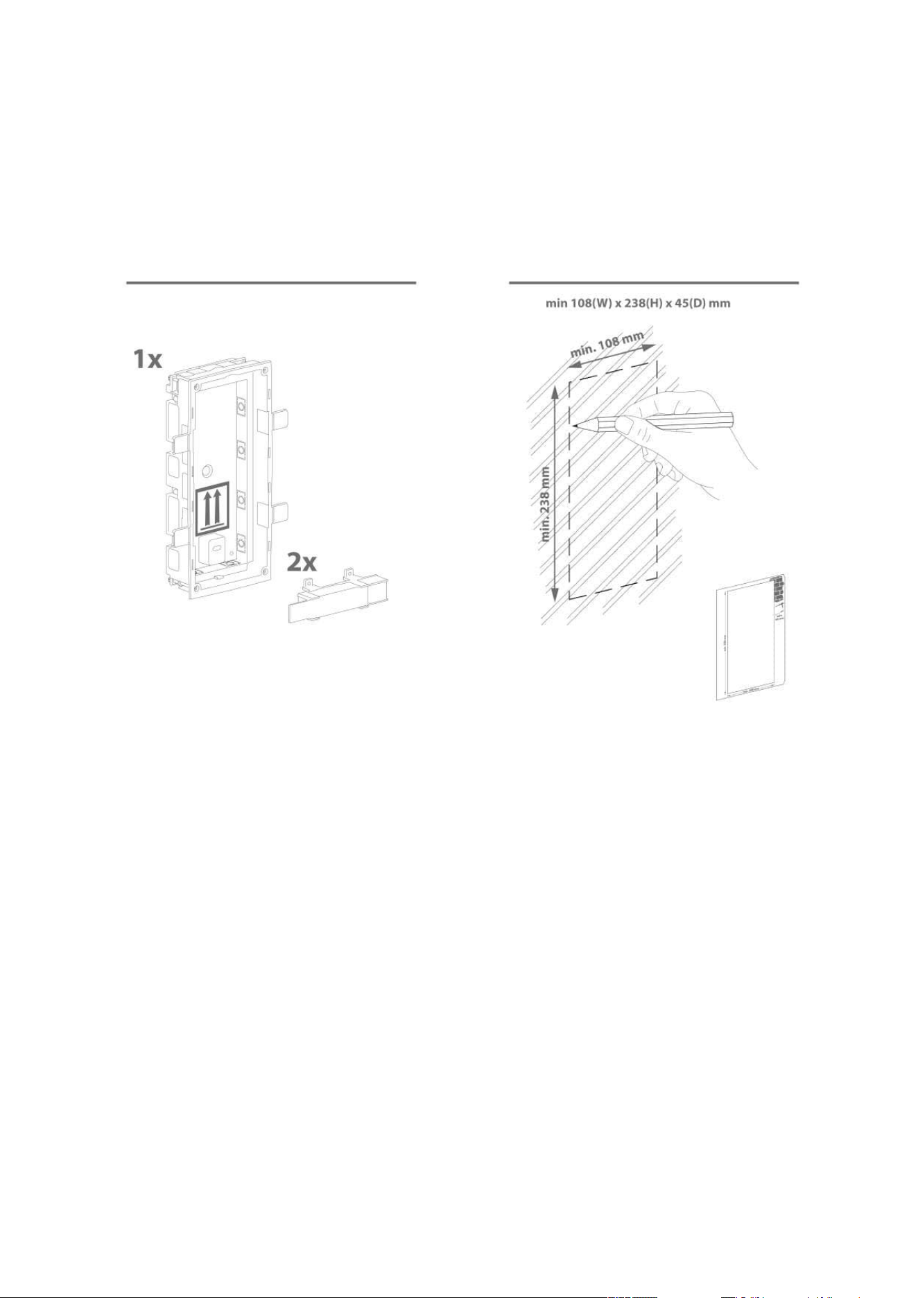
2.2.1 One Module Box
Flush mounting – classic bricks
•
Caution
The one-module box is designed for stand-alone installations of extending
modules such as departure readers. A two-module box is required for the main
unit installation.
2N Access Unit Installation Manual
44 / 118
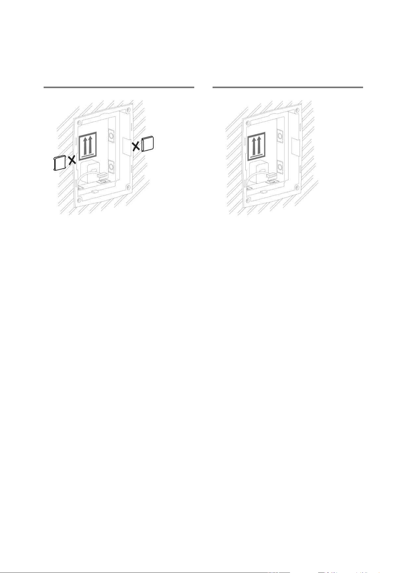
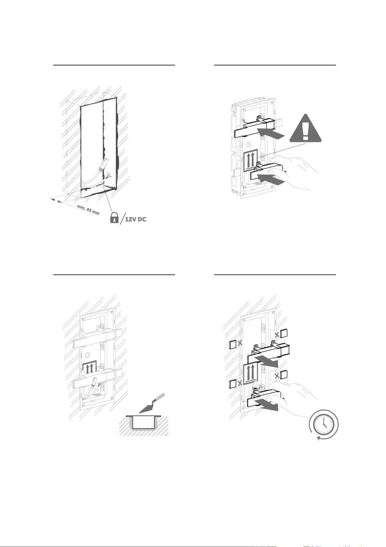
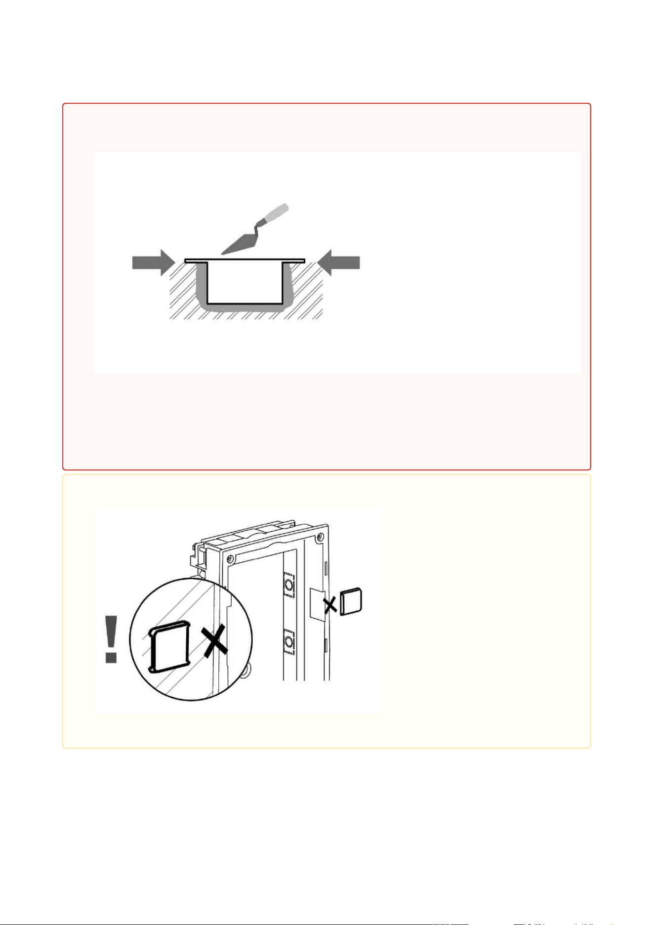
•
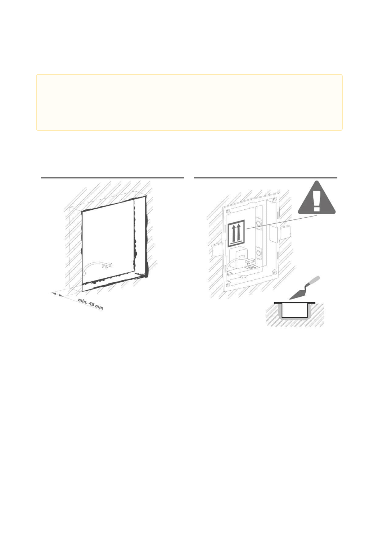
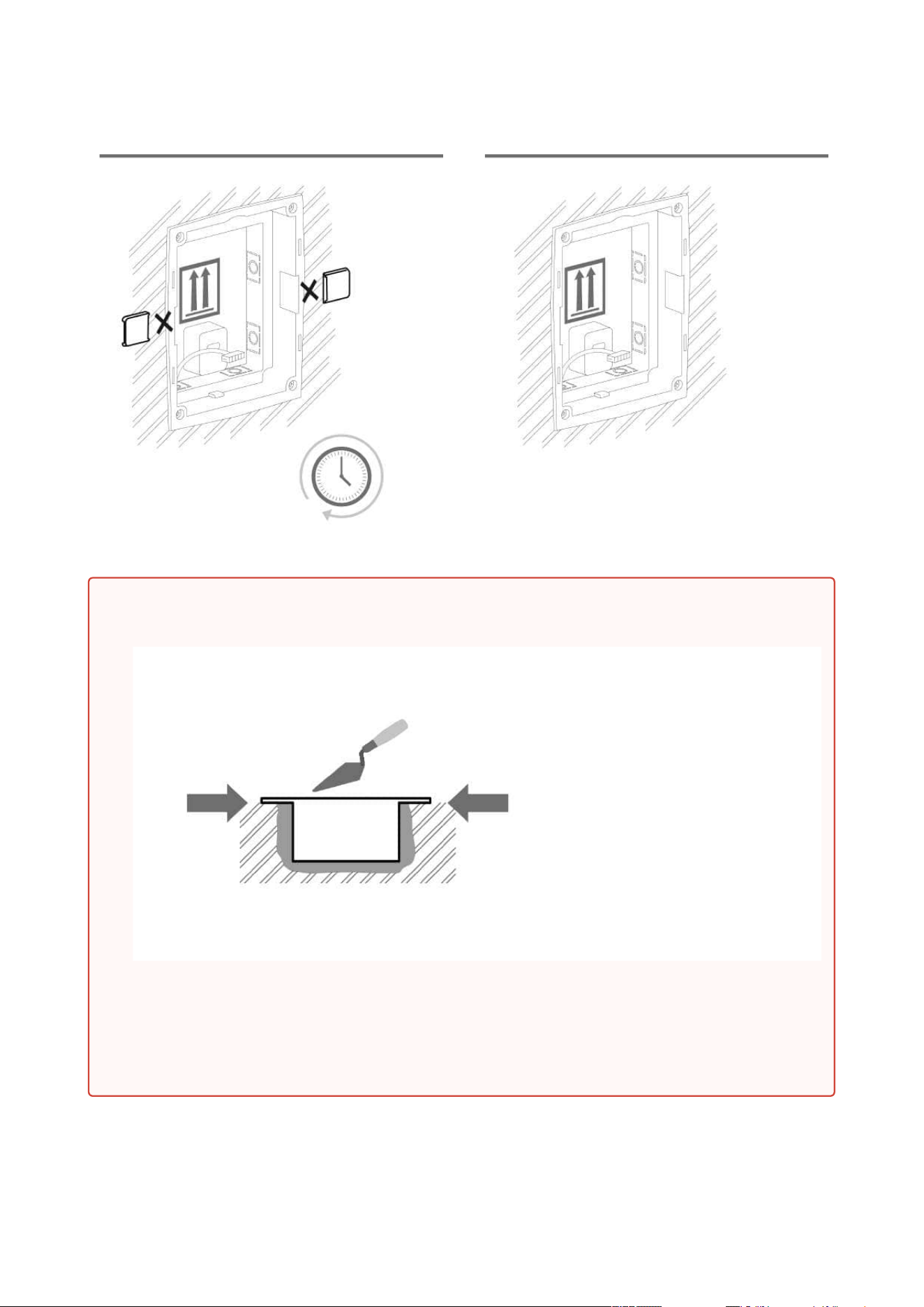
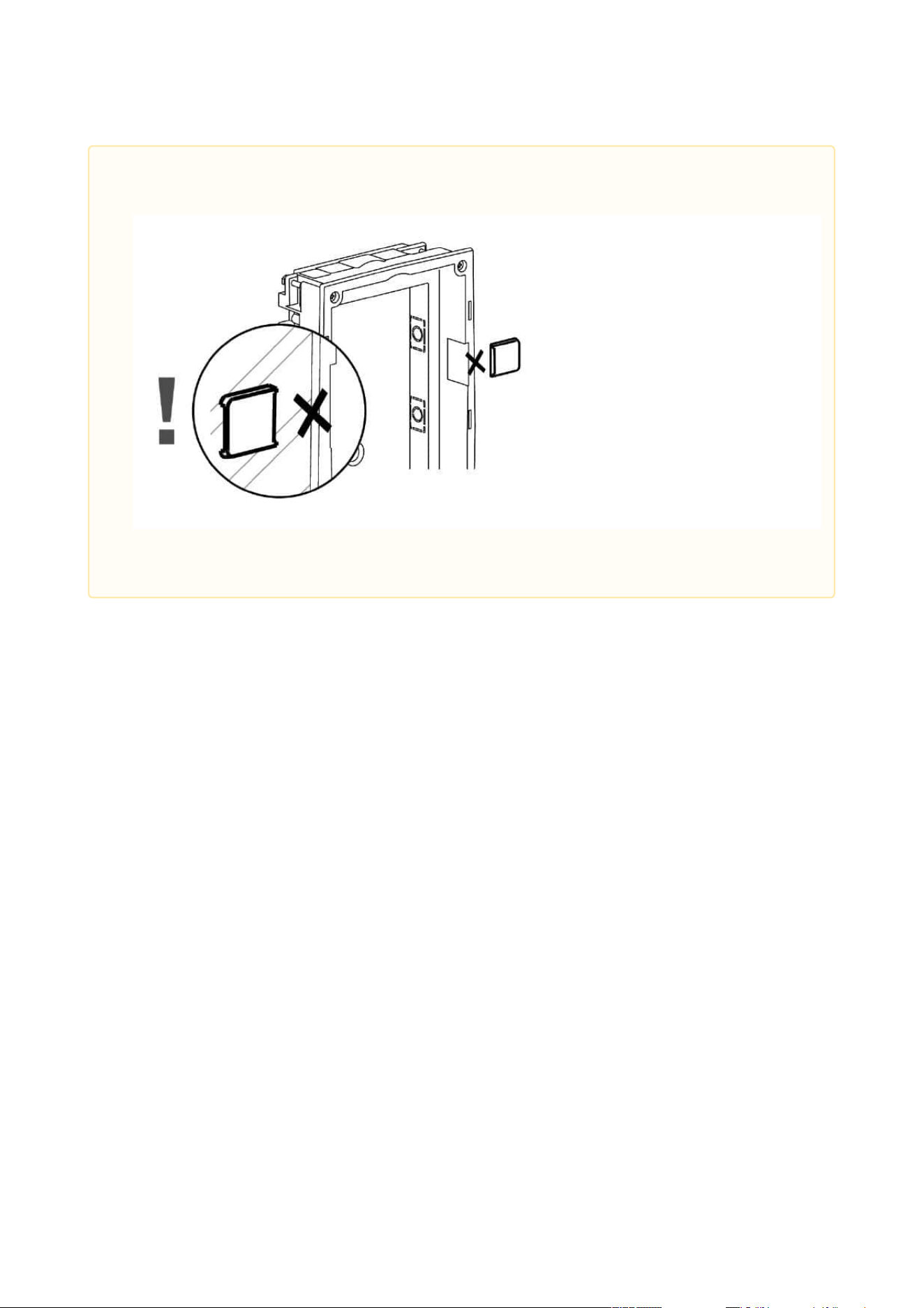
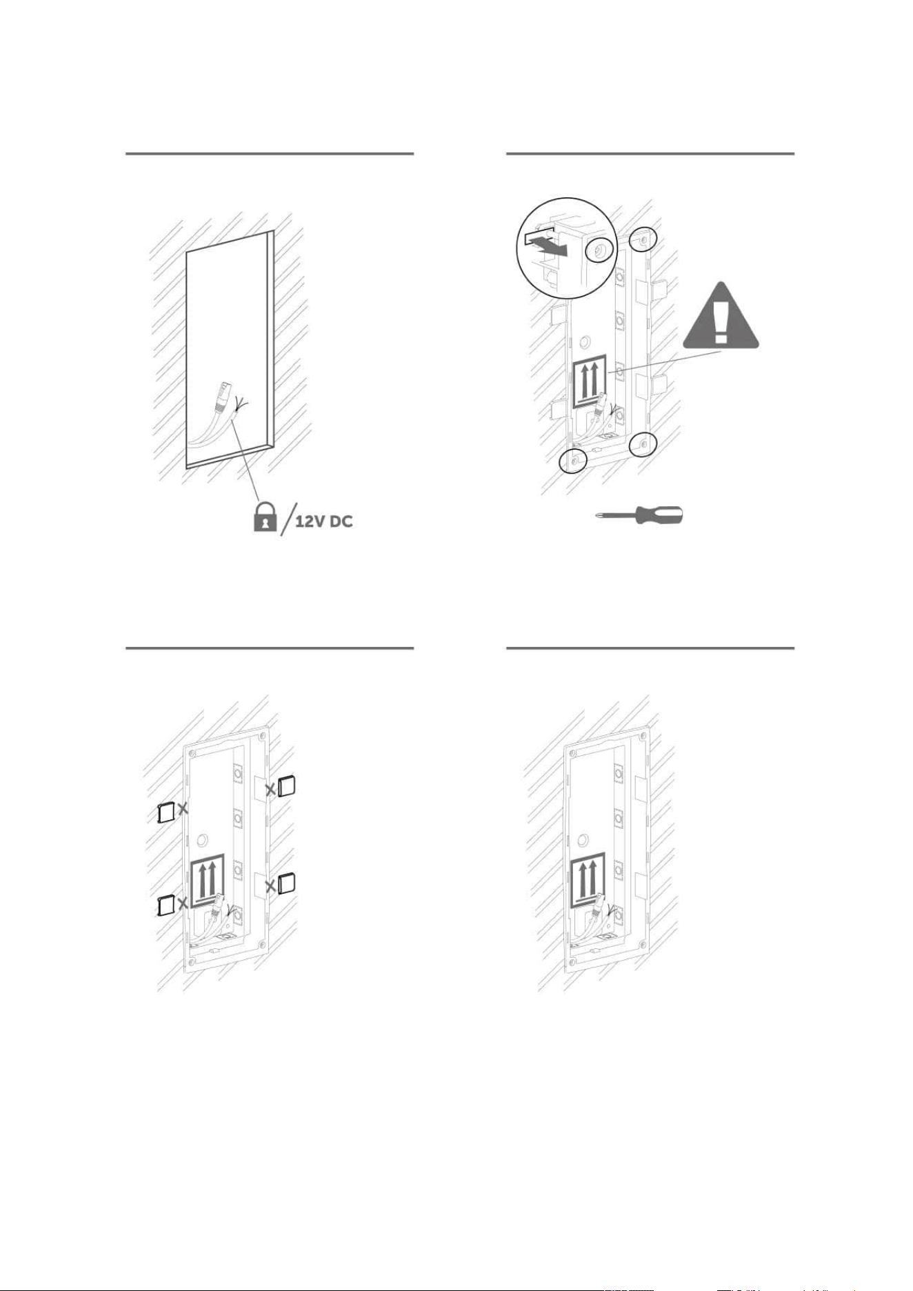
Warning
Make sure that the flush mounting box is slightly above the wall surface not
aligning with the wall. A wrong installation may lead to water penetration and
subsequent damage of the device. Use the side protrusions to achieve the proper
flush mounting.
2N Access Unit Installation Manual
45 / 118
•
Caution
Break off the side protrusions when the walling material has hardened.
2N Access Unit Installation Manual
46 / 118
Flush mounting – plasterboard
2N Access Unit Installation Manual
47 / 118
2N Access Unit Installation Manual
48 / 118
Module flush mounting
2N Access Unit Installation Manual
49 / 118
2N Access Unit Installation Manual
50 / 118
2N Access Unit Installation Manual
51 / 118
Wall (surface) mounting
2N Access Unit Installation Manual
52 / 118
2N Access Unit Installation Manual
53 / 118
2N Access Unit Installation Manual
54 / 118
2N Access Unit Installation Manual
55 / 118
2.2.2 Two Module Box
Flush mounting – classic bricks
2N Access Unit Installation Manual
56 / 118

2N Access Unit Installation Manual
57 / 118
2N Access Unit Installation Manual
58 / 118
•
Warning
Make sure that the flush mounting box is slightly above the wall surface not
aligning with the wall. A wrong installation may lead to water penetration and
subsequent damage of the device. Use the side protrusions to achieve the proper
flush mounting.
•
Caution
Break off the side protrusions when the walling material has hardened.
2N Access Unit Installation Manual
59 / 118
Flush mounting – plasterboard
2N Access Unit Installation Manual
60 / 118
2N Access Unit Installation Manual
61 / 118
Module flush mounting
2N Access Unit Installation Manual
62 / 118
2N Access Unit Installation Manual
63 / 118
2N Access Unit Installation Manual
64 / 118
2N Access Unit Installation Manual
65 / 118
Wall (surface) mounting
2N Access Unit Installation Manual
66 / 118
2N Access Unit Installation Manual
67 / 118
2N Access Unit Installation Manual
68 / 118
•
•
•
•
•
•
2.2.3 Module dimensions
Frames
9155011– Flush mounting frame, 1 module
9155012– Flush mounting frame, 2 modules
9155021– Surface mounting frame, 1 module
9155022– Surface mounting frame, 2 modules
Backplates
9155061– 1 module
9155062– 2 modules
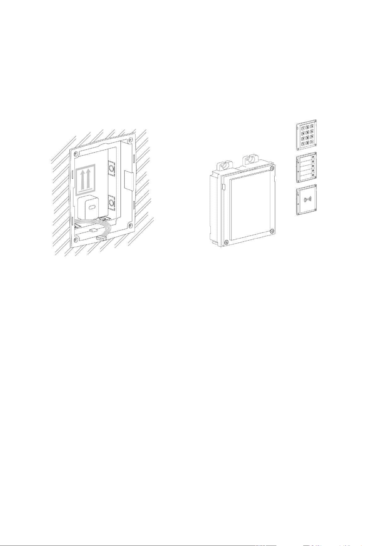
2.3 Electric Installation
This subsection describes how to install the modules and connect the2NAccess Unitto the
power supply and LAN and how to connect other elements.

2N Access Unit Installation Manual
69 / 118
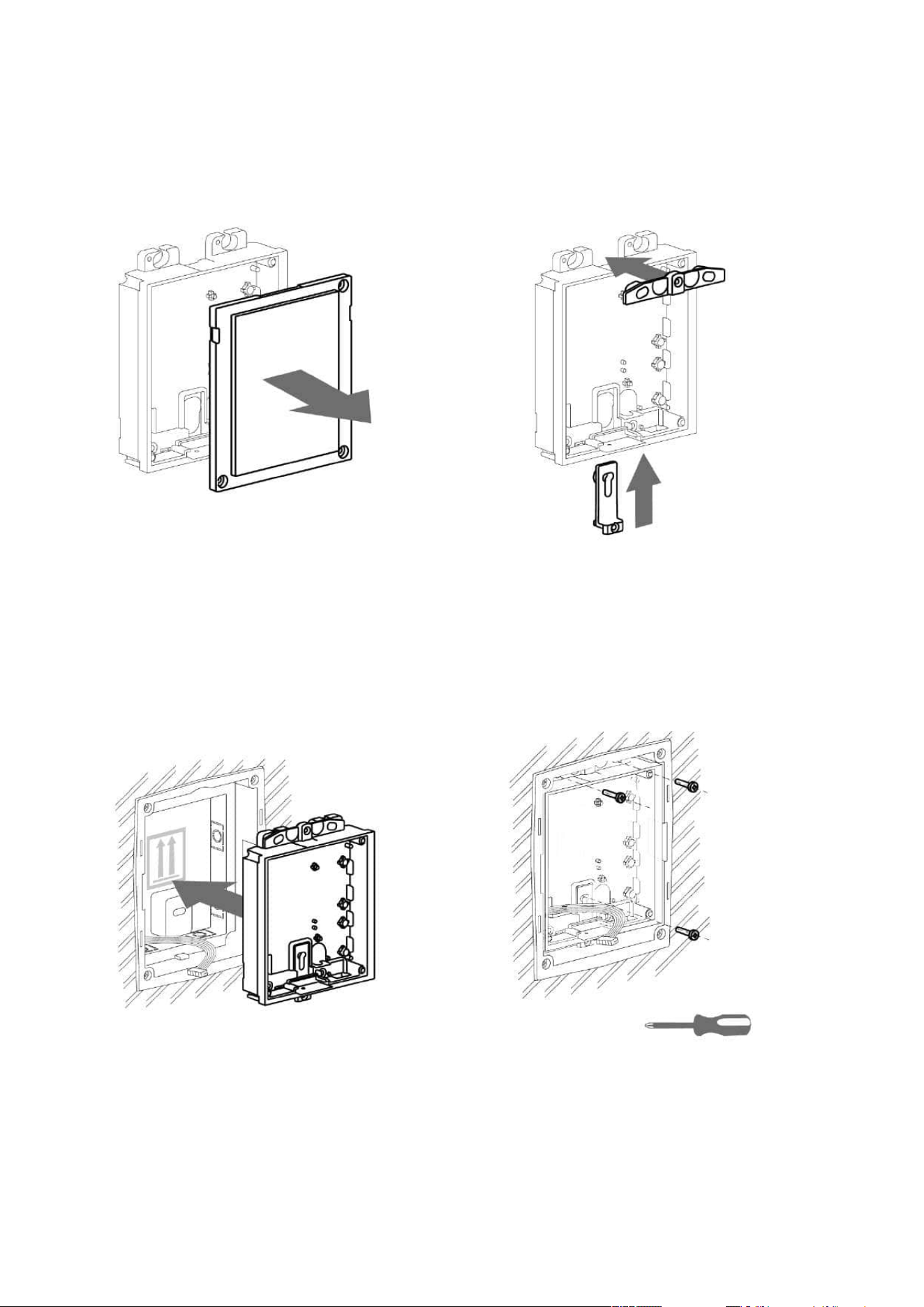
1.
2.
1.
2.
3.
4.
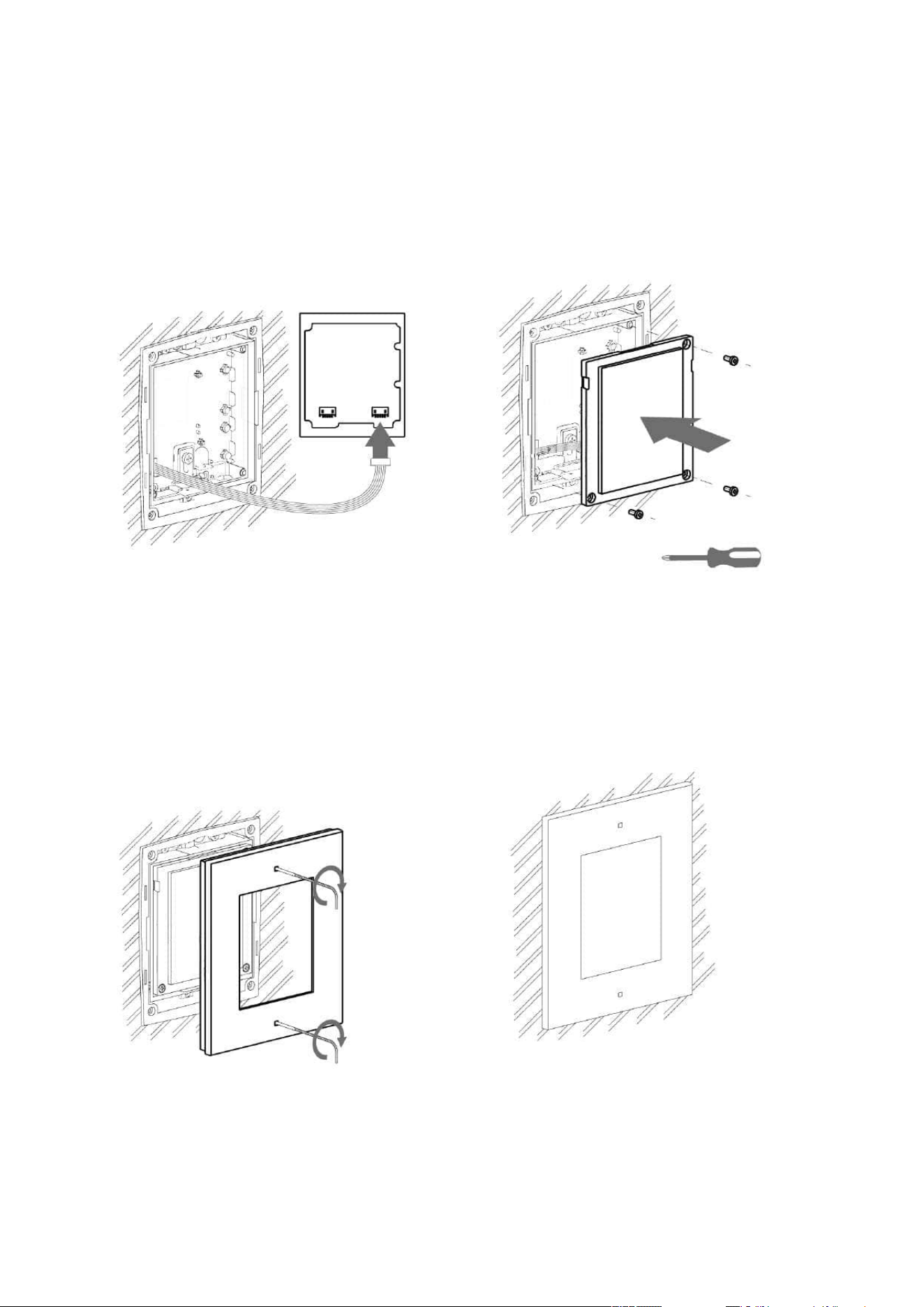
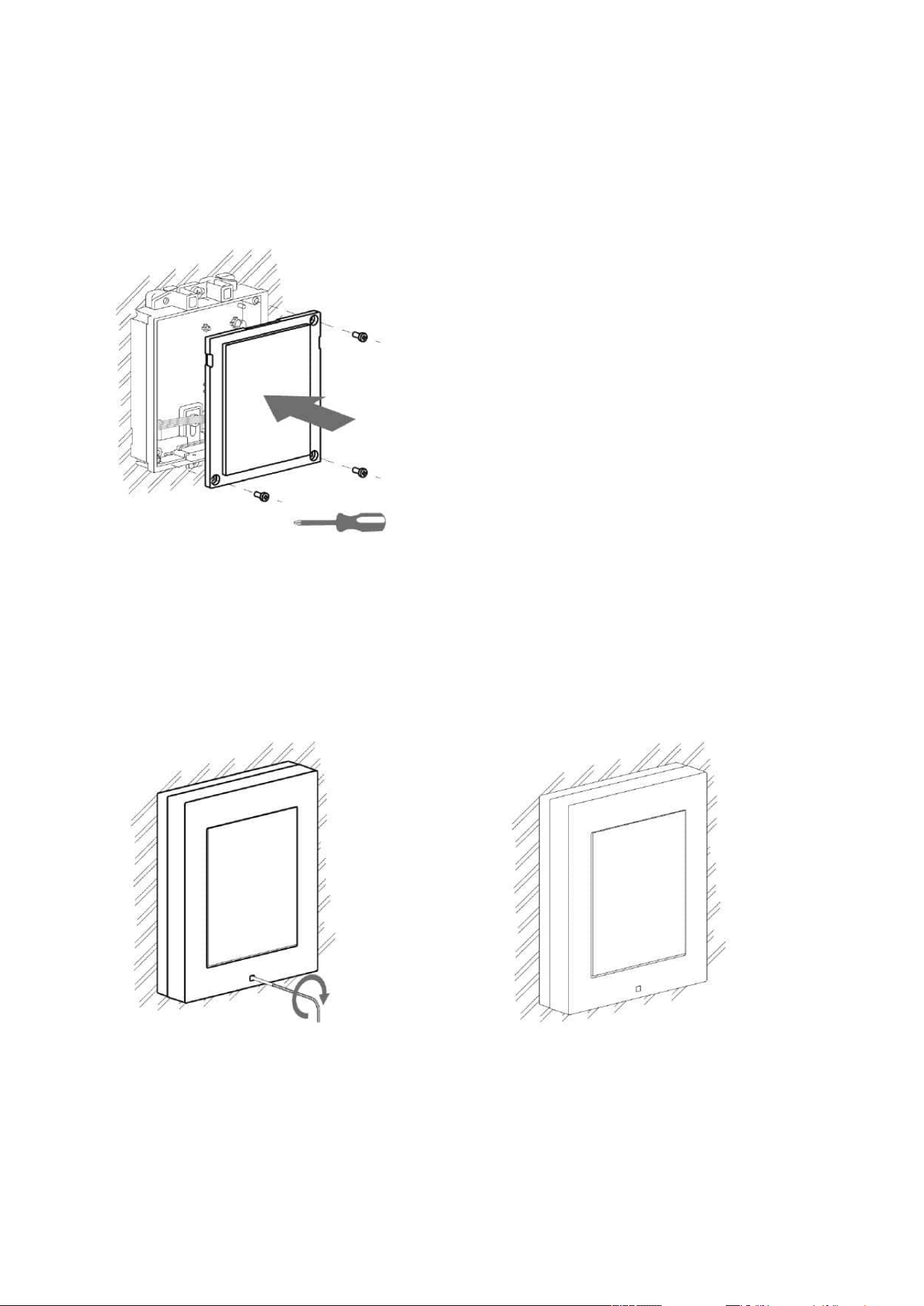
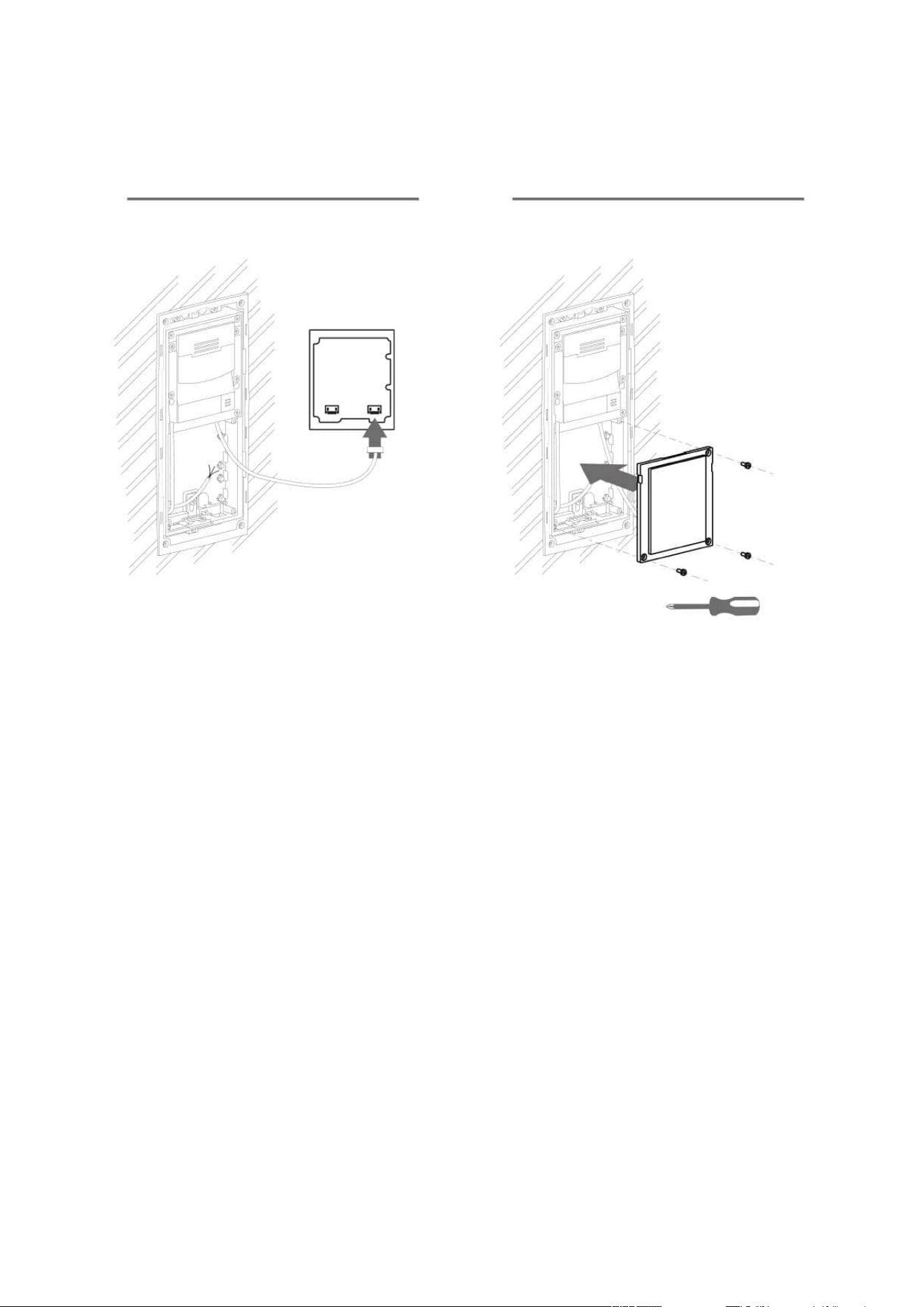
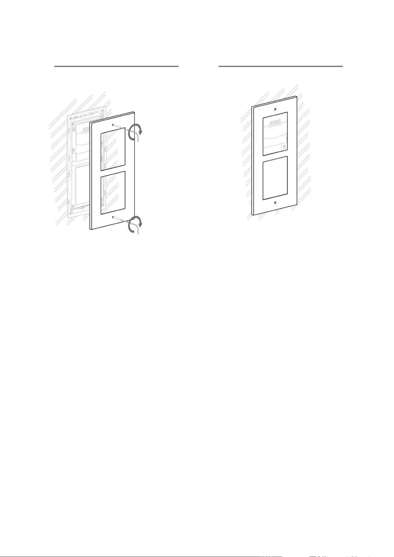
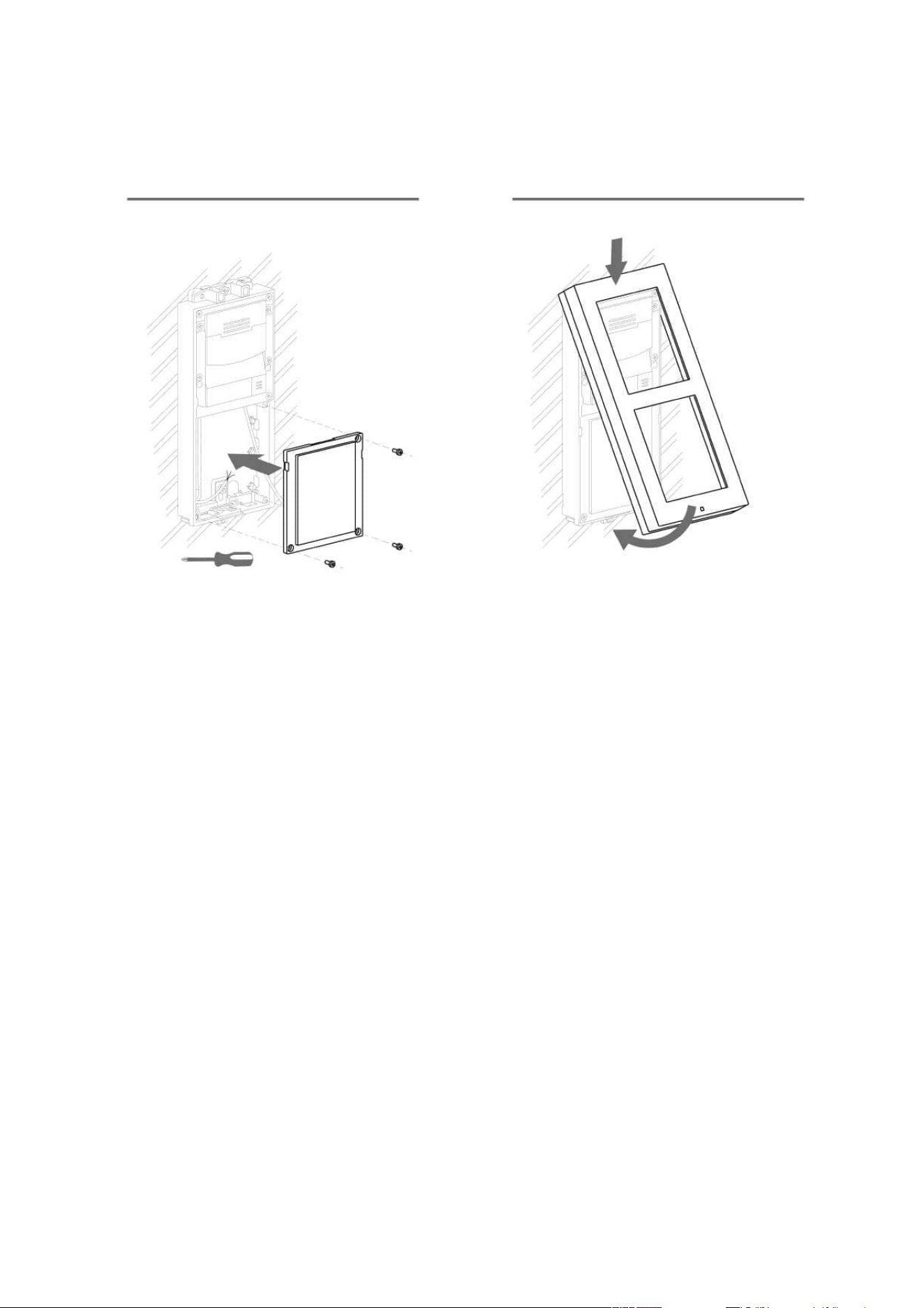
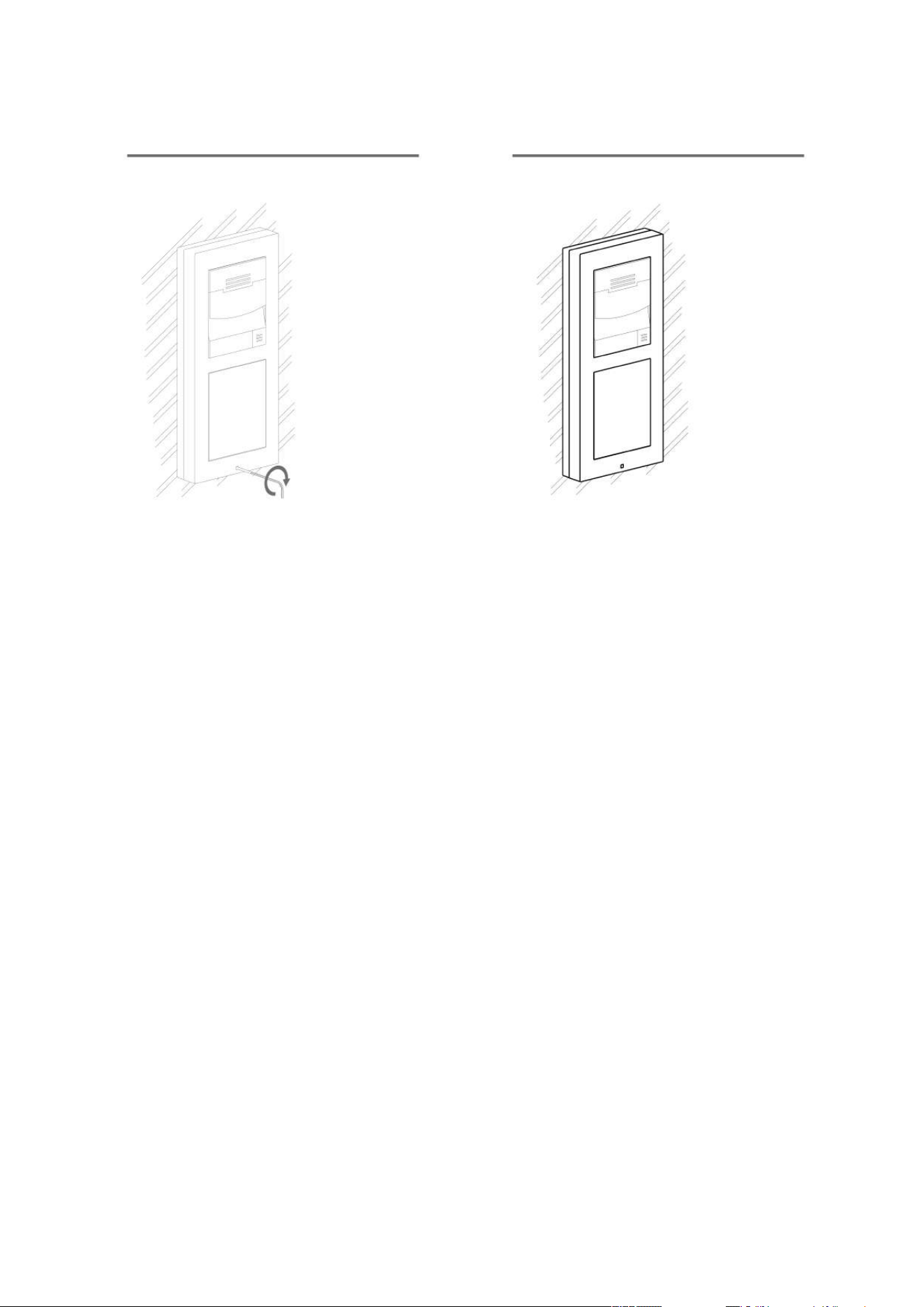
Version A – Stand-alone Access Unit
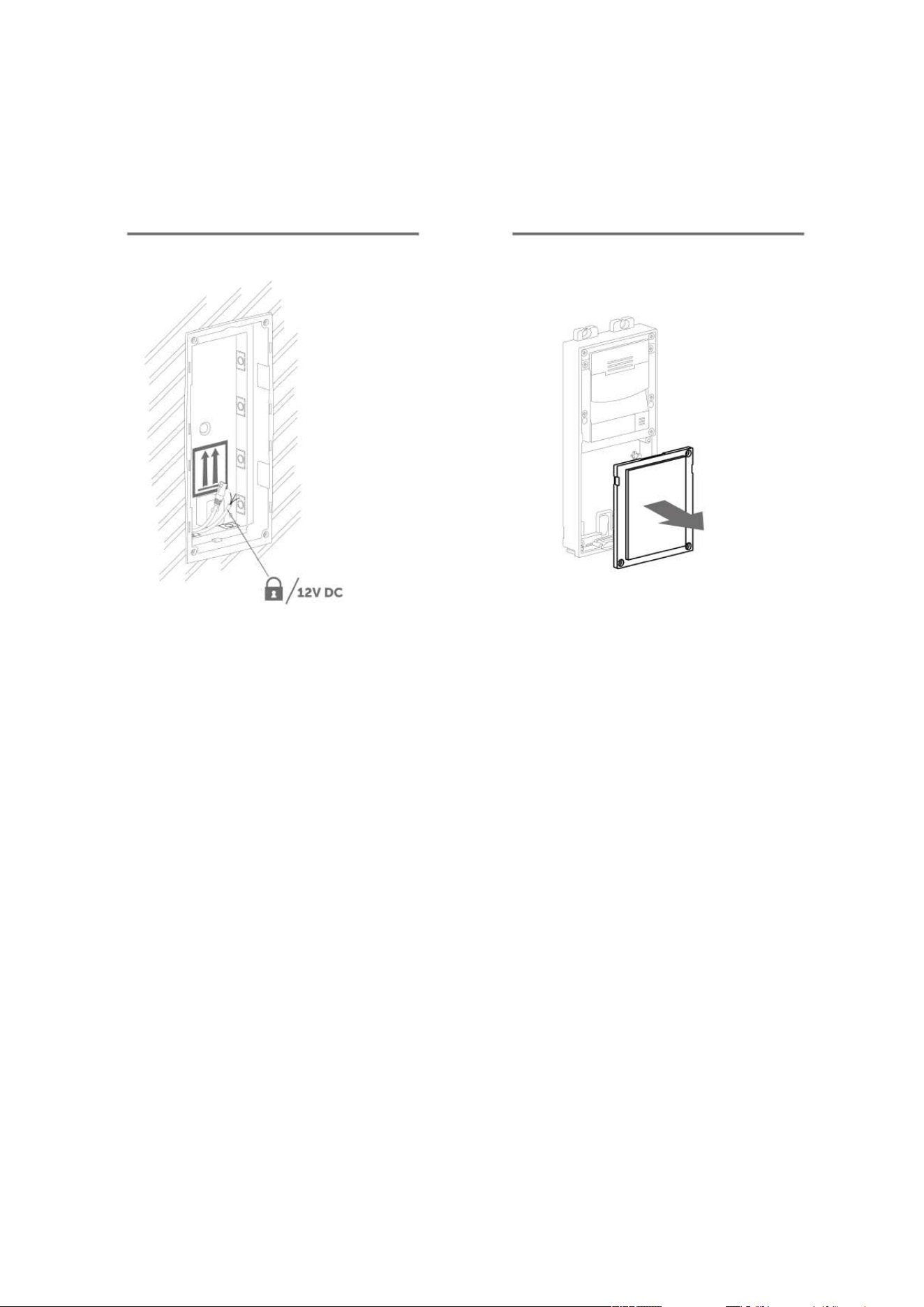
Place the2NAccess Uniton the flush mounting box / pre-drilled holes with dowels and
pull the cables through the bottom holes. Pull the Ethernet cable through the bottom hole
to the left if necessary.
Insert the metal fitting elements up and down and screw the access unit tight. You can
level the unit slightly in this mounting type.
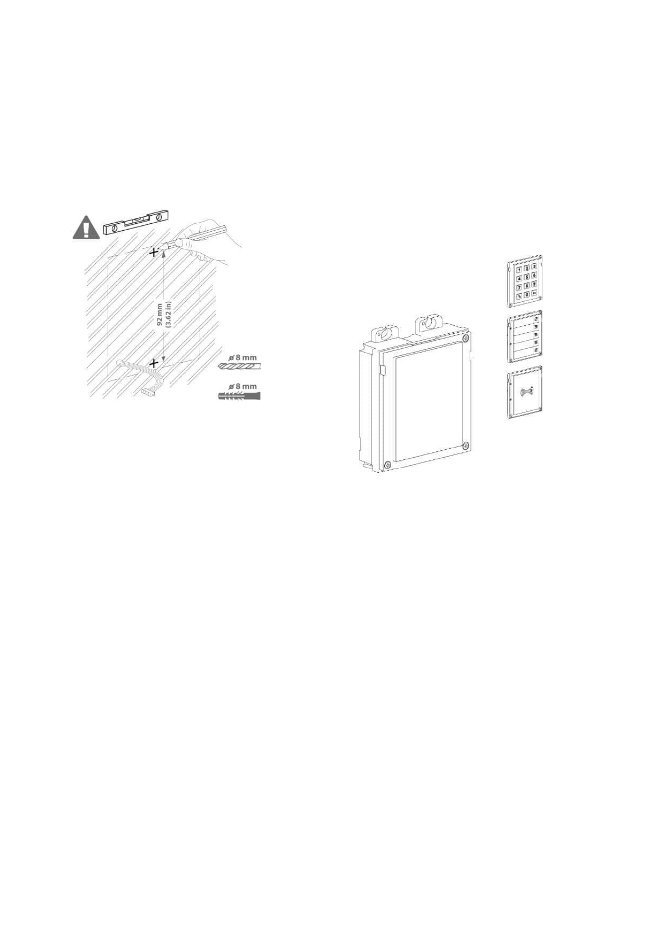
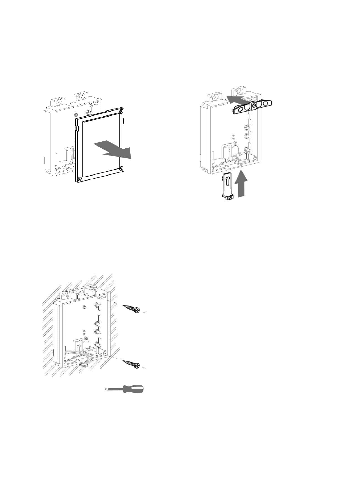
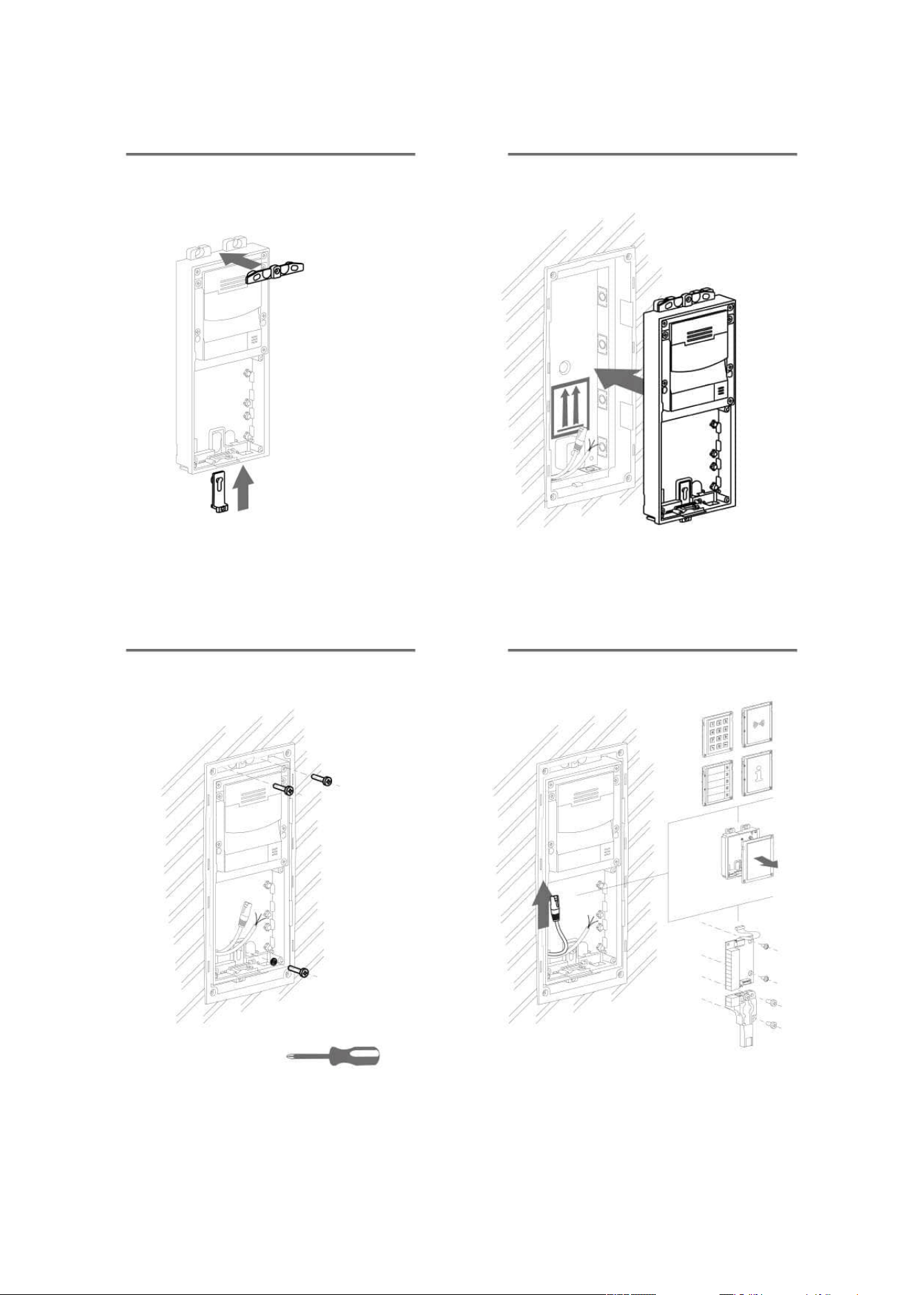
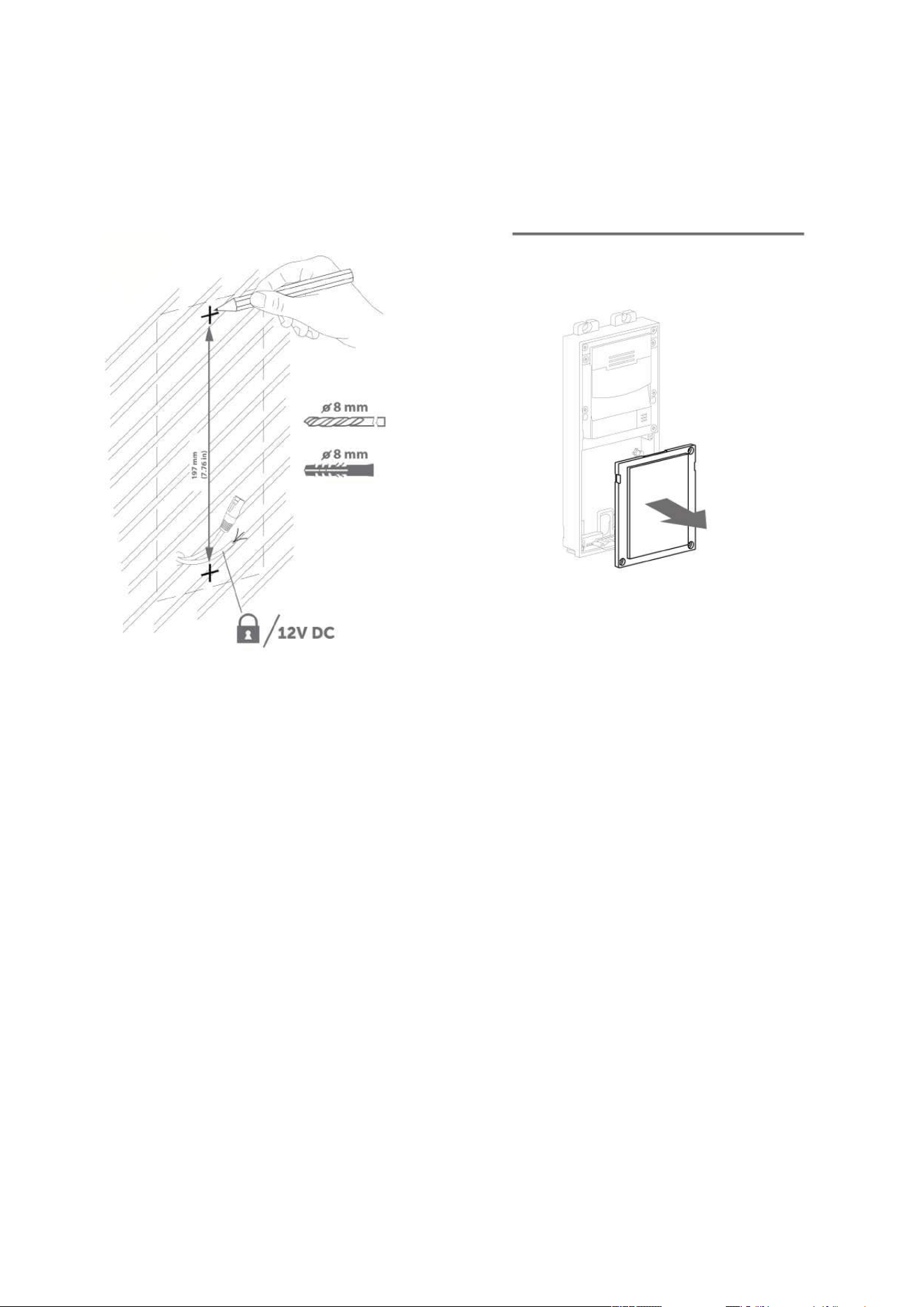
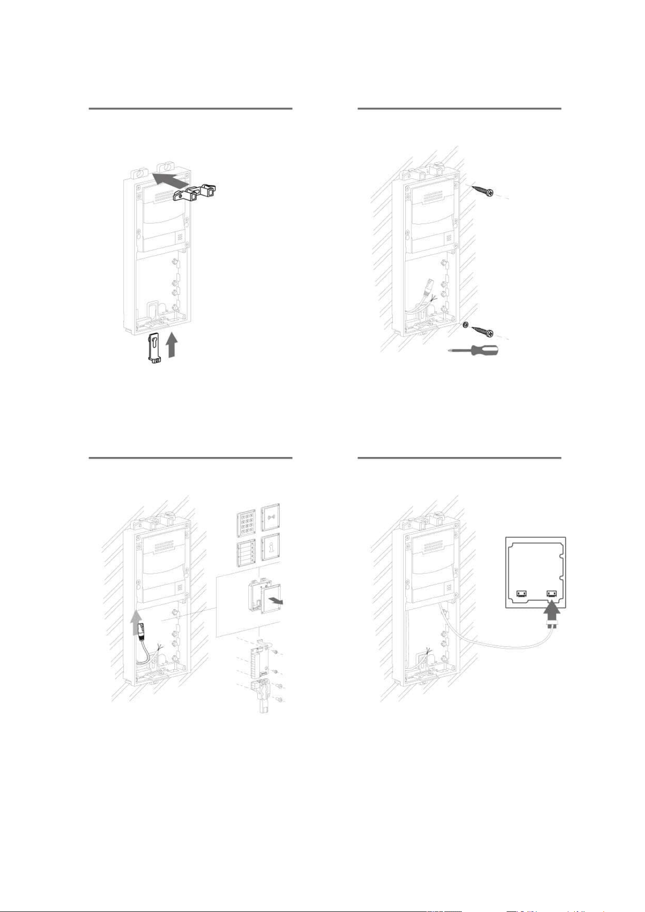
Version B – Access Unit with additional module
Unscrew the upper part of the additional base – keypad, RFID reader, etc.
Use a flat screwdriver to take the upper part out.
Slide the additional module to the access unit. Secure its position with small side wedges
and screws.
Place the assembled modules on the flush mounting box / predrilled holes with dowels
and pull the cables through the access unit bottom holes. Feed the Ethernet cable without
the connector from the additional module to the access unit base if necessary.
2NAccess Unit
Power Supply Connection
2NAccess Unitcan be powered either from an external 12 V / 1 A DC source or directly from the
LAN equipped with PoE 802.3af supporting network elements.
External power supply
For reliability reasons, use a 12 V ±15 % SELV supply dimensioned to the current consumption as
required for feeding of the access unit and connected modules.
Current consumption
[A]
Part No. Available power output
[W]
1 91341482E, 91341482US 12
•
Warning
With 2N Access Unit 2.0, modules can be exchanged arbitrarily within a unit. With
earlier versions (2N Access Unit 1.0), however, the whole unit must be replaced.

2N Access Unit Installation Manual
70 / 118
PoE power supply
2NAccess Unitis compatible with PoE 802.3af (Class 0–12.95 W) and can be fed directly from
the LAN via the compatible network elements. If your LAN does not support this technology,
insert a PoE injector, Part No. 91378100, between 2NAccess Unitand the nearest network
element. This power supply provides2NAccess Unitwith 12 W for feeding of itself and the
connected modules.
Combined power supply
2NAccess Unitcan be fed from an external power supply and PoE at the same time. In this
configuration, the maximum power for the connected modules is available.
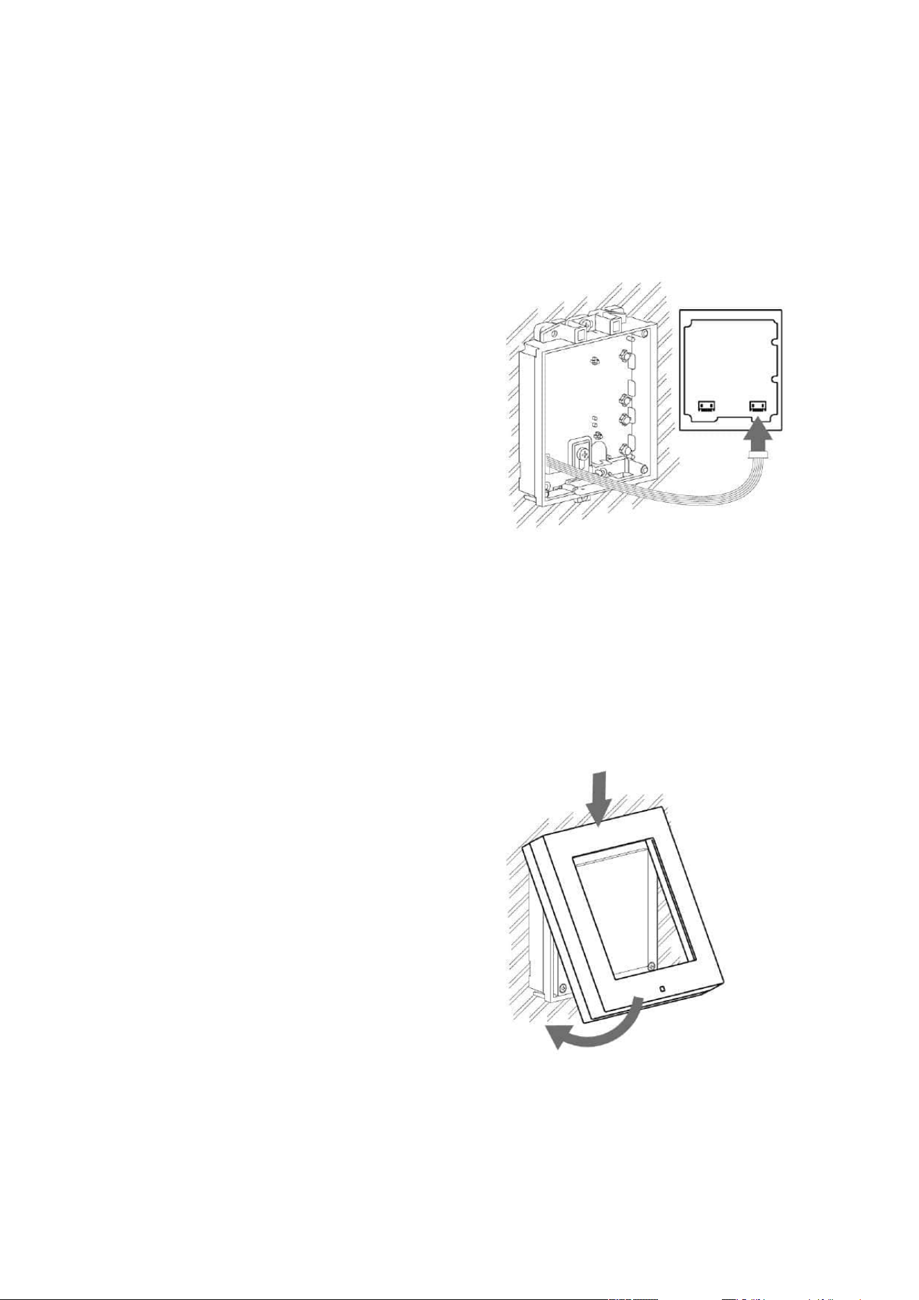
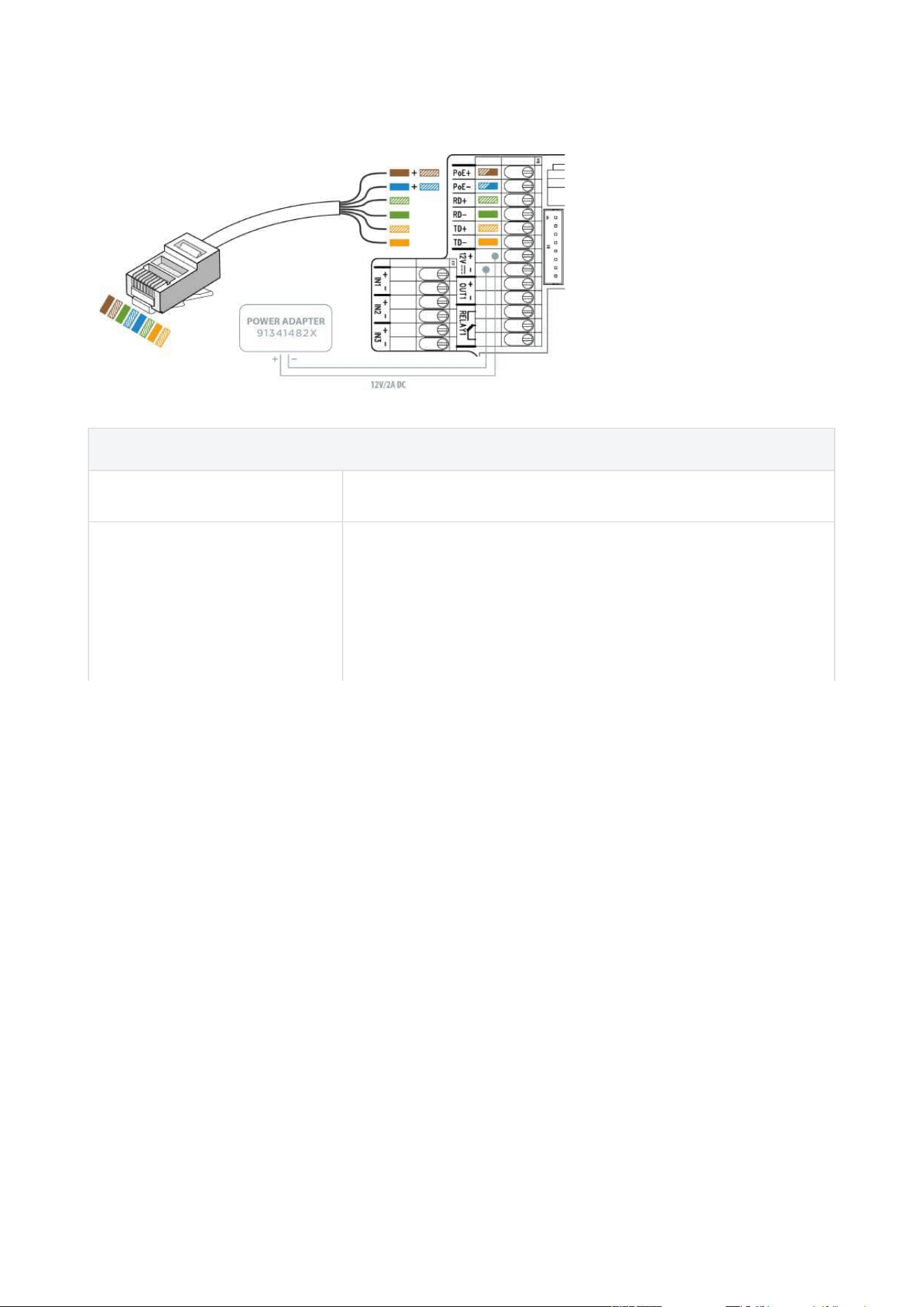
LAN Connection
2NAccess Unitis connected to the Local Area Network (LAN) via the UTP/STP cable (Cat 5e or
higher) terminated with a terminal board as shown in the figure below. As the device is equipped
with the Auto-MDIX function, either the straight or crossed cable can be used.
•
•
Caution
We recommend the use of a LAN surge protection.
We recommend the use of a shielded SSTP Ethernet cable.
2N Access Unit Installation Manual
71 / 118
UTP Cable Connection to 2N Access Unit 2.0 Terminal Board
UTP Cable Connection to 2N Access Unit Terminal Board
•
•
•
•
Caution
There may be connectivity problems in 2NAccess Unit version 586v2 if a cable longer
than 30 m is used for LAN connection. If this happens, we recommend you to:
integrate another network element (switch) to shorten the jump
feed the device from an external 12 V supply
change the PoE phantom supply (typically TP-LINK) to spare-pair supply – Phihong
injector, Part No. 91378100
change the Ethernet bitrate to Half Duplex – 10 mbps
•
Warning
This product cannot be connected directly to the telecommunications lines (or
public wireless LANs) of any telecommunication carriers (e.g. mobile
communications carriers, fixed communications carriers, or internet providers). In
the case of connecting this product to the Internet, be sure to connect it via a
router.
2N Access Unit Installation Manual
72 / 118
•
•
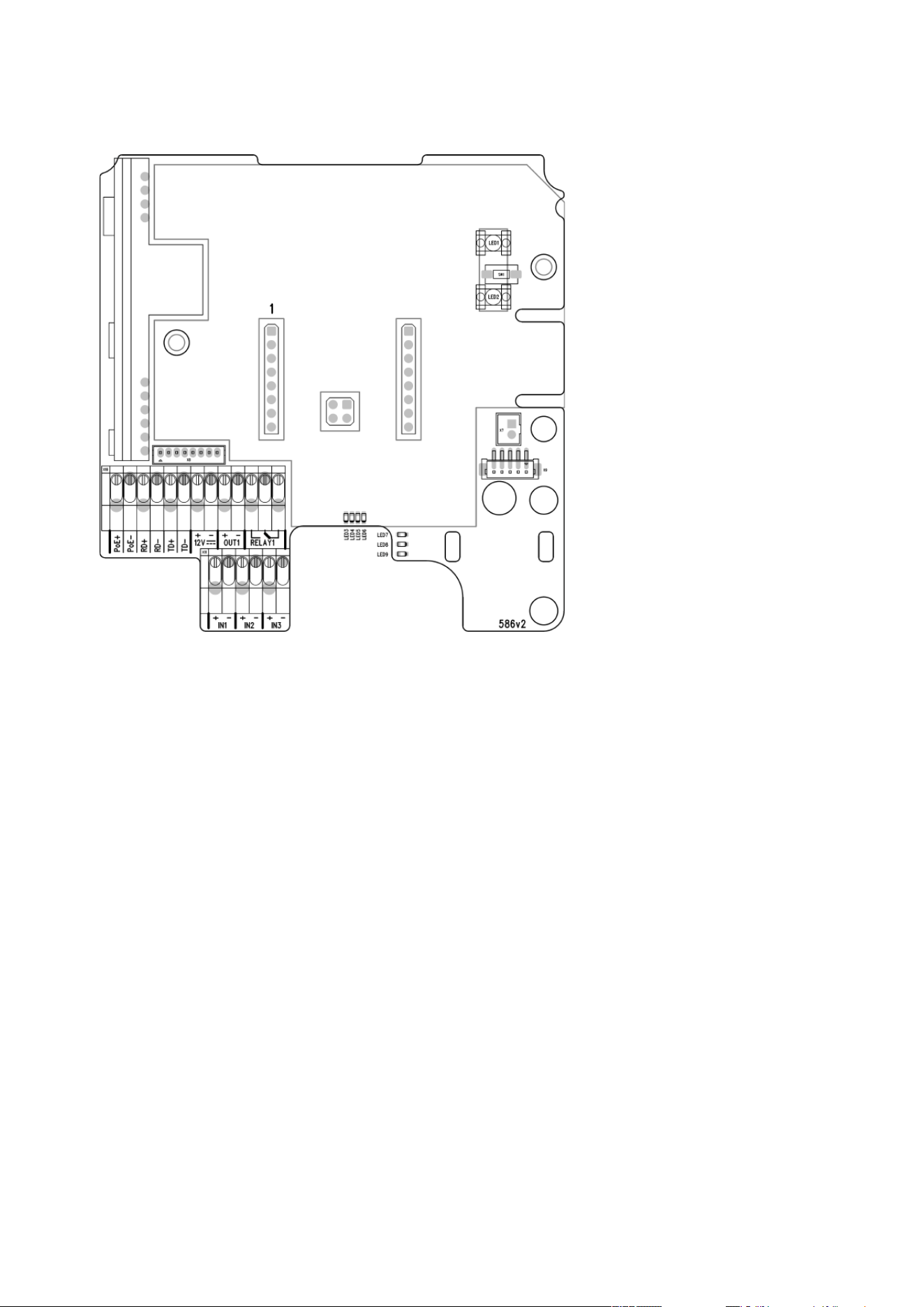
Legend to Figure
PoE, RD, TD LAN (PoE according to 802.1af) terminals
IN1, IN2, IN3 IN1, IN2 and IN3 (available for 2N Access Unit 1.0 only)
terminals used as an input in the passive/active mode (−30 V
to +30 V DC) for departure button, open door sensor, ESS etc.
connection
OFF = open OR U
IN
> 1.5 V
ON = closed contact OR U
IN
< 1.5 V

2N Access Unit Installation Manual
73 / 118
•
•
•
OUT1
OUT1 active output terminals for connection of 2N
®
IP
Security Relay or electric lock: 8 up to 12 V DC depending on
power supply (PoE: 10 V; adapter: power supply voltage
minus 2 V), up to 600 mA
RELAY1 PCB version 599v6 and higher:
RELAY1 terminals with accessible 30 V / 1 A AC/DC NO
contact.
PCB version 599v3 and 599v4:
RELAY1 terminals with accessible 30 V / 1 A AC/DC NO/NC
contact. Used for connection of non-critical devices only
(lights, e.g.).
PCB version 586v2 and higher:
RELAY1 terminals with accessible 30 V / 1 A AC/DC NO/NC
contact. Used for connection of non-critical devices only
(lights, e.g.).
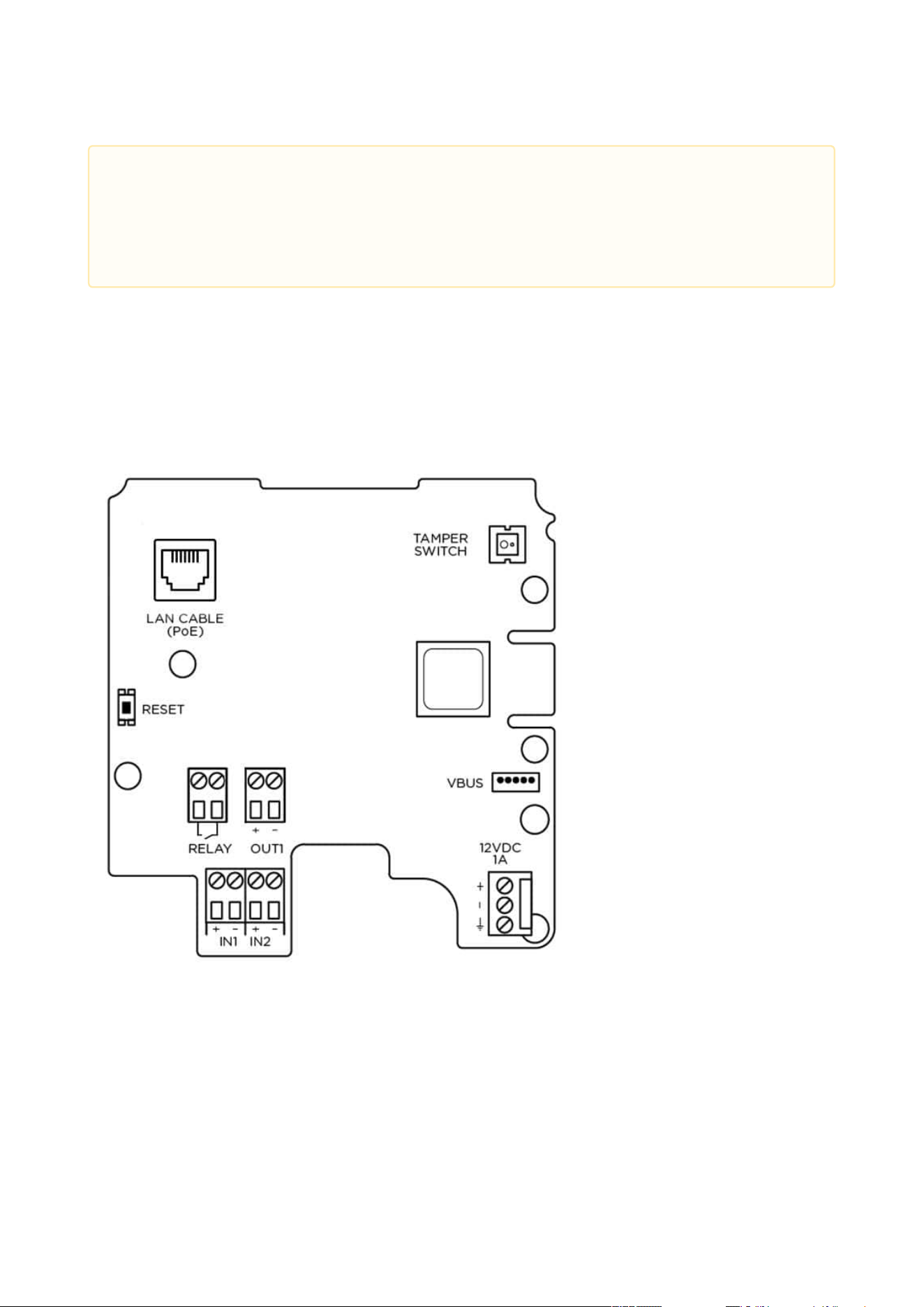
12 V / 1 A External supply terminals for 2N Access Unit – 12 V / 1 A
RESET RESET / FACTORY RESET button
RJ-45 RJ-45 adapter connector – no need to use the PoE, RD and
TD terminals for this connector
2N Access Unit Installation Manual
74 / 118
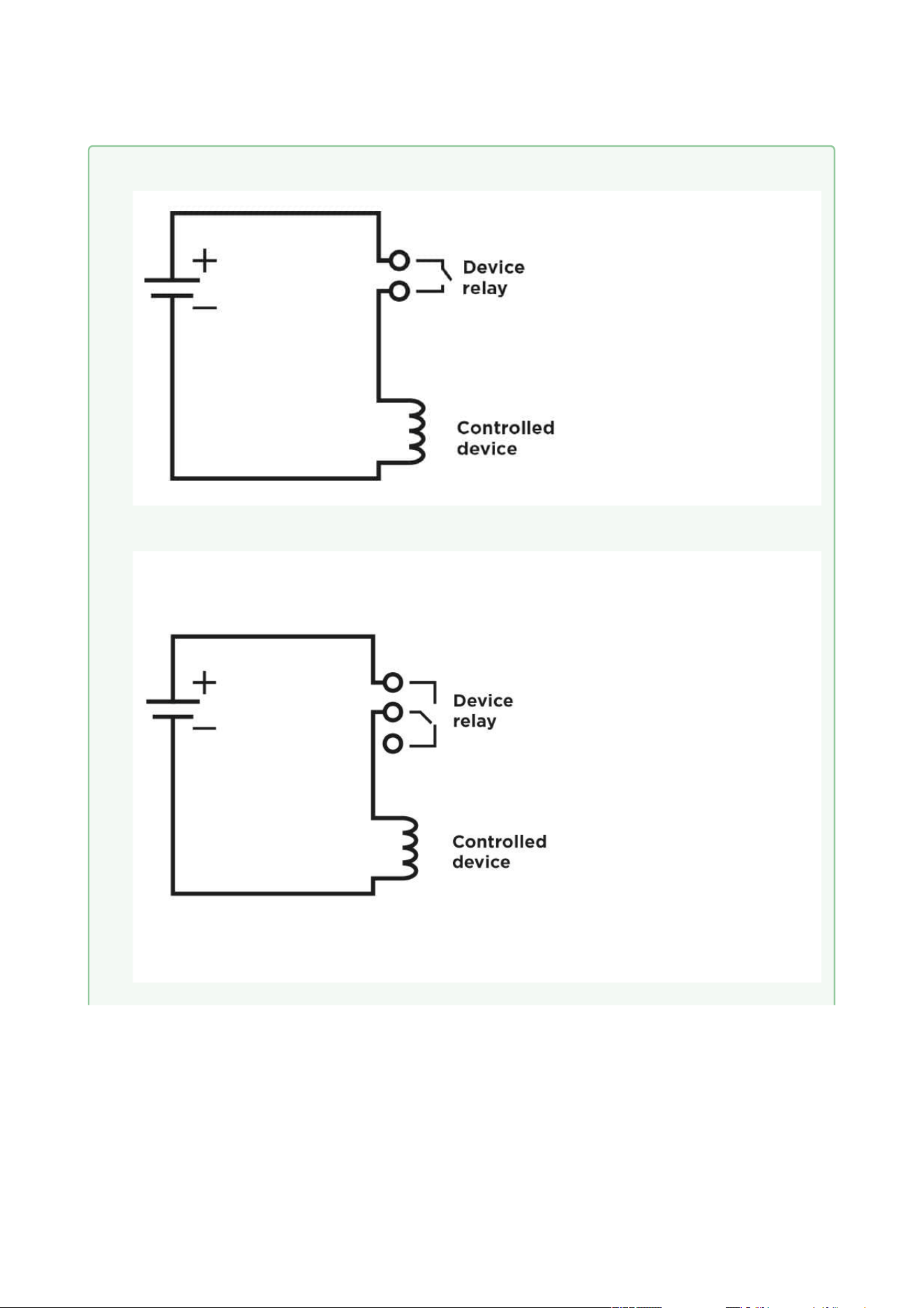
• Output wiring diagram for Relay terminals
Electric circuit closing diagram for controlled devices with PCB version 599v6 and above
Electric circuit closing diagram for controlled devices with PCB version 586v2 and below
2N Access Unit Installation Manual
75 / 118
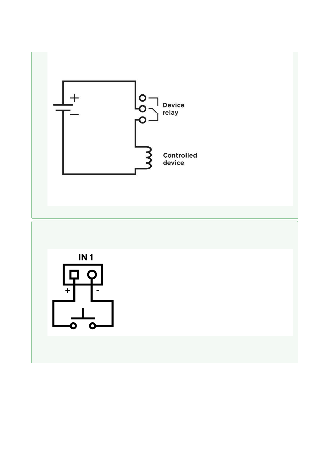
Electric circuit opening diagram for controlled devices with PCB version 586v2 and below
•
•
Tip
Wiring diagram of IN1, IN2 and IN3 terminals in active mode
Wiring diagram of IN1, IN2 and IN3 terminals in passive mode
2N Access Unit Installation Manual
76 / 118
•
•
•
•
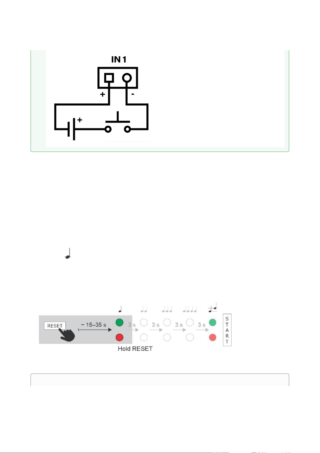
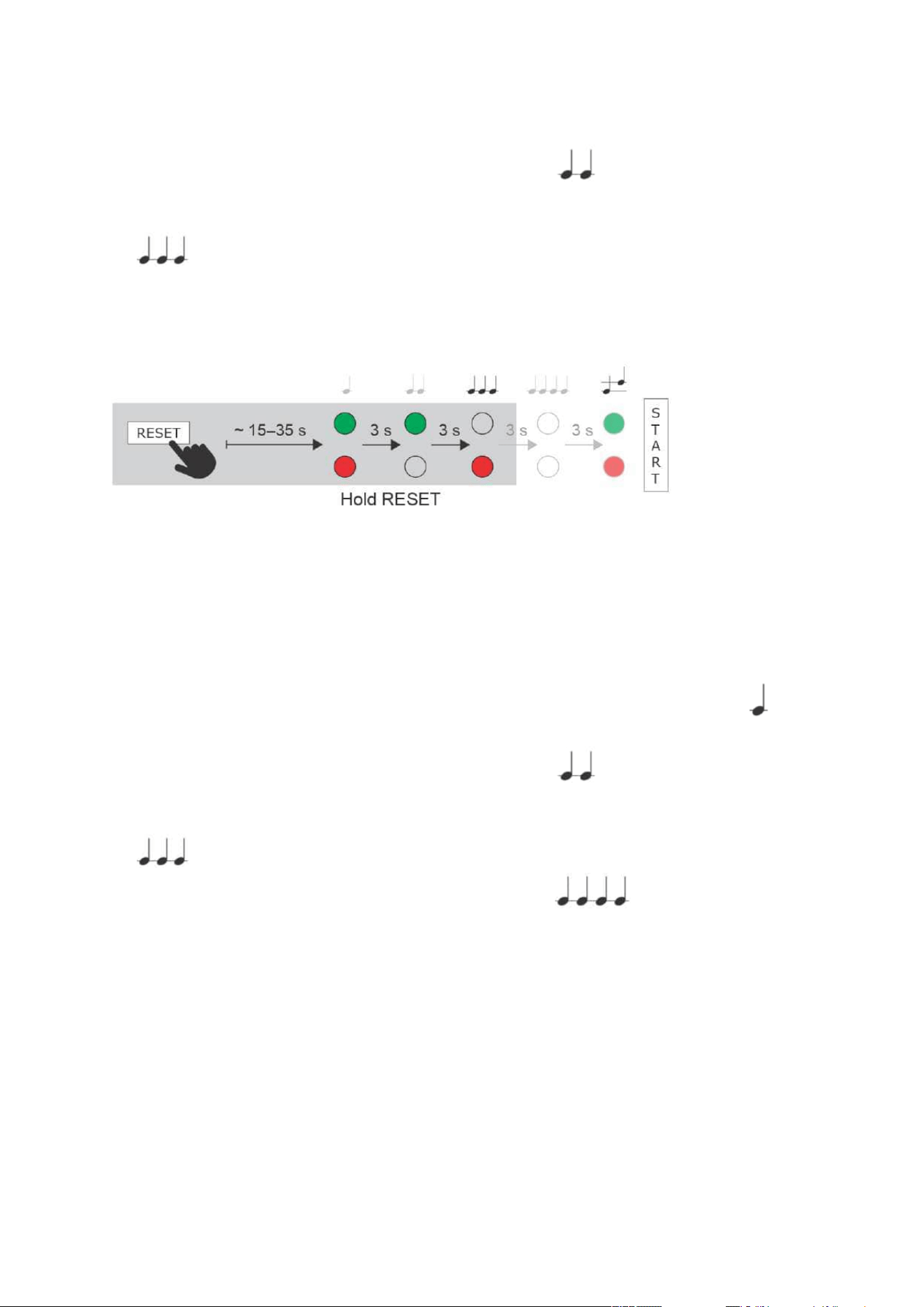
Reset Button
Located among the main unit connectors, the Reset button helps you reset the factory default
values, restart the device, find the device IP address and switch the static/dynamic mode.
IP Address Retrieval
Follow the instructions below to retrievethecurrent IP address:
Press and hold the RESET button.
Wait until the red and green LEDs go on simultaneously on the device and the acoustic
signal can be heard (approx. 15–35 s).
Release the RESET button.
The device automatically announces the current IP address.
Note
2N Access Unit Installation Manual
77 / 118
•
•
•
•
•
•
•
•
•
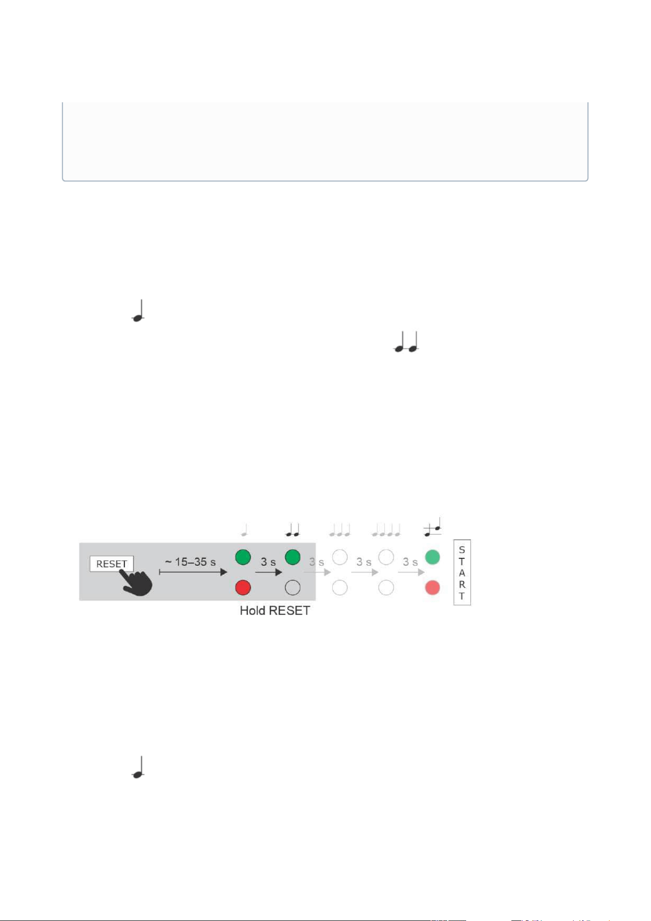
Static IP Address Setting
Follow the instructions below to switch on theStatic IP addressmode (DHCP OFF):
Press and hold the RESET button.
Wait until the red and green LEDs go on simultaneously on the device and the acoustic
signal can be heard (approx. 15–35 s).
Wait until the red LED goes off andthe acoustic signal can be heard (approx. for
another 3 s).
Release the RESET button.
The following network parameters will be set after restart:
IP address: 192.168.1.100
Network mask: 255.255.255.0
Default gateway: 192.168.1.1
Dynamic IP Address Setting
Follow the instructions below to switch on theDynamic IP addressmode (DCHP ON):
Press and hold the RESET button.
Wait until the red and green LEDs go on simultaneously on the device and the acoustic
signal can be heard (approx. 15–35 s).
•
•
The delay after pressing RESET till the first light and sound signalling is set to 15–
35 s depending on the 2N IP intercom/answering unit model used.
42 s is a valid value for 2N Access Unit, 15 s is a valid value for 2N Access
Unit 2.0.
2N Access Unit Installation Manual
78 / 118
•
•
•
•
•
•
•
•
•
Wait until the red LED goes off andthe acoustic signal can be heard (approx. for
another 3 s).
Wait until the green LED goes off and the red LED goes on again andthe acoustic signal
can be heard (approx. for another 3 s).
Release the RESET button.
Factory Reset
Follow the instructions below toreset the factory default values:
Press and hold the RESET button.
Wait until the red and green LEDs go on simultaneously and the acoustic signal can be
heard (approx. 15–35 s).
Wait until the red LED goes off andthe acoustic signal can be heard (approx. for
another 3 s).
Wait until the green LED goes off and the red LED goes on again andthe acoustic signal
can be heard (approx. for another 3 s).
Wait until the red LED goes off andthe acoustic signal can be heard (approx. for
another 3 s).
Release the RESET button.

2N Access Unit Installation Manual
79 / 118
2N Access Unit Installation Manual
80 / 118
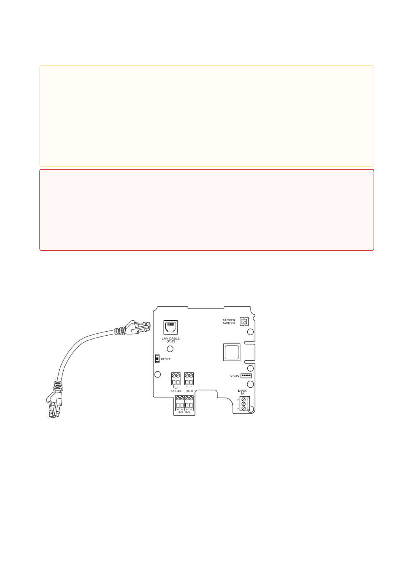
2N Access Unitis equipped with a RESET button. The button is located in the left-hand part
below the LAN connector in PCB version 599v6, between the LED indicators (LED1 and LED2
below) in the right-hand upper part of the unit in version 586v2 and in the middle of the
lower partin version586v4. Press the button shortly (< 1 s) to restart the system without
changing configuration.
2N Access Unit 2.0 Connectors, PCB Version 599v6
•
Caution
In case of resetting the factory default settings on a device with a firmware version
2.18 or higher, it is necessary to reprogram the
2N
®
Security Relay using the instructions from Subsection 2.4.
2N Access Unit Installation Manual
81 / 118
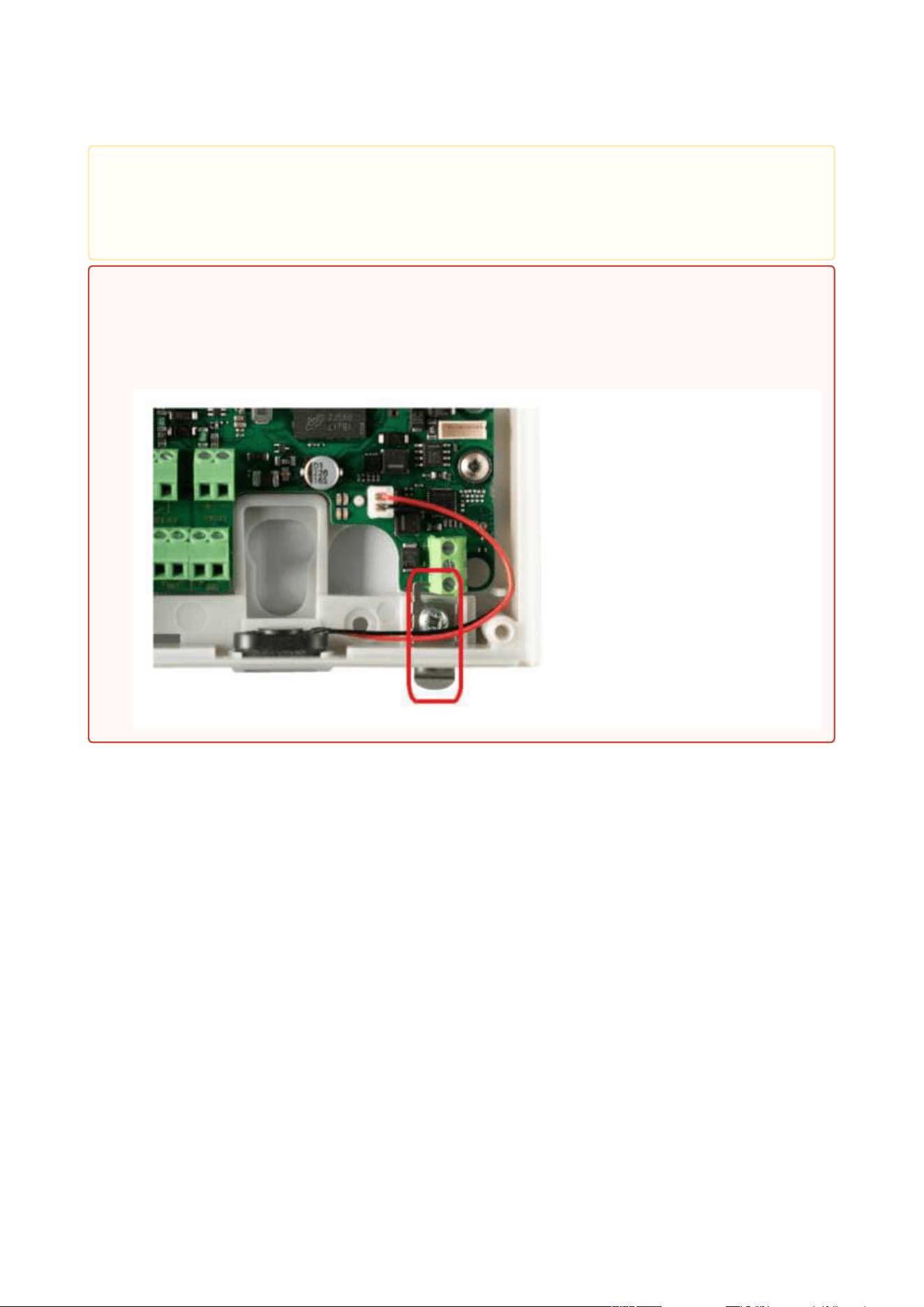
•
Caution
The order of the power supply connector terminals has been changed on and a
small grounding plate has been added to the PCB (version599v6).
•
Warning
Do not remove the small metal plate under the power supply connector. The plate
is necessary for a proper metal frame grounding and its absence may compromise
the resistance against electrostatic discharge.
2N Access Unit Installation Manual
82 / 118
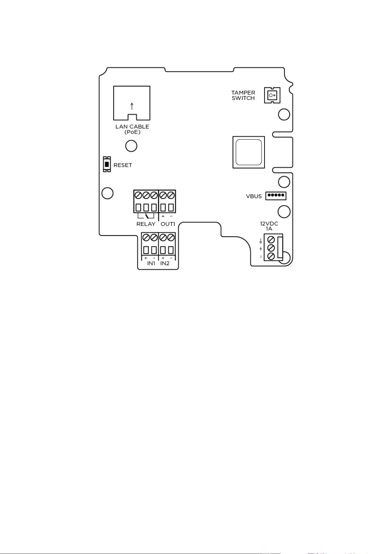
2N Access Unit Connectors, PCB Version 599v3 and 599v4
2N Access Unit Installation Manual
83 / 118
2N Access Unit Connectors, PCB Version 586v2

2N Access Unit Installation Manual
84 / 118
2N Access Unit Connectors, PCB Version 586v4
Device Restart
Press the RESET button shortly (< 1 s) to restart the system without changing configuration.
•
Note
The time interval between the short press of RESET and reconnection after restart
is 49s for2N Access Unit, 14 s for 2N Access Unit 2.0.

2N Access Unit Installation Manual
85 / 118
•
•
•
Available Switches
Location Name Description
Basic unit Relay 1 PCB Version 599v6 and higher:
Passive switch: NO contact, up to 30 V / 1 A
AC/DC. Used for connection of non-critical
devices only (lights, e.g.).
PCB Version 599v3 and 599v4:
Passive switch: NO/NC contact, up to 30 V /
1 A AC/DC. Used for connection of non-
critical devices only (lights, e.g.).
PCB Version 586v2 and higher:
Passive switch: NO/NC contact, up to 30 V /
1 A AC/DC. Used for connection of non-
critical devices only (lights, e.g.).
Output 1 Active switch output: 8 up to 12 V DC
depending on power supply (PoE: 10 V;
adapter: power supply voltage minus 2 V), up
to 600 mA
Tamper switch Helps to secure the system against tampering.
The information about unauthorised
manipulation with the device can be used in
the menu Hardware / Digital Inputs / Tamper
Switch, in Automation a it is also logged in the
Events.
•
Security
The 12V output is used for lock connection. If, however, the unit (2N IP Intercom,
2N Access Unit) is installed where unauthorized tampering may happen, we
strongly recommend that the 2N
®
Security Relay (Part No. 9159010) be used for
enhanced installation security.
2N Access Unit Installation Manual
86 / 118
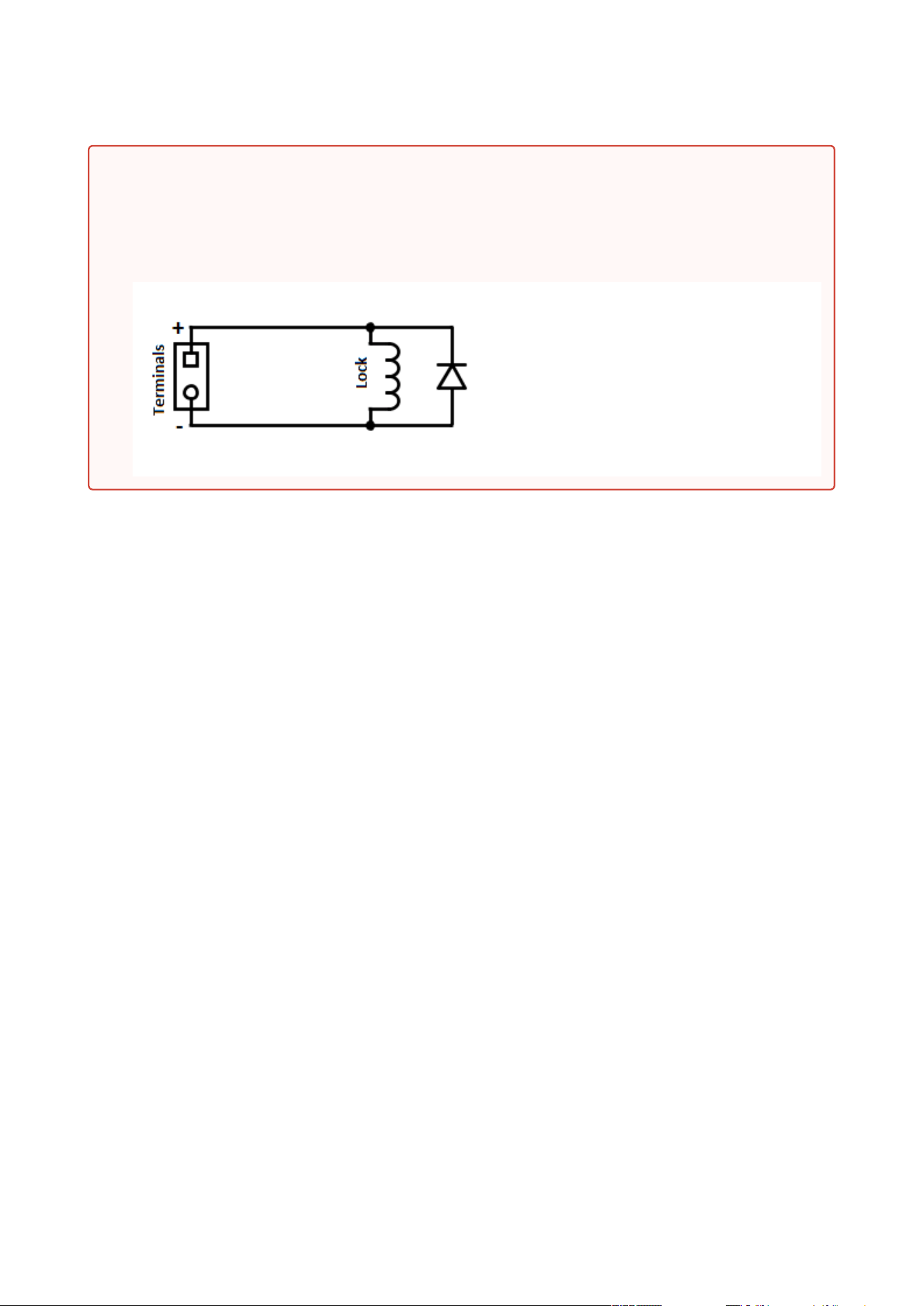
Warning
When you connect a device containing a coil, such as a relay or an electromagnetic lock,
it is necessary to protect the intercom output against voltage peak while switching off
the induction load. For this way of protection we recommend a 1 A / 1000 V diode (e.g.,
1N4007, 1N5407, 1N5408) connected antiparallel to the device.
2N Access Unit Installation Manual
87 / 118
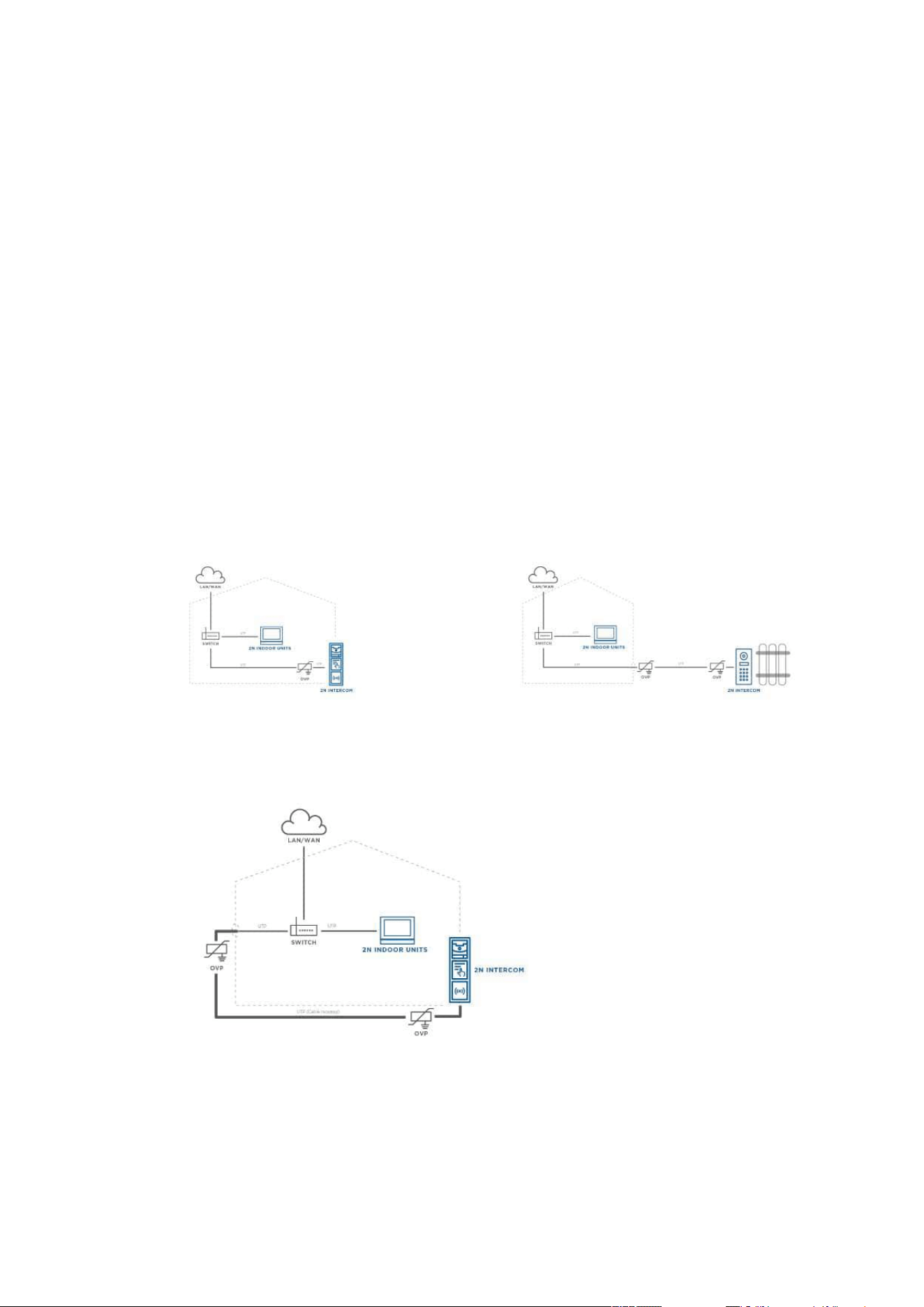
2.3.1 Overvoltage Protection
Recommendations for Additional Overvoltage Protector Installation
If running:
a) outside a building,
b) on/in an outer wall or roof,
the 2N device wiring may be exposed to atmospheric effects resulting in overvoltage that may
subsequently damage any devices installed outside the building, on its outer wall or roof.
Overvoltage may damage devices connected to these wires and installed inside the building as
well. Therefore, we recommend that additional surge protectors be installed on all the wires
leading outside buildings, on outer walls or roofs, namely:
a) as close as possible to the device installed outside the building or on its outer wall/roof,
b) as close as possible to the point where the wires leave the building.
Examples of overvoltage protection:
OVP = overvoltage
protection

2N Access Unit Installation Manual
88 / 118
•
•
•
•
•
•
•
•
•
•
•
•
•
•
•
•
•
2.4 Extending Module Connection
2NAccess Unitallows to connect following extending modules:
5 Buttons
Keypad
Touch Keypad
Touch Display
125 kHz RFID Card Reader
13.56 MHz RFID Card Reader
13.56 MHz RFID Card Reader, NFC supporte
Bluetooth & RFID Reader 125 kHz, 13.56 MHz, NFC
Bluetooth & RFID Reader 125 kHz, secured 13.56 MHz, NFC
Touch Keypad & RFID Reader 125 kHz, 13.56 MHz, NFC
Touch Keypad & RFID Reader 125 kHz, secured 13.56 MHz, NFC
Bluetooth Reader
Fingerprint Reader
I/O Module
Infopanel
Wiegand
Security Relay
Module Bus Interconnection
All the modules that can be connected to2NAccess Unitare interconnected via a bus. The bus
starts on the basic unit and goes over all the modules. The order of modules on the bus is
irrelevant. And it also irrelevant which bus connector on the module is used as the input and
which is used as the output.
The modules include a 220 mm long bus interconnecting cable;Part No. 9155037Wiegand
modules andPart No. 9155034I/O modules include an 80 mm long bus cable.These two
modules can be hidden inside one of the modules described below (Infopanel, Keypad, RFID
card reader, Bluetooth) and/or placed freely behind a standalone access unit (in a mounting
box, e.g.).
It is possible to order separate bus cables of the lengths of 1 m, 3 m, or 5 m (Part
Nos.9155050/9155054/9155055), which are designed for remote2N Access Unitmodule
installations. Typically, they are used for an RFID card reader mounted on a wall opposite to
the2N Access Unitinstallation. The cable may be used only once on the bus. In extensive
installations, the total bus cable length may not exceed 7 m.
Module Power Supply
All the modules connected to2NAccess Unit, except for the Tamper Switch, are powered from
the bus. The available bus power output depends on the power supply type. The basic unit can
use a 2 A power supply to increase the bus power available to the modules connected.

2N Access Unit Installation Manual
89 / 118
Power supply Specification Available power output
External supply 12 V ±15% / 1 A 12 W
PoE 802.3af (Class 0–12.95 W) 12 W
The count of modules on the bus is limited by the available power supply output. The maximum
count of the modules on the bus is 30.
Basic unit
(571v3)
Consumption [W]
(Maximum value)
At relax 1.2
OUT 1 4.8
Total 6
Module Idle consumption [W]
(Minimum value)
Full load [W]
(Maximum value)
Special elements[W]
Basic unit (586v3) 1.2 6
Infopanel (580v2) 0.17 0.64
Keypad (579v2) 0.20 1.55
125 kHz RFID card reader
(584v2)
13.56 MHz RFID card
reader (583v2)
0.42 0.89
Bluetooth module
(2271v2)
0.15 0.3
I/O module (577v2) 0.35 0.66 Closed relay 0.13
Wiegand module (581v1)
Specimen configuration consumption computation:
Module Minimum consumption [W] Maximum consumption [W]
Basic unit 1.2 6

2N Access Unit Installation Manual
90 / 118
•
•
•
•
•
•
•
•
•
•
Module Minimum consumption [W] Maximum consumption [W]
13.56 MHz RFID card reader
(583v2)
0.42 0.89
I/O module (577v2) 0.35 0.66
Tamper switch 0 0
Wiegand module (581v1) x x
Total 2.07 7.55
It is obvious from the specimen configuration that all the modules have sufficient outputs when
an external power supply is used. When a PoE supply is used, the power output is insufficient for
all the modules, which results in automatic decrease in backlight level, active output current
supply, volume and LED intensity.
Some modules need a specific power output for their specific activities: the I/O module, e.g.,
requires 0.13 W for relay closing (not included in the minimum consumption).
5 Buttons Module
The Buttons module (PartNo.9155035)is used for dialling selected Automation functions.
The module contains two bus connectors for2NAccess Unit.
These two connectors are fully interchangeable and can be used either as inputs from the
basic unit or outputs to other modules.
If this module is the last one on the bus, one of the connectors remains unconnected.
The module package includes a 220 mm long interconnecting cable.
Keypad Module
The Keypad module (Part No. 9155031) is used for a numeric access to the system.
The module contains two bus connectors for2NAccess Unit.
These two connectors are fully interchangeable and can be used either as inputs from the
basic unit or outputs to other modules.
If this module is the last one on the bus, one of the connectors remains unconnected.
The module package includes a 220 mm long interconnecting cable.
Touch Keypad
The Touch keypad (Part No.9155047) provides a numerical input in the system.
The module contains two2NAccess Unitbus connectors.
These two connectors are fully interchangeable and can be used both as inputs from the
main unit and outputs to other modules.

2N Access Unit Installation Manual
91 / 118
•
•
•
•
•
•
•
•
•
•
•
•
•
•
•
•
If this module is the last one on the bus, one of the connectors remains unconnected.
The module package includes a 220 mm long interconnecting cable.
TouchDisplay
TheTouch display(Part No.9155036)can be used as:
Infopanel module – displays user defined image sequences
Keypad module – virtual touch keypad
Button module – virtual phone directory
Module connection options:
The module contains two2NAccess Unit.bus connectors.
These two connectors are fully interchangeable and can be used both as inputs from the
basic unit and outputs to other modules.
If this module is the last one on the bus, one of the connectors remains unconnected.
The module package includes a 220 mm long interconnecting cable.
Technical specification:
Resolution: 320 px x 214 px H x V
Resolution slideshow: 214 px x 214 px
Contrast ratio: 400
Brightness: 350 cd/m2
Weight: 280 g
Working temperature: −20 °C – 60 °C
Resistance level: IK07
•
Caution
The display is not supported on Access Unit 1.0 from FW version 2.27.

2N Access Unit Installation Manual
92 / 118
•
•
•
•
•
•
•
•
•
•
•
•
•
•
•
•
•
•
•
•
125 kHz RFID Card Reader Module
The 125kHz RFID card reader module (Part No. 9155032) is used for reading RFID card Ids in the
125 kHz band.
The module contains two bus connectors for2NAccess Unit.
These two connectors are fully interchangeable and can be used either as inputs from the
basic unit or outputs to other modules.
If this module is the last one on the bus, one of the connectors remains unconnected.
The module package includes a 220 mm long interconnecting cable.
The following RFID cards can be read:
EM4xxx
13.56 MHz RFID Card Reader, NFC support
The 13.56 MHz RFID card reader (Part No.9155040) isused for reading RFID card Ids in the
13.56 MHz band.
The module contains twobus connectors.
These two connectors are fully interchangeable and can be used both as inputs from the
main unit and outputs to other modules.
If this module is the last one on the bus, one of the connectors remains unconnected.
The module package includes a 220 mm long interconnecting cable.
The following RFID cards can be read (only the card serial number is read):
ISO14443A (Mifare, DESFire)
PicoPass (HID iClass)
FeliCa
ST SR(IX)
2N
®
Mobile Key
Bluetooth & RFID Reader 125 kHz, 13.56 MHz, NFC
Bluetooth with a combined 125 kHz and 13.56 MHz card reader module (Part No. 9155082)
isused for Smartphone/2N
®
Mobile Key tablet/card access control, making user calls and/or
other functions.
NFC – a licensed function, for 2N
®
Mobile Key for Android only.
The module contains two bus connectors.
These two connectors are fully interchangeable and can be used either as inputs from the
basic unit or outputs to other modules.
If this module is the last one on the bus, one of the connectors remains unconnected.
The module package includes a 220 mm long interconnecting cable.
The following RFID cards can be read:
125 kHz

2N Access Unit Installation Manual
93 / 118
•
•
•
•
•
•
•
•
•
•
•
•
•
•
•
•
•
•
•
•
EM4xxx
13.56 MHz
ISO14443A (Mifare, DESFire)
PicoPass (HID iClass)
FeliCa
ST SR(IX)
2N
®
Mobile Key
Bluetooth & RFID Reader 125 kHz, secured 13.56 MHz, NFC
Bluetooth with a combined 125 kHz and secured 13.56 MHz card reader (Part No. 9155084) is
used for Smartphone/2N
®
Mobile Key tablet/card access control, making user calls and/or other
functions.
NFC – a licensed function, for 2N
®
Mobile Key for Android only.
The module contains two bus connectors.
These two connectors are fully interchangeable and can be used either as inputs from the
basic unit or outputs to other modules.
If this module is the last one on the bus, one of the connectors remains unconnected.
The module package includes a 220 mm long interconnecting cable.
The following RFID cards can be read:
125 kHz
EM4xxx
13.56 MHz
ISO14443A (Mifare, DESFire)
PicoPass (HID iClass)
FeliCa
ST SR(IX)
2N
®
Mobile Key
HID SE (Seos, iClass SE, Mifare SE)
•
Tip
To accelerate card reading, you are recommended to select the card types used by
the user in the module settings.
•
Tip
To accelerate card reading, you are recommended to select the card types used by
the user in the module settings.

2N Access Unit Installation Manual
94 / 118
•
•
•
•
•
•
•
•
•
•
•
•
•
•
•
•
•
•
•
•
•
Touch Keypad & RFID Reader 125 kHz, 13.56 MHz, NFC
The touch keypad with a combined 125 kHz and 13.56 MHz card reader(Part No. 9155081) is
used for code/card access control, making user calls and/or other functions. The keypad surface
is very sensitive yet weatherproof at the same time.
NFC – a licensed function, for 2N
®
Mobile Key for Android only.
The module contains two bus connectors.
These two connectors are fully interchangeable and can be used either as inputs from the
basic unit or outputs to other modules.
If this module is the last one on the bus, one of the connectors remains unconnected.
The module package includes a 220 mm long interconnecting cable.
The following RFID cards can be read:
125 kHz
EM4xxx
13.56 MHz
ISO14443A (Mifare, DESFire)
PicoPass (HID iClass)
FeliCa
ST SR(IX)
2N
®
Mobile Key
Touch Keypad & RFID Reader 125 kHz, secured 13.56 MHz, NFC
The touch keypad with a combined 125 kHz and secured 13.56 MHz card (Part No. 9155083)
reader isused for code/card access control, making user calls and/or other functions. The
keypad surface is very sensitive yet weatherproof at the same time.
NFC – a licensed function, for 2N
®
Mobile Key for Android only.
The module contains two bus connectors.
These two connectors are fully interchangeable and can be used either as inputs from the
basic unit or outputs to other modules.
If this module is the last one on the bus, one of the connectors remains unconnected.
The module package includes a 220 mm long interconnecting cable.
The following RFID cards can be read:
125 kHz
EM4xxx
13.56 MHz
•
Tip
To accelerate card reading, you are recommended to select the card types used by
the user in the module settings.

2N Access Unit Installation Manual
95 / 118
•
•
•
•
•
•
•
•
•
•
•
•
•
•
•
•
•
•
•
ISO14443A (Mifare, DESFire)
PicoPass (HID iClass)
FeliCa
ST SR(IX)
2N
®
Mobile Key
HID SE (Seos, iClass SE, Mifare SE)
Touch Keypad & Bluetooth & RFID Reader 125 kHz, 13.56 MHz, NFC
The touch keypad with Bluetooth and a combined 125 kHz and secured 13.56 MHz card reader
(Part No. 91550947) is one of the 2N
®
IP Verso intercom elements and is used for code/card
access control using a smartphone or tablet with the 2N
®
Mobile Key application, making user
calls and/or control of other functions. The keypad surface is very sensitive yet weatherproof at
the same time.
NFC – a licensed function, for 2N
®
Mobile Key for Android only.
The module contains two bus connectors.
These two connectors are fully interchangeable and can be used either as inputs from the
main unit or outputs to other modules.
If this module is the last one on the bus, one of the connectors remains unconnected.
The module package includes a 220 mm long interconnecting cable.
The following RFID cards can be read:
125 kHz
EM4xxx
13.56 MHz
ISO14443A (Mifare, DESFire)
PicoPass (HID iClass)
FeliCa
ST SR(IX)
2N
®
Mobile Key
Touch Keypad & Bluetooth & RFID Reader 125kHz, Secured 13.56 MHz, NFC
The touch keypad with Bluetooth and a combined 125 kHz and secured 13.56 MHz card reader
(Part No. 91550947-S) is one of the 2N
®
IP Verso intercom elements and is used for code/card
access control using a smartphone or tablet with the 2N
®
Mobile Key application, making user
•
Tip
To accelerate card reading, you are recommended to select the card types used by
the user in the module settings.

2N Access Unit Installation Manual
96 / 118
•
•
•
•
•
•
•
•
•
•
•
•
•
•
calls and/or control of other functions. The keypad surface is very sensitive yet weatherproof at
the same time.
NFC – a licensed function, for 2N
®
Mobile Key for Android only.
The module contains two bus connectors.
These two connectors are fully interchangeable and can be used either as inputs from the
main unit or outputs to other modules.
If this module is the last one on the bus, one of the connectors remains unconnected.
The module package includes a 220 mm long interconnecting cable.
The following RFID cards can be read:
125 kHz
EM4xxx
13.56 MHz
ISO14443A (Mifare, DESFire)
PicoPass (HID iClass)
FeliCa
ST SR(IX)
2N
®
Mobile Key
HID SE (Seos, iClass SE, Mifare SE)
Caution
Press the button with a key symbol on the reader (without entering numbers before) of
the touch keypad & Bluetooth & RFID reader module to start Bluetooth authentication.

2N Access Unit Installation Manual
97 / 118
•
•
•
•
•
•
•
•
•
•
•
•
•
•
•
•
Bluetooth Reader
The Bluetooth reader module (Part No. 9155046) helps authenticate and subsequently open
doors using Android and iOS based smartphones via the Bluetooth protocol 4.0 as RFID card
replacement. Install the 2N
®
Mobile Key application fromGoogle PlayandAppstoreto make
authentication work properly. The application requires phones with Android OS6.0
Marshmallow and higher and iOS 12 and higher.
The module contains two 2NAccess Unit bus connectors.
The two connectors are fully interchangeable and can be used both as inputs from the
main unit or outputs to other modules.
If this module is the last one on the bus, one of the connectors remains unconnected.
The package includes a 220 mm long interconnecting cable.
The module uses the 2.4 GHz frequency.
IDs from the following smart phones can be read:
Android 6.0 and higher
iPhone 4S and higherwith iOS 12and higher
Fingerprint Reader
TheFingerprint readeris used for automated verification of human fingers for access control
and intercom control.
The module contains two2NAccess Unitbus connectors.
These two connectors are fully interchangeable and can be used both as inputs from the
main unit and outputs to other modules.
If this module is the last one on the bus, one of the connectors remains unconnected.
The module package includes a 220 mm long interconnecting cable.
Important module properties:
FBI PIV and Mobile ID certification – FAP20
Durable glass touch surface
Rejects spoof fingerprints
−20 to 55 ºC operating temperature range
0–90% relative humidity, noncondensing
•
Warning
The fingerprint reader is not intended for direct sunlight installation sites.
Installation at such places may result in erroneous behavior.
Note
2N Access Unit Installation Manual
98 / 118
•
•
•
•
•
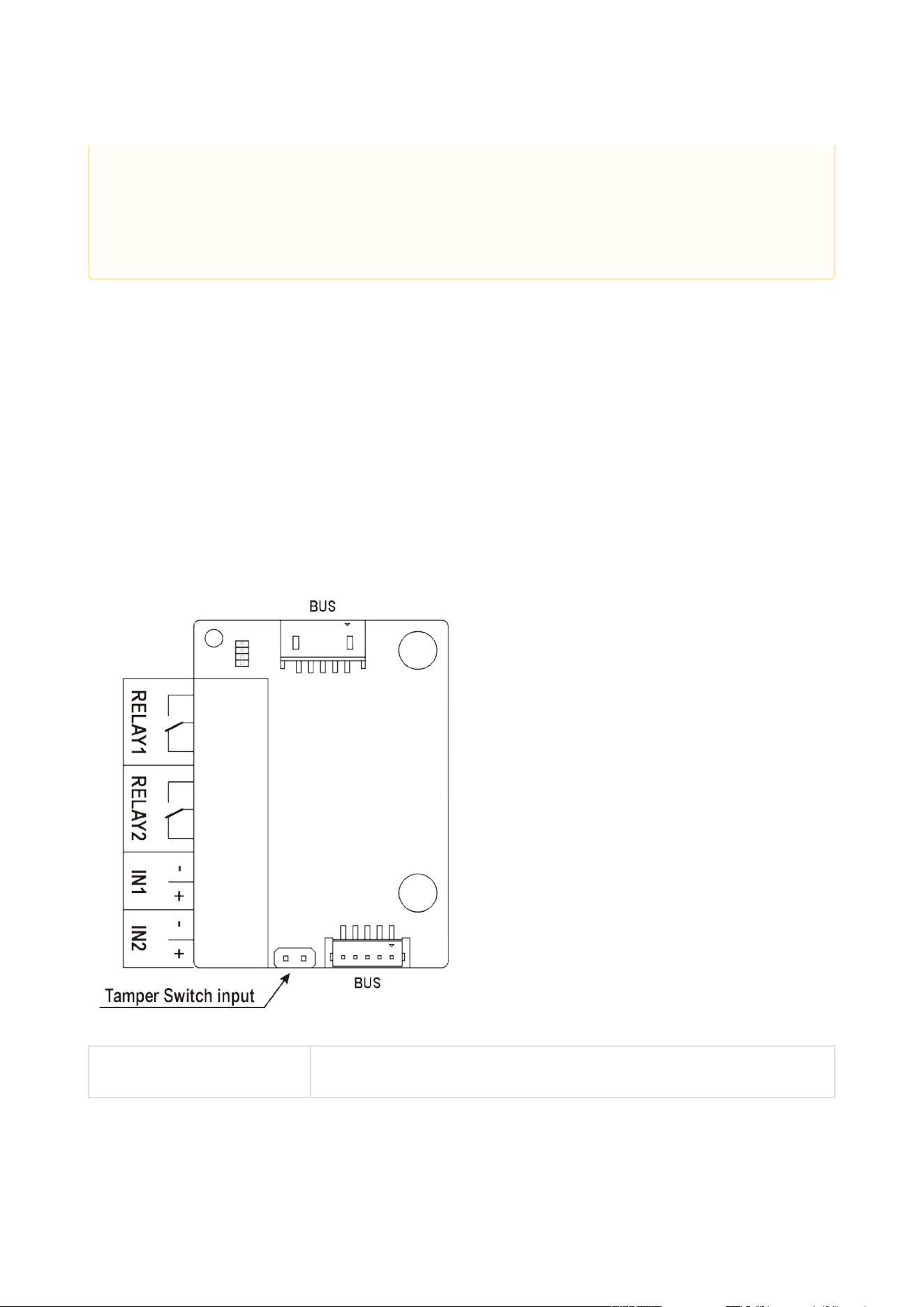
I/O Module
The I/O module (Part No. 9155034) is used for extending of the number of inputs and outputs.
The module contains two bus connectors for2NAccess Unit.
These two connectors are fully interchangeable and can be used either as inputs from the
basic unit or outputs to other modules.
If this module is the last one on the bus, one of the connectors remains unconnected.
The module package includes an 80 mm long interconnecting cable.
The inputs / outputs are addressed as follows:<module_name>.<input/output_name>,
e.g. module5.relay1. Configure the module name in the Module name parameter in the
Hardware / Extenders menu.
RELAY1 RELAY1 terminals with accessible 30 V / 1 A AC/DC NO/NC contact
•
•
A higher moisture may deteriorate finger papillary line scanning. You are advised
to dry your finger and the reader scanning surface for successful authentication.
Fingerprint scanning can be rather difficult with older persons whose papillary
lines are no so distinct (lower finger elasticity due to age requires a higher pressure
for scanning and the fingerprint might be blurred).

2N Access Unit Installation Manual
99 / 118
•
•
•
•
•
•
•
•
•
•
•
RELAY2 RELAY2 terminals with accessible 30 V / 1 A AC/DC NO/NC contact
IN1 IN1 terminals for input in passive/ active mode (−30 V to +30 V
DC)
OFF = open or U
IN
> 1.5 V
ON = short-circuit or U
IN
< 1.5 V
IN2 IN2 terminals for input in passive/active mode (−30 V to +30 V DC)
OFF = open or U
IN
> 1.5 V
ON = short-circuit or U
IN
< 1.5 V
TAMPER Tamper switch input, Part No. 9155038
Infopanel Module
The Infopanel module (Part No. 9155030) is used for inserting and backlighting of printed
information.
The module contains two bus connectors for2NAccess Unit.
These two connectors are fully interchangeable and can be used either as inputs from the
basic unit or outputs to other modules.
If this module is the last one on the bus, one of the connectors remains unconnected.
The module package includes a 220 mm long interconnecting cable.
Name tag dimensions: 69.2 (W) x 86.7 (H) mm (dimensional tolerance: +0; −0.5 mm).
For the printing template refer towww.2n.cz
Wiegand Module
The Wiegand module (Part No. 9155037) helps connect an external Wiegand device (RFID card
reader, fingerprint or other biometric data reader) and/or connect 2NAccess Unitto an external
security exchange. All the inputs and outputs are galvanically isolated from2NAccess Unitwith
the insulation strength of 500 V DC.
The module contains two bus connectors for2NAccess Unit.
These two connectors are fully interchangeable and can be used either as inputs from the
basic unit or outputs to other modules.
If this module is the last one on the bus, one of the connectors remains unconnected.
The module package includes an 80 mm long interconnecting cable.
Configure the module name in the Module name parameter in the Hardware / Extenders
menu.
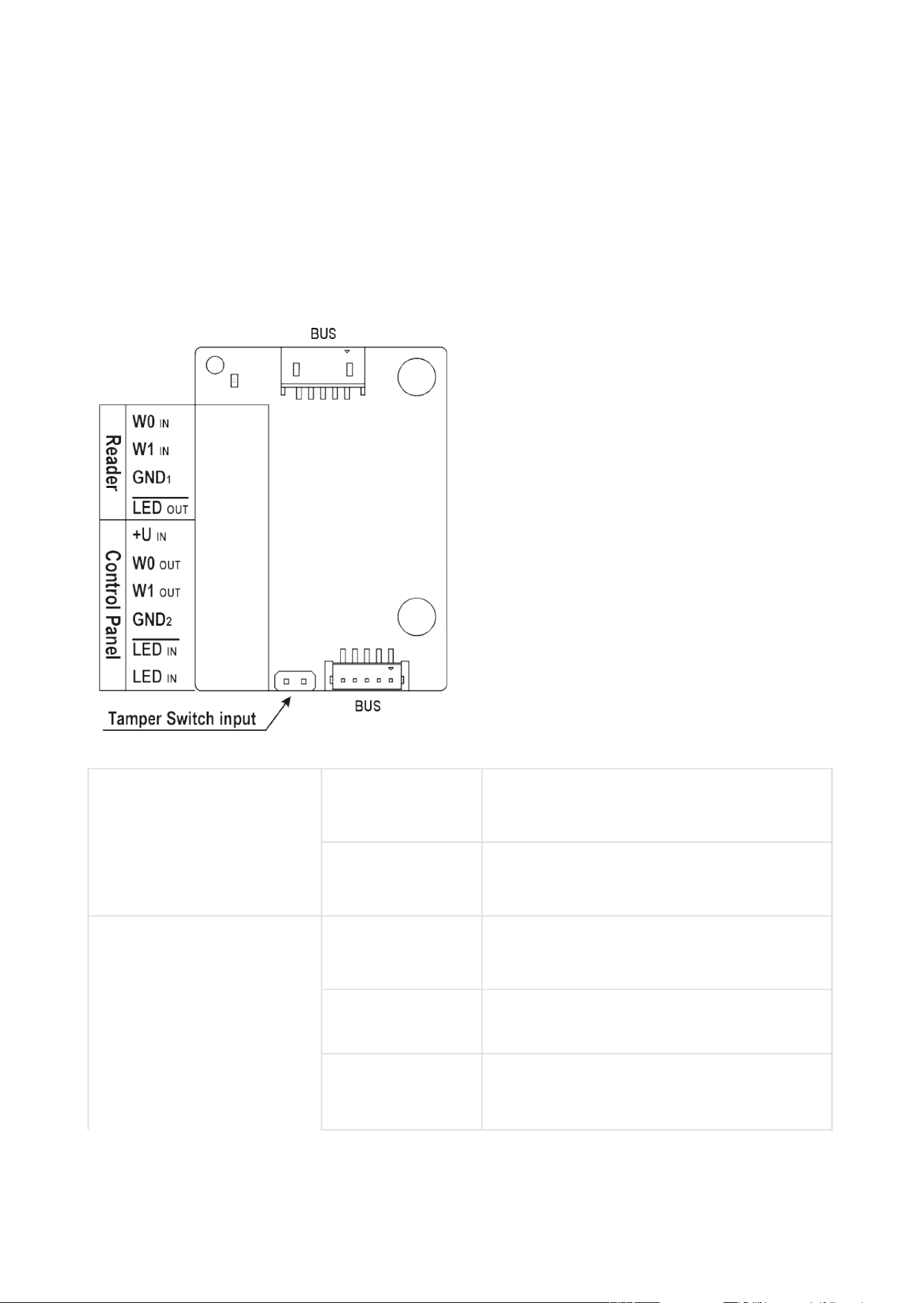
2N Access Unit Installation Manual
100 / 118
•
•
•
The LED IN input is addressed as follows:<module_name>.<input1>, e.g.
module2.input1.
The Tamper input is addressed as follows:<module_name>.<tamper>, e.g.
module2.tamper.
The LED OUT (negated) output is addressed as
follows:<module_name>.<output1>, e.g. module2.output1.
Reader W0IN,W1 IN,
GND1
Isolated 2-wire WIEGAND IN
LEDOUT Isolated open LED OUT switched against
GND1(up to 24 V / 50 mA)
Control Panel +UIN +U (5 to 15 V DC) WIEGAND OUT power
supply input
W0OUT,W1 OUT,
GND2
Isolated 2-wire WIEGAND OUT
LEDIN
(negated)
Isolated input for open LED IN, input
activated by GND
2
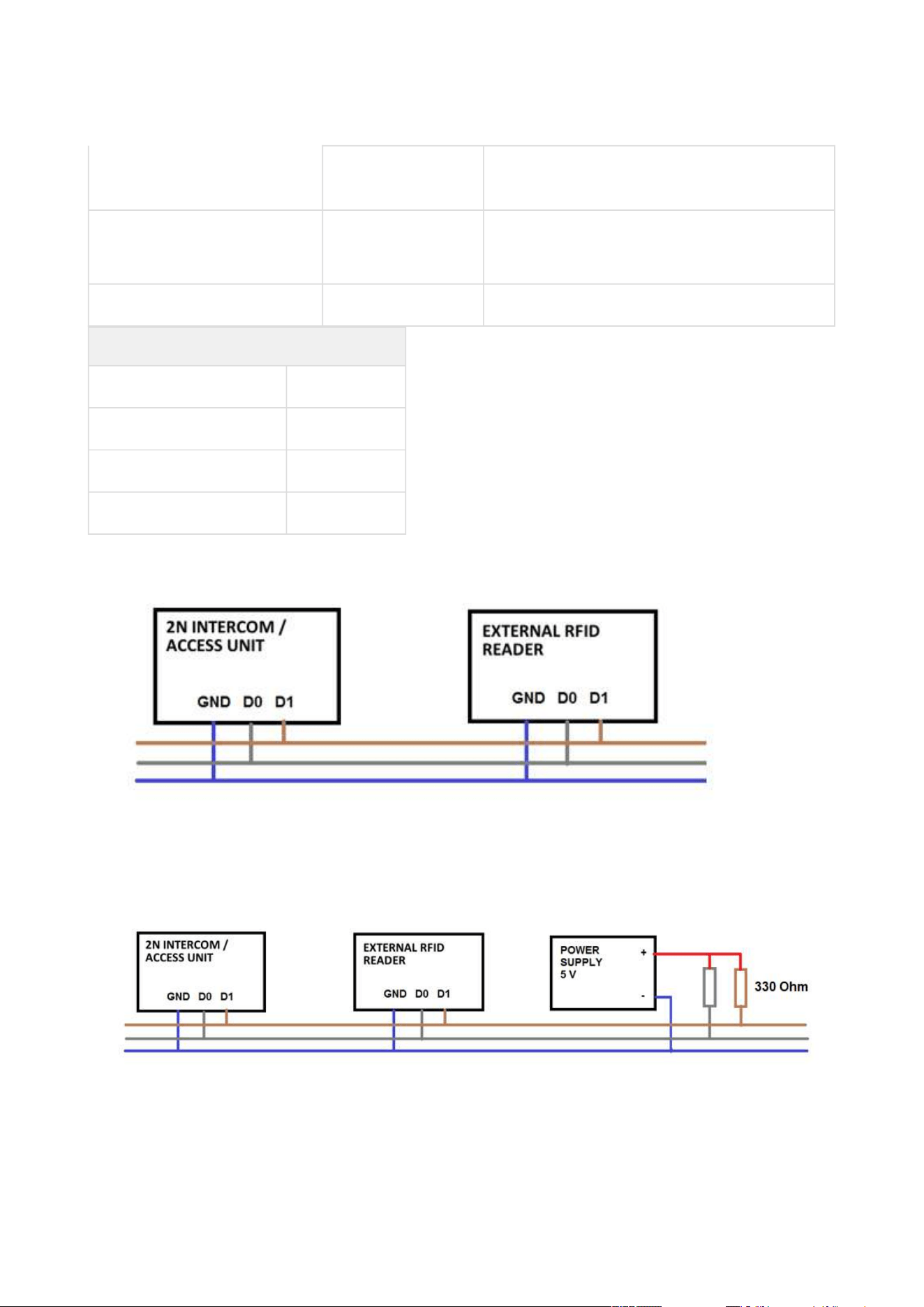
2N Access Unit Installation Manual
101 / 118
LEDIN Isolated input for open LED IN, input
activated by +U
G active supply LED indicator +UINWIEGAND
OUT
TAMPER Tamper switch input, Part No. 9155038
Wiegand Input Technical Parameters
Current 5 mA
Input resistance 680 Ohm
Pulse length 50 μs
Delay between pulses approx. 2 ms
Recommended Wiring Diagram for Reader with Bus Driver
Recommended Wiring Diagram for Reader with Open Collector (OC) Output

2N Access Unit Installation Manual
102 / 118
•
•
2N
®
IPSecurity Relay
The 2N
®
IPSecurity relay(Part No. 9159010) is used for enhancing security between the access
unit and the connected electric lock. It significantly enhances security of the connected electric
lock as it prevents unlocking by forced opening of the2NAccess Module.
Function:
The 2N
®
IPSecurity relayis a device installed between the access unit (outside the secured
area) and an electric lock (inside the secured area).The 2N
®
IPSecurity relayincludes a relay
that can only be activated if the valid opening code is received from the access unit.
Specifications:
Passive switch: NO and NC contacts, up to 30 V / 1 A AC / DC
Switched output:
Where the security relay is fed from the intercom, 9 to 13 V DC is available on the output
depending on the power supply (PoE: 9 V; adapter: source voltage of minus 1 V) / 400 mA
DC.
Where the security relay is fed from an external power supply, 12 V / 700 mA DC is available
on the output.
Dimensions: (56 x 31 x 24) mm
Weight: 20 g
Installation:
The 2N
®
IPSecurity relayis installed onto a two-wire cable between the access unit and the
electric lock inside the area to be secured (typically behind the door). The device is powered and

2N Access Unit Installation Manual
103 / 118
•
•
controlled via this two-wire cable and so can be added to an existing installation. Thanks to its
compact dimensions, the device can be installed into a standard mounting box.
Connection:
Connectthe 2N
®
IPSecurity relay tothe 2NAccess Unit as follows:
To the active output (OUT1)
Connect the electric lock tothe 2N
®
IPSecurity relayas follows:
To the switched output.
To the passive output in series with the external power supply.
The device also supports a Departure button connected between the ‘PB’ and ‘– HeliosIP/2N IP
intercom’ terminals. Press the Departure button to activate the output for 5 seconds.
Status signalling
Green LED Red LED Status
flashing off Operational mode
on off Activated output
flashing flashing Programming mode – waiting for
initialisation
on flashing Error – wrong code received
Configuration:
Connectthe2N
®
IP Security relayto the properly set access unit security output. For settings
refer to the2NAccess Unit Configuration Manualis installed. Make sure that one LED at least is
on or flashing.
Press and holdthe 2N
®
IPSecurity relayReset button for 5 seconds to put the device in the
programming mode (both the red and green LEDs are flashing).
Activate the output switch using the keypad, telephone, etc. The first code sent from the
intercom will be stored in the memory and considered valid. After code initialisation,the
2N
®
IPSecurity relaywill pass into the operational mode (green LED flashing).
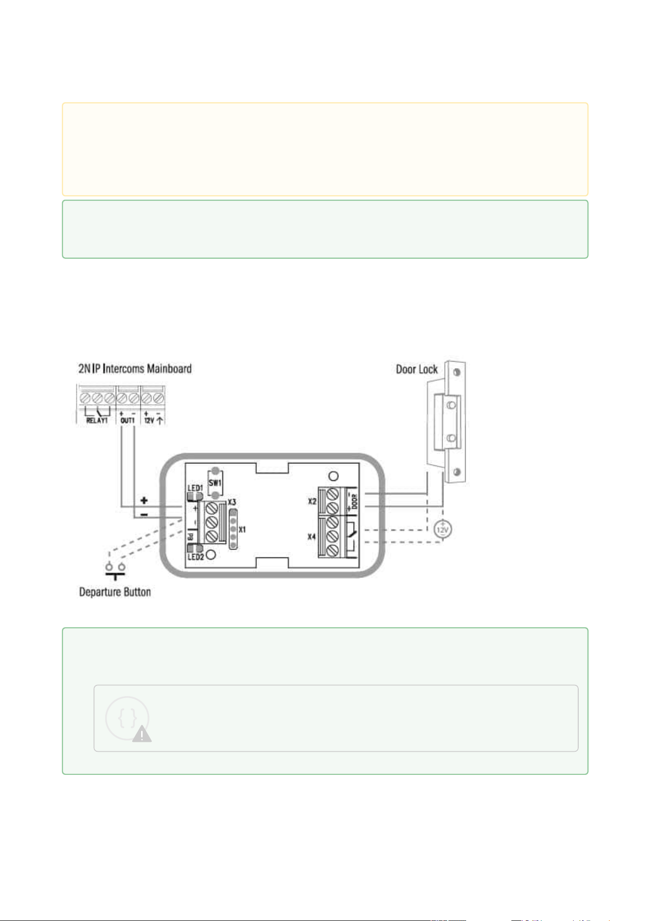
2N Access Unit Installation Manual
104 / 118
Connection:
Caution
In case of resetting the factory default settings on a device with a version of firmware
2.18 or higher, it is necessary to reprogram the
2N
®
IP Security Relay using the instructions above.
Tip
FAQ: 2N® IP Security Relay device description and use with 2N IP intercom
Tip
IP Intercom Security Relay Installation and Setup
Sorry, the widget is not supported in this export.
But you can reach it using the following URL:
https://www.youtube.com/watch?v=ardukvQzw5A

2N Access Unit Installation Manual
105 / 118
2.5 Mounting Completion
Mounting Completion
Check the connection of all wires and the RJ-45 plug to the pigtail (adapter) connected to the
motherboard.

2N Access Unit Installation Manual
106 / 118
Frame Mounting
Check the frame sealing before fitting the frame.
Version A
Screw the flush mounting frame in the upper and bottom parts.
Version B
Hang the wall mounting frame on the hook in the upper part and then screw it tight in the
bottom part.
•
Caution
Make sure that the terminals of all the unused connectors are tightened properly
to avoid sound vibrations.
•
•
•
Caution
Improper mounting may deteriorate the 2N Access Unit waterproofness. Water
infiltration may damage the electronic part.
Make sure that all the holes are filled with some waterproof material – the top part,
around the cables and the screws.
Use silicone or some other sealant to seal the box against the wall if uneven to
avoid water leakage and wall damping.
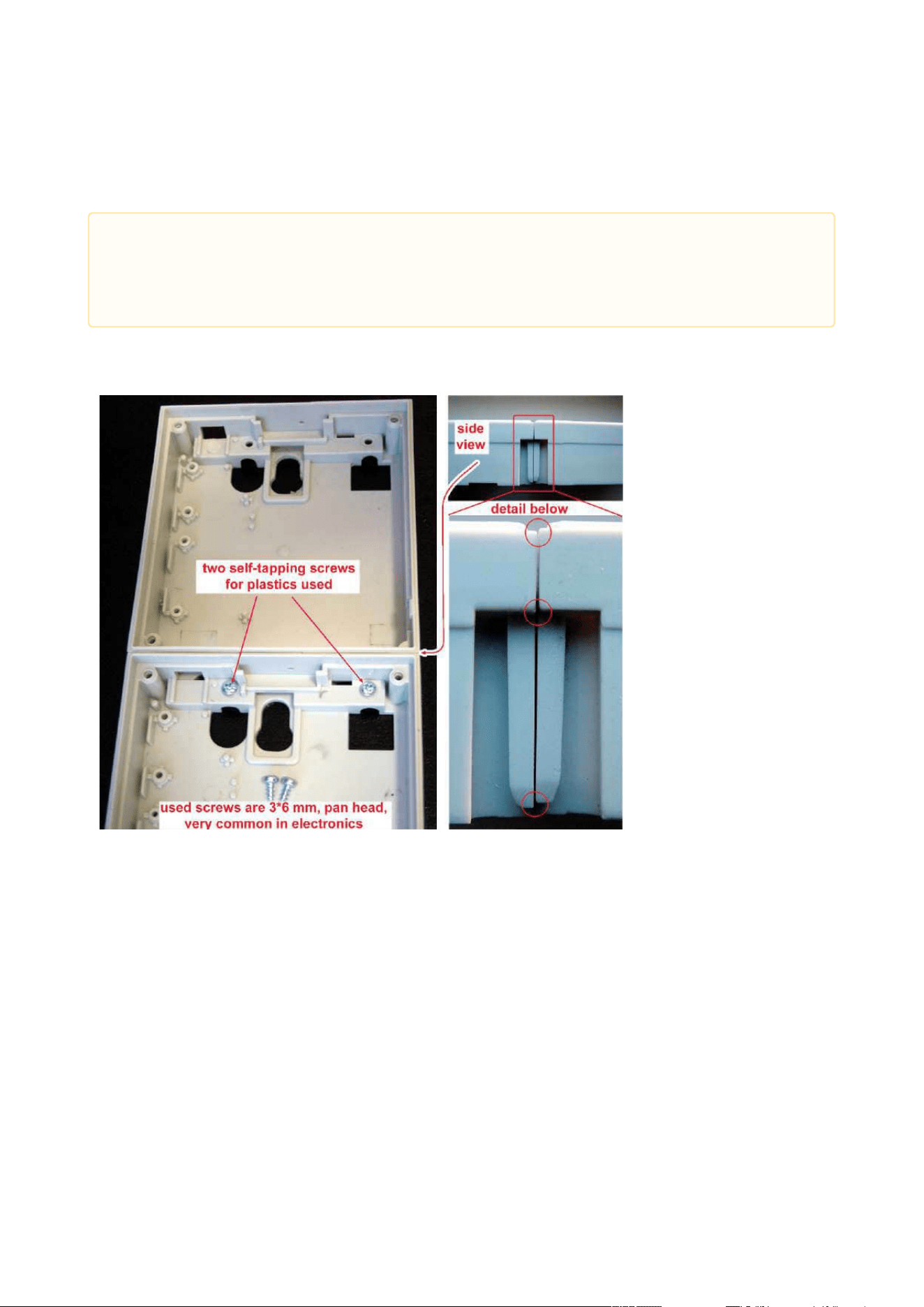
2N Access Unit Installation Manual
107 / 118
Most Frequent Mounting Errors
At first, mount the metal bolts, level the bases on an even surface and tighten the screws.
The examples in the figures below show incorrectly assembled bases. This happens, in
particular, where the screws are tightened first.
•
Caution
Make sure that the bases are levelled properly to avoid water leakage and
electronic damage.
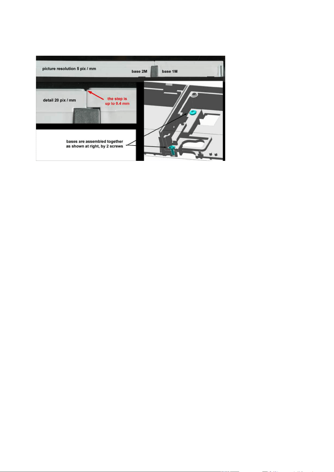
2N Access Unit Installation Manual
108 / 118

2N Access Unit Installation Manual
109 / 118
•
•
3. Maintenance
Cleaning
If used frequently, the device surface, the keypad in particular, gets dirty. Use a piece of soft
cloth moistened with clean water to clean the device. You are recommended to follow the
principles below while cleaning:
Do not use aggressive detergents (such as abrasives or strong disinfectants).
Clean the device in dry weather in order to make waste water evaporate quickly.
•
•
Warning
Prevent water from getting inside the access unit.
Do not use Alcohol-based cleaners.

2N Access Unit Installation Manual
110 / 118
•
•
•
•
•
•
•
•
•
•
•
•
•
•
•
•
•
•
•
•
•
•
•
•
•
•
•
•
•
•
•
4. Technical Parameters
Audio
Speaker:0.8 W / 8 Ω
Interface
Power supply:12 V ±15 % / 1 A
PoE:PoE 802.3af (Class 0–12.95 W)
LAN:10/100BASE-TX with Auto-MDIX, RJ-45
Recommended cabling:Cat-5e or higher
Supported protocols:DHCP opt. 66, SMTP, 802.1x, TFTP, HTTP, HTTPS, Syslog
Passive switch:make and break contact, up to 30 V / 1 A AC/DC
Active switch output:8 to 12 V DC according to power supply (PoE: 10 V; adapter: source
voltage minus 2 V), up to 600 mA
Tamper switchis part of the2NAccess Unit
Inputs: passive / active mode (−30 V to +30 V DC)
OFF = open or U
in
> 1.5 V
ON = short-circuit or U
in
< 1.5 V
RFID card reader
Frequency:13.56 MHz & 125 kHz
Supported 13.56 MHz cards(only card serial number is read):
ISO14443A (MIFARE DESFire)
PicoPass (HID iClass)
FeliCa
ST SR(IX)
2N
®
Mobile Key
HID SE ((Seos, iClass SE, MIFARE SE) valid for secured cards)
Supported 125 kHz cards:EM4100, EM4102
2N
®
IP Verso – Bluetooth module
Bluetooth 4.0 Compliant (Bluetooth Low Energy, BLE)
Security: asymmetric RSA-1024 and symmetric AES-128 encryption
RX sensitivity: up to −93 dBm
Range: adjustable (short ~ 0.5m, medium ~ 2m, long ~ up to 10m)
Power consumption: 20mA at 12V DC
Operational temperature range:−40°C ~ +60°C
Storage temperature range:−40°C ~ +70°C
Dimensions: 97 x 105 x 30mm
Compatible with 2N
®
IP Verso, 2N
®
LTE Verso and 2NAccess Unit
Mobile app. support: Android 6.0 Marshmallow and higher, iOS 12.0 and higher

2N Access Unit Installation Manual
111 / 118
•
•
•
•
•
•
•
•
•
•
•
•
•
•
•
•
•
•
•
•
•
•
•
Mechanical properties
Cover:robust zinc casting with surface finish(minor surface shade nuances are
acceptable)
91550XX – NICKEL
Material– Zamak 410– Zn95Al4Cu1
Surface treatment– Zn/Cu20/Ni25b max. 80 µm
91550XXB – BLACK
Material– Zamak 410– Zn95Al4Cu1
Surface treatment– Cataphoretic coating Black 30 µm, RAL 9004 –
Signalschwarz (colour is not guaranteed – it is cataphoretic)
Operating temperature:−40 °C to 60 °C
Operating relative humidity:10 % – 95 % (non-condensing)
Maximum altitude for intended use: 2000 m a.s.l.
Storage temperature:−40 °C to 70 °C
Dimensions:
Wall (surface) mounting frame:
1 module: 107 (W) x 130 (H) x 28 (D) mm
2 modules: 107 (W) x 234 (H) x 28 (D) mm
Flush mounting frame:
1 module: 130 (W) x 153 (H) x 5 (D) mm
2 modules: 130 (W) x 257 (H) x 5 (D) mm
Flush mounting box (minimum hole dimensions):
1 module: 108 (W) x 131 (H) x 45(D)mm
2 modules: 108 (W) x 238 (H) x 45 (D) mm
Weight:Max net weight: 2 kg / max. gross weight: 0.5 kg – based on configuration
Cover rating:IP54
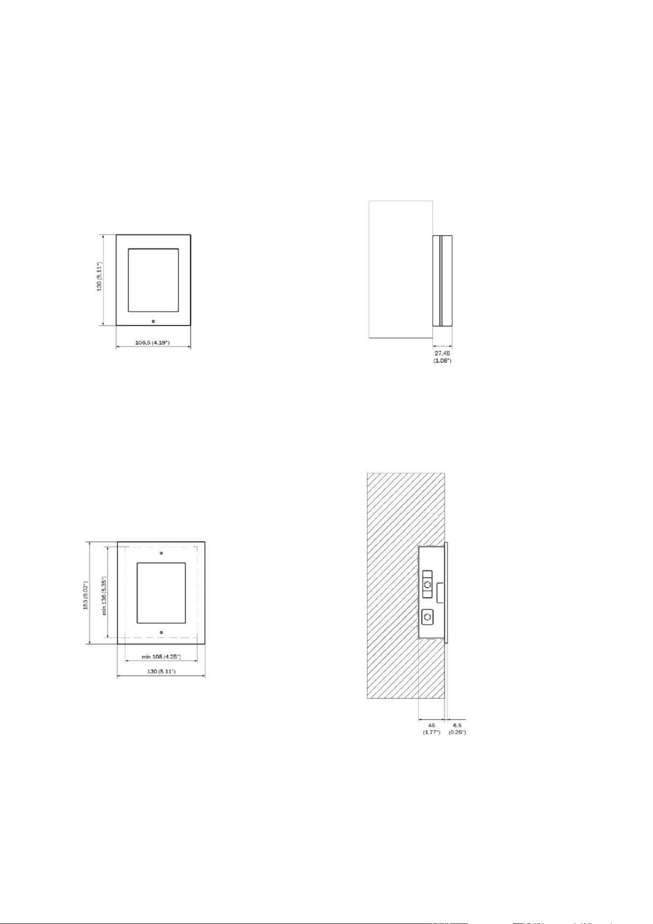
2N Access Unit Installation Manual
112 / 118
4.1 General drawings
Surface mounting
Flush mounting

2N Access Unit Installation Manual
113 / 118
•
•
•
•
•
•
•
•
•
•
•
5. Supplementary Information
Here is what you can find in this section:
5.1 Troubleshooting
5.2 Directives, Laws and Regulations
5.3 Other Countries' Legislation
5.4 General Instructions and Cautions
5.1 Troubleshooting
For the most frequently asked questions refer to faq.2n.cz.
5.2 Directives, Laws and Regulations
2N Access Unit conforms to the following directives and regulations:
2014/53/EU for radio equipment
2011/65/EU on the restriction of the use of certain hazardous substances in electrical and
electronic equipment
2012/19/EU on waste electrical and electronic equipment
Industry Canada
This Class A digital apparatus complies with Canadian ICES-003/NMB-003.
FCC
This equipment has been tested and found to comply with the limits for a Class A digital device,
pursuant to part 15 of the FCC Rules.
NOTE: These limits are designed to provide reasonable protection against harmful interference
in a residential installation. This equipment generates, uses and can radiate radio frequency
energy and, if not installed and used in accordance with the instructions, may cause harmful
interference to radio communications.
However, there is no guarantee that interference will not occur in a particular installation. If this
equipment does cause harmful interference to radio or television reception, which can be
determined by turning the equipment off and on, the user is encouraged to try to correct the
interference by one or more of the following measures:
Reorient or relocate the receiving antenna
Increase the separation between the equipment and receiver
Connect the equipment into an outlet on a circuit different from that to which the receiver
is connected
Consult the dealer or an experienced radio/TV technician for help

2N Access Unit Installation Manual
114 / 118
Changes or modifications to this unit not expressly approved by the party responsible for
compliance could void the user's authority to operate this equipment.

2N Access Unit Installation Manual
115 / 118
Caution
Warning
In order to ensure the full functionality and guaranteed performance, we strongly
recommend that the topicality of the product / device version in use be verified as early
as in the installation process. The customer hereby acknowledges that the product /
device can achieve the guaranteed performance and full functionality pursuant to the
manufacturer’s instructions only if the latest product / device version is used after
having been tested for full interoperability and not having been determined by the
manufacturer as incompatible with certain versions of other products, and only in
conformity with the manufacturer’s instructions, guidelines or recommendations and in
conjunction with suitable products and devices of other suppliers. The latest versions
are available at https://www.2n.com/cs_CZ/ or can be updated via the configuration
interface if the devices are adequately technically equipped. Should the customer use a
product / device version other than the latest one or a version determined by the
manufacturer as incompatible with certain versions of other products, or should the
customer use the product / device in contradiction to the manufacturer’s instructions,
guidelines or recommendations or in conjunction with unsuitable products / devices of
other suppliers, the customer is aware of and agrees with all functionality limitations of
such a product / device if any as well as with all consequences incurred as a result
thereof. Using a product / device version other than the latest one or a version
determined by the manufacturer as incompatible with certain versions of other
products, or using the product / device in contradiction to the manufacturer’s
instructions, guidelines or recommendations or in conjunction with unsuitable
products / devices of other suppliers, the customer agrees that the 2N
TELEKOMUNIKACE a.s. company shall not be held liable for any functionality limitation
of such a product or any damage, loss or injury related to this potential functionality
limitation.

2N Access Unit Installation Manual
116 / 118
5.3 Other Countries' Legislation
Thailand
5.4 General Instructions and Cautions
Please read this User Manual carefully before using the product. Follow all instructions and
recommendations included herein.
Any use of the product that is in contradiction with the instructions provided herein may result
in malfunction, damage or destruction of the product.
The manufacturer shall not be liable and responsible for any damage incurred as a result of a
use of the product other than that included herein, namely undue application and disobedience
of the recommendations and warnings in contradiction herewith.
Any use or connection of the product other than those included herein shall be considered
undue and the manufacturer shall not be liable for any consequences arisen as a result of such
misconduct.
Moreover, the manufacturer shall not be liable for any damage or destruction of the product
incurred as a result of misplacement, incompetent installation and/or undue operation and use
of the product in contradiction herewith.

2N Access Unit Installation Manual
117 / 118
The manufacturer assumes no responsibility for any malfunction, damage or destruction of the
product caused by incompetent replacement of parts or due to the use of reproduction parts or
components.
The manufacturer shall not be liable and responsible for any loss or damage incurred as a result
of a natural disaster or any other unfavourable natural condition.
The manufacturer shall not be held liable for any damage of the product arising during the
shipping thereof.
The manufacturer shall not make any warrant with regard to data loss or damage.
The manufacturer shall not be liable and responsible for any direct or indirect damage incurred
as a result of a use of the product in contradiction herewith or a failure of the product due to a
use in contradiction herewith.
All applicable legal regulations concerning the product installation and use as well as provisions
of technical standards on electric installations have to be obeyed. The manufacturer shall not be
liable and responsible for damage or destruction of the product or damage incurred by the
consumer in case the product is used and handled contrary to the said regulations and
provisions.
The consumer shall, at its own expense, obtain software protection of the product. The
manufacturer shall not be held liable and responsible for any damage incurred as a result of the
use of deficient or substandard security software.
The consumer shall, without delay, change the access password for the product after
installation. The manufacturer shall not be held liable or responsible for any damage incurred by
the consumer in connection with the use of the original password.
The manufacturer also assumes no responsibility for additional costs incurred by the consumer
as a result of making calls using a line with an increased tariff.
Electric Waste and Used Battery Pack Handling
Do not place used electric devices and battery packs into municipal waste containers. An undue
disposal thereof might impair the environment!
Deliver your expired electric appliances and battery packs removed from them to dedicated
dumpsites or containers or give them back to the dealer or manufacturer for environmental-
friendly disposal. The dealer or manufacturer shall take the product back free of charge and
without requiring another purchase. Make sure that the devices to be disposed of are complete.
Do not throw battery packs into fire. Battery packs may not be taken into parts or short-circuited
either.

Instalační manuál 2N Access Unit
118 / 118