Integration Manual
MUF

2
I.
Table of Contents
II.
Overview ............................................................................................................................. 3
III.
Composition .................................................................................................................... 4
IMPINJ E710 Tranceiver ......................................................................................................... 4
Directional coupler ................................................................................................................ 4
Host Controller ....................................................................................................................... 5
IV.
RF Operation (MUF Core Module) ................................................................................ 5
V.
Specifications ...................................................................................................................... 6
FCC / ISED (IC) Regulatory Statements ................................................................................ 6
FCC Statement
.................................................................................................................
6
FCC Radiations Exposure Statement ............................................................................... 7
ISED (IC) Canada Statement
...........................................................................................
7
ISED Radiation Exposure Statement ................................................................................ 7
Integration Statement ........................................................................................................ 7

3
II.
Overview
The MUF V2 module serves as the core radio frequency (RF) engine embedded across all
STid UHF RFID reader products. It operates within the 860–930 MHz frequency band,
ensuring compatibility with global UHF RFID standards and enabling reliable long-range
identification performance.
Designed exclusively for internal integration, the MUF V2 is a proprietary module and is
not intended for standalone commercialization or external distribution. It is fully
optimized to meet the performance, compliance, and robustness requirements of STid’s
UHF reader portfolio.
The module provides high-efficiency RF signal processing, stable communication
capabilities, and seamless integration within STid hardware architectures, making it a
critical component in delivering consistent and high-performance RFID reading
solutions.
4
III.
Composition
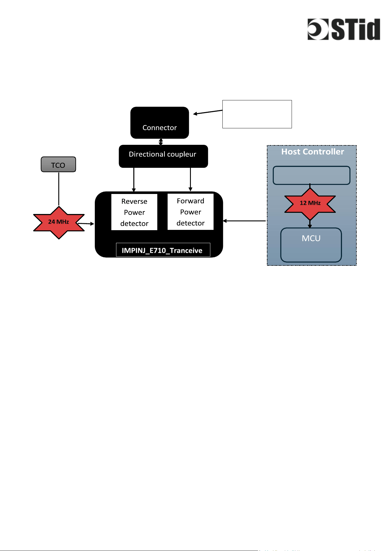
IMPINJ E710 Tranceiver
The reader chip implements direct conversation receiver architecture, and operate in
the worldwide UHF industrial band. It contain all RF and baseband blocks to interrogate
and receive data from compatible UHF RFID tags, and an integrated microcontroller
with embedded firmware providing the GS1 UHF Gen2 RAIN protocol as a pre-integrated
feature.
The Impinj E710 reader chip contain power detectors connected to the RX and LO pins,
allowing measurement of forward (transmit) power on the LO pin and reverse power on
the RX pin. These power detectors convert the RF power level at the RX and LO pins into
analog voltages, which are measured by the Auxiliary ADC inside the reader chip.
Directional coupler
Our MUF radio transceiver board use a directional coupler to isolate the transmit (TX)
signal and the receive (RX) signal, to reduce self-jammer, and to sample a local
oscillator (LO) for use in self-jammer cancellation, for forward power measurement and
down sampling of the received signal
MMCX
Crystal for MCU
STM32
Input and output
RF signal

5
Host Controller
The Host Controller is a microcontroller responsible for managing communication with
the Impinj RF reader IC and controlling its operational behavior. It acts as the central
interface between the system firmware and the RF front-end, issuing commands and
handling data exchange required for RFID operations.
Communication between the Host Controller and the Impinj reader chip is implemented
via a Serial Peripheral Interface (SPI). In this configuration, the Impinj device operates as
an SPI slave, while the Host Controller functions as the master, initiating all transactions
and controlling data flow. Additional digital lines are used to synchronize and manage
SPI communication, ensuring reliable and deterministic operation.
The interface also includes configurable Digital Input/Output (GPIO) pins. These pins
can be programmed as inputs or outputs depending on system requirements and are
used to support control, status monitoring, and hardware-level signaling between the
Host Controller and the RF subsystem.
IV.
RF Operation (MUF Core Module)
All radio frequency (RF) operations within the STid UHF RFID reader products are fully
managed and executed by the MUF module, which serves as the core RF engine of the
system.
Upon power-up, the MUF module automatically performs an internal tuning and
calibration procedure within its integrated RF transceiver. This process dynamically
adjusts internal capacitive and resistive elements of the RF front-end to optimize
impedance matching at the selected carrier frequency. As a result, the MUF ensures
optimal receiver sensitivity and consistent bandwidth performance across the entire
operating frequency range (typically 902 MHz to 928 MHz, depending on regional
configuration).
This initial calibration is designed to guarantee proper operation across all frequency
hopping channels. In addition, at each RF activation, the MUF continuously monitors
matching conditions and autonomously readjusts its internal network if necessary,
ensuring stable and reliable RF performance without external intervention.
The MUF module integrates a shared local oscillator for both transmission and reception
paths, generated by an internal phase-locked loop (PLL) frequency synthesizer. This
architecture inherently synchronizes frequency changes during hopping sequences,
maintaining coherent operation between transmitter and receiver across all channels.

6
The receiver chain, fully embedded within the MUF, consists of an RF front-end followed
by a demodulation stage specifically designed to detect and process backscattered
signals from UHF RFID tags.
This high level of integration within the MUF module ensures consistent RF performance,
simplifies system design, and supports compliance with regulatory and certification
requirements.
V.
Specifications
Item
Unit
Specification
Min
Typ
Max
Frequency range
MHz
865
928
Protocole « Air interface »
EPC Global UHF Class 1 Gen 2 v2 / ISO 18000-63
Sensor
Temperature sensor
DC Power
V
5.5
Host Interface
SPI
RF Output
dBm
15
32.6
RF IO Impedance
Ω
50
Operating temperature
°C
-20
+60
Dimensions
mm
93x60.5x13.1
FCC / ISED (IC) Regulatory Statements
FCC Statement
This equipment contains an RF module (MUF V2) that has been certified in accordance
with Part 15 of the FCC Rules.
This device complies with Part 15 of the FCC Rules. Operation is subject to the following
two conditions:
(1)
This device may not cause harmful interference, and
(2)
This device must accept any interference received, including interference that may
cause undesired operation.

7
The MUF V2 module is intended for integration into STid UHF RFID reader products only
and is not marketed or sold as a standalone device. Final host products incorporating
this module are required to comply with all applicable FCC regulations.
Any changes or modifications not expressly approved by STid could void the user’s
authority to operate the equipment.
FCC Radiations Exposure Statement
This equipment complies with FCC radiation exposure limits set forth for an
uncontrolled environment.
The device must be installed and operated with a minimum distance of
2
0 cm
between the radiator and the user or nearby persons.
The host integrator is responsible for ensuring that the final product maintains
compliance with applicable RF exposure requirements.
ISED (IC) Canada Statement
This device contains licence-exempt transmitter(s)/receiver(s) that comply with
Innovation, Science and Economic Development Canada’s licence-exempt RSS(s).
Operation is subject to the following two conditions:
(1)
This device may not cause interference, and
(2)
This device must accept any interference, including interference that may cause
undesired operation of the device.
L’émetteur/récepteur exempt de licence contenu dans le présent appareil est
conforme aux CNR d’Innovation, Sciences et Développement économique Canada
applicables aux appareils radio exempts de licence. L’exploitation est autorisée aux
deux conditions suivantes :
(1) L’appareil ne doit pas produire de brouillage ;
(2) L’appareil doit accepter tout brouillage radioélectrique subi, même si le brouillage
est susceptible d’en compromettre le fonctionnement.
ISED Radiation Exposure Statement
This equipment complies with ISED radiation exposure limits set forth for an
uncontrolled environment.
This equipment should be installed and operated with a minimum distance of
2
0 cm
between the radiator and the user.

8
OEM integration Requirements
General Conditions
This device is intended only for OEM integrators under the following conditions:
• The MUF module must be installed such that a minimum separation distance of 20 cm is
maintained between the radiator (antenna) and body.
• The MUF module is limited to installation in fixed applications.
• The transmitter module must not be co-located or operating in conjunction with any
other antenna or transmitter, except in accordance with FCC multi-transmitter product
procedures.
• The MUF module must only be used with the included onboard antenna or antenna
approved by the manufacturer (STiD). Use of unauthorized antenna is strictly prohibited.
• The OEM integrator is responsible for ensuring that the end-user manual does not
contain instructions on how to install or remove the RF module.
• The OEM integrator must include the required FCC an ISED statements (per FCC Part
15.19 and 15.21 and ISED RSS-GEN §4) in the user manual of the host device.
• The user manual for the host product must clearly indicate the operating requirements
and conditions to ensure compliance with current FCC and ISED RF exposure guidelines.
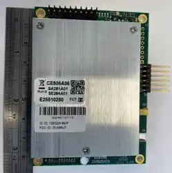
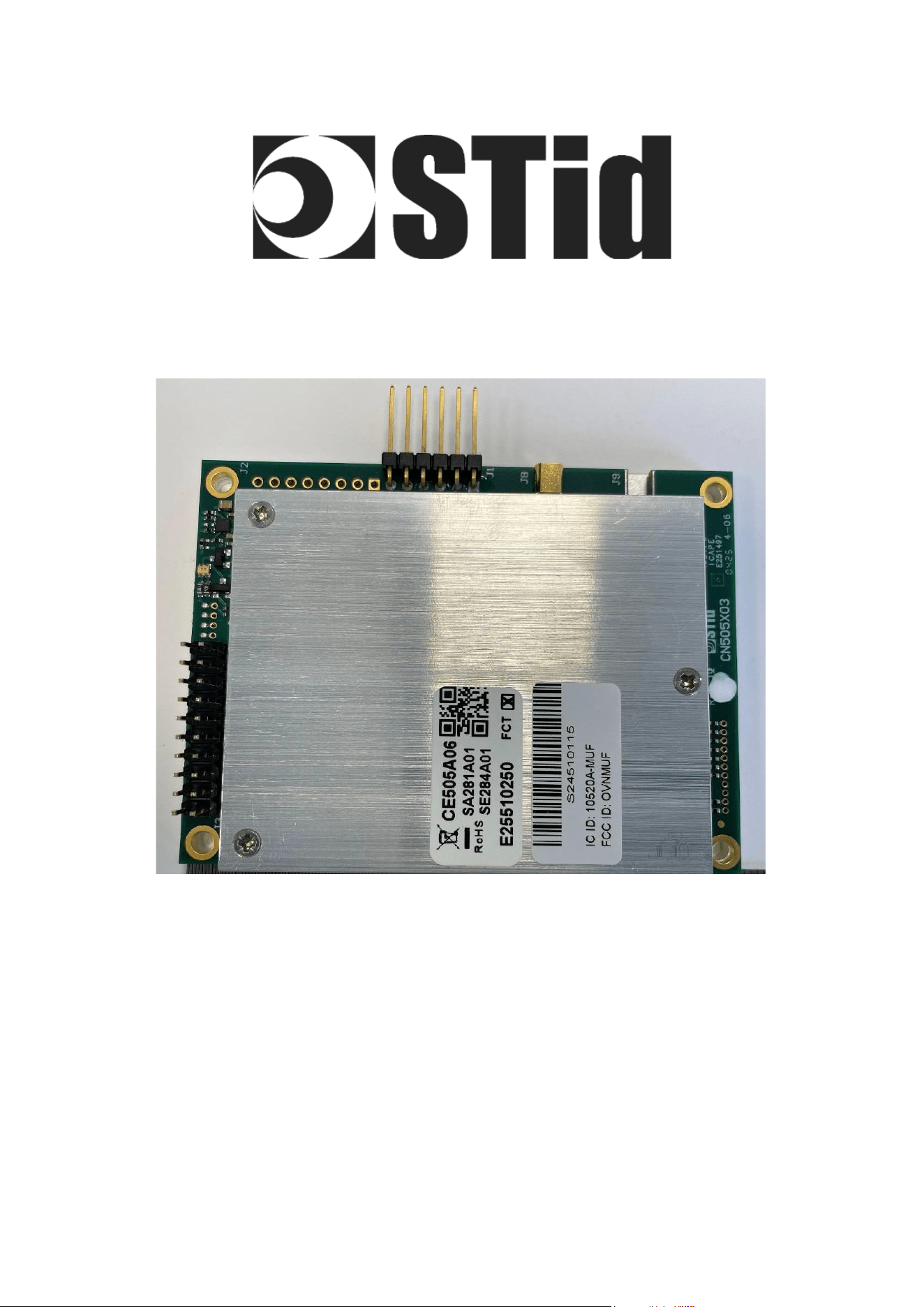
Labeling Requirements
The module is labeled with its own FCC ID and IC ID. If the FCC ID and IC ID are not visible when
the module is installed inside another device, the outside of the device must also display a label
referring to the enclosed module:
Example:
”Contains FCC ID: OVNMUF” and “Contains IC: 10520A-MUF”.
To satisfy FCC exterior labeling requirements, the final product must include the above
statement in a visible location.
Additional Compliance
• The OEM integrator is still responsible for testing the final product for any additional
compliance requirements (e.g., digital device emissions under Part 15B and RSS-GEN).
• The integration of the MUF module into a host device will require a Class II Permissive
Change application with the FCC rules and a Class IV Permissive Change application with
ISED rules.