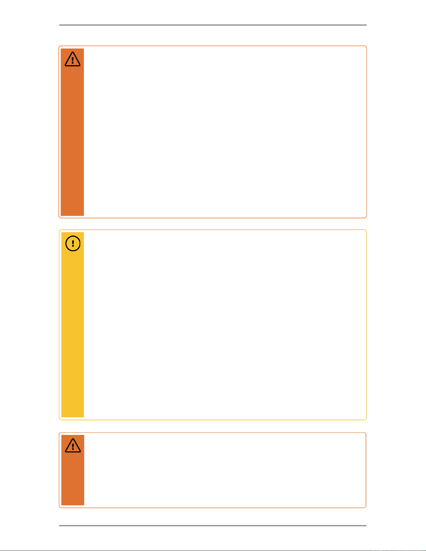
CAUTION
Uniform Plumbing Code Requirements
An indirect fired water heater that incorporates a single wall heat exchanger shall be in
accordance with the following requirements:
• The heat transfer medium shall be either potable water or contain fluids recognized as safe
by the Food and Drug Administration (FDA) as food grade.
• The maximum operating pressure of the heat exchanger shall not exceed the maximum
operating pressure of the potable water supply.
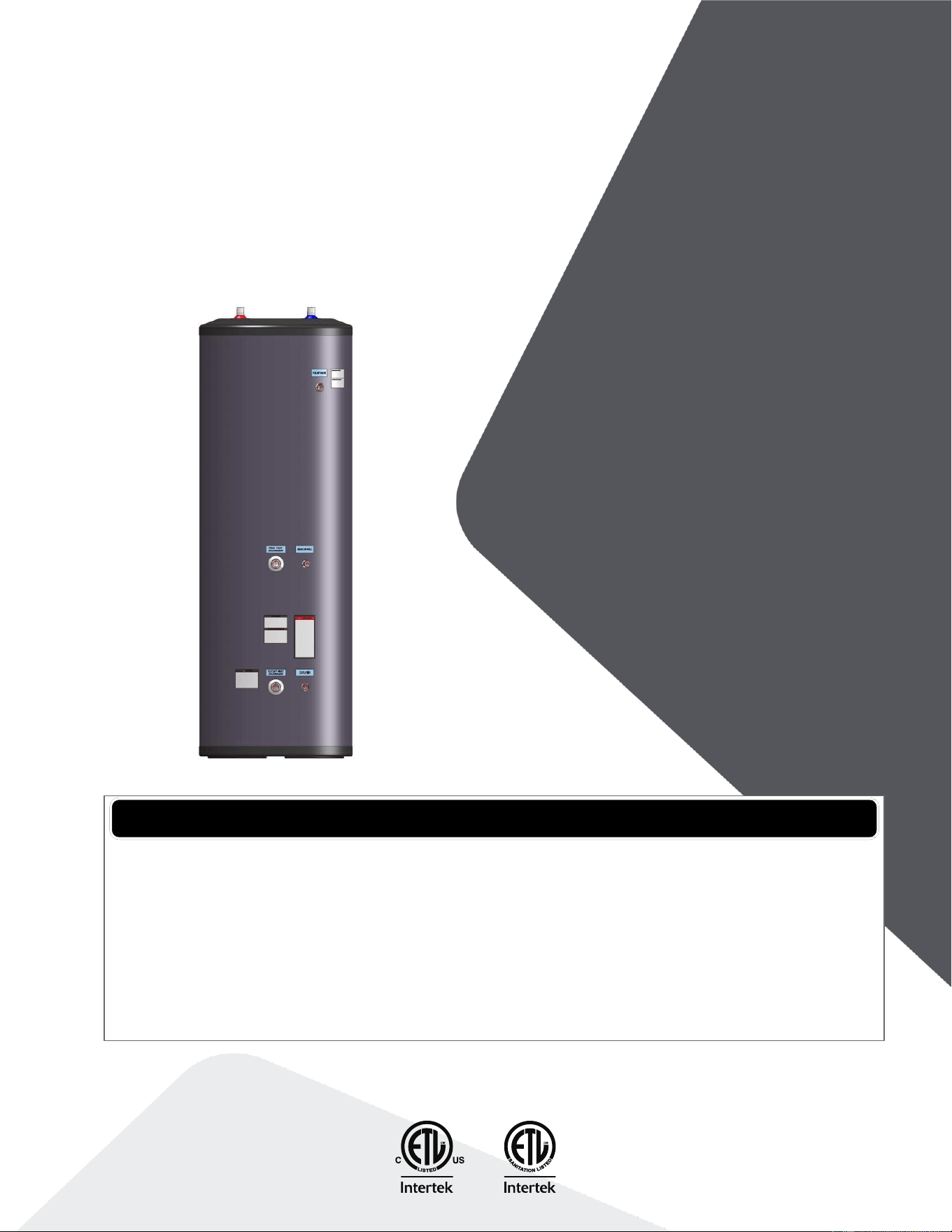
INSTALLATION &
OPERATING MANUAL
Indirect Water Heaters
30
80-Max
40 119-Max
55
65
80
119

Intentionally left empty

3
Contents
1.0 Safety information ....................................................................................................... 5
Manual safety markings ............................................................................................................ 5
Important safety instructions ..................................................................................................... 5
2.0 Specifications ............................................................................................................... 8
2.1 Dimensions ....................................................................................................................... 10
2.2 Coil pressure drop ............................................................................................................. 13
2.3 Temperature & pressure relief valve requirements ............................................................ 13
3.0 Introduction ................................................................................................................ 14
3.1 Included components ........................................................................................................ 14
3.2 Conformity ......................................................................................................................... 14
3.3 Standards .......................................................................................................................... 14
4.0 Before installation ...................................................................................................... 15
4.1 Installation checklist .......................................................................................................... 15
4.2 System zone control .......................................................................................................... 16
4.3 DHW priority options ......................................................................................................... 16
4.4 Locating the indirect water heater ..................................................................................... 17
4.5 Temperature and pressure relief valve ............................................................................. 18
4.6 Additional recommended components .............................................................................. 19
4.7 Removing an existing water heater .................................................................................. 19
4.8 Water quality ..................................................................................................................... 20
5.0 Piping .......................................................................................................................... 21
5.1 Domestic piping ................................................................................................................. 21
5.2 Boiler piping ...................................................................................................................... 22
5.3 Zone circulator system ...................................................................................................... 22
5.4 Zone valve system ............................................................................................................ 23
6.0 Electrical ..................................................................................................................... 24
6.1 Temperature sensor .......................................................................................................... 24
6.2 Aquastat ............................................................................................................................ 25
7.0 Operation ....................................................................................................................... 26
7.1 Important terms ................................................................................................................. 26
7.2 Start-up.............................................................................................................................. 26
7.3 DHW temperature adjustment ........................................................................................... 26
8.0 Maintenance .................................................................................................................. 28
8.1 Chemical cleaning of the heating coil ............................................................................... 29

4
Section: Contents
9.0 Troubleshooting ......................................................................................................... 30
10.0 Piping Diagrams ......................................................................................................... 32
11.0 Replacement Parts ..................................................................................................... 35
5
1.0 Safety information
Manual safety markings
Important safety instructions
Failure to read and comply with all instructions and applicable national and local codes may result
in hazardous conditions that could result in property damage and injury to occupants, and in
extreme cases to death. Keep instructions near the indirect water heater for future reference.
When using electrical appliances, follow safety precautions to reduce the risk of fire, electric shock,
or injury to persons, including:
Install or locate the indirect water heater only in accordance with the provided installation
instructions.
Use the indirect water heater only for its intended use as described in this manual.
As with any appliance, close supervision is necessary when used by children.
Do not operate the indirect water heater if it is not working properly, or if it has been damaged
or dropped.
Installation, start-up, and servicing of this indirect water heater must be done with care and
attention, and should only be performed by competent, qualified, licensed, and trained
plumbing and heating technicians. Contact your nearest authorized service facility for
examination, repair, or adjustment.
Danger
Points out an immediate
hazardous situation that must
be avoided to prevent serious
injury or death.
Caution
Points out a potential hazardous
situation that must be avoided to
prevent possible moderate
injury and/or property damage.
Warning
Points out a potential hazardous
situation that must be avoided to
prevent serious injury or death.
Note
Points out installation, maintenance,
and operational notes to enhance
efficiency, longevity, and proper
operation of your water heater.
6
Section: Safety information
Danger
Do not store or use gasoline or other flammable vapors or liquids in the vicinity of this or
any other appliance. If you smell gas vapors, do not try to operate any appliance - do not
touch any electrical switch or use any phone in the building. Immediately, call the gas
supplier from a phone located remotely. Follow the gas supplier’s instructions, or if the
supplier is unavailable, contact the fire department.
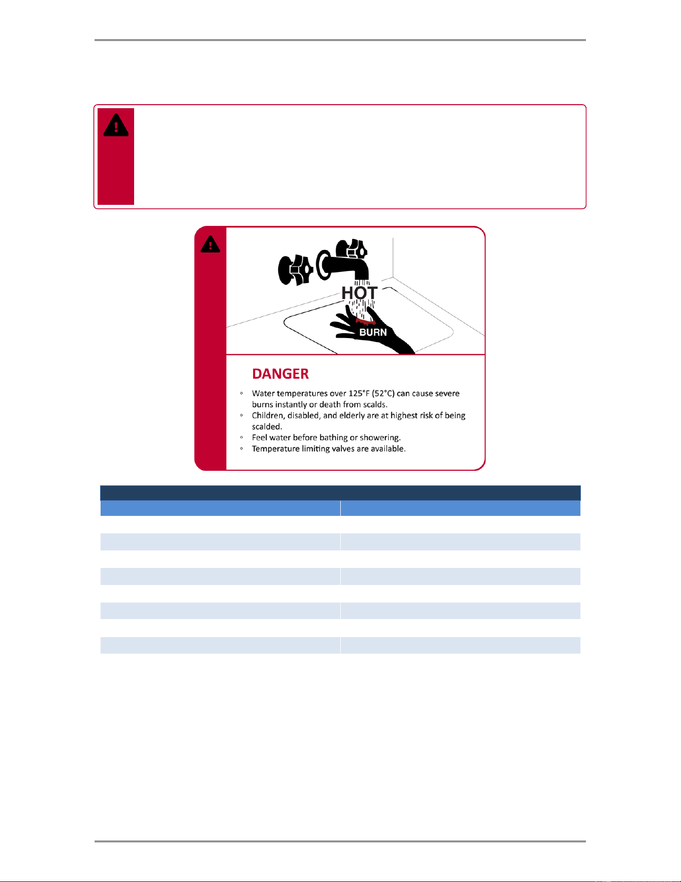
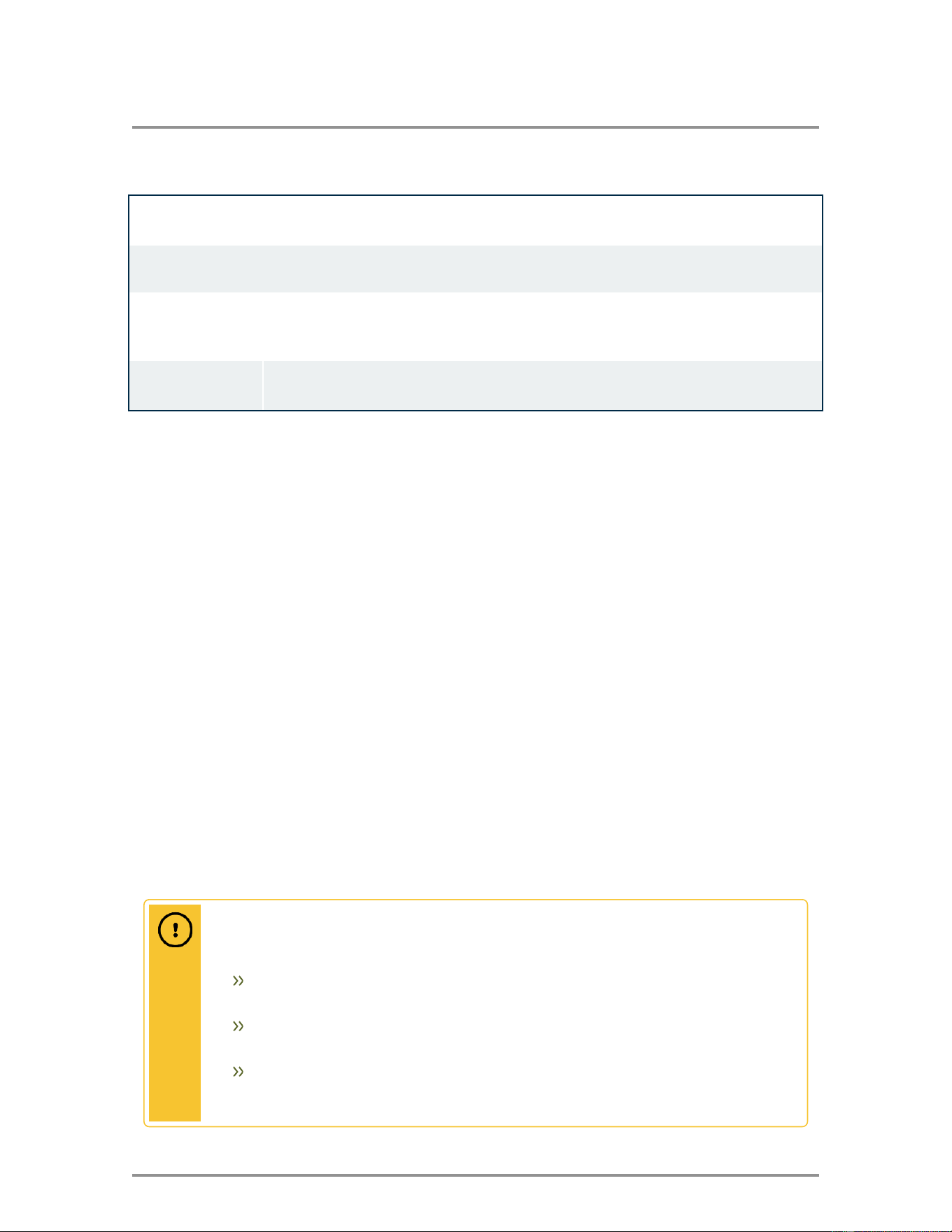
TIME/TEMPERATURE RELATIONSHIP IN SCALDS
WATER TEMPERATURE
TIME TO PRODUCE A SERIOUS BURN
120°F (49°C)
More than 5 minutes
125°F (52°C)
1 ½ to 2 minutes
130°F (54°C)
About 30 seconds
135°F (57°C)
About 10 seconds
140°F (60°C)
Less than 5 seconds
145°F (63°C)
Less than 3 seconds
150°F (66°C)
About 1 ½ seconds
155°F (68°C)
About 1 second
Table courtesy of Shriners Burn Institute
7
Important safety instructions
Caution
To reduce the risk of excessive temperatures and pressures in this indirect water heater,
install temperature and pressure protective equipment required by local codes, but no
less than a combination temperature/pressure relief valve certified by a nationally
recognized testing laboratory that maintains periodic inspection of production of listed
equipment or materials, as meeting the requirements for Relief Valves for Hot Water
Supply Systems, ANSI Z21.22/CSA 4.4 latest edition.
This relief valve must be marked with a maximum set pressure not to exceed the marked
working pressure of the indirect water heater. Install the relief valve into the tapping
provided and marked for this purpose in the indirect water heater and orient it or provide
tubing so that any discharge from the valve will exit only within 6 inches above a suitable
drain. The discharge opening must not be blocked or reduced in size under any
circumstances. The heat transfer medium must be water or other non-toxic fluid having a
toxicity rating or class of 1, as listed in clinical Toxicology of Commercial Products, latest
edition.
Installation, start-up and servicing of boilers and indirect water heaters must be done with
due care and attention, and should only be performed by competent, qualified, licensed, and
trained heating technicians.
Warning
Improper installation, adjustment, alteration, service, or maintenance can cause property
damage, personal injury, or loss of life. Read and understand the entire manual before
attempting installation, start-up, operation, or service. Installation and service must be
performed only by an experienced, skilled installer or service agency.
The indirect water heater contains very hot water under high pressure. Do not unscrew
any pipe fittings or attempt to disconnect any components of this indirect water heater
without positively ensuring that the water is cool and has no pressure. Always wear
protective clothing and equipment when installing, starting up or servicing this indirect
water heater to prevent scalding injuries. Do not rely on the temperature and pressure
gauges to determine the temperature and pressure of the indirect water heater. This
indirect water heater contains components that become very hot when the boiler is
operating. Do not touch any components unless they are cool.
Failure to follow all instructions in the proper order can cause personal injury or death.
Read all instructions, including all those contained in component manufacturers’ manuals
before installing, starting up, operating, maintaining, or servicing the indirect water heater.
Warning
The boiler supplying hot water to the indirect hot water heater coil must be equipped with
an automatic shutoff system actuated before the outlet water temperature exceeds 250°F
(121°C). The automatic shutoff system must be of the manual reset type and comply with
one of the following: Standard for Automatic Gas Shutoff Devices for Hot Water Supply
Systems, ANSI Z21.87/CSA 4.6, or the Standard for Limit Controls, UL353 or CSA C22.2
No.24.
8
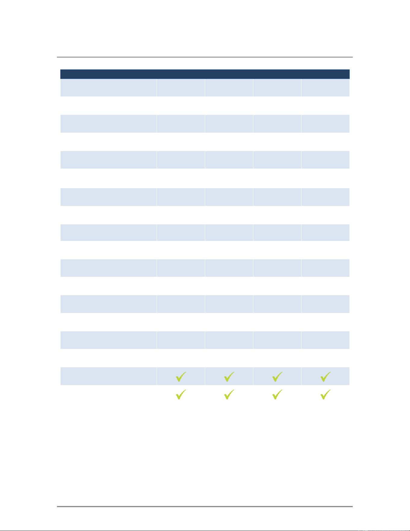
2.0 Specifications
Specification
30
40
55
65
Diameter
Inches (cm)
20.1
(51.1)
21.8
(55.5)
21.8
(55.5)
23.8
(60.4)
Height
Inches (cm)
39.6
(100.6)
46.9
(119.2)
62.8
(159.4)
59.5
(151.0)
Gross DHW Volume
Gallons
26.8
40.1
56.8
66.6
Net DHW Volume
Gallons
25.7
38.9
55.1
64.9
Max. Operating Pressure
PSI
150
150
150
150
Max. DHW Temperature
°F (°C)
180
(82)
180
(82)
180
(82)
180
(82)
Weight
Pounds (kg)
44
(20)
58
(27)
83
(38)
96
(44)
Shipping Weight
Pounds (kg)
51
(23)
66
(30)
92
(42)
105
(48)
Domestic Connection Size
Inches
¾
¾
¾
¾
Boiler Connection Size
Inches
1
1
1
1
First Hour Delivery*
Gallons / Hour
159
185
240
285
Continuous Draw*
Gallons / Hour
137
154
193
230
Boiler Output Required*
BTU / Hour
88,000
98,000
123,000
146,500
Heating Coil Flow Rate*
GPM
8
8
8
13
Heating Coil Pressure Drop*
Feet of Head
3.0
2.5
3.3
8.2
Heating Coil Surface Area
Ft
2
(m
2
)
6.9
(0.64)
8
(0.74)
10.7
(0.99)
11.1
(1.03)
Certified – Water Heater
Certified – Low Lead
Table 1 30, 40, 55, 65 Models
*Based on 180°F boiler supply, 135° DHW and 58°F entering cold water
9
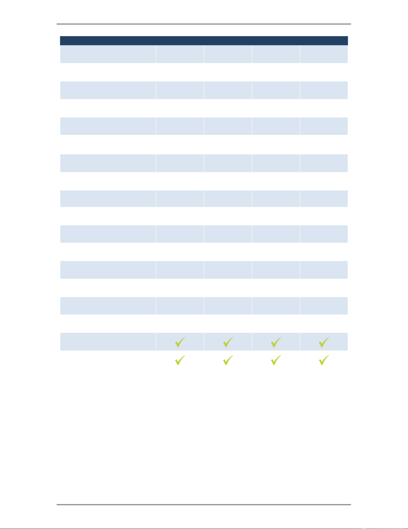
Specifications
Specification
80
119
80-Max
119-Max
Diameter
Inches (cm)
23.8
(60.4)
28.9
(73.4)
23.8
(60.4)
28.9
(73.4)
Height
Inches (cm)
69.9
(177.6)
65.8
(167.2)
69.9
(177.6)
65.8
(167.2)
Gross DHW Volume
Gallons
80.2
115
80.2
115
Net DHW Volume
Gallons
78.0
111.8
75.3
110
Max. Operating Pressure
PSI
150
150
150
150
Max. DHW Temperature
°F (°C)
180
(82)
180
(82)
180
(82)
180
(82)
Weight
Pounds (kg)
107
(48)
143
(65)
130
(59)
166
(76)
Shipping Weight
Pounds (kg)
118
(53)
155
(71)
141
(64)
178
(81)
Domestic Connection Size
Inches
1
1 ½
1 ½
1 ½
Boiler Connection Size
Inches
1
1 ½
1 ½
1 ½
First Hour Delivery*
Gallons / Hour
345
445
484
625
Continuous Draw*
Gallons / Hour
279
350
428
537
Boiler Output Required*
BTU / Hour
178,000
224,000
273,000
343,000
Heating Coil Flow Rate*
GPM
13
15
13
25
Heating Coil Pressure Drop*
Feet of Head
10.5
8.8
7.2
28.0
Heating Coil Surface Area
Ft
2
(m
2
)
14.2
(1.32)
18.5
(1.72)
26.4
(2.45)
27.6
(2.56)
Certified – Water Heater
Certified – Low Lead
Table 2 80, 119, 80-Max, 119-Max Models
* Based on 180°F boiler supply, 135° DHW and 58°F entering cold water
10
Section: Specifications
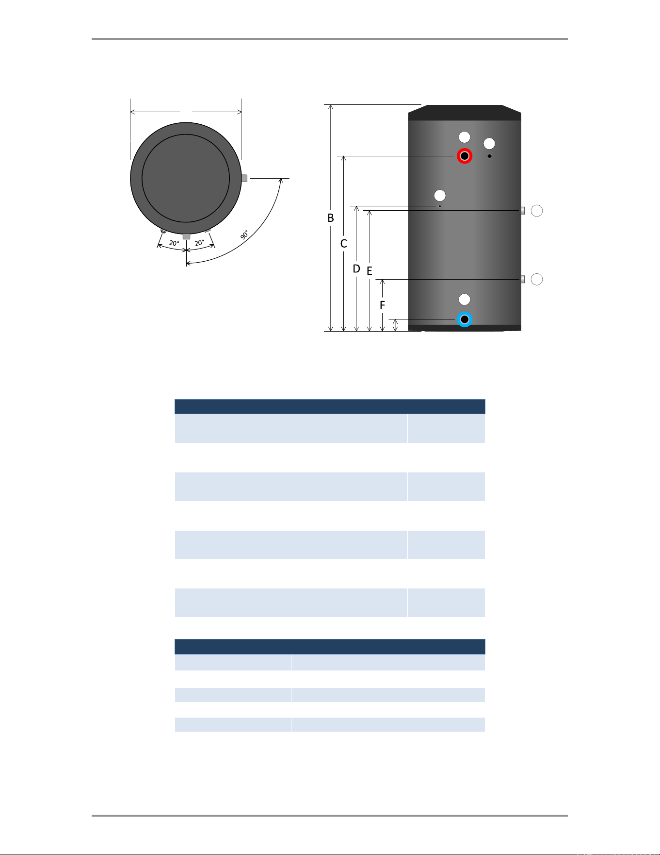
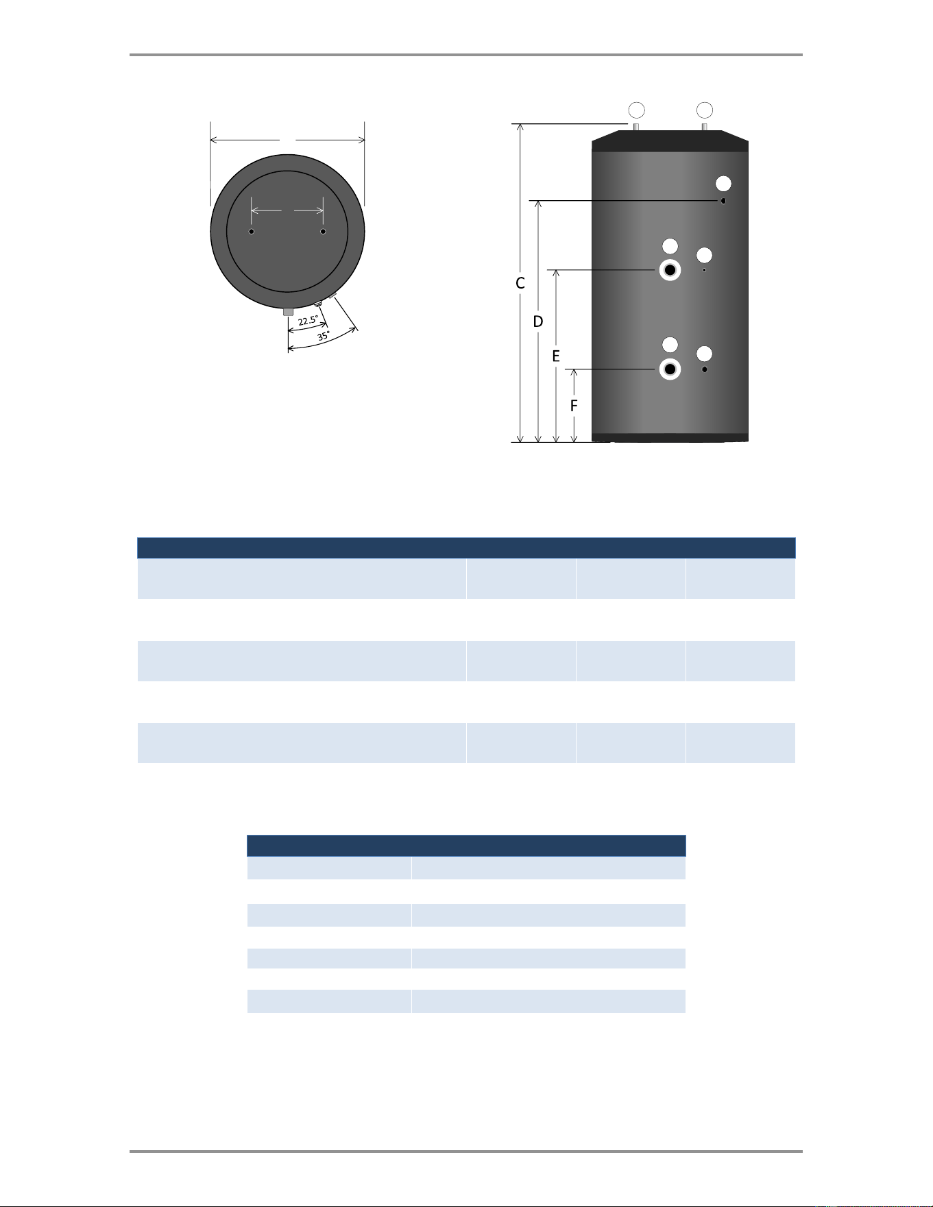
2.1 Dimensions
4
5
A
3
G
1
2
6
Figure 1 Indirect water heater dimensions - 30
Dimension
30
A = Diameter
Inches (cm)
20.1
(51.1)
B = Height
Inches (cm)
39.6
(100.6)
C = DHW Outlet & Relief Valve
Inches (cm)
30.9
(78.5)
D = Sensor / Aquastat Well
Inches (cm)
22.4
(57.0)
E = Boiler Supply
Inches (cm)
22
(56.0)
F = Boiler Return
Inches (cm)
9.5
(24.0)
G = DHW Inlet
Inches (cm)
2.2
(5.5)
Legend
30
1
DHW Outlet (¾” M)
2
T & P Relief Valve (¾” F)
3
Sensor / Aquastat Well
4
Boiler Supply (1” M)
5
Boiler Return (1” M)
6
DHW Inlet (¾” M)
11
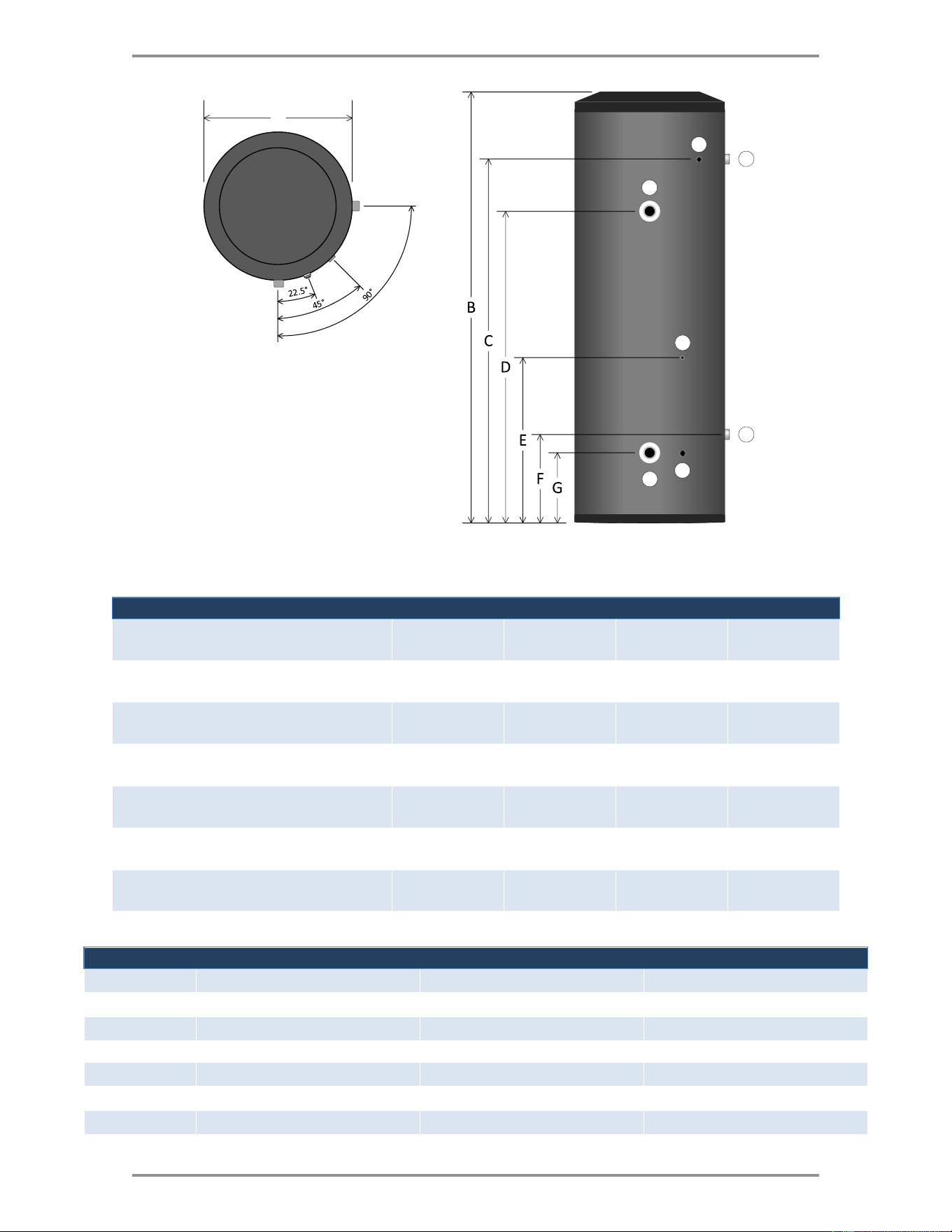
Dimensions
21
3
4
5
6
7
A
B
Figure 2 Indirect water heater dimensions - 40, 55, 65
Dimension
40
55
65
A = Diameter
Inches (cm)
21.8
(55.5)
21.8
(55.5)
23.8
(60.4)
B = DHW Inlet & Outlet Center to Center
Inches (cm)
10.1
(25.6)
10.1
(25.6)
10.1
(25.6)
C = Height
Inches (cm)
46.9
(119.2)
62.8
(159.4)
59.5
(151.0)
D = Relief Valve
Inches (cm)
37
(93.9)
52.8
(134.1)
50.1
(127.2)
E = Boiler Supply & Sensor / Aquastat Well
Inches (cm)
23.6
(59.9)
27.7
(70.4)
26.1
(66.2)
F = Boiler Return & Drain
Inches (cm)
10.2
(25.9)
10.2
(25.9)
9.9
(25.2)
Legend
40, 55, 65
1
DHW Outlet (¾” M)
2
DHW Inlet (¾” M)
3
T & P Relief Valve (¾” F)
4
Boiler Supply (1” M)
5
Sensor / Aquastat Well
6
Boiler Return (1” M)
7
DHW Drain (½” F)
12
Section: Specifications
2
7
A
1
3
4
5
6
Figure 3 Indirect water heater dimensions - 80, 119, 80-Max, 119-Max
Dimension
80
119
80-Max
119-Max
A = Diameter
Inches (cm)
23.8
(60.4)
28.9
(73.4)
23.8
(60.4)
28.9
(73.4)
B = Height
Inches (cm)
69.9
(177.6)
65.8
(167.2)
69.9
(177.6)
65.8
(167.2)
C = DHW Outlet & Relief Valve
Inches (cm)
60.5
(153.7)
53.2
(135.2)
60.5
(153.7)
53.0
(134.7)
D = Boiler Supply
Inches (cm)
30.0
(76.2)
31.7
(80.5)
51.7
(131.2)
42.5
(107.9)
E = Sensor / Aquastat Well
Inches (cm)
30.0
(76.2)
31.7
(80.5)
26.3
(66.7)
34.0
(86.2)
F = DHW Inlet
Inches (cm)
12.1
(30.7)
13.9
(35.2)
12.5
(31.7)
13.9
(35.2)
G = Boiler Return & Drain
Inches (cm)
9.9
(25.2)
11.5
(29.2)
9.9
(25.2)
11.5
(29.2)
Legend
80
80-Max
119, 119-Max
1
T & P Relief Valve (¾” F)
T & P Relief Valve (¾” F)
T & P Relief Valve (1” F)
2
DHW Outlet (1” M)
DHW Outlet (1½” M)
DHW Outlet (1½” M)
3
Boiler Supply (1” M)
Boiler Supply (1½” M)
Boiler Supply (1½” M)
4
Sensor / Aquastat Well
Sensor / Aquastat Well
Sensor / Aquastat Well
5
Boiler Return (1” M)
Boiler Return (1½” M)
Boiler Return (1½” M)
6
DHW Drain (½” F)
DHW Drain (½” F)
DHW Drain (½” F)
7
DHW Inlet (1” M)
DHW Inlet (1½” M)
DHW Inlet (1½” M)
13
Coil pressure drop
2.2 Coil pressure drop
Pressure Drop vs Boiler Flow (ft of head)
Model
8 GPM
13 GPM
15 GPM
25 GPM
30
3.0
-
-
-
40
2.5
-
-
-
55
3.3
-
-
-
65
-
8.2
-
-
80
-
10.5
-
-
119
-
-
8.8
-
80-Max
-
7.2
-
-
119-Max
-
-
-
28.0
Table 3 Pressure drop vs boiler flow rate
2.3 Temperature & pressure relief valve requirements
Minimum Relief Valve Capacity (CSA Rating)
Model
CSA Rating (Btu/hr)
Minimum Relief Valve Required
30
105,000
Watts ¾" LF100XL or XL8, or equivalent
40
105,000
Watts ¾" LF100XL or XL8, or equivalent
55
105,000
Watts ¾" LF100XL or XL8, or equivalent
65
105,000
Watts ¾" LF100XL or XL8, or equivalent
80
105,000
Watts ¾" LF100XL or XL8, or equivalent
119
205,000
Watts 1" LF40XL-4, or equivalent
80-Max
205,000
Watts ¾" LF40XL-5, or equivalent
119-Max
205,000
Watts 1" LF40XL-4, or equivalent
Table 4 Recommended relief valves
Note
The maximum heat transfer through the coil of the indirect water heaters at 240 °F boiler
supply temperature and 210 °F domestic hot water temperature are as follows:
Models 30 through 80 are less than 100,000 BTU/HR.
Models 119, 80-MAX, and 119-MAX are less than 200,000 BTU/HR.
Domestic hot water temperature is limited to below 210 °F and nominal water capacity is
below 120 gallons for all indirect water heater models.
Accordingly, per HLW 101.2, Section IV of the ASME Boiler and Pressure Vessel Code, all
these indirect water heater models are exempt from compliance with the code. Check with
local codes for applicability.

14
3.0 Introduction
3.1 Included components
Included Equipment
10KΩ temperature sensor
Aquastat (USA only)
Not Included:
Temperature and pressure relief valve
The included 10KΩ temperature sensor is compatible with many boilers that are equipped with an
electronic controller. An aquastat can be used with boilers which are not compatible with the 10KΩ
temperature sensor.
3.2 Conformity
Inspect shipment carefully for signs of damage. All equipment is carefully inspected and packed.
Our responsibility ceases upon delivery of the indirect water heater to the carrier. Any claims for
damage or shortage, must be filed immediately against the carrier. No claims for variances or
shortages will be allowed by the manufacturer.
3.3 Standards
Installation must conform to the requirements of the authority having jurisdiction. In the absence of
such requirements, the installation must conform to the Uniform Plumbing Code and the National
Electrical Code NFPA 70, latest editions in the US and the National Plumbing Code of Canada and
the Canadian Electrical Code, latest editions in Canada.
This indirect water heater complies with the lead content requirement for “lead-free” plumbing. as
defined by NSF/ANSI/CAN 372. and the US Safe Drinking Water Act.

15
Note
Local authorities may not accept the indirect water heater due to jurisdictional demands
such as double-wall heat exchanger requirements, local, or state registration requirements.
Before installing the indirect water heater, you must confirm that local authorities will
accept this equipment.
4.0 Before installation
4.1 Installation checklist
The following checklist will help with indirect water heater, boiler, and circulator sizing.
Check
Indirect water heater sizing
Choose the indirect water heater model based
on the expected water usage for the given site.
The average residence with one shower or
more will require a Model 40 or larger.
Factors that increase water demand
dramatically include high flow shower heads,
hot tubs, and the use of more than one shower
at a time. Increase the size if these factors are
present.
Carefully review the indirect water heater
Specifications on pages 8 and 9, and consult
ASHRAE sizing guides and other reliable
references.
□
Boiler sizing
The indirect water heater will provide the rated
performance only if it is used with a boiler with
a heating capacity of at least as much as the
capacity ratings in Table 1 and Table 2 . If the
boiler has less capacity, the water heating
output will be reduced.
□
Circulator sizing
Refer to Table 1 and Table 2 for the optimal
water flow through the coil and the pressure
drop. Calculate the pressure drop across all
piping and fittings connected to the indirect
water heater zone. Be sure to include all zone
valves, check valves, and shut-off valves. We
recommend piping the indirect water heater
zone with minimum 1" pipe.
□

16
Section: Before installation
Caution
To avoid water damage from leaks, install a drain pan under the indirect water heater
unless it is located where leaks will not cause property damage. See Figure 8.
If unable to direct discharge from the T&P relief valve into a drain or into an area where
water damage will not occur, install a drain pan capable of draining away the full
continuous discharge flow of the T & P relief valve.
Note
When using the sequential load feature of the V-10 control, you must check the operation
of system components to ensure they are compatible. Many air handlers, for instance, use
a thermostat connection that energizes an internal relay to operate the air handler
circulator and its fan on a call for heat. Thus, these components may operate when other
loads are running at a higher priority, resulting in cold air blowing, or taking heat from
another load. You may need to modify the wiring to separate these functions from the
thermostat control in favor of more effective control.
4.2 System zone control
You must install the indirect water heater as a separate zone from the space heating system. The
indirect water heater zone’s piping and circulator should be sized for the required flow rate to achieve
the full DHW output when piped to an adequately sized boiler. The best method for zone control is the
use of circulators.
The three most common systems are:
1. Zone Circulators - Space heating zones use a circulator for each zone, and the indirect water
heater is controlled with an additional circulator.
2. Hybrid System - Space heating zones use zone valves for each zone with a single circulator,
and the indirect water heater is controlled with an additional circulator.
3. Zone Valves - Space heating zones and the indirect water heater use zone valves for each
zone with a single circulator. Select a valve with a low pressure drop and adequate pipe size to
ensure maximum flow.
4.3 DHW priority options
4.3.1 DHW Priority
The demand for space heating is interrupted until the hot water demand is satisfied. This option
provides the maximum delivery of hot water. You can easily configure many boilers to operate the hot
water demand as a priority load. Priority is recommended when:
1. The boiler output is less than 100,000 Btu per hour, or
2. The boiler output required to satisfy the hot water demand is more than 50% of the boiler output
needed to satisfy the space heating demand, or when
3. An interruption in space heating can be tolerated during long domestic hot water draws.
When using the Priority option, the preferred strategy is to use a dedicated load circulator for
domestic hot water generation. In most cases, the delay in space heating will not be noticed because
of the rapid recovery of the indirect water heater.

17
Locating the indirect water heater
4.3.2 No DHW priority
The boiler output is divided between space heating and water heating. Heating of domestic hot water
can be reduced during simultaneous space and water heating demands.
The amount of reduction depends on the:
Boiler output
Number of space heating zones calling
Space heating target water temperature
Amount of boiler water flow split between the space heating zones and the indirect water
heater zone.
4.4 Locating the indirect water heater
Locate the indirect water heater in an area where water leakage will not result in damage to areas
adjacent to the indirect water heater or to lower floors of the structure. If unable to find an appropriate
location, you must install a suitable drain pan under the indirect water heater and connect the drain
pan to a drain.
To enable easy access for servicing, install the indirect water heater as close to the boiler as
practicable.
The indirect water heater is designed for installation on combustible flooring and in alcoves, closets,
etc. If the indirect water heater will be installed directly on carpeting, it must be installed on a metal
or wood panel extending at least 3” (76.2 mm) beyond the indirect water heater in all directions. If
the indirect water heater is installed in a carpeted alcove or closet, the entire floor must be covered
by the panel. The panel must be strong enough to carry the weight of the indirect water heater
when full of water.
Surface
Minimum Distance from Combustibles
Recommended Distance for Service
Front
Inches (cm)
1
(2.5)
24
(61)
Right, Left, and Rear
Inches (cm)
1
(2.5)
1
(2.5)
Top
Inches (cm)
1
(2.5)
1
(2.5)
Bottom
Inches (cm)
0
(0)
0
(0)
Table 5 Clearances from indirect water heater jacket
18
Section: Before installation
Warning
There are a number of conditions, including improper control settings, which could result in
elevated DHW temperatures from any type of water heater. An overheating hazard can
result, potentially causing serious personal injury and/or property damage.
We recommend as a minimum precaution, installing a point of source ASSE 1017
approved thermostatic mixing valve on the outlet of the indirect water heater. Local
jurisdictions may require more comprehensive protective measures depending on the
place of installation ( schools, nursing homes, etc.). Consult local authorities for direction.
Danger
Do not install a shut off valve between the indirect water heater and the temperature and
pressure relief valve. Do not cap, plug, or obstruct the outlet of the temperature and
pressure relief valve discharge. Any restriction preventing the normal operation of the
temperature and pressure relief valve can cause property damage, personal injury, or
loss of life.
4.5 Temperature and pressure relief valve
1. An ANSI Z21.22/CSA 4.4 compliant temperature and pressure relief valve meeting or exceeding
the rating shown in Table 4 on page 13 must be installed in the tapping on the side of the
indirect water heater labeled "Relief Valve".
2. Pipe the outlet of the relief valve to an appropriate location (floor drain or drain pan) terminating
within 6" of an appropriate drain location. Pipe the relief valve piping down toward the outlet of
the piping, so that the piping and the valve can fully drain. Never terminate the relief valve
piping outdoors where it may freeze.
Warning
During operation, the temperature and pressure relief valve may discharge large amounts
of steam and/or hot water. To reduce the potential for bodily injury and property damage, a
discharge line must be installed that:
Is connected from the relief valve outlet with no intervening valve and directed
downward to a safe point of discharge.
Allows complete drainage of both the relief valve and the discharge line.
Is independently supported and securely anchored to avoid applied stress on the
relief valve.
Is as short and straight as possible.
Terminates freely to atmosphere where any discharge is clearly visible and at no risk
of freezing.
Terminates with a plain end, which is not threaded.
Is constructed of a material suitable for exposure to temperatures of 375°F or greater.
Is, over its entire length, of a pipe size equal to or greater than that of the relief
valve outlet.
19
Additional recommended components
4.6 Additional recommended components
1. Shut-off valves - Allows the isolation of the indirect water heater from the system during service.
2. Drain valve - Install at the bottom of the indirect water heater to allow for draining and servicing.
3. Unions - Allows for easy servicing or removal.
4. Vacuum breaker - Protects the indirect water heater from collapse if a hot indirect water heater
is valved off to service other components in the system.
5. Thermal expansion tank - If the indirect water heater is installed in a closed water supply
system, such as a system having a back flow preventer in the cold water supply line, the
installation of a thermal expansion tank is required.
6. Refer to Figure 8 for suggested external components.
4.7 Removing an existing water heater
If replacing an electric or direct-fired gas or oil water heater with the indirect water heater, disconnect
the water piping and either strip back to the nearest main line and cap off, or re-use for the new
indirect water heater.
External Tankless Heater. Disconnect all lines to the boiler and plug the boiler fittings.
Disconnect the external heater from the boiler piping and from the domestic piping system.
Internal Tankless Heaters. Disconnect the domestic piping. Do not plug the cold water or the
hot water fittings of the internal tankless coil. Leave the coil in the boiler with the cold and hot
water fittings open to prevent pressure build-up in the coil.
Electric Water Heater. Disconnect the electrical supply wiring and remove back to the breaker
panel or terminate in an approved junction box. Work must conform to all applicable electrical
codes.
Direct Fired Gas Water Heater. Disconnect the gas supply line to the heater, strip back to the
nearest mains piping and cap off. Remove vent connector back to the common venting system
and seal off or abandon as applicable. Work must conform to all applicable codes.
Direct Fired Oil Water Heater. Disconnect the oil supply line to the heater, strip back to the
nearest mains piping and cap off. If oil heating system is to be abandoned completely, ensure
proper removal and disposal of old oil water heater and remaining fuel oil. Remove vent
connector back to the common venting system and seal off or abandon as applicable. Work
must conform to all applicable codes.
Caution
When an existing unit is removed from a common venting system, the common venting
system is likely to be too large for proper venting of the appliances remaining connected
to it.
Seal the common vent system opening then examine the common vent system to ensure
it is not over-sized as a result of having removed the common vented water heater.
Any improper operation of the common venting system must be corrected so the
installation conforms with the National Fuel Gas Code, ANSI Z223.1/NFPA 54 (latest
edition) in the US or the Natural Gas and Propane Installation Code, CSA B149.1 (latest
edition) in Canada.
20
Section: Before installation
Caution
Do not operate the indirect water heater in areas where the water pH is above 8.0 or
below 6.0, and/or with chloride concentrations greater than 80 parts per million (ppm).
The standard warranty does not cover problems caused by improper water pH or
excessive levels of chlorides.
4.8 Water quality
Improper water quality will reduce the expected life of the indirect water heater. Hard water, sediment,
high or low pH, and high levels of chlorides in the domestic water should be avoided. Sediment and
hard water will eventually coat the heating coil inside the indirect water heater and reduce the rate of
hot water production and may eventually cause a failure. High or low pH and/or high chloride
concentrations will cause corrosion and eventually failure. A filter is strongly recommended where
sediment is present in the water. We recommend a water softening system for areas with hard
water. In areas where the water quality is unknown, a water quality test should be performed.

21
Note
Installers should contact local water purveyors about the suitability of their supply for use in
hydronic heating systems. If uncertain about the water quality, consult a local water
treatment expert about testing the water, and if necessary, treating the water.
Alternatively, water or hydronic fluid of known quality can be brought to the site.
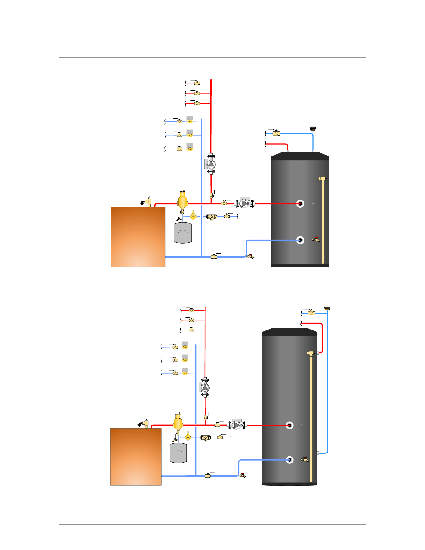
5.0 Piping
The following section describes how to pipe the indirect water heater with the domestic water system.
For reference, see Figure 8.
5.1 Domestic piping
1. Drain the domestic water system:
a. Shut off the cold water supply at the main shutoff valve.
b. Open one or more faucets to relieve the pressure.
c. Open the system drain, leaving the faucets open.
2. After positioning the indirect water heater in the final location, connect the cold water supply to
the DHW inlet connection.
Install the cold water supply using the following suggested components where applicable: a
union, a heat trap, a shut-off valve, a drain valve, an expansion tank, a back flow preventer, and a
vacuum breaker.
3. Connect the domestic hot water piping to the DHW outlet connection using a union, a heat trap,
and a shut-off valve.
4. Pipe the relief valve discharge so that the discharge from the valve will exit within 6 inches above
a suitable drain. The discharge opening must not be blocked or reduced in size under any
circumstances.
5. Fill the indirect water heater with domestic water.
a. Open all faucets to allow air to purge from the indirect water heater and piping.
b. Open the domestic hot water shut-off valve.
c. Slowly open the cold water inlet shut-off valve.
d. Purge all air from the domestic water system.
e. Allow the water to run, so that you clear the indirect water heater of any debris. Run the
water long enough that it runs clear for at least one exchange of the indirect water heater
volume.
f. Close all faucets.
g. Check the system for leaks. Repair as required.
22
Section: Piping
Warning
Do not use automotive-type ethylene or any other type of automotive antifreeze, or
undiluted antifreeze of any kind in the boiler system. This may result in severe boiler
or indirect water heater damage. Installers are responsible for ensuring that glycol
solutions are formulated to inhibit corrosion in hydronic heating systems of mixed
materials. Improper mixtures and chemical additives may cause damage to ferrous and
non-ferrous components as well as damage to non-metallic, wetted components,
normally found in hydronic systems.
Ethylene glycol is toxic and may be prohibited for use by codes applicable to your
installation location. For environmental and toxicity reasons, we recommend only using
non-toxic propylene glycol and non-toxic boiler water additives of any kind.
Note
The piping drawings in Section 10.0 are simple guides to a successful installation.
Many necessary components are not shown, and details such as thermal traps are left
out, so the drawings have greater clarity. We require that our boilers and indirect
water heaters be installed by licensed and experienced trades people who are
familiar with the applicable local and national codes. System design is to be completed
by an experienced hydronic designer or engineer. The application drawings in this
manual are only part of the finished design. You must carefully read and follow these
installation instructions, and just as importantly, the installation instructions for the
boiler model you are using with the indirect water heater.
5.2 Boiler piping
1. Determine where the boiler, the space heating, and the indirect water heater connections should
be made based on the type of heating system, or is to be installed for a new hydronic system
installation. See section Piping Diagrams on page 32 for guidance.
2. The minimum recommended pipe size of the indirect water heater zone is 1” to ensure
adequate flow, 1½" for larger indirect water heaters.
5.3 Zone circulator system
The indirect water heater connection labeled “In from Boiler” should be piped to the boiler supply
piping after the air separator and before the space heating takeoffs.
Mount the indirect water heater circulator as close as is practicable to the indirect water heater, and
make sure the flow arrow points toward the indirect water heater. The use of shut-off valves is
recommended for future service convenience. The indirect water heater connection labeled “Out to
Boiler” should be piped to the boiler return, piping as close to the boiler as possible and after any
flow control or check valves in the space heating return piping. We recommend the use of a union
and a shut-off valve. The use of a check valve is required to prevent back flow through the indirect
water heater during operation of the space heating system.

23
Zone valve system
5.4 Zone valve system
We recommend using a minimum pipe size of 1" and 1" full-port zone valve with a high CV on the
indirect water heater zone to ensure adequate flow.
The indirect water heater connection labeled “In from Boiler” must be piped to the boiler supply
piping after the air separator and grouped with the other zones. The use of a shut-off valve is
recommended for future service convenience.
The indirect water heater connection labeled “Out to Boiler” should be piped to the boiler return
piping and grouped with the other zone returns. We recommend using a union and a shut-off valve.
The use of a check valve is required to prevent back flow through the water heater during operation
of the space heating system.
24
Warning
Scalding from hot water may occur if the DHW setpoint is set too high. The addition of a
scald protection device may be required either at the outlet of the indirect water heater or
at the point of use. Check with your local plumbing authority for local requirements.
6.0 Electrical
1. Install all electrical wiring and grounding according to the National Electrical Code NFPA 70,
latest edition in the US and the Canadian Electrical Code, latest edition in Canada.
2. All indirect water heaters are supplied with a 10KΩ temperature sensor which is compatible
with many boilers that are equipped with an electronic controller. An aquastat can be used with
boilers which are not compatible with the 10KΩ temperature sensor.
3. For indirect water heaters that are supplied with an aquastat. Follow the wiring instructions
supplied with the aquastat and the boiler installation instructions.
6.1 Temperature sensor
The temperature sensor supplied with the indirect water heater is an NTC Thermistor with a
resistance of 10,000 ohms at 25°C and β = 3892. Prior to installation, confirm that the temperature
sensor is compatible with the boiler by confirming the resistance Table 6 matches the temperature
sensor requirements of the boiler.
The temperature sensor allows the boiler to constantly monitor the DHW temperature inside the
indirect water heater and respond when the water temperature falls below the DHW setpoint.
To install the temperature sensor:
1. Insert the temperature sensor bulb fully into the well on the side of the indirect water heater and
secure to prevent it from falling out.
2. Connect the temperature sensor wires to the appropriate terminals of a compatible boiler using
an electrical junction box approved for the application. Reference the boiler installation manual
for wiring details.
3. Set the DHW setpoint on the boiler to the lowest setting which meets the owner’s needs.
Reference the boiler installation manual for programming details.
Danger
Do not connect temperature sensor to “Therm” terminals on a V-10 control board equipped
boiler. It could result in overheating, potentially causing serious personal injury and/or
property damage.
Warning
The temperature sensor supplied with the indirect water heater may not be compatible
with all makes of boiler or controls, and its use may create a hazardous condition. Do
not use the sensor with incompatible boilers. Indirect water heaters are supplied with
a 10kΩ thermistor sensor for inserting into the temperature well, and securing with a
retainer clip or cap. You must solidly affix the thermistor to prevent it from falling out or
from being pulled out. If the sensor is pulled out of the well, a continuous call for hot water
will be generated, resulting in elevated DHW temperatures and risk of scalding.

25
Aquastat
Temperature
Resistance
Temperature
Resistance
°F
°C
Ω
°F
°C
Ω
30
-1
34,558
115
46
4,184
35
2
29,996
120
49
3,760
40
4
26,099
125
52
3,383
45
7
22,763
130
54
3,050
50
10
19,900
135
57
2,754
55
13
17,436
140
60
2,490
60
16
15,311
145
63
2,255
65
18
13,474
150
66
2,045
70
21
11,883
155
68
1,857
75
24
10,501
160
71
1,689
80
27
9,299
165
74
1,538
85
29
8,250
170
77
1,403
90
32
7,334
175
79
1,281
95
35
6,532
180
82
1,172
100
38
5,828
185
85
1,073
105
41
5,210
190
88
983
110
43
4,665
195
91
903
Table 6 Temperature sensor resistance values
6.2 Aquastat
An aquastat regulates the DHW temperature by closing a contact when the DHW temperature
inside the indirect water heater falls below the aquastat setpoint. The aquastat contact opens once
the water temperature reaches the DHW setpoint. Indirect water heaters sold in the USA include a
Honeywell L4080B aquastat.
To install an aquastat:
1. Carefully bend the capillary tube/sensing bulb so that it is at a right angle to the back of the
aquastat.
2. Loosen the mounting screw and carefully insert the sensing bulb into the well on the side of the
indirect water heater until the aquastat mounts to the well head.
3. Tighten the screw to lock in place.
4. Wire the aquastat to the boiler or zone panel. Reference the boiler installation/zone panel
manual for wiring details.
5. Set the DHW setpoint on the aquastat to the lowest setting which meets the owner’s needs.
Warning
Scalding from hot water may occur if the DHW setpoint is set too high. The addition of a
scald protection device may be required either at the outlet of the indirect water heater or
at the point of use. Check with your local plumbing authority for local requirements.
26
7.0 Operation
7.1 Important terms
DHW Setpoint
Indirect water heater storage temperature. Recommend no higher than 140°F to
prevent scalding.
DHW Setpoint
Differential
The variance the control allows in the DHW Setpoint. A differential of 10°F is
recommended.
Boiler DHW
Setpoint
The Boiler setpoint during DHW operation. Should be at least 30°F higher than
the DHW setpoint.
Boiler Setpoint
Differential
The variance allowed in the Boiler DHW setpoint. Recommend setting of 20°F.
Set higher to reduce short cycling around the DHW setpoint.
7.2 Start-up
After the indirect water heater has been plumbed and wired, and the boiler water piping is purged of
air, the indirect water heater is ready to be started. Follow the boiler installation and operating
instructions to place the boiler in operation.
7.3 DHW temperature adjustment
The temperature sensor/aquastat controls the maximum water temperature in the indirect water
heater. If the DHW setpoint is set too high, the resulting hot water can cause painful scalding with
possible serious and permanent injury. The temperature at which this occurs varies with a person’s
age, and the length of time in contact with the hot water. The slower response time of infants, elderly,
or handicapped people increases the hazard for them.
Check the water temperature at a hot water faucet soon after the DHW setpoint has been reached
and the circulator and the boiler have turned off. Adjust as needed.
Lowering the DHW setpoint will not have an immediate effect on the DHW temperature until stored
water is used and the indirect water heater goes through a reheat cycle. Additional temperature
checks should follow the completion of a heating cycle. Further adjustments may be required after
you have used the indirect water heater.
Caution
As a precaution:
After the indirect water heater has reached its setpoint temperature, the installer
should locate a faucet that is unprotected by an over temperature device.
Turn the faucet on full hot and allow it to run long enough to ensure the water and
piping have heated up to the indirect water heater discharge temperature.
Using an accurate thermometer, test the water temperature to ensure it is within
plus or minus 10°F of the DHW setpoint. If there is more deviation, the cause
should be determined, and corrective measures taken.
27
DHW temperature adjustment

28
8.0 Maintenance
The indirect water heater will provide many years of reliable operation. Be aware that components
such as temperature sensors, aquastats, and relief valves may require replacing and servicing.
Depending on the quality of the water supply, sediment and/or scale may coat the coil in the indirect
water heater and reduce the hot water recovery rate. Failure to use the correct procedures or parts
could result in unsafe operation. Owners should arrange follow-up inspections and simple
maintenance procedures according to the maintenance schedule below.
For service or repairs to the indirect water heater, call your heating contractor. To ensure proper
service, the following information is provided to enable the installation, operation, and maintenance
of this indirect water heater. When the installation is completed, keep this manual with the indirect
water heater.
Maintenance Required
Frequency
Check
Boiler and Domestic Water Piping - Check all piping for signs of
leakage at the joints, unions, and shut-off valves. Repair as
required.
Annually
□
Temperature and pressure relief valve - Before testing the
relief valve, make certain the discharge pipe is properly
connected to the valve outlet, and arranged to contain and
safely dispose of hot water discharge.
Annually
□
Sediment - Depending on water conditions, a varying amount
of sediment may collect in the indirect water heater. Levels
requiring service are indicated by a small temperature
difference between the boiler supply and return, and a reduced
recovery rate. Repeated flushing typically clears such material.
As a preventive measure, draw water from the drain valve until it
runs clear and consider installing a water filter.
Annually
(More
frequently in
hard water
areas)
□
Scale - Hard water may cause scale buildup on the outside of
the coil inside the indirect water heater. A water softener can
help prevent this problem. Symptoms are identical to sediment
buildup. If repeated flushing does not resolve the problem,
chemical cleaning may be required.
Annually
□

29
Chemical cleaning of the heating coil
8.1 Chemical cleaning of the heating coil
8.1.1 Flushing the indirect water heater
1. To avoid water damage, shut off the cold water supply to the indirect water heater.
2. When using the temperature sensor, make note of the DHW setpoint in the boiler control, and
turn off the power to the boiler and indirect water heater.
3. Reduce the water pressure in the indirect water heater by opening a hot water faucet.
4. Drain ⅓ of the water so that the indirect water heater is two-thirds full. The water level must
cover the coil and the thermostat well.
5. Remove the relief valve from the indirect water heater.
6. Using a funnel, pour one gallon of commercial ice maker cleaning solution into the indirect
water heater through the relief valve opening. Follow the instructions, cautions, and warnings
supplied with the cleaning solution.
7. Turn on the power to the boiler and indirect water heater.
8. When using the temperature sensor, program the boiler control to its highest DHW setpoint,
and allow the boiler to heat the water until the control is satisfied.
9. When using an aquastat, raise the setpoint to the maximum setpoint and allow the boiler to
heat the water until the aquastat is satisfied.
10. If the DHW setpoint is not reached after 45 minutes of operation, program the DHW setpoint in
the boiler control setting to its lowest temperature or adjust the aquastat to its lowest setting.
11. Allow the heated solution to sit in the indirect water heater for 30 minutes.
12. Drain the indirect water heater completely to remove the cleaning solution.
8.1.2 Refilling the indirect water heater
1. Fill the indirect water heater with fresh, cold water and drain it completely.
2. To flush all the cleaning solution from the indirect water heater, refill and drain at least three (3)
times.
3. Reinstall the relief valve and the drain piping.
4. Open the cold water supply and fill the indirect water heater with water.
5. Purge the air from the indirect water heater and the piping by opening the cold and hot water
faucets in the house.
6. Return the DHW setpoint to the normal setting.
30
9.0 Troubleshooting
Symptom
Diagnosis
Solution
No hot water at faucets
Boiler not operating
Ensure boiler power is on
Ensure the boiler is programed for DHW and
the setpoint is correct
If using a temperature sensor, verify the
DHW temperature on the boiler control
Indirect water heater
circulator not operating
Follow steps for boiler not operating
Ensure the circulator relay is closed and
suppling power to the circulator
Ensure the zone valve is open and the end
switch is closed calling for heat
Check wiring connections at the circulator
Measure voltage at the circulator during a
call for heat, should be 120VAC
If power is at the circulator and connections
are correct, replace circulator
Indirect water heater
zone valve not open
Follow steps for boiler not operating
Check for 24VAC at the zone valve while
there is a call for DHW, if voltage is correct
and wire connections are good, replace the
zone valve
Incorrect temperature
sensor reading
Ensure the temperature sensor bulb is at the
bottom of the well
Ensure the temperature sensor is wired to
the correct boiler terminals
Disconnect the temperature sensor from the
boiler terminals and measure the resistance.
Compare the measured resistance with the
value shown in Table 6.
Repair any wiring issues causing an open or
short circuit.
Replace temperature sensor if resistance
reading is incorrect
Water at faucets too
cold
DHW setpoint set to
low
Increase the DHW setpoint in the boiler
control if using a temperature sensor
Increase the DHW setpoint of the aquastat
when using an aquastat
Boiler setpoint set to
low
Ensure the boiler setpoint for a DHW
demand is at least 10°F (6°C) higher than
the DHW setpoint

31
Troubleshooting
Water at faucets too
hot
DHW setpoint set to
high
Decrease the DHW setpoint in the boiler
control if using a temperature sensor
Decrease the DHW setpoint of the aquastat
when using an aquastat
Incorrect temperature
sensor reading
Ensure the temperature sensor bulb is at the
bottom of the well
Ensure the temperature sensor is wired to
the correct boiler terminals
Confirm the temperature sensor is
compatible with the boiler
Temperature &
pressure relief valve
discharges periodically
Thermal expansion
Check the potable expansion tank and
service/replace as necessary
If temperature and pressure during
operation are below the maximums, replace
the relief valve
Do not plug the relief valve.
32
10.0 Piping Diagrams
Domestic
Water
Cold
Hot
Generic Boiler
Figure 4 Top DHW connection model - generic boiler piping
Domestic
Water
Cold
Hot
Generic Boiler
Figure 5 Side DHW connection model – generic boiler piping
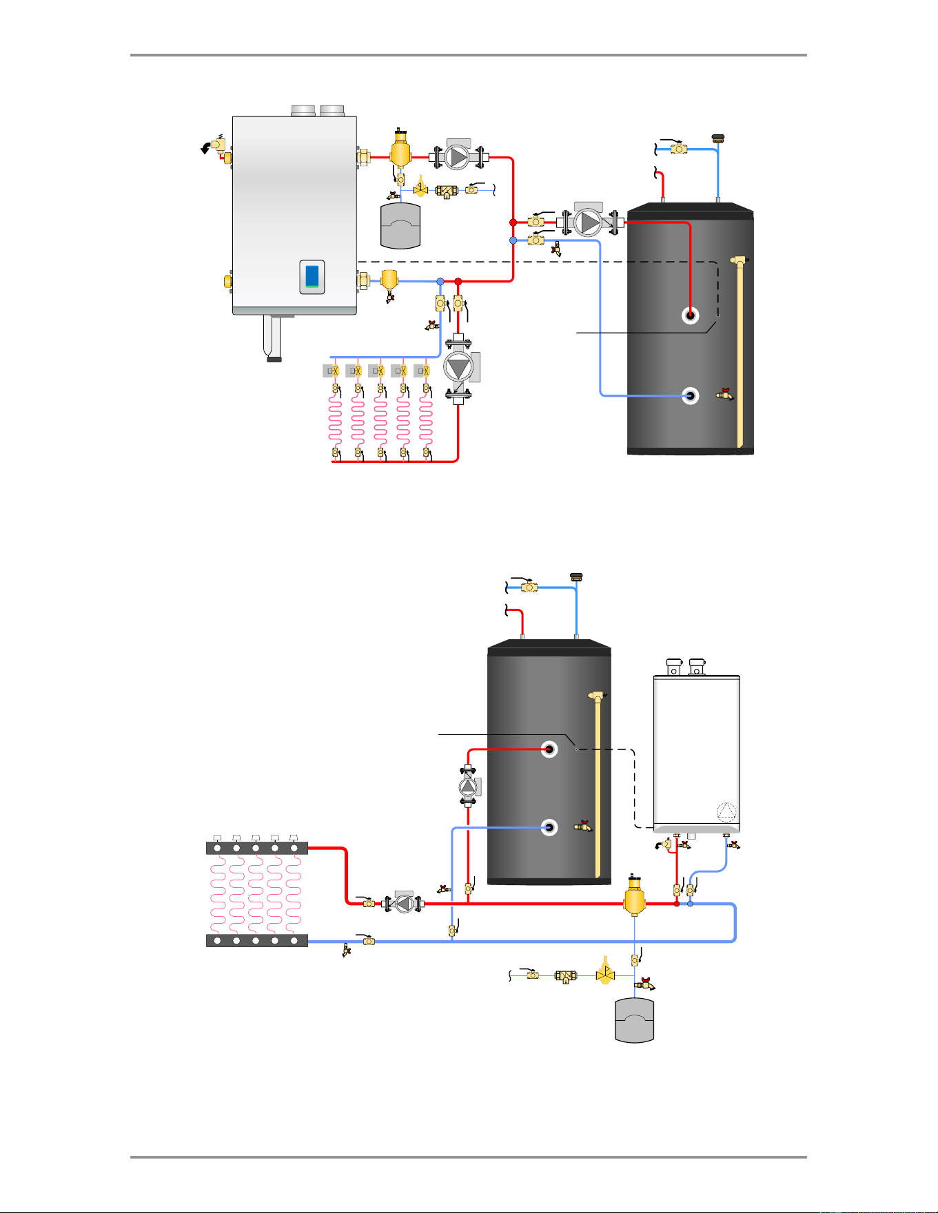
33
Piping Diagrams
Domestic
Water
Cold
Hot
Domestic
Hot Water
Sensor
Water
Tube
Boiler
IBC Boiler
SL 20-115-G2
V-10
Control
Boiler
Domestic
Water
Cold
Hot
Domestic
Hot Water
Sensor
Figure 6 Top DHW connection model - V-10 control boiler
Figure 7 Top DHW connection model - water tube boiler
34
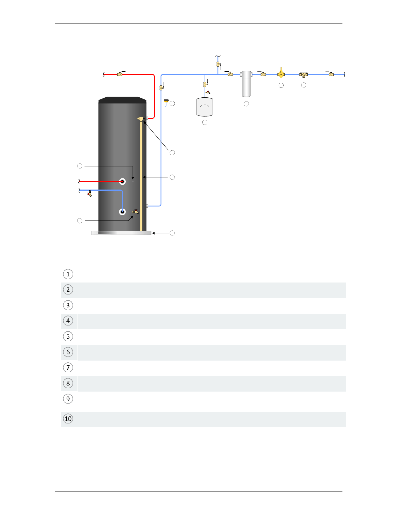
Section: Piping Diagrams
Vacuum breaker
Relief valve discharge pipe
Potable expansion tank - required where backflow check valves are installed.
Pressure reducing valve - required where mains pressure exceeds maximum indirect water
heater pressure rating
Backflow preventer - wherever required by local code
Whole house water filter - required where contaminants are present in the water supply
Drain pan
Temperature & pressure relief valve
Drain valve
Domestic
Hot Water
Fresh Water
from Mains
Cold Water
to House
Whole House
Shutoff Valve
DHW Tank
Shut Off Valve
DHW Tank
Shut Off Valve
2
3
1
5
6
7
4
8
9
10
To Heat
Source
Figure 8 Suggested domestic water piping
Temperature sensor well
Even if components shown in Figure 8 are not required by code in your jurisdiction, we strongly
recommend the external components. At the very least, we require installation of a vacuum breaker
in the position shown, with no shut-off valves between the device and the indirect water heater.
Important Note: All external components shown are field supplied.

35
11.0 Replacement Parts
Part Number
Description
P-9073
10KΩ temperature sensor
P-9017
Aquastat

IBC Technologies Inc.
8015 North Fraser Way
Burnaby, BC Canada V5J 5M8
T 604-877-0277
F 604-877-0295
Toll Free: 1-844-HEAT-IBC/ 1-844-432-8422
IBC Technologies USA Inc.
121 Walter A Gaines Way
Lawnside, NJ 08045 USA
T 856-877-0544
F 856-735-5584
Rheem Sales Co.
Montgomery, AL.
T 833-212-9276
Information in this document is subject to change without notice. We assume no responsibility for
changes made to the manual due to clerical errors, to regulation changes, or to product development.
May 28, 2025 | 900-838
© 2025


