EN
USER AND SAFETY GUIDE
DIN MOUNTABLE 2-CIRCUIT WI-FI SMART
RELAY WITH POWER MEASUREMENT
FUNCTIONALITY
SHELLY® PRO 2PM
Read before use
This document contains important technical and safety informa-
tion about the device, its safety use and installation.
⚠CAUTION! Before beginning the installation, please read this
guide and any other documents accompanying the device carefully
and completely. Failure to follow the installation procedures could
lead to malfunction, danger to your health and life, violation of the
law or refusal of legal and/or commercial guarantee (if any). All-
terco Robotics EOOD is not responsible for any loss or damage in
case of incorrect installation or improper operation of this device
due to failure of following the user and safety instructions in this
guide.
Product Introduction
Shelly® is a line of innovative microprocessor-managed devices,
which allow remote control of electric circuits through a mobile
phone, tablet, PC, or home automation system. Shelly® devices
can work standalone in a local Wi-Fi network or they can also be
operated through cloud home automation services. Shelly Cloud
is a service that can be accessed using either Android or iOS
mobile application, or with any internet browser at https://home.
shelly.cloud/. Shelly® devices can be accessed, controlled and
monitored remotely from any place where the User has internet
connectivity, as long as the devices are connected to a Wi-Fi router
and the Internet. Shelly® devices have embedded Web Interface
accessible at http://192.168.33.1 when connected directly to the
device access point, or at the device IP address on the local Wi-Fi
network. The embedded Web Interface can be used to monitor
and control the device, as well as adjust its settings.
Shelly® devices can communicate directly with other Wi-Fi devic-
es through HTTP protocol. An API is provided by Allterco Robotics
EOOD. For more information, please visit:
https://shelly-api-docs.shelly.cloud/#shelly-family-overview.
Shelly® devices are delivered with factory-installed rmware. If
rmware updates are necessary to keep the devices in conformi
-
ty, including security updates, Allterco Robotics EOOD will provide
the updates free of charge through the device embedded Web In-
terface or Shelly Mobile Application, where the information about
the current rmware version is available. The choice to install or
not the device rmware updates is user’s sole responsibility. All-
terco Robotics EOOD shall not be liable for any lack of conformity
of the device caused by failure of the user to install the provided
updates in a timely manner.
Control your home with your voice
Shelly® devices are compatible with Amazon Alexa and Google
Home supported functionalities. Please see our step-by-step
guide on: https://shelly.cloud/support/compatibility/.
Shelly® Pro Series
Shelly® Pro series is a line of devices suitable for homes, oces,
retail stores, manufacturing facilities, and other buildings. Shelly®
Pro devices are DIN mountable inside the breaker box, and highly
suitable for new building construction. All Shelly® Pro devices can
be controlled and monitored through Wi-Fi and LAN connections.
Bluetooth connection can be used for the inclusion process.
Shelly® Pro 2PM (the Device) is a DIN rail mountable 2-circuit
smart relay with power measurement and cover control function
-
alities. Enhanced with the second generation rmware exibility
and LAN connectivity, it provides the professional integrators with
much more options for end customer solutions.
Schematic - to the left
Installation Instructions
⚠CAUTION! Danger of electrocution. Mounting/installation of the
Device to the power grid has to be performed with caution, by a
qualied electrician.
⚠CAUTION! Danger of electrocution. Every change in the connec
-
tions has to be done after ensuring there is no voltage present at
the Device terminals.
⚠CAUTION! Use the Device only with a power grid and appliances
which comply with all applicable regulations. A short circuit in the
power grid or any appliance connected to the Device may damage
the Device.
⚠CAUTION! Do not connect the Device to appliances exceeding
the given max load!
⚠CAUTION! Connect the Device only in the way shown in these
instructions. Any other method could cause damage and/or injury.
⚠CAUTION! Do not install the device at a place that is possible
to get wet.
⚠CAUTION! Allow at least 10 mm of space around each Pro de-
vice if you expect currents higher than 5 A per channel.
⚠RECOMMENDATION Connect the Device using solid single-core
cables with increased insulation heat resistance not less than PVC
T105°C.
Before starting installing/mounting the Device, wire check that the
breakers are turned off and there is no voltage on their terminals.
This can be done with a phase meter or multimeter. When you
are sure that there is no voltage, you can proceed to connecting
the cables.
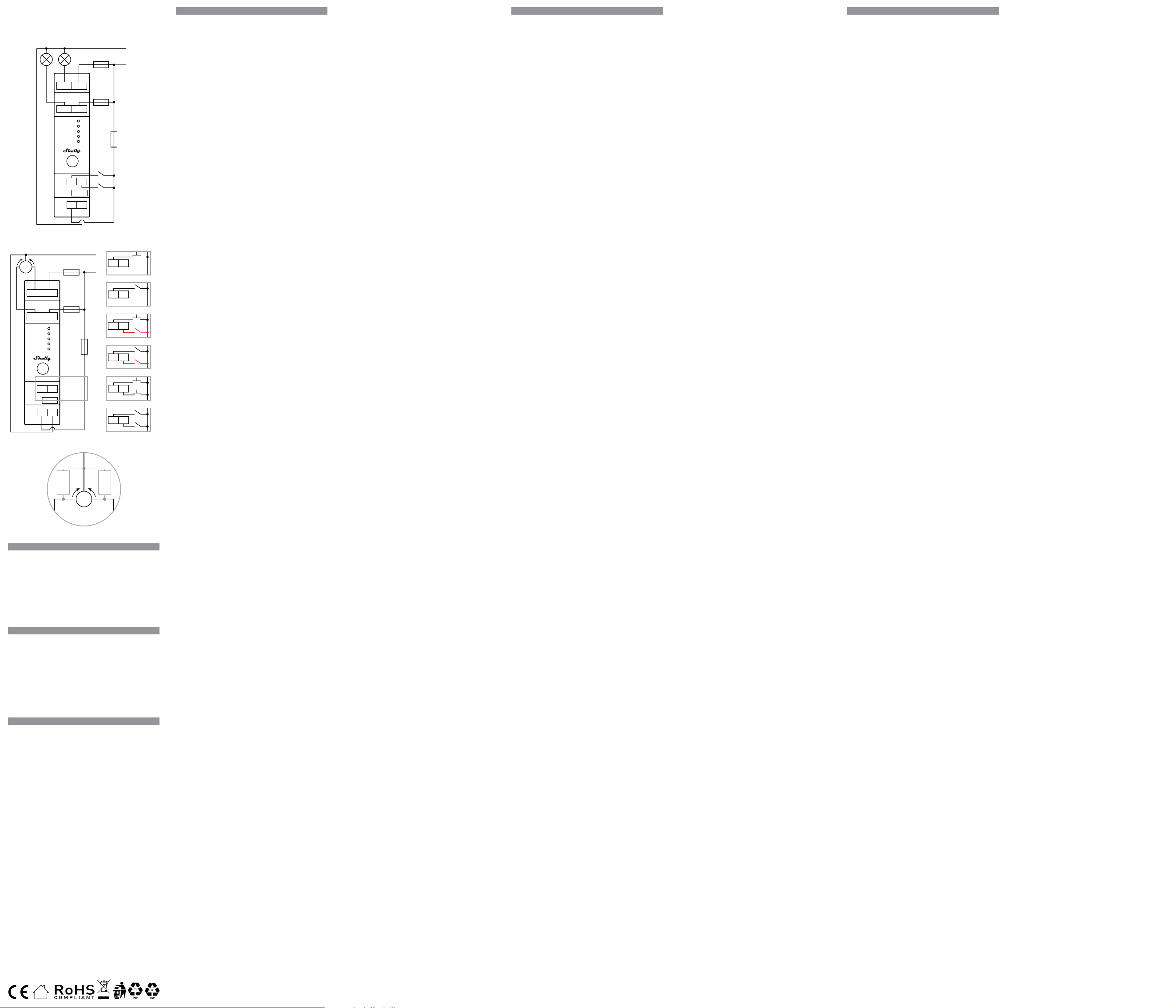
If you want to use Shelly® Pro 2PM as a 2-circuit relay, connect
the N terminal to the Neutral cable and the L terminal to the Device
power supply circuit breaker as shown on Fig. 1. Connect the rst
load circuit to the O1 terminal and the Neutral cable. Connect the
I1 terminal to the rst load circuit breaker. Connect the second
load circuit to the O2 terminal and the Neutral cable. Connect the
I2 terminal to the second load circuit breaker.
Connect the two switches/buttons to the S1 and S2 terminals and
the Device power supply circuit breaker.
⚠CAUTION! Use one and the same phase for both load circuits
and the Device power supply circuit.
⚠RECOMMENDATION: For inductive appliances that cause volt-
age spikes during switching on/off, such as electrical motors, fans,
vacuum cleaners and similar ones, RC snubber (0.1µF / 100 Ω / 1/2
W / 600 VAC) should be connected parallel to the appliance. The RC
snubber can be purchased at
https://shop.shelly.cloud/rc-snubber-wi-smart-home-automation
.
As a cover controller Shelly® Pro2PM can work in 3 modes: de-
tached, single input or dual input.
In detached mode, the Device can be controlled through its Web
Interface and the App only. Even if buttons or switches are con
-
nected to the Device, they will not be allowed to control the motor
rotation in detached mode, but they can be used for URL actions.
If you want to use the Device in detached mode connect the de
-
vice as shown on Fig. 2 a). Connect the N terminal to the Neu-
tral cable and the L terminal to the Device power supply circuit
breaker. Connect the common motor terminal/cable to the Neutral
cable. Connect motor direction terminals/cables to the O1 and O2
terminals*. Connect the I1 terminal to one of circuit breakers and
the I2 terminal to the other circuit breaker.
If you want to use the Device in single input mode connect the
device as shown on Fig. 2 b) for a button input or Fig. 2 c) for a
switch input. Connect the N terminal to the Neutral cable and the
L terminal to the Device power supply circuit breaker. Connect the
common motor terminal/cable to the Neutral cable. Connect mo-
tor direction terminals/cables to the O1 and O2 terminals*. Con-
nect the I1 terminal to one of circuit breakers and the I2 terminal
to the other circuit breaker.
Connect the button or the switch to the S1 terminal and the Device
power supply circuit breaker.
If the input is congured as a button in the Device settings, each
button press cycles open, stop, close, stop, etc.
If the input is congured as a switch, each switch toggle cycles
open, stop, close, stop, etc.
In single input mode Shelly® Pro 2PM provides safety switch
functionality. To utilize it, connect the device as shown on Fig. 2 d)
for a button input or Fig. 2 e) for a switch input. Connect the N ter-
minal to the Neutral cable and the L terminal to the Device power
supply circuit breaker. Connect the common motor terminal/cable
to the Neutral cable. Connect motor direction terminals/cables to
the O1 and O2 terminals*. Connect the I1 terminal to one of circuit
breakers and the I2 terminal to the other circuit breaker.
Connect the controlling button or switch to the S1 terminal and
the Device power supply circuit breaker. Connect the safety switch
to the S2 terminal and the Device power supply circuit breaker.
The safety switch can be congured to:
DE
BENUTZER- UND SICHERHEITSHANDBUCH
DIN-MONTIERBARES 2-KREIS-WI-FI-SMART-
RELAIS MIT LEISTUNGSMESSUNGSFUNKTION
SHELLY® PRO 2PM
Bitte vor Gebrauch durchlesen
Dieses Dokument enthält wichtige technische und sicherheitstech-
nische Informationen über das Gerät und seine sichere Verwendung
und Installation.
⚠ACHTUNG! Bevor Sie mit der Installation beginnen, lesen Sie bitte
die Begleitdokumentation sorgfältig und vollständig durch. Die Nichtbe-
achtung der empfohlenen Verfahren kann zu Fehlfunktionen, Lebens-
gefahr oder Gesetzesverstößen führen. Allterco Robotics EOOD haftet
nicht für Verluste oder Schäden im Falle einer falschen Installation oder
Bedienung dieses Geräts.
Produktvorstellung
Shelly® ist eine Produktserie innovativer, mikroprozessorgesteuerter
Geräte, welche die Fernsteuerung von Elektrogeräten über ein Mobil-
telefon, ein Tablet, einen PC oder ein Hausautomatisierungssystem
ermöglichen. Shelly® Geräte können eigenständig in einem lokalen
WLAN-Netzwerk arbeiten oder sie können auch über Cloud-Dienste
für die Hausautomatisierung betrieben werden. Shelly Cloud ist ein
solcher Dienst, auf den entweder über eine Android- oder iOS-Ap-
plikation oder über einen beliebigen Internetbrowser unter https://
home.shelly.cloud/ zugegriffen werden kann. Shelly® Geräte können
von jedem Ort aus, an dem der Benutzer eine Internetverbindung hat,
angesprochen, gesteuert und überwacht werden, solange die Geräte
mit einem WLAN-Router und dem Internet verbunden sind. Shelly®
Geräte verfügen über eine integrierte Web-Schnittstelle, die unter
http://192.168.33.1 im WLAN-Netzwerk zugänglich ist, das vom Ge-
rät im Access Point-Modus erstellt wird, oder unter der IP-Adresse des
Gerätes im WLAN-Netzwerk, mit dem es verbunden ist. Díe integrierte
Web-Schnittstelle kann zur Überwachung und Steuerung des Gerätes
sowie zur Anpassung dessen Einstellungen verwendet werden.
Shelly® Geräte können direkt mit anderen WLAN-Geräten über das
HTTP-Protokoll kommunizieren. Eine API wird von Allterco Robotics
EOOD bereitgestellt. Für weitere Informationen besuchen Sie bitte:
https://shelly-api-docs.shelly.cloud/#shelly-family-overview.
Shelly® Geräte werden mit werkseitig installierter Firmware ausgelie-
fert. Um die Geräte konform zu halten, stellt Allterco Robotics EOOD
die notwendigen Firmware-Updates, einschließlich der Sicherheits-
updates, kostenlos über die im Gerät eingebettete Web-Schnittstelle
sowie über die Shelly-App zur Verfügung. Die Entscheidung, die Firm-
ware-Updates des Geräts zu installieren oder nicht, obliegt der allei-
nigen Verantwortung des Benutzers. Allterco Robotics EOOD haftet
nicht für Konformitätsmängel des Geräts, die darauf zurückzuführen
sind, dass der Benutzer die bereitgestellten Updates nicht rechtzeitig
installiert hat.
Steuern Sie Ihr Zuhause mit Ihrer Stimme
Shelly® Geräte sind mit den von Amazon Alexa und Google Home
unterstützten Funktionalitäten kompatibel. Bitte sehen Sie sich unse
-
re Schritt-für-Schritt-Anleitung an:
https://shelly.cloud/support/compatibility/.
Shelly® Pro-Serie
Die Shelly® Pro-Serie ist eine Produktserie, die für Wohnungen, Büros,
Einzelhandelsgeschäfte, Produktionsstätten und andere Gebäude
geeignet ist. Sie sind auf der DIN-Schiene im Stromkasten montier-
bar und sehr gut für den Neubau geeignet. Alle Shelly® Pro-Geräte
können sowohl über eine WLAN- als auch über eine LAN-Verbindung
gesteuert und überwacht werden. Bluetooth kann zusätzlich für die
Einbindung genutzt werden.
Shelly® Pro 2PM (das Gerät) ist ein auf DIN-Schienen montierbares
smartes 2-Kreis-Smart-Relais mit Leistungsmess- und Abdeckungs
-
steuerungsfunktionen. Verbessert mit der zweiten Generation der
Firmware-Flexibilität und LAN-Konnektivität, bietet es den professio-
nellen Installateuren viel mehr Optionen für ihre Endkundenlösungen.
Schematische Darstellung - Nach links
Installationsanleitung
⚠VORSICHT! Gefahr eines Stromschlages. Die Montage/Installation
des Geräts an das Stromnetz muss von einem qualizierten Elektriker
mit Vorsicht durchgeführt werden.
⚠VORSICHT! Es besteht Stromschlaggefahr. Bei jeder Änderung der
Anschlüsse muss sichergestellt werden, dass an den Klemmen des
Geräts keine Spannung anliegt.
⚠VORSICHT! Verwenden Sie das Gerät nur mit einem Stromnetz und
Geräten, die allen geltenden Vorschriften entsprechen. Ein Kurzschluss
im Stromnetz oder in einem an das Gerät angeschlossenen Gerätes
kann dieses beschädigen.
⚠VORSICHT! Schließen Sie das Gerät nicht an Geräte an, die die an
-
gegebene Höchstlast überschreiten!
⚠VORSICHT! Schließen Sie das Gerät nur auf die in dieser Anleitung
beschriebene Weise an. Jede andere Methode kann zu Schäden und/
oder Verletzungen führen.
⚠VORSICHT! Installieren Sie das Gerät nicht an einem Ort, an dem
es nass werden kann.
⚠ACHTUNG! Lassen Sie um jedes Pro-Gerät herum mindestens 10
mm Platz, wenn Sie Stromstärken von mehr als 5 A pro Kanal erwarten.
⚠EMPFEHLUNG: Schließen Sie das Gerät mit massiven einadrigen
Kabeln mit erhöhter Isolationswärmebeständigkeit von mindestens
PVC T105°C an.
Bevor Sie mit der Installation/Montage des Geräts beginnen, prüfen
Sie, ob die Leitungsschutzschalter (Sicherungen) ausgeschaltet sind
und keine Spannung an den Klemmen anliegt. Dies kann mit einem
Phasenmesser oder Multimeter erfolgen. Wenn Sie sicher sind, dass
keine Spannung anliegt, können Sie mit dem Anschluss der Kabel
fortfahren.
Wenn Sie Shelly® Pro 2PM als 2-Kreis-Relais verwenden möchten,
schließen Sie die N-Klemme an das Neutralleiterkabel und die L-Klem
-
me an den Gerätestromversorgungs-Leistungsschalter an, wie in Abb.
1 dargestellt.
Schließen Sie den ersten Lastkreis an die Klemme O1 und das Null
-
leiterkabel an. Schließen Sie die Klemme I1 an den ersten Laststrom-
kreisunterbrecher an. Schließen Sie den zweiten Lastkreis an die
Klemme O2 und das Nullleiterkabel an. Verbinden Sie die Klemme I2
mit dem zweiten Lasttrennschalter.
Schließen Sie die beiden Schalter/Taster an die Klemmen S1 und S2
und den Geräteschutzschalter an.
⚠ACHTUNG! Verwenden Sie für beide Laststromkreise und den
Stromversorgungsstromkreis des Geräts ein und dieselbe Phase.
⚠EMPFEHLUNG: Bei induktiven Geräten, die beim Ein- und Ausschal-
ten Spannungsspitzen verursachen, wie z. B. Elektromotoren, Ventila-
toren, Staubsauger und ähnliche, sollte ein RC-Dämpfer (0,1µF / 100
Ω / 1/2 W / 600 VAC) parallel zum Gerät angeschlossen werden. Der
RC-Snubber kann unter
https://shop.shelly.cloud/rc-snubber-wi-smart-home-automation
er-
worben werden.
Als Cover Controller kann Shelly® Pro2PM in 3 Modi arbeiten: freiste
-
hend, mit einem Eingang oder mit zwei Eingängen.
Im getrennten Modus kann das Gerät nur über seine WebUI und die
App gesteuert werden. Selbst wenn Taster oder Schalter an das Gerät
angeschlossen sind, können diese die Motordrehung im getrennten
Modus nicht steuern, aber sie können für URL-Aktionen verwendet
werden.
Wenn Sie das Device im getrennten Modus verwenden möchten,
schließen Sie das Device wie in Abb. 2 a) gezeigt an. Verbinden Sie
die Klemme N mit dem Neutralkabel und die Klemme L mit dem
Schutzschalter der Stromversorgung des Geräts. Verbinden Sie die ge-
meinsame Motorklemme bzw. das gemeinsame Motorkabel mit dem
Nullleiter. Die Klemmen/Kabel für die Motorrichtung an die Klemmen
O1 und O2* anschließen. Schließen Sie die Klemme I1 an einen der
Schutzschalter und die Klemme I2 an den anderen Schutzschalter an.
Wenn Sie das Gerät im Einzeleingangsmodus verwenden wollen,
schließen Sie es wie in Abb. 2 b) für einen Tastereingang oder Abb. 2
c) für einen Schaltereingang an. Verbinden Sie die Klemme N mit dem
Neutralkabel und die Klemme L mit dem Leistungsschalter für die
Stromversorgung des Geräts. Die gemeinsame Motorklemme bzw.
das gemeinsame Motorkabel an das Nullleiterkabel anschließen. Die
Klemmen/Kabel für die Motorrichtung an die Klemmen O1 und O2* an
-
schließen. Schließen Sie die Klemme I1 an einen der Schutzschalter
und die Klemme I2 an den anderen Schutzschalter an.
Schließen Sie den Taster oder den Schalter an die Klemme S1 und den
Schutzschalter der Geräteversorgung an.
Wenn der Eingang in den Geräteeinstellungen als Taster konguriert
ist, werden bei jedem Tastendruck die Zyklen Öffnen, Stopp, Schlie-
ßen, Stopp usw. ausgeführt.
Wenn der Eingang als Schalter konguriert ist, wird bei jedem Um
-
schalten des Schalters der Zyklus Öffnen, Stopp, Schließen, Stopp
usw. ausgeführt.
Im Einzeleingabemodus bietet Shelly® Pro 2PM eine Sicherheits-
IT
GUIDA ALL’USO E ALLA SICUREZZA
SMART RELAY WI-FI A 2 CIRCUITI MONTABILE
SU GUIDA DIN CON FUNZIONALITÀ DI
MISURAZIONE DELLA POTENZA
SHELLY® PRO 2PM
Leggere prima dell’uso
Questo documento contiene importanti informazioni tecniche e
di sicurezza sul dispositivo e sul suo uso e installazione in si
-
curezza.
⚠ATTENZIONE! Prima di iniziare l’installazione leggere attenta-
mente e completamente la documentazione allegata. La mancata
osservanza delle procedure consigliate potrebbe portare a malfun-
zionamenti, pericolo per la vita o violazione della legge. Allterco
Robotics EOOD non è responsabile per eventuali perdite o danni in
caso di installazione o funzionamento errati di questo dispositivo.
Introduzione al prodotto
Shelly® è una linea di dispositivi innovativi gestiti da micropro-
cessori che permettono il controllo remoto degli elettrodomestici
attraverso un telefono cellulare, un tablet, un PC o un sistema do-
motico. I dispositivi Shelly® sono in grado di funzionare autono-
mamente in una rete Wi-Fi locale o possono anche essere gestiti
attraverso servizi di automazione domestica cloud. Shelly Cloud è
un servizio di questo tipo a cui si può accedere utilizzando un’ap-
plicazione mobile Android o iOS o con qualsiasi browser internet
su https://home.shelly.cloud/. I dispositivi Shelly® sono accessi-
bili, controllati e monitorati a distanza da qualsiasi luogo in cui
l’utente abbia una connettività Internet, purché i dispositivi siano
collegati a un router Wi-Fi e a Internet. I dispositivi Shelly® hanno
un’interfaccia web incorporata accessibile a http://192.168.33.1
nella rete Wi Fi, creata dal dispositivo in modalità Access Point, o
all’indirizzo URL del dispositivo nella rete Wi-Fi a cui è connesso.
L’interfaccia web incorporata può essere utilizzata per monitorare
e controllare il dispositivo, così come per regolare le sue impo-
stazioni.
I dispositivi Shelly® sono in grado di comunicare direttamente
con altri dispositivi Wi-Fi attraverso il protocollo HTTP. Un’API è
fornita da Allterco Robotics EOOD. Per maggiori informazioni,
visitare:
https://shelly-api-docs.shelly.cloud/#shelly-family-overview.
I dispositivi Shelly® vengono consegnati con un rmware instal-
lato in fabbrica. Se sono necessari aggiornamenti del rmware
per mantenere i dispositivi in conformità, compresi gli aggiorna-
menti di sicurezza, Allterco Robotics EOOD fornirà gli aggiorna-
menti gratuitamente attraverso l’interfaccia web incorporata del
dispositivo o l’applicazione mobile Shelly, dove sono disponibili le
informazioni sulla versione corrente del rmware. La scelta di in-
stallare o meno gli aggiornamenti del rmware del dispositivo è di
esclusiva responsabilità dell’utente. Allterco Robotics EOOD non è
responsabile per qualsiasi mancanza di conformità del dispositi
-
vo causata dalla mancata installazione degli aggiornamenti forniti
dall’utente in modo tempestivo.
Controlla la tua casa con la tua voce
I dispositivi Shelly® sono compatibili con le funzionalità suppor-
tate da Amazon Alexa e Google Home. Consulta la nostra guida
passo dopo passo su:
https://shelly.cloud/support/compatibility/.
Shelly® Pro Series
La serie Shelly® Pro è una linea di dispositivi adatti per abitazioni,
uci, negozi al dettaglio, impianti di produzione e altri edici. I
dispositivi Shelly® Pro sono montabili DIN all’interno della scatola
dell’interruttore e sono particolarmente adatti per la costruzione
di nuovi edici. La connettività per tutti i dispositivi Shelly® Pro
può avvenire tramite connessione Internet Wi-Fi o LAN e il Blueto-
oth può essere utilizzato per il processo di inclusione.
Shelly® Pro 2PM (il Dispositivo) è un relè intelligente a 2 circui-
ti montabile su guida DIN con funzionalità di misurazione della
potenza e controllo della copertura. Grazie alla essibilità del
rmware di seconda generazione e alla connettività LAN, offre
agli integratori professionali molte più opzioni per le soluzioni dei
clienti nali.
Schema - A sinistra
Istruzioni per l’installazione
⚠ATTENZIONE! Pericolo di folgorazione. Il montaggio/installa-
zione del dispositivo alla rete elettrica deve essere eseguito con
cautela da un elettricista qualicato.
⚠ATTENZIONE! Pericolo di folgorazione. Ogni modica dei colle-
gamenti deve essere effettuata dopo essersi assicurati che non ci
sia tensione ai morsetti dell’apparecchio.
⚠ATTENZIONE! Utilizzare l’apparecchio solo con una rete elet
-
trica e con apparecchi conformi a tutte le norme vigenti. Un cor-
tocircuito nella rete elettrica o in qualsiasi apparecchio collegato
all’apparecchio può danneggiare l’apparecchio.
⚠ATTENZIONE! Non collegare l’apparecchio ad apparecchi che
superano il carico massimo indicato!
⚠ATTENZIONE! Collegare l’apparecchio solo nel modo indicato
in queste istruzioni. Qualsiasi altro metodo potrebbe causare danni
e/o lesioni.
⚠ATTENZIONE! Non installare il dispositivo in un luogo che pos
-
sa bagnarsi.
⚠ATTENZIONE! Lascia almeno 10 mm di spazio attorno a cia-
scun dispositivo Pro se prevedi correnti superiori a 5 A per canale.
⚠RACCOMANDAZIONE Collegare il dispositivo utilizzando cavi
unipolari solidi con una maggiore resistenza termica dell’isolamen
-
to non inferiore a PVC T105°C.
Prima di iniziare l’installazione/montaggio del dispositivo, control
-
lare che gli interruttori siano spenti e che non ci sia tensione sui
loro terminali. Questo può essere fatto con un misuratore di fase
o un multimetro. Quando siete sicuri che non c’è tensione, potete
procedere al collegamento dei cavi.
“Se si desidera utilizzare lo Shelly® Pro 2PM come relè a 2 circuiti,
collegare il morsetto N al cavo di neutro e il morsetto L all’interrut-
tore di alimentazione del dispositivo, come illustrato nella Fig. 1.
Collegare il primo circuito di carico al terminale O1 e al cavo di
neutro. Collegare il terminale I1 al primo interruttore di carico.
Collegare il secondo circuito di carico al terminale O2 e al cavo di
neutro. Collegare il terminale I2 al secondo interruttore di carico.
Collegare i due interruttori/pulsanti ai morsetti S1 e S2 e all’inter
-
ruttore di alimentazione del dispositivo.
⚠ATTENZIONE! Utilizzare una stessa fase per entrambi i circuiti
di carico e per il circuito di alimentazione del dispositivo.
⚠RACCOMANDAZIONE: per gli apparecchi induttivi che causano
picchi di tensione durante l’accensione e lo spegnimento, come
motori elettrici, ventilatori, aspirapolvere e simili, è necessario col-
legare in parallelo all’apparecchio uno snubber RC (0,1µF / 100 Ω
/ 1/2 W / 600 VAC). Lo snubber RC può essere acquistato sul sito
https://shop.shelly.cloud/rc-snubber-wi-smart-home-automation
.
Come Cover Controller, Shelly® Pro2PM può funzionare in 3 mo-
dalità: staccato, a ingresso singolo o doppio.
In modalità distaccata, il dispositivo può essere controllato solo
attraverso la l’interfaccia Web e l’App. Anche se al Dispositivo
sono collegati pulsanti o interruttori, in modalità distaccata non
potranno controllare la rotazione del motore, ma potranno essere
utilizzati per azioni URL.
Se si desidera utilizzare il dispositivo in modalità distaccata,
collegarlo come illustrato nella Fig. 2 a). Collegare il terminale N
al cavo di neutro e il terminale L all’interruttore di alimentazione
del dispositivo. Collegare il terminale/cavo comune del motore al
cavo di neutro. Collegare i terminali/cavi della direzione del mo
-
tore ai terminali O1 e O2*. Collegare il terminale I1 a uno degli
interruttori e il terminale I2 all’altro interruttore.
Se si desidera utilizzare il dispositivo in modalità ingresso sin
-
golo, collegarlo come mostrato nella Fig. 2 b) per un ingresso a
pulsante o nella Fig. 2 c) per un ingresso a interruttore. Collegare
il terminale N al cavo di neutro e il terminale L all’interruttore di
alimentazione del dispositivo. Collegare il terminale/cavo comune
del motore al cavo di neutro. Collegare i terminali/cavi di direzione
del motore ai terminali O1 e O2*. Collegare il terminale I1 a uno
degli interruttori e il terminale I2 all’altro interruttore.
Collegare il pulsante o l’interruttore al terminale S1 e all’interrutto
-
re di alimentazione del dispositivo.
Se l’ingresso è congurato come pulsante nelle impostazioni del
dispositivo, ad ogni pressione del pulsante vengono eseguiti cicli
di apertura, arresto, chiusura, arresto eccetera.
Se l’ingresso è congurato come interruttore, ad ogni commuta-
zione dell’interruttore vengono eseguiti cicli di apertura, arresto,
chiusura, arresto eccetera.
In modalità ingresso singolo, Shelly® Pro 2PM offre la funziona-
- Stop the movement until the safety switch is disengaged or until
a command is sent** and, if allowed in the Device settings, the
movement is resumed in the opposite direction until the end po-
sition is reached.
- Stop and immediately reverse the movement until the end po-
sition is reached. This option requires reverse movement to be
allowed in the Device settings.
The safety switch can also be congured to stop the movement in
only one of the directions or in both.
If you want to use the Device in dual input mode, connect the de-
vice as shown on Fig. 2 f) for a button inputs or Fig. 2 g) for a
switch inputs. Connect the N terminal to the Neutral cable and the
L terminal to the Device power supply circuit breaker. Connect the
common motor terminal/cable to the Neutral cable. Connect mo-
tor direction terminals/cables to the O1 and O2 terminals*. Con-
nect the I1 terminal to one of circuit breakers and the I2 terminal
to the other circuit breaker.
Connect the rst button or switch to the S1 terminal and the
Device power supply circuit breaker. Connect the second button
or switch to the S2 terminal and the Device power supply circuit
breaker.
In case the inputs are congured as buttons:
- Pressing a button when the cover is static, moves the cover in the
corresponding direction until the endpoint is reached.
- Pressing the button for the same direction while the cover is
moving, stops the cover.
- Pressing the button for the opposite direction, while the cover
is moving, reverses the cover movement until the endpoint is
reached.
In case the inputs are congured as switches:
- Turning a switch on moves the cover in the corresponding direc-
tion until an endpoint is reached.
- Turning the switch off stops the cover movement.
If both switches are turned on, Shelly® Pro 2PM will respect the
last engaged switch. Turning off the last engaged switch stops
the cover movement, even if the other switch is still on. To move
the cover in the opposite direction, the other switch has to be
turned off and on again.
Shelly® Pro 2PM can detect obstacles. If an obstacle is present,
the cover movement will be stopped and, if congured so in the
Device settings, reversed until the endpoint is reached. Obstacle
detection can be enabled or disabled for only one of the directions
or for both.
⚠RECOMMENDATION: To avoid voltage spikes during switching
on/off the cover bi-directional motor, two RC snubbers (0.1µF /
100Ω / 1/2W / 600V AC) should be connected between the com-
mon and the two direction terminals/cables of the cover motor as
shown on Fig. 3.
The RC snubbers can be purchased at
https://shop.shelly.cloud/rc-snubber-wi-smart-home-automation
Initial Inclusion
If you choose to use the Device with the Shelly Cloud mobile ap-
plication and Shelly Cloud service, instructions on how to connect
the Device to the Cloud and control it through the Shelly App can
be found in the “App Guide”.
The Shelly Mobile Application and Shelly Cloud service are not
conditions for the Device to function properly. This Device can
be used stand-alone or with various other home automation plat
-
forms and protocols.
⚠CAUTION! Do not allow children to play with the buttons/switch
-
es connected to the Device. Keep the Devices for remote control of
Shelly (mobile phones, tablets, PCs) away from children.
LED indication
• Power (red): Red light indicator will be on if power supply is
connected.
• Wi-Fi (varies):
- Blue light indicator will be on if in AP mode.
- Red light indicator will be on if in STA mode and not connected
to a Wi-Fi network.
- Yellow light indicator will be on if in STA mode and connect-
ed to a Wi-Fi network. Not connected to Shelly Cloud or Shelly
Cloud disabled.
- Green light indicator will be on if in STA mode and connected
to a Wi-Fi network and to the Shelly Cloud.
- The light indicator will be ashing Red/Blue if OTA update is
in progress.
• LAN (green): Green light indicator will be on if LAN is connect-
ed.
• Out (red): Red light indicator will be on if the Output relay is
closed.
Reset button
• Press and hold for 5 sec for AP mode.
• Press and hold for 10 sec for factory reset.
Specication
• Mounting: DIN rail
• Dimensions (HxWxL): 68.5x18.5x89.5 mm
• Working temperature: -20°C - 40°C
• Max altitude: 2000 m
• Power supply: 110 - 240 VAC, 50/60Hz
• Electrical consumption: < 3 W
• Max switching voltage: 240 VAC
• Max switching current per channel: 16 A
• Max total current trough both channels: 25 A
• Max RF output power Wi-Fi: 13.34 dBm
• Radio protocol: Wi-Fi 802.11 b/g/n
• Wi-Fi frequency: 2412 - 2472 МHz (Max. 2483 MHz)
• Operational range (depending on local construction):
- up to 50 m outdoors,
- up to 30 m indoors
• Bluetooth: v.4.2
• Bluetooth modulation: GFSK, π/4-DQPSK, 8-DPSK
• Bluetooth frequency: TX/RX - 2402 - 2480MHz
• Max RF output power Bluetooth: 3.75 dBm
• LAN/Ethernet (RJ45): Yes
• Dry contacts: No
• Power metering: Yes
• Overpower protection: Yes
• Overcurrent protection: Yes
• Overvoltage protection: Yes
• Overtemperature Protection: Yes
• Scripting (mjs): Yes
• MQTT: YES
• Webhooks (URL actions): 20 with 5 URLs per hook
• Schedules: 20
• CPU: ESP32
• Flash: 8 MB
Declaration of conformity
Hereby, Allterco Robotics EOOD declares that the radio equipment
type Shelly Pro 2PM is in compliance with Directive 2014/53/EU,
2014/35/EU, 2014/30/EU, 2011/65/EU. The full text of the EU dec-
laration of conformity is available at the following internet address
https://shelly.cloud/knowledge-base/devices/shelly-pro-2pm/
Manufacturer: Allterco Robotics EOOD
Address: Bulgaria, Soa, 1407, 103 Cherni vrah Blvd.
Tel.: +359 2 988 7435
E-mail: support@shelly.cloud
Ocial website: https://www.shelly.cloud
Changes in the contact data are published by the Manufacturer
at the ocial website.
All rights to trademark Shelly® and other intellectual rights associ-
ated with this Device belong to Allterco Robotics EOOD.
schalterfunktion. Um diese zu nutzen, schließen Sie das Gerät wie in
Abb. 2 d) für einen Tastereingang oder Abb. 2 e) für einen Schalterein
-
gang dargestellt an. Verbinden Sie die N-Klemme mit dem Neutrallei-
ter und die L-Klemme mit dem Schutzschalter der Geräteversorgung.
Die gemeinsame Motorklemme bzw. das gemeinsame Motorkabel
an das Nullleiterkabel anschließen. Die Klemmen/Kabel für die Motor-
richtung an die Klemmen O1 und O2* anschließen. Schließen Sie die
Klemme I1 an einen der Schutzschalter und die Klemme I2 an den
anderen Schutzschalter an.
Schließen Sie die Steuerungstaste oder den Schalter an die Klemme
S1 und den Geräteschutzschalter an. Schließen Sie den Sicherheits-
schalter an die Klemme S2 und den Geräteschutzschalter an.
Der Sicherheitsschalter kann so konguriert werden:
- Anhalten der Bewegung bis zum Ausrasten des Sicherheitsschalters
oder bis zum Senden eines Befehls** und, falls in den Geräteeinstel-
lungen zugelassen, Wiederaufnahme der Bewegung in der entgegen-
gesetzten Richtung bis zum Erreichen der Endposition.
- Anhalten und sofortige Umkehrung der Bewegung bis zum Erreichen
der Endlage. Diese Option setzt voraus, dass die Rückwärtsbewegung
in den Geräteeinstellungen erlaubt ist. Der Sicherheitsschalter kann
auch so konguriert werden, dass er die Bewegung nur in einer der
beiden Richtungen oder in beiden stoppt.
Wenn Sie das Gerät im Doppeleingangsmodus verwenden möchten,
schließen Sie das Gerät wie in Abb. 2 f) für einen Tastereingang oder
Abb. 2 g) für einen Schaltereingang dargestellt an. Verbinden Sie die
N-Klemme mit dem Neutralleiter und die L-Klemme mit dem Schutz-
schalter der Geräteversorgung. Die gemeinsame Motorklemme bzw.
das gemeinsame Motorkabel an das Nullleiterkabel anschließen. Die
Klemmen/Kabel für die Motorrichtung an die Klemmen O1 und O2*
anschließen. Schließen Sie die Klemme I1 an einen der Schutzschal-
ter und die Klemme I2 an den anderen Schutzschalter an.
Verbinden Sie den ersten Taster oder Schalter mit der Klemme S1
und dem Stromversorgungsunterbrecher des Geräts. Schließen Sie
den zweiten Taster oder Schalter an die Klemme S2 und den Geräte-
schutzschalter an.
Falls die Eingänge als Taster konguriert sind:
Drücken Sie eine Taste, wenn die Abdeckung statisch ist, bewegt sich
die Abdeckung in die entsprechende Richtung, bis der Endpunkt er-
reicht ist.
Drücken Sie die Taste für die gleiche Richtung, während sich die Ab-
deckung bewegt, wird die Abdeckung angehalten.
Drücken Sie die Taste für die entgegengesetzte Richtung, während
sich die Abdeckung bewegt, kehrt die Bewegung der Abdeckung um,
bis der Endpunkt erreicht ist.
Falls die Eingänge als Schalter konguriert sind:
-Durch Einschalten eines Schalters wird die Abdeckung in die entspre-
chende Richtung bewegt, bis ein Endpunkt erreicht ist.
Durch Ausschalten des Schalters wird die Bewegung der Abdeckung
gestoppt.
Wenn beide Schalter eingeschaltet sind, respektiert der Shelly® Pro
2PM den zuletzt eingeschalteten Schalter. Das Ausschalten des zu-
letzt eingeschalteten Schalters stoppt die Bewegung der Abdeckung,
auch wenn der andere Schalter noch eingeschaltet ist. Um die Abde-
ckung in die entgegengesetzte Richtung zu bewegen, muss der ande-
re Schalter aus- und wieder eingeschaltet werden.
Shelly® Pro 2PM kann Hindernisse erkennen. Wenn ein Hindernis vor-
handen ist, wird die Bewegung der Abdeckung gestoppt und, falls in
den Geräteeinstellungen so konguriert, umgekehrt, bis der Endpunkt
erreicht ist. Die Hinderniserkennung kann nur für eine der beiden Rich-
tungen oder für beide aktiviert oder deaktiviert werden.
⚠EMPFEHLUNG: Um Spannungsspitzen beim Ein- und Ausschal-
ten des bidirektionalen Motors der Abdeckung zu vermeiden, soll-
ten zwei RC-Snubber (0,1µF / 100Ω / 1/2W / 600V AC) zwischen
den gemeinsamen und den beiden Richtungsanschlüssen/Kabeln
des Abdeckungsmotors angeschlossen werden, wie in Abb. 3 ge-
zeigt.
Die RC-Stoßdämpfer können erworben werden bei
https://shop.shelly.cloud/rc-snubber-wi-smart-home-automation
Erstmalige Einbindung
Wenn Sie sich dafür entscheiden, das Gerät mit der Shelly Cloud App
und dem Shelly Cloud Service zu verwenden, nden Sie Anweisungen
zur Verbindung des Geräts mit der Cloud und zur Steuerung über die
Shelly App im „App Guide“. Die Shelly Mobile App und der Shelly Cloud
Service sind keine Voraussetzung für das ordnungsgemäße Funktio
-
nieren des Geräts. Dieses Gerät kann alleine, sowie mit verschiedenen
anderen Hausautomatisierungsdiensten und -anwendungen verwen-
det werden.
⚠VORSICHT! Erlauben Sie Kindern nicht, mit den an das Gerät an-
geschlossenen Tasten/Schaltern zu spielen. Halten Sie die Geräte
zur Fernsteuerung des Shelly (z.B.: Mobiltelefone, Tablets, PCs) von
Kindern fern.
LED-Anzeige
• Power (Rot): Die rote LED leuchtet, wenn die Stromversorgung an-
geschlossen ist.
• Wi-Fi (variiert): Die LED
- leuchtet blau: Gerät ist im AP-Modus.
- leuchtet rot: Gerät ist im STA-Modus und nicht mit einem
WLAN-Netzwerk verbunden.
- leuchtet gelb: Gerät ist im STA-Modus und mit einem WLAN-
Netzwerk verbunden, nicht aber mit der Shelly Cloud oder Shelly
Cloud ist deaktiviert.
- leuchtet grün, Gerät ist im STA-Modus, mit einem WLAN-Netz-
werk und der Shelly Cloud verbunden.
- blinkt rot/blau: Gerät führt eine OTA-Aktualisierung durch.
• LAN (Grün): Die grüne LED leuchtet, wenn eine LAN-Verbindung
besteht.
• Out 1 / Out 2 (Rot): Die rote LED leuchtet, wenn das Ausgangs-
relais geschlossen ist.
Reset-Taste
• Halten Sie die Taste 5 Sekunden lang gedrückt, um in den AP-Mo-
dus zu wechseln.
• Halten Sie die Taste 10 Sekunden lang gedrückt, um das Gerät auf
die Werkseinstellungen zurückzusetzen.
Spezikation
• Montage: DIN-Schiene
• Abmessungen (HxBxL): 68,5x18,5x89,5 mm
• Arbeitstemperatur: -20°C - 40°C
• Max. Höhe ü.M.: 2000m
• Spannungsversorgung: 110 - 240 VAC, 50/60Hz
• Elektrischer Verbrauch: < 3 W
• Maximale Schaltspannung: 240 VAC
• Max. Schaltstrom pro Kanal: 16 A
• Max. Gesamtstrom über beide Kanäle: 25 A
• Max. HF-Leistung WLAN: 13,34 dBm
• Funkprotokoll: Wi-Fi 802.11 b/g/n
• Wi-Fi Frequenz: 2412 - 2472 МHz (Max. 2483 MHz)
• Reichweite (abhängig von den baulichen Gegebenheiten):
- bis zu 50 m im Freien,
- bis zu 30 m in Innenräumen
• Bluetooth: v.4.2
• Bluetooth-Modulation: GFSK, π/4-DQPSK, 8-DPSK
• Bluetooth-Frequenz: TX/RX - 2402 - 2480MHz
• Max. HF-Leistung Bluetooth: 3,75 dBm
• LAN/Ethernet (RJ45): Ja
• Trockene Kontakte: Nein
• Leistungsmessung: Ja
• Überspannungsschutz: Ja
• Überstromschutz: Ja
• Überspannungsschutz: Ja
• Übertemperatur-Schutz: Ja
• Skripting (mjs): Ja
• MQTT: JA
• WebHooks (URL-Aktionen): 20 mit 5 URLs pro WebHook
• Zeitpläne: 20
• CPU: ESP32
• Flash: 8 MB
Konformitätserklärung
Hiermit erklärt Allterco Robotics EOOD, dass der Funkanlagentyp
Shelly Pro 2 der Richtlinie 2014/53/EU, 2014/35/EU, 2014/30/EU,
2011/65/EU entspricht. Den vollständigen Text der EU-Konformitäts-
erklärung nden Sie unter folgender Internetadresse
https://shelly.cloud/knowledge-base/devices/shelly-pro-2pm/
Hersteller: Allterco Robotics EOOD
Adresse: 103 Cherni vrah Blvd., 1407 Soa, Bulgarien
Tel.: +359 2 988 7435
E-Mail: support@shelly.cloud
Oziellen Website: https://www.shelly.cloud
Änderungen der Kontaktdaten werden vom Hersteller auf dessen o-
ziellen Website veröffentlicht
Alle Rechte an der Marke Shelly® und anderen geistigen Eigentums-
rechten im Zusammenhang mit diesem Gerät gehören Allterco Robo-
tics EOOD.
lità di interruttore di sicurezza. Per utilizzarla, collegare il dispo
-
sitivo come indicato nella Fig. 2 d) per un ingresso a pulsante o
nella Fig. 2 e) per un ingresso a interruttore. Collegare il terminale
N al cavo di neutro e il terminale L all’interruttore di alimentazione
del dispositivo. Collegare il terminale/cavo comune del motore al
cavo di neutro. Collegare i terminali/cavi di direzione del motore ai
terminali O1 e O2*. Collegare il terminale I1 a uno degli interruttori
e il terminale I2 all’altro interruttore.
Collegare il pulsante o l’interruttore di comando al terminale S1 e
all’interruttore di alimentazione del dispositivo. Collegare l’inter-
ruttore di sicurezza al terminale S2 e all’interruttore di alimenta-
zione del dispositivo.
L’interruttore di sicurezza può essere congurato per:
- Arrestare il movimento no al disinnesto dell’interruttore di si-
curezza o no all’invio di un comando** e, se consentito dalle
impostazioni del dispositivo, riprendere il movimento in direzione
opposta no al raggiungimento della posizione nale.
Arresta e inverte immediatamente il movimento no a raggiunge-
re la posizione nale. Questa opzione richiede che il movimento
inverso sia consentito nelle impostazioni del dispositivo.
L’interruttore di sicurezza può anche essere congurato per arre-
stare il movimento in una sola delle direzioni o in entrambe.
Se si desidera utilizzare il dispositivo in modalità a doppio in-
gresso, collegarlo come indicato nella Fig. 2 f) per gli ingressi a
pulsante o nella Fig. 2 g) per gli ingressi a interruttore. Collegare
il terminale N al cavo di neutro e il terminale L all’interruttore di
alimentazione del dispositivo. Collegare il terminale/cavo comune
del motore al cavo di neutro. Collegare i terminali/cavi della dire-
zione del motore ai terminali O1 e O2*. Collegare il terminale I1 a
uno degli interruttori e il terminale I2 all’altro interruttore.
Collegare il primo pulsante o interruttore al terminale S1 e all’in-
terruttore di alimentazione del dispositivo. Collegare il secondo
pulsante o interruttore al terminale S2 e all’interruttore di alimen-
tazione del dispositivo.
Nel caso in cui gli ingressi siano congurati come pulsanti:
- Premendo un pulsante quando il coperchio è statico, si sposta il
coperchio nella direzione corrispondente no al raggiungimento
del punto nale.
- Premendo il pulsante nella stessa direzione mentre il coperchio
è in movimento, il coperchio si ferma.
- Premendo il pulsante per la direzione opposta, mentre il coper-
chio è in movimento, si inverte il movimento del coperchio no al
raggiungimento del punto nale.
Se gli ingressi sono congurati come interruttori:
- L’attivazione di un interruttore sposta il coperchio nella direzione
corrispondente no al raggiungimento di un punto nale.
- Spegnendo l’interruttore si arresta il movimento del coperchio.
Se entrambi gli interruttori sono accesi, Shelly® Pro 2PM rispet-
terà l’ultimo interruttore inserito. Lo spegnimento dell’ultimo in-
terruttore inserito interrompe il movimento del coperchio, anche
se l’altro interruttore è ancora acceso. Per spostare il coperchio
nella direzione opposta, è necessario spegnere e riaccendere l’al-
tro interruttore.
Shelly® Pro 2PM è in grado di rilevare gli ostacoli. Se è presente
un ostacolo, il movimento del coperchio viene fermato e, se con-
gurato nelle impostazioni del dispositivo, invertito no al raggiun-
gimento del punto nale. Il rilevamento degli ostacoli può essere
attivato o disattivato solo per una delle direzioni o per entrambe.
⚠RACCOMANDAZIONE: per evitare picchi di tensione durante
l’accensione e lo spegnimento del motore bidirezionale del coper-
chio, è necessario collegare due snubber RC (0,1µF / 100Ω / 1/2W
/ 600V AC) tra il comune e i terminali/cavi delle due direzioni del
motore del coperchio, come illustrato nella Fig. 3.
Gli snubbers RC possono essere acquistati su
https://shop.shelly.cloud/rc-snubber-wi-smart-home-automation
Inclusione iniziale
Se si sceglie di utilizzare il dispositivo con l’applicazione mobile
Shelly Cloud e il servizio Shelly Cloud, le istruzioni su come colle
-
gare il dispositivo al Cloud e controllarlo attraverso l’App Shelly si
trovano nella “Guida App”. L’applicazione mobile Shelly e il servizio
Shelly Cloud non sono condizioni per il corretto funzionamento
del Dispositivo. Questo Dispositivo può essere utilizzato con vari
altri servizi e applicazioni di automazione domestica.
⚠ATTENZIONE! Non permettere ai bambini di giocare con i pul
-
santi/interruttori collegati al Dispositivo. Tenere i dispositivi per il
controllo remoto di Shelly (telefoni cellulari, tablet, PC) lontano dai
bambini.
Indicazione LED
• Alimentazione (rosso): L’indicatore luminoso rosso è acceso se
l’alimentazione è collegata.
• Wi-Fi (varia):
- L’indicatore luminoso blu è acceso se è in modalità AP.
- L’indicatore rosso è acceso se è in modalità STA e non è col-
legato a una rete Wi-Fi.
- L’indicatore luminoso giallo si accende se è in modalità STA
ed è connesso a una rete Wi-Fi. Non connesso a Shelly Cloud o
Shelly Cloud disattivato.
- L’indicatore luminoso verde è acceso se in modalità STA e con-
nesso a una rete Wi-Fi e a Shelly Cloud.
- L’indicatore luminoso lampeggia in rosso/blu se è in corso un
aggiornamento OTA.
• LAN (verde): L’indicatore luminoso verde è acceso se la rete
LAN è collegata.
• Out (rosso): L’indicatore luminoso rosso si accende se il relè
di uscita è chiuso.
Pulsante di reset
• Tenere premuto per 5 secondi per la modalità AP.
• Tenere premuto per 10 secondi per il reset di fabbrica.”
Speciche
• Montaggio: Guida DIN
• Dimensioni (HxLxP): 68,5x18,5x89,5 mm
• Temperatura di lavoro: -20°C - 40°C
• Altitudine massima: 2000 m
• Alimentazione: 110 - 240 VAC, 50/60Hz
• Consumo elettrico: < 3 W
• Tensione massima di commutazione: 240 VAC
• Corrente di commutazione massima per canale: 16 A
• Corrente totale massima su entrambi i canali: 25 A
• Potenza del segnale radio Wi-Fi: 13,34 dBm
• Protocollo radio: Wi-Fi 802.11 b/g/n
• Frequenza Wi-Fi: 2412 - 2472 МHz (max. 2483 MHz)
• Portata operativa (a seconda della struttura locale):
- no a 50 m all’aperto,
- no a 30 m all’interno
• Bluetooth: v.4.2
• Modulazione Bluetooth: GFSK, π/4-DQPSK, 8-DPSK
• Frequenza Bluetooth: TX/RX - 2402 - 2480MHz
• Potenza del segnale radio Bluetooth: 3,75 dBm
• LAN/Ethernet (RJ45): Sì
• Contatti a secco: No
• Misurazione della potenza: Sì
• Protezione da sovralimentazione: Sì
• Protezione da sovracorrente: Sì
• Protezione da sovratensione: Sì
• Protezione da sovratemperatura: Sì
• Scripting (mjs): Sì
• MQTT: SÌ
• Webhook (azioni URL): 20 con 5 URL per ogni hook
• Pianicazioni: 20
• CPU: ESP32
• Flash: 8 MB
Dichiarazione di conformità
Con la presente, Allterco Robotics EOOD dichiara che il tipo di
apparecchiatura radio Shelly Pro 2 è conforme alla Direttiva
2014/53/UE, 2014/35/UE, 2014/30/UE, 2011/65/UE. Il testo com
-
pleto della dichiarazione di conformità UE è disponibile al seguen-
te indirizzo internet
https://shelly.cloud/knowledge-base/devices/shelly-pro-2pm/
Produttore: Allterco Robotics EOOD
Indirizzo: Bulgaria, Soa, 1407, 103 Cherni vrah Blvd.
Tel.: +359 2 988 7435
E-mail: support@shelly.cloud
Web uciale: https://www.shelly.cloud
Le modiche ai dati di contatto sono pubblicate dal Produttore sul
sito Web uciale del Dispositivo
Tutti i diritti sul marchio Shelly® e altri diritti intellettuali associati
a questo dispositivo appartengono a Allterco Robotics EOOD.
Schematic
Schematische Darstellung
Schema
L
N
O1 I1
O2 I2
LN
SW1SW2
LAN
Power
Wi-Fi
LAN
Out 1
Out 2
Reset
Fig. 1
L
N
O1
M
I1
O2 I2
LN
SW1SW2
LAN
Power
Wi-Fi
LAN
Out 1
Out 2
Reset
a)
SW1SW2
c)
SW1SW2
e)
SW1SW2
г)
SW1SW2
b)
SW1SW2
f)
SW1SW2
d)
Fig. 2
M
O2 O1
N
RC
Snubber
RC
Snubber
Fig. 3
EN
Legend
Device terminals:
• O1, O2: Load output terminals
• I1, I2: Load input terminals
• SW1, SW2: Switch input terminals controlling O1 and O2
• L: Live (110-240 VAC) terminal
• N: Neutral terminal
• LAN: Local Area Network RJ 45 connector
Cables:
• N: Neutral cable
• L: Live (110-240 VAC) cable
DE
Legende
Geräteklemmen:
• O1, O2: Lastausgangsklemmen
• I1, I2: Lasteingangsklemmen
• SW1, SW2: Schaltereingangsklemmen zur Steuerung von O1
und O2
• L: Klemme für Phase (110-240V AC)
• N: Neutrale Klemme
• LAN: Ethernet RJ45 Anschlussdose für lokales Netzwerk
Kabel:
• N: Neutrales Kabel (Nullleiter)
• L: Stromführendes Kabel (110-240 VAC)
IT
Legenda
Terminali del dispositivo:
• O1, O2: Terminali di uscita del carico
• I1, I2: terminali di ingresso del carico
• SW1, SW2: terminali di ingresso dell’interruttore che controlla-
no O1 e O2
• L: Terminale sotto tensione (110-240 VCA)
• N: Terminale di neutro
• LAN: Connettore RJ 45 della rete locale
Cavi:
• N: Cavo di neutro
• L: Cavo sotto tensione (110-240 VCA)
*The Device outputs can be recongured to match the required rotation direction.
**Interaction with the button, the switch or a control in the Web Interface or in the App (has to command the cover in the opposite to the
direction before the safety switch engagement)
*Die Geräteausgänge können neu konguriert werden, um der gewünschten Drehrichtung zu entsprechen.
**Interaktion mit dem Taster, dem Schalter oder einer Steuerung in der Web-Schnittstelle oder in der App (muss die Abdeckung in die entgegen
-
gesetzte Richtung steuern, bevor der Sicherheitsschalter eingreift)
*Le uscite del dispositivo possono essere ricongurate per adattarsi al senso di rotazione richiesto.
**Interazione con il pulsante, l’interruttore o un comando nella L’interfaccia Web o nell’App (deve comandare il coperchio nella direzione oppo
-
sta a quella di innesto dell’interruttore di sicurezza).
25/2022

EN
USER AND SAFETY GUIDE
DIN MOUNTABLE 2-CIRCUIT WI-FI SMART
RELAY WITH POWER MEASUREMENT
FUNCTIONALITY
SHELLY® PRO 2PM
Read before use
This document contains important technical and safety informa-
tion about the device, its safety use and installation.
⚠CAUTION! Before beginning the installation, please read this
guide and any other documents accompanying the device carefully
and completely. Failure to follow the installation procedures could
lead to malfunction, danger to your health and life, violation of the
law or refusal of legal and/or commercial guarantee (if any). All-
terco Robotics EOOD is not responsible for any loss or damage in
case of incorrect installation or improper operation of this device
due to failure of following the user and safety instructions in this
guide.
Product Introduction
Shelly® is a line of innovative microprocessor-managed devices,
which allow remote control of electric circuits through a mobile
phone, tablet, PC, or home automation system. Shelly® devices
can work standalone in a local Wi-Fi network or they can also be
operated through cloud home automation services. Shelly Cloud
is a service that can be accessed using either Android or iOS
mobile application, or with any internet browser at https://home.
shelly.cloud/. Shelly® devices can be accessed, controlled and
monitored remotely from any place where the User has internet
connectivity, as long as the devices are connected to a Wi-Fi router
and the Internet. Shelly® devices have embedded Web Interface
accessible at http://192.168.33.1 when connected directly to the
device access point, or at the device IP address on the local Wi-Fi
network. The embedded Web Interface can be used to monitor
and control the device, as well as adjust its settings.
Shelly® devices can communicate directly with other Wi-Fi devic-
es through HTTP protocol. An API is provided by Allterco Robotics
EOOD. For more information, please visit:
https://shelly-api-docs.shelly.cloud/#shelly-family-overview.
Shelly® devices are delivered with factory-installed rmware. If
rmware updates are necessary to keep the devices in conformi
-
ty, including security updates, Allterco Robotics EOOD will provide
the updates free of charge through the device embedded Web In-
terface or Shelly Mobile Application, where the information about
the current rmware version is available. The choice to install or
not the device rmware updates is user’s sole responsibility. All-
terco Robotics EOOD shall not be liable for any lack of conformity
of the device caused by failure of the user to install the provided
updates in a timely manner.
Control your home with your voice
Shelly® devices are compatible with Amazon Alexa and Google
Home supported functionalities. Please see our step-by-step
guide on: https://shelly.cloud/support/compatibility/.
Shelly® Pro Series
Shelly® Pro series is a line of devices suitable for homes, oces,
retail stores, manufacturing facilities, and other buildings. Shelly®
Pro devices are DIN mountable inside the breaker box, and highly
suitable for new building construction. All Shelly® Pro devices can
be controlled and monitored through Wi-Fi and LAN connections.
Bluetooth connection can be used for the inclusion process.
Shelly® Pro 2PM (the Device) is a DIN rail mountable 2-circuit
smart relay with power measurement and cover control function
-
alities. Enhanced with the second generation rmware exibility
and LAN connectivity, it provides the professional integrators with
much more options for end customer solutions.
Schematic - to the left
Installation Instructions
⚠CAUTION! Danger of electrocution. Mounting/installation of the
Device to the power grid has to be performed with caution, by a
qualied electrician.
⚠CAUTION! Danger of electrocution. Every change in the connec
-
tions has to be done after ensuring there is no voltage present at
the Device terminals.
⚠CAUTION! Use the Device only with a power grid and appliances
which comply with all applicable regulations. A short circuit in the
power grid or any appliance connected to the Device may damage
the Device.
⚠CAUTION! Do not connect the Device to appliances exceeding
the given max load!
⚠CAUTION! Connect the Device only in the way shown in these
instructions. Any other method could cause damage and/or injury.
⚠CAUTION! Do not install the device at a place that is possible
to get wet.
⚠CAUTION! Allow at least 10 mm of space around each Pro de-
vice if you expect currents higher than 5 A per channel.
⚠RECOMMENDATION Connect the Device using solid single-core
cables with increased insulation heat resistance not less than PVC
T105°C.
Before starting installing/mounting the Device, wire check that the
breakers are turned off and there is no voltage on their terminals.
This can be done with a phase meter or multimeter. When you
are sure that there is no voltage, you can proceed to connecting
the cables.
If you want to use Shelly® Pro 2PM as a 2-circuit relay, connect
the N terminal to the Neutral cable and the L terminal to the Device
power supply circuit breaker as shown on Fig. 1. Connect the rst
load circuit to the O1 terminal and the Neutral cable. Connect the
I1 terminal to the rst load circuit breaker. Connect the second
load circuit to the O2 terminal and the Neutral cable. Connect the
I2 terminal to the second load circuit breaker.
Connect the two switches/buttons to the S1 and S2 terminals and
the Device power supply circuit breaker.
⚠CAUTION! Use one and the same phase for both load circuits
and the Device power supply circuit.
⚠RECOMMENDATION: For inductive appliances that cause volt-
age spikes during switching on/off, such as electrical motors, fans,
vacuum cleaners and similar ones, RC snubber (0.1µF / 100 Ω / 1/2
W / 600 VAC) should be connected parallel to the appliance. The RC
snubber can be purchased at
https://shop.shelly.cloud/rc-snubber-wi-smart-home-automation
.
As a cover controller Shelly® Pro2PM can work in 3 modes: de-
tached, single input or dual input.
In detached mode, the Device can be controlled through its Web
Interface and the App only. Even if buttons or switches are con
-
nected to the Device, they will not be allowed to control the motor
rotation in detached mode, but they can be used for URL actions.
If you want to use the Device in detached mode connect the de
-
vice as shown on Fig. 2 a). Connect the N terminal to the Neu-
tral cable and the L terminal to the Device power supply circuit
breaker. Connect the common motor terminal/cable to the Neutral
cable. Connect motor direction terminals/cables to the O1 and O2
terminals*. Connect the I1 terminal to one of circuit breakers and
the I2 terminal to the other circuit breaker.
If you want to use the Device in single input mode connect the
device as shown on Fig. 2 b) for a button input or Fig. 2 c) for a
switch input. Connect the N terminal to the Neutral cable and the
L terminal to the Device power supply circuit breaker. Connect the
common motor terminal/cable to the Neutral cable. Connect mo-
tor direction terminals/cables to the O1 and O2 terminals*. Con-
nect the I1 terminal to one of circuit breakers and the I2 terminal
to the other circuit breaker.
Connect the button or the switch to the S1 terminal and the Device
power supply circuit breaker.
If the input is congured as a button in the Device settings, each
button press cycles open, stop, close, stop, etc.
If the input is congured as a switch, each switch toggle cycles
open, stop, close, stop, etc.
In single input mode Shelly® Pro 2PM provides safety switch
functionality. To utilize it, connect the device as shown on Fig. 2 d)
for a button input or Fig. 2 e) for a switch input. Connect the N ter-
minal to the Neutral cable and the L terminal to the Device power
supply circuit breaker. Connect the common motor terminal/cable
to the Neutral cable. Connect motor direction terminals/cables to
the O1 and O2 terminals*. Connect the I1 terminal to one of circuit
breakers and the I2 terminal to the other circuit breaker.
Connect the controlling button or switch to the S1 terminal and
the Device power supply circuit breaker. Connect the safety switch
to the S2 terminal and the Device power supply circuit breaker.
The safety switch can be congured to:
DE
BENUTZER- UND SICHERHEITSHANDBUCH
DIN-MONTIERBARES 2-KREIS-WI-FI-SMART-
RELAIS MIT LEISTUNGSMESSUNGSFUNKTION
SHELLY® PRO 2PM
Bitte vor Gebrauch durchlesen
Dieses Dokument enthält wichtige technische und sicherheitstech-
nische Informationen über das Gerät und seine sichere Verwendung
und Installation.
⚠ACHTUNG! Bevor Sie mit der Installation beginnen, lesen Sie bitte
die Begleitdokumentation sorgfältig und vollständig durch. Die Nichtbe-
achtung der empfohlenen Verfahren kann zu Fehlfunktionen, Lebens-
gefahr oder Gesetzesverstößen führen. Allterco Robotics EOOD haftet
nicht für Verluste oder Schäden im Falle einer falschen Installation oder
Bedienung dieses Geräts.
Produktvorstellung
Shelly® ist eine Produktserie innovativer, mikroprozessorgesteuerter
Geräte, welche die Fernsteuerung von Elektrogeräten über ein Mobil-
telefon, ein Tablet, einen PC oder ein Hausautomatisierungssystem
ermöglichen. Shelly® Geräte können eigenständig in einem lokalen
WLAN-Netzwerk arbeiten oder sie können auch über Cloud-Dienste
für die Hausautomatisierung betrieben werden. Shelly Cloud ist ein
solcher Dienst, auf den entweder über eine Android- oder iOS-Ap-
plikation oder über einen beliebigen Internetbrowser unter https://
home.shelly.cloud/ zugegriffen werden kann. Shelly® Geräte können
von jedem Ort aus, an dem der Benutzer eine Internetverbindung hat,
angesprochen, gesteuert und überwacht werden, solange die Geräte
mit einem WLAN-Router und dem Internet verbunden sind. Shelly®
Geräte verfügen über eine integrierte Web-Schnittstelle, die unter
http://192.168.33.1 im WLAN-Netzwerk zugänglich ist, das vom Ge-
rät im Access Point-Modus erstellt wird, oder unter der IP-Adresse des
Gerätes im WLAN-Netzwerk, mit dem es verbunden ist. Díe integrierte
Web-Schnittstelle kann zur Überwachung und Steuerung des Gerätes
sowie zur Anpassung dessen Einstellungen verwendet werden.
Shelly® Geräte können direkt mit anderen WLAN-Geräten über das
HTTP-Protokoll kommunizieren. Eine API wird von Allterco Robotics
EOOD bereitgestellt. Für weitere Informationen besuchen Sie bitte:
https://shelly-api-docs.shelly.cloud/#shelly-family-overview.
Shelly® Geräte werden mit werkseitig installierter Firmware ausgelie-
fert. Um die Geräte konform zu halten, stellt Allterco Robotics EOOD
die notwendigen Firmware-Updates, einschließlich der Sicherheits-
updates, kostenlos über die im Gerät eingebettete Web-Schnittstelle
sowie über die Shelly-App zur Verfügung. Die Entscheidung, die Firm-
ware-Updates des Geräts zu installieren oder nicht, obliegt der allei-
nigen Verantwortung des Benutzers. Allterco Robotics EOOD haftet
nicht für Konformitätsmängel des Geräts, die darauf zurückzuführen
sind, dass der Benutzer die bereitgestellten Updates nicht rechtzeitig
installiert hat.
Steuern Sie Ihr Zuhause mit Ihrer Stimme
Shelly® Geräte sind mit den von Amazon Alexa und Google Home
unterstützten Funktionalitäten kompatibel. Bitte sehen Sie sich unse
-
re Schritt-für-Schritt-Anleitung an:
https://shelly.cloud/support/compatibility/.
Shelly® Pro-Serie
Die Shelly® Pro-Serie ist eine Produktserie, die für Wohnungen, Büros,
Einzelhandelsgeschäfte, Produktionsstätten und andere Gebäude
geeignet ist. Sie sind auf der DIN-Schiene im Stromkasten montier-
bar und sehr gut für den Neubau geeignet. Alle Shelly® Pro-Geräte
können sowohl über eine WLAN- als auch über eine LAN-Verbindung
gesteuert und überwacht werden. Bluetooth kann zusätzlich für die
Einbindung genutzt werden.
Shelly® Pro 2PM (das Gerät) ist ein auf DIN-Schienen montierbares
smartes 2-Kreis-Smart-Relais mit Leistungsmess- und Abdeckungs
-
steuerungsfunktionen. Verbessert mit der zweiten Generation der
Firmware-Flexibilität und LAN-Konnektivität, bietet es den professio-
nellen Installateuren viel mehr Optionen für ihre Endkundenlösungen.
Schematische Darstellung - Nach links
Installationsanleitung
⚠VORSICHT! Gefahr eines Stromschlages. Die Montage/Installation
des Geräts an das Stromnetz muss von einem qualizierten Elektriker
mit Vorsicht durchgeführt werden.
⚠VORSICHT! Es besteht Stromschlaggefahr. Bei jeder Änderung der
Anschlüsse muss sichergestellt werden, dass an den Klemmen des
Geräts keine Spannung anliegt.
⚠VORSICHT! Verwenden Sie das Gerät nur mit einem Stromnetz und
Geräten, die allen geltenden Vorschriften entsprechen. Ein Kurzschluss
im Stromnetz oder in einem an das Gerät angeschlossenen Gerätes
kann dieses beschädigen.
⚠VORSICHT! Schließen Sie das Gerät nicht an Geräte an, die die an
-
gegebene Höchstlast überschreiten!
⚠VORSICHT! Schließen Sie das Gerät nur auf die in dieser Anleitung
beschriebene Weise an. Jede andere Methode kann zu Schäden und/
oder Verletzungen führen.
⚠VORSICHT! Installieren Sie das Gerät nicht an einem Ort, an dem
es nass werden kann.
⚠ACHTUNG! Lassen Sie um jedes Pro-Gerät herum mindestens 10
mm Platz, wenn Sie Stromstärken von mehr als 5 A pro Kanal erwarten.
⚠EMPFEHLUNG: Schließen Sie das Gerät mit massiven einadrigen
Kabeln mit erhöhter Isolationswärmebeständigkeit von mindestens
PVC T105°C an.
Bevor Sie mit der Installation/Montage des Geräts beginnen, prüfen
Sie, ob die Leitungsschutzschalter (Sicherungen) ausgeschaltet sind
und keine Spannung an den Klemmen anliegt. Dies kann mit einem
Phasenmesser oder Multimeter erfolgen. Wenn Sie sicher sind, dass
keine Spannung anliegt, können Sie mit dem Anschluss der Kabel
fortfahren.
Wenn Sie Shelly® Pro 2PM als 2-Kreis-Relais verwenden möchten,
schließen Sie die N-Klemme an das Neutralleiterkabel und die L-Klem
-
me an den Gerätestromversorgungs-Leistungsschalter an, wie in Abb.
1 dargestellt.
Schließen Sie den ersten Lastkreis an die Klemme O1 und das Null
-
leiterkabel an. Schließen Sie die Klemme I1 an den ersten Laststrom-
kreisunterbrecher an. Schließen Sie den zweiten Lastkreis an die
Klemme O2 und das Nullleiterkabel an. Verbinden Sie die Klemme I2
mit dem zweiten Lasttrennschalter.
Schließen Sie die beiden Schalter/Taster an die Klemmen S1 und S2
und den Geräteschutzschalter an.
⚠ACHTUNG! Verwenden Sie für beide Laststromkreise und den
Stromversorgungsstromkreis des Geräts ein und dieselbe Phase.
⚠EMPFEHLUNG: Bei induktiven Geräten, die beim Ein- und Ausschal-
ten Spannungsspitzen verursachen, wie z. B. Elektromotoren, Ventila-
toren, Staubsauger und ähnliche, sollte ein RC-Dämpfer (0,1µF / 100
Ω / 1/2 W / 600 VAC) parallel zum Gerät angeschlossen werden. Der
RC-Snubber kann unter
https://shop.shelly.cloud/rc-snubber-wi-smart-home-automation
er-
worben werden.
Als Cover Controller kann Shelly® Pro2PM in 3 Modi arbeiten: freiste
-
hend, mit einem Eingang oder mit zwei Eingängen.
Im getrennten Modus kann das Gerät nur über seine WebUI und die
App gesteuert werden. Selbst wenn Taster oder Schalter an das Gerät
angeschlossen sind, können diese die Motordrehung im getrennten
Modus nicht steuern, aber sie können für URL-Aktionen verwendet
werden.
Wenn Sie das Device im getrennten Modus verwenden möchten,
schließen Sie das Device wie in Abb. 2 a) gezeigt an. Verbinden Sie
die Klemme N mit dem Neutralkabel und die Klemme L mit dem
Schutzschalter der Stromversorgung des Geräts. Verbinden Sie die ge-
meinsame Motorklemme bzw. das gemeinsame Motorkabel mit dem
Nullleiter. Die Klemmen/Kabel für die Motorrichtung an die Klemmen
O1 und O2* anschließen. Schließen Sie die Klemme I1 an einen der
Schutzschalter und die Klemme I2 an den anderen Schutzschalter an.
Wenn Sie das Gerät im Einzeleingangsmodus verwenden wollen,
schließen Sie es wie in Abb. 2 b) für einen Tastereingang oder Abb. 2
c) für einen Schaltereingang an. Verbinden Sie die Klemme N mit dem
Neutralkabel und die Klemme L mit dem Leistungsschalter für die
Stromversorgung des Geräts. Die gemeinsame Motorklemme bzw.
das gemeinsame Motorkabel an das Nullleiterkabel anschließen. Die
Klemmen/Kabel für die Motorrichtung an die Klemmen O1 und O2* an
-
schließen. Schließen Sie die Klemme I1 an einen der Schutzschalter
und die Klemme I2 an den anderen Schutzschalter an.
Schließen Sie den Taster oder den Schalter an die Klemme S1 und den
Schutzschalter der Geräteversorgung an.
Wenn der Eingang in den Geräteeinstellungen als Taster konguriert
ist, werden bei jedem Tastendruck die Zyklen Öffnen, Stopp, Schlie-
ßen, Stopp usw. ausgeführt.
Wenn der Eingang als Schalter konguriert ist, wird bei jedem Um
-
schalten des Schalters der Zyklus Öffnen, Stopp, Schließen, Stopp
usw. ausgeführt.
Im Einzeleingabemodus bietet Shelly® Pro 2PM eine Sicherheits-
IT
GUIDA ALL’USO E ALLA SICUREZZA
SMART RELAY WI-FI A 2 CIRCUITI MONTABILE
SU GUIDA DIN CON FUNZIONALITÀ DI
MISURAZIONE DELLA POTENZA
SHELLY® PRO 2PM
Leggere prima dell’uso
Questo documento contiene importanti informazioni tecniche e
di sicurezza sul dispositivo e sul suo uso e installazione in si
-
curezza.
⚠ATTENZIONE! Prima di iniziare l’installazione leggere attenta-
mente e completamente la documentazione allegata. La mancata
osservanza delle procedure consigliate potrebbe portare a malfun-
zionamenti, pericolo per la vita o violazione della legge. Allterco
Robotics EOOD non è responsabile per eventuali perdite o danni in
caso di installazione o funzionamento errati di questo dispositivo.
Introduzione al prodotto
Shelly® è una linea di dispositivi innovativi gestiti da micropro-
cessori che permettono il controllo remoto degli elettrodomestici
attraverso un telefono cellulare, un tablet, un PC o un sistema do-
motico. I dispositivi Shelly® sono in grado di funzionare autono-
mamente in una rete Wi-Fi locale o possono anche essere gestiti
attraverso servizi di automazione domestica cloud. Shelly Cloud è
un servizio di questo tipo a cui si può accedere utilizzando un’ap-
plicazione mobile Android o iOS o con qualsiasi browser internet
su https://home.shelly.cloud/. I dispositivi Shelly® sono accessi-
bili, controllati e monitorati a distanza da qualsiasi luogo in cui
l’utente abbia una connettività Internet, purché i dispositivi siano
collegati a un router Wi-Fi e a Internet. I dispositivi Shelly® hanno
un’interfaccia web incorporata accessibile a http://192.168.33.1
nella rete Wi Fi, creata dal dispositivo in modalità Access Point, o
all’indirizzo URL del dispositivo nella rete Wi-Fi a cui è connesso.
L’interfaccia web incorporata può essere utilizzata per monitorare
e controllare il dispositivo, così come per regolare le sue impo-
stazioni.
I dispositivi Shelly® sono in grado di comunicare direttamente
con altri dispositivi Wi-Fi attraverso il protocollo HTTP. Un’API è
fornita da Allterco Robotics EOOD. Per maggiori informazioni,
visitare:
https://shelly-api-docs.shelly.cloud/#shelly-family-overview.
I dispositivi Shelly® vengono consegnati con un rmware instal-
lato in fabbrica. Se sono necessari aggiornamenti del rmware
per mantenere i dispositivi in conformità, compresi gli aggiorna-
menti di sicurezza, Allterco Robotics EOOD fornirà gli aggiorna-
menti gratuitamente attraverso l’interfaccia web incorporata del
dispositivo o l’applicazione mobile Shelly, dove sono disponibili le
informazioni sulla versione corrente del rmware. La scelta di in-
stallare o meno gli aggiornamenti del rmware del dispositivo è di
esclusiva responsabilità dell’utente. Allterco Robotics EOOD non è
responsabile per qualsiasi mancanza di conformità del dispositi
-
vo causata dalla mancata installazione degli aggiornamenti forniti
dall’utente in modo tempestivo.
Controlla la tua casa con la tua voce
I dispositivi Shelly® sono compatibili con le funzionalità suppor-
tate da Amazon Alexa e Google Home. Consulta la nostra guida
passo dopo passo su:
https://shelly.cloud/support/compatibility/.
Shelly® Pro Series
La serie Shelly® Pro è una linea di dispositivi adatti per abitazioni,
uci, negozi al dettaglio, impianti di produzione e altri edici. I
dispositivi Shelly® Pro sono montabili DIN all’interno della scatola
dell’interruttore e sono particolarmente adatti per la costruzione
di nuovi edici. La connettività per tutti i dispositivi Shelly® Pro
può avvenire tramite connessione Internet Wi-Fi o LAN e il Blueto-
oth può essere utilizzato per il processo di inclusione.
Shelly® Pro 2PM (il Dispositivo) è un relè intelligente a 2 circui-
ti montabile su guida DIN con funzionalità di misurazione della
potenza e controllo della copertura. Grazie alla essibilità del
rmware di seconda generazione e alla connettività LAN, offre
agli integratori professionali molte più opzioni per le soluzioni dei
clienti nali.
Schema - A sinistra
Istruzioni per l’installazione
⚠ATTENZIONE! Pericolo di folgorazione. Il montaggio/installa-
zione del dispositivo alla rete elettrica deve essere eseguito con
cautela da un elettricista qualicato.
⚠ATTENZIONE! Pericolo di folgorazione. Ogni modica dei colle-
gamenti deve essere effettuata dopo essersi assicurati che non ci
sia tensione ai morsetti dell’apparecchio.
⚠ATTENZIONE! Utilizzare l’apparecchio solo con una rete elet
-
trica e con apparecchi conformi a tutte le norme vigenti. Un cor-
tocircuito nella rete elettrica o in qualsiasi apparecchio collegato
all’apparecchio può danneggiare l’apparecchio.
⚠ATTENZIONE! Non collegare l’apparecchio ad apparecchi che
superano il carico massimo indicato!
⚠ATTENZIONE! Collegare l’apparecchio solo nel modo indicato
in queste istruzioni. Qualsiasi altro metodo potrebbe causare danni
e/o lesioni.
⚠ATTENZIONE! Non installare il dispositivo in un luogo che pos
-
sa bagnarsi.
⚠ATTENZIONE! Lascia almeno 10 mm di spazio attorno a cia-
scun dispositivo Pro se prevedi correnti superiori a 5 A per canale.
⚠RACCOMANDAZIONE Collegare il dispositivo utilizzando cavi
unipolari solidi con una maggiore resistenza termica dell’isolamen
-
to non inferiore a PVC T105°C.
Prima di iniziare l’installazione/montaggio del dispositivo, control
-
lare che gli interruttori siano spenti e che non ci sia tensione sui
loro terminali. Questo può essere fatto con un misuratore di fase
o un multimetro. Quando siete sicuri che non c’è tensione, potete
procedere al collegamento dei cavi.
“Se si desidera utilizzare lo Shelly® Pro 2PM come relè a 2 circuiti,
collegare il morsetto N al cavo di neutro e il morsetto L all’interrut-
tore di alimentazione del dispositivo, come illustrato nella Fig. 1.
Collegare il primo circuito di carico al terminale O1 e al cavo di
neutro. Collegare il terminale I1 al primo interruttore di carico.
Collegare il secondo circuito di carico al terminale O2 e al cavo di
neutro. Collegare il terminale I2 al secondo interruttore di carico.
Collegare i due interruttori/pulsanti ai morsetti S1 e S2 e all’inter
-
ruttore di alimentazione del dispositivo.
⚠ATTENZIONE! Utilizzare una stessa fase per entrambi i circuiti
di carico e per il circuito di alimentazione del dispositivo.
⚠RACCOMANDAZIONE: per gli apparecchi induttivi che causano
picchi di tensione durante l’accensione e lo spegnimento, come
motori elettrici, ventilatori, aspirapolvere e simili, è necessario col-
legare in parallelo all’apparecchio uno snubber RC (0,1µF / 100 Ω
/ 1/2 W / 600 VAC). Lo snubber RC può essere acquistato sul sito
https://shop.shelly.cloud/rc-snubber-wi-smart-home-automation
.
Come Cover Controller, Shelly® Pro2PM può funzionare in 3 mo-
dalità: staccato, a ingresso singolo o doppio.
In modalità distaccata, il dispositivo può essere controllato solo
attraverso la l’interfaccia Web e l’App. Anche se al Dispositivo
sono collegati pulsanti o interruttori, in modalità distaccata non
potranno controllare la rotazione del motore, ma potranno essere
utilizzati per azioni URL.
Se si desidera utilizzare il dispositivo in modalità distaccata,
collegarlo come illustrato nella Fig. 2 a). Collegare il terminale N
al cavo di neutro e il terminale L all’interruttore di alimentazione
del dispositivo. Collegare il terminale/cavo comune del motore al
cavo di neutro. Collegare i terminali/cavi della direzione del mo
-
tore ai terminali O1 e O2*. Collegare il terminale I1 a uno degli
interruttori e il terminale I2 all’altro interruttore.
Se si desidera utilizzare il dispositivo in modalità ingresso sin
-
golo, collegarlo come mostrato nella Fig. 2 b) per un ingresso a
pulsante o nella Fig. 2 c) per un ingresso a interruttore. Collegare
il terminale N al cavo di neutro e il terminale L all’interruttore di
alimentazione del dispositivo. Collegare il terminale/cavo comune
del motore al cavo di neutro. Collegare i terminali/cavi di direzione
del motore ai terminali O1 e O2*. Collegare il terminale I1 a uno
degli interruttori e il terminale I2 all’altro interruttore.
Collegare il pulsante o l’interruttore al terminale S1 e all’interrutto
-
re di alimentazione del dispositivo.
Se l’ingresso è congurato come pulsante nelle impostazioni del
dispositivo, ad ogni pressione del pulsante vengono eseguiti cicli
di apertura, arresto, chiusura, arresto eccetera.
Se l’ingresso è congurato come interruttore, ad ogni commuta-
zione dell’interruttore vengono eseguiti cicli di apertura, arresto,
chiusura, arresto eccetera.
In modalità ingresso singolo, Shelly® Pro 2PM offre la funziona-
- Stop the movement until the safety switch is disengaged or until
a command is sent** and, if allowed in the Device settings, the
movement is resumed in the opposite direction until the end po-
sition is reached.
- Stop and immediately reverse the movement until the end po-
sition is reached. This option requires reverse movement to be
allowed in the Device settings.
The safety switch can also be congured to stop the movement in
only one of the directions or in both.
If you want to use the Device in dual input mode, connect the de-
vice as shown on Fig. 2 f) for a button inputs or Fig. 2 g) for a
switch inputs. Connect the N terminal to the Neutral cable and the
L terminal to the Device power supply circuit breaker. Connect the
common motor terminal/cable to the Neutral cable. Connect mo-
tor direction terminals/cables to the O1 and O2 terminals*. Con-
nect the I1 terminal to one of circuit breakers and the I2 terminal
to the other circuit breaker.
Connect the rst button or switch to the S1 terminal and the
Device power supply circuit breaker. Connect the second button
or switch to the S2 terminal and the Device power supply circuit
breaker.
In case the inputs are congured as buttons:
- Pressing a button when the cover is static, moves the cover in the
corresponding direction until the endpoint is reached.
- Pressing the button for the same direction while the cover is
moving, stops the cover.
- Pressing the button for the opposite direction, while the cover
is moving, reverses the cover movement until the endpoint is
reached.
In case the inputs are congured as switches:
- Turning a switch on moves the cover in the corresponding direc-
tion until an endpoint is reached.
- Turning the switch off stops the cover movement.
If both switches are turned on, Shelly® Pro 2PM will respect the
last engaged switch. Turning off the last engaged switch stops
the cover movement, even if the other switch is still on. To move
the cover in the opposite direction, the other switch has to be
turned off and on again.
Shelly® Pro 2PM can detect obstacles. If an obstacle is present,
the cover movement will be stopped and, if congured so in the
Device settings, reversed until the endpoint is reached. Obstacle
detection can be enabled or disabled for only one of the directions
or for both.
⚠RECOMMENDATION: To avoid voltage spikes during switching
on/off the cover bi-directional motor, two RC snubbers (0.1µF /
100Ω / 1/2W / 600V AC) should be connected between the com-
mon and the two direction terminals/cables of the cover motor as
shown on Fig. 3.
The RC snubbers can be purchased at
https://shop.shelly.cloud/rc-snubber-wi-smart-home-automation
Initial Inclusion
If you choose to use the Device with the Shelly Cloud mobile ap-
plication and Shelly Cloud service, instructions on how to connect
the Device to the Cloud and control it through the Shelly App can
be found in the “App Guide”.
The Shelly Mobile Application and Shelly Cloud service are not
conditions for the Device to function properly. This Device can
be used stand-alone or with various other home automation plat
-
forms and protocols.
⚠CAUTION! Do not allow children to play with the buttons/switch
-
es connected to the Device. Keep the Devices for remote control of
Shelly (mobile phones, tablets, PCs) away from children.
LED indication
• Power (red): Red light indicator will be on if power supply is
connected.
• Wi-Fi (varies):
- Blue light indicator will be on if in AP mode.
- Red light indicator will be on if in STA mode and not connected
to a Wi-Fi network.
- Yellow light indicator will be on if in STA mode and connect-
ed to a Wi-Fi network. Not connected to Shelly Cloud or Shelly
Cloud disabled.
- Green light indicator will be on if in STA mode and connected
to a Wi-Fi network and to the Shelly Cloud.
- The light indicator will be ashing Red/Blue if OTA update is
in progress.
• LAN (green): Green light indicator will be on if LAN is connect-
ed.
• Out (red): Red light indicator will be on if the Output relay is
closed.
Reset button
• Press and hold for 5 sec for AP mode.
• Press and hold for 10 sec for factory reset.
Specication
• Mounting: DIN rail
• Dimensions (HxWxL): 68.5x18.5x89.5 mm
• Working temperature: -20°C - 40°C
• Max altitude: 2000 m
• Power supply: 110 - 240 VAC, 50/60Hz
• Electrical consumption: < 3 W
• Max switching voltage: 240 VAC
• Max switching current per channel: 16 A
• Max total current trough both channels: 25 A
• Max RF output power Wi-Fi: 13.34 dBm
• Radio protocol: Wi-Fi 802.11 b/g/n
• Wi-Fi frequency: 2412 - 2472 МHz (Max. 2483 MHz)
• Operational range (depending on local construction):
- up to 50 m outdoors,
- up to 30 m indoors
• Bluetooth: v.4.2
• Bluetooth modulation: GFSK, π/4-DQPSK, 8-DPSK
• Bluetooth frequency: TX/RX - 2402 - 2480MHz
• Max RF output power Bluetooth: 3.75 dBm
• LAN/Ethernet (RJ45): Yes
• Dry contacts: No
• Power metering: Yes
• Overpower protection: Yes
• Overcurrent protection: Yes
• Overvoltage protection: Yes
• Overtemperature Protection: Yes
• Scripting (mjs): Yes
• MQTT: YES
• Webhooks (URL actions): 20 with 5 URLs per hook
• Schedules: 20
• CPU: ESP32
• Flash: 8 MB
Declaration of conformity
Hereby, Allterco Robotics EOOD declares that the radio equipment
type Shelly Pro 2PM is in compliance with Directive 2014/53/EU,
2014/35/EU, 2014/30/EU, 2011/65/EU. The full text of the EU dec-
laration of conformity is available at the following internet address
https://shelly.cloud/knowledge-base/devices/shelly-pro-2pm/
Manufacturer: Allterco Robotics EOOD
Address: Bulgaria, Soa, 1407, 103 Cherni vrah Blvd.
Tel.: +359 2 988 7435
E-mail: support@shelly.cloud
Ocial website: https://www.shelly.cloud
Changes in the contact data are published by the Manufacturer
at the ocial website.
All rights to trademark Shelly® and other intellectual rights associ-
ated with this Device belong to Allterco Robotics EOOD.
schalterfunktion. Um diese zu nutzen, schließen Sie das Gerät wie in
Abb. 2 d) für einen Tastereingang oder Abb. 2 e) für einen Schalterein
-
gang dargestellt an. Verbinden Sie die N-Klemme mit dem Neutrallei-
ter und die L-Klemme mit dem Schutzschalter der Geräteversorgung.
Die gemeinsame Motorklemme bzw. das gemeinsame Motorkabel
an das Nullleiterkabel anschließen. Die Klemmen/Kabel für die Motor-
richtung an die Klemmen O1 und O2* anschließen. Schließen Sie die
Klemme I1 an einen der Schutzschalter und die Klemme I2 an den
anderen Schutzschalter an.
Schließen Sie die Steuerungstaste oder den Schalter an die Klemme
S1 und den Geräteschutzschalter an. Schließen Sie den Sicherheits-
schalter an die Klemme S2 und den Geräteschutzschalter an.
Der Sicherheitsschalter kann so konguriert werden:
- Anhalten der Bewegung bis zum Ausrasten des Sicherheitsschalters
oder bis zum Senden eines Befehls** und, falls in den Geräteeinstel-
lungen zugelassen, Wiederaufnahme der Bewegung in der entgegen-
gesetzten Richtung bis zum Erreichen der Endposition.
- Anhalten und sofortige Umkehrung der Bewegung bis zum Erreichen
der Endlage. Diese Option setzt voraus, dass die Rückwärtsbewegung
in den Geräteeinstellungen erlaubt ist. Der Sicherheitsschalter kann
auch so konguriert werden, dass er die Bewegung nur in einer der
beiden Richtungen oder in beiden stoppt.
Wenn Sie das Gerät im Doppeleingangsmodus verwenden möchten,
schließen Sie das Gerät wie in Abb. 2 f) für einen Tastereingang oder
Abb. 2 g) für einen Schaltereingang dargestellt an. Verbinden Sie die
N-Klemme mit dem Neutralleiter und die L-Klemme mit dem Schutz-
schalter der Geräteversorgung. Die gemeinsame Motorklemme bzw.
das gemeinsame Motorkabel an das Nullleiterkabel anschließen. Die
Klemmen/Kabel für die Motorrichtung an die Klemmen O1 und O2*
anschließen. Schließen Sie die Klemme I1 an einen der Schutzschal-
ter und die Klemme I2 an den anderen Schutzschalter an.
Verbinden Sie den ersten Taster oder Schalter mit der Klemme S1
und dem Stromversorgungsunterbrecher des Geräts. Schließen Sie
den zweiten Taster oder Schalter an die Klemme S2 und den Geräte-
schutzschalter an.
Falls die Eingänge als Taster konguriert sind:
Drücken Sie eine Taste, wenn die Abdeckung statisch ist, bewegt sich
die Abdeckung in die entsprechende Richtung, bis der Endpunkt er-
reicht ist.
Drücken Sie die Taste für die gleiche Richtung, während sich die Ab-
deckung bewegt, wird die Abdeckung angehalten.
Drücken Sie die Taste für die entgegengesetzte Richtung, während
sich die Abdeckung bewegt, kehrt die Bewegung der Abdeckung um,
bis der Endpunkt erreicht ist.
Falls die Eingänge als Schalter konguriert sind:
-Durch Einschalten eines Schalters wird die Abdeckung in die entspre-
chende Richtung bewegt, bis ein Endpunkt erreicht ist.
Durch Ausschalten des Schalters wird die Bewegung der Abdeckung
gestoppt.
Wenn beide Schalter eingeschaltet sind, respektiert der Shelly® Pro
2PM den zuletzt eingeschalteten Schalter. Das Ausschalten des zu-
letzt eingeschalteten Schalters stoppt die Bewegung der Abdeckung,
auch wenn der andere Schalter noch eingeschaltet ist. Um die Abde-
ckung in die entgegengesetzte Richtung zu bewegen, muss der ande-
re Schalter aus- und wieder eingeschaltet werden.
Shelly® Pro 2PM kann Hindernisse erkennen. Wenn ein Hindernis vor-
handen ist, wird die Bewegung der Abdeckung gestoppt und, falls in
den Geräteeinstellungen so konguriert, umgekehrt, bis der Endpunkt
erreicht ist. Die Hinderniserkennung kann nur für eine der beiden Rich-
tungen oder für beide aktiviert oder deaktiviert werden.
⚠EMPFEHLUNG: Um Spannungsspitzen beim Ein- und Ausschal-
ten des bidirektionalen Motors der Abdeckung zu vermeiden, soll-
ten zwei RC-Snubber (0,1µF / 100Ω / 1/2W / 600V AC) zwischen
den gemeinsamen und den beiden Richtungsanschlüssen/Kabeln
des Abdeckungsmotors angeschlossen werden, wie in Abb. 3 ge-
zeigt.
Die RC-Stoßdämpfer können erworben werden bei
https://shop.shelly.cloud/rc-snubber-wi-smart-home-automation
Erstmalige Einbindung
Wenn Sie sich dafür entscheiden, das Gerät mit der Shelly Cloud App
und dem Shelly Cloud Service zu verwenden, nden Sie Anweisungen
zur Verbindung des Geräts mit der Cloud und zur Steuerung über die
Shelly App im „App Guide“. Die Shelly Mobile App und der Shelly Cloud
Service sind keine Voraussetzung für das ordnungsgemäße Funktio
-
nieren des Geräts. Dieses Gerät kann alleine, sowie mit verschiedenen
anderen Hausautomatisierungsdiensten und -anwendungen verwen-
det werden.
⚠VORSICHT! Erlauben Sie Kindern nicht, mit den an das Gerät an-
geschlossenen Tasten/Schaltern zu spielen. Halten Sie die Geräte
zur Fernsteuerung des Shelly (z.B.: Mobiltelefone, Tablets, PCs) von
Kindern fern.
LED-Anzeige
• Power (Rot): Die rote LED leuchtet, wenn die Stromversorgung an-
geschlossen ist.
• Wi-Fi (variiert): Die LED
- leuchtet blau: Gerät ist im AP-Modus.
- leuchtet rot: Gerät ist im STA-Modus und nicht mit einem
WLAN-Netzwerk verbunden.
- leuchtet gelb: Gerät ist im STA-Modus und mit einem WLAN-
Netzwerk verbunden, nicht aber mit der Shelly Cloud oder Shelly
Cloud ist deaktiviert.
- leuchtet grün, Gerät ist im STA-Modus, mit einem WLAN-Netz-
werk und der Shelly Cloud verbunden.
- blinkt rot/blau: Gerät führt eine OTA-Aktualisierung durch.
• LAN (Grün): Die grüne LED leuchtet, wenn eine LAN-Verbindung
besteht.
• Out 1 / Out 2 (Rot): Die rote LED leuchtet, wenn das Ausgangs-
relais geschlossen ist.
Reset-Taste
• Halten Sie die Taste 5 Sekunden lang gedrückt, um in den AP-Mo-
dus zu wechseln.
• Halten Sie die Taste 10 Sekunden lang gedrückt, um das Gerät auf
die Werkseinstellungen zurückzusetzen.
Spezikation
• Montage: DIN-Schiene
• Abmessungen (HxBxL): 68,5x18,5x89,5 mm
• Arbeitstemperatur: -20°C - 40°C
• Max. Höhe ü.M.: 2000m
• Spannungsversorgung: 110 - 240 VAC, 50/60Hz
• Elektrischer Verbrauch: < 3 W
• Maximale Schaltspannung: 240 VAC
• Max. Schaltstrom pro Kanal: 16 A
• Max. Gesamtstrom über beide Kanäle: 25 A
• Max. HF-Leistung WLAN: 13,34 dBm
• Funkprotokoll: Wi-Fi 802.11 b/g/n
• Wi-Fi Frequenz: 2412 - 2472 МHz (Max. 2483 MHz)
• Reichweite (abhängig von den baulichen Gegebenheiten):
- bis zu 50 m im Freien,
- bis zu 30 m in Innenräumen
• Bluetooth: v.4.2
• Bluetooth-Modulation: GFSK, π/4-DQPSK, 8-DPSK
• Bluetooth-Frequenz: TX/RX - 2402 - 2480MHz
• Max. HF-Leistung Bluetooth: 3,75 dBm
• LAN/Ethernet (RJ45): Ja
• Trockene Kontakte: Nein
• Leistungsmessung: Ja
• Überspannungsschutz: Ja
• Überstromschutz: Ja
• Überspannungsschutz: Ja
• Übertemperatur-Schutz: Ja
• Skripting (mjs): Ja
• MQTT: JA
• WebHooks (URL-Aktionen): 20 mit 5 URLs pro WebHook
• Zeitpläne: 20
• CPU: ESP32
• Flash: 8 MB
Konformitätserklärung
Hiermit erklärt Allterco Robotics EOOD, dass der Funkanlagentyp
Shelly Pro 2 der Richtlinie 2014/53/EU, 2014/35/EU, 2014/30/EU,
2011/65/EU entspricht. Den vollständigen Text der EU-Konformitäts-
erklärung nden Sie unter folgender Internetadresse
https://shelly.cloud/knowledge-base/devices/shelly-pro-2pm/
Hersteller: Allterco Robotics EOOD
Adresse: 103 Cherni vrah Blvd., 1407 Soa, Bulgarien
Tel.: +359 2 988 7435
E-Mail: support@shelly.cloud
Oziellen Website: https://www.shelly.cloud
Änderungen der Kontaktdaten werden vom Hersteller auf dessen o-
ziellen Website veröffentlicht
Alle Rechte an der Marke Shelly® und anderen geistigen Eigentums-
rechten im Zusammenhang mit diesem Gerät gehören Allterco Robo-
tics EOOD.
lità di interruttore di sicurezza. Per utilizzarla, collegare il dispo
-
sitivo come indicato nella Fig. 2 d) per un ingresso a pulsante o
nella Fig. 2 e) per un ingresso a interruttore. Collegare il terminale
N al cavo di neutro e il terminale L all’interruttore di alimentazione
del dispositivo. Collegare il terminale/cavo comune del motore al
cavo di neutro. Collegare i terminali/cavi di direzione del motore ai
terminali O1 e O2*. Collegare il terminale I1 a uno degli interruttori
e il terminale I2 all’altro interruttore.
Collegare il pulsante o l’interruttore di comando al terminale S1 e
all’interruttore di alimentazione del dispositivo. Collegare l’inter-
ruttore di sicurezza al terminale S2 e all’interruttore di alimenta-
zione del dispositivo.
L’interruttore di sicurezza può essere congurato per:
- Arrestare il movimento no al disinnesto dell’interruttore di si-
curezza o no all’invio di un comando** e, se consentito dalle
impostazioni del dispositivo, riprendere il movimento in direzione
opposta no al raggiungimento della posizione nale.
Arresta e inverte immediatamente il movimento no a raggiunge-
re la posizione nale. Questa opzione richiede che il movimento
inverso sia consentito nelle impostazioni del dispositivo.
L’interruttore di sicurezza può anche essere congurato per arre-
stare il movimento in una sola delle direzioni o in entrambe.
Se si desidera utilizzare il dispositivo in modalità a doppio in-
gresso, collegarlo come indicato nella Fig. 2 f) per gli ingressi a
pulsante o nella Fig. 2 g) per gli ingressi a interruttore. Collegare
il terminale N al cavo di neutro e il terminale L all’interruttore di
alimentazione del dispositivo. Collegare il terminale/cavo comune
del motore al cavo di neutro. Collegare i terminali/cavi della dire-
zione del motore ai terminali O1 e O2*. Collegare il terminale I1 a
uno degli interruttori e il terminale I2 all’altro interruttore.
Collegare il primo pulsante o interruttore al terminale S1 e all’in-
terruttore di alimentazione del dispositivo. Collegare il secondo
pulsante o interruttore al terminale S2 e all’interruttore di alimen-
tazione del dispositivo.
Nel caso in cui gli ingressi siano congurati come pulsanti:
- Premendo un pulsante quando il coperchio è statico, si sposta il
coperchio nella direzione corrispondente no al raggiungimento
del punto nale.
- Premendo il pulsante nella stessa direzione mentre il coperchio
è in movimento, il coperchio si ferma.
- Premendo il pulsante per la direzione opposta, mentre il coper-
chio è in movimento, si inverte il movimento del coperchio no al
raggiungimento del punto nale.
Se gli ingressi sono congurati come interruttori:
- L’attivazione di un interruttore sposta il coperchio nella direzione
corrispondente no al raggiungimento di un punto nale.
- Spegnendo l’interruttore si arresta il movimento del coperchio.
Se entrambi gli interruttori sono accesi, Shelly® Pro 2PM rispet-
terà l’ultimo interruttore inserito. Lo spegnimento dell’ultimo in-
terruttore inserito interrompe il movimento del coperchio, anche
se l’altro interruttore è ancora acceso. Per spostare il coperchio
nella direzione opposta, è necessario spegnere e riaccendere l’al-
tro interruttore.
Shelly® Pro 2PM è in grado di rilevare gli ostacoli. Se è presente
un ostacolo, il movimento del coperchio viene fermato e, se con-
gurato nelle impostazioni del dispositivo, invertito no al raggiun-
gimento del punto nale. Il rilevamento degli ostacoli può essere
attivato o disattivato solo per una delle direzioni o per entrambe.
⚠RACCOMANDAZIONE: per evitare picchi di tensione durante
l’accensione e lo spegnimento del motore bidirezionale del coper-
chio, è necessario collegare due snubber RC (0,1µF / 100Ω / 1/2W
/ 600V AC) tra il comune e i terminali/cavi delle due direzioni del
motore del coperchio, come illustrato nella Fig. 3.
Gli snubbers RC possono essere acquistati su
https://shop.shelly.cloud/rc-snubber-wi-smart-home-automation
Inclusione iniziale
Se si sceglie di utilizzare il dispositivo con l’applicazione mobile
Shelly Cloud e il servizio Shelly Cloud, le istruzioni su come colle
-
gare il dispositivo al Cloud e controllarlo attraverso l’App Shelly si
trovano nella “Guida App”. L’applicazione mobile Shelly e il servizio
Shelly Cloud non sono condizioni per il corretto funzionamento
del Dispositivo. Questo Dispositivo può essere utilizzato con vari
altri servizi e applicazioni di automazione domestica.
⚠ATTENZIONE! Non permettere ai bambini di giocare con i pul
-
santi/interruttori collegati al Dispositivo. Tenere i dispositivi per il
controllo remoto di Shelly (telefoni cellulari, tablet, PC) lontano dai
bambini.
Indicazione LED
• Alimentazione (rosso): L’indicatore luminoso rosso è acceso se
l’alimentazione è collegata.
• Wi-Fi (varia):
- L’indicatore luminoso blu è acceso se è in modalità AP.
- L’indicatore rosso è acceso se è in modalità STA e non è col-
legato a una rete Wi-Fi.
- L’indicatore luminoso giallo si accende se è in modalità STA
ed è connesso a una rete Wi-Fi. Non connesso a Shelly Cloud o
Shelly Cloud disattivato.
- L’indicatore luminoso verde è acceso se in modalità STA e con-
nesso a una rete Wi-Fi e a Shelly Cloud.
- L’indicatore luminoso lampeggia in rosso/blu se è in corso un
aggiornamento OTA.
• LAN (verde): L’indicatore luminoso verde è acceso se la rete
LAN è collegata.
• Out (rosso): L’indicatore luminoso rosso si accende se il relè
di uscita è chiuso.
Pulsante di reset
• Tenere premuto per 5 secondi per la modalità AP.
• Tenere premuto per 10 secondi per il reset di fabbrica.”
Speciche
• Montaggio: Guida DIN
• Dimensioni (HxLxP): 68,5x18,5x89,5 mm
• Temperatura di lavoro: -20°C - 40°C
• Altitudine massima: 2000 m
• Alimentazione: 110 - 240 VAC, 50/60Hz
• Consumo elettrico: < 3 W
• Tensione massima di commutazione: 240 VAC
• Corrente di commutazione massima per canale: 16 A
• Corrente totale massima su entrambi i canali: 25 A
• Potenza del segnale radio Wi-Fi: 13,34 dBm
• Protocollo radio: Wi-Fi 802.11 b/g/n
• Frequenza Wi-Fi: 2412 - 2472 МHz (max. 2483 MHz)
• Portata operativa (a seconda della struttura locale):
- no a 50 m all’aperto,
- no a 30 m all’interno
• Bluetooth: v.4.2
• Modulazione Bluetooth: GFSK, π/4-DQPSK, 8-DPSK
• Frequenza Bluetooth: TX/RX - 2402 - 2480MHz
• Potenza del segnale radio Bluetooth: 3,75 dBm
• LAN/Ethernet (RJ45): Sì
• Contatti a secco: No
• Misurazione della potenza: Sì
• Protezione da sovralimentazione: Sì
• Protezione da sovracorrente: Sì
• Protezione da sovratensione: Sì
• Protezione da sovratemperatura: Sì
• Scripting (mjs): Sì
• MQTT: SÌ
• Webhook (azioni URL): 20 con 5 URL per ogni hook
• Pianicazioni: 20
• CPU: ESP32
• Flash: 8 MB
Dichiarazione di conformità
Con la presente, Allterco Robotics EOOD dichiara che il tipo di
apparecchiatura radio Shelly Pro 2 è conforme alla Direttiva
2014/53/UE, 2014/35/UE, 2014/30/UE, 2011/65/UE. Il testo com
-
pleto della dichiarazione di conformità UE è disponibile al seguen-
te indirizzo internet
https://shelly.cloud/knowledge-base/devices/shelly-pro-2pm/
Produttore: Allterco Robotics EOOD
Indirizzo: Bulgaria, Soa, 1407, 103 Cherni vrah Blvd.
Tel.: +359 2 988 7435
E-mail: support@shelly.cloud
Web uciale: https://www.shelly.cloud
Le modiche ai dati di contatto sono pubblicate dal Produttore sul
sito Web uciale del Dispositivo
Tutti i diritti sul marchio Shelly® e altri diritti intellettuali associati
a questo dispositivo appartengono a Allterco Robotics EOOD.
Schematic
Schematische Darstellung
Schema
L
N
O1 I1
O2 I2
LN
SW1SW2
LAN
Power
Wi-Fi
LAN
Out 1
Out 2
Reset
Fig. 1
L
N
O1
M
I1
O2 I2
LN
SW1SW2
LAN
Power
Wi-Fi
LAN
Out 1
Out 2
Reset
a)
SW1SW2
c)
SW1SW2
e)
SW1SW2
г)
SW1SW2
b)
SW1SW2
f)
SW1SW2
d)
Fig. 2
M
O2 O1
N
RC
Snubber
RC
Snubber
Fig. 3
EN
Legend
Device terminals:
• O1, O2: Load output terminals
• I1, I2: Load input terminals
• SW1, SW2: Switch input terminals controlling O1 and O2
• L: Live (110-240 VAC) terminal
• N: Neutral terminal
• LAN: Local Area Network RJ 45 connector
Cables:
• N: Neutral cable
• L: Live (110-240 VAC) cable
DE
Legende
Geräteklemmen:
• O1, O2: Lastausgangsklemmen
• I1, I2: Lasteingangsklemmen
• SW1, SW2: Schaltereingangsklemmen zur Steuerung von O1
und O2
• L: Klemme für Phase (110-240V AC)
• N: Neutrale Klemme
• LAN: Ethernet RJ45 Anschlussdose für lokales Netzwerk
Kabel:
• N: Neutrales Kabel (Nullleiter)
• L: Stromführendes Kabel (110-240 VAC)
IT
Legenda
Terminali del dispositivo:
• O1, O2: Terminali di uscita del carico
• I1, I2: terminali di ingresso del carico
• SW1, SW2: terminali di ingresso dell’interruttore che controlla-
no O1 e O2
• L: Terminale sotto tensione (110-240 VCA)
• N: Terminale di neutro
• LAN: Connettore RJ 45 della rete locale
Cavi:
• N: Cavo di neutro
• L: Cavo sotto tensione (110-240 VCA)
*The Device outputs can be recongured to match the required rotation direction.
**Interaction with the button, the switch or a control in the Web Interface or in the App (has to command the cover in the opposite to the
direction before the safety switch engagement)
*Die Geräteausgänge können neu konguriert werden, um der gewünschten Drehrichtung zu entsprechen.
**Interaktion mit dem Taster, dem Schalter oder einer Steuerung in der Web-Schnittstelle oder in der App (muss die Abdeckung in die entgegen
-
gesetzte Richtung steuern, bevor der Sicherheitsschalter eingreift)
*Le uscite del dispositivo possono essere ricongurate per adattarsi al senso di rotazione richiesto.
**Interazione con il pulsante, l’interruttore o un comando nella L’interfaccia Web o nell’App (deve comandare il coperchio nella direzione oppo
-
sta a quella di innesto dell’interruttore di sicurezza).
25/2022
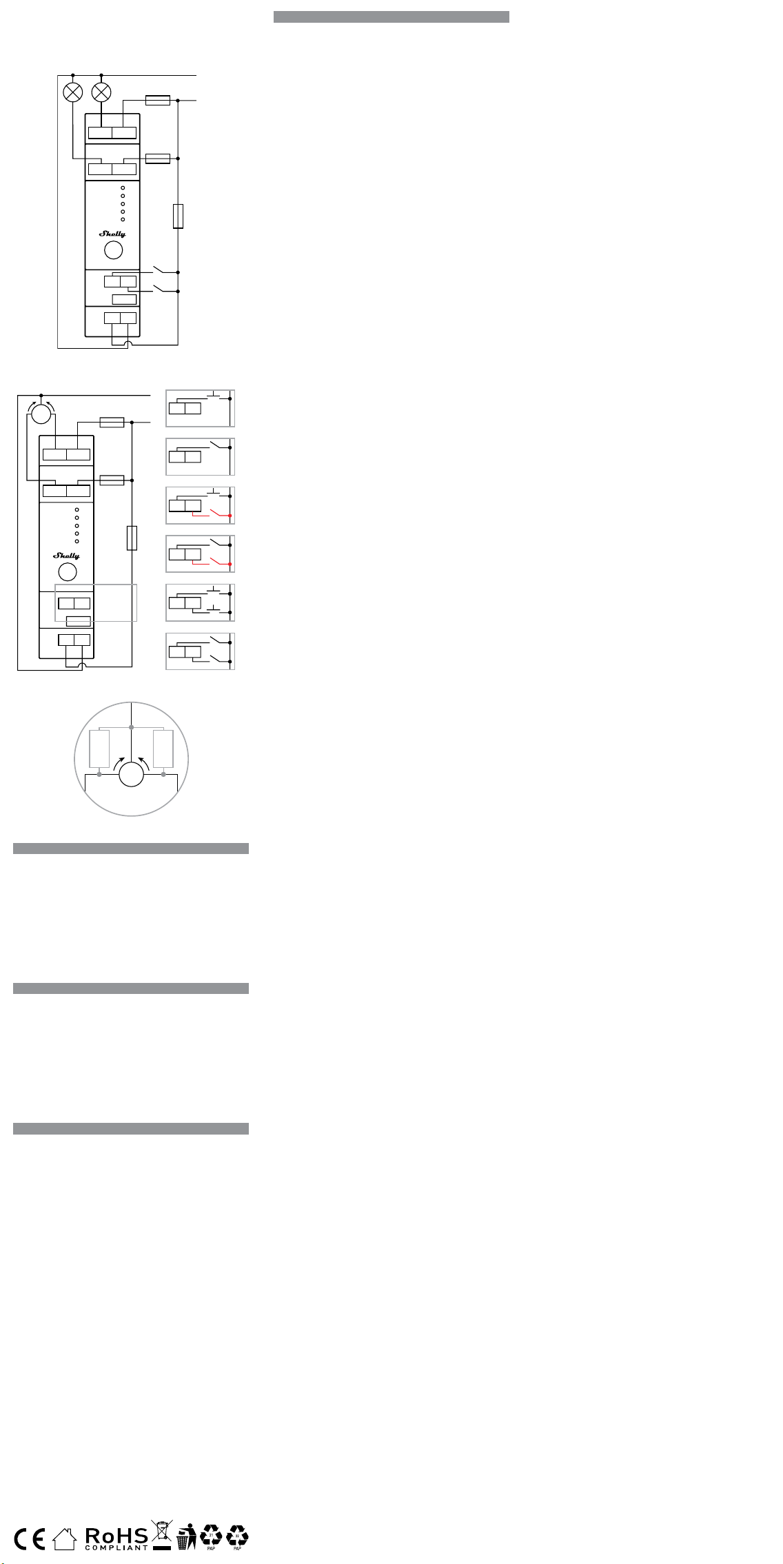
ES
GUÍA DE USO Y SEGURIDAD
RELÉ INTELIGENTE WI-FI DE 2 CIRCUITOS PARA
MONTAJE EN CARRIL DIN CON FUNCIONALIDAD
DE MEDICIÓN DE POTENCIA
SHELLY® PRO 2PM
Leia antes de utilizar
Este documento contém importante informação técnica e de
segurança relativa ao dispositivo, sua utilização segura e insta
-
lação.
⚠¡ATENCIÓN! Antes de iniciar a instalação, por favor leia aten-
tamente e na íntegra a documentação incluída. O incumprimento
dos procedimentos recomendados poderão dar origem a avarias,
perigo à sua vida ou violação da lei. A Allterco Robotics EOOD não
se responsabiliza por quaisquer perdas ou danos em caso de uma
incorreta instalação ou incorreta utilização deste dispositivo.
Resumen del producto
Shelly® es una gama de innovadores dispositivos basados en
microprocesadores que permiten controlar a distancia los electro-
domésticos a través de un teléfono móvil, una tableta, un PC o
un sistema domótico. Los dispositivos Shelly® pueden funcionar
de forma autónoma en una red Wi-Fi local o también pueden ser
operados por servicios de automatización del hogar a través del
Cloud. Shelly Cloud es un servicio que se puede utilizar a través
de la aplicación móvil Android o iOS, o a través de cualquier na-
vegador web en https://home.shelly.cloud/. Los dispositivos She-
lly® se pueden manejar, controlar y supervisar a distancia desde
cualquier lugar en el que el usuario disponga de una conexión a
Internet, siempre que los dispositivos estén conectados a un rou-
ter Wi-Fi y a Internet. Los dispositivos Shelly® tienen una interfaz
web integrada a la que se puede acceder en http://192.168.33.1
dentro de la red Wi-Fi, creada por el dispositivo en modo de punto
de acceso, o en la URL del dispositivo en la red Wi-Fi a la que está
conectado. La interfaz web integrada puede utilizarse para super-
visar y controlar el dispositivo y ajustar su conguración.
Los dispositivos Shelly® pueden comunicarse directamente con
otros dispositivos Wi-Fi a través de HTTP. Allterco Robotics EOOD
proporciona una API. Para más información, visite https://shelly-
api-docs.shelly.cloud/#shelly-family-overview.
Los dispositivos Shelly® vienen con el rmware instalado de fábri
-
ca. Si es necesario actualizar el rmware para que los dispositivos
sigan cumpliendo la normativa, incluidas las actualizaciones de
seguridad, Allterco Robotics EOOD proporcionará las actualiza-
ciones de forma gratuita a través de la interfaz web integrada en
el dispositivo o la aplicación móvil Shelly, donde está disponible
la información de la versión actual del rmware. La decisión de
instalar o no las actualizaciones del rmware del dispositivo es
responsabilidad exclusiva del usuario. Allterco Robotics EOOD no
se hace responsable de la falta de conformidad del Dispositivo
causada por el hecho de que el Usuario no instale oportunamente
las actualizaciones previstas.
Controla tu casa con tu voz
Los dispositivos Shelly® son compatibles con las funciones que
admiten Amazon Alexa y Google Home. Consulte nuestra guía
paso a paso en:
https://shelly.cloud/support/compatibility/.
Serie Shelly® Pro
La serie Shelly® Pro es una gama de dispositivos adecuados para
hogares, ocinas, tiendas minoristas, instalaciones de fabricación
y otros edicios. Los dispositivos Shelly® Pro pueden montarse en
DIN dentro de la caja de interruptores y son ideales para la cons
-
trucción de nuevos edicios. La conectividad de todos los disposi-
tivos Shelly® Pro puede ser a través de una conexión a Internet Wi-
Fi o LAN, y se puede utilizar Bluetooth para el proceso de inclusión.
Shelly® Pro 2PM (el dispositivo) es un relé inteligente de 2 circui-
tos para montaje en carril DIN con funciones de medición de po-
tencia y control de cobertura. Mejorado con la segunda generación
de exibilidad de rmware y conectividad LAN, proporciona a los
integradores profesionales muchas más opciones para las solu
-
ciones de los clientes nales.
Esquema - A la izquierda
Instrucciones de instalación
⚠¡ATENCIÓN! Peligro de descarga eléctrica. El montaje/instala-
ción del aparato a la red eléctrica debe ser realizado con cuidado,
por un electricista cualicado.
⚠¡ATENCIÓN! Peligro de descarga eléctrica. Cualquier modica-
ción de las conexiones debe realizarse después de asegurarse de
que no hay tensión en los terminales del Dispositivo.
⚠¡ATENCIÓN! Utilice el dispositivo sólo con una fuente de alimen-
tación y un equipo que cumplan con todas las normas aplicables.
Un cortocircuito en la red eléctrica o en cualquier dispositivo conec-
tado al aparato puede dañar el aparato.
⚠¡ATENCIÓN! No conecte el aparato a dispositivos que superen la
carga máxima indicada.
⚠¡ATENCIÓN! Conecte el aparato sólo de la manera indicada en
estas instrucciones. Cualquier otro método puede causar daños
y/o lesiones.
⚠¡ATENCIÓN! No instale el aparato en un lugar donde pueda mo
-
jarse.
⚠¡ATENCIÓN! Deje al menos 10 mm de espacio alrededor de cada
dispositivo Pro si espera corrientes superiores a 5 A por canal.
⚠¡Recomendación! Conecte el aparato con cables monoconduc-
tores sólidos con una resistencia térmica del aislamiento superior
a la del PVC T105°C.
Antes de iniciar la instalación/montaje del aparato, compruebe
que los disyuntores están desconectados y que no hay tensión
en sus bornes. Esto puede hacerse con un medidor de fase o un
multímetro. Cuando esté seguro de que no hay tensión, puede pro-
ceder a conectar los cables.
Si desea utilizar el Shelly® Pro 2PM como un relé de 2 circuitos,
conecte el terminal N al cable de Neutro y el terminal L al interrup
-
tor de alimentación del dispositivo como se muestra en la Img. 1.
Conecte el primer circuito de carga al borne O1 y al cable de Neu
-
tro. Conecte el terminal I1 al primer disyuntor de carga.
Conecte el segundo circuito de carga al terminal O2 y al cable Neu-
tro. Conecte el terminal I2 al segundo disyuntor de carga.
Conecte los dos interruptores/botones a los terminales S1 y S2 y
al disyuntor de alimentación del dispositivo.
⚠¡CUIDADO! Utilice una y la misma fase para ambos circuitos de
carga y el circuito de alimentación del Dispositivo.
⚠RECOMENDACIÓN: En el caso de los aparatos inductivos que
provocan picos de tensión durante el encendido y el apagado, como
los motores eléctricos, los ventiladores, las aspiradoras y otros si-
milares, debe conectarse un amortiguador RC (0,1µF / 100 Ω / 1/2
W / 600 VAC) en paralelo al aparato. El amortiguador RC se puede
adquirir en
https://shop.shelly.cloud/rc-snubber-wi-smart-home-automation
.
Como controlador de cubierta, Shelly® Pro2PM puede funcionar
en 3 modos: desconectado, con una sola entrada o con dos en
-
tradas.
En el modo separado, el dispositivo puede ser controlado a través
de su interfaz Web y la App solamente. Incluso si los botones o
interruptores están conectados al dispositivo, no podrán controlar
la rotación del motor en el modo independiente, pero pueden ser
utilizados para las acciones de la URL.
Si desea utilizar el dispositivo en modo desconectado, conecte el
dispositivo como se muestra en la Img. 2 a). Conecte el borne N al
cable neutro y el borne L al interruptor de alimentación del Dispo-
sitivo. Conecte el terminal/cable común del motor al cable Neutro.
Conecte los terminales/cables de dirección del motor a los termi-
nales O1 y O2*. Conecte el terminal I1 a uno de los disyuntores y el
terminal I2 al otro disyuntor.
Si desea utilizar el dispositivo en modo de entrada única, conecte
el dispositivo como se muestra en la Img. 2 b) para una entrada de
botón o en la Img. 2 c) para una entrada de interruptor. Conecte
el borne N al cable neutro y el borne L al disyuntor de alimenta
-
ción del Dispositivo. Conecte el terminal/cable común del motor
al cable Neutro. Conecte los terminales/cables de dirección del
motor a los terminales O1 y O2*. Conecte el terminal I1 a uno de
los disyuntores y el terminal I2 al otro disyuntor.
Conecte el pulsador o el interruptor al terminal S1 y al interruptor
de alimentación del dispositivo.
Si la entrada está congurada como botón en los ajustes del dis
-
positivo, cada pulsación del botón realiza un ciclo de apertura,
parada, cierre, parada etc.
Si la entrada está congurada como un interruptor, cada pulsación
del interruptor realiza un ciclo de apertura, parada, cierre, parada
etc.
PT
GUIA DO UTILIZADOR E DE SEGURANÇA
RELÉ DE 2 CIRCUITOS WI-FI INTELIGENTE DE
MONTAGEM DIN COM FUNCIONALIDADE DE
MEDIÇÃO DE ENERGIA
SHELLY® PRO 2PM
Leia antes de utilizar
Ce document contient des informations techniques et de sécurité
importantes concernant l’appareil, son utilisation et son installa
-
tion en toute sécurité.
⚠ATENÇÃO! Avant de commencer l’installation, veuillez lire atten-
tivement et complètement la documentation d’accompagnement.
Le non-respect des procédures recommandées peut entraîner un
dysfonctionnement, un danger pour votre vie ou une violation de
la loi. Allterco Robotics EOOD n’est pas responsable des pertes ou
des dommages en cas d’installation ou d’utilisation incorrecte de ce
dispositif.
Apresentação do Produto
Shelly® é uma linha de dispositivos inovadores geridos por micro-
-processador, que permitem o controlo remote de eletrodomésticos
através de telemóvel, tablet, PC ou sistema de domótica. Os disposi-
tivos Shelly® podem funcionar isoladamente numa rede Wi-Fi local
ou podem também ser operados através de serviços de domótica
em nuvem. Shelly Cloud é um desses serviços que pode ser acedido
usando uma aplicação móvel Android ou iOS, ou com um qualquer
browser de internet em https://home.shelly.cloud/. Os dispositivos
Shelly® podem ser acedidos, controlados e monitorizados remota-
mente a partir de qualquer localização onde o Utilizador tiver uma
conexão à internet, desde que os dispositivos estejam conectados
a um router Wi-Fi e à Internet. Os dispositivos Shelly® possuem um
Interface Web embutido e acessível em http://192.168.33.1 na rede
Wi-Fi, criada pelo dispositivo em modo Ponto de Acesso (AP), ou no
endereço URL do dispositivo na rede Wi-Fi a que está ligado. O Inter-
face Web embutido pode ser usado para monitorizar e controlar o
dispositivo, assim como ajustar as suas congurações.
Os dispositivos Shelly® podem comunicar diretamente com outros
dispositivos Wi-Fi através do protocolo HTTP. Uma App é fornecida
por Allterco Robotics EOOD. Para mais informação, por favor visite:
https://shelly-api-docs.shelly.cloud/#shelly-family-overview.
Os dispositivos Shelly® são distribuidos com rmware instalado em
fábrica. Se forem necessárias atualizações ao rmware de forma a
manter os dispositivos em conformidade, incluindo atualizações
de segurança, Allterco Robotics EOOD fornecerá as atualizações
gratuitamente através do Interface Web embutido ou da Aplicação
Móvel Shelly, onde a informação sobre a versão de rmware atual
se encontra acessível. A escolha em instalar ou não instalar as atua-
lizações de rmware do Dispositivo é responsabilidade única do uti-
lizador. Allterco Robotics EOOD não se responsabiliza por qualquer
falha na conformidade do Dispositivo causada pela não instalação
das atualizações disponíveis em tempo útil, por parte do Utilizador.
Controle a sua casa com a sua voz.
Os dispositivos Shelly® são compatíveis com as funcionalidades
suportadas por Amazon Alexa e Google Home. Por favor consulte
o nosso guia passo-a-passo em:
https://shelly.cloud/support/compatibility/.
Série Shelly® Pro
A Série Shelly® Pro é uma linha de dispositivos adequados a casas,
escritórios, lojas, instalações fabris e outros edifícios. Os dispositi-
vos Shelly® Pro são compatíveis com montagem DIN dentro de cai-
xas de disjuntores e de distribuição, e adequados à construção de
novos edifícios. A conetividade para todos os dispositivos Shelly®
Pro pode ser conseguida por meio de coneção de internet Wi-Fi ou
LAN, e Bluetooth pode ser usado no processo de integração.
Shelly® Pro 2PM (o Dispositivo) é um relé de 2 circuitos inteligente
de montagem em calhas DIN com funcionalidades de medição de
energia e controlo de coberturas. Aperfeiçoado com a exibilidade
do rmware de segunda geração e a conectividade LAN, fornece
assim muitas mais opções aos prossionais para soluções de
cliente nal.
Esquema - Para a esquerda
Instruções de Instalação
⚠ATENÇÃO! Perigo de eletrocussão. A montagem/instalação do
Dispositivo à rede elétrica deve ser executada com precaução, por
um eletricista qualicado.
⚠ATENÇÃO! Perigo de eletrocussão. Qualquer alteração nas liga-
ções só deve ser executada depois de assegurado de que não existe
qualquer voltagem nos terminais do Dispositivo.
⚠ATENÇÃO! Utilize o Dispositivo apenas com uma rede elétrica e
eletrodomésticos que estejam de acordo com os regulamentos apli-
cáveis. Um curto-circuito na rede elétrica ou num dos eletrodomésti-
cos conectados poderá danicar o Dispositivo.
⚠ATENÇÃO! Não conecte o Dispositivo a electrodomésticos se
estes excederem a carga máxima permitida.
⚠ATENÇÃO! Conecte o Dispositivo apenas da forma ilustrada
nestas instruções. Qualquer outra forma poderá causar danos e/ou
acidentes.
⚠ATENÇÃO! Não instale o dispositivo num local que possa car
molhado.
⚠CUIDADO! Deixe pelo menos 10 mm de espaço ao redor de cada
dispositivo Pro se você espera correntes superiores a 5 A por canal.
⚠RECOMENDAÇÃO Conecte o Dispositivo usando cabos de núcleo
unilar com isolamento em PVC resistente ao calor não inferior a
T105°C.
Antes de iniciar a montagem/instalação do Dispositivo, certique
-
-se de que os disjuntores estão desligados e de que não existe qual-
quer voltagem nos seus terminais. Isto pode ser vericado com um
multímetro ou medidor de fase. Assim que se certicar de que não
existe qualquer voltagem, poderá então proceder com a cablagem.
Se pretende utilizar o Shelly® Pro 2PM como relé de 2 circuitos,
conecte o terminal N ao cabo Neutro e o terminal L ao disjuntor do
circuito de alimentação do Dispositivo, tal como ilustrado na Fig. 1.
Conecte o primeiro circuito em carga ao terminal O1 e ao cabo
Neutro. Conecte o terminal I1 ao disjuntor do primeiro circuito em
carga. Conecte o segundo circuito em carga ao terminal O2 e ao
cabo Neutro. Conecte o terminal I2 ao disjuntor do segundo circuito
em carga.
Conecte os dois comutadores/interruptores aos terminais S1 e S2
e ao disjuntor do circuito de fonte de alimentação do Dispositivo.
⚠ATENÇÃO! Utilize uma única fase para ambos os circuitos em
carga e o circuito de alimentação do Dispositivo.
⚠RECOMENDAÇÃO: Na utilização com electrodomésticos de in
-
dutância que possam causar picos de tensão ao ligar/desligar, tais
como motores elétricos, ventoínhas, aspiradores e similares, um
Snubber RC (0.1µF / 100 Ω / 1/2 W / 600 VCA) deve ser conectado
em paralelo com o electrodoméstico. O Snubber RC pode ser adqui-
rido em:
https://shop.shelly.cloud/rc-snubber-wi-smart-home-automation
.
Como controlador de cobertura, o Shelly® Pro2PM pode funcionar
em 3 modos: “desanexado”, “entrada única” ou “entrada dupla”.
Em modo “desanexado”, o Dispositivo só poderá ser controlado
através da sua Web embutido ou da App. Mesmo que existam in-
terruptores ou comutadores conectados ao Dispositivo, estes não
podem controlar a rotação do motor em modo “desanexado” mas
podem ser utilizados para ações URL.
Se pretende utilizar o Dispositivo em modo “desanexado”, conecte
o Dispositivo como ilustrado na Fig. 2 a). Conecte o terminal N ao
cabo Neutro e o terminal L ao disjuntor do circuito de alimentação
do Dispositivo. Conecte o terminal/cabo comum do motor ao cabo
Neutro. Conecte os terminais/cabos de direção do motor aos ter-
minais O1 e O2*. Conecte o terminal I1 a um dos disjuntores e o
terminal I2 ao outro disjuntor.
Se pretende utilizar o Dispositivo em modo “entrada única”, conecte
o Dispositivo como ilustrado na Fig. 2 b) para entrada de interruptor
de botão ou Fig. 2 c) para entrada de comutador. Conecte o terminal
N ao cabo Neutro e o terminal L ao disjuntor do circuito de alimen-
tação do Dispositivo. Conecte o termina/cabo comum do motor ao
cabo Neutro. Conecte os terminais/cabos de direção do motor aos
terminais O1 e O2*. Conecte o terminal I1 a um dos disjuntores e o
terminal I2 ao outro disjuntor.
Conecte o botão interruptor ou o comutador ao terminal S1 e ao
disjuntor do circuito de alimentação do Dispositivo.
Se a entrada estiver denida como botão nas congurações do
Dispositivo, cada pressão do botão alterna entre abre, pára, fecha,
pára etc.
Se a entrada estiver denida como comutador, cada comutação
alterna entre abre, pára, fecha, pára etc.
Em modo “entrada única”, Shelly® Pro 2PM fornece a funcionalida
-
de de interrupção de segurança. Para a utilizar, conecte o Dispositi-
FR
GUIDE D’UTILISATION ET DE SÉCURITÉ
RELAIS INTELLIGENT WI-FI À 2 CIRCUITS
MONTABLE SUR RAIL DIN AVEC
FONCTIONNALITÉ DE MESURE DE PUISSANCE
SHELLY® PRO 2PM
A lire avant utilisation
Ce document contient des informations techniques et de sécurité
importantes concernant l’appareil, son utilisation et son installation
en toute sécurité.
⚠ATTENTION! Avant de commencer l’installation, veuillez lire atten
-
tivement et complètement la documentation d’accompagnement. Le
non-respect des procédures recommandées peut entraîner un dysfonc-
tionnement, un danger pour votre vie ou une violation de la loi. Allterco
Robotics EOOD n’est pas responsable des pertes ou des dommages en
cas d’installation ou d’utilisation incorrecte de ce dispositif.
Présentation du produit
Shelly® est une gamme de dispositifs innovants gérés par micropro-
cesseur, qui permettent de contrôler à distance les appareils élec-
triques par le biais d’un téléphone mobile, d’une tablette, d’un PC ou
d’un système domotique. Les dispositifs Shelly® peuvent fonctionner
de manière autonome sur un réseau local Wi-Fi ou ils peuvent éga-
lement être exploités par des services domotiques via Cloud. Shelly
Cloud est un service utilisable via l’application mobile Android ou iOS,
ou via n’importe quel navigateur Internet sur https://home.shelly.
cloud/. Les dispositifs Shelly® peuvent être utilisés, contrôlés et
surveillés à distance depuis n’importe quel endroit où l’utilisateur dis
-
pose d’une connexion Internet, à condition que les dispositifs soient
connectés à un routeur Wi-Fi et à Internet. Les dispositifs Shelly® ont
une interface Web intégrée accessible sur http://192.168.33.1 au
sein du réseau Wi Fi, créé par le dispositif en mode point d’accès, ou à
l’adresse URL du dispositif sur le réseau Wi-Fi auquel il est connecté.
L’interface Web intégrée peut être utilisée pour surveiller et contrôler
le dispositif, ainsi que pour ajuster ses paramètres.
Les dispositifs Shelly® peuvent communiquer directement avec
d’autres dispositifs Wi-Fi par le biais du protocole HTTP. Une API est
fournie par Allterco Robotics EOOD. Pour plus d’informations, veuillez
visiter:
https://shelly-api-docs.shelly.cloud/#shelly-family-overview.
Les dispositifs Shelly® sont livrés avec un micrologiciel installé en
usine. Si des mises à jour du micrologiciel sont nécessaires pour
maintenir les dispositifs en conformité, y compris des mises à jour
de sécurité, Allterco Robotics EOOD fournira les mises à jour gratuite-
ment via l’interface Web intégrée au dispositif ou l’application mobile
Shelly, où les informations sur la version actuelle du micrologiciel
sont disponibles. Le choix d’installer ou non les mises à jour du mi-
crologiciel du dispositif relève de la seule responsabilité de l’Utilisa-
teur. Allterco Robotics EOOD ne sera pas responsable de tout manque
de conformité du Dispositif causé par le fait que l’Utilisateur n’a pas
installé les mises à jour fournies en temps voulu.
Contrôlez votre maison avec votre voix
Les dispositifs Shelly® sont compatibles avec les fonctionnalités
prises en charge par Amazon Alexa et Google Home. Veuillez consul-
ter notre guide étape par étape sur:
https://shelly.cloud/support/compatibility/.
Série Shelly® Pro
La série Shelly® Pro est une gamme de dispositifs adaptés aux
maisons, bureaux, magasins de détail, installations de fabrication et
autres bâtiments. Les dispositifs Shelly® Pro peuvent être montés
en DIN à l’intérieur du boîtier de disjoncteurs et conviennent parfaite-
ment à la construction de nouveaux bâtiments. La connectivité pour
tous les dispositifs Shelly® Pro peut se faire par connexion Internet
Wi-Fi ou LAN, et Bluetooth peut être utilisé pour le processus d’inclu
-
sion.
Shelly® Pro 2PM (l’Appareil) est un relais intelligent à 2 circuits, mon-
table sur rail DIN, doté de fonctionnalités de mesure de la puissance
et de contrôle du couvercle. Amélioré par la exibilité du micrologiciel
de deuxième génération et la connectivité LAN, il offre aux intégra-
teurs professionnels beaucoup plus d’options pour les solutions des
clients naux.
Schéma - À gauche
Instructions d’installation
⚠ATTENTION! Danger d’électrocution. Le montage/installation de
l’Appareil sur le réseau électrique doit être effectué avec prudence, par
un électricien qualié.
⚠ATTENTION! Danger d’électrocution. Chaque modication des
connexions doit être effectuée après s’être assuré de l’absence de ten-
sion aux bornes du Dispositif.
⚠ATTENTION! N’utilisez l’Appareil qu’avec un réseau électrique et
des appareils conformes à toutes les réglementations applicables. Un
court-circuit sur le réseau électrique ou tout appareil connecté à l’Appa
-
reil peut endommager l’Appareil.
⚠ATTENTION! Ne connectez pas l’Appareil à des appareils dépas
-
sant la charge maximale indiquée !
⚠ATTENTION! Connectez l’Appareil uniquement de la manière indi-
quée dans ces instructions. Toute autre méthode pourrait causer des
dommages et/ou des blessures.
⚠ATTENTION! N’installez pas l’appareil à un endroit où il est pos
-
sible qu’il se mouille.
⚠ATTENTION! Prévoyez au moins 10 mm d’espace autour de chaque
appareil Pro si vous prévoyez des courants supérieurs à 5 A par canal.
⚠RECOMMANDATION! Connectez l’appareil à l’aide de câbles mo-
noconducteurs solides dont la résistance à la chaleur de l’isolation est
supérieure à celle du PVC T105°C.
Avant de commencer l’installation / le montage de l’appareil, vériez
que les disjoncteurs sont éteints et qu’il n’y a pas de tension sur leurs
bornes. Ceci peut être fait avec un phasemètre ou un multimètre.
Lorsque vous êtes sûr qu’il n’y a pas de tension, vous pouvez procéder
au raccordement des câbles.
«Si vous voulez utiliser le Shelly® Pro 2PM comme un relais à 2 cir-
cuits, connectez la borne N au câble Neutre et la borne L au disjonc-
teur d’alimentation de l’appareil comme indiqué sur la Fig. 1.
Connecter le premier circuit de charge à la borne O1 et au câble
Neutre. Connectez la borne I1 au disjoncteur du premier circuit de
charge.
Connectez le deuxième circuit de charge à la borne O2 et au câble
Neutre. Connectez la borne I2 au second disjoncteur de charge.
Connectez les deux interrupteurs/boutons aux bornes S1 et S2 et au
disjoncteur d’alimentation de l’appareil.
⚠CAUTION ! Utilisez une seule et même phase pour les deux circuits
de charge et le circuit d’alimentation de l’Appareil.
⚠RECOMMANDATION : Pour les appareils inductifs qui provoquent
des pics de tension lors de la mise en marche/arrêt, tels que les mo-
teurs électriques, les ventilateurs, les aspirateurs et similaires, un snub-
ber RC (0,1µF / 100 Ω / 1/2 W / 600 VAC) doit être connecté en parallèle
à l’appareil. Le snubber RC peut être acheté sur
https://shop.shelly.cloud/rc-snubber-wi-smart-home-automation
.
En tant que contrôleur de couverture, Shelly® Pro2PM peut fonction-
ner selon 3 modes : détaché, à une seule entrée ou à deux entrées.
En mode détaché, l’appareil peut être contrôlé uniquement via son
interface Web et l’application. Même si des boutons ou des inter
-
rupteurs sont connectés à l’Appareil, ils ne pourront pas contrôler la
rotation du moteur en mode détaché, mais ils peuvent être utilisés
pour des actions URL.
Si vous voulez utiliser le dispositif en mode détaché, connectez le
dispositif comme indiqué sur l’Img. 2 a). Connectez la borne N au
câble neutre et la borne L au disjoncteur d’alimentation du disposi-
tif. Connecter la borne/câble commune du moteur au câble Neutre.
Connectez les bornes/câbles de direction du moteur aux bornes O1
et O2*. Connectez la borne I1 à l’un des disjoncteurs et la borne I2 à
l’autre disjoncteur.
Si vous voulez utiliser le dispositif en mode d’entrée unique, connec-
tez le dispositif comme indiqué sur l’Img. 2 b) pour une entrée de bou-
ton ou l’Img. 2 c) pour une entrée d’interrupteur. Connectez la borne N
au câble Neutre et la borne L au disjoncteur d’alimentation du dispo-
sitif. Connecter la borne/câble commune du moteur au câble Neutre.
Connectez les bornes/câbles de direction du moteur aux bornes O1
et O2*. Connectez la borne I1 à l’un des disjoncteurs et la borne I2 à
l’autre disjoncteur.
Connectez le bouton ou l’interrupteur à la borne S1 et au disjoncteur
de l’alimentation du Dispositif.
Si l’entrée est congurée comme un bouton dans les paramètres du
dispositif, chaque pression sur le bouton entraîne l’ouverture, l’arrêt,
la fermeture, l’arrêt etc.
Si l’entrée est congurée comme un interrupteur, chaque bascule-
ment de l’interrupteur entraîne l’ouverture, l’arrêt, la fermeture, l’arrêt
etc.
En mode entrée unique, le Shelly® Pro 2PM offre une fonctionnali-
En el modo de entrada simple, Shelly® Pro 2PM ofrece la funciona-
lidad de interruptor de seguridad. Para utilizarla, conecte el dispo-
sitivo como se muestra en la Img. 2 d) para una entrada de botón o
en la Img. 2 e) para una entrada de interruptor. Conecte el terminal
N al cable neutro y el terminal L al interruptor de alimentación del
dispositivo. Conecte el terminal/cable común del motor al cable
Neutro. Conecte los terminales/cables de dirección del motor a los
terminales O1 y O2*. Conecte el terminal I1 a uno de los disyunto-
res y el terminal I2 al otro disyuntor.
Conecte el botón o interruptor de control al terminal S1 y al disyun-
tor de alimentación del dispositivo. Conecte el interruptor de segu-
ridad al terminal S2 y al disyuntor de alimentación del dispositivo.
El interruptor de seguridad puede ser congurado para:
- Detener el movimiento hasta que se desactive el interruptor de
seguridad o hasta que se envíe un comando** y, si está permitido
en la conguración del Dispositivo, se reanude el movimiento en la
dirección opuesta hasta alcanzar la posición nal.
Detener e invertir inmediatamente El movimiento hasta alcanzar la
posición nal. Esta opción requiere que se permita El movimiento
inverso en los ajustes del dispositivo.
El interruptor de seguridad también puede congurarse para de-
tener el movimiento sólo en una de las direcciones o en ambas.
Si desea utilizar el Dispositivo en modo de doble entrada, conecte
el dispositivo como se muestra en la Img. 2 f) para una entrada de
botón o en la Img. 2 g) para una entrada de interruptor. Conecte
el borne N al cable neutro y el borne L al interruptor de alimenta-
ción del Dispositivo. Conecte el terminal/cable común del motor
al cable Neutro. Conecte los terminales/cables de dirección del
motor a los terminales O1 y O2*. Conecte el terminal I1 a uno de
los disyuntores y el terminal I2 al otro disyuntor.
Conecte el primer pulsador o interruptor al terminal S1 y al disyun-
tor de alimentación del aparato. Conecte el segundo pulsador o
interruptor al terminal S2 y al disyuntor de alimentación del dis-
positivo.
En caso de que las entradas estén conguradas como botones:
- Pulsando un botón cuando la tapa está estática, se mueve la tapa
en la dirección correspondiente hasta alcanzar el punto nal.
- Presionando el botón para la misma dirección mientras la cubier-
ta está en movimiento, detiene la cubierta.
- Presionando el botón para la dirección opuesta, mientras la cu-
bierta se está moviendo, invierte el movimiento de la cubierta has-
ta alcanzar el punto nal.
En caso de que las entradas estén conguradas como interrup-
tores:
la activación de un interruptor mueve la cubierta en la dirección
correspondiente hasta alcanzar un punto nal.
Al apagar el interruptor, se detiene el movimiento de la tapa.
Si ambos interruptores están activados, el Shelly® Pro 2PM res-
petará el último interruptor activado. La desactivación del último
interruptor activado detiene el movimiento de la cubierta, incluso
si el otro interruptor sigue encendido. Para mover la cubierta en
la dirección opuesta, el otro interruptor tiene que ser apagado y
encendido de nuevo.
El Shelly® Pro 2PM puede detectar obstáculos. Si hay un obstácu-
lo, el movimiento de la cubierta se detendrá y, si se ha congurado
así en los ajustes del dispositivo, se invertirá hasta que se alcance
el punto nal. La detección de obstáculos puede ser activada o
desactivada sólo para una de las direcciones o para ambas.
⚠RECOMENDACIÓN: Para evitar picos de tensión durante el en-
cendido/apagado del motor bidireccional de la cubierta, deben co-
nectarse dos amortiguadores RC (0,1µF / 100Ω / 1/2W / 600V AC)
entre el común y los dos terminales/cables de dirección del motor
de la cubierta, como se muestra en la Img. 3.
Los snubbers RC se pueden adquirir en
https://shop.shelly.cloud/rc-snubber-wi-smart-home-automation
Inclusión inicial
Si decide utilizar el Dispositivo con la aplicación móvil Shelly Cloud
y el servicio Shelly Cloud, las instrucciones para conectar el Dispo
-
sitivo al Cloud y controlarlo a través de la App Shelly se encuen-
tran en la “Guía de la App”. La aplicación móvil Shelly y el servicio
Shelly Cloud no son condiciones para el buen funcionamiento del
Dispositivo. Este dispositivo puede utilizarse con otros servicios y
aplicaciones de domótica.
⚠¡ATENCIÓN! No permita que los niños jueguen con los botones/
interruptores conectados al aparato. Mantenga los dispositivos que
permiten el control remoto de Shelly (teléfonos móviles, tabletas,
ordenadores) fuera del alcance de los niños.
Indicación LED
• Power (rojo): El indicador de luz roja se encenderá si la fuente
de alimentación está conectada.
• Wi-Fi (varía):
- El indicador de luz azul se encenderá si está en modo AP.
- El indicador de luz roja se encenderá si está en modo STA y no
está conectado a una red Wi-Fi.
- El indicador de luz amarilla se encenderá si está en modo STA
y está conectado a una red Wi-Fi. No conectado a Shelly Cloud o
Shelly Cloud desactivado.
- El indicador de luz verde se encenderá si está en modo STA y
está conectado a una red Wi-Fi y a Shelly Cloud.
- El indicador luminoso estará parpadeando en rojo/azul si la
actualización OTA está en curso.
• LAN (verde): El indicador luminoso verde estará encendido si la
LAN está conectada.
• Out (rojo): El indicador luminoso rojo se encenderá si el relé de
salida está cerrado”
Botón de reinicio
• Manténgalo pulsado durante 5 segundos para el modo AP.
• Manténgalo pulsado durante 10 segundos para restablecer la
conguración de fábrica.
Especicaciones
• Montaje: Carril DIN
• Dimensiones (HxAxL): 68,5x18,5x89,5 mm
• Temperatura de trabajo: -20°C - 40°C
• Altitud máxima: 2000 m
• Alimentación: 110 - 240 VAC, 50/60Hz
• Consumo eléctrico: < 3 W
• Tensión de conmutación máxima: 240 VAC
• Corriente de conmutación máxima por canal 16 A
• Corriente total máxima en ambos canales: 25 A
• Potencia máxima de RF Wi-Fi: 13,34 dBm
• Protocolo de radio: Wi-Fi 802.11 b/g/n
• Frecuencia Wi-Fi: 2412 - 2472 МHz (máx. 2483 MHz)
• Alcance operativo (dependiendo de la construcción local)
- hasta 50 m en exteriores
- hasta 30 m en interiores
• Bluetooth: v.4.2
• Modulación Bluetooth: GFSK, π/4-DQPSK, 8-DPSK
• Frecuencia Bluetooth: TX/RX: 2402 - 2480MHz
• Potencia máxima de RF Bluetooth: 3,75 dBm
• LAN/Ethernet (RJ45): Sí
• Contactos secos: No
• Medición de potencia: Sí
• Protección contra sobrecarga: Sí
•
Protección contra sobrecorriente: Sí
• Protección contra sobretensión: Sí
• Protección contra sobretemperatura: Sí
• Scripting (mjs): Sí
• MQTT: SÍ
• Webhooks (acciones URL): 20 con 5 URLs por hook
• Horarios: 20
• CPU: ESP32
• Flash: 8 MB
Declaración de conformidad
Allterco Robotics EOOD declara por la presente que el equipo de
radio tipo Shelly Pro 1 cumple con las directivas 2014/53/UE,
2014/35/UE, 2014/30/UE, 2011/65/UE. El texto completo de la de-
claración de conformidad de la UE está disponible en la siguiente
dirección web
https://shelly.cloud/knowledge-base/devices/shelly-pro-2pm/
Fabricante: Allterco Robotics EOOD
Dirección: Bulgaria, Soa, 1407, 103 Cherni vrah Blvd.
Tel: +359 2 988 7435
Correo electrónico: support@shelly.cloud
Web ocial: https://www.shelly.cloud
Los cambios en la información de contacto son publicados por el
fabricante en el sitio web ocial del dispositivo
Todos los derechos de las marcas Shelly®, y otros derechos de
propiedad intelectual asociados a este dispositivo pertenecen a
Allterco Robotics EOOD.
vo como ilustrado na Fig. 2 d) para entrada de interruptor de botão
ou Fig. 2 e) para entrada de comutador. Conecte o terminal N ao
cabo Neutro e o terminal L ao disjuntor do circuito de alimentação
do Dispositivo. Conecte o terminal/cabo comum do motor ao cabo
Neutro. Conecte os terminais/cabos de direção do motor aos ter
-
minais O1 e O2*. Conecte o terminal I1 a um dos disjuntores e o
terminal I2 ao outro disjuntor.
Conecte o botão interruptor ou o comutador de controlo ao terminal
S1 e ao disjuntor do circuito de alimentação do Dispositivo. Conecte
o interruptor de segurança ao terminal S2 e ao disjuntor do circuito
de alimentação do Dispositivo.
O interruptor de segurança pode ser congurado para:
- Interromper o movimento até que o interruptor de segurança seja
desligado ou até que um comando seja enviado** e, se permitido
nas congurações do Dispositivo, o movimento seja retomado na
direção oposta até alcançar a posição nal.
- Interromper e reverter imediatamente o movimento até que a po-
sição nal seja alcançada. Esta opção requere que o movimento
inverso seja permitido nas congurações do Dispositivo.
O interruptor de segurança pode também ser congurado para inter-
romper o movimento numa direção ou ambas as direções.
Se pretende utilizar o Dispositivo em modo “entrada dupla”, conecte
o Dispositivo como ilustrado na Fig. 2 f) para entrada de interrupto-
res de botão ou Fig. 2 g) para entrada de comutadores. Conecte o
Terminal N ao cabo Neutro e o terminal L ao disjuntor do circuito
de alimentação do Dispositivo. Conecte o terminal/cabo comum
do motor ao cabo Neutro. Conecte os terminais/cabos de direção
do motor aos terminais O1 e O2*. Conecte o terminal I1 a um dos
disjuntores e o terminal I2 ao outro disjuntor.
Conecte o primeiro interruptor ou comutador ao terminal S1 e ao
disjuntor do circuito de alimentação do Dispositivo. Conecte o se-
gundo interruptor ou comutador ao terminal S2 e ao disjuntor do
circuito de alimentação do Dispositivo.
Caso as entradas estejam conguradas como botões interruptores:
- Pressionando um botão quando a cobertura está parada, move a
cobertura na direção correspondente até alcançar a posição nal.
- Pressionando o botão da mesma direção, enquanto a cobertura
está em movimento, a cobertura pára.
- Pressionando o botão da direção oposta, enquanto a cobertura
está em movimento, o reverte movimento até a posição nal ser
alcançada.
Caso as entradas estejam conguradas como comutadores inter-
ruptores:
- Ligando um interruptor, a cobertura move na direção correspon-
dente até que a posição nal seja alcançada.
- Desligando o interruptor, a cobertura interrompe o movimento.
Se ambos os interruptores forem ligados, Shelly® Pro 2PM respeita-
rá o último interruptor ligado. Desligando o último interruptor ligado,
interrompe o movimento da cobertura, mesmo que o outro interrup-
tor se mantenha ligado. Para mover a cobertura na direção oposta,
o outro interruptor terá de ser desligado e ligado novamente.
Shelly® Pro 2PM pode detetar obstáculos. Se um obstáculo esti-
ver presente, o movimento da cobertura é interrompido e, se assim
denido nas congurações do Dispositivo, revertido até alcançar a
posição nal. A deteção de obstáculos pode ser ativada ou desati-
vada para uma só direção ou para ambas as direções.
⚠RECOMENDAÇÃO: Para evitar picos de tensão ao ligar/desligar
o motor bi-direcional da cobertura, dois Snubbers RC (0.1µF / 100
Ω / 1/2 W / 600 VCA) devem ser conectados entre o comum e os
dois terminais/cabos de direção do motor da cobertura, tal como
ilustrado na Fig. 3.
Os Snubbers RC podem ser adquiridos em:
https://shop.shelly.cloud/rc-snubber-wi-smart-home-automation
Inclusão Inicial
Se escolher usar o Dispositivo com a aplicação móvel Shelly Cloud
e o serviço Shelly Cloud, instruções em como conectar o Disposi
-
tivo à Cloud e como controlá-lo através da App Shelly, podem ser
encontradas no “Guia da App”. A Shelly Mobile Application e o ser
-
viço Shelly Cloud não são condições únicas para o funcionamento
adequado do dispositivo. Este Dispositivo pode ser utilizado com
variadas aplicações e serviços de domótica.
⚠ATENÇÃO! Não permita que crianças brinquem com os botões/
comutadores conectados ao Dispositivo. Mantenha os Dispositivos
de controlo remoto do Shelly (telemóveis, tablets, PCs) fora do alcan
-
ce das crianças.
Indicação LED
• Energia (vermelho): Indicador de luz Vermelha estará ligado se
uma fonte de alimentação estiver conectada.
• Wi-Fi (variável):
- Indicador de luz Azul ligado se estiver em modo AP.
- Indicador de luz Vermelha ligado se estiver em modo STA e não
conectado a uma rede Wi-Fi.
- Indicador de luz Amarela ligado se estiver em modo STA e
conectado a uma rede Wi-Fi. Não conectado à Shelly Cloud ou
Shelly Cloud desativada.
- Indicador de luz Verde ligado se estiver em modo STA, conecta-
do a uma rede Wi-Fi e à Shelly Cloud.
- O indicador luminoso estará intermitente entre Vermelho/Azul
se uma atualização OTA estiver em progresso.
• LAN (verde): Indicador de luz Verde estará ligado se LAN estiver
conectada.
• Out (vermelho): Indicador de luz Vermelha estará ligado se a Saí-
da de relé estiver fechada.
Botão de reinicialização
• Pressione durante 5 segundos para modo AP.
• Pressione durante 10 segundos para conguração de fábrica.
Especicações
• Montagem: Calha DIN
• Dimensões (AxLxC): 68.5x18.5x89.5 mm
• Temperatura de funcionamento: -20°C - 40°C
• Altitude máxima: 2000 m
• Fonte de alimentação: 110 - 240 VAC, 50/60Hz
• Consumo elétrico: < 3 W
• Voltagem máxima de comutação: 240 VCA
• Corrente máxima de comutação: 16 A
• Corrente máxima total nos dois canais: 25 A
• Potência máxima de RF Wi-Fi: 13.34 dBm
• Protocolo de rádio: Wi-Fi 802.11 b/g/n
• Frequência Wi-Fi: 2412 - 2472 МHz (Max. 2483 MHz)
• Alcance de operação (dependendo da construção local):
- até 50 m no exterior,
- até 30 m no interior
• Bluetooth: v.4.2
• Modulação Bluetooth: GFSK, π/4-DQPSK, 8-DPSK
• Frequência Bluetooth: TX/RX - 2402 - 2480MHz
• Potência máxima de RF Bluetooth: 3.75 dBm
• LAN/Ethernet (RJ45): Sim
• Contatos secos: Não
• Medição de potência: Sim
• Proteção de sobrepotência: Sim
• Proteção de sobrecorrente: Sim
• Proteção de sobretensão: Sim
• Proteção de sobretemperatura: Sim
• Scripting (mjs): Sim
• MQTT: Sim
• Webhooks (ações URL): 20 com 5 URLs por cada “hook”
• Agendamentos: 20
• CPU: ESP32
• Flash: 8 MB
Declaração de conformidade
A Allterco Robotics EOOD declara por este meio que o equipa-
mento rádio tipo Shelly Pro 2 opera conforme a Diretriz 2014/53/
EU, 2014/35/EU, 2014/30/EU, 2011/65/EU. O texto completo da
declaração da UE sobre a conformidade está disponível no seguinte
endereço de internet
https://shelly.cloud/knowledge-base/devices/shelly-pro-2pm/
Fabricante: Allterco Robotics EOOD
Endereço: 1407, 103 Cherni vrah Blvd. Soa, Bulgária
Tel.: +359 2 988 7435
E-mail: support@shelly.cloud
Website ocial: https://www.shelly.cloud
Alterações nos endereços de contato são publicados pelo Fabrican-
te no website ocial do Dispositivo
Todos os direitos sobre a marca registada Shelly® e outros direitos
de propriedade intelectual associados a este Dispositivo pertencem
a Allterco Robotics EOOD.
té d’interrupteur de sécurité. Pour l’utiliser, connectez le dispositif
comme indiqué sur l’Img. 2 d) pour une entrée de bouton ou l’Img.
2 e) pour une entrée d’interrupteur. Connectez la borne N au câble
Neutre et la borne L au disjoncteur d’alimentation de l’appareil.
Connecter la borne/câble commune du moteur au câble Neutre.
Connectez les bornes/câbles de direction du moteur aux bornes O1
et O2*. Connectez la borne I1 à l’un des disjoncteurs et la borne I2 à
l’autre disjoncteur.
Connectez le bouton ou l’interrupteur de commande à la borne S1 et
au disjoncteur d’alimentation de l’appareil. Connectez l’interrupteur de
sécurité à la borne S2 et au disjoncteur d’alimentation de l’appareil.
L’interrupteur de sécurité peut être conguré pour :
- Arrêter le mouvement jusqu’à ce que l’interrupteur de sécurité soit
désengagé ou jusqu’à ce qu’une commande soit envoyée** et, si cela
est autorisé dans les paramètres du Dispositif, le mouvement est re-
pris dans la direction opposée jusqu’à ce que la po
- Arrêter et inverser immédiatement le mouvement jusqu’à ce que la
position nale soit atteinte. Cette option nécessite que le mouvement
inverse soit autorisé dans les paramètres du dispositif.
L’interrupteur de sécurité peut également être conguré pour arrêter le
mouvement dans une seule des directions ou dans les deux.
Si vous souhaitez utiliser le dispositif en mode d’entrée double,
connectez le dispositif comme indiqué sur l’Img. 2 f) pour les entrées
de bouton ou l’Img. 2 g) pour les entrées d’interrupteur. Connectez la
borne N au câble Neutre et la borne L au disjoncteur d’alimentation du
dispositif. Connecter la borne/câble commune du moteur au câble
Neutre. Connectez les bornes/câbles de direction du moteur aux
bornes O1 et O2*. Connectez la borne I1 à l’un des disjoncteurs et la
borne I2 à l’autre disjoncteur.
Connectez le premier bouton ou interrupteur à la borne S1 et au
disjoncteur d’alimentation de l’appareil. Connectez le deuxième bou-
ton ou interrupteur à la borne S2 et au disjoncteur d’alimentation du
dispositif.
Dans le cas où les entrées sont congurées comme des boutons :
- En appuyant sur un bouton lorsque le couvercle est statique, le cou-
vercle se déplace dans la direction correspondante jusqu’à ce que le
point nal soit atteint.
- Si l’on appuie sur le bouton dans la même direction alors que le cou-
vercle est en mouvement, le couvercle s’arrête.
- L’appui sur le bouton dans la direction opposée, alors que le cou-
vercle est en mouvement, inverse le mouvement du couvercle jusqu’à
ce que le point nal soit atteint.
Dans le cas où les entrées sont congurées comme des interrupteurs:
- La mise en marche d’un interrupteur déplace le couvercle dans la
direction correspondante jusqu’à ce qu’un point nal soit atteint.
- La mise hors tension de l’interrupteur arrête le mouvement du cou-
vercle.
Si les deux interrupteurs sont activés, le Shelly® Pro 2PM respectera
le dernier interrupteur engagé. Le fait de désactiver le dernier inter-
rupteur engagé arrête le mouvement du couvercle, même si l’autre
interrupteur est toujours activé. Pour déplacer le couvercle dans la
direction opposée, l’autre interrupteur doit être désactivé et réactivé.
Le Shelly® Pro 2PM peut détecter les obstacles. Si un obstacle est
présent, le mouvement du couvercle sera arrêté et, si cela est con-
guré dans les paramètres du dispositif, inversé jusqu’à ce que le point
nal soit atteint. La détection d’obstacles peut être activée ou désac-
tivée pour une seule des directions ou pour les deux.
⚠RECOMMANDATION : Pour éviter les pics de tension lors de la
mise en marche/arrêt du moteur bidirectionnel du couvercle, deux
snubbers RC (0,1µF / 100Ω / 1/2W / 600V AC) doivent être connectés
entre le commun et les bornes/câbles des deux directions du moteur
du couvercle, comme indiqué sur l’image 3.
Les snubbers RC peuvent être achetés sur
https://shop.shelly.cloud/rc-snubber-wi-smart-home-automation
Inclusion initiale
Si vous choisissez d’utiliser l’Appareil avec l’application mobile Shelly
Cloud et le service Shelly Cloud, les instructions pour connecter l’Ap-
pareil au Cloud et le contrôler via l’App Shelly se trouvent dans le «
Guide de l’App «. L’application mobile Shelly et le service Shelly Cloud
ne sont pas des conditions au bon fonctionnement de l’Appareil. Cet
Appareil peut être utilisé avec divers autres services et applications
domotiques.
⚠ATTENTION! Ne laissez pas les enfants jouer avec les boutons/
interrupteurs connectés à l’Appareil. Gardez les Dispositifs permettant
de contrôler Shelly à distance (téléphones mobiles, tablettes, PC) hors
de portée des enfants.
Indicateurs LED
• Alimentation (rouge) : L’indicateur lumineux rouge s’allume si l’ali-
mentation électrique est connectée.
• Wi-Fi (varie) :
- Le voyant bleu s’allume en mode AP.
- Le voyant rouge s’allume si l’appareil est en mode STA et n’est pas
connecté à un réseau Wi-Fi.
- Le voyant jaune s’allume si l’appareil est en mode STA et connecté
à un réseau Wi-Fi. Non connecté à Shelly Cloud ou Shelly Cloud
désactivé.
- Le voyant lumineux vert sera allumé si en mode STA et connecté
à un réseau Wi-Fi et au Shelly Cloud.
- L’indicateur lumineux clignotera en rouge/bleu si la mise à jour
OTA est en cours.
• LAN (vert) : L’indicateur lumineux vert sera allumé si le réseau local
est connecté.
• Sortie (rouge) : L’indicateur lumineux rouge sera allumé si le relais
de sortie est fermé.
Bouton de réinitialisation
• Appuyez et maintenez enfoncé pendant 5 secondes pour le mode
A P.
• Appuyez et maintenez enfoncé pendant 10 secondes pour réinitia-
liser les paramètres d’usine.
Caractéristiques techniques
• Montage : Rail DIN
• Dimensions (HxLxL) : 68,5x18,5x89,5 mm
• Température de fonctionnement : -20°C - 40°C
• Altitude maximale: 2000 m
• Alimentation électrique : 110 - 240 VAC, 50/60Hz
• Consommation électrique : < 3 W
• Tension de commutation maximale : 240 VAC
• Courant de commutation maximum par canal : 16 A
• Courant total maximum sur les deux canaux : 25 A
• Puissance RF maximale Wi-Fi: 13,34 dBm
• Protocole radio : Wi-Fi 802.11 b/g/n
• Fréquence Wi-Fi : 2412 - 2472 МHz (Max. 2483 MHz)
• Portée opérationnelle (en fonction de la construction locale) :
- jusqu’à 50 m à l’extérieur,
- jusqu’à 30 m à l’intérieur
• Bluetooth : v.4.2
• Modulation Bluetooth : GFSK, π/4-DQPSK, 8-DPSK
• Fréquence Bluetooth: TX/RX - 2402 - 2480MHz
• Puissance RF maximale Bluetooth: 3,75 dBm
• LAN/Ethernet (RJ45): Oui
• Contacts secs : Non
• Mesure de la puissance : Oui
• Protection contre les surpuissances : Oui
• Protection contre les surintensités : Oui
• Protection contre les surtensions : Oui
• Protection contre la surchauffe : Oui
• Scripting (mjs) : Oui
• MQTT : OUI
• Webhooks (actions URL) : 20 avec 5 URLs par hook
• Planications : 20
• CPU : ESP32
• Flash : 8 MB
Déclaration de conformité
Par la présente, Allterco Robotics EOOD déclare que l’équipement
radio de type Shelly Pro 2 est conforme à la directive 2014/53/UE,
2014/35/UE, 2014/30/UE, 2011/65/UE. Le texte complet de la dé-
claration de conformité de l’UE est disponible à l’adresse internet
suivante
https://shelly.cloud/knowledge-base/devices/shelly-pro-2pm/
Fabricant: Allterco Robotics EOOD
Adresse: Bulgarie, Soa, 1407, 103 Cherni vrah Blvd.
Tél: +359 2 988 7435
Email: support@shelly.cloud
Site ociel : https://www.shelly.cloud
Les modications des coordonnées sont publiées par le fabricant sur
le site ociel de l’appareil
Tous les droits sur les marques Shelly®, et autres droits intellectuels
associés à ce dispositif appartiennent à Allterco Robotics EOOD.
Esquema
Esquema
Schéma
L
N
O1 I1
O2 I2
LN
SW1SW2
LAN
Power
Wi-Fi
LAN
Out 1
Out 2
Reset
Fig. 1
L
N
O1
M
I1
O2 I2
LN
SW1SW2
LAN
Power
Wi-Fi
LAN
Out 1
Out 2
Reset
a)
SW1SW2
c)
SW1SW2
e)
SW1SW2
г)
SW1SW2
b)
SW1SW2
f)
SW1SW2
d)
Fig. 2
M
O2 O1
N
RC
Snubber
RC
Snubber
Fig. 3
ES
Leyenda
Terminales del dispositivo:
• O1, O2: Terminales de salida de carga
• I1, I2: Terminales de entrada de carga
• SW1, SW2: Terminales de entrada del interruptor que controla
O1 y O2
• L: Terminal de corriente (110-240 VAC)
• N: Terminal de neutro
• LAN: Red de área local Conector RJ 45
Cables:
• N: Cable neutro
• L: Cable vivo (110 - 240 VAC)
PT
Legenda
Terminais do dispositivo:
• O1, O2: Terminais de saída de carga
• I1, I2: Terminais de entrada de carga
• SW1, SW2: Terminais de interruptor de entrada controlando
O1 e O2
• L: Terminal de corrente (110-240 VCA)
• N: Terminal de Neutro
• LAN: Conector RJ 45 “Local Area Network”
Cabos:
• N: Cabo de Neutro
• L: Cabo de corrente (110-240 VCA)
FR
Légende
Bornes du dispositif :
• O1, O2 : Bornes de sortie de charge
• I1, I2 : Bornes d’entrée de charge
• SW1, SW2 : Bornes d’entrée de commutateur commandant O1
et O2
• L : Borne sous tension (110-240 VAC)
• N : Borne de neutre
• LAN : Réseau local connecteur RJ 45
Câbles :
• N : Câble neutre
• L : Câble sous tension (110 - 240 VAC)
25/2022
*Las salidas del dispositivo pueden ser reconguradas para que coincidan con el sentido de rotación requerido.
**Interacción con el botón, el interruptor o un control en la interfaz Webo en la App (tiene que comandar la cubierta en la dirección opuesta a
la de accionamiento del interruptor de seguridad)
* As saídas do Dispositivo podem ser reconguradas para a direção de rotação desejada.
** Interação com o interruptor, o comutador ou um controlo na Interface Web ou na App (tem de comandar a cobertura na direção oposta antes
de acionar o interruptor de segurança)
*Les sorties du dispositif peuvent être recongurées pour correspondre au sens de rotation requis.
**Interaction avec le bouton, l’interrupteur ou une commande dans l’interface Web ou dans l’application (doit commander le couvercle dans le
sens opposé à la direction avant l’enclenchement de l’interrupteur de sécurité)

ES
GUÍA DE USO Y SEGURIDAD
RELÉ INTELIGENTE WI-FI DE 2 CIRCUITOS PARA
MONTAJE EN CARRIL DIN CON FUNCIONALIDAD
DE MEDICIÓN DE POTENCIA
SHELLY® PRO 2PM
Leia antes de utilizar
Este documento contém importante informação técnica e de
segurança relativa ao dispositivo, sua utilização segura e insta
-
lação.
⚠¡ATENCIÓN! Antes de iniciar a instalação, por favor leia aten-
tamente e na íntegra a documentação incluída. O incumprimento
dos procedimentos recomendados poderão dar origem a avarias,
perigo à sua vida ou violação da lei. A Allterco Robotics EOOD não
se responsabiliza por quaisquer perdas ou danos em caso de uma
incorreta instalação ou incorreta utilização deste dispositivo.
Resumen del producto
Shelly® es una gama de innovadores dispositivos basados en
microprocesadores que permiten controlar a distancia los electro-
domésticos a través de un teléfono móvil, una tableta, un PC o
un sistema domótico. Los dispositivos Shelly® pueden funcionar
de forma autónoma en una red Wi-Fi local o también pueden ser
operados por servicios de automatización del hogar a través del
Cloud. Shelly Cloud es un servicio que se puede utilizar a través
de la aplicación móvil Android o iOS, o a través de cualquier na-
vegador web en https://home.shelly.cloud/. Los dispositivos She-
lly® se pueden manejar, controlar y supervisar a distancia desde
cualquier lugar en el que el usuario disponga de una conexión a
Internet, siempre que los dispositivos estén conectados a un rou-
ter Wi-Fi y a Internet. Los dispositivos Shelly® tienen una interfaz
web integrada a la que se puede acceder en http://192.168.33.1
dentro de la red Wi-Fi, creada por el dispositivo en modo de punto
de acceso, o en la URL del dispositivo en la red Wi-Fi a la que está
conectado. La interfaz web integrada puede utilizarse para super-
visar y controlar el dispositivo y ajustar su conguración.
Los dispositivos Shelly® pueden comunicarse directamente con
otros dispositivos Wi-Fi a través de HTTP. Allterco Robotics EOOD
proporciona una API. Para más información, visite https://shelly-
api-docs.shelly.cloud/#shelly-family-overview.
Los dispositivos Shelly® vienen con el rmware instalado de fábri
-
ca. Si es necesario actualizar el rmware para que los dispositivos
sigan cumpliendo la normativa, incluidas las actualizaciones de
seguridad, Allterco Robotics EOOD proporcionará las actualiza-
ciones de forma gratuita a través de la interfaz web integrada en
el dispositivo o la aplicación móvil Shelly, donde está disponible
la información de la versión actual del rmware. La decisión de
instalar o no las actualizaciones del rmware del dispositivo es
responsabilidad exclusiva del usuario. Allterco Robotics EOOD no
se hace responsable de la falta de conformidad del Dispositivo
causada por el hecho de que el Usuario no instale oportunamente
las actualizaciones previstas.
Controla tu casa con tu voz
Los dispositivos Shelly® son compatibles con las funciones que
admiten Amazon Alexa y Google Home. Consulte nuestra guía
paso a paso en:
https://shelly.cloud/support/compatibility/.
Serie Shelly® Pro
La serie Shelly® Pro es una gama de dispositivos adecuados para
hogares, ocinas, tiendas minoristas, instalaciones de fabricación
y otros edicios. Los dispositivos Shelly® Pro pueden montarse en
DIN dentro de la caja de interruptores y son ideales para la cons
-
trucción de nuevos edicios. La conectividad de todos los disposi-
tivos Shelly® Pro puede ser a través de una conexión a Internet Wi-
Fi o LAN, y se puede utilizar Bluetooth para el proceso de inclusión.
Shelly® Pro 2PM (el dispositivo) es un relé inteligente de 2 circui-
tos para montaje en carril DIN con funciones de medición de po-
tencia y control de cobertura. Mejorado con la segunda generación
de exibilidad de rmware y conectividad LAN, proporciona a los
integradores profesionales muchas más opciones para las solu
-
ciones de los clientes nales.
Esquema - A la izquierda
Instrucciones de instalación
⚠¡ATENCIÓN! Peligro de descarga eléctrica. El montaje/instala-
ción del aparato a la red eléctrica debe ser realizado con cuidado,
por un electricista cualicado.
⚠¡ATENCIÓN! Peligro de descarga eléctrica. Cualquier modica-
ción de las conexiones debe realizarse después de asegurarse de
que no hay tensión en los terminales del Dispositivo.
⚠¡ATENCIÓN! Utilice el dispositivo sólo con una fuente de alimen-
tación y un equipo que cumplan con todas las normas aplicables.
Un cortocircuito en la red eléctrica o en cualquier dispositivo conec-
tado al aparato puede dañar el aparato.
⚠¡ATENCIÓN! No conecte el aparato a dispositivos que superen la
carga máxima indicada.
⚠¡ATENCIÓN! Conecte el aparato sólo de la manera indicada en
estas instrucciones. Cualquier otro método puede causar daños
y/o lesiones.
⚠¡ATENCIÓN! No instale el aparato en un lugar donde pueda mo
-
jarse.
⚠¡ATENCIÓN! Deje al menos 10 mm de espacio alrededor de cada
dispositivo Pro si espera corrientes superiores a 5 A por canal.
⚠¡Recomendación! Conecte el aparato con cables monoconduc-
tores sólidos con una resistencia térmica del aislamiento superior
a la del PVC T105°C.
Antes de iniciar la instalación/montaje del aparato, compruebe
que los disyuntores están desconectados y que no hay tensión
en sus bornes. Esto puede hacerse con un medidor de fase o un
multímetro. Cuando esté seguro de que no hay tensión, puede pro-
ceder a conectar los cables.
Si desea utilizar el Shelly® Pro 2PM como un relé de 2 circuitos,
conecte el terminal N al cable de Neutro y el terminal L al interrup
-
tor de alimentación del dispositivo como se muestra en la Img. 1.
Conecte el primer circuito de carga al borne O1 y al cable de Neu
-
tro. Conecte el terminal I1 al primer disyuntor de carga.
Conecte el segundo circuito de carga al terminal O2 y al cable Neu-
tro. Conecte el terminal I2 al segundo disyuntor de carga.
Conecte los dos interruptores/botones a los terminales S1 y S2 y
al disyuntor de alimentación del dispositivo.
⚠¡CUIDADO! Utilice una y la misma fase para ambos circuitos de
carga y el circuito de alimentación del Dispositivo.
⚠RECOMENDACIÓN: En el caso de los aparatos inductivos que
provocan picos de tensión durante el encendido y el apagado, como
los motores eléctricos, los ventiladores, las aspiradoras y otros si-
milares, debe conectarse un amortiguador RC (0,1µF / 100 Ω / 1/2
W / 600 VAC) en paralelo al aparato. El amortiguador RC se puede
adquirir en
https://shop.shelly.cloud/rc-snubber-wi-smart-home-automation
.
Como controlador de cubierta, Shelly® Pro2PM puede funcionar
en 3 modos: desconectado, con una sola entrada o con dos en
-
tradas.
En el modo separado, el dispositivo puede ser controlado a través
de su interfaz Web y la App solamente. Incluso si los botones o
interruptores están conectados al dispositivo, no podrán controlar
la rotación del motor en el modo independiente, pero pueden ser
utilizados para las acciones de la URL.
Si desea utilizar el dispositivo en modo desconectado, conecte el
dispositivo como se muestra en la Img. 2 a). Conecte el borne N al
cable neutro y el borne L al interruptor de alimentación del Dispo-
sitivo. Conecte el terminal/cable común del motor al cable Neutro.
Conecte los terminales/cables de dirección del motor a los termi-
nales O1 y O2*. Conecte el terminal I1 a uno de los disyuntores y el
terminal I2 al otro disyuntor.
Si desea utilizar el dispositivo en modo de entrada única, conecte
el dispositivo como se muestra en la Img. 2 b) para una entrada de
botón o en la Img. 2 c) para una entrada de interruptor. Conecte
el borne N al cable neutro y el borne L al disyuntor de alimenta
-
ción del Dispositivo. Conecte el terminal/cable común del motor
al cable Neutro. Conecte los terminales/cables de dirección del
motor a los terminales O1 y O2*. Conecte el terminal I1 a uno de
los disyuntores y el terminal I2 al otro disyuntor.
Conecte el pulsador o el interruptor al terminal S1 y al interruptor
de alimentación del dispositivo.
Si la entrada está congurada como botón en los ajustes del dis
-
positivo, cada pulsación del botón realiza un ciclo de apertura,
parada, cierre, parada etc.
Si la entrada está congurada como un interruptor, cada pulsación
del interruptor realiza un ciclo de apertura, parada, cierre, parada
etc.
PT
GUIA DO UTILIZADOR E DE SEGURANÇA
RELÉ DE 2 CIRCUITOS WI-FI INTELIGENTE DE
MONTAGEM DIN COM FUNCIONALIDADE DE
MEDIÇÃO DE ENERGIA
SHELLY® PRO 2PM
Leia antes de utilizar
Ce document contient des informations techniques et de sécurité
importantes concernant l’appareil, son utilisation et son installa
-
tion en toute sécurité.
⚠ATENÇÃO! Avant de commencer l’installation, veuillez lire atten-
tivement et complètement la documentation d’accompagnement.
Le non-respect des procédures recommandées peut entraîner un
dysfonctionnement, un danger pour votre vie ou une violation de
la loi. Allterco Robotics EOOD n’est pas responsable des pertes ou
des dommages en cas d’installation ou d’utilisation incorrecte de ce
dispositif.
Apresentação do Produto
Shelly® é uma linha de dispositivos inovadores geridos por micro-
-processador, que permitem o controlo remote de eletrodomésticos
através de telemóvel, tablet, PC ou sistema de domótica. Os disposi-
tivos Shelly® podem funcionar isoladamente numa rede Wi-Fi local
ou podem também ser operados através de serviços de domótica
em nuvem. Shelly Cloud é um desses serviços que pode ser acedido
usando uma aplicação móvel Android ou iOS, ou com um qualquer
browser de internet em https://home.shelly.cloud/. Os dispositivos
Shelly® podem ser acedidos, controlados e monitorizados remota-
mente a partir de qualquer localização onde o Utilizador tiver uma
conexão à internet, desde que os dispositivos estejam conectados
a um router Wi-Fi e à Internet. Os dispositivos Shelly® possuem um
Interface Web embutido e acessível em http://192.168.33.1 na rede
Wi-Fi, criada pelo dispositivo em modo Ponto de Acesso (AP), ou no
endereço URL do dispositivo na rede Wi-Fi a que está ligado. O Inter-
face Web embutido pode ser usado para monitorizar e controlar o
dispositivo, assim como ajustar as suas congurações.
Os dispositivos Shelly® podem comunicar diretamente com outros
dispositivos Wi-Fi através do protocolo HTTP. Uma App é fornecida
por Allterco Robotics EOOD. Para mais informação, por favor visite:
https://shelly-api-docs.shelly.cloud/#shelly-family-overview.
Os dispositivos Shelly® são distribuidos com rmware instalado em
fábrica. Se forem necessárias atualizações ao rmware de forma a
manter os dispositivos em conformidade, incluindo atualizações
de segurança, Allterco Robotics EOOD fornecerá as atualizações
gratuitamente através do Interface Web embutido ou da Aplicação
Móvel Shelly, onde a informação sobre a versão de rmware atual
se encontra acessível. A escolha em instalar ou não instalar as atua-
lizações de rmware do Dispositivo é responsabilidade única do uti-
lizador. Allterco Robotics EOOD não se responsabiliza por qualquer
falha na conformidade do Dispositivo causada pela não instalação
das atualizações disponíveis em tempo útil, por parte do Utilizador.
Controle a sua casa com a sua voz.
Os dispositivos Shelly® são compatíveis com as funcionalidades
suportadas por Amazon Alexa e Google Home. Por favor consulte
o nosso guia passo-a-passo em:
https://shelly.cloud/support/compatibility/.
Série Shelly® Pro
A Série Shelly® Pro é uma linha de dispositivos adequados a casas,
escritórios, lojas, instalações fabris e outros edifícios. Os dispositi-
vos Shelly® Pro são compatíveis com montagem DIN dentro de cai-
xas de disjuntores e de distribuição, e adequados à construção de
novos edifícios. A conetividade para todos os dispositivos Shelly®
Pro pode ser conseguida por meio de coneção de internet Wi-Fi ou
LAN, e Bluetooth pode ser usado no processo de integração.
Shelly® Pro 2PM (o Dispositivo) é um relé de 2 circuitos inteligente
de montagem em calhas DIN com funcionalidades de medição de
energia e controlo de coberturas. Aperfeiçoado com a exibilidade
do rmware de segunda geração e a conectividade LAN, fornece
assim muitas mais opções aos prossionais para soluções de
cliente nal.
Esquema - Para a esquerda
Instruções de Instalação
⚠ATENÇÃO! Perigo de eletrocussão. A montagem/instalação do
Dispositivo à rede elétrica deve ser executada com precaução, por
um eletricista qualicado.
⚠ATENÇÃO! Perigo de eletrocussão. Qualquer alteração nas liga-
ções só deve ser executada depois de assegurado de que não existe
qualquer voltagem nos terminais do Dispositivo.
⚠ATENÇÃO! Utilize o Dispositivo apenas com uma rede elétrica e
eletrodomésticos que estejam de acordo com os regulamentos apli-
cáveis. Um curto-circuito na rede elétrica ou num dos eletrodomésti-
cos conectados poderá danicar o Dispositivo.
⚠ATENÇÃO! Não conecte o Dispositivo a electrodomésticos se
estes excederem a carga máxima permitida.
⚠ATENÇÃO! Conecte o Dispositivo apenas da forma ilustrada
nestas instruções. Qualquer outra forma poderá causar danos e/ou
acidentes.
⚠ATENÇÃO! Não instale o dispositivo num local que possa car
molhado.
⚠CUIDADO! Deixe pelo menos 10 mm de espaço ao redor de cada
dispositivo Pro se você espera correntes superiores a 5 A por canal.
⚠RECOMENDAÇÃO Conecte o Dispositivo usando cabos de núcleo
unilar com isolamento em PVC resistente ao calor não inferior a
T105°C.
Antes de iniciar a montagem/instalação do Dispositivo, certique
-
-se de que os disjuntores estão desligados e de que não existe qual-
quer voltagem nos seus terminais. Isto pode ser vericado com um
multímetro ou medidor de fase. Assim que se certicar de que não
existe qualquer voltagem, poderá então proceder com a cablagem.
Se pretende utilizar o Shelly® Pro 2PM como relé de 2 circuitos,
conecte o terminal N ao cabo Neutro e o terminal L ao disjuntor do
circuito de alimentação do Dispositivo, tal como ilustrado na Fig. 1.
Conecte o primeiro circuito em carga ao terminal O1 e ao cabo
Neutro. Conecte o terminal I1 ao disjuntor do primeiro circuito em
carga. Conecte o segundo circuito em carga ao terminal O2 e ao
cabo Neutro. Conecte o terminal I2 ao disjuntor do segundo circuito
em carga.
Conecte os dois comutadores/interruptores aos terminais S1 e S2
e ao disjuntor do circuito de fonte de alimentação do Dispositivo.
⚠ATENÇÃO! Utilize uma única fase para ambos os circuitos em
carga e o circuito de alimentação do Dispositivo.
⚠RECOMENDAÇÃO: Na utilização com electrodomésticos de in
-
dutância que possam causar picos de tensão ao ligar/desligar, tais
como motores elétricos, ventoínhas, aspiradores e similares, um
Snubber RC (0.1µF / 100 Ω / 1/2 W / 600 VCA) deve ser conectado
em paralelo com o electrodoméstico. O Snubber RC pode ser adqui-
rido em:
https://shop.shelly.cloud/rc-snubber-wi-smart-home-automation
.
Como controlador de cobertura, o Shelly® Pro2PM pode funcionar
em 3 modos: “desanexado”, “entrada única” ou “entrada dupla”.
Em modo “desanexado”, o Dispositivo só poderá ser controlado
através da sua Web embutido ou da App. Mesmo que existam in-
terruptores ou comutadores conectados ao Dispositivo, estes não
podem controlar a rotação do motor em modo “desanexado” mas
podem ser utilizados para ações URL.
Se pretende utilizar o Dispositivo em modo “desanexado”, conecte
o Dispositivo como ilustrado na Fig. 2 a). Conecte o terminal N ao
cabo Neutro e o terminal L ao disjuntor do circuito de alimentação
do Dispositivo. Conecte o terminal/cabo comum do motor ao cabo
Neutro. Conecte os terminais/cabos de direção do motor aos ter-
minais O1 e O2*. Conecte o terminal I1 a um dos disjuntores e o
terminal I2 ao outro disjuntor.
Se pretende utilizar o Dispositivo em modo “entrada única”, conecte
o Dispositivo como ilustrado na Fig. 2 b) para entrada de interruptor
de botão ou Fig. 2 c) para entrada de comutador. Conecte o terminal
N ao cabo Neutro e o terminal L ao disjuntor do circuito de alimen-
tação do Dispositivo. Conecte o termina/cabo comum do motor ao
cabo Neutro. Conecte os terminais/cabos de direção do motor aos
terminais O1 e O2*. Conecte o terminal I1 a um dos disjuntores e o
terminal I2 ao outro disjuntor.
Conecte o botão interruptor ou o comutador ao terminal S1 e ao
disjuntor do circuito de alimentação do Dispositivo.
Se a entrada estiver denida como botão nas congurações do
Dispositivo, cada pressão do botão alterna entre abre, pára, fecha,
pára etc.
Se a entrada estiver denida como comutador, cada comutação
alterna entre abre, pára, fecha, pára etc.
Em modo “entrada única”, Shelly® Pro 2PM fornece a funcionalida
-
de de interrupção de segurança. Para a utilizar, conecte o Dispositi-
FR
GUIDE D’UTILISATION ET DE SÉCURITÉ
RELAIS INTELLIGENT WI-FI À 2 CIRCUITS
MONTABLE SUR RAIL DIN AVEC
FONCTIONNALITÉ DE MESURE DE PUISSANCE
SHELLY® PRO 2PM
A lire avant utilisation
Ce document contient des informations techniques et de sécurité
importantes concernant l’appareil, son utilisation et son installation
en toute sécurité.
⚠ATTENTION! Avant de commencer l’installation, veuillez lire atten
-
tivement et complètement la documentation d’accompagnement. Le
non-respect des procédures recommandées peut entraîner un dysfonc-
tionnement, un danger pour votre vie ou une violation de la loi. Allterco
Robotics EOOD n’est pas responsable des pertes ou des dommages en
cas d’installation ou d’utilisation incorrecte de ce dispositif.
Présentation du produit
Shelly® est une gamme de dispositifs innovants gérés par micropro-
cesseur, qui permettent de contrôler à distance les appareils élec-
triques par le biais d’un téléphone mobile, d’une tablette, d’un PC ou
d’un système domotique. Les dispositifs Shelly® peuvent fonctionner
de manière autonome sur un réseau local Wi-Fi ou ils peuvent éga-
lement être exploités par des services domotiques via Cloud. Shelly
Cloud est un service utilisable via l’application mobile Android ou iOS,
ou via n’importe quel navigateur Internet sur https://home.shelly.
cloud/. Les dispositifs Shelly® peuvent être utilisés, contrôlés et
surveillés à distance depuis n’importe quel endroit où l’utilisateur dis
-
pose d’une connexion Internet, à condition que les dispositifs soient
connectés à un routeur Wi-Fi et à Internet. Les dispositifs Shelly® ont
une interface Web intégrée accessible sur http://192.168.33.1 au
sein du réseau Wi Fi, créé par le dispositif en mode point d’accès, ou à
l’adresse URL du dispositif sur le réseau Wi-Fi auquel il est connecté.
L’interface Web intégrée peut être utilisée pour surveiller et contrôler
le dispositif, ainsi que pour ajuster ses paramètres.
Les dispositifs Shelly® peuvent communiquer directement avec
d’autres dispositifs Wi-Fi par le biais du protocole HTTP. Une API est
fournie par Allterco Robotics EOOD. Pour plus d’informations, veuillez
visiter:
https://shelly-api-docs.shelly.cloud/#shelly-family-overview.
Les dispositifs Shelly® sont livrés avec un micrologiciel installé en
usine. Si des mises à jour du micrologiciel sont nécessaires pour
maintenir les dispositifs en conformité, y compris des mises à jour
de sécurité, Allterco Robotics EOOD fournira les mises à jour gratuite-
ment via l’interface Web intégrée au dispositif ou l’application mobile
Shelly, où les informations sur la version actuelle du micrologiciel
sont disponibles. Le choix d’installer ou non les mises à jour du mi-
crologiciel du dispositif relève de la seule responsabilité de l’Utilisa-
teur. Allterco Robotics EOOD ne sera pas responsable de tout manque
de conformité du Dispositif causé par le fait que l’Utilisateur n’a pas
installé les mises à jour fournies en temps voulu.
Contrôlez votre maison avec votre voix
Les dispositifs Shelly® sont compatibles avec les fonctionnalités
prises en charge par Amazon Alexa et Google Home. Veuillez consul-
ter notre guide étape par étape sur:
https://shelly.cloud/support/compatibility/.
Série Shelly® Pro
La série Shelly® Pro est une gamme de dispositifs adaptés aux
maisons, bureaux, magasins de détail, installations de fabrication et
autres bâtiments. Les dispositifs Shelly® Pro peuvent être montés
en DIN à l’intérieur du boîtier de disjoncteurs et conviennent parfaite-
ment à la construction de nouveaux bâtiments. La connectivité pour
tous les dispositifs Shelly® Pro peut se faire par connexion Internet
Wi-Fi ou LAN, et Bluetooth peut être utilisé pour le processus d’inclu
-
sion.
Shelly® Pro 2PM (l’Appareil) est un relais intelligent à 2 circuits, mon-
table sur rail DIN, doté de fonctionnalités de mesure de la puissance
et de contrôle du couvercle. Amélioré par la exibilité du micrologiciel
de deuxième génération et la connectivité LAN, il offre aux intégra-
teurs professionnels beaucoup plus d’options pour les solutions des
clients naux.
Schéma - À gauche
Instructions d’installation
⚠ATTENTION! Danger d’électrocution. Le montage/installation de
l’Appareil sur le réseau électrique doit être effectué avec prudence, par
un électricien qualié.
⚠ATTENTION! Danger d’électrocution. Chaque modication des
connexions doit être effectuée après s’être assuré de l’absence de ten-
sion aux bornes du Dispositif.
⚠ATTENTION! N’utilisez l’Appareil qu’avec un réseau électrique et
des appareils conformes à toutes les réglementations applicables. Un
court-circuit sur le réseau électrique ou tout appareil connecté à l’Appa
-
reil peut endommager l’Appareil.
⚠ATTENTION! Ne connectez pas l’Appareil à des appareils dépas
-
sant la charge maximale indiquée !
⚠ATTENTION! Connectez l’Appareil uniquement de la manière indi-
quée dans ces instructions. Toute autre méthode pourrait causer des
dommages et/ou des blessures.
⚠ATTENTION! N’installez pas l’appareil à un endroit où il est pos
-
sible qu’il se mouille.
⚠ATTENTION! Prévoyez au moins 10 mm d’espace autour de chaque
appareil Pro si vous prévoyez des courants supérieurs à 5 A par canal.
⚠RECOMMANDATION! Connectez l’appareil à l’aide de câbles mo-
noconducteurs solides dont la résistance à la chaleur de l’isolation est
supérieure à celle du PVC T105°C.
Avant de commencer l’installation / le montage de l’appareil, vériez
que les disjoncteurs sont éteints et qu’il n’y a pas de tension sur leurs
bornes. Ceci peut être fait avec un phasemètre ou un multimètre.
Lorsque vous êtes sûr qu’il n’y a pas de tension, vous pouvez procéder
au raccordement des câbles.
«Si vous voulez utiliser le Shelly® Pro 2PM comme un relais à 2 cir-
cuits, connectez la borne N au câble Neutre et la borne L au disjonc-
teur d’alimentation de l’appareil comme indiqué sur la Fig. 1.
Connecter le premier circuit de charge à la borne O1 et au câble
Neutre. Connectez la borne I1 au disjoncteur du premier circuit de
charge.
Connectez le deuxième circuit de charge à la borne O2 et au câble
Neutre. Connectez la borne I2 au second disjoncteur de charge.
Connectez les deux interrupteurs/boutons aux bornes S1 et S2 et au
disjoncteur d’alimentation de l’appareil.
⚠CAUTION ! Utilisez une seule et même phase pour les deux circuits
de charge et le circuit d’alimentation de l’Appareil.
⚠RECOMMANDATION : Pour les appareils inductifs qui provoquent
des pics de tension lors de la mise en marche/arrêt, tels que les mo-
teurs électriques, les ventilateurs, les aspirateurs et similaires, un snub-
ber RC (0,1µF / 100 Ω / 1/2 W / 600 VAC) doit être connecté en parallèle
à l’appareil. Le snubber RC peut être acheté sur
https://shop.shelly.cloud/rc-snubber-wi-smart-home-automation
.
En tant que contrôleur de couverture, Shelly® Pro2PM peut fonction-
ner selon 3 modes : détaché, à une seule entrée ou à deux entrées.
En mode détaché, l’appareil peut être contrôlé uniquement via son
interface Web et l’application. Même si des boutons ou des inter
-
rupteurs sont connectés à l’Appareil, ils ne pourront pas contrôler la
rotation du moteur en mode détaché, mais ils peuvent être utilisés
pour des actions URL.
Si vous voulez utiliser le dispositif en mode détaché, connectez le
dispositif comme indiqué sur l’Img. 2 a). Connectez la borne N au
câble neutre et la borne L au disjoncteur d’alimentation du disposi-
tif. Connecter la borne/câble commune du moteur au câble Neutre.
Connectez les bornes/câbles de direction du moteur aux bornes O1
et O2*. Connectez la borne I1 à l’un des disjoncteurs et la borne I2 à
l’autre disjoncteur.
Si vous voulez utiliser le dispositif en mode d’entrée unique, connec-
tez le dispositif comme indiqué sur l’Img. 2 b) pour une entrée de bou-
ton ou l’Img. 2 c) pour une entrée d’interrupteur. Connectez la borne N
au câble Neutre et la borne L au disjoncteur d’alimentation du dispo-
sitif. Connecter la borne/câble commune du moteur au câble Neutre.
Connectez les bornes/câbles de direction du moteur aux bornes O1
et O2*. Connectez la borne I1 à l’un des disjoncteurs et la borne I2 à
l’autre disjoncteur.
Connectez le bouton ou l’interrupteur à la borne S1 et au disjoncteur
de l’alimentation du Dispositif.
Si l’entrée est congurée comme un bouton dans les paramètres du
dispositif, chaque pression sur le bouton entraîne l’ouverture, l’arrêt,
la fermeture, l’arrêt etc.
Si l’entrée est congurée comme un interrupteur, chaque bascule-
ment de l’interrupteur entraîne l’ouverture, l’arrêt, la fermeture, l’arrêt
etc.
En mode entrée unique, le Shelly® Pro 2PM offre une fonctionnali-
En el modo de entrada simple, Shelly® Pro 2PM ofrece la funciona-
lidad de interruptor de seguridad. Para utilizarla, conecte el dispo-
sitivo como se muestra en la Img. 2 d) para una entrada de botón o
en la Img. 2 e) para una entrada de interruptor. Conecte el terminal
N al cable neutro y el terminal L al interruptor de alimentación del
dispositivo. Conecte el terminal/cable común del motor al cable
Neutro. Conecte los terminales/cables de dirección del motor a los
terminales O1 y O2*. Conecte el terminal I1 a uno de los disyunto-
res y el terminal I2 al otro disyuntor.
Conecte el botón o interruptor de control al terminal S1 y al disyun-
tor de alimentación del dispositivo. Conecte el interruptor de segu-
ridad al terminal S2 y al disyuntor de alimentación del dispositivo.
El interruptor de seguridad puede ser congurado para:
- Detener el movimiento hasta que se desactive el interruptor de
seguridad o hasta que se envíe un comando** y, si está permitido
en la conguración del Dispositivo, se reanude el movimiento en la
dirección opuesta hasta alcanzar la posición nal.
Detener e invertir inmediatamente El movimiento hasta alcanzar la
posición nal. Esta opción requiere que se permita El movimiento
inverso en los ajustes del dispositivo.
El interruptor de seguridad también puede congurarse para de-
tener el movimiento sólo en una de las direcciones o en ambas.
Si desea utilizar el Dispositivo en modo de doble entrada, conecte
el dispositivo como se muestra en la Img. 2 f) para una entrada de
botón o en la Img. 2 g) para una entrada de interruptor. Conecte
el borne N al cable neutro y el borne L al interruptor de alimenta-
ción del Dispositivo. Conecte el terminal/cable común del motor
al cable Neutro. Conecte los terminales/cables de dirección del
motor a los terminales O1 y O2*. Conecte el terminal I1 a uno de
los disyuntores y el terminal I2 al otro disyuntor.
Conecte el primer pulsador o interruptor al terminal S1 y al disyun-
tor de alimentación del aparato. Conecte el segundo pulsador o
interruptor al terminal S2 y al disyuntor de alimentación del dis-
positivo.
En caso de que las entradas estén conguradas como botones:
- Pulsando un botón cuando la tapa está estática, se mueve la tapa
en la dirección correspondiente hasta alcanzar el punto nal.
- Presionando el botón para la misma dirección mientras la cubier-
ta está en movimiento, detiene la cubierta.
- Presionando el botón para la dirección opuesta, mientras la cu-
bierta se está moviendo, invierte el movimiento de la cubierta has-
ta alcanzar el punto nal.
En caso de que las entradas estén conguradas como interrup-
tores:
la activación de un interruptor mueve la cubierta en la dirección
correspondiente hasta alcanzar un punto nal.
Al apagar el interruptor, se detiene el movimiento de la tapa.
Si ambos interruptores están activados, el Shelly® Pro 2PM res-
petará el último interruptor activado. La desactivación del último
interruptor activado detiene el movimiento de la cubierta, incluso
si el otro interruptor sigue encendido. Para mover la cubierta en
la dirección opuesta, el otro interruptor tiene que ser apagado y
encendido de nuevo.
El Shelly® Pro 2PM puede detectar obstáculos. Si hay un obstácu-
lo, el movimiento de la cubierta se detendrá y, si se ha congurado
así en los ajustes del dispositivo, se invertirá hasta que se alcance
el punto nal. La detección de obstáculos puede ser activada o
desactivada sólo para una de las direcciones o para ambas.
⚠RECOMENDACIÓN: Para evitar picos de tensión durante el en-
cendido/apagado del motor bidireccional de la cubierta, deben co-
nectarse dos amortiguadores RC (0,1µF / 100Ω / 1/2W / 600V AC)
entre el común y los dos terminales/cables de dirección del motor
de la cubierta, como se muestra en la Img. 3.
Los snubbers RC se pueden adquirir en
https://shop.shelly.cloud/rc-snubber-wi-smart-home-automation
Inclusión inicial
Si decide utilizar el Dispositivo con la aplicación móvil Shelly Cloud
y el servicio Shelly Cloud, las instrucciones para conectar el Dispo
-
sitivo al Cloud y controlarlo a través de la App Shelly se encuen-
tran en la “Guía de la App”. La aplicación móvil Shelly y el servicio
Shelly Cloud no son condiciones para el buen funcionamiento del
Dispositivo. Este dispositivo puede utilizarse con otros servicios y
aplicaciones de domótica.
⚠¡ATENCIÓN! No permita que los niños jueguen con los botones/
interruptores conectados al aparato. Mantenga los dispositivos que
permiten el control remoto de Shelly (teléfonos móviles, tabletas,
ordenadores) fuera del alcance de los niños.
Indicación LED
• Power (rojo): El indicador de luz roja se encenderá si la fuente
de alimentación está conectada.
• Wi-Fi (varía):
- El indicador de luz azul se encenderá si está en modo AP.
- El indicador de luz roja se encenderá si está en modo STA y no
está conectado a una red Wi-Fi.
- El indicador de luz amarilla se encenderá si está en modo STA
y está conectado a una red Wi-Fi. No conectado a Shelly Cloud o
Shelly Cloud desactivado.
- El indicador de luz verde se encenderá si está en modo STA y
está conectado a una red Wi-Fi y a Shelly Cloud.
- El indicador luminoso estará parpadeando en rojo/azul si la
actualización OTA está en curso.
• LAN (verde): El indicador luminoso verde estará encendido si la
LAN está conectada.
• Out (rojo): El indicador luminoso rojo se encenderá si el relé de
salida está cerrado”
Botón de reinicio
• Manténgalo pulsado durante 5 segundos para el modo AP.
• Manténgalo pulsado durante 10 segundos para restablecer la
conguración de fábrica.
Especicaciones
• Montaje: Carril DIN
• Dimensiones (HxAxL): 68,5x18,5x89,5 mm
• Temperatura de trabajo: -20°C - 40°C
• Altitud máxima: 2000 m
• Alimentación: 110 - 240 VAC, 50/60Hz
• Consumo eléctrico: < 3 W
• Tensión de conmutación máxima: 240 VAC
• Corriente de conmutación máxima por canal 16 A
• Corriente total máxima en ambos canales: 25 A
• Potencia máxima de RF Wi-Fi: 13,34 dBm
• Protocolo de radio: Wi-Fi 802.11 b/g/n
• Frecuencia Wi-Fi: 2412 - 2472 МHz (máx. 2483 MHz)
• Alcance operativo (dependiendo de la construcción local)
- hasta 50 m en exteriores
- hasta 30 m en interiores
• Bluetooth: v.4.2
• Modulación Bluetooth: GFSK, π/4-DQPSK, 8-DPSK
• Frecuencia Bluetooth: TX/RX: 2402 - 2480MHz
• Potencia máxima de RF Bluetooth: 3,75 dBm
• LAN/Ethernet (RJ45): Sí
• Contactos secos: No
• Medición de potencia: Sí
• Protección contra sobrecarga: Sí
•
Protección contra sobrecorriente: Sí
• Protección contra sobretensión: Sí
• Protección contra sobretemperatura: Sí
• Scripting (mjs): Sí
• MQTT: SÍ
• Webhooks (acciones URL): 20 con 5 URLs por hook
• Horarios: 20
• CPU: ESP32
• Flash: 8 MB
Declaración de conformidad
Allterco Robotics EOOD declara por la presente que el equipo de
radio tipo Shelly Pro 1 cumple con las directivas 2014/53/UE,
2014/35/UE, 2014/30/UE, 2011/65/UE. El texto completo de la de-
claración de conformidad de la UE está disponible en la siguiente
dirección web
https://shelly.cloud/knowledge-base/devices/shelly-pro-2pm/
Fabricante: Allterco Robotics EOOD
Dirección: Bulgaria, Soa, 1407, 103 Cherni vrah Blvd.
Tel: +359 2 988 7435
Correo electrónico: support@shelly.cloud
Web ocial: https://www.shelly.cloud
Los cambios en la información de contacto son publicados por el
fabricante en el sitio web ocial del dispositivo
Todos los derechos de las marcas Shelly®, y otros derechos de
propiedad intelectual asociados a este dispositivo pertenecen a
Allterco Robotics EOOD.
vo como ilustrado na Fig. 2 d) para entrada de interruptor de botão
ou Fig. 2 e) para entrada de comutador. Conecte o terminal N ao
cabo Neutro e o terminal L ao disjuntor do circuito de alimentação
do Dispositivo. Conecte o terminal/cabo comum do motor ao cabo
Neutro. Conecte os terminais/cabos de direção do motor aos ter
-
minais O1 e O2*. Conecte o terminal I1 a um dos disjuntores e o
terminal I2 ao outro disjuntor.
Conecte o botão interruptor ou o comutador de controlo ao terminal
S1 e ao disjuntor do circuito de alimentação do Dispositivo. Conecte
o interruptor de segurança ao terminal S2 e ao disjuntor do circuito
de alimentação do Dispositivo.
O interruptor de segurança pode ser congurado para:
- Interromper o movimento até que o interruptor de segurança seja
desligado ou até que um comando seja enviado** e, se permitido
nas congurações do Dispositivo, o movimento seja retomado na
direção oposta até alcançar a posição nal.
- Interromper e reverter imediatamente o movimento até que a po-
sição nal seja alcançada. Esta opção requere que o movimento
inverso seja permitido nas congurações do Dispositivo.
O interruptor de segurança pode também ser congurado para inter-
romper o movimento numa direção ou ambas as direções.
Se pretende utilizar o Dispositivo em modo “entrada dupla”, conecte
o Dispositivo como ilustrado na Fig. 2 f) para entrada de interrupto-
res de botão ou Fig. 2 g) para entrada de comutadores. Conecte o
Terminal N ao cabo Neutro e o terminal L ao disjuntor do circuito
de alimentação do Dispositivo. Conecte o terminal/cabo comum
do motor ao cabo Neutro. Conecte os terminais/cabos de direção
do motor aos terminais O1 e O2*. Conecte o terminal I1 a um dos
disjuntores e o terminal I2 ao outro disjuntor.
Conecte o primeiro interruptor ou comutador ao terminal S1 e ao
disjuntor do circuito de alimentação do Dispositivo. Conecte o se-
gundo interruptor ou comutador ao terminal S2 e ao disjuntor do
circuito de alimentação do Dispositivo.
Caso as entradas estejam conguradas como botões interruptores:
- Pressionando um botão quando a cobertura está parada, move a
cobertura na direção correspondente até alcançar a posição nal.
- Pressionando o botão da mesma direção, enquanto a cobertura
está em movimento, a cobertura pára.
- Pressionando o botão da direção oposta, enquanto a cobertura
está em movimento, o reverte movimento até a posição nal ser
alcançada.
Caso as entradas estejam conguradas como comutadores inter-
ruptores:
- Ligando um interruptor, a cobertura move na direção correspon-
dente até que a posição nal seja alcançada.
- Desligando o interruptor, a cobertura interrompe o movimento.
Se ambos os interruptores forem ligados, Shelly® Pro 2PM respeita-
rá o último interruptor ligado. Desligando o último interruptor ligado,
interrompe o movimento da cobertura, mesmo que o outro interrup-
tor se mantenha ligado. Para mover a cobertura na direção oposta,
o outro interruptor terá de ser desligado e ligado novamente.
Shelly® Pro 2PM pode detetar obstáculos. Se um obstáculo esti-
ver presente, o movimento da cobertura é interrompido e, se assim
denido nas congurações do Dispositivo, revertido até alcançar a
posição nal. A deteção de obstáculos pode ser ativada ou desati-
vada para uma só direção ou para ambas as direções.
⚠RECOMENDAÇÃO: Para evitar picos de tensão ao ligar/desligar
o motor bi-direcional da cobertura, dois Snubbers RC (0.1µF / 100
Ω / 1/2 W / 600 VCA) devem ser conectados entre o comum e os
dois terminais/cabos de direção do motor da cobertura, tal como
ilustrado na Fig. 3.
Os Snubbers RC podem ser adquiridos em:
https://shop.shelly.cloud/rc-snubber-wi-smart-home-automation
Inclusão Inicial
Se escolher usar o Dispositivo com a aplicação móvel Shelly Cloud
e o serviço Shelly Cloud, instruções em como conectar o Disposi
-
tivo à Cloud e como controlá-lo através da App Shelly, podem ser
encontradas no “Guia da App”. A Shelly Mobile Application e o ser
-
viço Shelly Cloud não são condições únicas para o funcionamento
adequado do dispositivo. Este Dispositivo pode ser utilizado com
variadas aplicações e serviços de domótica.
⚠ATENÇÃO! Não permita que crianças brinquem com os botões/
comutadores conectados ao Dispositivo. Mantenha os Dispositivos
de controlo remoto do Shelly (telemóveis, tablets, PCs) fora do alcan
-
ce das crianças.
Indicação LED
• Energia (vermelho): Indicador de luz Vermelha estará ligado se
uma fonte de alimentação estiver conectada.
• Wi-Fi (variável):
- Indicador de luz Azul ligado se estiver em modo AP.
- Indicador de luz Vermelha ligado se estiver em modo STA e não
conectado a uma rede Wi-Fi.
- Indicador de luz Amarela ligado se estiver em modo STA e
conectado a uma rede Wi-Fi. Não conectado à Shelly Cloud ou
Shelly Cloud desativada.
- Indicador de luz Verde ligado se estiver em modo STA, conecta-
do a uma rede Wi-Fi e à Shelly Cloud.
- O indicador luminoso estará intermitente entre Vermelho/Azul
se uma atualização OTA estiver em progresso.
• LAN (verde): Indicador de luz Verde estará ligado se LAN estiver
conectada.
• Out (vermelho): Indicador de luz Vermelha estará ligado se a Saí-
da de relé estiver fechada.
Botão de reinicialização
• Pressione durante 5 segundos para modo AP.
• Pressione durante 10 segundos para conguração de fábrica.
Especicações
• Montagem: Calha DIN
• Dimensões (AxLxC): 68.5x18.5x89.5 mm
• Temperatura de funcionamento: -20°C - 40°C
• Altitude máxima: 2000 m
• Fonte de alimentação: 110 - 240 VAC, 50/60Hz
• Consumo elétrico: < 3 W
• Voltagem máxima de comutação: 240 VCA
• Corrente máxima de comutação: 16 A
• Corrente máxima total nos dois canais: 25 A
• Potência máxima de RF Wi-Fi: 13.34 dBm
• Protocolo de rádio: Wi-Fi 802.11 b/g/n
• Frequência Wi-Fi: 2412 - 2472 МHz (Max. 2483 MHz)
• Alcance de operação (dependendo da construção local):
- até 50 m no exterior,
- até 30 m no interior
• Bluetooth: v.4.2
• Modulação Bluetooth: GFSK, π/4-DQPSK, 8-DPSK
• Frequência Bluetooth: TX/RX - 2402 - 2480MHz
• Potência máxima de RF Bluetooth: 3.75 dBm
• LAN/Ethernet (RJ45): Sim
• Contatos secos: Não
• Medição de potência: Sim
• Proteção de sobrepotência: Sim
• Proteção de sobrecorrente: Sim
• Proteção de sobretensão: Sim
• Proteção de sobretemperatura: Sim
• Scripting (mjs): Sim
• MQTT: Sim
• Webhooks (ações URL): 20 com 5 URLs por cada “hook”
• Agendamentos: 20
• CPU: ESP32
• Flash: 8 MB
Declaração de conformidade
A Allterco Robotics EOOD declara por este meio que o equipa-
mento rádio tipo Shelly Pro 2 opera conforme a Diretriz 2014/53/
EU, 2014/35/EU, 2014/30/EU, 2011/65/EU. O texto completo da
declaração da UE sobre a conformidade está disponível no seguinte
endereço de internet
https://shelly.cloud/knowledge-base/devices/shelly-pro-2pm/
Fabricante: Allterco Robotics EOOD
Endereço: 1407, 103 Cherni vrah Blvd. Soa, Bulgária
Tel.: +359 2 988 7435
E-mail: support@shelly.cloud
Website ocial: https://www.shelly.cloud
Alterações nos endereços de contato são publicados pelo Fabrican-
te no website ocial do Dispositivo
Todos os direitos sobre a marca registada Shelly® e outros direitos
de propriedade intelectual associados a este Dispositivo pertencem
a Allterco Robotics EOOD.
té d’interrupteur de sécurité. Pour l’utiliser, connectez le dispositif
comme indiqué sur l’Img. 2 d) pour une entrée de bouton ou l’Img.
2 e) pour une entrée d’interrupteur. Connectez la borne N au câble
Neutre et la borne L au disjoncteur d’alimentation de l’appareil.
Connecter la borne/câble commune du moteur au câble Neutre.
Connectez les bornes/câbles de direction du moteur aux bornes O1
et O2*. Connectez la borne I1 à l’un des disjoncteurs et la borne I2 à
l’autre disjoncteur.
Connectez le bouton ou l’interrupteur de commande à la borne S1 et
au disjoncteur d’alimentation de l’appareil. Connectez l’interrupteur de
sécurité à la borne S2 et au disjoncteur d’alimentation de l’appareil.
L’interrupteur de sécurité peut être conguré pour :
- Arrêter le mouvement jusqu’à ce que l’interrupteur de sécurité soit
désengagé ou jusqu’à ce qu’une commande soit envoyée** et, si cela
est autorisé dans les paramètres du Dispositif, le mouvement est re-
pris dans la direction opposée jusqu’à ce que la po
- Arrêter et inverser immédiatement le mouvement jusqu’à ce que la
position nale soit atteinte. Cette option nécessite que le mouvement
inverse soit autorisé dans les paramètres du dispositif.
L’interrupteur de sécurité peut également être conguré pour arrêter le
mouvement dans une seule des directions ou dans les deux.
Si vous souhaitez utiliser le dispositif en mode d’entrée double,
connectez le dispositif comme indiqué sur l’Img. 2 f) pour les entrées
de bouton ou l’Img. 2 g) pour les entrées d’interrupteur. Connectez la
borne N au câble Neutre et la borne L au disjoncteur d’alimentation du
dispositif. Connecter la borne/câble commune du moteur au câble
Neutre. Connectez les bornes/câbles de direction du moteur aux
bornes O1 et O2*. Connectez la borne I1 à l’un des disjoncteurs et la
borne I2 à l’autre disjoncteur.
Connectez le premier bouton ou interrupteur à la borne S1 et au
disjoncteur d’alimentation de l’appareil. Connectez le deuxième bou-
ton ou interrupteur à la borne S2 et au disjoncteur d’alimentation du
dispositif.
Dans le cas où les entrées sont congurées comme des boutons :
- En appuyant sur un bouton lorsque le couvercle est statique, le cou-
vercle se déplace dans la direction correspondante jusqu’à ce que le
point nal soit atteint.
- Si l’on appuie sur le bouton dans la même direction alors que le cou-
vercle est en mouvement, le couvercle s’arrête.
- L’appui sur le bouton dans la direction opposée, alors que le cou-
vercle est en mouvement, inverse le mouvement du couvercle jusqu’à
ce que le point nal soit atteint.
Dans le cas où les entrées sont congurées comme des interrupteurs:
- La mise en marche d’un interrupteur déplace le couvercle dans la
direction correspondante jusqu’à ce qu’un point nal soit atteint.
- La mise hors tension de l’interrupteur arrête le mouvement du cou-
vercle.
Si les deux interrupteurs sont activés, le Shelly® Pro 2PM respectera
le dernier interrupteur engagé. Le fait de désactiver le dernier inter-
rupteur engagé arrête le mouvement du couvercle, même si l’autre
interrupteur est toujours activé. Pour déplacer le couvercle dans la
direction opposée, l’autre interrupteur doit être désactivé et réactivé.
Le Shelly® Pro 2PM peut détecter les obstacles. Si un obstacle est
présent, le mouvement du couvercle sera arrêté et, si cela est con-
guré dans les paramètres du dispositif, inversé jusqu’à ce que le point
nal soit atteint. La détection d’obstacles peut être activée ou désac-
tivée pour une seule des directions ou pour les deux.
⚠RECOMMANDATION : Pour éviter les pics de tension lors de la
mise en marche/arrêt du moteur bidirectionnel du couvercle, deux
snubbers RC (0,1µF / 100Ω / 1/2W / 600V AC) doivent être connectés
entre le commun et les bornes/câbles des deux directions du moteur
du couvercle, comme indiqué sur l’image 3.
Les snubbers RC peuvent être achetés sur
https://shop.shelly.cloud/rc-snubber-wi-smart-home-automation
Inclusion initiale
Si vous choisissez d’utiliser l’Appareil avec l’application mobile Shelly
Cloud et le service Shelly Cloud, les instructions pour connecter l’Ap-
pareil au Cloud et le contrôler via l’App Shelly se trouvent dans le «
Guide de l’App «. L’application mobile Shelly et le service Shelly Cloud
ne sont pas des conditions au bon fonctionnement de l’Appareil. Cet
Appareil peut être utilisé avec divers autres services et applications
domotiques.
⚠ATTENTION! Ne laissez pas les enfants jouer avec les boutons/
interrupteurs connectés à l’Appareil. Gardez les Dispositifs permettant
de contrôler Shelly à distance (téléphones mobiles, tablettes, PC) hors
de portée des enfants.
Indicateurs LED
• Alimentation (rouge) : L’indicateur lumineux rouge s’allume si l’ali-
mentation électrique est connectée.
• Wi-Fi (varie) :
- Le voyant bleu s’allume en mode AP.
- Le voyant rouge s’allume si l’appareil est en mode STA et n’est pas
connecté à un réseau Wi-Fi.
- Le voyant jaune s’allume si l’appareil est en mode STA et connecté
à un réseau Wi-Fi. Non connecté à Shelly Cloud ou Shelly Cloud
désactivé.
- Le voyant lumineux vert sera allumé si en mode STA et connecté
à un réseau Wi-Fi et au Shelly Cloud.
- L’indicateur lumineux clignotera en rouge/bleu si la mise à jour
OTA est en cours.
• LAN (vert) : L’indicateur lumineux vert sera allumé si le réseau local
est connecté.
• Sortie (rouge) : L’indicateur lumineux rouge sera allumé si le relais
de sortie est fermé.
Bouton de réinitialisation
• Appuyez et maintenez enfoncé pendant 5 secondes pour le mode
A P.
• Appuyez et maintenez enfoncé pendant 10 secondes pour réinitia-
liser les paramètres d’usine.
Caractéristiques techniques
• Montage : Rail DIN
• Dimensions (HxLxL) : 68,5x18,5x89,5 mm
• Température de fonctionnement : -20°C - 40°C
• Altitude maximale: 2000 m
• Alimentation électrique : 110 - 240 VAC, 50/60Hz
• Consommation électrique : < 3 W
• Tension de commutation maximale : 240 VAC
• Courant de commutation maximum par canal : 16 A
• Courant total maximum sur les deux canaux : 25 A
• Puissance RF maximale Wi-Fi: 13,34 dBm
• Protocole radio : Wi-Fi 802.11 b/g/n
• Fréquence Wi-Fi : 2412 - 2472 МHz (Max. 2483 MHz)
• Portée opérationnelle (en fonction de la construction locale) :
- jusqu’à 50 m à l’extérieur,
- jusqu’à 30 m à l’intérieur
• Bluetooth : v.4.2
• Modulation Bluetooth : GFSK, π/4-DQPSK, 8-DPSK
• Fréquence Bluetooth: TX/RX - 2402 - 2480MHz
• Puissance RF maximale Bluetooth: 3,75 dBm
• LAN/Ethernet (RJ45): Oui
• Contacts secs : Non
• Mesure de la puissance : Oui
• Protection contre les surpuissances : Oui
• Protection contre les surintensités : Oui
• Protection contre les surtensions : Oui
• Protection contre la surchauffe : Oui
• Scripting (mjs) : Oui
• MQTT : OUI
• Webhooks (actions URL) : 20 avec 5 URLs par hook
• Planications : 20
• CPU : ESP32
• Flash : 8 MB
Déclaration de conformité
Par la présente, Allterco Robotics EOOD déclare que l’équipement
radio de type Shelly Pro 2 est conforme à la directive 2014/53/UE,
2014/35/UE, 2014/30/UE, 2011/65/UE. Le texte complet de la dé-
claration de conformité de l’UE est disponible à l’adresse internet
suivante
https://shelly.cloud/knowledge-base/devices/shelly-pro-2pm/
Fabricant: Allterco Robotics EOOD
Adresse: Bulgarie, Soa, 1407, 103 Cherni vrah Blvd.
Tél: +359 2 988 7435
Email: support@shelly.cloud
Site ociel : https://www.shelly.cloud
Les modications des coordonnées sont publiées par le fabricant sur
le site ociel de l’appareil
Tous les droits sur les marques Shelly®, et autres droits intellectuels
associés à ce dispositif appartiennent à Allterco Robotics EOOD.
Esquema
Esquema
Schéma
L
N
O1 I1
O2 I2
LN
SW1SW2
LAN
Power
Wi-Fi
LAN
Out 1
Out 2
Reset
Fig. 1
L
N
O1
M
I1
O2 I2
LN
SW1SW2
LAN
Power
Wi-Fi
LAN
Out 1
Out 2
Reset
a)
SW1SW2
c)
SW1SW2
e)
SW1SW2
г)
SW1SW2
b)
SW1SW2
f)
SW1SW2
d)
Fig. 2
M
O2 O1
N
RC
Snubber
RC
Snubber
Fig. 3
ES
Leyenda
Terminales del dispositivo:
• O1, O2: Terminales de salida de carga
• I1, I2: Terminales de entrada de carga
• SW1, SW2: Terminales de entrada del interruptor que controla
O1 y O2
• L: Terminal de corriente (110-240 VAC)
• N: Terminal de neutro
• LAN: Red de área local Conector RJ 45
Cables:
• N: Cable neutro
• L: Cable vivo (110 - 240 VAC)
PT
Legenda
Terminais do dispositivo:
• O1, O2: Terminais de saída de carga
• I1, I2: Terminais de entrada de carga
• SW1, SW2: Terminais de interruptor de entrada controlando
O1 e O2
• L: Terminal de corrente (110-240 VCA)
• N: Terminal de Neutro
• LAN: Conector RJ 45 “Local Area Network”
Cabos:
• N: Cabo de Neutro
• L: Cabo de corrente (110-240 VCA)
FR
Légende
Bornes du dispositif :
• O1, O2 : Bornes de sortie de charge
• I1, I2 : Bornes d’entrée de charge
• SW1, SW2 : Bornes d’entrée de commutateur commandant O1
et O2
• L : Borne sous tension (110-240 VAC)
• N : Borne de neutre
• LAN : Réseau local connecteur RJ 45
Câbles :
• N : Câble neutre
• L : Câble sous tension (110 - 240 VAC)
25/2022
*Las salidas del dispositivo pueden ser reconguradas para que coincidan con el sentido de rotación requerido.
**Interacción con el botón, el interruptor o un control en la interfaz Webo en la App (tiene que comandar la cubierta en la dirección opuesta a
la de accionamiento del interruptor de seguridad)
* As saídas do Dispositivo podem ser reconguradas para a direção de rotação desejada.
** Interação com o interruptor, o comutador ou um controlo na Interface Web ou na App (tem de comandar a cobertura na direção oposta antes
de acionar o interruptor de segurança)
*Les sorties du dispositif peuvent être recongurées pour correspondre au sens de rotation requis.
**Interaction avec le bouton, l’interrupteur ou une commande dans l’interface Web ou dans l’application (doit commander le couvercle dans le
sens opposé à la direction avant l’enclenchement de l’interrupteur de sécurité)