Loading ...
Loading ...
Loading ...
I nt r oduct ion
1
1.7.4 GV-FER3402 / 3403 / 5302 / 5303
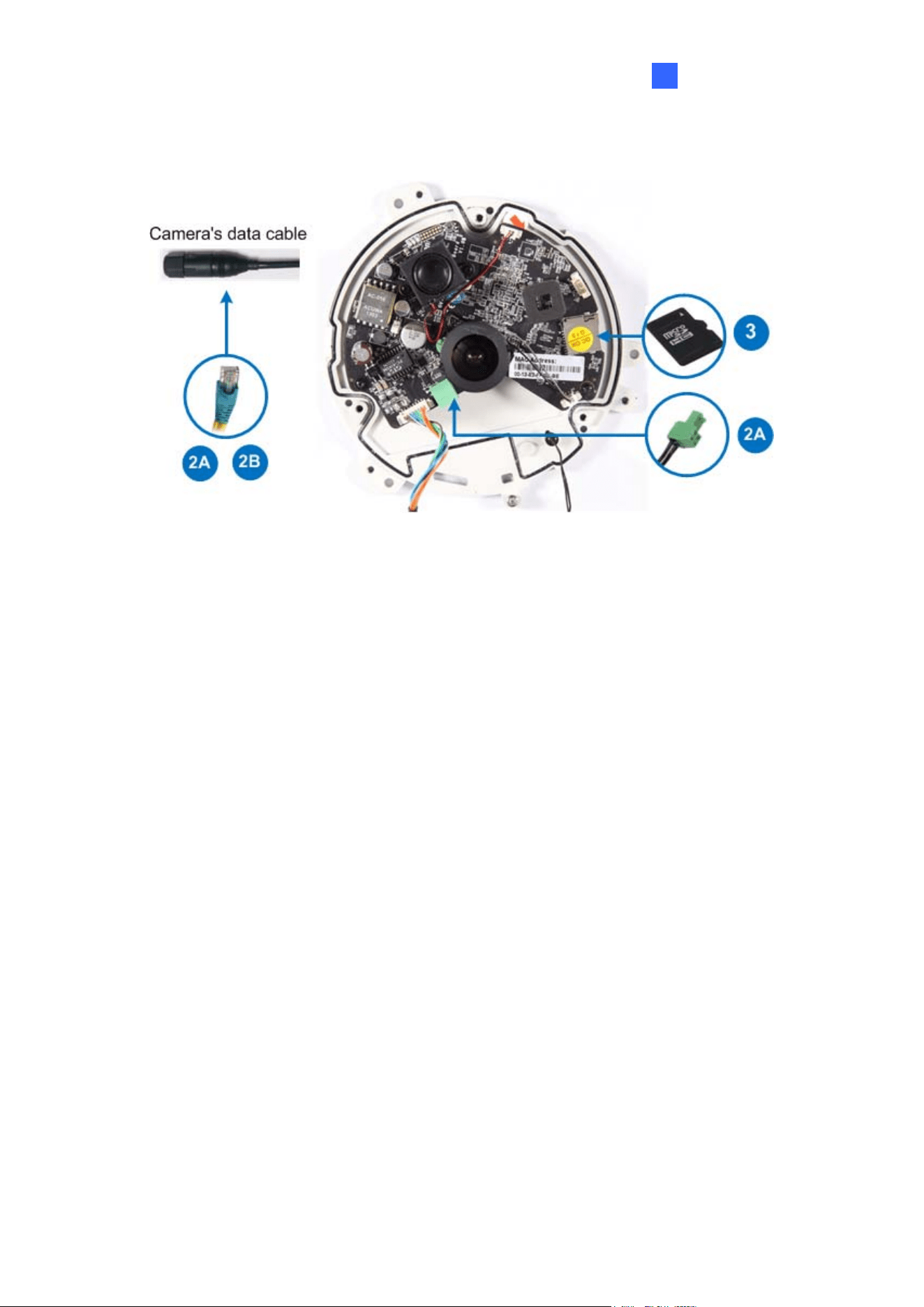
Figure 1-66
1. Remove the camera cover with the supplied torx wrench.
2. Supply power to the camera with one of the following:
A. Power adapter: see Assembling the Power Adapter later in this section.
B. Power over Ethernet (PoE): connect the camera to a PoE switch with a standard
network cable to supply power and network.
3. Optionally insert a micro SD card (SD/SDHC, version 2.0 only, Class 10).
4. Secure the camera cover with the supplied torx wrench.
55
Loading ...
Loading ...
Loading ...