1. SAFETY
IMPORTANT: Always refer to the vehicle manufacturer’s service instructions, or proprietary manual to establish the current procedure and
data. These instructions are provided as a guide only.
9 Ensure all Health and Safety, local authority, and general workshop practice regulations are strictly adhered to when using product.
9 Maintain tools in good and clean condition for best and safest performance. DO NOT use test kit if damaged.
9 Account for all tools and parts being used and do not leave them in, or on the engine after use.
9 Ensure you have read and understood the safety aspects of dealing with the fuel injection system and petrol in general before commencing.
9 Wear approved eye protection. A full range of personal safety equipment is available from your Sealey dealer.
9 Keep yourself, clothing and test equipment away from all moving or hot engine parts.
9 Do not wear jewellery and tie back long hair.
9 Before performing a test with the engine running (unless the manufacturer's manual states otherwise), set the parking brake and place
the gear selector in neutral or park, and block the drive wheels.
9 Exhaust gas contains deadly poisonous gases. The test area must be well ventilated - route the exhaust gas outdoors.
2. INTRODUCTION
Used to establish the working condition of the catalytic converter and silencer by measuring the relative back pressure of the system.
Simply connect into the exhaust system using either of the two oxygen sensor dummy adaptors supplied in the kit. Gauge features a
colour-coded scale for easy diagnosis and reads both pressure and vacuum so can be used on other areas of the vehicle allowing testing
of low pressure fuel systems or engine vacuum. Supplied with gauge hanging chain to allow hands-free operation.
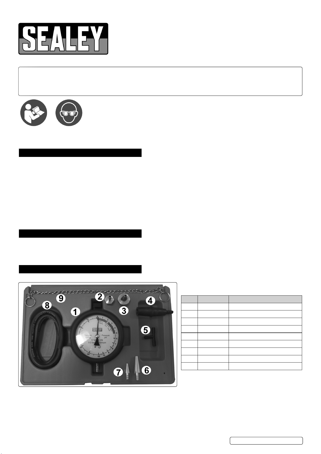
3. CONTENTS
CATALYTIC CONVERTER BACK PRESSURE
TEST KIT
MODEL NO: VSE953
Thank you for purchasing a Sealey product. Manufactured to a high standard, this product will, if used according to these instructions,
and properly maintained, give you years of trouble free performance.
IMPORTANT: PLEASE READ THESE INSTRUCTIONS CAREFULLY. NOTE THE SAFE OPERATIONAL REQUIREMENTS, WARNINGS &
CAUTIONS. USE THE PRODUCT CORRECTLY AND WITH CARE FOR THE PURPOSE FOR WHICH IT IS INTENDED. FAILURE TO DO
SO MAY CAUSE DAMAGE AND/OR PERSONAL INJURY AND WILL INVALIDATE THE WARRANTY. KEEP THESE INSTRUCTIONS SAFE
FOR FUTURE USE.
PART PART NO. DESCRIPTION
1 VSE953.01 Gauge
2 VSE953.06 Oxygen sensor adaptor M12x1.25
3 VSE953.05 Oxygen sensor adapter M18x1.5
4 VSE953.04 Plastic double ended cone
5 VSE953.09 Plastic T piece
6 VSE953.08 Large brass cone adapter
7 VSE953.07 Small brass cone adapter
8 VSE953.03 Hose
9 VSE953.02 Gauge hanging chain
VSE953 Issue 2 (ALL) 16/10/23
Original Language Version
© Jack Sealey Limited
Refer to
instruction
manual
Wear eye
Protection

4. OPERATION
4.1. TESTING THROUGH THE OXYGEN SENSOR PORT
NOTE: See section 3 for part numbers and description of each item.
WARNING! Exhaust systems can get very hot and testing should be carried out when the engine is cold to avoid injury (burns) and so
the rubber hose on the tool does not get too hot and distort. Testing should be completed within 5 minutes of the engine being started
from cold. Allow the engine to cool before removing the Oxygen sensor adaptors because these will be very hot and could cause injury.
NOTE: Before replacing any suspected blocked exhaust components ALWAYS refer to the vehicle manufacturer's specications to
obtain the correct pressure limits.
NOTE: Disconnecting the Oxygen sensor or running the engine with the sensor disconnected may cause the vehicle to illuminate the
MIL (Malfunction Indicator Light) which will require an EOBD diagnostic tool to reset it.
4.1.1. If there are two or more oxygen sensors, start testing at the one nearest the engine and proceed 'downstream'. Disconnect the oxygen
sensor wires and remove the oxygen sensor.
4.1.2. Install the oxygen sensor adaptor (refer to section 3).
4.1.3. Connect the rubber hose and gauge onto the oxygen sensor adaptor.
4.1.4. Start the engine and allow it to idle, the reading should not register over 1psi in the Green scale. If the gauge registers over this
pressure, stop the engine, locate the restriction and correct the fault.
4.1.5. If the idle reading is NOT above 1psi, rev the engine to 2500rpm. The reading should not register over 2.5psi, if the gauge registers over
this pressure, stop the engine, locate the restriction and correct the fault.
4.1.6. If the vehicle has more than one exhaust pipe, with two catalytic converters, each will need to be checked.
4.2. TESTING THE CATALYTIC CONVERTER
4.2.1. If a blocked catalytic converter is suspected, test again after the converter using the second oxygen sensor (post cat) port. If the
converter is blocked the gauge will read a lower pressure than the rst sensor (pre cat) port. For example, if the rst oxygen sensor port
reads 4psi and the second oxygen sensor reads 0.5psi, this shows a blocked catalytic converter.
4.3. TESTING VEHICLES WITHOUT OXYGEN SENSORS
4.3.1. If the vehicle isn't tted with oxygen sensors or they can't be removed it is possible to drill a small hole in the side of the exhaust pipe,
(away from any welds and NOT into the catalyst), and use one of the brass cone adaptors o obtain a reading. After testing the small hole
will require lling with either a small self tapping screw or weld.
4.4. VACUUM TEST
4.4.1. Use the supplied adaptors to connect gauge as close to the inlet manifold as possible, ensure that the hose is not kinked. Should an
engine have two inlet manifolds carry out separate tests on each manifold.
4.4.2. Start engine, if required adjust idle speed to obtain a smooth tick over. If the gauge needle remains steady with a reading between 43
and 55cmHg, the engine is in good condition.
4.4.3. If the gauge drops back about 10cmHg on the dial, this would indicate sticky valves. Disconnect the vacuum hose and spray penetration
oil into the manifold to lubricate the valves.
4.4.4. If the needle consistently drops, this would indicate that the valve clearances are too tight or that a valve has burnt out.
4.4.5. If the needle pulsates rapidly when the rpm is increased, this indicates that valve springs may be weak.
4.4.6. If the needle pulsates rapidly at idle, and steadies out when the rpm is increased, this indicates that the valve guides are worn or loose.
4.4.7. If the needle is slow to drop back after engine rpm has been increased several times in sucession, this would indicate that the exhaust
system may be partially blocked.
4.4.8. If the gauge indicates less than 25cmHg, this would indicate that the valve timing is late.
4.4.9. To check the choke, close the throttle and turn the engine over using the starter motor, the gauge should rise quickly to 55cmHg. If the
gauge remains at a low reading or 7 to 15cmHg then the throttle may not be fully closed or there may be an air leak in the inlet manifold.
NOTE: Gauge readings will vary with altitude, at sea level the vacuum gauge will drop by 2.5cmHg. For instance at 2000ft the reading
will be 44cmHg.
Sealey Group, Kempson Way, Suffolk Business Park, Bury St Edmunds, Suffolk. IP32 7AR
01284 757500 sales@sealey.co.uk www.sealey.co.uk
Note: It is our policy to continually improve products and as such we reserve the right to alter data, specications and component parts without prior notice.
Important: No Liability is accepted for incorrect use of this product.
Warranty: Guarantee is 12 months from purchase date, proof of which is required for any claim.
ENVIRONMENT PROTECTION
Recycle unwanted materials instead of disposing of them as waste. All tools, accessories and packaging should be
sorted, taken to a recycling centre and disposed of in a manner which is compatible with the environment. When
the product becomes completely unserviceable and requires disposal, drain any uids (if applicable) into approved
containers and dispose of the product and uids according to local regulations.
REGISTER YOUR
PURCHASE HERE
VSE953 Issue 2 (ALL) 16/10/23
Original Language Version
© Jack Sealey Limited
