Loading ...
Loading ...
Loading ...
33
AXIS P8221 - Unit connectors
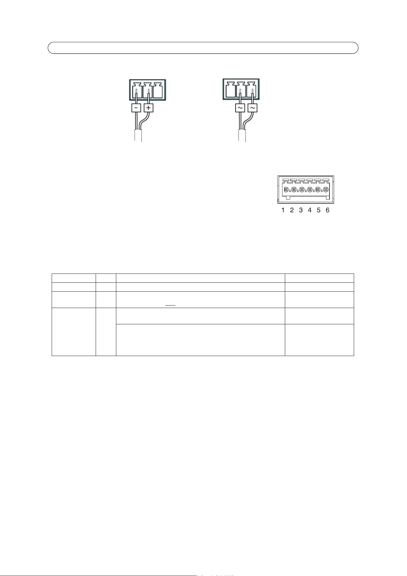
Power connector - 3-pin terminal block used for power input.
I/O terminal connectors A and B - Used in applications for e.g. event triggering and
alarm notifications. In addition to an auxiliary power and a GND pin, each I/O terminal
connector has 4 pins that can be configured as either input or output. These pins provide
the interface to:
• Digital output - For connecting external devices such as relays and LEDs. Connected
devices can be activated by the VAPIX® Application Programming Interface, output
buttons on the Live View page or by an Event Type. The output will show as active (shown under Ports & Devices >
I/O Ports) if the alarm device is activated.
• Digital input - An alarm input for connecting devices that can toggle between an open and closed circuit, for exam-
ple: PIRs, door/window contacts, glass break detectors, etc. When a signal is received the state changes and the input
becomes active (shown under Ports & Devices > I/O Ports, and, if enabled, on the Live View page).
Function Pin Notes Specifications
GND 1 Ground
3.3V DC Power 2 Can be used to power auxiliary equipment.
Note: This pin can only
be used as power out.
Max load = 250mA
Configurable
(Input or
Output)
3-6 Digital input – Connect to GND to activate, or leave floating
(unconnected) to deactivate.
Min. input = -40V DC
Max. input= +40V DC
Digital output – Uses an open-drain NFET transistor with the
source connected to GND. If used with an external relay, a diode
must be connected in parallel with the load, for protection against
voltage transients.
Max. load =100 mA
Max. voltage = + 40V DC
DC power input
8-34 V DC, max 8.2 W
AC power input
20-24 V AC, max 13.7 VA
Loading ...
Loading ...
Loading ...