Loading ...
Loading ...
Loading ...
INSTALLATION
PAGE 9
ENGLISH
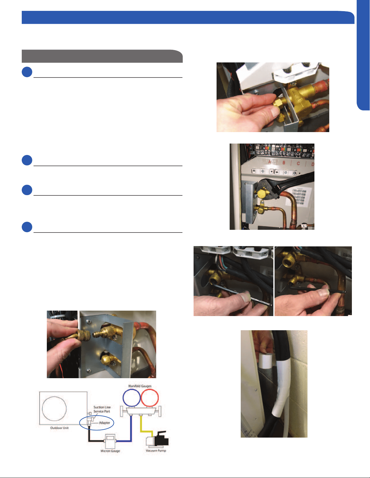
Step 4.3
Step 4.5
Step 4.4A
Step 4.4B
System Evacuation
4.2
Step - 4.2
Attach a manifold gauge, micron gauge, and vacuum pump
(Illustration 5)
Evacuate the system to 350 microns.
Close the vacuum pump valve and check the micron
gauge. If the gauge rises above 500 microns in 60 seconds,
evacuation is incomplete or there is a leak in the system. If
the gauge does not rise above 500 microns in 60 seconds,
evacuation is complete.
4.3
Step - 4.3
Remove the adapter and hose connection from the suction
line port, and replace the cap.
4.4
Step - 4.4A & 4.4B
Remove the caps from the liquid line and suction line valves
valve. Using the hex wrench, open each of the valves, then
replace and tighten the caps.
4.5
Step - 4.5
Wrap the lineset, drain line, and wiring starting at the bottom
of the bundle with an overlap type wrap, concluding at the
piping hole. Use a sealant to seal the piping hole opening to
prevent weather elements from entering the building.
Verify the condensate drain line has a constant pitch
in the failure of the condensate to exit the piping.
Illustration 5
Step 4.2
Step 4 - Leak Test and Evacuation
Note: This system has one set of service valves. When evacuating the system, the service valve ports will have access to all in-
door units and refrigerant line sets. Evacuation at the service valve ports will evacuate the ENTIRE piping system including indoor
units.
Loading ...
Loading ...
Loading ...