Loading ...
Loading ...
Loading ...
INSTALLATION
PAGE 11
ENGLISH
Wiring Error Check
This unit is capable of automatically checking for wiring errors
between the indoor and outdoor units.
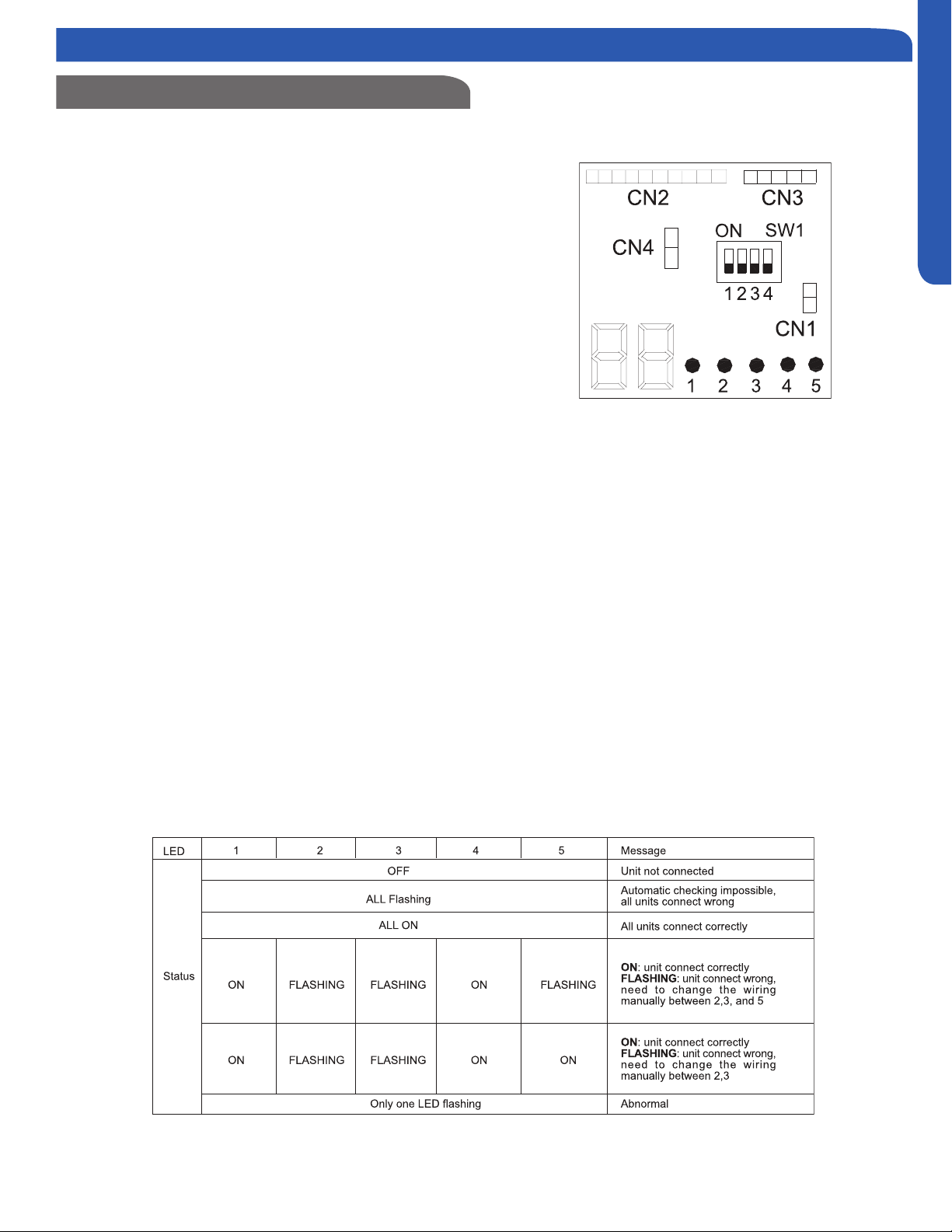
To enter the wiring error check test, place all 4 DIP switches
of the test board to the ON position. (Illustration 6) Remove
and reapply power to the unit, the system will enter the
operation of “Wiring Error Check”.
The numeric display will initialize and begin to alternate
between the compressor working frequency (a number
representing the Hz value) and “CH” (Checking).
As the check is being performed, all units that are properly
connected will be indicated by the corresponding LED for
that circuit being lit constantly. (LED 1 = piping circuit A, LED
2 = piping circuit B, ...)
After the check has completed, if all wiring is correct,
the numeric display will indicate “0” and the single LEDs
representing the individual circuits for the connected indoor
units will be lit constantly.
“EC” (error connection), and th corresponding LED for the
needed.
Refer to the chart shown below. (Table 2)
When the test is complete, remove power to the system and
return the 4 DIP switches to the OFF position. Reapply power
to the the system. The test is complete.
If the self-check is not possible, check the indoor unit wiring
and piping in the usual manner.
Illustration 6
Table 2
Step 5 - Electrical Connections
Loading ...
Loading ...
Loading ...