INSTALLATION
PAGE 1
ENGLISH
Installation Manual
Table of Contents
Outdoor Unit Installation ................................................................................................................. 2-13
Introduction - Overview ....................................................................................................................................2-4
Step 1 - Preparation .............................................................................................................................................. 5
Step 2 - Installation of the Outdoor Unit ............................................................................................................. 6
Step 3 - Refrigerant Line Connections .............................................................................................................6-8
Step 4 - Leak Test and Evacuation ....................................................................................................................8-9
Step 5 - Electrical Connections .................................................................................................................... 10-11
Step 6 - Charging ................................................................................................................................................ 12
Step 7 - System Test .......................................................................................................................................... 12
Step 8 - Explaining Operation to the End User .................................................................................................. 12
Seacoast Application .......................................................................................................................................... 13
Indoor Unit Installation - Cassette ................................................................................................. 14-19
Introduction - Overview ............................................................................................................................... 14-15
Step 1 - Preparation ............................................................................................................................................ 16
Step 2 - Installation of the Cassette Unit .................................................................................................... 17-18
Step 3 - Electrical Connections .......................................................................................................................... 19
Step 4 - Louver Installation ................................................................................................................................ 19
Step 5 - Pull Vacuum on System ......................................................................................................................... 19
Indoor Unit Installation - Wall Mount .............................................................................................. 20-24
Introduction - Overview ..................................................................................................................................... 20
Step 1 - Preparation ............................................................................................................................................ 21
Step 2 - Installation of the Wall Mount Unit ................................................................................................. 22-23
Step 3 - Electrical Connections .......................................................................................................................... 24
Step 4 - Pull Vacuum on System ......................................................................................................................... 24
Indoor Unit Installation - Slim Duct ................................................................................................ 25-30
Introduction - Overview ............................................................................................................................... 25-26
Step 1 - Preparation ............................................................................................................................................ 27
Step 2 - Installation of the Slim Duct Unit ................................................................................................... 28-29
Step 3 - Electrical Connections .......................................................................................................................... 30
Step 4 - Pull Vacuum System .............................................................................................................................. 30
Remote Controller ......................................................................................................................... 31-34
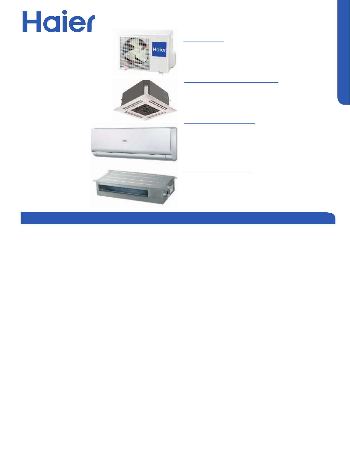
Ductless Split Heat Pump
Outdoor Unit
18K: 2U18MS2VHB
24K: 3U24MS2VHB
36K: 4U36MS2VHB
Compact Cassette Type Indoor
9K: AB09SC2VH*
12K: AB12SC2VH*
18K: AB18SC2VH*
Wall Mount Type Indoor
7K: AW07LC2VH*
9K: AW09LC2VH*
12K: AW12LC2VH*
18K: AW18LC2VH*
Slim Duct Type Indoor
7K: AD07SL2VH*
9K: AD09SL2VH*
12K: AD12SL2VH*
18K: AD18SL2VH*
INSTALLATION
PAGE 2
ENGLISH
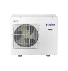
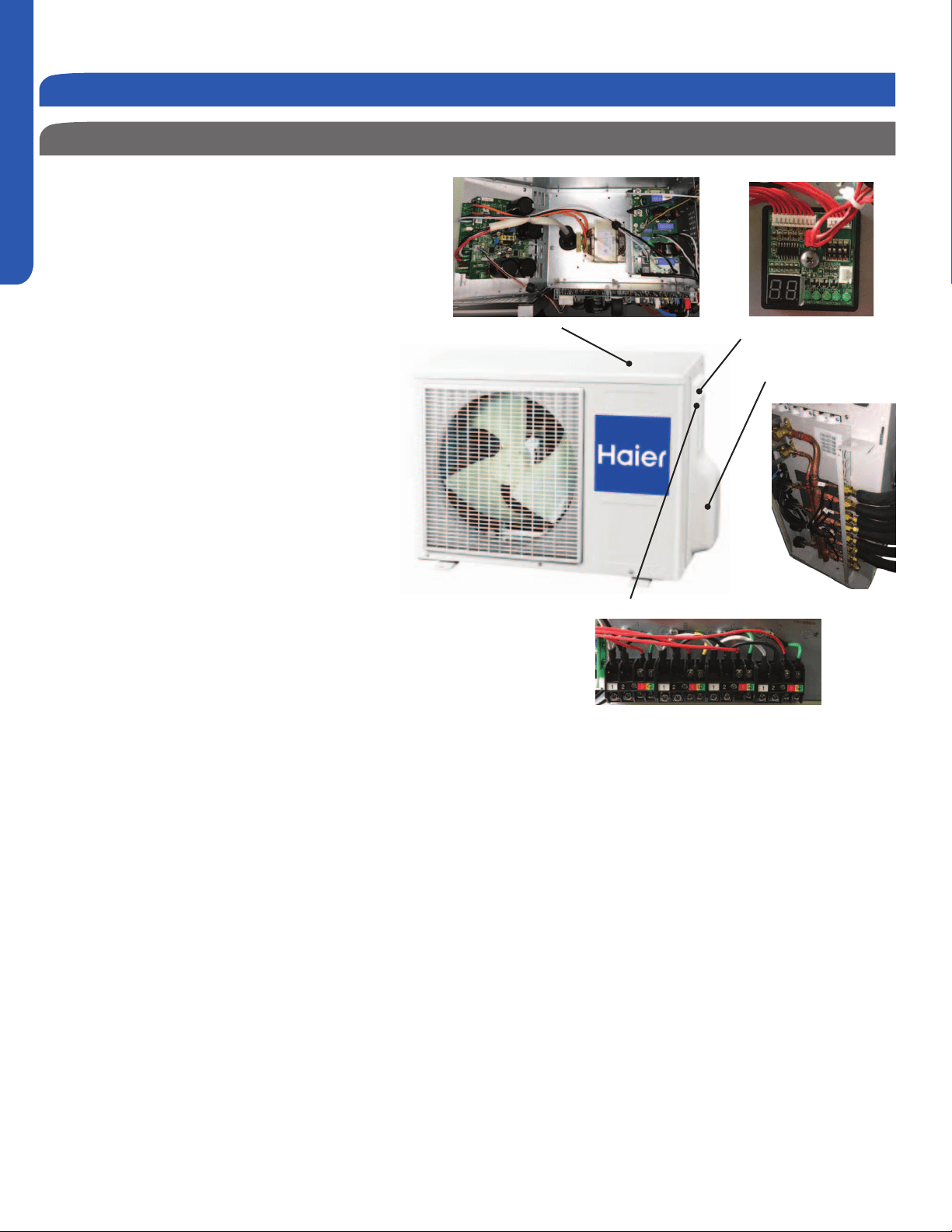
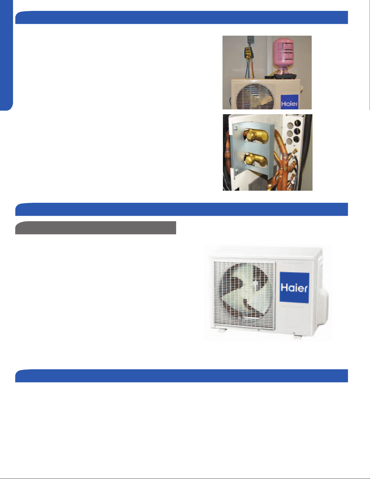
Outdoor Unit Product Information
The FlexFit Multi-zone Heat Pump systems feature DC
The inverter technology operates variable speed
compressors and fan motors. The outdoor is equipped
with electronic expansion valves , which control
is installed. All of the outdoor units feature an internal
oil separator to increase compressor live. These
systems use R-410A refrigerant.
Some models feature self diagnostic boards that will
system start up.
All outdoor units have built in diagnostic error
detection circuits. If an error is detected, the
system will take the necessary steps to either make
adjustments or shut down to prevent damage from
occuring. Some error codes will be displayed on the
indoor unit display panel.
These systems can be connected to up to 4 individual
indoor units. It is not necessary to use all of the
available ports. The available combinations of indoor
and outdoor unit capacities are listed in this manual.
Available indoor units include high wall type, cassette
type and Slim Duct/Concealed type.
The outdoor unit provides power to indoor units via
terminal connections on the outdoor unit.
Flare Connections
and Ports
Self Diagnostic Board
Indoor Unit Power and Comm Wiring
Control Boards
Outdoor Unit Installation
Introduction - Overview
INSTALLATION
PAGE 3
ENGLISH
Introduction - Overview
Outdoor Unit Product Information
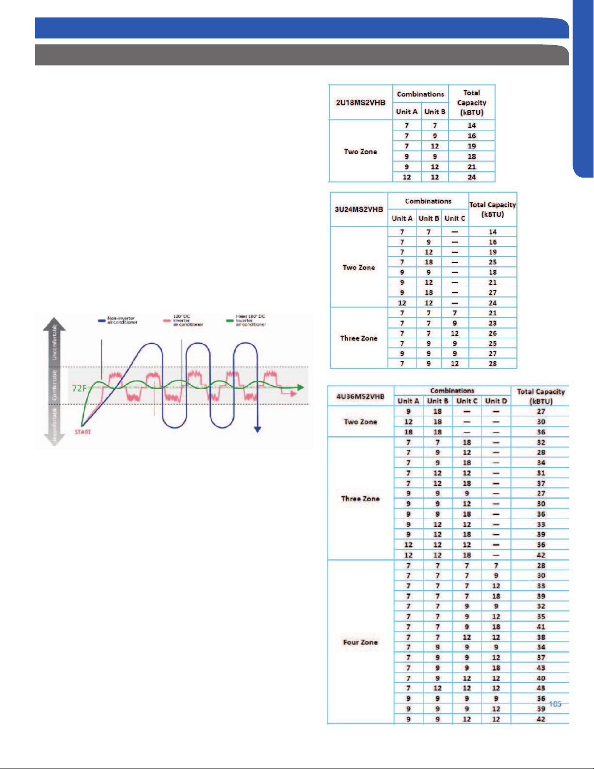
Temperature Control and the Inverter
The outdoor unit inverter will operate the compressor,
outdoor fan motor and indoor fan motor at the proper speed
to provide enough capacity to satisfy the heat load from all
operating indoor units.
As the temperature in the zones gets closer to the setpoint
requirement, the inverter will slow everything down. This is
normal operation.
As temperature setpoint is reached, the inverter will run
everything slowly to provide small amounts of capacity to
keep the rooms comfortable. At times, the air coming out of
the indoor units will be close to or at room temperature. This
is normal.
This precise match of capacity and load is how ductless air
Matching up the outdoor unit to indoor units
The approved combinations of indoor unit capacity and
outdoor unit model are shown at the right. The capacity
ratings can be matched to any of the high wall, cassette, or
Slim Duct/Concealed models.
The systems are not rated for use of only 1 indoor unit. Do
not vary from the available combinations in these tables.
When ports are not used, always connect the refrigerant
lines to circuits located at the outdoor units lowest possible
outdoor port size to the required port size of the indoor unit.
Operating Temperature Ranges
• Cool Mode: 14
O
F - 114
O
F
• Heat Mode: 5
O
F - 74
O
F
INSTALLATION
PAGE 4
ENGLISH
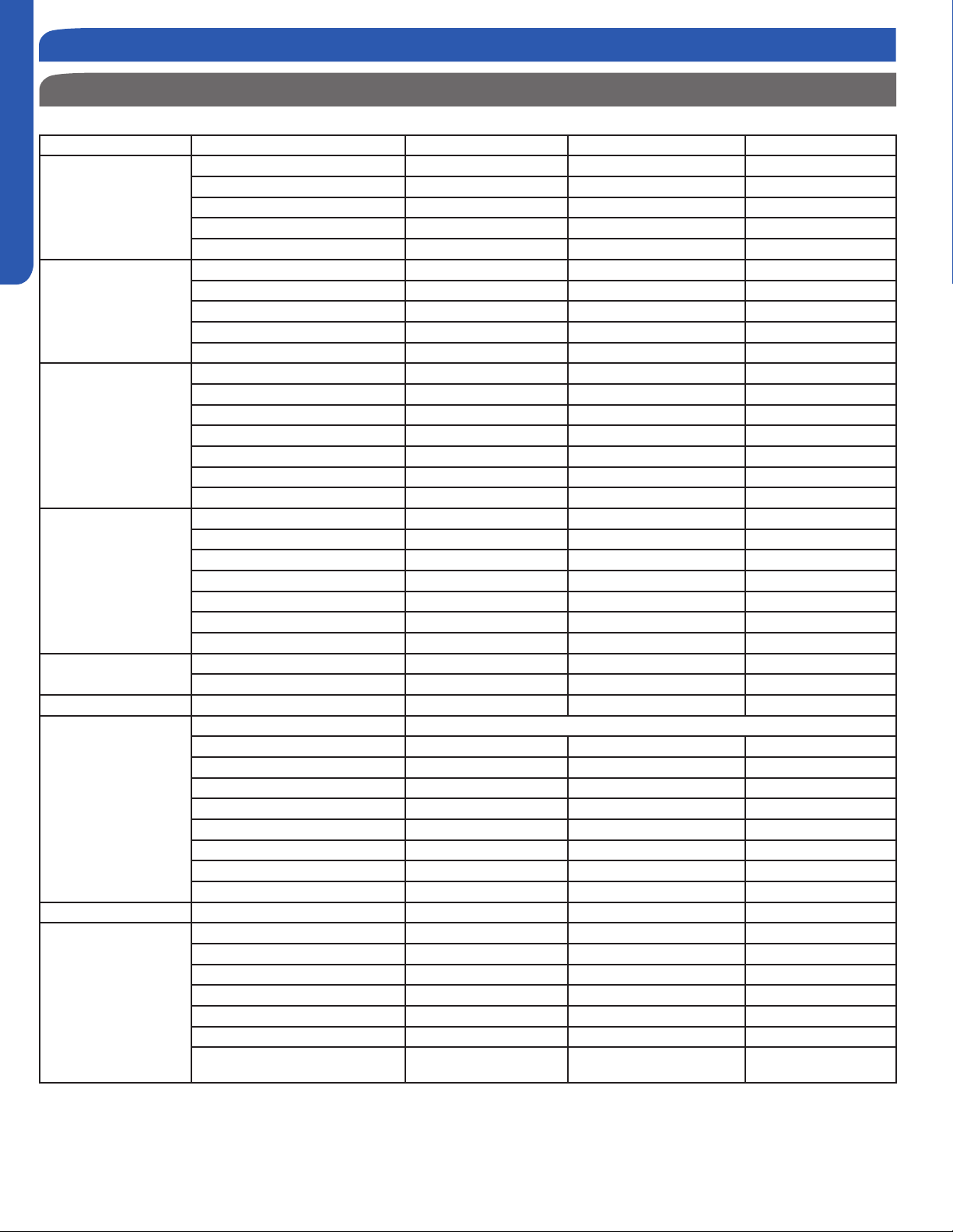
Product Specications
Model Number Outdoor 2U18MS2VHB 3U24MS2VHB 4U36MS2VHB
Cooling Non-ducted
Rated Capacity Btu/hr 17,400 22,500 34,000
Capacity Range Btu/hr 4,400-19,400 5,000-24,500 5,000-36,000
Rated Power Input W 1,650 2,250 3,770
SEER 16.0 18.0 18.0
EER 10.5 10.0 9.0
Cooling Ducted
Rated Capacity Btu/hr 16,500 21,000 31,000
Capacity Range Btu/hr 4,400-19,400 5,000-23,000 5,000-34,000
Rated Power Input W 1,800 2,416 3,590
SEER 15.5 16.0 16.0
EER 8.5 8.5 8.5
Heating Non-ducted
Rated Heating Capacity 47°F Btu/hr 19,100 23,000 34,500
Heating Capacity Range Btu/hr 6,100-22,100 6,100-25,500 6,100-36,500
Rated Power Input W 1,570 1,700 2,650
HSPF
9.0 10.0
10.0
Rated Heating Capacity 17°F Btu/hr 13,000 15,000 22,000
Max. Heating Capacity 17°F Btu/hr 14,000 18,000 26,000
Max. Heating Capacity 5°F Btu/hr 12,000 16,000 24,000
Heating Ducted
Rated Heating Capacity 47°F Btu/hr 18,000 22,000 33,000
Heating Capacity Range Btu/hr 6,100-22,100 6,100-25,000 6,100-35,000
Rated Power Input W 1,700 2,100 3,000
HSPF 8.2 8.5 9.0
Rated Heating Capacity 17°F Btu/hr 10,000 14,000 21,000
Max. Heating Capacity 17°F Btu/hr 12,000 17,000 25,000
Max. Heating Capacity 5°F Btu/hr 10,000 15,000 23,000
Operating Range
Cooling °F(°C) 14~115(-10~46) 14~115(-10~46) 14~115(-10~46)
Heating °F(°C)
-4~75(-20~24) -4~75(-20~24) -4~75(-20~24)
Power Supply Voltage, Cycle, Phase V/Hz/- 208-230/60/1 208-230/60/1 208-230/60/1
Outdoor Unit
Compressor Type DC Interver Driven Rotary
Maximum Fuse Size A 25 25 30
Minimum Circuit Amp A 15 18 23
Outdoor Fan Speed RPM 300 ~ 900 300 ~ 900 300 ~ 900
Outdoor Noise Level dB 53 54 56
Dimension: Height in (mm) 27 1/16(688) 28 3/4(730) 33 1/16(840)
Dimension: Width in (mm) 31 7/8(810) 33 7/8(860) 37 5/16(948)
Dimension: Depth in (mm) 11 5/16(288) 12 1/8(308) 13 3/8(340)
Weight (Ship/Net)- lbs (kg) 102.5/95.9(46.5/43.5) 123.4/116.8(56/53) 191.8/167.5(87/76)
Indoor Unit Max Indoor units 2 3 4
Refrigerate Line
Connections Flare Flare Flare
Liquid O.D. in 1/4 1/4 1/4 1/4 1/4 1/4 1/4 1/4 1/4
Suction O.D. in 3/8 3/8 3/8 3/8 3/8 3/8 3/8 3/8 1/2
Factory Charge Oz 49.5 74.0 113.0
Maximum Line Length Ft / m 100/30 200/60 230/70
Maximum Height Ft / m 50/15 50/15 50/15
Maximum Line Length for each indi-
vidual indoor unit Ft / m
82/25 82/25 82/25
Introduction - Overview
INSTALLATION
PAGE 5
ENGLISH
Outdoor Unit Clearances
Step 1 - Preparation
more than 8 in.
more than 6 in.
more than 4 in.
more than 4 in.
more than 24 in.
more than 10 in.
Required Tools for Installation Procedure for Selecting the Location
Drill
Wire Snipper
Hole Saw 2 3/4”
Vacuum pump
Soap-and-water solution or gas leakage
detector
Torque wrench
17mm, 22mm, 26mm
Tubing cutter
Flaring tool
Razor knife
Measuring tape
Level
Micron gauge
Nitrogen
Mini-Split AD-87 Adapter (1/4” to 5/16”)
A - Non-adhesive Tape
B - Adhesive Tape
C - Saddle (L.S.) with screws
D - Electrical wiring
E - Drain hose (Included)
F - Insulation
G - Piping hole cover (Included)
more than 10ft away depending on radio
wave conditions.)
do not place anything under the unit that
must be kept away from moisture.
Note:
1) Cannot be installed hanging from ceiling
or stacked.
2) If installing on a high place such as a roof,
with a fence or guard rail around it.
3) If there is a potential for accumulated
snow to block the air inlet or heat ex-
changer, install the unit on a higher base.
4) R-410A refrigerant is a safe, nontoxic and
there is a concern about a dangerous level
of refrigerant concentration in the case of
refrigerant leakage, add extra ventilation.
5) Avoid installing the outdoor unit where
corrosive gases, such as sulfur oxides, am-
monia, and sulfurous gas, are produced. If
unavoidable, consult with an installation
specialist about using a corrosion-proof or
anti-rust additive to protect the unit coils.
Choose a place solid enough to bear
the weight and vibration of the unit and
where the operation noise will not be
Choose a location where the hot air
discharged from the unit or the operation
noise and will not cause a nuisance to the
neighbors of the user.
carrying the unit into and out of the site.
passage and no obstructions around the
air inlet and air outlet.
The site must be free from the possibility
place.
Locate the unit to avoid noise and
discharged hot air will not annoy the
neighbors.
Install units, power cords and inter-unit
cables at least 10ft away from television
and radio sets. This is to prevent
interference to images and sounds.
(Noise may be heard even if they are
INSTALLATION
PAGE 6
ENGLISH
Set the Outdoor Unit
2.1
Step - 2.1
Set the unit on mount or pad. If located in snow area, use heat
pump risers to elevate the outdoor unit.
Make sure the outdoor unit is installed level and is stable.
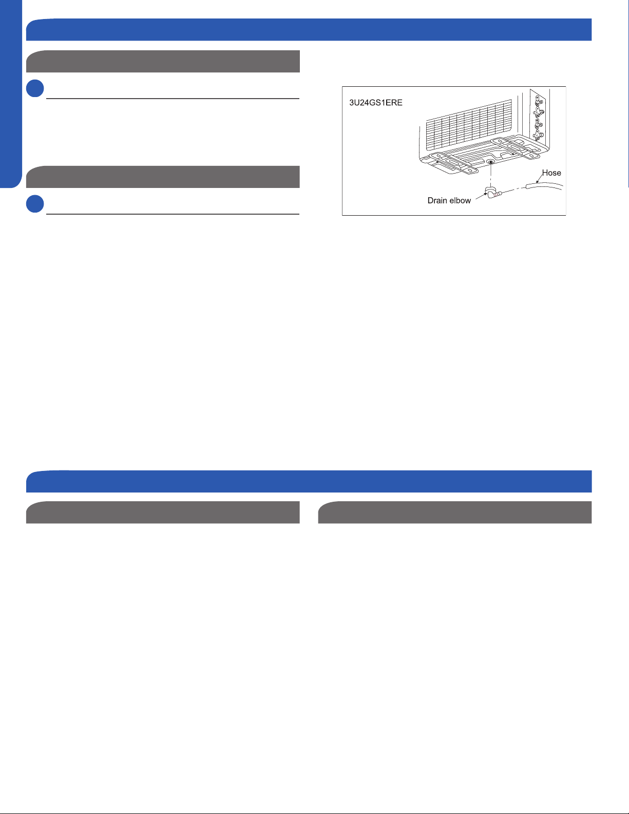
Step 2.2
Attaching Drain Elbow to Outdoor Unit
2.2
Step - 2.2
If the unit is located in an area where freezing can occur, do
these instructions.
If attaching the supplied drain elbow to the outdoor unit,
do so prior to attaching the refrigerant lines and wiring.
Use drain plug for drainage.
surface, place additional foot bases of at least 1 1/6 in. in
height under the outdoor unit’s feet.
In cold areas, do not use a drain hose with the outdoor
unit. (Otherwise, drain water may freeze, impairing heating
performance.)
The maximum lift allowed between the outdoor unit and
COMBINED indoor units is 50 feet total of all installed units.
For example, 3 units with 15 elevation each is 45 feet.
The maximum allowable piping length for ALL INSTALLED
indoor units is a total of:
18K Outdoor Models: 100 Feet
24K Outdoor Models: 200 Feet
36K Outdoor Models: 230 Feet
The maximum refrigerant piping length allowable to a
Cassette unit is 82 feet.
Piping Limits Pipe Size
Use the refrigerant line size that is indicated in the
adapters to adapt size to the outdoor unit if necessary.
Step 2 - Installation of the Outdoor Unit
Step 3 - Refrigerant Line Connections
INSTALLATION
PAGE 7
ENGLISH
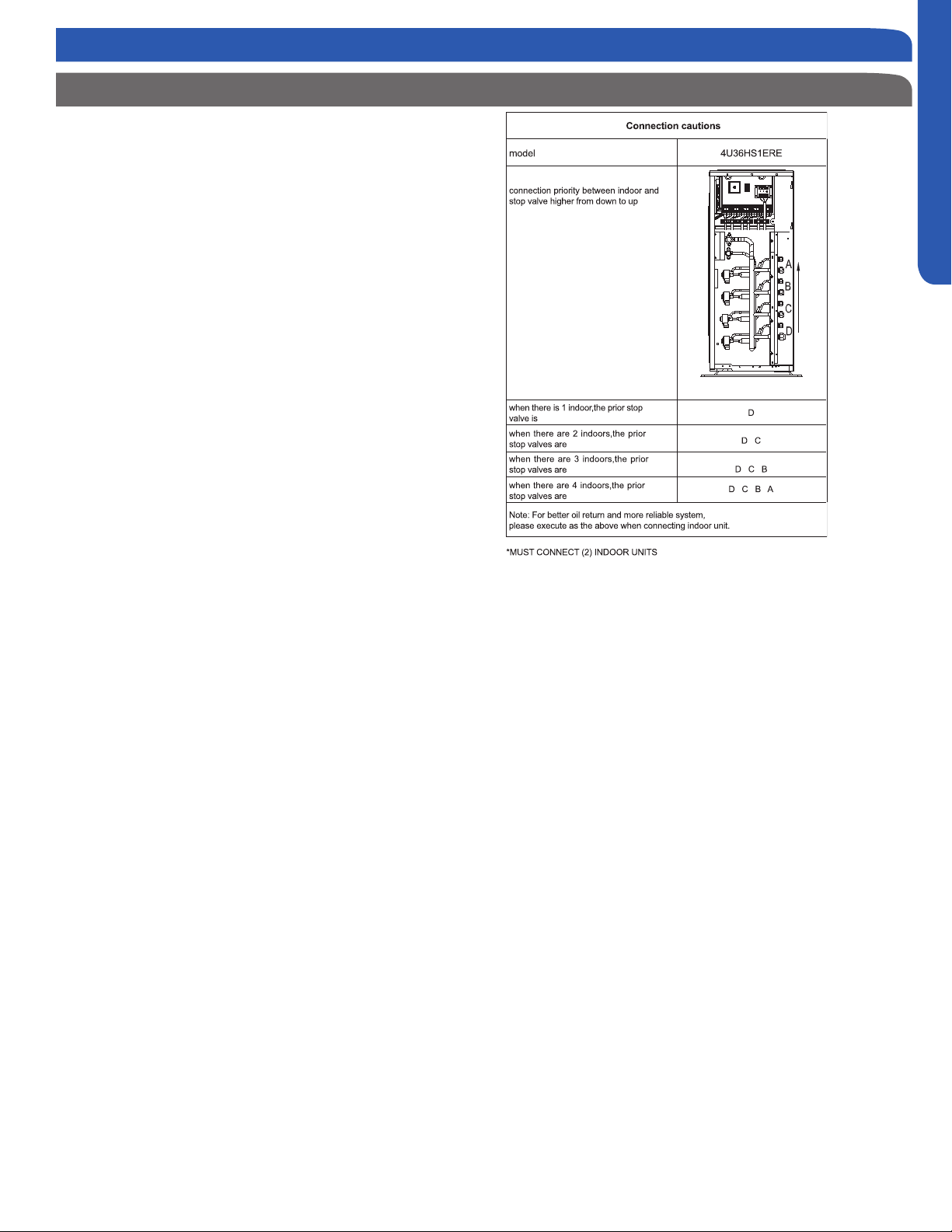
Connection Priority
The line sets are connected to the indoor
piping port connections labeled A through
the unit.
Note: Start the connections at the lowest
port. Always size the lines to the require-
ment of the indoor unit. Use a line size
the port size on the outdoor unit.
If any ports are not used, they remain
capped. Unused ports should be near the
top of the outdoor unit connection mani-
fold. Remember, always start from bottom
to top.
Step 3 - Refrigerant Line Connections
INSTALLATION
PAGE 8
ENGLISH
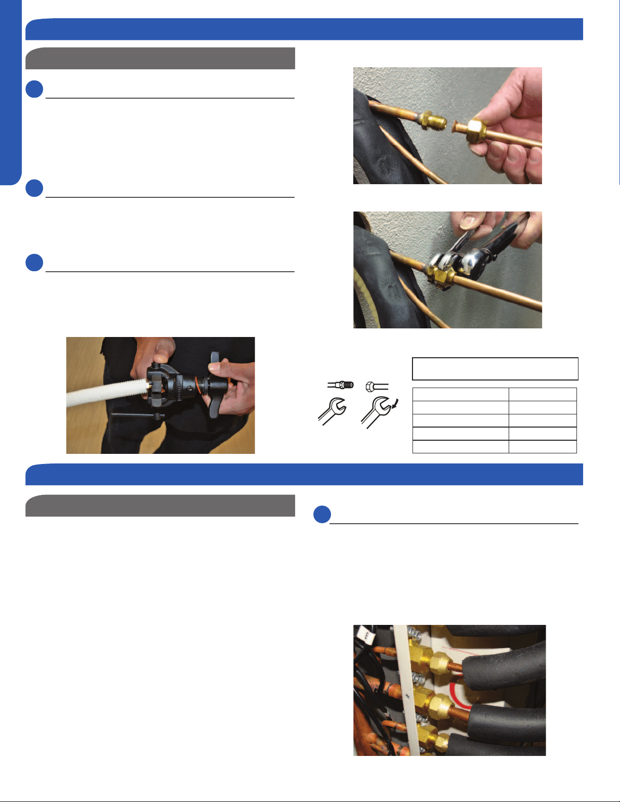
Leak Test
3.1
Step - 3.1
Refrigerant piping connections for the mini-split system are
use caution to prevent dirt or debris from entering the tubing.
Remember to place the nut on the pipe before creating the
3.2
Step - 3.2
To join the lineset piping together, directly align the piping
connection.
3.3
Step - 3.3
standard wrench, and one torque wrench. See Table 1 for the
Step 3.1
Half union
Flarenut
Torque wrench
Spanner
Forced fasteningwithout carefulcentering may
damagethe threads and cause a leakageofgas.
Pipe Diameter(ǿ)Fastening torque
Liquid side6.35mm(1/4") 18N.m/13.3Ft.lbs
Liquid/Gas side9.52mm(3/8") 42 N.m/30.1Ft.lbs
Gasside12.7mm(1/2") 55N.m/40.6Ft.lbs
Gasside15.88mm(5/8") 60 N.m/44.3Ft.lbs
Table 1
Step 3.2
Step 3.3
Hazard of Explosion! Never use an open ame to detect
gas leaks. Explosive conditions may occur. Use a leak test
solution or other approved methods for leak testing. Failure
to follow recommended safe leak test procedures could
result In death or serious injury or equipment or property
damage.
Use only dry nitrogen with a pressure regulator for
pressurizing unit. Do not use acetylene, oxygen or
compressed air or mixtures containing them for pressure
testing. Do not use mixtures of a hydrogen containing
refrigerant and air above atmospheric pressure for pressure
an explosion. Refrigerant, when used as a trace gas should
only be mixed with dry nitrogen for pressurizing units. Failure
to follow these recommendations could result in death or
serious injury or equipment or property damage.
Step 4.1
Piping Connection
Step 3 - Refrigerant Line Connections
Step 4 - Leak Test and Evacuation
4.1
Step - 4.1
Using a tank of nitrogen with attached regulator, charge
the system with 150 PSIG of dry nitrogen. Use adapter AD-
methods. If a leak is detected, repair and recheck. If no leaks
are detected, proceed to evacuate the system.
INSTALLATION
PAGE 9
ENGLISH
Step 4.3
Step 4.5
Step 4.4A
Step 4.4B
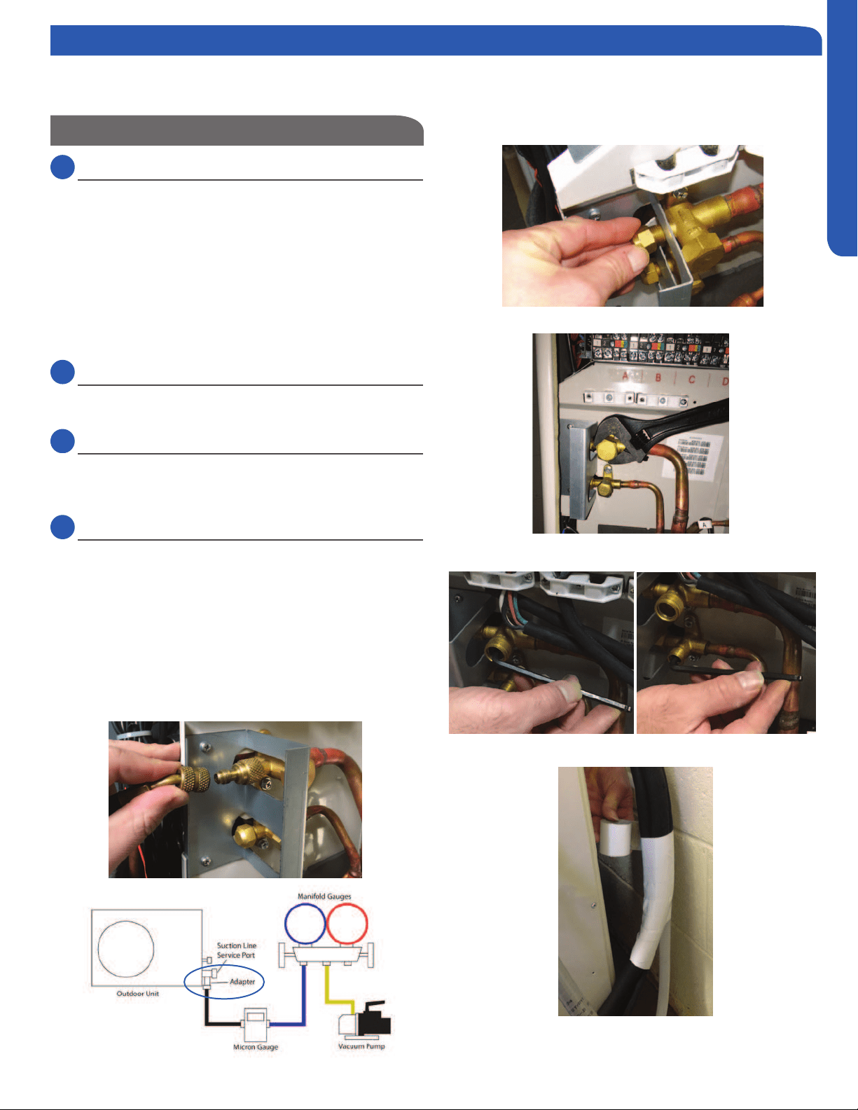
System Evacuation
4.2
Step - 4.2
Attach a manifold gauge, micron gauge, and vacuum pump
(Illustration 5)
Evacuate the system to 350 microns.
Close the vacuum pump valve and check the micron
gauge. If the gauge rises above 500 microns in 60 seconds,
evacuation is incomplete or there is a leak in the system. If
the gauge does not rise above 500 microns in 60 seconds,
evacuation is complete.
4.3
Step - 4.3
Remove the adapter and hose connection from the suction
line port, and replace the cap.
4.4
Step - 4.4A & 4.4B
Remove the caps from the liquid line and suction line valves
valve. Using the hex wrench, open each of the valves, then
replace and tighten the caps.
4.5
Step - 4.5
Wrap the lineset, drain line, and wiring starting at the bottom
of the bundle with an overlap type wrap, concluding at the
piping hole. Use a sealant to seal the piping hole opening to
prevent weather elements from entering the building.
Verify the condensate drain line has a constant pitch
in the failure of the condensate to exit the piping.
Illustration 5
Step 4.2
Step 4 - Leak Test and Evacuation
Note: This system has one set of service valves. When evacuating the system, the service valve ports will have access to all in-
door units and refrigerant line sets. Evacuation at the service valve ports will evacuate the ENTIRE piping system including indoor
units.
INSTALLATION
PAGE 10
ENGLISH
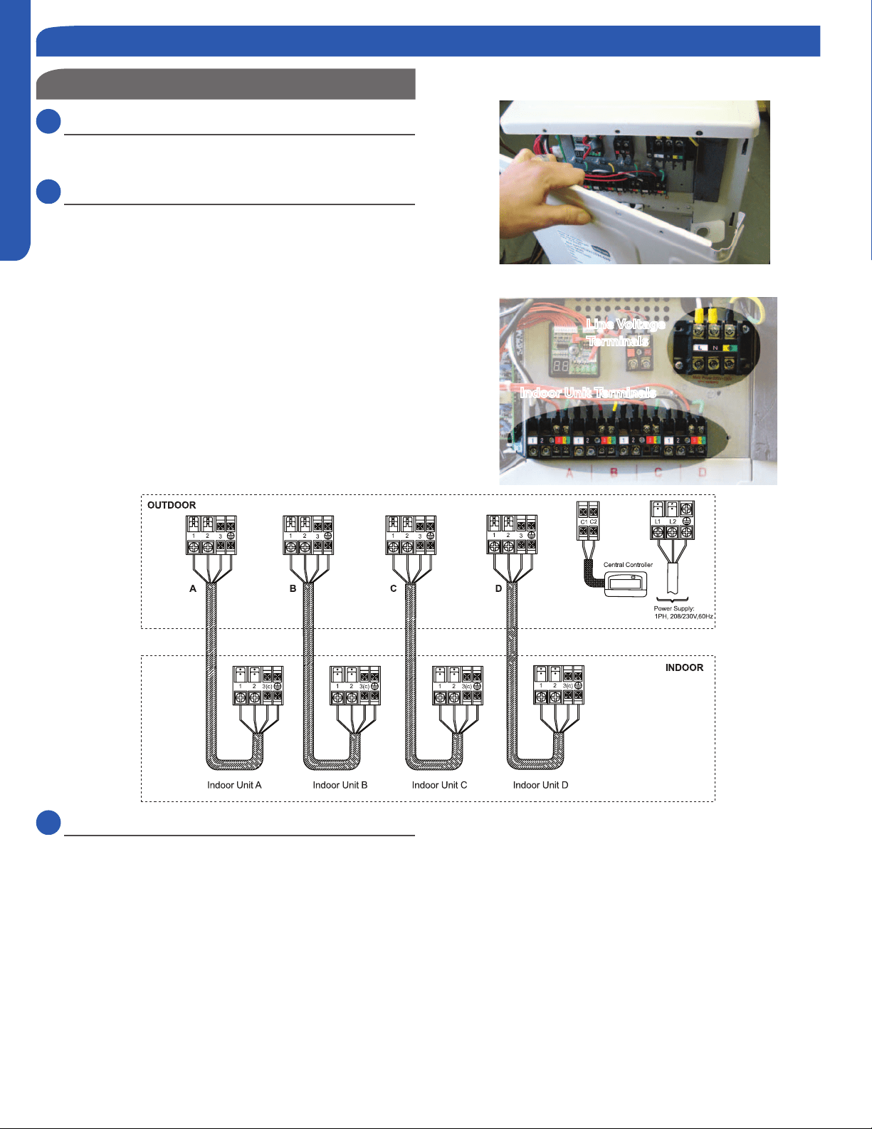
Wiring Unit
5.1
Step - 5.1
Remove the cover plate of the outdoor unit to expose the
terminal block connections.
5.2
Step -5.2
Connect Line Voltage from Circuit Breaker/Disconnect to
outdoor unit wire terminal
Always follow local and national codes when installing
electrical wiring. The required fuse size can be found in the
Connect wiring from indoor units
Use14/4 AWG Stranded wire when connecting the outdoor
unit to the indoor unit. Connect the wiring to the correct
terminals based upon the piping connections. For example,
Circuit A wiring goes to the piping feeding Circuit A. Do not
cross the wiring and piping.
Step 5 - Electrical Connections
5.3
Step - 5.3
Replace the cover plate.
Step 5.1
Step 5.2
Line Voltage
Terminals
Indoor Unit Terminals
INSTALLATION
PAGE 11
ENGLISH
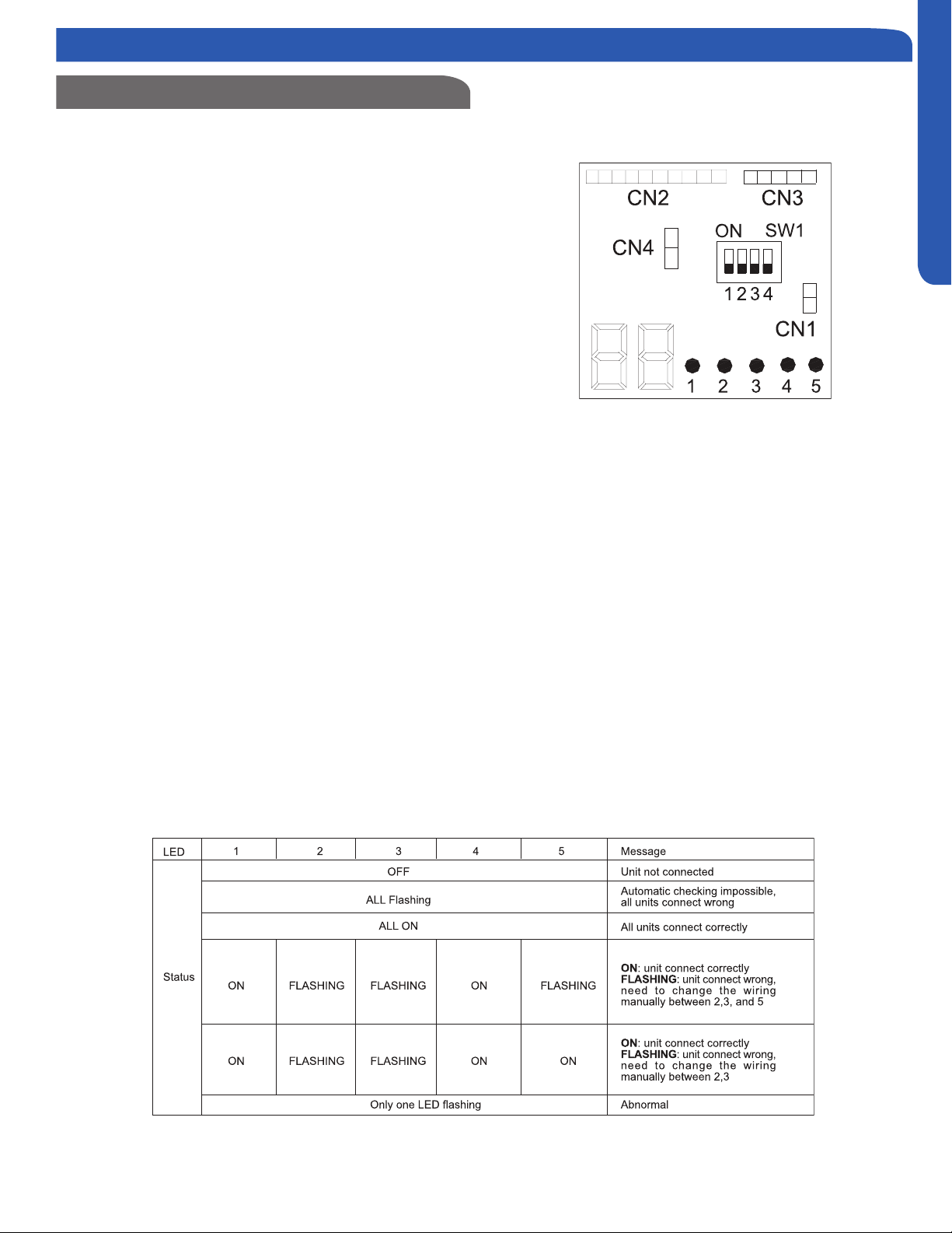
Wiring Error Check
This unit is capable of automatically checking for wiring errors
between the indoor and outdoor units.
To enter the wiring error check test, place all 4 DIP switches
of the test board to the ON position. (Illustration 6) Remove
and reapply power to the unit, the system will enter the
operation of “Wiring Error Check”.
The numeric display will initialize and begin to alternate
between the compressor working frequency (a number
representing the Hz value) and “CH” (Checking).
As the check is being performed, all units that are properly
connected will be indicated by the corresponding LED for
that circuit being lit constantly. (LED 1 = piping circuit A, LED
2 = piping circuit B, ...)
After the check has completed, if all wiring is correct,
the numeric display will indicate “0” and the single LEDs
representing the individual circuits for the connected indoor
units will be lit constantly.
“EC” (error connection), and th corresponding LED for the
needed.
Refer to the chart shown below. (Table 2)
When the test is complete, remove power to the system and
return the 4 DIP switches to the OFF position. Reapply power
to the the system. The test is complete.
If the self-check is not possible, check the indoor unit wiring
and piping in the usual manner.
Illustration 6
Table 2
Step 5 - Electrical Connections
INSTALLATION
PAGE 12
ENGLISH
Check Items for Test Run
Put check mark in boxes
No gas leak from linesets?
Are the linesets insulated properly?
inserted to the terminal block?
Is condensate draining correctly?
Is the ground wire secure? Is the indoor unit secured?
Is power source voltage correct according to local code?
Is there any noise?
Is the lamp normally lighting?
Are cooling and heating performing normally?
Is the operation of room temperature sensor normal?
Step 6 - Charging
Step 7 - System Test
Using the OPERATING INSTRUCTIONS, explain to the user how to use the air conditioner (the remote controller, removing
operation, etc.)
Recommend that the user read the OPERATING INSTRUCTIONS carefully.
Step 8 - Explaining Operation to the End User
Charge the system using the weight method.
The unit comes with enough charge for 25 feet per circuit.
For example, the 2 port unit will come with 50 feet of charge,
the 3 port unit will come with 75 feet of charge, and the 4
port unit will come with 100 feet of charge. If the system
must have additional charge added, add .2 ounces of charge
for every additional foot of refrigerant line that is above
factory charge. If the total of distance of the installed line
Simply release the charge by opening the system service
valves.
INSTALLATION
PAGE 13
ENGLISH
Seacoast Application
Outdoor Unit Installation Complete
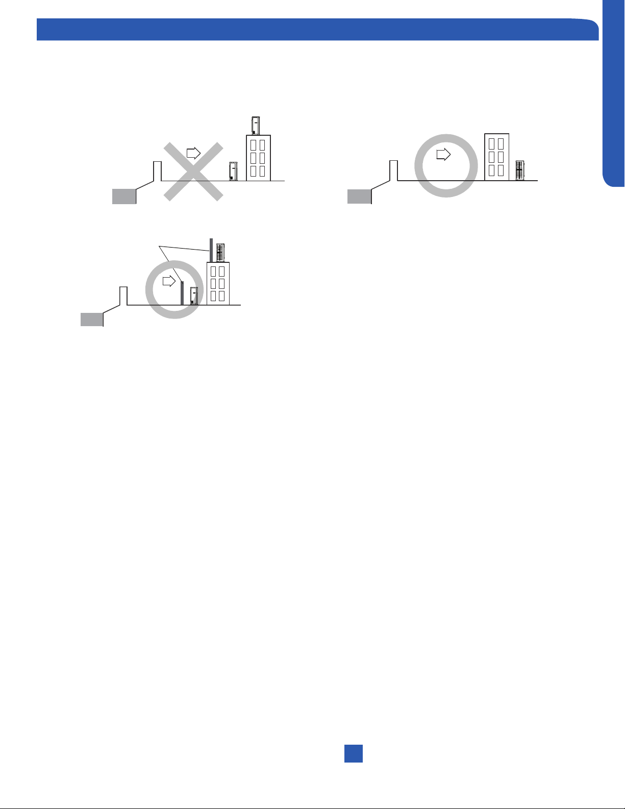
The outdoor unit should be installed at least ½ mile away from the salt water, including seacoasts and inland waterways. If
the unit installed from ½ mile to 5 miles away from the salt water, including seacoasts and inland waterways, please follow the
installation instruction below.
ODU
ODU
Sea breeze
Sea
ODU
Sea breeze
Sea
ODU
Sea breeze
Sea
Protecti on walls
ODU
Install the outdoor unit in a place (such as near buildings etc.) where it can be protected from sea breeze which can damage
the outdoor unit.
If you cannot avoid installing the outdoor unit by the seashore, construct a protection wall around it to block the sea breeze.
A protection wall should be constructed with a solid material such as
concrete to block the sea breeze and the height and the width of the wall
should be 1.5 times larger than the size of the outdoor unit. Also, secure
over 28 in (700mm) between the protection wall and the outdoor unit for
exhausted air to ventilate.
Install the outdoor unit in a place where water can drain smoothly.
dust on the outdoor unit heat exchanger.
INSTALLATION
PAGE 14
ENGLISH
Cassette Indoor Unit Specications
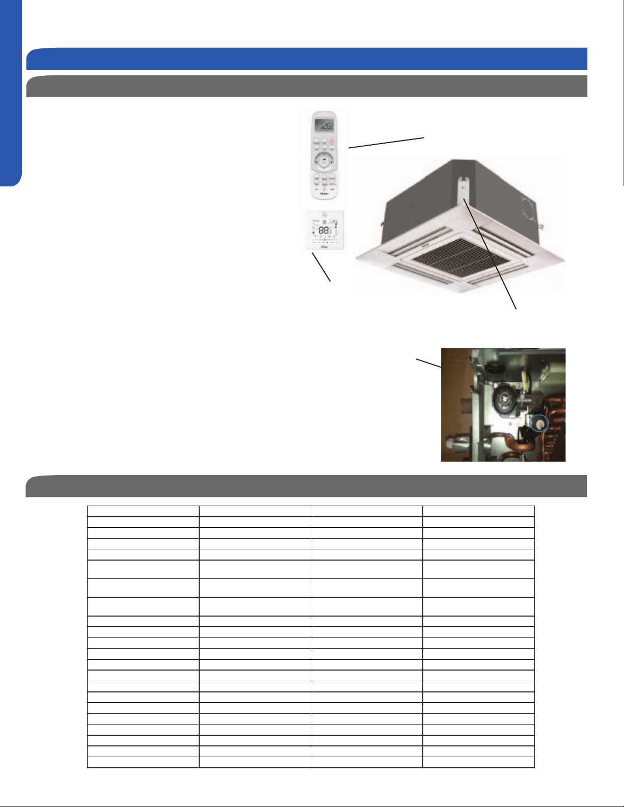
Cassette Product Information
The Cassette Indoor Air Handler ships consists of a cassette
assembly and operational louver. The Cassette Indoor Unit
is operated via a factory supplied remote control. Wired
controller is optional.
The Cassette unit will install between standard dropped
brackets that are located at all four corners of the cassette
assembly.
The Cassette unit receives 230 volt line voltage from a
connection at the outdoor condensing unit. There is no
requirement for independent line voltage connections.
The cassette unit has a built in condensate pump and
Cassette unit. This hose connects the cassette condensate
drain outlet to the buildings condensate drain system.
The motorized louver is controlled via the remote control.
The louver has indicator lights that communicate function
and diagnostic information to the user and service technician.
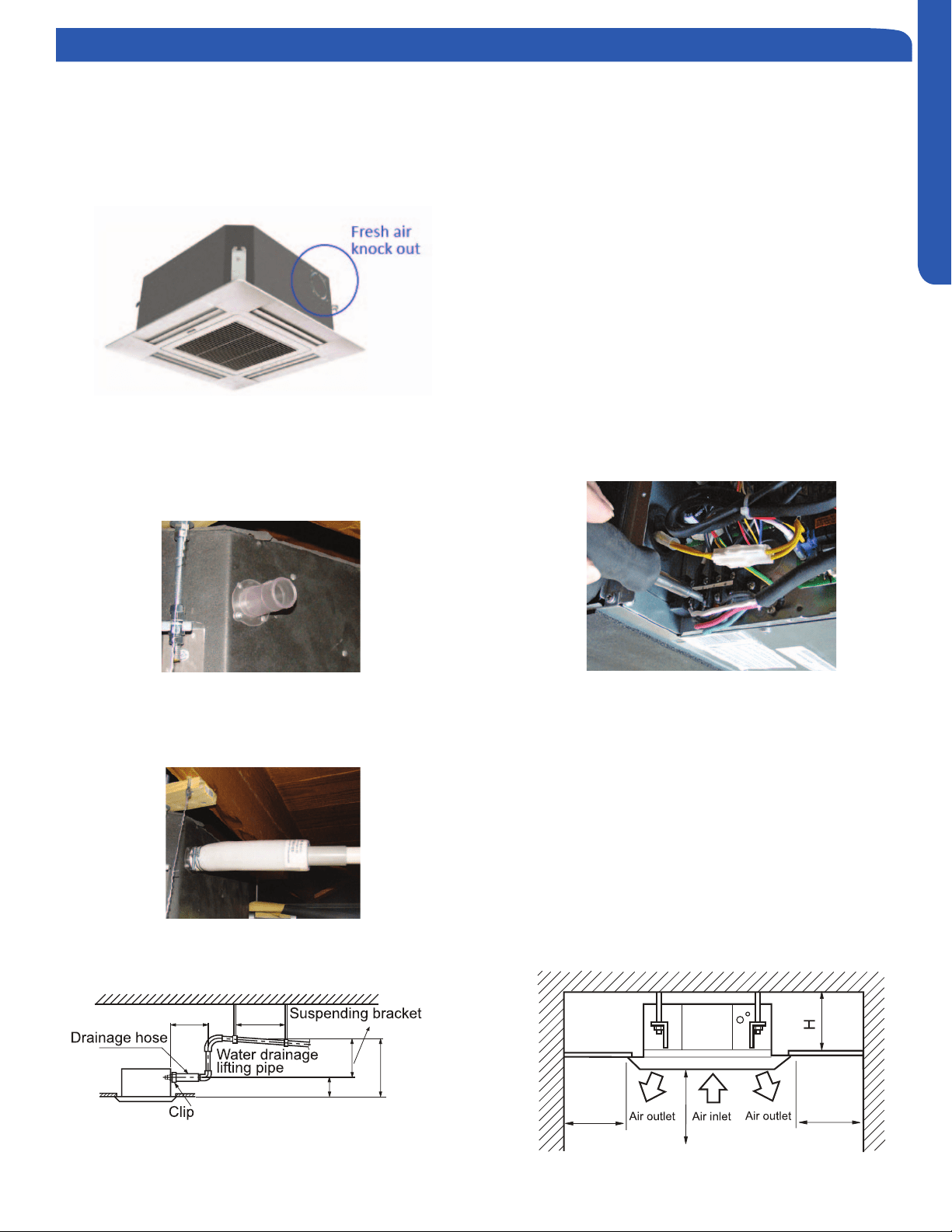
Optional fresh air can be piped into the cassette assembly.
The knockout is located on the side of the cassette assembly.
entering the cassette. A 4” galvanized pipe should be used to
pipe in the fresh air.
Included with the cassette unit is factory provided insulating
tape. This tape should be placed over the refrigerant piping
connections at the indoor unit to prevent sweating.
Built-in Condensate
Pump and Float Switch
Factory Supplied
Remote
Wired Controller is
Optional
Outside Air
Mounting Hangers
Indoor Unit Installation - Cassette
Indoor AB09SC2VHA AB12SC2VHA AB18SC2VHA
Rated Cooling Capacity Btu/hr 9,000 12,000 18,000
Rated Heating Capacity Btu/hr 10,000 13,000 19,000
Voltage, Cycle, Phase V/Hz/- 208-230/60/1 208-230/60/1 208-230/60/1
Fan Speed Stages 5+Auto 5+Auto 5+Auto
Quiet) CFM
410/365/305/265/205 410/365/305/265/205 470/410/365/295/252
Motor Speed (Turbo/High/Med/Low/
Quiet) RPM
750/690/620/560/500 750/690/620/560/500 830/750/690/610/550
Indoor Sound Level dB (Turbo/High/
Med/Low/Quiet)
42/40/36/32/25 42/40/36/32/25 45/42/40/36/32
Grill Model PB-700IB PB-700IB PB-700IB
Chassis Dimension: Height in (mm) 10 1/4 (260) 10 1/4 (260) 10 1/4 (260)
Chassis Dimension: Width in (mm) 22 7/16(570) 22 7/16(570) 22 7/16(570)
Chassis Dimension: Depth in (mm) 22 7/16(570) 22 7/16(570) 22 7/16(570)
Grill Dimension: Height in (mm) 2 3/8 (60) 2 3/8 (60) 2 3/8 (60)
Grill Dimension: Width in (mm) 27 9/16 (700) 27 9/16 (700) 27 9/16 (700)
Grill Dimension: Depth in (mm) 27 9/16 (700) 27 9/16 (700) 27 9/16 (700)
Weight (Ship/Net)- lbs (kg) 46.3/37.5 (21/17) 48.5/40.8 (22/18.5) 48.5/40.8 (22/18.5)
Connections Flare Flare Flare
Liquid O.D. in 1/4 1/4 1/4
Suction O.D. in 3/8 3/8 1/2
Drainpipe Size O.D. in 1 1/4 1 1/4 1 1/4
Internal Condensate Pump Standard Standard Standard
Max. Drain-Lift height in(mm) 47 3/16(1,200) 47 3/16(1,200) 47 3/16(1,200)
Introduction - Overview
INSTALLATION
PAGE 15
ENGLISH
Air Delivery Clearances
Make certain to maintain proper clearances around the
Standard clearances for cassette air handlers require 5
feet of clearance in each direction. There should be 8 feet
of clearance from the face of the cassette louver to the
temperature control problems.
Service and Maintenance Clearances
Make sure there are adequate clearances for future
maintenance and service. Allow enough room to access the
condensate pump assembly and the electrical control box.
Fresh Air Intake Option
The cassette has a marked area to cut out if outside air is
desired. The piping connection should be made with a 4 inch
entry into the cassette.
Electrical Power
Follow all local codes and regulations when installing electrical
wiring.
Route required electrical power to area where cassette is to
be located. Maintain at least a 10 foot separation between TV
and Radio wiring and the power to the indoor unit.
14 Gauge AWG stranded wire should be used to make the
electrical connection between indoor and outdoor units.
This wiring will serve to power the indoor unit and establish a
communication link between indoor and outdoor units.
The wiring is connected at the indoor unit electrical terminal
blocks screws 1, 2, 3 and ground. There should be no
splices in the wires connected to terminals 1 or 3 as these
serve as communication signal wires and electrical power
power to the indoor unit, break wire 2 only.
Condensate Handling
The Cassette unit has a built in condensate pump and water
level safety switch. There is no option for gravity drain. The
condensate pump is rated to lift water up to 24” from the
point of discharge on the cassette assembly.
The cassette unit comes with a grey connection hose with
clamp. This hose is connected to the cassette assembly
discharge hose port. The other end of the hose is sized to
accept 3/4 “ PVC piping.
here:
5 ft.
5 ft.
1 ft.
8 ft. Over
12 in. below
3-5 ft.
11 in. under
8.6 in.
8.6 in.
19.6 in. below
Introduction - Overview
INSTALLATION
PAGE 16
ENGLISH
Step 1 - Preparation
Procedure for Selecting the LocationRequired Tools for Installation
Drill
Wire Snipper
Hole Saw 2 3/4”
Vacuum pump
Soap-and-water solution or gas leakage
detector
Torque wrench
17mm, 22mm, 26mm
Tubing cutter
Flaring tool
Razor knife
Measuring tape
Level
Micron gauge
Nitrogen
Mini-Split AD-87 Adapter (1/4” to 5/16”)
A - Non-adhesive Tape
B - Adhesive Tape
C - Saddle (L.S.) with screws
D - Electrical wiring
E - Drain hose (Included)
F - Insulation
G - Piping hole cover (Included)
Note:
1) R-410A refrigerant is a safe, nontoxic and
there is a concern about a dangerous level
of refrigerant concentration in the case of
refrigerant leakage, add extra ventilation.
Place above the ceiling where you have
enough space to position the unit.
Place where the drainage pipe can be
properly positioned.
Place where the inlet and outlet air of the
indoor unit will not be blocked.
Do not install the unit in a place with
heavy oil or moisture (e.g. - kitchens and
workshops)
Do not install in a location with destructive
gas (such as sulfuric acid gas) or pungent
gas (thinner and gasoline) are used or
stored.
Choose a place solid enough to bear the
weight and vibration of the unit and where
Install where there are no expensive items
like a television or piano below the indoor
unit.
Leave enough space for maintenance.
Install at least 3 ft. away from televisions
and radios to avoid interference.
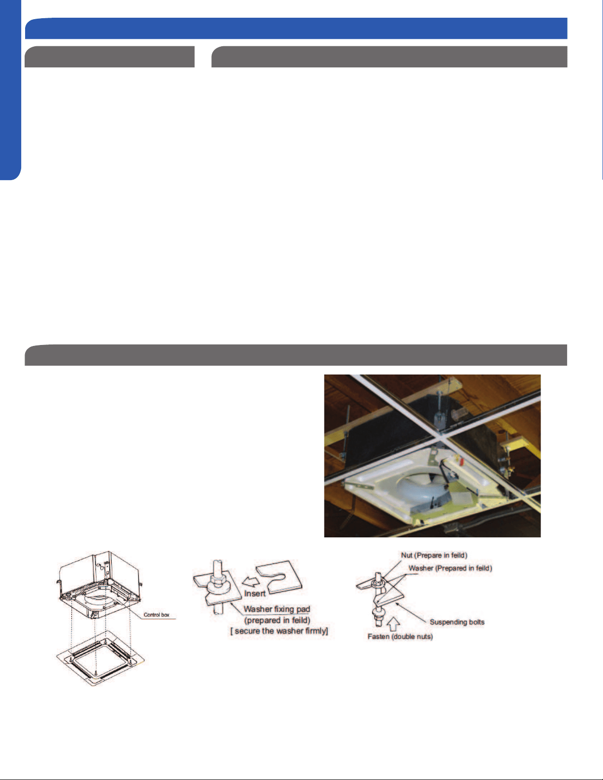
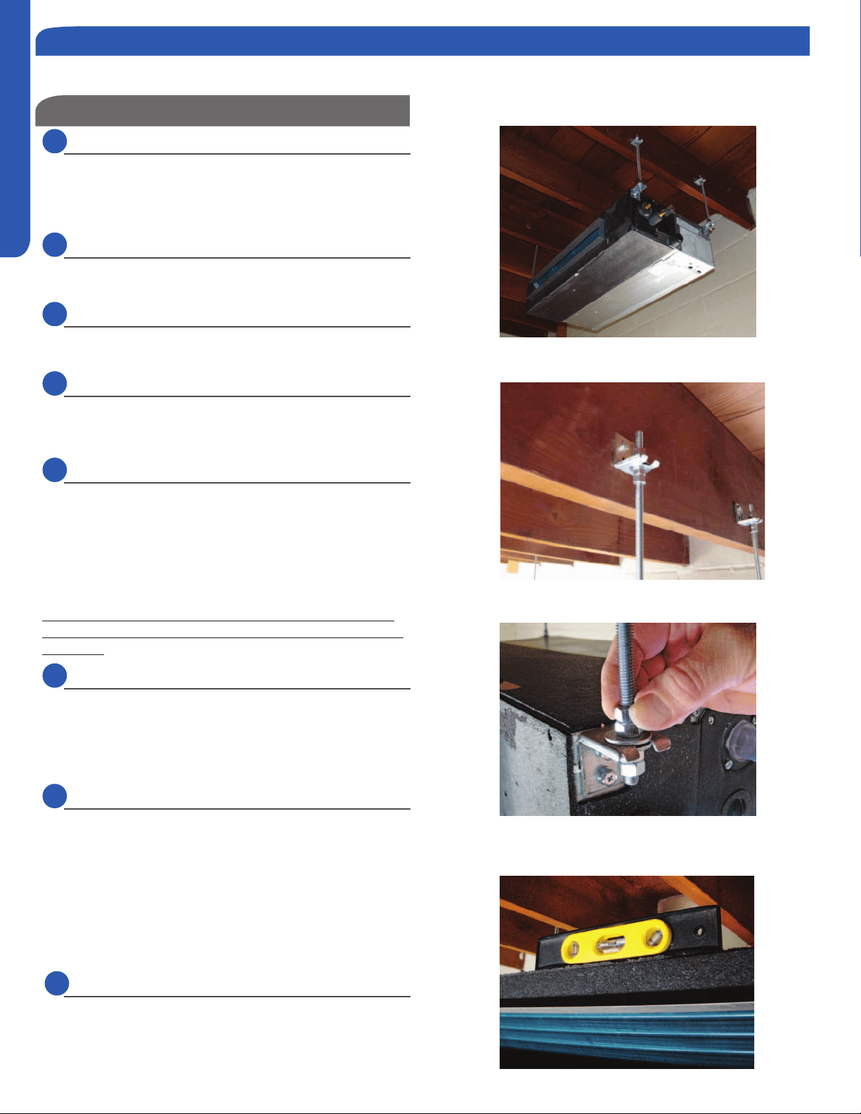
Threaded Rod Mounting Information
The Cassette unit should be mounted to the building
structure using threaded rods. The threaded rods should
have washers and nuts to allow the height and level of the
cassette to be adjusted.
items. The materials required for mounting to the brackets
on the cassette assembly include:
4- 3/8” Threaded Rods
4- Mounting Brackets
8- Washers
8- Nuts (Double nut the assembly as shown)
INSTALLATION
PAGE 17
ENGLISH
Step By Step Guide To Cassette Installation
Step 2 - Installation of the Cassette Unit
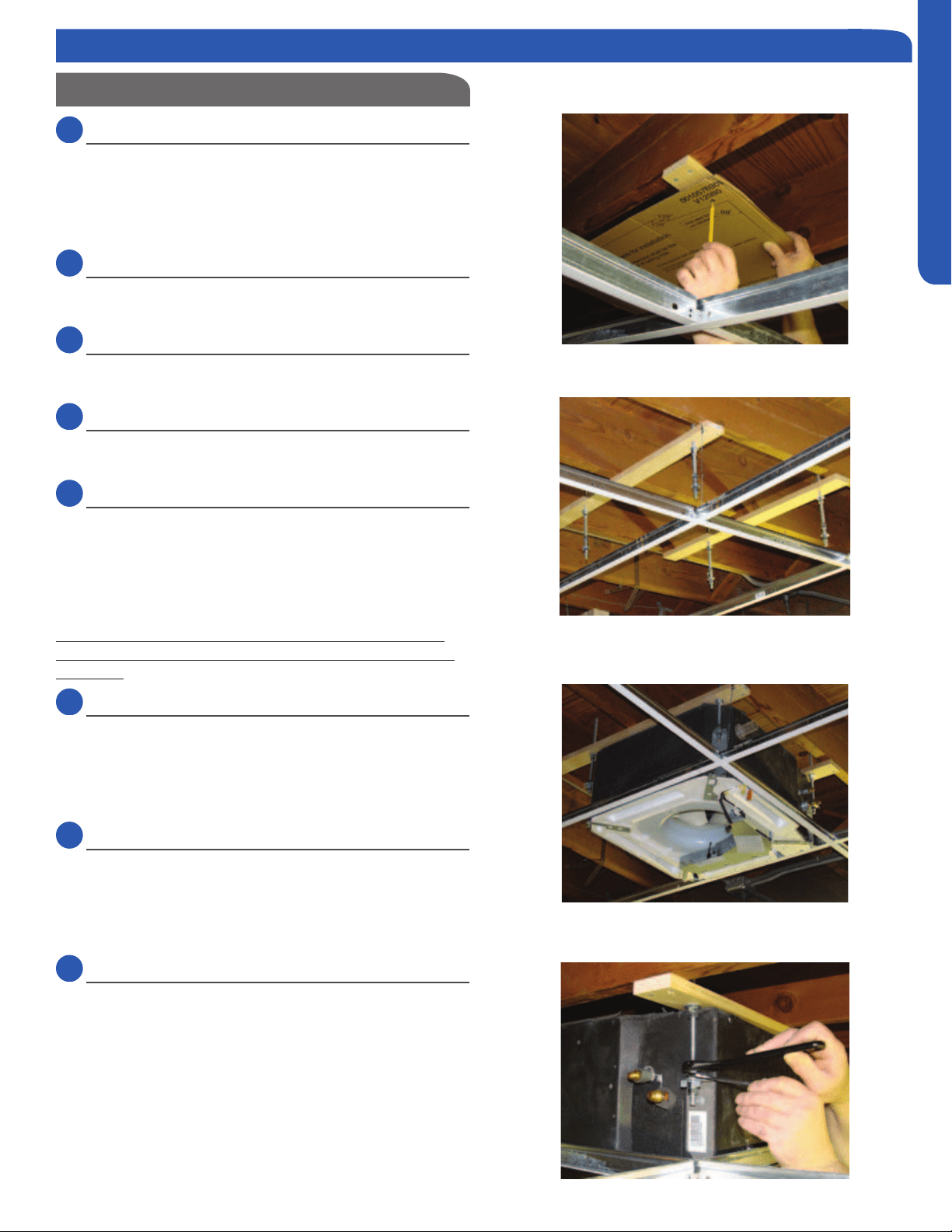
2.1
Step 2.1
Use cardboard template to locate center point of cassette for
mounting. Use a plumb bob and string to position cassette
by referencing center hole of template. Mark the mounting
positions of the threaded rods using the guides on the
cardboard template.
2.2
Step 2.2
Install threaded rods to structure using appropriate
fasteners.
2.3
Step 2.3
Lift the cassette and position the threaded rods into the 4
mounting clips on each corner of the cassette unit.
2.4
Step 2.4
Using a level, adjust the nuts on the threaded rods to obtain a
level reading across the bottom of the cassette unit.
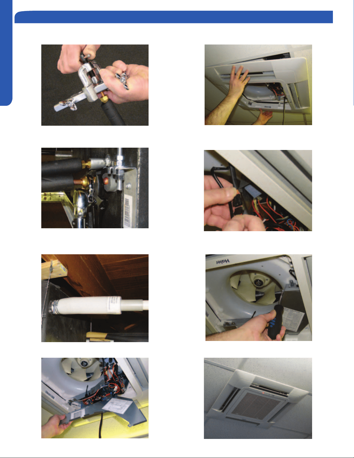
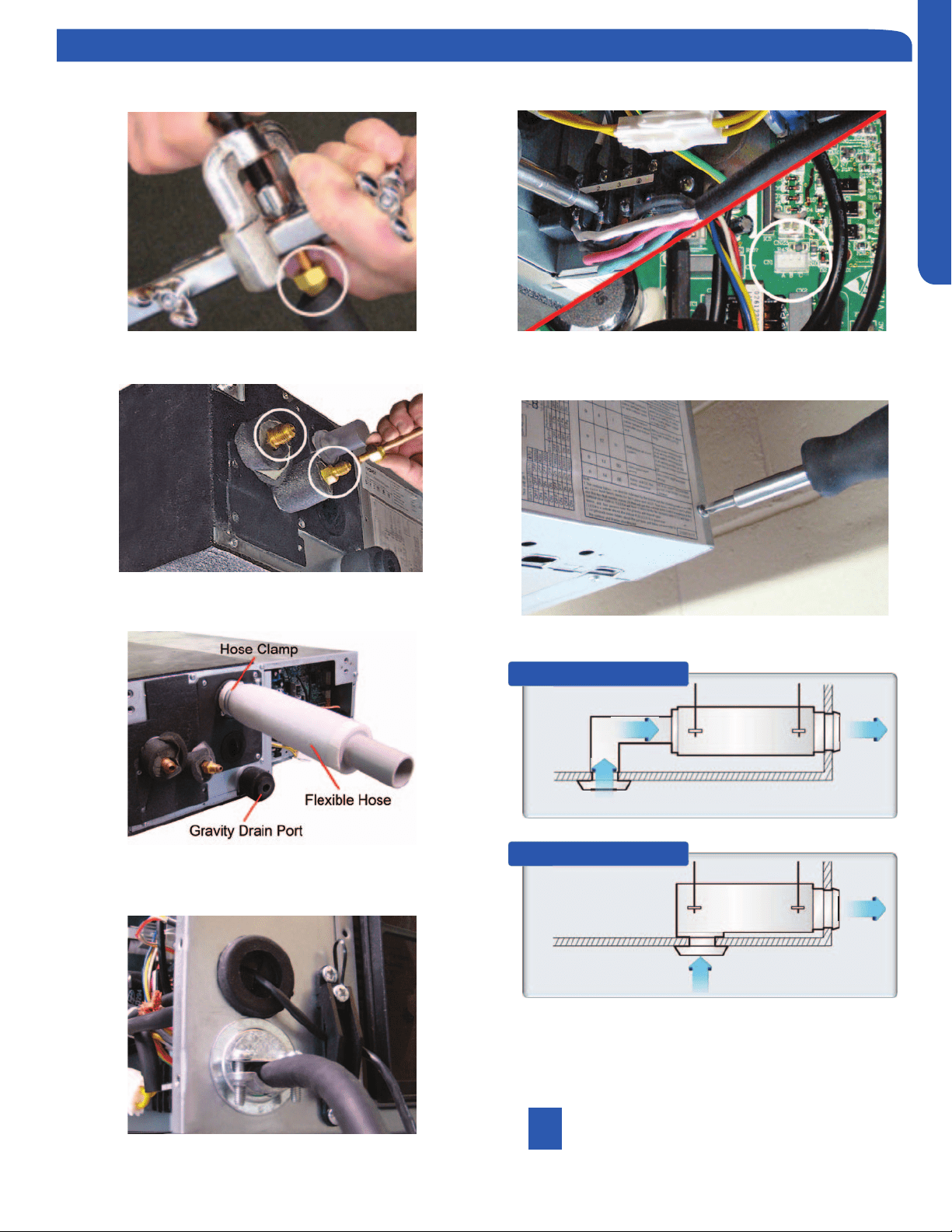
2.5
Step 2.5A & 2.5B
Prior to routing the refrigerant lines to the unit, install the
the ends of the refrigerant line connections at the cassette.
Holding gas should leak out.
Using a torque wrench, torque the ttings to the proper
specications. (See Outdoor Unit Section for are torque
settings.)
2.6
Step 2.6
cassette unit to the condensate pump discharge pipe of
the cassette. Tighten the clamp securely. Using 3/4 “ PVC,
system.
2.7
Step 2.7
Remove the electrical box cover. Remove the rubber
grommet and insert a 1/2 inch electrical connector and
reducing washer. Route electrical wiring into cassette unit.
Connect to wire terminas as indicated in schematic drawing.
(USE 14 AWG Stranded wire only.)
2.8
Step 2.8A & 2.8B ,C, D
Connect Louver assembly to cassette assembly. Connect
wires from louver to the harness on the cassette assembly.
There are two wire connections. (See photo for connections.)
Secure louver with four screws.
Reinstall electrical box cover.
Install return air grille into louver assembly.
Installation is now complete.
Step 2.1
Step 2.3
Step 2.2
Step 2.4
INSTALLATION
PAGE 18
ENGLISH
Step 2 - Installation of the Cassette Unit
Step 2.5B
Step 2.7
Step 2.8B
Step 2.5A
Step 2.6
Step 2.8A
Step 2.8D
Step 2.8C
INSTALLATION
PAGE 19
ENGLISH
Step 3 - Electrical Connections
Step 4 - Louver Installation
Step 5 - Pull Vacuum on System
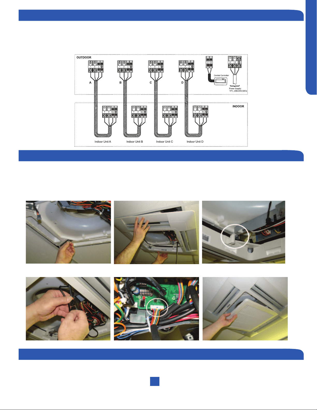
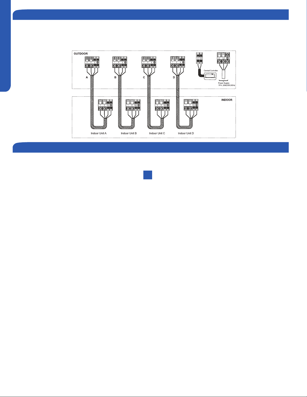
Electrical Connections Indoor and Outdoor Units
14 AWG Stranded Wire Only. (Central Controller Not Used)
Maintain 10 feet of separation between TV and any Radio wiring.
To mount the louver cover onto the cassette assembly. Install 2 screws at the keyhole slot positions shown in the
(White circle.) Install remaining 2 screws and tighten the 4 screws. Connect electrical plugs to socket shown below.
Install the electrical cover box and then snap the return air grille into position.
See Step 4.2 of the outdoor unit installation section for how to pull a vacuum.
Indoor Cassette Unit Installation Complete
INSTALLATION
PAGE 20
ENGLISH
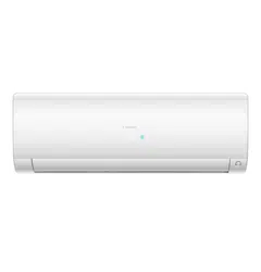
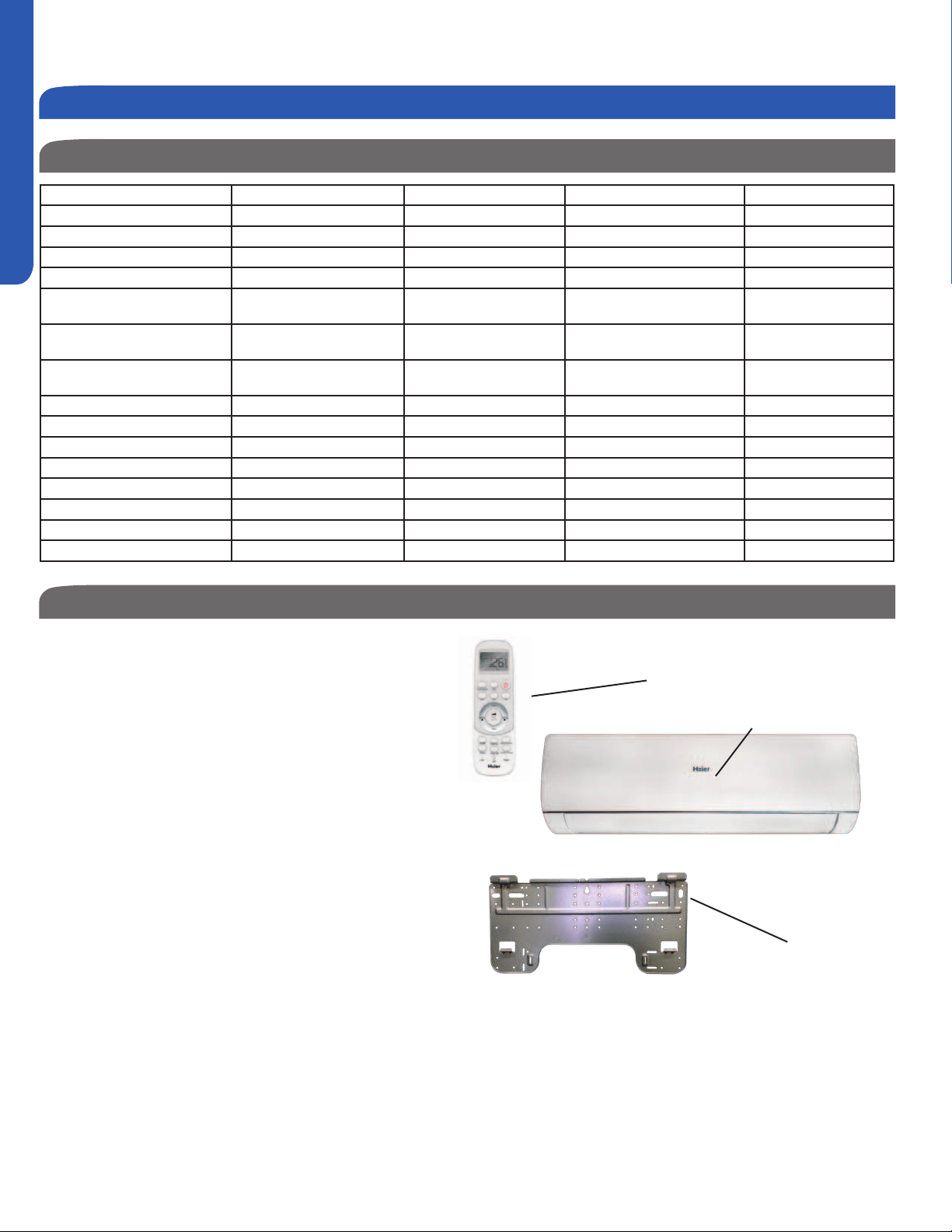
Wall Mount Product Information
Introduction - Overview
The Wall Mount Indoor Air Handler consists of a single
compact unit, operated via a factory supplied remote control.
A display indicator located on the front panel of the unit
provides temperature and operating modes of the system. It
can also display error code conditions of the system.
The wall mount unit receives 230 volt line voltage from a
terminal connection at the outdoor condensing unit. There is
no requirement for independent line voltage connections.
Piping to the unit may be routed from one of several
directions. (Left, left back, left down, right, right back and
right down.)
A motorized louver at the front of the unit is controlled via the
remote control. The louver may be set to either oscillate or
remain in a stationary position.
Manual vanes located behind the louver may be set to help
Factory Supplied
Remote
Display
Mounting Bracket
Indoor Unit Installation - Wall Mount
Wall Mount Indoor Unit Specications
Indoor AW07LC2VHA AW09LC2VHA AW12LC2VHA AW18LC2VHA
Rated Cooling Capacity Btu/hr 7,000 9,000 12,000 18,000
Rated Heating Capacity Btu/hr 8,000 10,000 13,000 19,000
Voltage, Cycle, Phase V/Hz/- 208-230/60/1 208-230/60/1 208-230/60/1 208-230/60/1
Fan Speed Stages 5+Auto 5+Auto 5+Auto 5+Auto
Quiet) CFM
410/350/295/235/205 410/350/295/235/205 440/380/320/265/215 636/530/483/430/383
Motor Speed (Turbo/High/Med/
Low/Quiet) RPM
1050/950/800/650/600 1050/950/800/650/600 1100/1000/850/700/620 1100/950/850/750/600
Indoor Sound Level dB (Turbo/
High/Med/Low/Quiet)
43/38/33/26/22 43/38/33/26/22 44/39/34/27/23 48/45/40/35/30
Dimension: Height in (mm) 11 (280) 11 (280) 11 (280) 12 3/4 (332)
Dimension: Width in (mm) 33 5/8 (855) 33 5/8 (855) 33 5/8 (855) 39 1/4 (997)
Dimension: Depth in (mm) 8 1/16 (204) 8 1/16 (204) 8 1/16 (204) 9 1/4 (235)
Weight (Ship/Net)- lbs (kg) 26.8/22(12.2/10) 26.8/22(12.2/10) 26.8/22(12.2/10) 35.3/28.6 (16/13)
Connections Flare Flare Flare Flare
Liquid O.D. in 1/4 1/4 1/4 1/4
Suction O.D. in 3/8 3/8 3/8 1/2
Drainpipe Size O.D. in 5/8 5/8 5/8 5/8
INSTALLATION
PAGE 21
ENGLISH
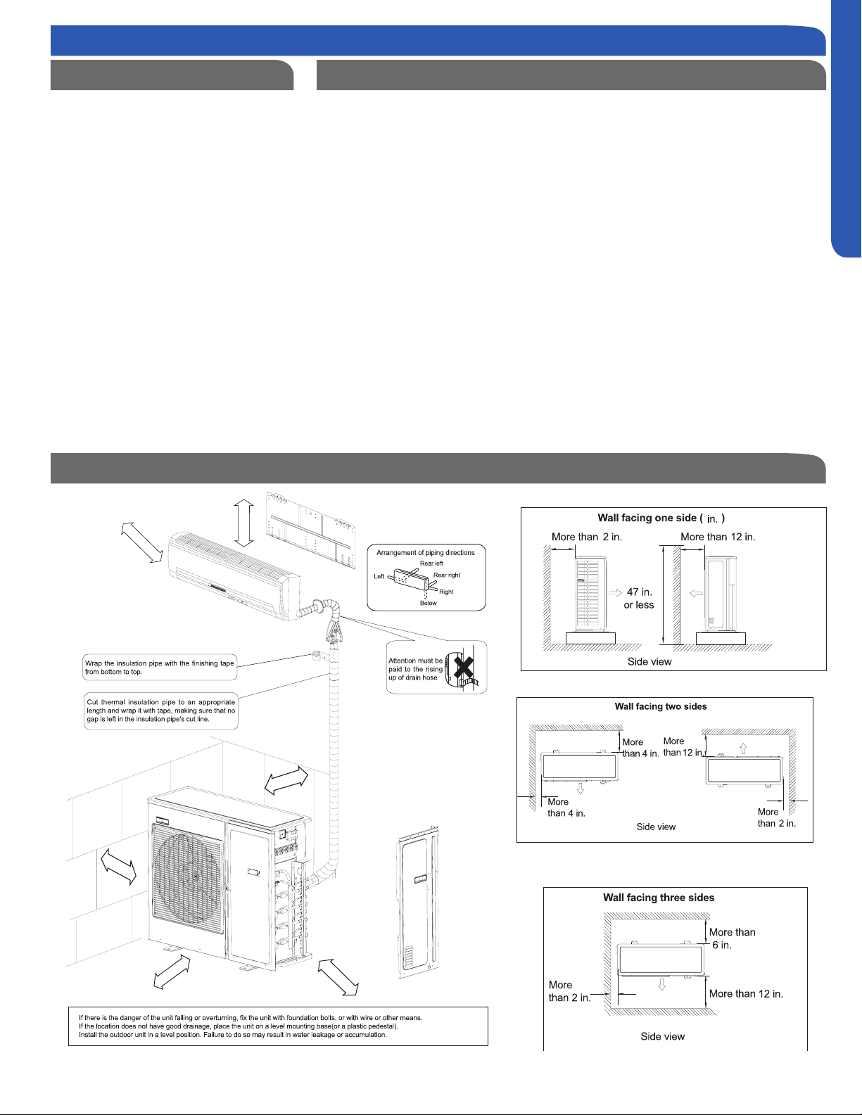
This picture is for reference only. Your product may look
operation of the unit to the user according to this manual.
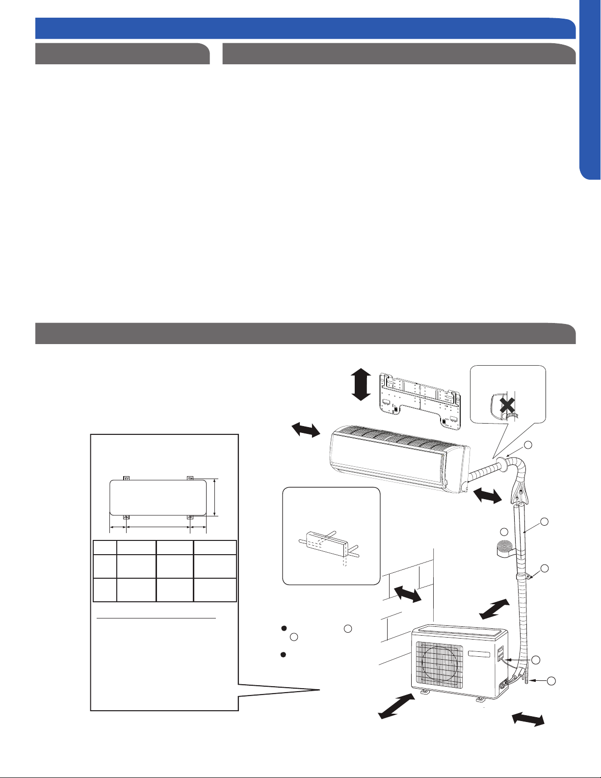
Clearances of Indoor and Outdoor Units
F
A
C
E
D
The marks from to
in the figure are the
parts numbers.
The distance between
the indoor unit and the
floor should be more
than 6.5 ft.
The models adopt HFC free refrigerant R410A
more than
4 in.
more than 4 in.
more than 4 in.
more than 8 in.
more than
6 in.
more than 10 in.
more than
24 in.
A
G
Arrangement of piping
directions
Rear left
Left
Rear
right
Right
Below
G
Attention must be paid to
the rising up of drain hose
X XY
Z
For: 09k 12k 18k 24k
Mounting the Outdoor Unit
Mount the unit to concrete or a block
horizontally.
When mounting the unit to a wall or
roof, take strong winds and other
environmental conditions into
consideration when securing.
the unit using a vibration-proof mat.
Outdoor unit mounting
dimensions (Unit: mm/inch)
X Y Z
12k
5 ½”
140
mm
500mm
256mm
18k
113.5mm
583mm
319.5mm
Step 1 - Preparation
*Single zone outdoor unit shown for illustration purposes ONLY.
Required Tools for Installation Procedure for Selecting the Location
Drill
Wire Snipper
Hole Saw 2 3/4”
Vacuum pump
Soap-and-water solution or gas leakage
detector
Torque wrench
17mm, 22mm, 26mm
Tubing cutter
Flaring tool
Razor knife
Measuring tape
Level
Micron gauge
Nitrogen
Mini-Split AD-87 Adapter (1/4” to 5/16”)
A - Non-adhesive Tape
B - Adhesive Tape
C - Saddle (L.S.) with screws
D - Electrical wiring
E - Drain hose (Included)
F - Insulation
G - Piping hole cover (Included)
Note:
1) R-410A refrigerant is a safe, nontoxic and
there is a concern about a dangerous level
of refrigerant concentration in the case of
refrigerant leakage, add extra ventilation.
Choose a place solid enough to bear the
weight of the unit.
Avoid choosing a site with steam or heat
When mounting the unit always maintain
proper clearances
Position so that the condensate can easily
drain.
An area where the piping can be
connected with the outdoor unit.
the room.
Place a minimum distance of 3 ft. from
televisions, radios, wireless apparatuses,
When mounting the remote controller on
a wall, position it where the indoor unit can
receive the remotes infrared signals when
passage and no obstructions around the
air inlet and air outlet.
The site must be free from the possibility
place.
INSTALLATION
PAGE 22
ENGLISH
Step 2 - Installation of the Wall Mount Unit
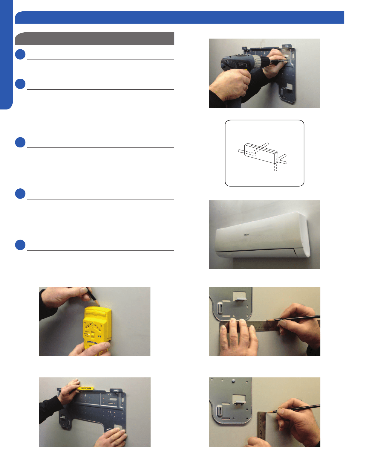
Attaching the Mounting Plate to the Wall
2.1
Step 2.1
Using a stud sensor, locate and mark the stud positions in the
wall where the indoor unit is to be mounted.
2.2
Step 2.2
Place the mounting plate on the wall in the desired location
taking into account the minimum clearances necessary for
proper operation.
Using a level, verify the mounting plate is horizontal and mark
the screw locations.
2.3
Step 2.3
Screw the mounting plate to the wall.
The piping for the indoor unit may be routed to the unit from
one of several directions. Left, Left Rear, Right, Right Rear, or
Below (Illustration 1).
2.4
Step 2.4
Knockouts are provided on the case for Left, Right, and Right
Below.
Drilling the hole through the wall for left rear or right rear
installation
2.5
Step 2.5A & 2.5B
Measure and mark the location where the piping hole is to be
drilled.
Step 2.1
Step 2.5BStep 2.2
Step 2.3
Step 2.4
Step 2.5A
Piping Exit Options
Rear left
Left
Rear
right
Right
Below
Illustration 1
INSTALLATION
PAGE 23
ENGLISH
Step 2.6
Step 2.7
Step 2.8A
Step 2.8B
2.6
Step 2.6
Drill the piping hole using a hole saw of the correct diameter.
Angle the drill with a downward pitch to the outside wall so
that the outside hole will be ¼” lower than the inside hole,
giving the hole the proper angle for condensate drainage.
2.7
Step 2.7
inside wall.
properly behind the wall unit housing.
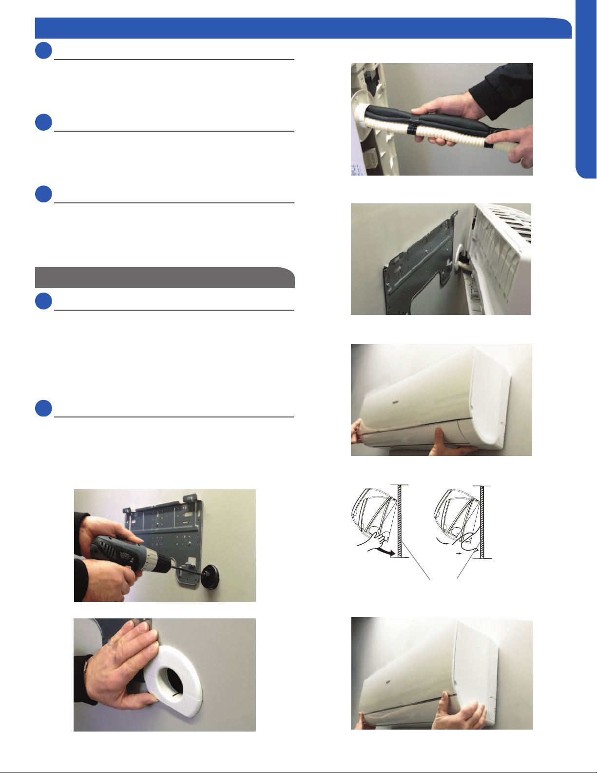
2.8
Step 2.8A & 2.8B
Bundle the refrigerant piping, drain piping and wiring with
tape and pass the bundle through the piping hole.
available in the indoor unit to make the connections to the
terminal block.
Mounting the Indoor Unit Onto the Wall Plate
2.9
Step 2.9
With the top of the indoor unit closer to the wall, hang the
indoor unit on the upper hooks of the mounting plate. Slide
the unit slightly side to side to verify proper placement of the
indoor unit on the mounting plate. Rotate the lower portion
of the indoor unit to the mounting plate, and lower the unit
onto the lower hooks of the mounting plate. (Illustration 2)
Verify the unit is secure.
2.10
Step - 2.10
Slightly raise the entire unit vertically, pull the lower portion
the upper hooks of the wall plate.
Step 2.9
Step 2.10
mounting plate
Illustration 2
Step 2 - Installation of the Wall Mount Unit
INSTALLATION
PAGE 24
ENGLISH
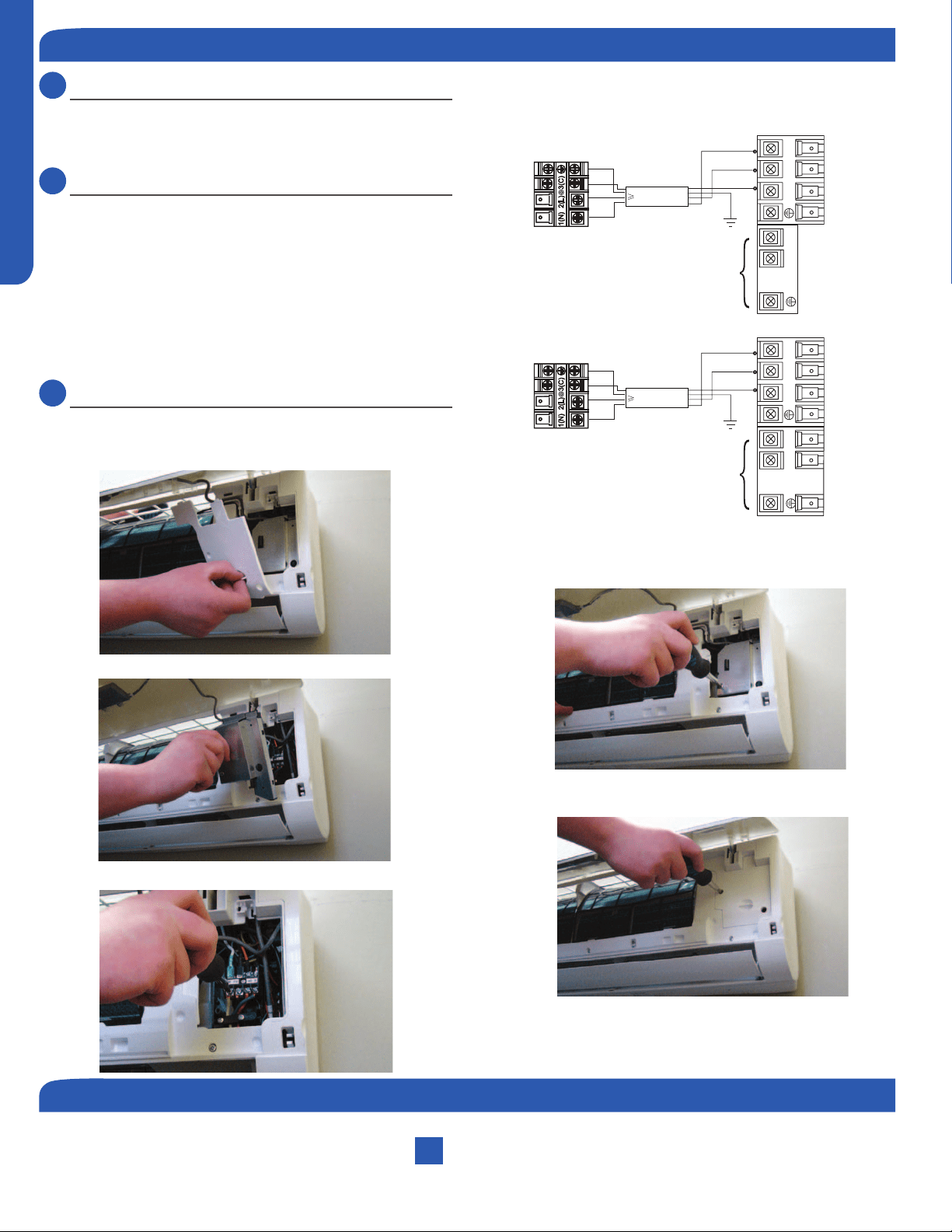
3.1
Step - 3.1A & 3.1B
To make the electrical connections for the indoor unit, two
cover plates must be removed. Raise the front cover to
access the screws to remove these covers.
3.2
Step - 3.2 & 3.2A & 3.2B
Access the four conductor cable through the cover plate
opening and make the wiring connections noting the wire
color used on each terminal. The color of each wire must
match the same positions on the terminal block of the
outdoor unit. (Illustration 3)
Failure to wire the system correctly may lead to improper
operation or component damage.
3.3
Step - 3.3A & 3.3B
After the terminal block wiring is completed, replace both
cover plates.
Step 3.3A
Step 3.3B
Step 3.1A
Step 3.1B
Outdoor unit
3
2
Power
Wiring
1
)
(
N
)
(L
)
(
C
3
2
1
)
(
N
)
(
L
)
(
C
Indoor uni
t
3wire 14AWG
Control Wiring
Outdoor unit
3
2
Power
Wiring
1
)
(
N
)
(L
)
(
C
2
1
)
(
N
)
(
L
Indoor uni
t
3wire 14AWG
Control Wiring
Illustration 3
Step 3.2
Step 3 - Electrical Connections
Indoor Wall Mount Unit Installation Complete
Step 4 - Pull Vacuum on System
See Step 4.2 of the outdoor unit installation section for how to pull a vacuum.
INSTALLATION
PAGE 25
ENGLISH
Slim Duct Indoor Unit Specications
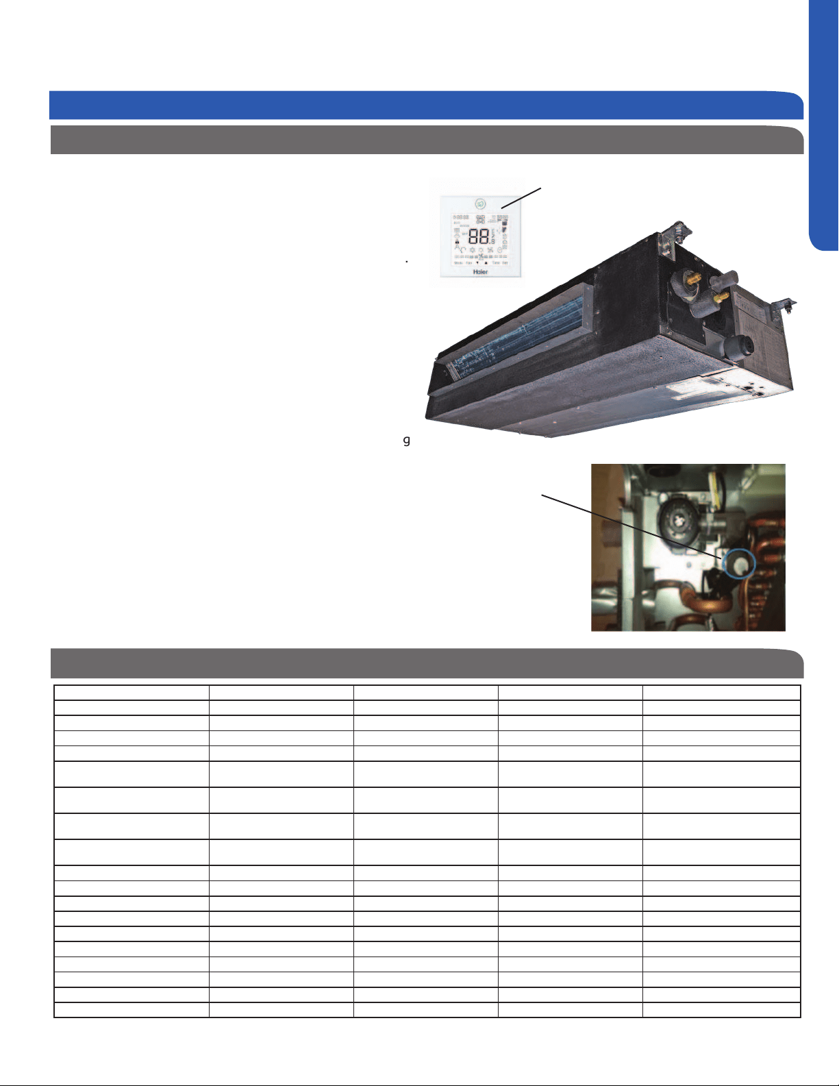
Slim Duct Product Information
The Slim Duct Indoor Air Handler ships consisting of a single
assembly. The Slim Duct indoor unit is operated via a factory
supplied wired remote control.
that are located at all four corners of the Slim Duct assembly.
The Slim Duct unit receives 230 volt line voltage from a
connection at the outdoor condensing unit. There is no
requirement for independent line voltage connections.
The Slim Duct unit has a built-in condensate pump and
Duct unit. This hose connects the Slim Duct condensate
drain outlet to the building’s condensate drain system.
Included with the Slim Duct unit is factory provided insulating
tape. This tape should be placed over the refrigerant piping
connections at the indoor unit to prevent sweating.
Built-in
Condensate
Pump and
Float Switch
Wired Controller
Indoor Unit Installation - Slim Duct
Indoor AD07SL2VHA AD09SL2VHA AD12SL2VHA AD18SL2VHA
Rated Cooling Capacity Btu/hr 7,000 9,000 12,000 18,000
Rated Heating Capacity Btu/hr 8,000 10,000 13,000 19,000
Voltage, Cycle, Phase V/Hz/- 208-230/60/1 208-230/60/1 208-230/60/1 208-230/60/1
Fan Speed Stages 5+Auto 5+Auto 5+Auto 5+Auto
Quiet) CFM
353/312/270/230/188 353/312/270/230/188 400/353/282/247/218 540/500/447/365/306
Motor Speed (Turbo/High/Med/Low/
Quiet) RPM
950/850/750/650/550 950/850/750/650/550 1050/950/800/700/600 1050/950/850/750/650
Max. External Static Pressure in.W.G
(Pa)
0.16 (40) 0.16 (40) 0.16 (40) 0.16 (40)
Indoor Sound Level dB (Turbo/High/
Med/Low/Quiet)
35/33/29/26/21 35/33/29/26/22 38/35/29/26/23 31/29/23/29/25
Dimension: Height in (mm) 7 5/16 (185) 7 5/16 (185) 7 5/16 (185) 7 5/16 (185)
Dimension: Width in (mm) 33 7/16 (850) 33 7/16 (850) 33 7/16 (850) 46 1/16 (1170)
Dimension: Depth in (mm) 16 9/16 (420) 16 9/16 (420) 16 9/16 (420) 16 9/16 (420)
Weight (Ship/Net)- lbs (kg) 47.2/36.8 (21.4/16.7) 47.2/36.8 (21.4/16.7) 47.2/36.8 (21.4/16.7) 61.8/48.5(28/22)
Connections Flare Flare Flare Flare
Liquid O.D. in 1/4 1/4 1/4 1/4
Suction O.D. in 3/8 3/8 3/8 1/2
Drainpipe Size O.D. in 1 1/4 1 1/4 1 1/4 1 1/4
Internal Condensate Pump Standard Standard Standard Standard
Max. Drain-Lift height in(mm) 27 9/16 (700) 27 9/16 (700) 27 9/16 (700) 27 9/16 (700)
Introduction - Overview
INSTALLATION
PAGE 26
ENGLISH
Air Delivery Clearances
Make certain to maintain proper clearances around the Slim
Duct unit.
Inadequate clearances can cause system freezing and
temperature control problems.
Service and Maintenance Clearances
Make sure there are adequate clearances for future
maintenance and service. Allow enough room to access the
condensate pump assembly and the electrical control box.
Electrical Power
Follow all local codes and regulations when installing electrical
wiring.
Route required electrical power to area where the Slim Duct
unit is to be located. Maintain at least a 10 foot separation
between TV and Radio wiring and the power to the indoor
unit.
14 Gauge AWG stranded wire should be used to make the
electrical connection between indoor and outdoor units.
This wiring will serve to power the indoor unit and establish a
communication link between indoor and outdoor units.
The wiring is connected at the indoor unit electrical terminal
blocks screws 1, 2, 3 and ground. There should be no
splices in the wires connected to terminals 1 or 3 as these
serve as communication signal wires and electrical power
power to the indoor unit, break wire 2 only.
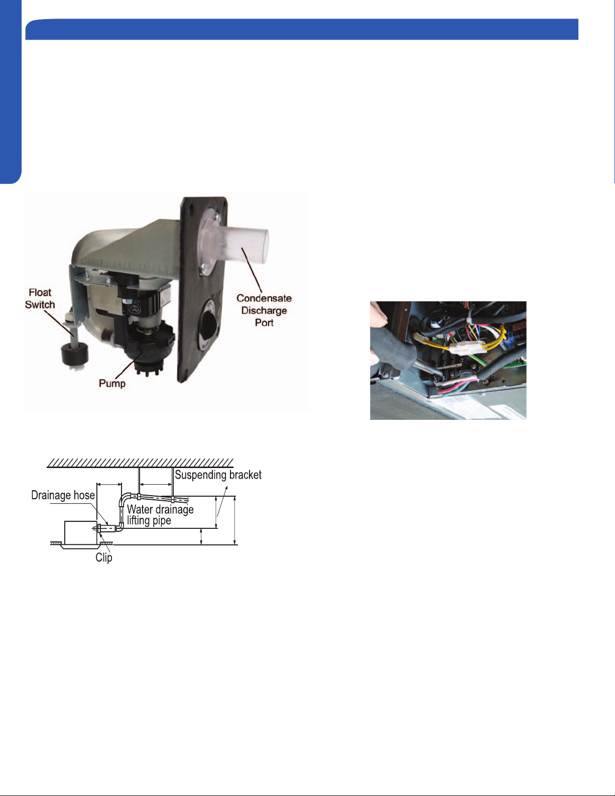
Condensate Handling
The Slim Duct unit has a built-in condensate pump and water
level safety switch. There are also two optional ports for
gravity drainage. The condensate pump is rated to lift water
up to 24” from the point of discharge on the Slim Duct unit.
The Slim Duct unit comes with a grey connection hose
with clamp. This hose is connected to the Slim Duct unit
condensate discharge hose port. The other end of the hose is
sized to accept 3/4 inch PVC piping.
Introduction - Overview
here:
12 in. below
3-5 ft.
11 in. unde
r
8.6 in.
8.6 in.
19.6 in. below
INSTALLATION
PAGE 27
ENGLISH
Procedure for Selecting the LocationRequired Tools for Installation
Drill
Wire Snipper
Hole Saw 2 3/4”
Vacuum pump
Soap-and-water solution or gas leakage
detector
Torque wrench
17mm, 22mm, 26mm
Tubing cutter
Flaring tool
Razor knife
Measuring tape
Level
Micron gauge
Nitrogen
Mini-Split AD-87 Adapter (1/4” to 5/16”)
A - Non-adhesive Tape
B - Adhesive Tape
C - Saddle (L.S.) with screws
D - Electrical wiring
E - Drain hose (Included)
F - Insulation
G - Piping hole cover (Included)
Note:
1) R-410A refrigerant is a safe, nontoxic
if there is a concern about a dangerous
level of refrigerant concentration in the
case of refrigerant leakage, add extra
ventilation.
where you have enough space to position
the unit.
Place where the drainage pipe can be
properly positioned.
Place where the inlet and outlet air of the
indoor unit will not be blocked.
Do not install the unit in a place with
heavy oil or moisture (e.g. - kitchens and
workshops)
Do not install in a location with
destructive gas (such as sulfuric acid gas)
or pungent gas (thinner and gasoline) are
used or stored.
Choose a place solid enough to bear the
weight and vibration of the unit and where
Install where there are no expensive
items like a television or piano below the
indoor unit.
Leave enough space for maintenance.
Install at least 3 ft. away from televisions
and radios to avoid interference.
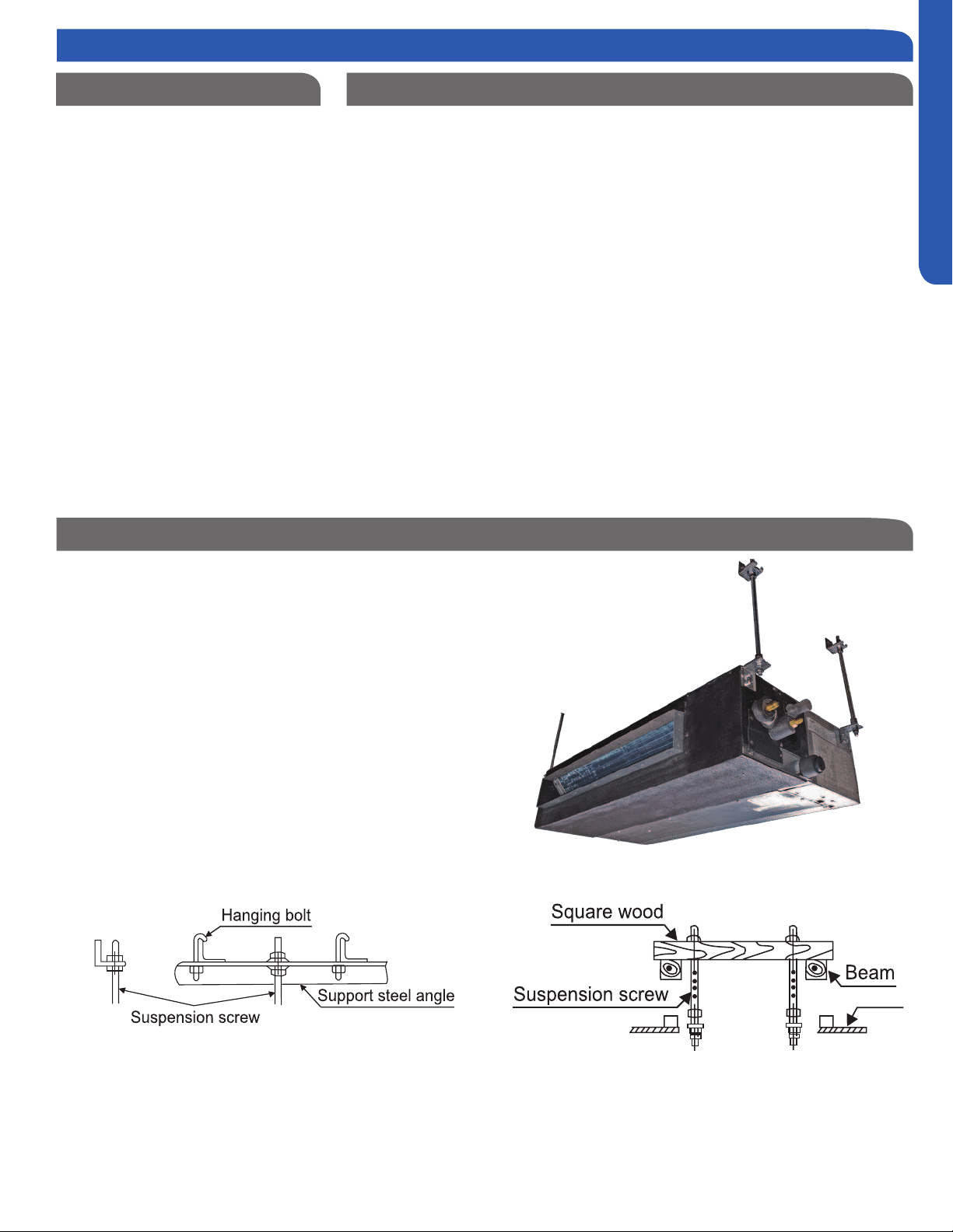
Threaded Rod Mounting Information
The Slim Duct unit should be mounted to the building
structure using threaded rods. The threaded rods should
have washers and nuts to allow the height and level of the
Slim Duct unit to be adjusted.
items. The materials required for mounting to the brackets
on the Slim Duct unit include:
4- 3/8” Threaded Rods
4- Mounting Brackets
Washers
Nuts (Double nut the assembly as shown in steps 2.2 & 2.3)
Step 1 - Preparation
INSTALLATION
PAGE 28
ENGLISH
Step By Step Guide To Slim Duct Unit Installation
2.1
Step 2.1
Determine and mark the position of where the Slim Duct
unit is to be installed. Install the hardware necessary to
mount the threaded rods. Always select a location strong
enough to support the indoor Slim Duct unit.
2.2
Step 2.2
Install the threaded rods to the hardware attached to the
structure.
2.3
Step 2.3
Lift the Slim Duct unit and position the threaded rods into
the 4 mounting clips, one located on each corner of the unit.
2.4
Step 2.4
Using a level, adjust the nuts on the threaded rods to obtain
level readings both side to side and front to back on the Slim
Duct unit.
2.5
Step 2.5 - 2.5A
Prior to routing the refrigerant lines to the unit, install the
the ends of the refrigerant line connections at the Slim Duct
unit. Holding gas should leak out. Attach the refrigerant lines
to the air handler.
Using a torque wrench, torque the ttings to the proper
specications. (See Outdoor Unit Section for are torque
settings.)
2.6
Step 2.6
Duct unit to the condensate pump discharge pipe of the
Slim Duct unit. Tighten the clamp securely. Using 3/4 “ PVC,
system.
2.7
Steps 2.7 - 2.7A - 2.7B
Route the 14AWG stranded 4 conductor power/
communication cable and the wired remote cable to the air
handler. Use reducing washers and appropriate connector
to attach the power/communication cable to the unit. The
wired remote cable will enter the unit through a rubber
grommet. The 4 conductor cable connects to the terminal
block at terminals 1, 2, 3, and ground. The wired remote
cable connects to the air handler main board at connector
CN1. Re-install electrical box cover.
The unit is now ready for connection to the ductwork.
inlet or bottom side inlet.
Step 2.1
Step 2.3
Step 2.2
Step 2.4
2.8
Step 2.8
Step 2 - Installation of the Slim Duct Unit
INSTALLATION
PAGE 29
ENGLISH
Step 2.5A
Step 2.7
Step 2.5
Step 2.6
Step 2.7A
INSTALLATION IS NOW COMPLETE
Step 2.8
Rear side air inlet
Bottom side air inlet
Diffuser
Return Duct
Diffuser
Return Duct
Step 2.7B
Re-install electrical box cover
Step 2 - Installation of the Slim Duct Unit
INSTALLATION
PAGE 30
ENGLISH
Electrical Connections Indoor and Outdoor Units
14 AWG Stranded Wire Only. (Central Controller Not Used)
Maintain 10 feet of separation between TV and any Radio wiring.
See Step 4.2 of the outdoor unit installation section for how to pull a vacuum.
Indoor Slim Duct Unit Installation Complete
Step 3 - Electrical Connections
Step 4 - Pull Vacuum on System
REMOTE CONTROL FUNCTIONS
PAGE 31
ENGLISH
3
8
6
19
4
17
18
14
13
109
7
5
16
2
15
11
12
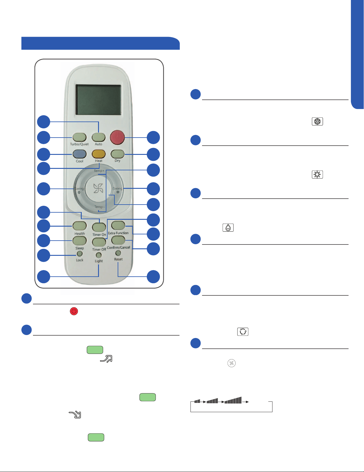
1
1
Power Button
Press the ON/OFF button on the remote control to start
the unit.
2
TURBO/QUIET Button
The TURBO function is used for fast heating or cooling.
Press the TURBO/QUIET
button once and the remote
control will display the TURBO
icon on the bottom right
side of the remote display and switch the unit to the TURBO
function.
The QUIET function may be used when silence is needed for
fast rest or reading. Press the TURBO/QUIET
button
again to switch to QUIET mode and the remote control will
display the QUIET
icon on the bottom left side of the
remote display.
Press the TURBO/QUIET
button a third time to cancel
TURBO/QUIET and return to normal operation.
Note:
TURBO/QUIET modes are only available when the unit is un-
der cooling or heating mode (not for auto or fan mode).
Running the unit in QUIET mode for a long period of time
may cause the room temperature to not reach the set
temperature. If this occurs, cancel QUIET mode and set the
fan speed to a higher setting.
3
COOL Button
In COOL mode, the unit operates in cooling. When FAN is
set to AUTO, the air conditioner automatically adjusts the
fan speed according to room temperature. The
will be
displayed during COOL mode.
4
HEAT Button
In HEAT mode, warm air will blow out after a short period of
the time due to cold-air prevention function. When FAN is
set to AUTO, the air conditioner automatically adjusts the
fan speed according to room temperature. The
will be
displayed during HEAT mode.
5
DRY Button
DRY mode is used to reduce humidity. In DRY mode, when
room temperature becomes lower than temp. setting +2°F,
unit will run intermittently at LOW speed regardless of FAN
setting. The
will be displayed during DRY mode.
6
Temperature +/- Buttons
Temp + Every time the button is pressed, the temperature
setting increases.
Temp - Every time the button is pressed, temperature
setting decreases.
The operating temperature range is 60°F-86°F.
7
AUTO Button
Under the mode of auto operation, the air conditioner will
automatically select Cool, Heat, or Fan operation according
to set temperature. When FAN is set to AUTO the air condi-
tioner automatically adjusts the fan speed according to room
temperature. The
will be displayed during AUTO mode.
8
FAN Button
Fan speed selection
Press the FAN
button. For each press, fan speed changes
as follows:
Remote control:
LOW
MED HI
AUTO
Display
circulated
The air conditioner fan will run according to the displayed fan
speed.
When FAN is set to AUTO, the air conditioner automatically
adjusts the fan speed according to room temperature.
Functions
Remote Controller
REMOTE CONTROL FUNCTIONS
PAGE 32
ENGLISH
9
Louver SWING Button - Vertical
Air Flow Direction Adjustment
Press the SWING UP/DOWN button to choose the position of
COOL/DRY:
HEAT:
Caution:
It is advisable not to keep the vertical louver in the down-
ward position for an extended period of time in COOL or
DRY mode, otherwise condensate water may form on the
louver.
Note:
When turning the unit on, the remote control will automatically
return the louver to the previous set swing position. When turn-
ing the unit o, the louver will rotate to the full open position
prior to closing.
10
Louver SWING Button - Horizontal
Press the SWING UP/DOWN button to choose the position of
COOL/DRY/HEAT:
'
Caution:
When humidity levels are high, condensate water may
occur at the air outlet if all horizontal louvers are adjusted
to left or right.
Note:
When turning the unit on, the remote control will automatically
return the louver to the previous set swing position. When turn-
ing the unit o, the louver will rotate to the full open position
prior to closing.
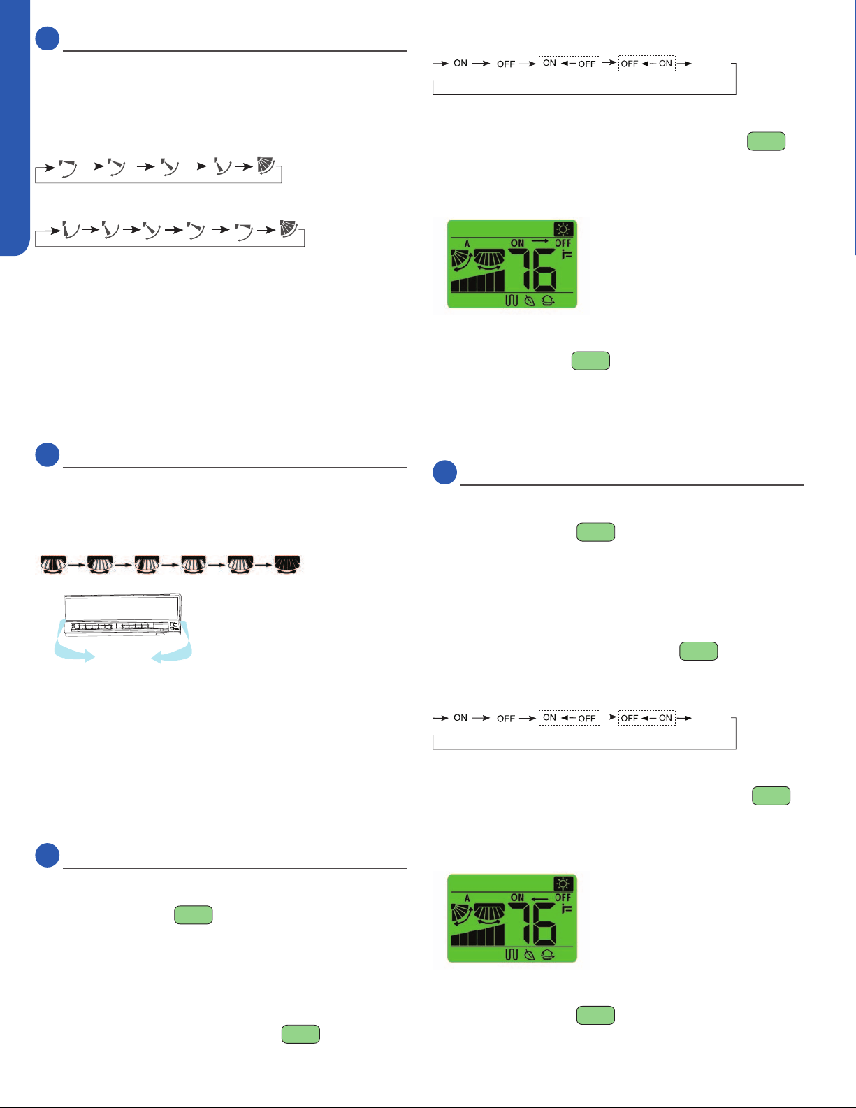
11
Timer ON Button
1. Start the unit and select the desired operating mode.
2. Press the TIMER ON
button to enter the TIMER ON
3. Every time the TIMER ON button is pressed the length of
time increases in 0.5 hour increments between hours 0 and
12, and 1 hour increments for times between hours 12 and
24.
4. Once the desired length of time is selected for the unit to
turn on, press the CONFIRM/CANCEL
this setting.
The remote control display changes as follows:
BLANK
TIMER ON TIMER OFF TIMER ON-OFF
TIMER OFF-ON
0.5h
0.5h 0.5h
0.5h
Cancel TIMER ON setting:
With a TIMER ON set, press the CONFIRM/CANCEL
button once to cancel the TIMER ON.
Turning the unit ON with the TIMER from it being OFF will look
like this on the remote control display:
Note:
Holding the TIMER ON
button down will rapidly cycle
the time. After replacing batteries or a power failure occurs,
the time setting will need to be reset.
According to the Time setting sequence of TIMER ON or
TIMER OFF, either Start-Stop or Stop-Start can be achieved.
12
Timer OFF Button
1. Start the unit and select the desired operating mode.
2. Press the TIMER OFF
button to enter the TIMER OFF
3. Every time the TIMER OFF button is pressed the length of
time decreases in 0.5 hour increments between hours 0
and 12, and 1 hour increments for times between hours 12
and 24.
4. Once the desired length of time is selected for the unit to
this setting.
The remote control display changes as follows:
BLANK
TIMER ON TIMER OFF TIMER ON-OFF
TIMER OFF-ON
0.5h
0.5h 0.5h
0.5h
Cancel TIMER OFF setting:
With a TIMER OFF set, press the CONFIRM/CANCEL
button once to cancel the TIMER OFF.
Turning the unit OFF with the TIMER from it being ON will look
like this on the remote control display:
Note:
Holding the TIMER OFF
button down will rapidly cycle

REMOTE CONTROL FUNCTIONS
PAGE 33
ENGLISH
the time. After replacing batteries or a power failure occurs,
the time setting will need to be reset.
According to the Time setting sequence of TIMER ON or
TIMER OFF, either Start-Stop or Stop-Start can be achieved.
13
SLEEP Button
Sleep mode
Press the Extra Function
button to enter additional
options, cycle the button to display the
icon, the
button to
enter the sleep function.
Sleep Operation Mode
1. SLEEP mode during COOL, DRY modes
One hour after SLEEP mode starts, the temperature will
rise 2°F above set temperature, after another hour, the
temperature rises an additional 2°F. The unit will run for an
is 4°F higher than the initial set temperature. Using this
comfort from your unit while you sleep.
SLEEP operation starts SLEEP operation stops
Approx.6hrs
1 hr
Rises 2
O
F
Rises 2
O
F
Temp.setting
Unit stop
In COOL, DRY mode
1 hr
2. SLEEP mode during HEAT mode
One hour after SLEEP mode starts, the temperature will
decrease 4°F below set temperature, after another hour,
the temperature will decrease an additional 4°F. After an
additional three hours, the temperature will rise by 2°F.
The unit will run for an additional three hours, then turns
temperature. Using this feature will help with achieving
sleep.
SLEEP
operation starts
SLEEP
operation stops
1 hr
1 hr
3 hrs
3 hrs
Rises 3
O
F
Temp.setting
Unit stop
In HEAT mode
Decreases 4
O
F
Decreases 4
O
F
3. In AUTO mode
The unit operates in corresponding sleep mode adapted
to the automatically selected operation mode.
Note:
-When the unit is set to sleep mode, the fan speed will be
set to low speed and cannot be changed.
-When the TIMER function is set, the sleeping function
cannot be set. If the sleeping function has been set, and
the user sets the TIMER function, the sleeping function
will be canceled, and the unit will be set to the timer
function.
14
EXTRA FUNCTION Button
Function:
A) Refresh air - Feature not available on this series.
B) A-B Yard - This will allow you to control two separate units
with a single remote control.
Note: this feature would be setup at the time of installation
by the contractor.
C) Fan Mode - Is indicated by the
icon. Only the fan will
operate in this mode. See section 8 “FAN Button” for
changing the fan settings.
D) Intelligent upward airow, E) Intelligent downward airow,
F) Reset intelligent airow position
1. Press the ON/OFF button on the remote control to turn
the unit on.
Select the desired operating mode.
Press the EXTRA FUNCTION
button to enter ad-
ditional options. Press this button repeatedly to access
the louver settings. The louver icon will cycle through the
following three settings.
Healthy
airflow
upward
Healthy
airflow
downward
Present
position
Select the desired position, then press the CONFIRM/
CANCEL
button to set the function.
Press the EXTRA FUNCTION
button to enter addi-
tional options. Press this button repeatedly to access the
louver settings. Cycle the button to the louver icon “pres-
ent” position, then press the CONFIRM/CANCEL
button to cancel the function.
Notice: Do not reposition the horizontal louver by hand.
This may cause the louver to run incorrectly and not
match the icon displayed on the remote control. If the
minute, then back on, and adjust the louver setting with
the remote control.
Note:
2. In cooling, it is better to select the
mode.
3. In heating, it is better to select the
mode.
4. In cooling and dry modes, using the air conditioner for a
long period of time under high humidity conditions, con-
densate water may form on the grille/louver.

REMOTE CONTROL FUNCTIONS
PAGE 34
ENGLISH
15
HEALTH Button
Feature not available on this series.
16
Conrm/Cancel Button
Function: Setting and canceling timer and other functions.
17
LOCK Button
Used to lock buttons and LCD display
18
LIGHT Button
19
RESET Button
If the remote control is not functioning properly, use a pen
point or similar object to depress this button to reset the
remote.
G) Fahrenheit/Celsius mode shift on unit and remote -
To switch between Fahrenheit and Celsius press the EXTRA
FUNCTION
button until either Celsius or Fahrenheit
is displayed. Press the CONFIRM/CANCEL
button to
apply the change.
H) 50°F low temperature heating - Feature not available on
this series.
I) Electrical heating - Feature not available on this series.


www.Haier.com
Haier America,
Wayne, NJ 07470
©2016 Haier America Trading, LLC.
Model #: 2U18MS2VHB, 3U24MS2VHB,
4U36MS2VHB, AW07LC2VH*, AW09LC2VH*,
AW12LC2VH*, AW18LC2VH*, AD07SL2VH*,
AD09SL2VH*, AD12SL2VH*, AD18SL2VH*
Issued Date: June 2016