Loading ...
Loading ...
Loading ...
INSTALLATION
PAGE 24
ENGLISH
3.1
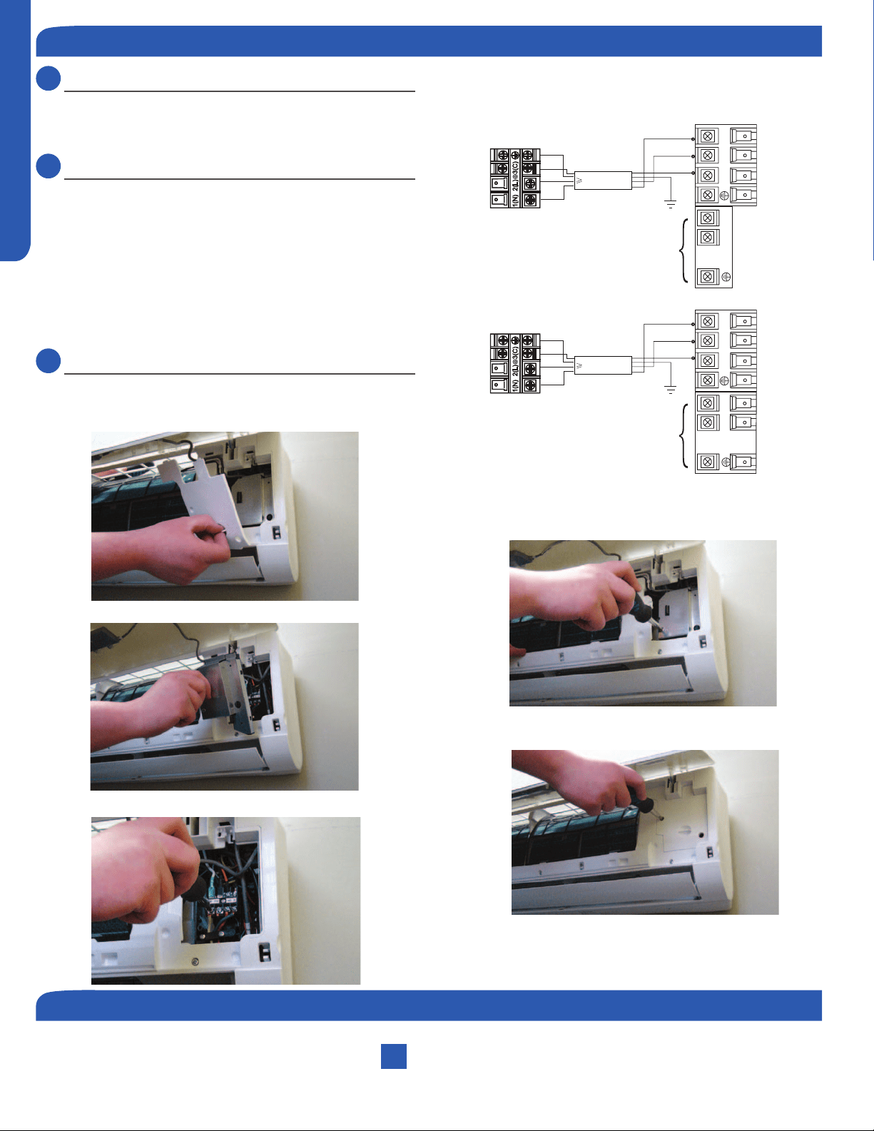
Step - 3.1A & 3.1B
To make the electrical connections for the indoor unit, two
cover plates must be removed. Raise the front cover to
access the screws to remove these covers.
3.2
Step - 3.2 & 3.2A & 3.2B
Access the four conductor cable through the cover plate
opening and make the wiring connections noting the wire
color used on each terminal. The color of each wire must
match the same positions on the terminal block of the
outdoor unit. (Illustration 3)
Failure to wire the system correctly may lead to improper
operation or component damage.
3.3
Step - 3.3A & 3.3B
After the terminal block wiring is completed, replace both
cover plates.
Step 3.3A
Step 3.3B
Step 3.1A
Step 3.1B
Outdoor unit
3
2
Power
Wiring
1
)
(
N
)
(L
)
(
C
3
2
1
)
(
N
)
(
L
)
(
C
Indoor uni
t
3wire 14AWG
Control Wiring
Outdoor unit
3
2
Power
Wiring
1
)
(
N
)
(L
)
(
C
2
1
)
(
N
)
(
L
Indoor uni
t
3wire 14AWG
Control Wiring
Illustration 3
Step 3.2
Step 3 - Electrical Connections
Indoor Wall Mount Unit Installation Complete
Step 4 - Pull Vacuum on System
See Step 4.2 of the outdoor unit installation section for how to pull a vacuum.
Loading ...
Loading ...
Loading ...