Loading ...
Loading ...
Loading ...
4 Door Opener Installation (Right side installation)
There are several methods of door opener installation,
following one of them is described.
First of all, make sure enough room for driver
installation, the distance between the end of the door
shaft and the wall should be 135mm at least (Attention:
this method only suitable for right side installation). For
specific installation, please refer to picture 5, picture 6,
picture.
4.1 Check carefully to see whether the U bolt on the left
side is tightly fixed on the door shaft.
4.2 Lift up the door, tie up the door firmly with a rope in
middle position.
4.3 Use support to sustain the right part of the door
curtain. (Attention: Something soft should be padded
under the support in case of door surface damage.)
Warning: During installation, children are forbidden to be
around, if ignore this warning, severe personal injury or
property loss may be caused.
4.4 Check if step 3 is finished, then release the U bolt
on the right side of the door and take it away carefully.
4.5 After right the door support removed from the wall,
please make sure that the support of the door is safe
and reliable.
4.6 Take out the opener from the package, manually
turn the forks on the opener to make the gear spin, if the
gear do not spin, it is considered as auto mode. At this
time, please draw the clutch handle (if ERD1006 draw
red clutch) manually and softly to take part the driving
gear and the motor to shift to manual operation mode,
in this case the gear can spin freely.
4.7 Push the opener along the door shaft to plastic
plate, and make sure that the double forks of the gear is
in the narrowest spoke and stretch into the plastic plate.
4.8 Reinstall the right side support, if special case, the
support frame should be relocated, and retighten the U
bolt, remove the support below the door and the
bundled rope.
4.9 Move the door up and down with the hands to see
if the door operates well. The door should move
smoothly and can not be touched.
6.2 Setting of left side installation: the same as
the right side installation, please refer to 6.1.
6.2.1 Please refer to 3.1 and change to .
Hereafter all the setting are the same as right side
installation, please refer to 6.1.
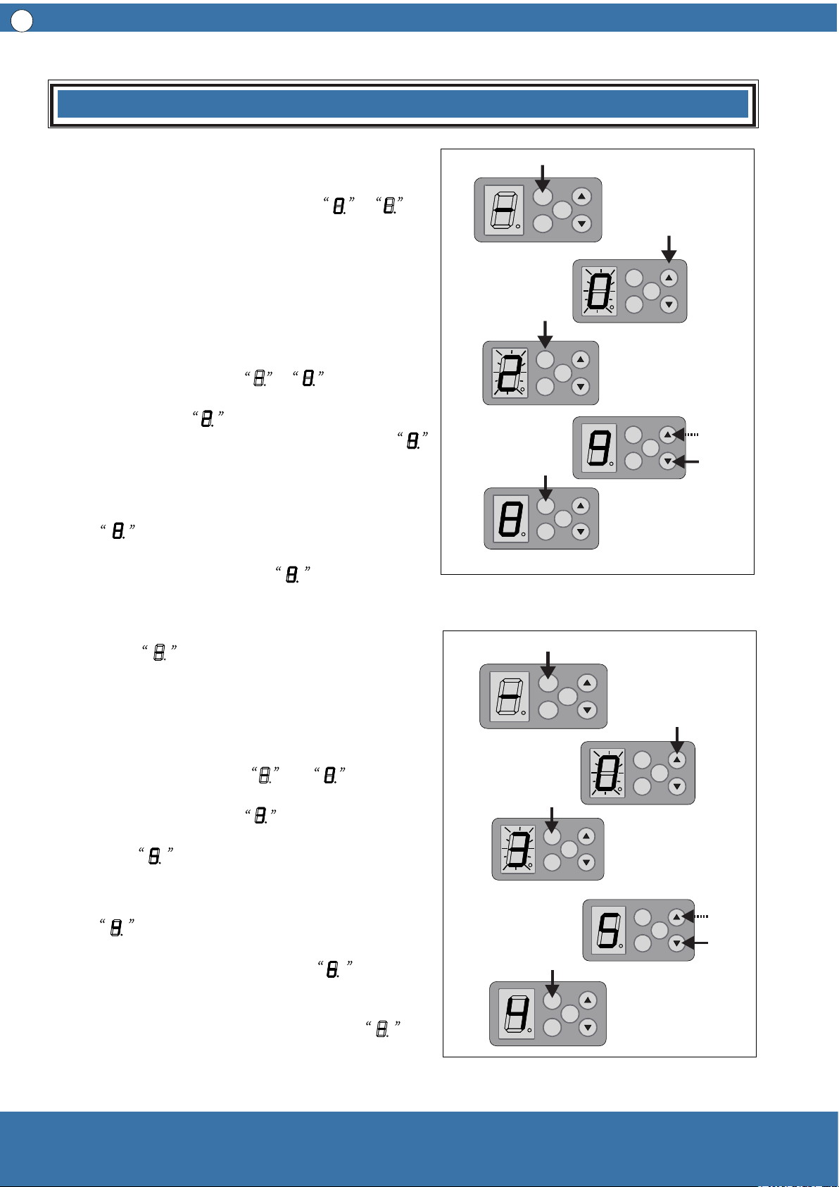
7 Set Operating Force
7.1 Set force for opening door operation ( class
1-9, see picture 10)
7.1.1 Press SET for four seconds, the digital
display tube changes from to and flickers;
then release, then press (▲ ) twice, the digital
display tube shows and flickers; at this moment
press SET once, the digital display tube shows ,
which means opening door operation force Class 9
(Factory Default).
7.1.2 Press (▼) once,the digital display tube
shows , which means lowering one class of
the force for opening door operation. Press (▲ )
the digital display tube shows , which
indicates increase one class of the force for
opening door operation. After setting the proper
class, press SET once again, the digital display
tube shows , and store new setting value
and then return to standby mode.
7.2 Set force for closing door operation ( Class
1—9, see picture 11)
7.2.1 Press SET for four seconds, the digital
display tube changes from to and
flickers, then release. Press (▲ ) three times, the
digital display tube shows and flickers, at this
moment press SET one time, the digital display
tube shows , which means closing door
operation force class 5 ( Factory Default).
7.2.2 Press ( ▼ ) one time, the digital display tube
shows , which means the door closing
operation force decreases one class; if press (▲ )
once, the digital display tube shows , this
means the door closing operation force increases
one class. After setting the proper class, press SET
once again, the digital display tube shows
,and store new setting value and then return to
standby mode.
8
SET
CO DE
OSC
SET
CO DE
OSC
SET
CO DE
OSC
SET
CO DE
OSC
SET
CO DE
OSC
SET
CO DE
OSC
SET
CO DE
OSC
SET
CO DE
OSC
SET
CO DE
OSC
SET
CO DE
OSC
Installation
Picture 10
Picture 11
Loading ...
Loading ...
Loading ...