Rolling Door Opener
Installation Instruction and User Manual
Automatic Obstacle Detection
Photo Beam Protection System
Remote Control Hopping Code
Electronic Travel
Soft Start Soft Stop
Automatic Close

MENU
1.Safety Precautions
2.Feature Introduction
3.Operation
4.Package List
5.Installation Sequence
6.Main Technical Specifications
7.Common malfunction and
Maintenance Methods.

Please read the following safety precautions carefully
Please read the following safety precautions
carefully
For much protection, it is strongly
recommended to use photo beam sensor
devices, only with a bit extra cost.
While operating the rolling door opener, always
keep the moving door in sight, and ensure that
nobody, no vehicle below the moving door.
Ignorance of this warning, severe personal
injury or equipment damage may happen.
Please do not operate the opener while a kid or
someone standing by the door. During the
process of operating the opener, in the case of
a kid nearby, the kids should be taken after by
his/her supervisor. Ignorance of this warning,
severe personal injury or equipment damage
may happen.
Children are not allowed to operate the door
opener in case of sever personal injury.
Make sure automatic obstacle detection
function performs well. Please test and set this
function according to the instructions strictly,
and conduct a regular test. If needed,
necessary adjustments should be made.
In the case that people, car or other objectives
below the rolling door, please do not pull the
clutch and operate manually.
In the case of installing wall switch or wall
transmitter, the location of wall switch or wall
transmitter should be beyond the reach of
children.
The rolling door must be well balanced. In the
case that sticking or bending, it is required to
ask qualified installation workers to check and
repair. Do not repair the door or the door opener
arbitrarily, since that there is powerful spring
inside the door, which may cause physical
injury and property loss.
Before installation of door opener, please
remove or unlock the rolling door and
mechanical devices.
The power supply for the rolling door
opener must be connected to standard
220V socket by professionals, and with
sound grounding.
The power must be cut off whenever
mending the opener or opening its cover.
The door opener should be mended by
professionals.
Hands and loose clothes are prohibited
approaching the door or door opener no
matter when.
In the case of automatic closing mode, the
photoelectric protection device must be
installed correctly. The photoelectric
protection device must be tested regularly.
While using the automatic closing function,
the above safety code should be obeyed
strictly.
In case that the door can rebound while
encountering obstacles to open mode, it
should be ensured the obstacle reverse
function be adjusted properly during the
installation of door opener. The debugging
of obstacle reverse must be carried out
repeatedly, if necessary, adjustments may
be made.
Make sure that the rolling garage door is
completely open before entering and
exiting.
Make sure the rolling garage door is
completely closed while leaving.

Features
ERDO are endowed with quite a few new
features. The components and materials used in
the control board are of the latest technology and
best quality. Following are the main features:
Easy Operation
Press the buttons of the handheld transmitter of
rolling door opener, the door will open or close
automatically. While the door is closing, simply
press the button, then the door will stop moving
down and open reversely. When opening, simply
press the button, then the door will stop moving.
Also, the above function can be achieved by
wall-mounted transmitter or wall switch (optional)
or the button on the cap of main control board.
Encryption Coding
Every time the remote control transmitter works,
the encryption coding will change once. The
possible password combination can be as much
as 4.29 billion, which enhances security
tremendously and makes “code-pirating”
impossible.
Intelligent Barrier Detection System
While the door is doing a closing cycle and hitting
an obstacle or be restricted in some manner, the
door can reverse automatically. Likewise, while
the door is opening and encountering an
obstacle, the door will close automatically. The
force of resistance should be adjusted via the
potentiometer of the main control board during
the initial installation. The force of resistance
should be checked at least once monthly, more
details please refer to installation instructions.
Security Code Storage of Transmitter
The latest advanced technology is applied in
encryption coding stored in transmitter. Up to 30
different code of transmitter can be stored. To
store any new code, simply press the CODE
button on the opener and press the transmitter
button twice, the transmitter code will be stored
immediately. The code can be deleted at any
time.
Automatic Courtesy Lights
The courtesy light on the Opener turns on
automatically whenever the door is activated to
do an opening or a closing cycle. When the
door stops moving, the courtesy light will stay
on for approximately three minutes then turns
off automatically.
Automatic Closing Mode
The Opener can be programmed to automatic
closing mode. The function of automatic delay
closing can be opted via the jumper on the
opener. I f this mode is selected, a photo beam
sensor must be installed.
Multiple Protection
Overtime protection; Low voltage protection;
Rotating speed fluctuation protection.
Manual Operation
The Opener is equipped with a manual
disengaging system. I f the power to the
Opener is cease for some reason, the door can
be shifted to manual mode by pulling down
string handle, in this situation manual open and
close is allowed. When the power is restored,
pull down the string handle then the opener is
back to the automatic mode.(The above
situation is suitable for single clutch-ERD1007;
if ERD1006—double clutches, pulling down the
red string for manual operation, pulling down
the green one for automatic operation mode).
Soft Start Soft Stop
This function can abate the impact on the door
caused by opening and closing the door
effectively.
Photo Beam Sensor(optional)
The Opener has an input for photo beam
sensor , which is to be connected for extra
safety protection. The photo beam sensor must
be installed if auto closing mode is chosen.

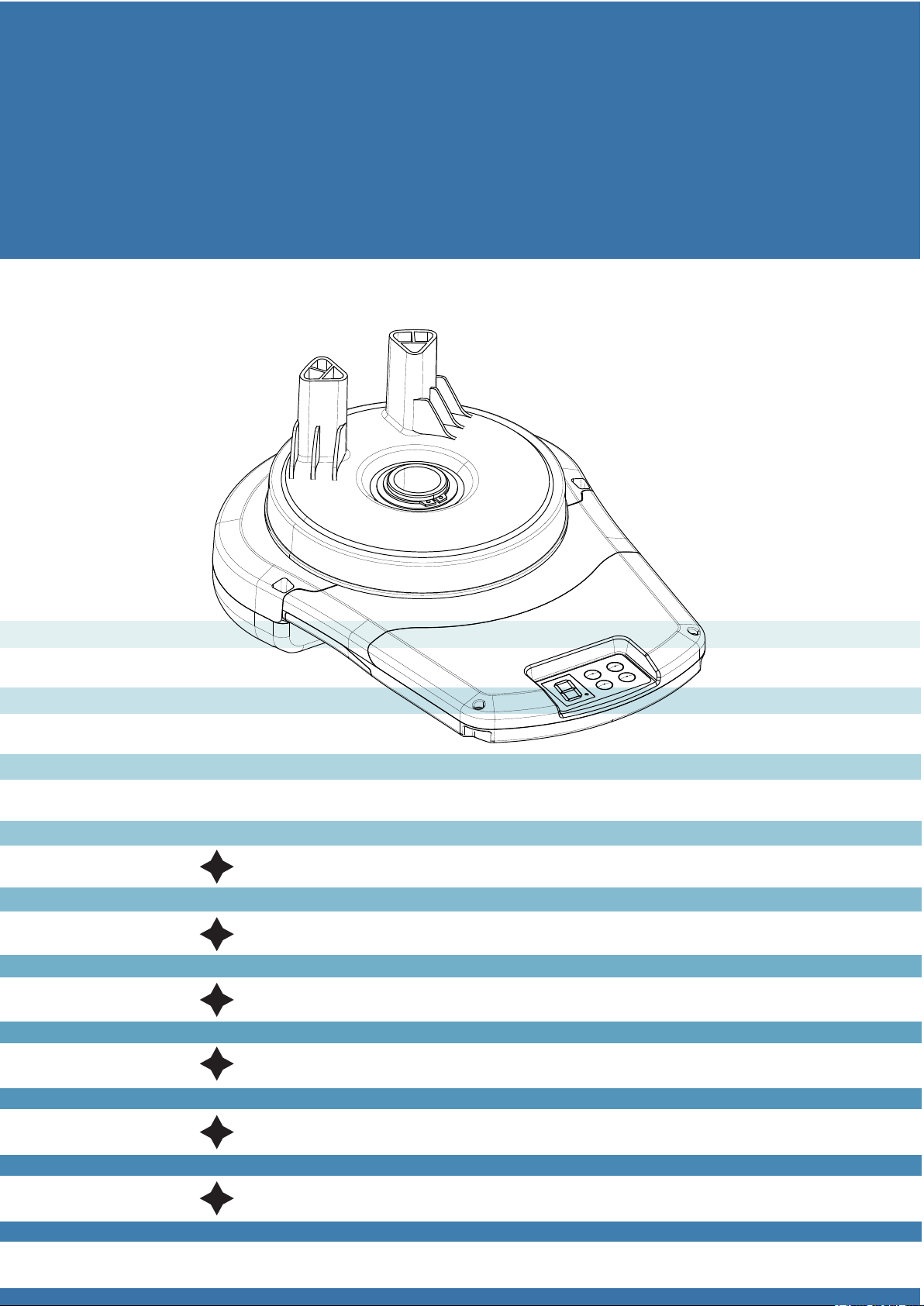
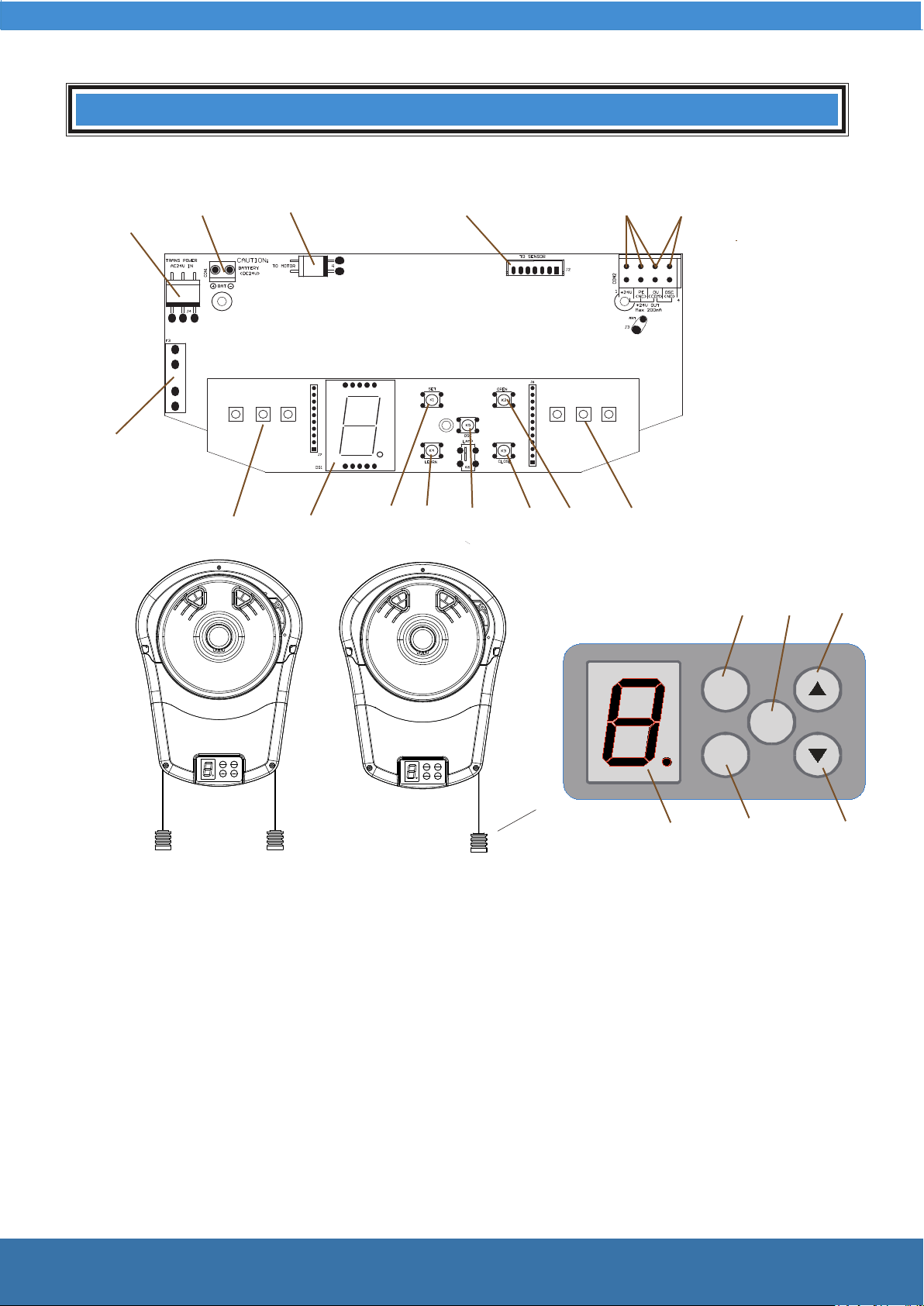
Definition of Control Board
1 Function Setting Button (Set)
During installation, please set the upper and
lower limit, left and right installation, operating
power and auto closing time.
2 Remote control learn button (Code)
Add or delete code of transmitter.
3 Increase (Open) Button (▲ )
During installation,please set the button value
be Increase or Open.
4 Decrease (Close) Button (▼ )
During installation, please set the button value
Decrease or Close.
5 Open/Stop/Close Button (OSC)
The opener operates in the cycle of
Open-----Stop--------Close-----Stop.
6 Digital Display Menu
During the installation and using, the digital menu
displays current value and status.
7 Courtesy Light
Illumination and Fault Indicator.
8 Interface to Outside Wall Switch
This interface is available for wall switch or other
control devices, the opener operates in the
manner of Open-----Stop----Close----Stop.
9 Connector for Photo Beam Sensor
DC 24V Normally Closed Photo Beam Sensor
can be connected to this connector.
10 Input for Encoder Signal
To connect the inside encoder.
11 Motor Power Output
Connect to inside DC motor
12 Backup Battery Input
Can connect DC 24V back up battery.
13 Transformer Power Input
Input AC 24V transformer power.
14 24V Power Supply Fuse
T15A/250V Fuse, in the case of burning
out, please replace it with the same model.
15 Manual Clutch Handle
When power off, pull down the clutch
handle to shift to manual operation mode;
pulling down again to automatic operation
mode.
Restrictions on Use
1 In the case of power off and manual
mode is applied, OPEN/CLOSE limit should
not exceed 20cm of the learning time,
otherwise malfunction may occur when
power on.
2 When the door stays close to the top but
not limit top, press OPEN button, the door
will not open; when the door stays near the
bottom but not limit bottom, press CLOSE
button, the door will not close.
Definition of Control Board
89
35
5
1
10
6
21
7
7
4
13
14
11
12
SET
CO DE
OSC
3
4
2
6
15
1 Function setting button
2 Remote control learn button
3 Up (Open) button
4 Down (Close) button
5 Open/Close/Stop button
6 Digital display tube
7 Courtesy light
8 Interface to outside wall switch
9 Interface to outside photo beam sensor
10 Input for encoder signal
11 Output for motor power
12 Interface to outside backup battery
13 Input for transformer power
14 24V power fuse
15 Manual/Automatic clutch handle
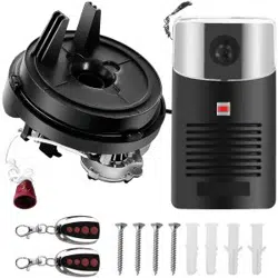
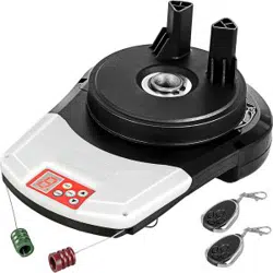
ERD1006 ERD1007
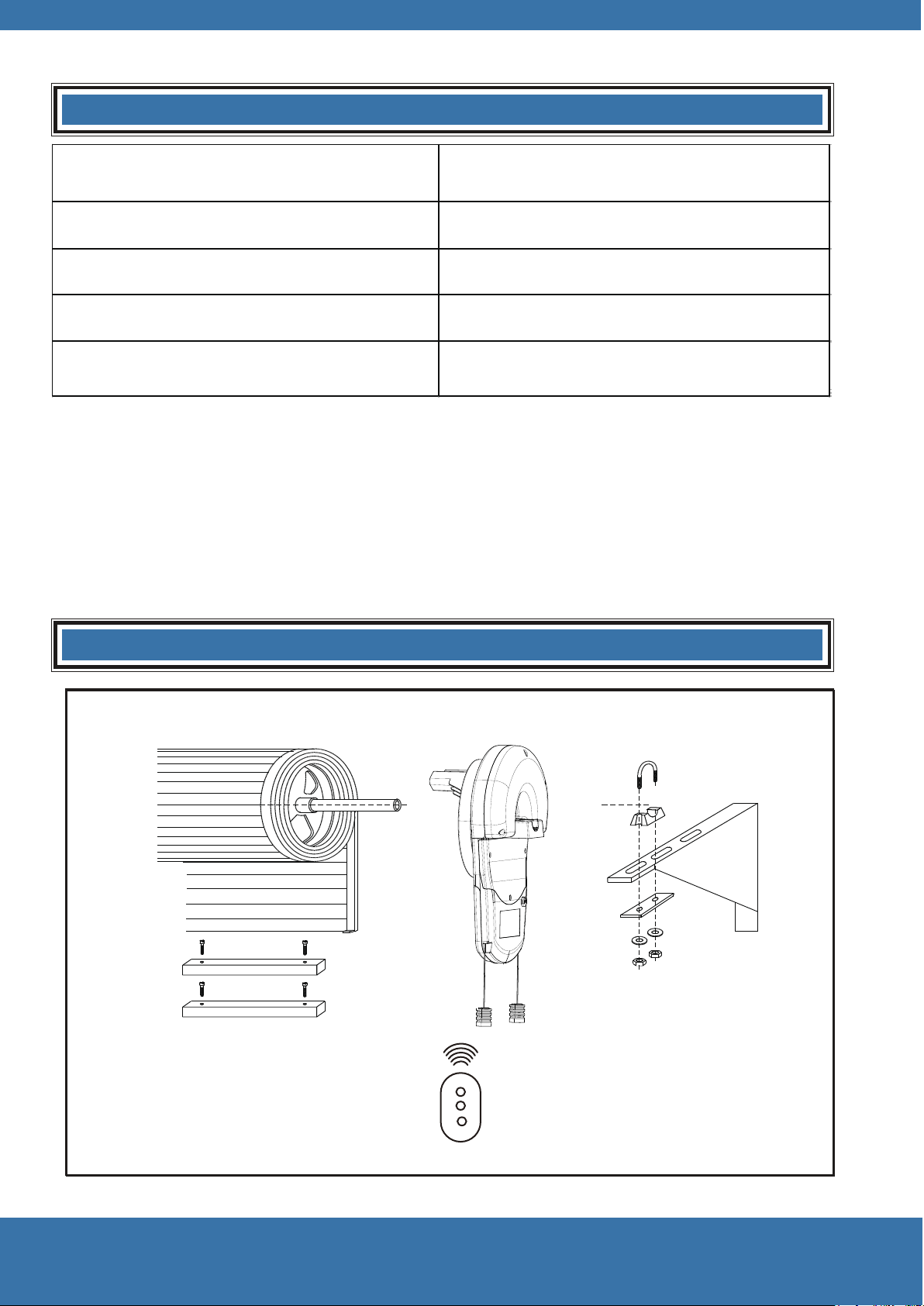
Remote controltransmitter
U Bolt
Bracket
Fixing plate
Spring Washer
Nut
Saddle gasket
Packing List
Name Quantity
Driver 1
Transmitter
Transmitter
2
U Bolt 1
Installation instructions and user manual
1
Install Sequence
Rolling door
Weight balancing bar
5
SET
CO DE
OSC
SET
CO DE
OSC
SET
CO DE
OSC
SET
CO DE
OSC
SET
CO DE
OSC
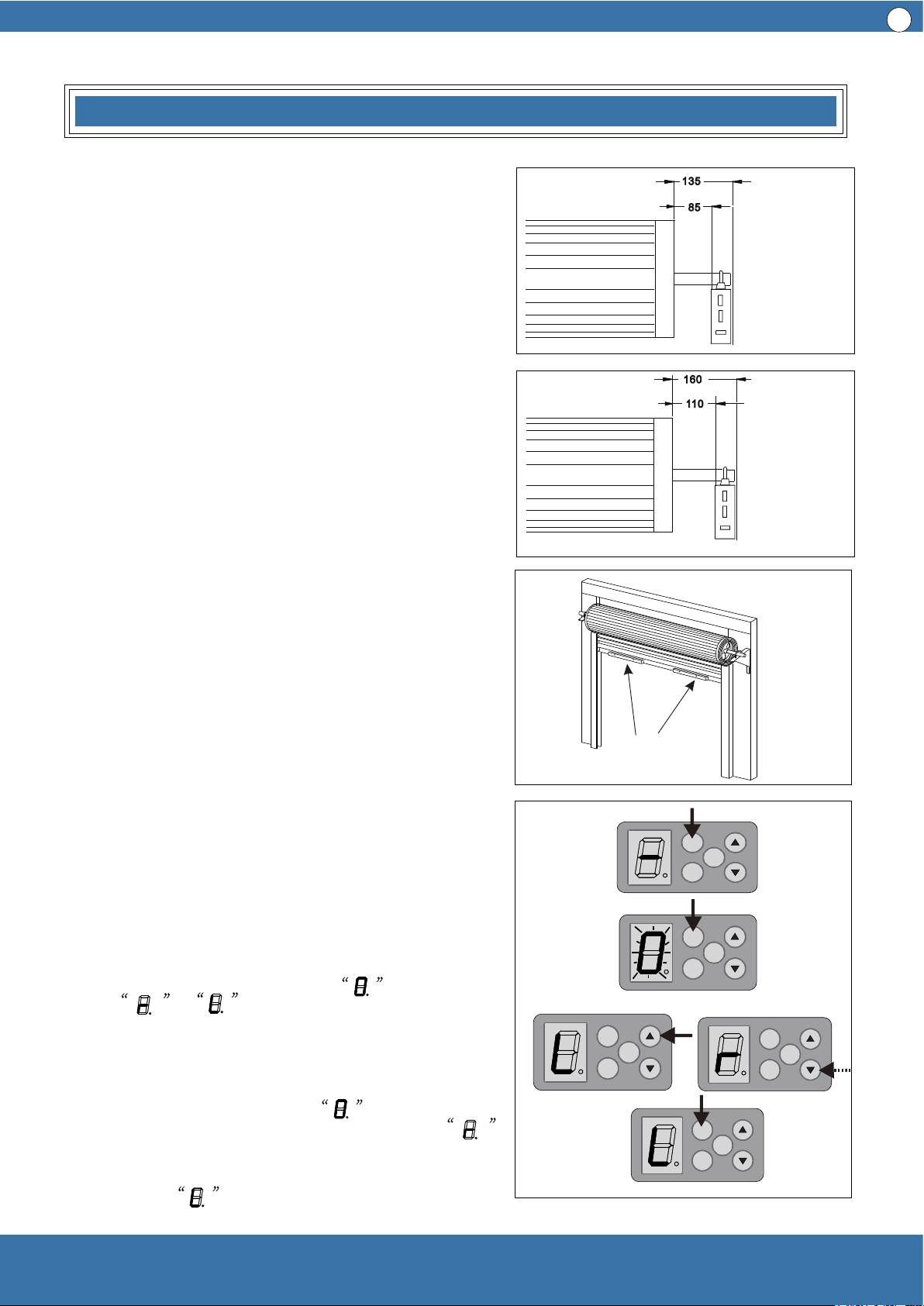
Side Room Requirements
Picture 1 shows the minimum side room that is
required: The distance between the edge of the
door curtain and the inside of the bracket should
be 85mm.; the distance between the edge of the
door curtain and the outside of the bracket
should be 135mm.
Picture 2 demonstrates the recommended side
room: The distance between the edge of the
door curtain and the inside of the bracket should
be more than 110mm; the distance between the
edge of the door curtain and the outside of the
bracket should be more than 160mm.
Picture 1
Picture 2
Picture 3
Picture 4
weight balancing
bars
Minimum side distance
Recommended side
distance
1 Check the door carefully
Before the installation of door opener, please check
the door opener carefully, and ensure the rolling
door is well balanced and in a good condition.
Therefore, the door can move smoothly in the
guide rail and can stay at around 90cm—120cm
above the ground. The force of door lifting or
downing should not over 20kg.
2 Fixing the door weight balancing bars
Move the door manually to half open position, and
place the weight balancing bars equally apart on
the door bottom, then fix them with the fasteners
provided . (see picture 3 ) Check the door again, if
the door moves heavily in the guide rail, it may
require extra tension to be added to the door
springs. In this case , please refer to the door
installation instructions from door manufacturer on
how to adjust the door spring.
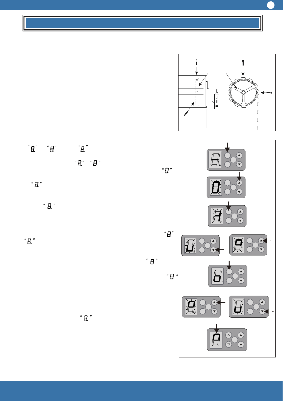
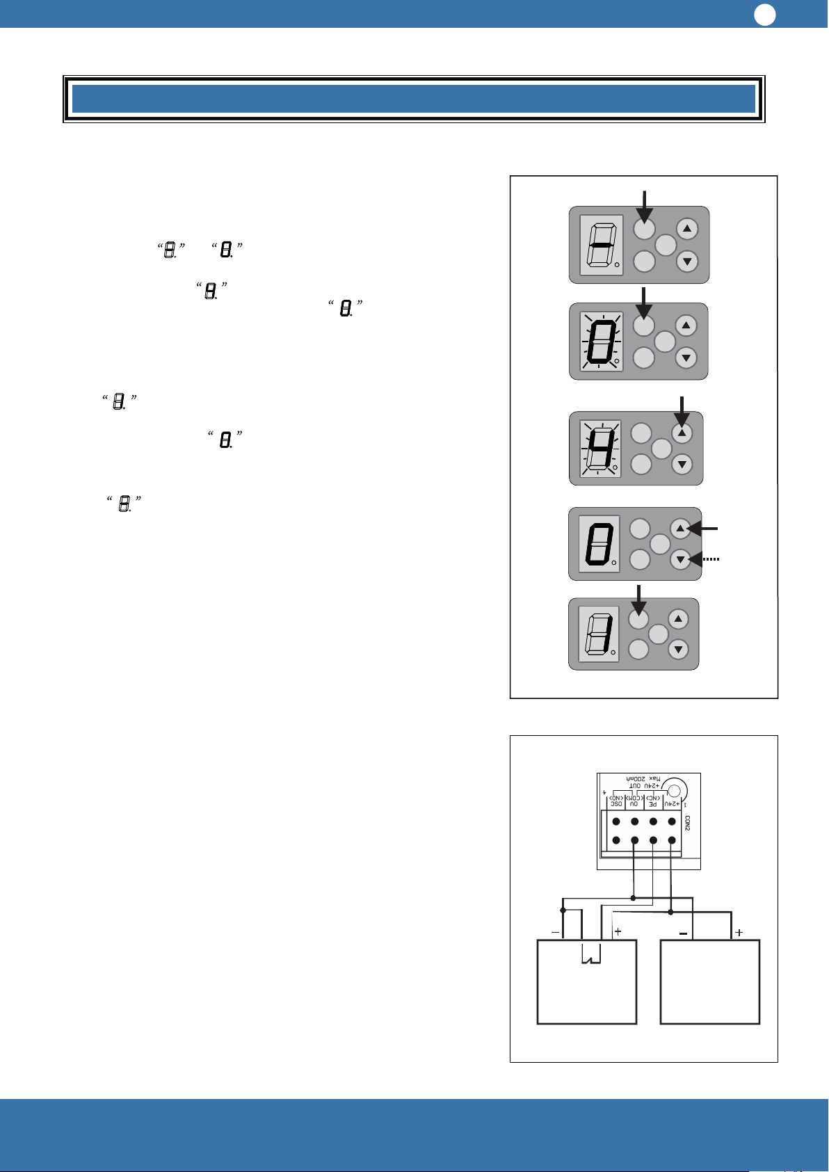
3 Door opener on the right or left
The ready opener is set to be install on the right
side, in the case of left side installation, please
reset the function setting button
from to
Operating as follows, see picture 4:
3.1 After the power is on, press the function setting
button (SET) for 4 seconds and then release, when
the digital display tube shows , press SET
button again, if the digital display tube shows ,
which indicates to right side installation, press UP
(▲) or DOWN (▼) button, when the digital display
tube shows , that means left side installation,
the press SET once more, then check and store.
Installation
Picture 5
Picture 6
Picture 7
6
Installation
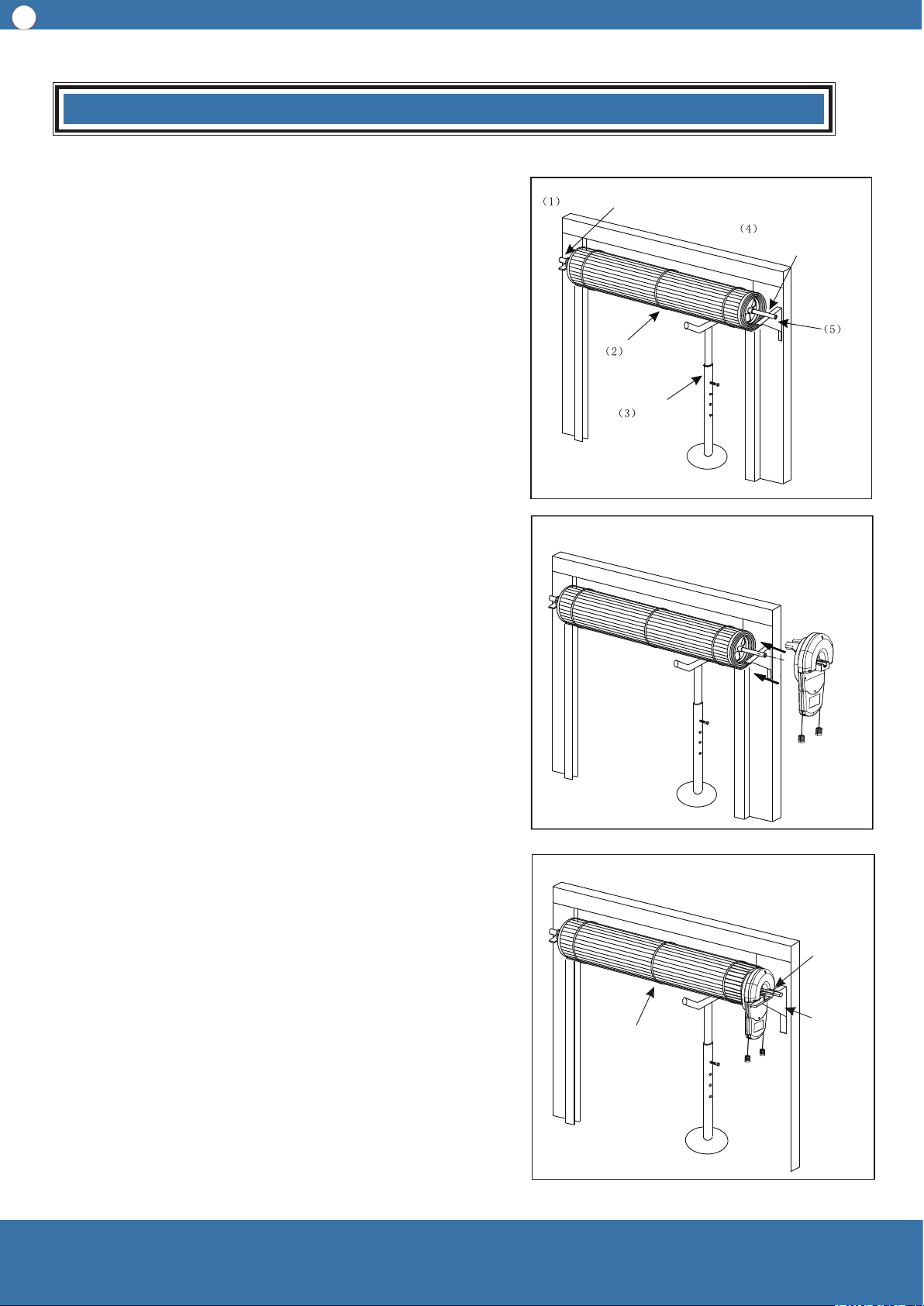
4 Door Opener Installation (Right side installation)
There are several methods of door opener installation,
following one of them is described.
First of all, make sure enough room for driver
installation, the distance between the end of the door
shaft and the wall should be 135mm at least (Attention:
this method only suitable for right side installation). For
specific installation, please refer to picture 5, picture 6,
picture.
4.1 Check carefully to see whether the U bolt on the left
side is tightly fixed on the door shaft.
4.2 Lift up the door, tie up the door firmly with a rope in
middle position.
4.3 Use support to sustain the right part of the door
curtain. (Attention: Something soft should be padded
under the support in case of door surface damage.)
Warning: During installation, children are forbidden to be
around, if ignore this warning, severe personal injury or
property loss may be caused.
4.4 Check if step 3 is finished, then release the U bolt
on the right side of the door and take it away carefully.
4.5 After right the door support removed from the wall,
please make sure that the support of the door is safe
and reliable.
4.6 Take out the opener from the package, manually
turn the forks on the opener to make the gear spin, if the
gear do not spin, it is considered as auto mode. At this
time, please draw the clutch handle (if ERD1006 draw
red clutch) manually and softly to take part the driving
gear and the motor to shift to manual operation mode,
in this case the gear can spin freely.
4.7 Push the opener along the door shaft to plastic
plate, and make sure that the double forks of the gear is
in the narrowest spoke and stretch into the plastic plate.
4.8 Reinstall the right side support, if special case, the
support frame should be relocated, and retighten the U
bolt, remove the support below the door and the
bundled rope.
4.9 Move the door up and down with the hands to see
if the door operates well. The door should move
smoothly and can not be touched.
Make sure that the U bolt is fixed firmly
Rope
Shear the rope
Remove the support
Reinstall
right side
support
frame
Refix the
U bolt
Support
Remove the U bolt
Remove the
right side
support frame
If the gear of
the driver can
not spin, please
draw the clutch
handle
6.1.1 Put on the power plug, the digital display tube change
from to . Finally , see picture 9.
6.1.2 Press SET button for 4 seconds, when the display on
digital display tube from to and flicker, then hands off,
press the UP (▲) button once, the digital display tube turn
and flicker, then press SET one time and the digital display tube
shows , which means setting the proper position for door
closing.
6.1.3 Press CLOSE (▼) uninterrupted and the digital display
tube shows and flicker, meanwhile the door is closing.
(When hands off, the door will stop closing; if the door opens at
this time, that means the wrong setting of left side installation
and right side installation. In this case, the opener should be
power off then power on again. Please refer to 3.1 and turn
into . After the door is totally closed, release
CLOSE (▼), if
the door is not in proper position, please press
CLOSE (▼) or
OPEN (▲) once, to make the door close in the ideal place, then
press SET once again, the digital display tube turns , which
means to set the proper position after door totally opened.
6.1.4 Press (▲) uninterrupted, the digital display tube shows ,
then start to flicker, at the same time the door opens, when the
door is totally open, release (▲ ), if the door does not stop at an
ideal position, please press (▲ ) or (▼ ) once to make the door
stay at the ideal place. Repress SET once, the door will close
immediately and stop at the right totally closed position. Finally,
digital display tube shows and finish door travel position
settings.
Attention: After the ideal place for door closing and before
setting the ideal position for door opening, the position for
opening door ( height of opening door) stay should be within
1---3 meters; if the opening door height is beyond 1—3 meters,
when you press SET, the door will not close automatically, at
this time the courtesy light keep flickering for a while to show
that the wrong position and new settings should be done.
Picture 8
Picture 9
Installation
Drum-shaped
plastic wheel
7
SET
CO DE
OSC
SET
CO DE
OSC
SET
CO DE
OSC
SET
CO DE
OSC
SET
CO DE
OSC
SET
CO DE
OSC
SET
CO DE
OSC
SET
CO DE
OSC
SET
CO DE
OSC
5 Please fix the door curtain on the drum-shape plastic
wheel
The door curtain must be fixed firmly on the drum-shape plastic
wheel.
1 Close the door completely, make marks on the both sides
towards the plastic wheel.
2 Please find the marks when door is slightly open, use two
self-tapping screws on every side of the door curtain on plastic
wheel. Attention: the position of the two screws should be in the
90 degree direction, see picture 8.
6 Set up and down travel position
6.1 In the case of right side installation: please move the door to
the middle position manually, and draw the clutch handle (if
ERD1006 draw the green clutch handle) once to make sure
the door opener is in auto mode.
4 Door Opener Installation (Right side installation)
There are several methods of door opener installation,
following one of them is described.
First of all, make sure enough room for driver
installation, the distance between the end of the door
shaft and the wall should be 135mm at least (Attention:
this method only suitable for right side installation). For
specific installation, please refer to picture 5, picture 6,
picture.
4.1 Check carefully to see whether the U bolt on the left
side is tightly fixed on the door shaft.
4.2 Lift up the door, tie up the door firmly with a rope in
middle position.
4.3 Use support to sustain the right part of the door
curtain. (Attention: Something soft should be padded
under the support in case of door surface damage.)
Warning: During installation, children are forbidden to be
around, if ignore this warning, severe personal injury or
property loss may be caused.
4.4 Check if step 3 is finished, then release the U bolt
on the right side of the door and take it away carefully.
4.5 After right the door support removed from the wall,
please make sure that the support of the door is safe
and reliable.
4.6 Take out the opener from the package, manually
turn the forks on the opener to make the gear spin, if the
gear do not spin, it is considered as auto mode. At this
time, please draw the clutch handle (if ERD1006 draw
red clutch) manually and softly to take part the driving
gear and the motor to shift to manual operation mode,
in this case the gear can spin freely.
4.7 Push the opener along the door shaft to plastic
plate, and make sure that the double forks of the gear is
in the narrowest spoke and stretch into the plastic plate.
4.8 Reinstall the right side support, if special case, the
support frame should be relocated, and retighten the U
bolt, remove the support below the door and the
bundled rope.
4.9 Move the door up and down with the hands to see
if the door operates well. The door should move
smoothly and can not be touched.
6.2 Setting of left side installation: the same as
the right side installation, please refer to 6.1.
6.2.1 Please refer to 3.1 and change to .
Hereafter all the setting are the same as right side
installation, please refer to 6.1.
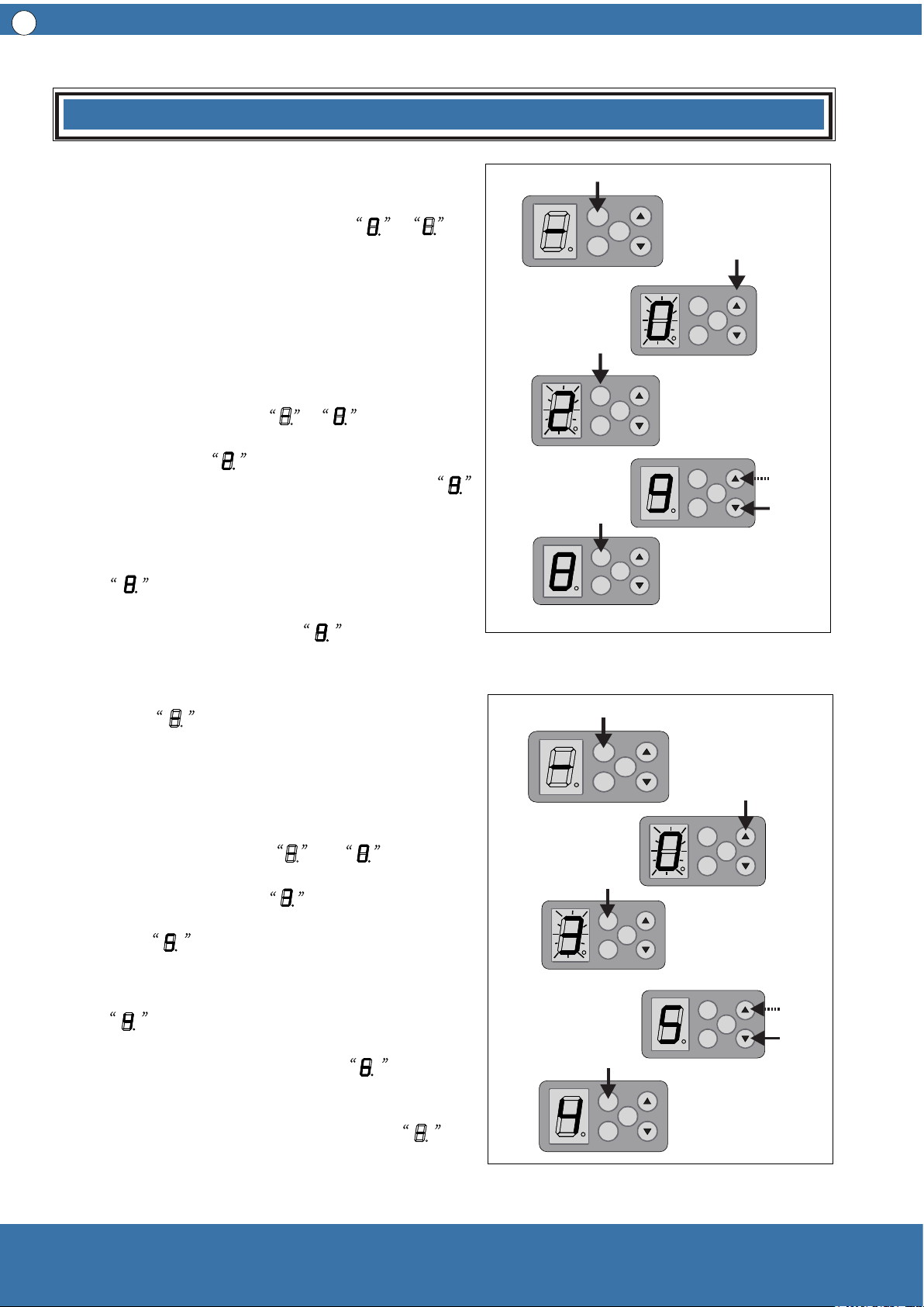
7 Set Operating Force
7.1 Set force for opening door operation ( class
1-9, see picture 10)
7.1.1 Press SET for four seconds, the digital
display tube changes from to and flickers;
then release, then press (▲ ) twice, the digital
display tube shows and flickers; at this moment
press SET once, the digital display tube shows ,
which means opening door operation force Class 9
(Factory Default).
7.1.2 Press (▼) once,the digital display tube
shows , which means lowering one class of
the force for opening door operation. Press (▲ )
the digital display tube shows , which
indicates increase one class of the force for
opening door operation. After setting the proper
class, press SET once again, the digital display
tube shows , and store new setting value
and then return to standby mode.
7.2 Set force for closing door operation ( Class
1—9, see picture 11)
7.2.1 Press SET for four seconds, the digital
display tube changes from to and
flickers, then release. Press (▲ ) three times, the
digital display tube shows and flickers, at this
moment press SET one time, the digital display
tube shows , which means closing door
operation force class 5 ( Factory Default).
7.2.2 Press ( ▼ ) one time, the digital display tube
shows , which means the door closing
operation force decreases one class; if press (▲ )
once, the digital display tube shows , this
means the door closing operation force increases
one class. After setting the proper class, press SET
once again, the digital display tube shows
,and store new setting value and then return to
standby mode.
8
SET
CO DE
OSC
SET
CO DE
OSC
SET
CO DE
OSC
SET
CO DE
OSC
SET
CO DE
OSC
SET
CO DE
OSC
SET
CO DE
OSC
SET
CO DE
OSC
SET
CO DE
OSC
SET
CO DE
OSC
Installation
Picture 10
Picture 11
Picture 13
Picture 12
SET
CO DE
OSC
block
9
close
open
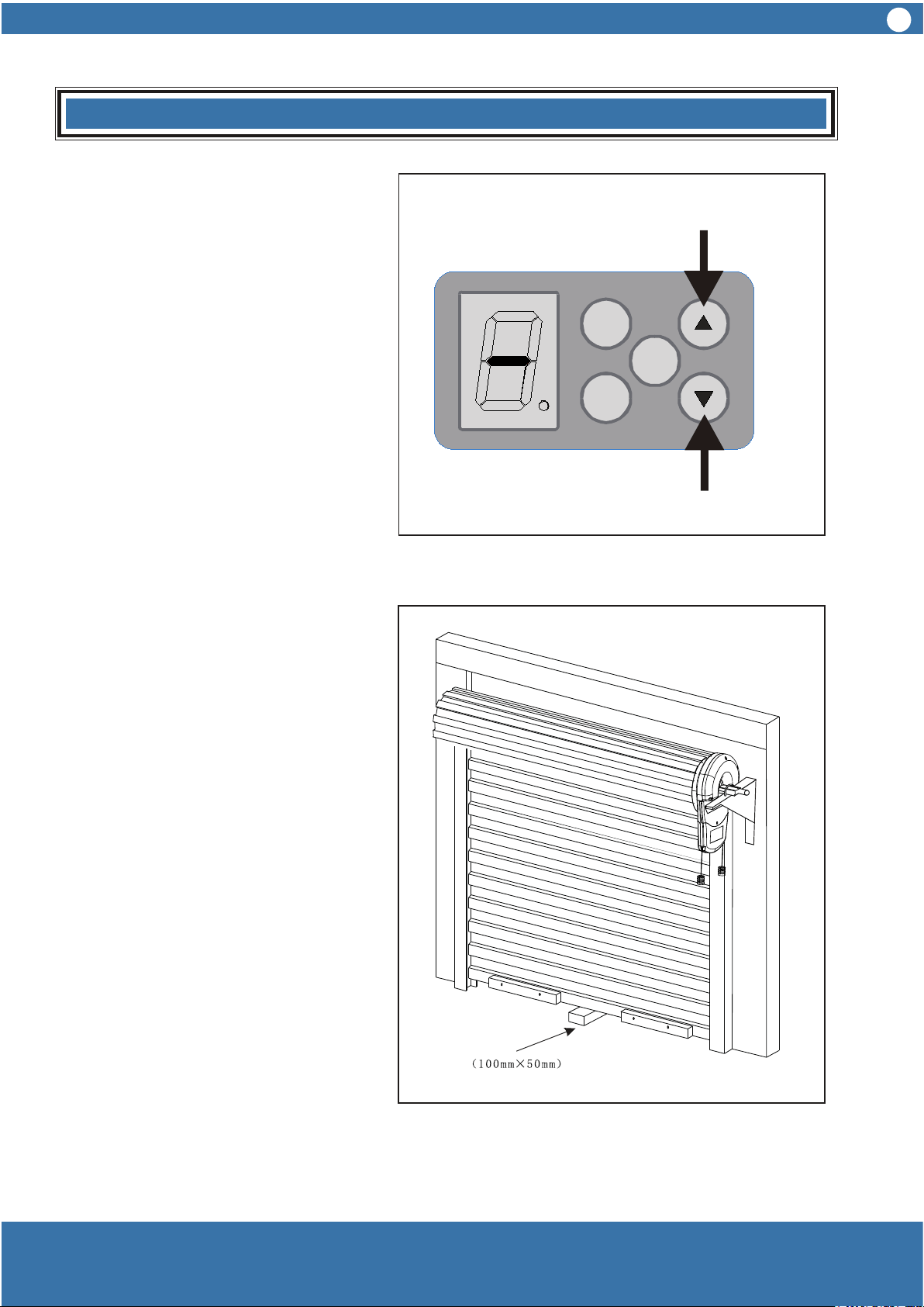
Installation
Checking door closing force
1 Press OPEN button (▲ ) until door up
to the highest position, see picture 12.
2 Place a 100mm x 50mm block below
the door, see picture 13.
3 Press CLOSE (▼ ) to close the door
until the door hits the block and begins
moving reversely until the door is totally
open.
Checking door opening force
1 Remove the block, press CLOSE (▼ )
until the door is completely closed, see
picture 12.
2 Press OPEN (▲ ) to open the door
until the door moves to midway, use
hands to firmly grasp the door bottom,
the door should stop moving up.
In the case that the door does not
backtrack easily when closing, or in the
case that the door stop hardly when
opening, both these two cases
demonstrates that the force is not well
adjusted. Then please follow 7.1, 7.2,
7.3, 7.4 to readjust.
Warning:
When door is closing, if there is
something wrong with torque testing
system, please adjust and retest until
everything meets requirements that
the door can be operated.
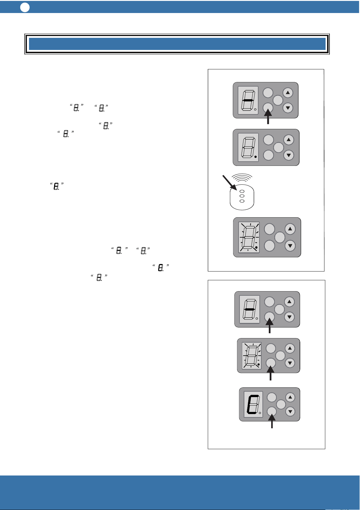
8 Setting of Remote Control Transmitter
8.1 Learning a transmitter, see picture 14.
8.1.1 Press CODE once, the digital display tube
changes from to and enter into the learning
condition, then press one of the buttons twice, and
the digital display tube flickers quickly then
turns into , and the code is learned.
Press the CODE to check if it can control the relevant
door operation. This learning method can be applied
into other transmitter learning.
Attention: if press CODE, the digital display tube
shows , which means the opener has stored 30
transmitters, no new transmitter can be learned any
more.
8.2 Delete of remote control transmitters
8.2.1 Press CODE uninterrupted until the digital
display tube changes from to and flickers,
then enter into delete transmitter condition. After eight
seconds, the digital display tube shows and
flickers, then shows , at this moment release
the button and finish deleting transmitters. If release
CODE within 8 seconds, itc comes into the learning
condition.
9 Courtesy Light Auto Turn off Time
the auto turn off time is three minutes
Picture 14
Picture 15
A U TO M A TIC C O N TR O L
NU-TECH
10
A U TO M A TIC C O N TR O L
NU-TECH
10
SET
CO DE
OSC
SET
CO DE
OSC
SET
CO DE
OSC
SET
CO DE
OSC
SET
CO DE
OSC
SET
CO DE
OSC
SET
CO DE
OSC
SET
CO DE
OSC
SET
CO DE
OSC
SET
CO DE
OSC
SET
CO DE
OSC
SET
CO DE
OSC
Installation
10 Auto Close Set
10.1 Auto close time setting (class 0, 1—9, see picture 17)
10.1.1 Press SET for four seconds, the digital display tube
changes from to and flickers, at this moment
release SET button. Press (▲ ) four times, the digital
display tube shows and flickers, at this moment press
SET once, digital display tube shows , which indicates
auto closing class 0 ( Factory default, in other words, auto
close function is closed.)
10.1.2 Press (▲ ) once, the digital display tube
shows, which indicates auto close time increases one
class ( one class means one minute); if press (▼ ) once, the
digital display shows , which means the auto close
time decreases one class; After setting the proper class,
please press SET once again. The digital display tube
shows , restore new setting value, and then return to
standby mode.
Only when the door open to the limit and auto close time is
set, the auto close timer begins counting. If Photo beam
sensor is blocked, the door will keep open. The door will
reopen when obstructed or the photo beam sensor is
blocked during closed.
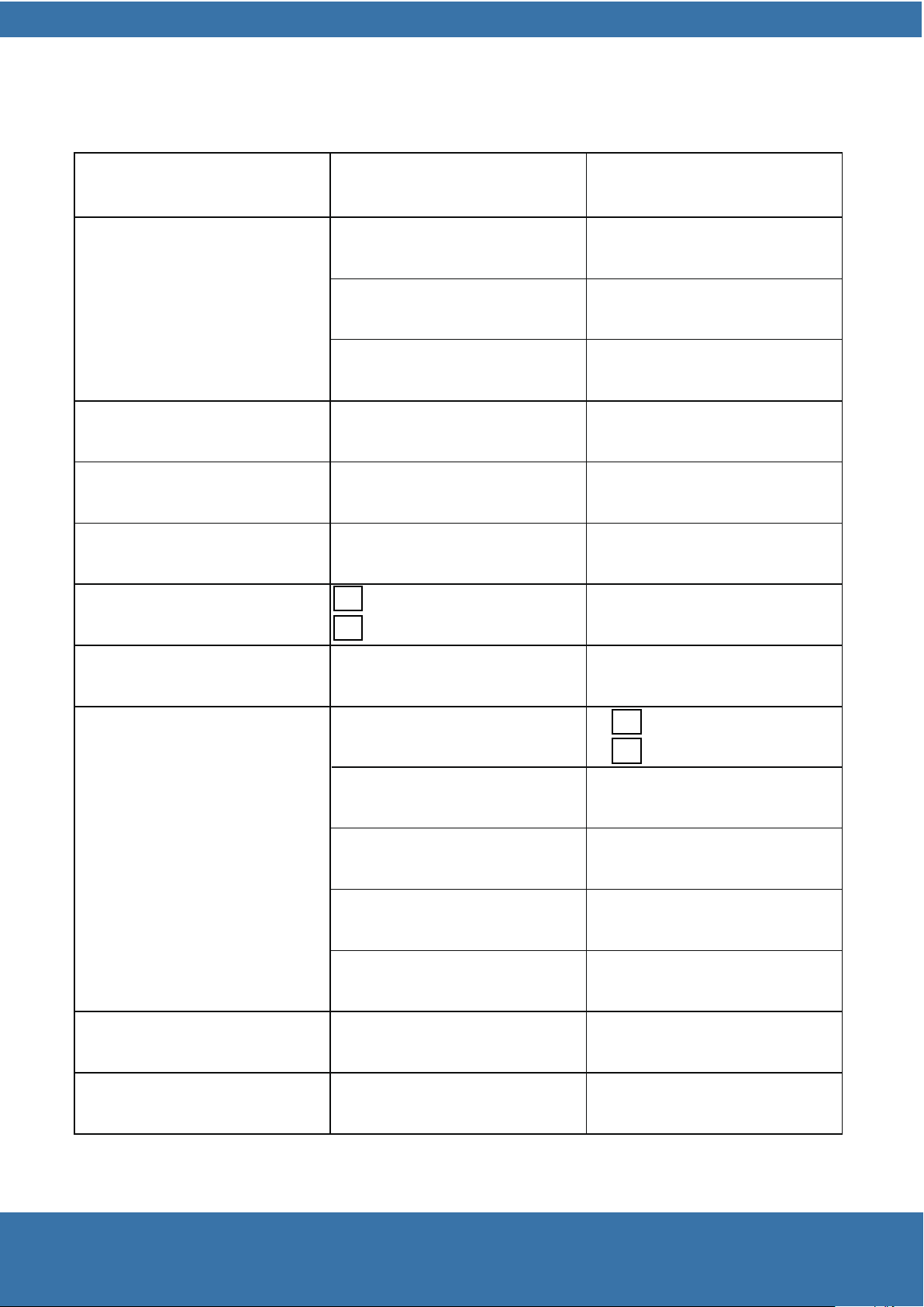
11 Photo Beam Sensor ( Optional)
11.1 A normal closed photo beam sensor is recommended
to install at a suitable place beside the door and connect the
wires to CON2 PCB board. ( See picture 18)
Anything about the connection of circuit diagram photo beam
sensor, please refer to of the photo beam sensor manual.
Warning: When use auto close and photo beam sensor,
there should not be obstacles or people around the
door. The installation position and method should be
proper, or the protection function will not be effective.
Picture 16
Picture 17
Installation
SET
CO DE
OSC
SET
CO DE
OSC
SET
CO DE
OSC
SET
CO DE
OSC
SET
CO DE
OSC
Receiving
end
Transmitting
end
O U T
C O M
11
TECHNICAL SPECIFICATIONS
INPUT VOLTAGE
TRANSFORMER
PRIMARY VOLTAGE
SECONDARY VOLTAGE
CONTROLLER VOLTAGE
220-240VAC 50HZ
220V/240V AC
24V AC 100VA
24VDC
RATED LOAD
Opening /Clsoing limits travel
800N
60secs
6 turns of door drum wheel
Opening /Clsoing run time
Receiver type
Transmitter
30 transmitter codes
Receiver code storage capacity
Coding Type
NO of code combinations
Code generation
Battery voltage
Direct current
Motor type
Globe
Frequency
Code Hopping
over 4.29 billion random code
Non-linear encryption
algorithm
12V
LED Lighting
Permanent magnet
24VDC
UHF 433.92MHZ ,AM Receiver
UHF 433.22MHZ ,AM Receiver
433.92MHZ
433.22MHZ

NU-TECH
SYMPTOMS POSSIBLE CAUSE SOLUTION
Door do not operate
Power do not turn on Turn on the power
Door do not operate
Door is obstructed Remove obstruction
Door is locked or motor is
stuck
Open the lock
stuck
Check the motor
Door is obstructed and
fails to upward
Operating force is too
strong
Closing force is too strong,
decrease the door closing
operation force( refer to
7.2)
Door opens automatically
when door is closing
Door deformation or rail
tracks narrow because of
extreme weather (frozen,
windy)
Closing force is too weak
, increase the door closing
operation force (refer to
7.2)
Door is obstructed Remove the obstacles
Door operates from drive
unit but not from hand-
hold transmitter
Indicator on transmitter do
not light
Battery is not well
connected
unit but not from hand-
hold transmitter
Transmitter has not
been learnt
Refer to step 8
Driver Unit antenna is not
extended
Extend the antenna
No power in battery Replace the battery
Door stops automatically Opener is overloaded
; door is obstructed and
the spring is not elastic
Stop using the door and
door open to avoid
damage
Auto close function do not
work
Photo beam sensor is
broken or the power is off
Mend photo beam sensor
and turn on power
work
Photo beam sensor is
blocked
Remove the obstruction
Door is hindered when
closing
Closing force is too weak
, increase the door closing
operation force (refer to
7.2)
Not set the auto closing
time
Refer to installation
instruction step 11
Soft stop time too long, or
too short, or no
Do not set soft stop and
soft start
See installation instruction
step 6
Malfunctions AND SOLUTIONS

Installation
NOTES