Loading ...
Loading ...
Loading ...
Assembly Step 2 I
Install the Trolley on the T-rail
I
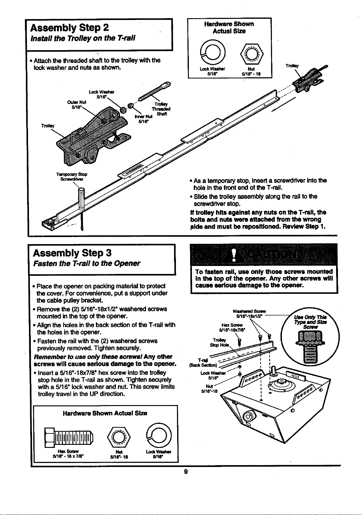
• Attach the threaded shaft to the trolley with the
lock washer and nuts as shown.
Tro,ey
LockWasher
5116"
OutorNut
T_
Thm_l
Shaft
kmerNut
5/16"
Hardware Shown
Actual Size
©©
LockWssher Nut
5/16" 5/16"- 18
Tro_y
TempormySto_
Screwdriver
• As a temporary stop, insert e screwdriver intothe
hole in the front end of the T-rail.
• Slide the Volley assembly along the rail to the
screwdriver stop.
If trolley hits against any nuts on the Trail, the
bolts and nuts were attached from the wrong
Fide and must be reposltioned. Review Step 1.
Assembly Step 3
Fasten the T-rail to the Opener
• Place the opener on packing material to protect
the cover. For convenience, put a s_upportunder
the cable pulley bracket.
• Remove the (2) 5/16"-18xl/2" washered screws
mounted in the top of the opener.
• Alignthe holes in the back section of the T-rail with
the holes in the opener.
Fasten the rail with the (2) washered screws
previously removed. Tighten securely.
:remember to use only these screwel Any other
screws will cause serious damage to the opener.
• Insert a 5/16"-18x7/8" hex screw into the trolley
stop hole in the T-rail as shown. Tighten secqrely
with a 5/16" lock washer and nut. This screw limits
trolley travel in the UP direction.
wm sony
5PI6;18xli2"
T_ 5/16"-18x7/8"
(BackSecmon)_
LockWmJ"mr--
5/16"
Nut
5/16"-18
Hardware Shown Actual Size
He_ Screw Nut LOOKWuher
5/16"- 18 x 7/8" 5/16"- 18 5/16"
9
Loading ...
Loading ...
Loading ...