Loading ...
Loading ...
Loading ...
Installation Step 10 I
Install the Safety Reversing Sensor
I
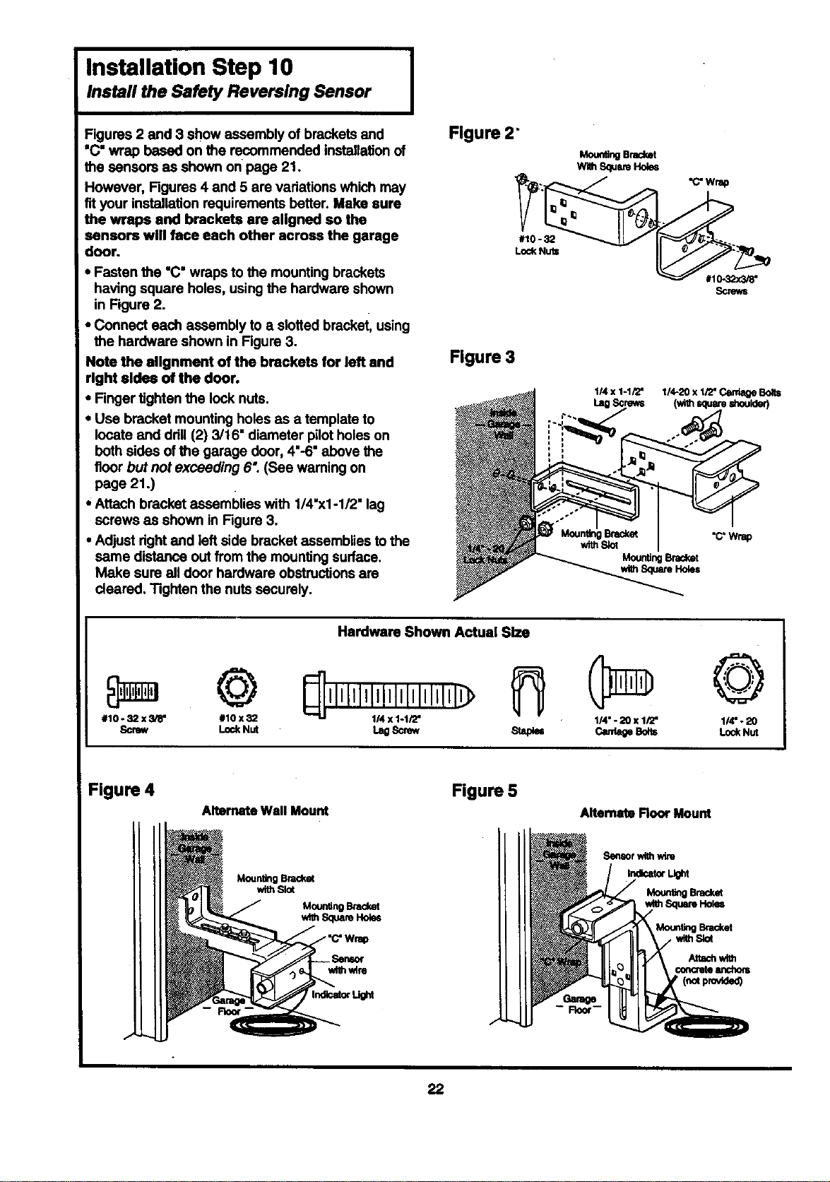
Figures 2 and 3 show assembly of brackets and
'C" wrap based on the recommended installation of
the sensors as shown on page 21.
However, Figures 4 and 5 are variations which may
fit your installation requirements better. Make sure
the wraps and brackets are aligned so the
sensors will face each other across the garage
door.
• Fasten the "C" wraps to the mounting brackets
having square holes, using the hardware shown
in Figure 2.
• Connect each assembly to a slotted bracket, using
the hardware shown in Figure 3.
Note the alignment of the brackets for left and
right aldea of the door.
• Finger tighten the lock nuts.
• Use bracket mounting holes as a template to
locate and drill (2) 3/16" diameter pilot holes on
both sides of the garage door, 4'-6" above the
floor but not exceeding 6: (See waming on
page 21 .)
• Attach bracket assemblies with 1/4"xl -1/2" lag
screws as shown in Figure 3.
• Adjust right and left side bracket assemblies to the
same distance out from the mounting surface.
Make sure all door hardware obstructions am
cleared. Tighten the nuts securely.
Figure 2"
#10 - 32
LockNUts
Figure 3
Mour_ngBracket
WithSquareHokm
1/4x 1-1/2"
LagScrews
MountingBracket
t(ithSquareHoles
"C'Wrap
©
#10.32 x3/8" #10x32
Screw LockNut
Hardware Shown Actual Size
L.0scr_ slap_
1/4"- 20 x 1/2"
©
1/4" - 20
LockNut
Figure 4
Alternate Wall Mount
Figure 5
Altemate Root Mount
MountingBracket
withSlot
Sensorwithwire
IrKrK=atorUght
Bracket
Attachwith
concruteanchom
(notpr_/Ided)
22
Loading ...
Loading ...
Loading ...