Loading ...
Loading ...
Loading ...
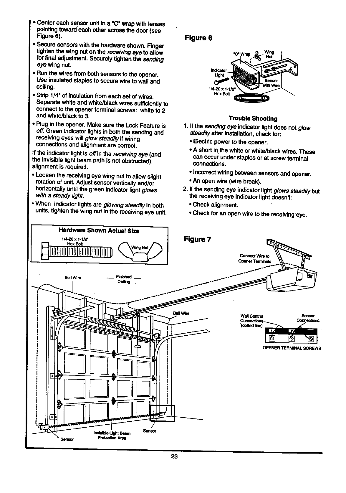
• Ce_ereachsensorunitina "C' wrap with lenses
pointingtowardeach other across the door (see
Figure 6).
• Secure sensors with the hmdware shown. Finger
tighten the wing nut on the receiving eye to al ow
for final adjustment. Securely tighten the sending
eye wing nut.
• Run the wires from both sensors to the opener.
Use insulated staples to secure wire to wall and
ceiling.
• Strip 1/4" of insulationfrom each set of wires.
Separate white and white/black wires sufficientlyto
connect to the opener terminal screws: white to 2
and white/black to 3.
• Plug in the opener. Make sure the Lock Feature is
off. Green indicator lights in boththe sending and
receiving eyes will glow steadily ifwiring
connections and alignment are correct.
If the indicator light is oflin the receiving eye (and
the invisible light beam path is not obstructed),
alignment isrequired.
• Loosen the receiving eye wing nut to allow slight
rotation of unit. Adjust sensor verticelly and/or
horizontally until the green indicator light glows
with a steady light,
• When indicator lights are glowing steadilyin both
units, tighten the wing nut in the receiving eye unit.
Figure 6
114-20x 1-1/2"
HexBen
Trouble Shooting
1. If the sending eye indicator light does not glow
steadily after installation, check for:.
• Electric power to the opener.
• A short inthe white or white/black wires. These
can occur under staples or at screw terminal
connections.
• Incorrect widng between sensors and opener.
• An open wire (wire break).
2. If the sending eye indicator light glows steadily but
the receiving eye indicator light doesn't:
• Check alignment.
• Check for an open wire to the receiving eye.
Hardware Shown Actual Size
1/_.20 x 1-1/2"
Figure 7
Connect_re to
OpenerTerminals
BellWbe
WAIl Control Sensor
OPENER TERMINALSCREWS
23
Loading ...
Loading ...
Loading ...