Loading ...
Loading ...
Loading ...
30 31-5000573 Rev. 2
ENGLISH
Electric Wiring and Applications Cont.
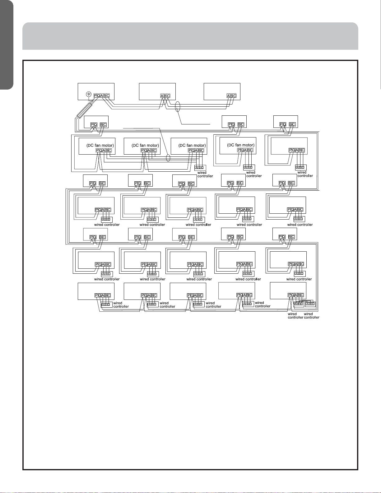
Communication Wiring Figure (Wired)
INSTALLATION INSTRUCTIONS
Outdoor 1
Indoor 1 Indoor 2 Indoor 3
Indoor 4
Indoor 5
Indoor 6
Indoor 7Indoor 8
Indoor 9Indoor 10
Indoor 11
Indoor 16 Indoor 17 Indoor 18 Indoor 19 Indoor 20
Indoor 12 Indoor 13 Indoor 14 Indoor 15
VP 1 VP 2 VP 3
VP 4VP 5
VP 6VP 7VP 8
VP 9 VP 10 VP 11 VP 12 VP 13
Outdoor 2 Outdoor 3
Communication
wire with polarity
Control wire for wired
controller with polarity
Only one end of the shield should be
connected to the earth.
IMPORTANT
• Outdoor units are in parallel through 3 polar wires. The outdoor and all VP(cooling and heating swithing device)and all
indoor units are in parallel through 2 non-polar wires.
• Each VP can be connected to 1~8 indoor units. For the wiring, please refer to the above pictur: VP1 is connected to indoor
1~3, and the capacity of all the indoor units can not be more than the VP’s. Indoor units which are not conneted to VP just
have cooling operation, and the wiring can be referred to indoor 16~20 on the above picture.
• The communication line must be hand-in-hand serial connection, not using star connection.
• When the length of the single line of communication is not sufficient, the joint connection must be pressed or solder.
• There are three connecting ways between wired control and indoor units:
A. One wired controller controls multiple units, as shown in the above figure (1~3 indoor units). The indoor unit 3 is the
wired control main unit (directly connected to the indoor unit of wired controller) and others are the wired control sub
units, 1~3 indoor units are the DC fan motor model. The wired controller is connected with the main unit and DC fan
motor models through three lines with polarity. Other indoor units and the main unit ar connected via two lines with
polarity, SW01 on the main unit is set to 0 while SW01 on other sub units are set to 1, 2, 3 and so on in turn. (Please refer
to the dip switch setting)
B. One wired controller controls one indoor unit, as shown in the above figure (indoor unit 6~19). The indoor unit and the
wired controller are connected via three lines with polarity.
C. Two wired controllers control on indoor unit, as shown in the figure (indoor unit 20). Either of the wired controllers can
be set to be the main wired control while the other is set to be the sub wired controller. The main wired controller, sub
wired controller and indoor units are connected via three lines with polarity.
Loading ...
Loading ...
Loading ...