Loading ...
Loading ...
Loading ...
31-5000573 Rev. 2 27
ENGLISH
INSTALLATION INSTRUCTIONS
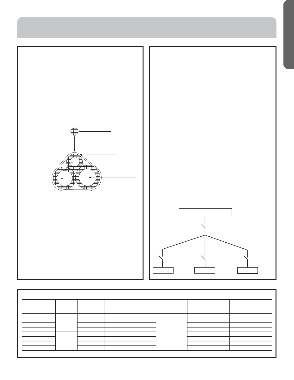
Insulation
• HP gas pipe, suction gas pipe, and liquid pipe should be heat
insulated separately.
• The insulation material for the hot gas and suction lines
should withstand a temperature of 248°F (120°C). The liquid
line insulation should be able to withstand temperatures over
158°F (70°C).
• The material thickness should be over 1/2in.(10mm), when
ambient temp. is 86°F (30°C), and the relative humidity is over
80%, the material thickness should be over 3/4in.(20mm).
• The material should fit over the pipe closely without gap, then
be wrapped with adhesive tape. The communication wire
should not run together with the insulation material and should
be spaced at least 8 inches.
Secure the refrigerant pipe.
• The refrigerant lines will expand and contract during operation
so it is important that they be supported properly.
• Support lines every 7 to 10 ft.
• Check leakage on the pipe connections when installation is
finished.
• When checking leakage of refrigerant or reinstalling the
system, make sure to turn the compressor off and then
disconnect the pipe.
• Do not operate the compressor in condition of unconnected
pipe, refrigerant leakage and incorrectly connected pipe. If not
it may cause air to flow into compressor and lead an explosion
or malfunction.
• If there's any possibility of small animals entering the pipe
from outlet, then block it.
Electric Wiring and Applications (Cont.)
Electric Wiring and Applications
1. Please follow all national and local electric codes. All
wiing materials should comply with local and national
codes. All work should be done by professional
electricians.
2. Power supply must be provided at the rating plate level.
Fluctuations in the power supply must be less than 2%
phase to phase. Outdoor and indoor units must have
their own dedicated power supply.
3. Electrical connections from disconnects to equipment
should be properly secured.
4. Power conductors should be sized in accordance with
national and local codes. Equipment must be properly
grounded to earth through the circuit breaker panel.
5. Equipment electrical circuits must be protected by the
properly sized breaker per codes.
6. Do not add filter capacitors to the power supply
servicing this equipment.
7. Follow these installation instructions when wiring the
equipment to avoid injury or accidents.
8. The unit must be reliably grounded to meet the national
requirements.
9. All electrical installations must be carried out by
professionals in accordanve with local laws, regulations,
and corresponding instructions.
Power Control Cabinet
Outdoor 1 Outdoor 2
Circuit breaker
Circuit breaker
Circuit breaker
Circuit breaker
Outdoor 3
Suction Gas Pipe
Heat Insulator
Adhesive Tape
Over 8in. (200mm)
Liquid Pipe
HP Gas Pipe
Connection Wire
Model
Power
Source
Maximum load
current (A)
Circuit
breaker (A)
Each model
circuit breaker
(A)
Leakage current
(mA) response
time (S)
Minimum sectional
area of power line AWG
(mm
2
)
Minimum sectional
area of earthing line
AWG (mm
2
)
MVHR072ME2CA
208/230V~
60Hz 3PH
30 40 40
30mA, below
0.1s
7(10) 7(10)
MVHR096ME2CA 38 50 50 7(10) 7(10)
MVHR120ME2CA 41 60 60 7(10) 7(10)
MVHR144ME2CA 56 80 80 3(25) 5(16)
MVHR072ME4CA
460V~
60Hz 3PH
16 20 20 9(6) 9(6)
MVHR096ME4CA 20 25 25 9(6) 9(6)
MVHR120ME4CA 22 30 30 9(6) 9(6)
MVHR144ME4CA 30 40 40 7(10) 7(10)
Loading ...
Loading ...
Loading ...