Loading ...
Loading ...
Loading ...
31-5000573 Rev. 2 25
ENGLISH
INSTALLATION INSTRUCTIONS
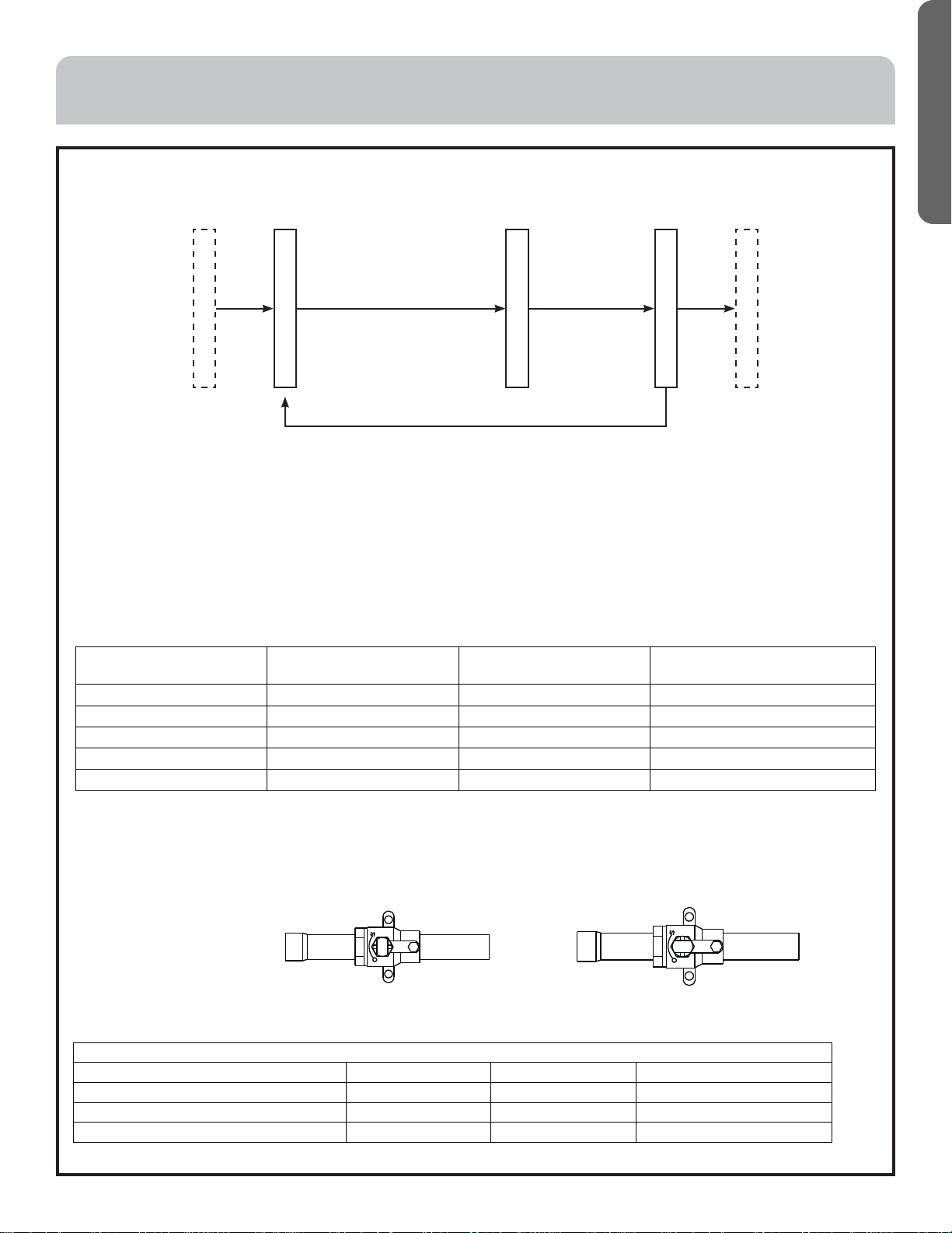
Evacuation
Connect the vacuum pump at both liquid and suctions valves
Operation Procedure:
Leakage Test passed
Evacuation Begins
Evacuation Ends
Check Vacuum
Change Refrigerant
After reaching 0.007psi or
less than 350 microns, let the
vacuum run continuously
Vacuum should
not rise above 500
microns
If the vacuum pointer rises, it shows there is water or leakage in the
system. Please check and modify it, then evacuate again.
IMPORTANT:
• To prevent the oil going into the pipe, please use the special tool for R410A, especially for gauge manifold and charging
hose.
• To prevent the oil from going into the refrigerant cycle, please use the anti-counter flow adapter.
• Release the refrigerant check valve during outdoor unit maintenance. Set the relative dip switch when evacuating
system.
Tighten torque as the table below shows:
Stop valve diameter
(in.)
Fastening torque
(ft.lb)
Fastening angle
(°)
Recommended tool length
in(mm)
1/4 10.33 to 13.28 45~60 5-29/32(150)
3/8 25.08 to 30.98 30~45 7-7/8 (200)
1/2 36.14 to 44.99 30~45 9-13/16 (250)
5/8 50.15 to 60.48 15~20 11-13/16(300)
3/4 61.96 to 72.28 15~20 11-13/16(300)
• Take down the valve cap, suction gas pipe, HP gas pipe turns to "open"
• Turn the liquid pipe and the oil equalization pipe with hexangular spanner until it stops. If opening the valve strongly, the
valve will be damaged.
• Tighten the valve cap.
Check valve operation
Open/ close method:
"open"state "close"state
Tighten torque as the table below:
Tighten torque N·m
Shaft (valve body) Cap (cover) T-shape nut (check joint)
For suction gas pipe and HP gas pipe Less than 7 Less than 30 13
For liquid pipe 7.85 (MAX15.7) 29.4 (MAX39.2) 8.8 (MAX14.7)
For oil equalization pipe 4.9 (MAX11.8) 16.2 (MAX24.5) 8.8 (MAX14.7)
Loading ...
Loading ...
Loading ...