Model 201 Media Installation Page 1
MEDIA REPLACEMENT
INSTRUCTIONS FOR AIR CLEANER
MODELS 2200 & 2250
Identify your model, read instructions and review illustrations carefully prior to maintenance.
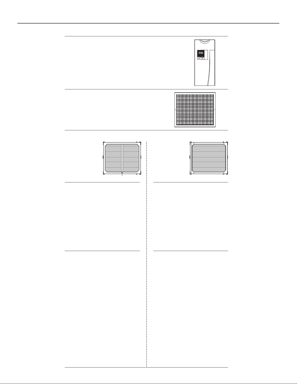
STEP 1: MODEL 2200 – TO REMOVE INNER ASSEMBLY.
A. Turn off furnace blower.
B. Remove access door.
C. Slide out inner assembly.
STEP 5: MODEL 2200 – TO RE-INSTALL INNER ASSEMBLY.
A. Slide inner assembly into outer housing.
B. Replace access door.
C. Turn on furnace blower.
MODEL 2250 – TO RE-INSTALL GRILLE ASSEMBLY.
A. Slightly compress spring clips and slide grille assembly into opening.
B. Release pressure on spring clips and allow clips to catch.
C. Hold unit firm to wall or ceiling and tighten two knobs.
D. Turn on blower.
MODEL 2250 – TO REMOVE GRILLE ASSEMBLY.
A. Turn off blower.
B. Loosen two knobs on grille (they remain attached).
C. Pull out grille assembly until spring clips engage.
D. Compress spring clips and remove grille assembly.
STEP 2: Before proceeding, determine which style Aprilaire
®
inner housing you have.
If your inner housing
has a center aluminum
brace as shown here
and black holding
brackets, then follow
the instructions below
and Figures 1-3.
If your inner housing
does not have a center
aluminum brace as
shown here and is
equipped with hinged
brackets, then follow
the instructions below
and Figures 4-6.
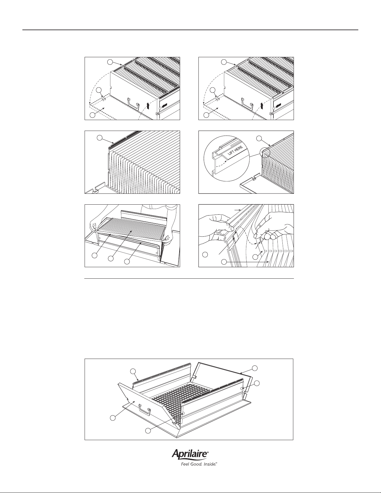
STEP 3: To remove media, see Figures 1-3.
A. Place inner assembly so that all pleat spacers
(Figure 1F) are up. Open both end panels (Figure
1A), by unsnapping side latches (Figure 1B).
B. Remove pleat spacers from black holding
brackets (Figure 1F) by lifting and tilting both
ends at the same time.
C. Remove black holding brackets (Figure 2E).
D. On side farthest away, lift cardboard flap clear
(Figure 3C). Compress media, lift to remove from
near side and discard properly.
STEP 3: To remove media, see Figures 4-6.
A. Place inner assembly so that all pleat spacers
(Figure 4F) are up. Open both end panels (Figure
4A), by unsnapping side latches (Figure 4B).
B. Remove all pleat spacers from hinged brackets
(Figure 4F) by lifting and tilting both ends at the
same time.
C. Open hinged brackets (Figure 5E) by lifting along
entire inner edge.
D. On side farthest away, lift cardboard flap clear
(Figure 6C). Compress media, lift to remove from
near side and discard properly.
STEP 4: To install media, see Figures 1-3. This
media is special material and should be handled
very carefully to avoid any damage that would
affect its performance.
A. Place one cardboard flap (Figure 3C) over the
flange (Figure 3G) on the side farthest away.
Expand media (Figure 3D) towards you and
place other cardboard flap over the flange on
the near side. Be sure media is centered over
the opening in the inner assembly.
B. Place black holding brackets (Figure 2E)
over cardboard flaps (Figure 3C) as shown in
Figure 2.
C. Carefully place one pleat spacer finger into
each pleat starting at either end next to the
alignment yarn. The ends of the pleat spacers
align with notches in the black holding
brackets and snap into place.
D. Close end panels (Figure 1A) and snap side
latches closed (Figure 1B).
STEP 4: To install media, see Figures 4-6. This
media is special material and should be handled
very carefully to avoid any damage that would
affect its performance.
A. Place one cardboard flap (Figure 6C) over the
hooks and through the slots of the flap (Figure
6G) on the side farthest away. Expand media
(Figure 6D) towards you and place other
cardboard flap over the hooks and through the
slots on the near side. Be sure media is centered
over the opening in the inner assembly.
B. Close hinged brackets (Figure 5E) over
cardboard flaps (Figure 6C) centered on sides as
shown in Figure 5. Press firmly along entire edge
of both brackets so brackets snap into place.
C. Carefully place one pleat spacer finger into
each pleat starting at either end next to the
alignment yarn. The ends of the pleat spacers
align with notches in the hinged brackets and
snap into place.
D. Close end panels (Figure 4A) and snap side
latches closed (Figure 4B).
Instructions for units with black holding
brackets and center aluminum brace on intake
side, see Figures 1-3.
Instructions for units with hinged brackets
without center aluminum brace on intake side,
see Figures 4-6.
Figure 1
Figure 2
Figure 3
Figure 4
Figure 5
Figure 6
Model 2250
Grille
Assembly
Housing
CENTER BRACE
A
B
F
E
Hinged Flap Open
Hook
Slot
G
D
C
A
B
F
E
E
A
A
B
B
C
D
G
Model 201 Media Installation Page 2
P.O. Box 1467 • Madison, WI 53701-1467 • Phone: 800/334-6011 • Fax: 608/257-4357 • www.aprilaire.com
10010438 6.13
B2701309A
© 2013 Aprilaire – A division of
Research Products Corporation
MEDIA REPLACEMENT
INSTRUCTIONS FOR AIR CLEANER
MODELS 2200 & 2250
Identify your model, read instructions and review illustrations carefully prior to maintenance.
STEP 1: MODEL 2200 – TO REMOVE INNER ASSEMBLY.
A. Turn off furnace blower.
B. Remove access door.
C. Slide out inner assembly.
STEP 5: MODEL 2200 – TO RE-INSTALL INNER ASSEMBLY.
A. Slide inner assembly into outer housing.
B. Replace access door.
C. Turn on furnace blower.
MODEL 2250 – TO RE-INSTALL GRILLE ASSEMBLY.
A. Slightly compress spring clips and slide grille assembly into opening.
B. Release pressure on spring clips and allow clips to catch.
C. Hold unit firm to wall or ceiling and tighten two knobs.
D. Turn on blower.
MODEL 2250 – TO REMOVE GRILLE ASSEMBLY.
A. Turn off blower.
B. Loosen two knobs on grille (they remain attached).
C. Pull out grille assembly until spring clips engage.
D. Compress spring clips and remove grille assembly.
STEP 2: Before proceeding, determine which style Aprilaire
®
inner housing you have.
If your inner housing
has a center aluminum
brace as shown here
and black holding
brackets, then follow
the instructions below
and Figures 1-3.
If your inner housing
does not have a center
aluminum brace as
shown here and is
equipped with hinged
brackets, then follow
the instructions below
and Figures 4-6.
STEP 3: To remove media, see Figures 1-3.
A. Place inner assembly so that all pleat spacers
(Figure 1F) are up. Open both end panels (Figure
1A), by unsnapping side latches (Figure 1B).
B. Remove pleat spacers from black holding
brackets (Figure 1F) by lifting and tilting both
ends at the same time.
C. Remove black holding brackets (Figure 2E).
D. On side farthest away, lift cardboard flap clear
(Figure 3C). Compress media, lift to remove from
near side and discard properly.
STEP 3: To remove media, see Figures 4-6.
A. Place inner assembly so that all pleat spacers
(Figure 4F) are up. Open both end panels (Figure
4A), by unsnapping side latches (Figure 4B).
B. Remove all pleat spacers from hinged brackets
(Figure 4F) by lifting and tilting both ends at the
same time.
C. Open hinged brackets (Figure 5E) by lifting along
entire inner edge.
D. On side farthest away, lift cardboard flap clear
(Figure 6C). Compress media, lift to remove from
near side and discard properly.
STEP 4: To install media, see Figures 1-3. This
media is special material and should be handled
very carefully to avoid any damage that would
affect its performance.
A. Place one cardboard flap (Figure 3C) over the
flange (Figure 3G) on the side farthest away.
Expand media (Figure 3D) towards you and
place other cardboard flap over the flange on
the near side. Be sure media is centered over
the opening in the inner assembly.
B. Place black holding brackets (Figure 2E)
over cardboard flaps (Figure 3C) as shown in
Figure 2.
C. Carefully place one pleat spacer finger into
each pleat starting at either end next to the
alignment yarn. The ends of the pleat spacers
align with notches in the black holding
brackets and snap into place.
D. Close end panels (Figure 1A) and snap side
latches closed (Figure 1B).
STEP 4: To install media, see Figures 4-6. This
media is special material and should be handled
very carefully to avoid any damage that would
affect its performance.
A. Place one cardboard flap (Figure 6C) over the
hooks and through the slots of the flap (Figure
6G) on the side farthest away. Expand media
(Figure 6D) towards you and place other
cardboard flap over the hooks and through the
slots on the near side. Be sure media is centered
over the opening in the inner assembly.
B. Close hinged brackets (Figure 5E) over
cardboard flaps (Figure 6C) centered on sides as
shown in Figure 5. Press firmly along entire edge
of both brackets so brackets snap into place.
C. Carefully place one pleat spacer finger into
each pleat starting at either end next to the
alignment yarn. The ends of the pleat spacers
align with notches in the hinged brackets and
snap into place.
D. Close end panels (Figure 4A) and snap side
latches closed (Figure 4B).
Instructions for units with black holding
brackets and center aluminum brace on intake
side, see Figures 1-3.
Instructions for units with hinged brackets
without center aluminum brace on intake side,
see Figures 4-6.
Figure 1
Figure 2
Figure 3
Figure 4
Figure 5
Figure 6
Model 2250
Grille
Assembly
Housing
CENTER BRACE
A
B
F
E
Hinged Flap Open
Hook
Slot
G
D
C
A
B
F
E
E
A
A
B
B
C
D
G