
Model AIF10
Automatic Iron and
Hydrogen Sulfide Filter
AUTOMATIC WATER FILTRATION
with High-Flow 1” Valve
Installation
Operation
Maintenance
Repair Parts
Manufactured and warranted by
Water Channel Partners
1890 Woodlane Drive
Woodbury, MN 55125
7320079 (Rev. S 3/26/20)

2
TABLE OF CONTENTS
Page
I
nspect Shipment / Safety Guides . . . . . . . . . . . . . . . . . . . . . . . . . . . . . . . . . . . . . . . . . . . . . . . . . . . . . . . . . . . . . . . 3
Specifications & Dimensions . . . . . . . . . . . . . . . . . . . . . . . . . . . . . . . . . . . . . . . . . . . . . . . . . . . . . . . . . . . . . . . . . . . 4
Before Starting Installation . . . . . . . . . . . . . . . . . . . . . . . . . . . . . . . . . . . . . . . . . . . . . . . . . . . . . . . . . . . . . . . . . . . . 5
Typical Installation Illustrations . . . . . . . . . . . . . . . . . . . . . . . . . . . . . . . . . . . . . . . . . . . . . . . . . . . . . . . . . . . . . . . . . 6
I
nstallation Instructions . . . . . . . . . . . . . . . . . . . . . . . . . . . . . . . . . . . . . . . . . . . . . . . . . . . . . . . . . . . . . . . . . . . . . . 7-9
Programming the Electronic Controller . . . . . . . . . . . . . . . . . . . . . . . . . . . . . . . . . . . . . . . . . . . . . . . . . . . . . . . 10-11
C
ustomizing Features / Options . . . . . . . . . . . . . . . . . . . . . . . . . . . . . . . . . . . . . . . . . . . . . . . . . . . . . . . . . . . . . 12-14
Adding Potassium Permanganate Powder to Feeder Tank . . . . . . . . . . . . . . . . . . . . . . . . . . . . . . . . . . . . . . . . . . 15
Cleaning the Nozzle & Venturi . . . . . . . . . . . . . . . . . . . . . . . . . . . . . . . . . . . . . . . . . . . . . . . . . . . . . . . . . . . . . . . . 15
Troubleshooting . . . . . . . . . . . . . . . . . . . . . . . . . . . . . . . . . . . . . . . . . . . . . . . . . . . . . . . . . . . . . . . . . . . . . . . . . 16-19
Troubleshooting Guide . . . . . . . . . . . . . . . . . . . . . . . . . . . . . . . . . . . . . . . . . . . . . . . . . . . . . . . . . . . . . . . . . . . . . . 16
Schematic . . . . . . . . . . . . . . . . . . . . . . . . . . . . . . . . . . . . . . . . . . . . . . . . . . . . . . . . . . . . . . . . . . . . . . . . . . . . . . . . 17
Exploded View & Parts List . . . . . . . . . . . . . . . . . . . . . . . . . . . . . . . . . . . . . . . . . . . . . . . . . . . . . . . . . . . . . . . . 20-23
WATER FILTER WARRANTY
Warrantor: Water Channel Partners, 1890 Woodlane Drive, Woodbury, MN 55125
Warrantor guarantees, to the original owner, that:
One Year Full Warranty:
● For a period of one (1) year from the date of purchase, all parts will be free from defects in materials and workman-
ship and will perform their normal functions.
Limited Warranties:
● For a period of ten (10) years from the date of purchase, the fiberglass mineral tank, excluding mineral, will not rust,
corrode, leak, burst, or in any other manner, fail to perform their proper functions.
● For a period of three (3) years from the date of purchase, the electronic control board and valve body will be free of
defects in materials and workmanship and will perform their normal functions.
If, during such respective period, a part proves to be defective, Warrantor will ship a replacement part directly to your
home, without charge.
General Provisions
Damage to any part of this water filter because of misuse, misapplication, neglect, alteration, accident, installation or oper-
ation contrary to our printed instructions, or damage caused by any unusual force of nature such as, but not limited to,
freezing, flood, hurricane, tornado, or earthquake is not covered by this warranty. In all such cases, regular parts and serv-
ice charges will apply.
We assume no warranty liability in connection with this water filter other than specified herein. This warranty is in lieu of all
other warranties, expressed or implied, including warranties of fitness for a particular purpose. We do not authorize any
person or representative to assume for us any other obligations on the sale of this water filter.
Should a defect or malfunction occur, contact your contractor. If you are unable to contact your contractor, return the part,
freight prepaid, directly to the factory at the address below. Enclose with the part a full description of the problem, with
your name, full address, date purchased, model and serial numbers, and selling contractor's name and address. We will
repair or replace the part and return it to you at no cost if our repair department determines it to be defective under the
terms of the warranty.
This warranty gives you specific legal rights and you may have other rights which vary from state to state.
This water filter is manufactured by
Water Channel Partners, 1890 Woodlane Drive, Woodbury, MN 55125
Customer Information Telephone No. 1-800-972-0136

Inspect Shipment
The filter is shipped in one carton, including the
potassium permanganate feeder assembly. The filter
i
s completely assembled at the factory, except as
required at installation. The filter’s mineral tank is
loaded with the proper quantity of manganese green-
sand, gravel and sand.
Thoroughly check the filter system for possible ship-
ping damage and parts loss. Also inspect and note
a
ny damage to the shipping carton.
R
emove and discard (or recycle) all packing materials.
To avoid loss of small parts, we suggest you keep the
s
mall parts in the parts bag until you are ready to use
them.
Recommended maximum allowable inlet water
pressure is 80 psi. Use a pressure reducing valve if
necessary. Be sure the addition of a pressure reduc-
ing valve will not reduce the flow to less than the 5
gallons per minute needed for backwash.
The filter works on 24V DC electrical power, supplied
by a direct plug-in power supply (included). Be sure
to use the included power supply, and plug it into a
nominal 120V, 60 Hz household outlet that is in a dry
location only, grounded and properly protected by
an overcurrent device such as circuit breaker or fuse.
This system is not intended to be used for treating
water that is microbiologically unsafe or of unknown
quality without adequate disinfection before or after
the system.
European Directive 2002/96/EC requires all
electrical and electronic equipment to be
disposed of according to Waste Electrical
and Electronic Equipment (WEEE) require-
ments. This directive or similar laws are in
place nationally and can vary from region to
region. Please refer to your state and local
laws for proper disposal of this equipment.
Safety Guides
Follow the installation instructions carefully. Failure to
install the filter properly voids the warranty.
Before you begin installation, read this entire manual.
Then obtain all the materials and tools you will need
to make the installation.
Check local plumbing and electrical codes. The
installation must conform to them.
Use only lead-free solder and flux for all sweat-sol-
der connections as required by state and federal
codes.
Use care when handling the filter. Do not turn upside
down, drop, or set on sharp protrusions.
Do not locate the filter where freezing temperatures
occur. Do not attempt to filter water over 120°F.
Freezing, or hot water damage voids the warranty.
Avoid installing in direct sunlight. Excessive sun heat
may cause distortion or other damage to non-metallic
parts.
The filter requires a minimum water flow of 5 gallons
per minute at the inlet for backwash.
3
4
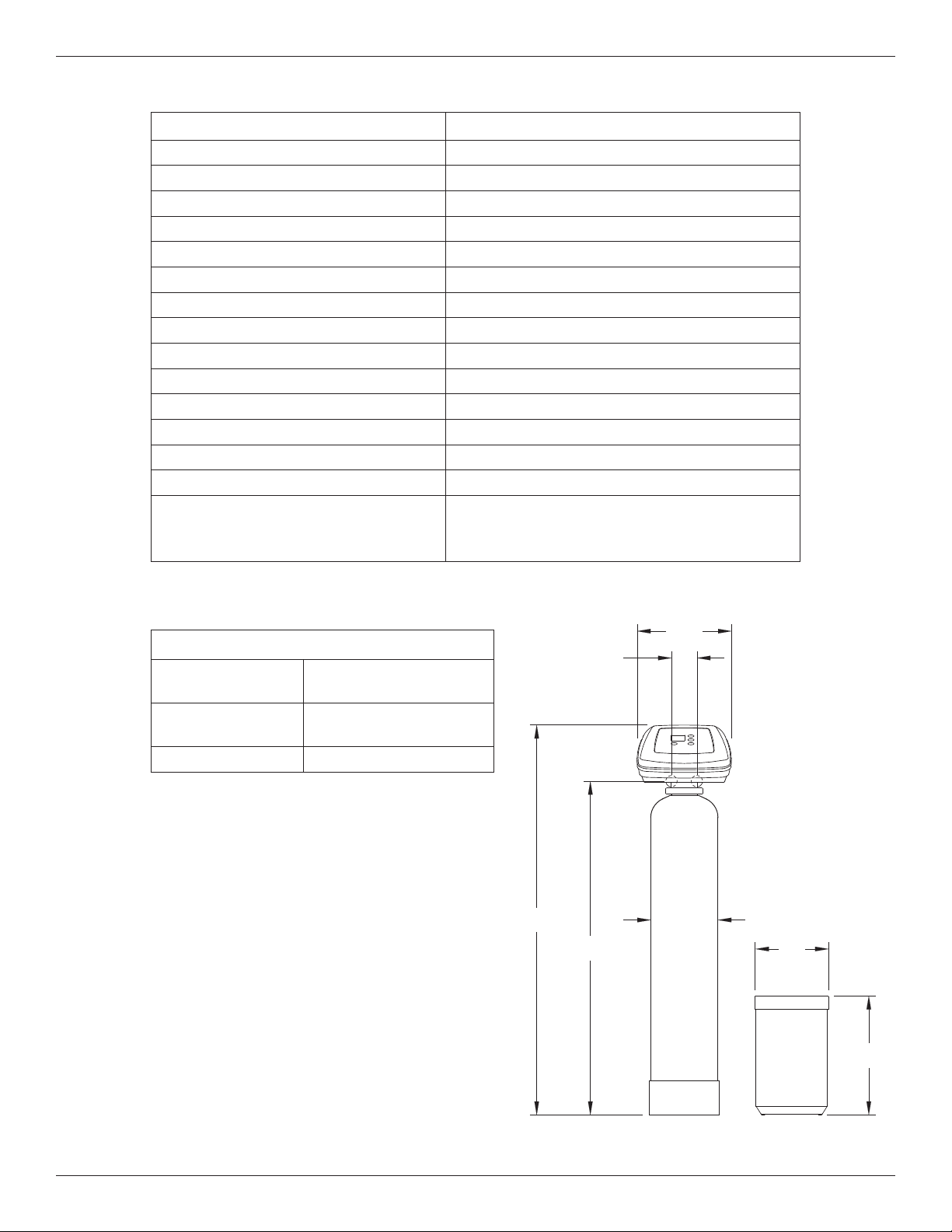
Specifications & Dimensions
Automatic Iron Filter AIF10
Model Code HIF10
Type of Mineral Greensand Plus
Amount of Mineral 1.0 cu. ft.
Amount of Gravel Base 17 lbs.
Amount of Filter Sand 10 lbs.
Inlet Water Pressure Limits (min./max.) 40 - 125 psi
Nominal Mineral Tank Size 10” dia. x 47” tall
Water Temperature Limits (min./max.) 40 - 100 °F
Minimum Inlet Water Flow 7 gal./min.
Service Flow Rate* 2 - 5 gal./min.
Backwash Flow Rate 5 gal./min.
Inlet/Outlet Pipe Size 1”
Maximum Iron Removal 20 ppm
Supply Water Minimum pH 7
Capacity Rating
270 gal. with 10.6 ppm Hydrogen Sulfide (H
2
S)
620 gal. with 10.4 ppm Ferrous Iron (FeSO
4
)
1900 gal. with 2.01 ppm Manganese (MnSO
4
)
* Well pump must be able to provide the minimum flow for 30+ minutes.
14"
OUTLET
INLET
INLET -
OUTLET
3-3/4"
58-1/8" 10-1/2"
49-3/4"
18"
11"
DIA.
FIG. 1
3-3/4”
INLET
OUTLET
INLET -
OUTLET
14”
58-1/8”
49-3/4”
10-1/2”
18”
11”
DIA.
Contaminant Removal
Clear and/or
Red Water Iron
Removes up to 15 ppm
Hydrogen Sulfide
(rotten egg smell)
Removes up to 2 ppm
Manganese Removes up to 5 ppm

5
Before Starting Installation
WHERE TO INSTALL THE FILTER
= Place the filter as close as possible to the pressure
tank (well system) or water meter (city water).
= Place the filter as close as possible to a floor drain,
or other acceptable drain point (laundry tub, sump,
standpipe, etc.). The drain point must be able to
discharge the backwash flow rates shown on page
3.
= Connect the filter to the main water supply pipe
UPSTREAM OF the water heater. DO NOT RUN
HOT WATER THROUGH THE FILTER. The tem-
perature of water passing through the filter must be
less than 120°F.
= Keep outside faucets on unfiltered water to con-
serve filtering capacity.
= Do not install the filter in a place where it could
freeze. Damage caused by freezing is not covered
by the warranty.
= Put the filter in a place water damage is least likely
to occur if a leak develops. The manufacturer will
not repair or pay for water damage.
= A 120V, 60 Hz electrical outlet, to plug the included
power supply into, is needed near the filter. Be
sure the electrical outlet and power supply are in an
inside location, to protect from wet weather.
= If installing in an outside location, you must take the
steps necessary to assure the filter, installation
plumbing, wiring, etc., are as well protected from
the elements, contamination, vandalism, etc., as
when installed indoors.
= Keep the filter out of direct sunlight. The sun's heat
may soften and distort plastic parts.
TOOLS, PIPE & FITTINGS,
OTHER MATERIALS YOU WILL NEED
= Plastic inlet and outlet fittings included with the filter
allow water flow equivalent to 1 inch nominal pipe.
To maintain full valve flow, 1” pipes to and from the
filter fittings are recommended. Do not reduce the
pipes to less than 3/4” size. Follow local codes.
= Use copper, brass, or galvanized pipe and fittings.
Some codes may also allow CPVC plastic pipe.
= ALWAYS install the included bypass valve, or 3
shut-off valves. Bypass valves let you turn off
water to the filter for repairs if needed, but still have
water available to the house pipes.
= Drain hose, 5/8” inside diameter minimum, with a
garden hose connection on one end, is needed for
the valve drain. See step 5 on page 8.
= If a rigid valve drain is needed, to comply with
plumbing codes, you can buy the parts needed (see
page 6) to connect a 1/2” minimum copper tubing
drain.
= Potassium permanganate is needed for regenera-
tion of the filter mineral. It is available from most
dealers of water conditioning equipment. This filter
uses from 2 to 5 ounces of potassium perman-
ganate each regeneration.
PLAN HOW YOU WILL INSTALL THE FILTER
You must first decide how to run in and out pipes to
the filter. Look at the house main water pipe at the
point where you will connect the filter. Is the pipe sol-
dered copper, glued plastic, or threaded brass/galva-
nized? What is the pipe size?
Now look at the typical installation illustration on page
6. Use it as a guide when planning your particular
installation. Be sure to direct incoming, unfiltered
water to the filter valve inlet fitting. The valve ports are
marked IN and OUT.
6
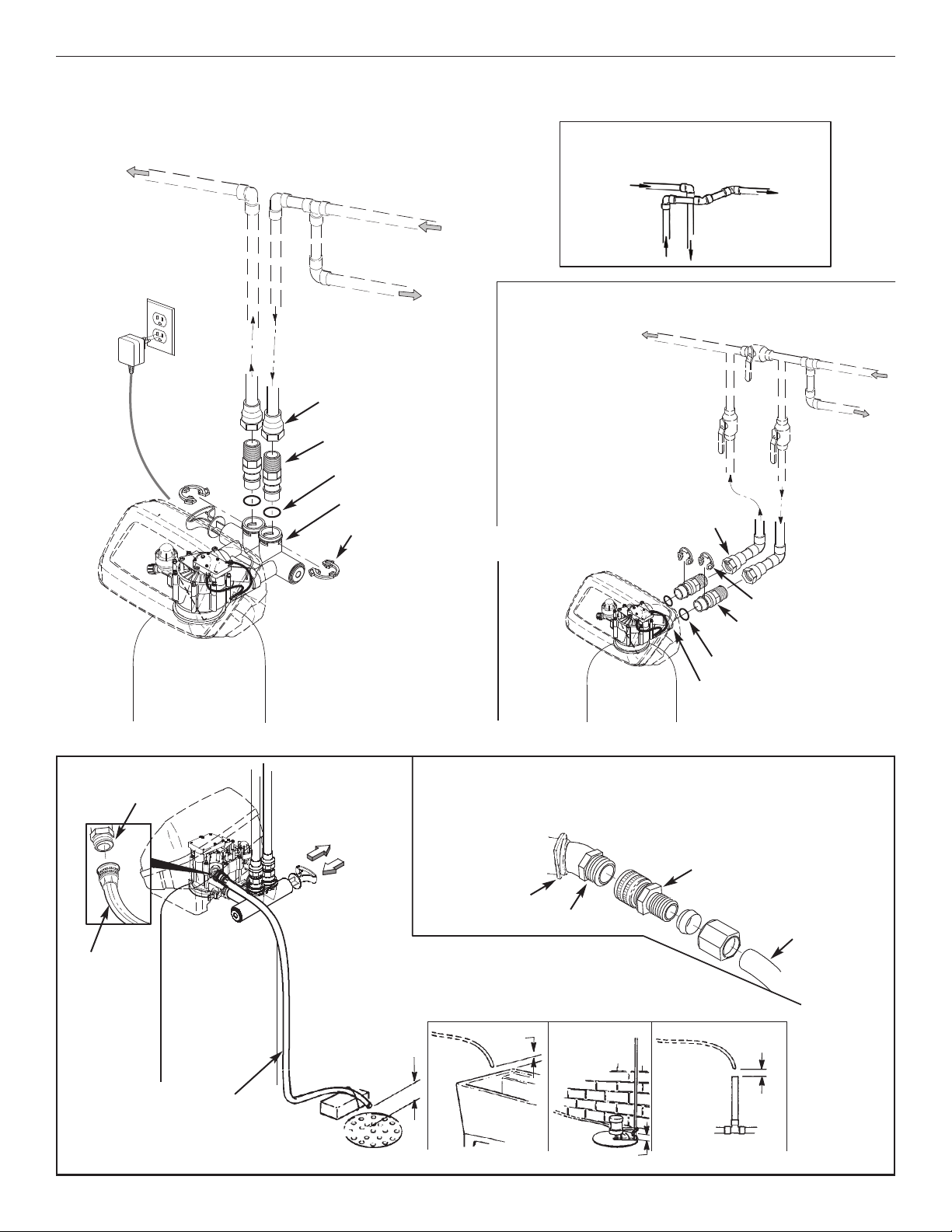
Typical Installation Illustrations
FIG. 4
Drain
Fitting
Valve
Drain
Hose
Valve
Drain
Hose
1-1/2”
Air Gap
1-1/2”
Air Gap
1-1/2”
Air Gap
1-1/2” Air Gap
LAUNDRY
TUB
SUMP
STAND
PIPE
FLOOR
DRAIN
To standpipe, sump, laundry
tub or other suitable drain.
1/2” I.D.
(minimum)
copper tube
Push in for
Bypass
Clip
Drain Fitting
CONNECTING A RIGID VALVE DRAIN TUBE
To adapt a copper tube to the filter, buy a compression fitting (garden hose thread to
1/2” I.D. minimum tube and necessary tubing from your local hardware store.
Adaptor, garden hose
thread to compression
Pull out for
filtered water
“Service”
FIG. 3FIG. 2
INSTALLATION USING 3-VALVE BYPASS
M
A
IN
WAT
E
R
PIPE
M
A
IN
WAT
E
R
P
IP
E
INSTALLATION USING INCLUDED BYPASS VALVE
CROSS-OVER
Use if water supply flows from the left.
Include single or 3-valve bypass.
Filtered
W
ater OUT
Unfiltered
Water IN
Unfiltered Water
to Outside Faucets
120V,
60 Hz
Outlet
FILTERED
W
ATER
TO FILTER
INLET
U
NFILTERED
W
ATER
FROM FILTER
OUTLET
B
YPASS
Valve
OUTLET
Valve
I
NLET
Valve
1” NPT
Adaptor (2)
not included
Clip (2)*
O-Ring Seal (2)*
1” NPT Installation
Adaptor (2)*
Valve
INLET
For filtered water SERVICE:
-Open the inlet and outlet
valves
For unfiltered BYPASS:
-Close the inlet and outlet
valves
-Open the bypass valve
* Included with filter - Pipe and
fittings supplied by installer.
1” NPT
Adaptor (2)
not included
1” NPT Installation
Adaptor (2)*
Bypass Valve*
Clip (4)*
O-Ring Seal (2)*
Power
Supply
7
Installation Instructions
1. TURN OFF WATER SUPPLY
a. Close the main water supply valve near the well
pump or water meter.
b. Shut off the electric or fuel supply to the water
heater.
c. Open high and low faucets to drain all water from
the house pipes.
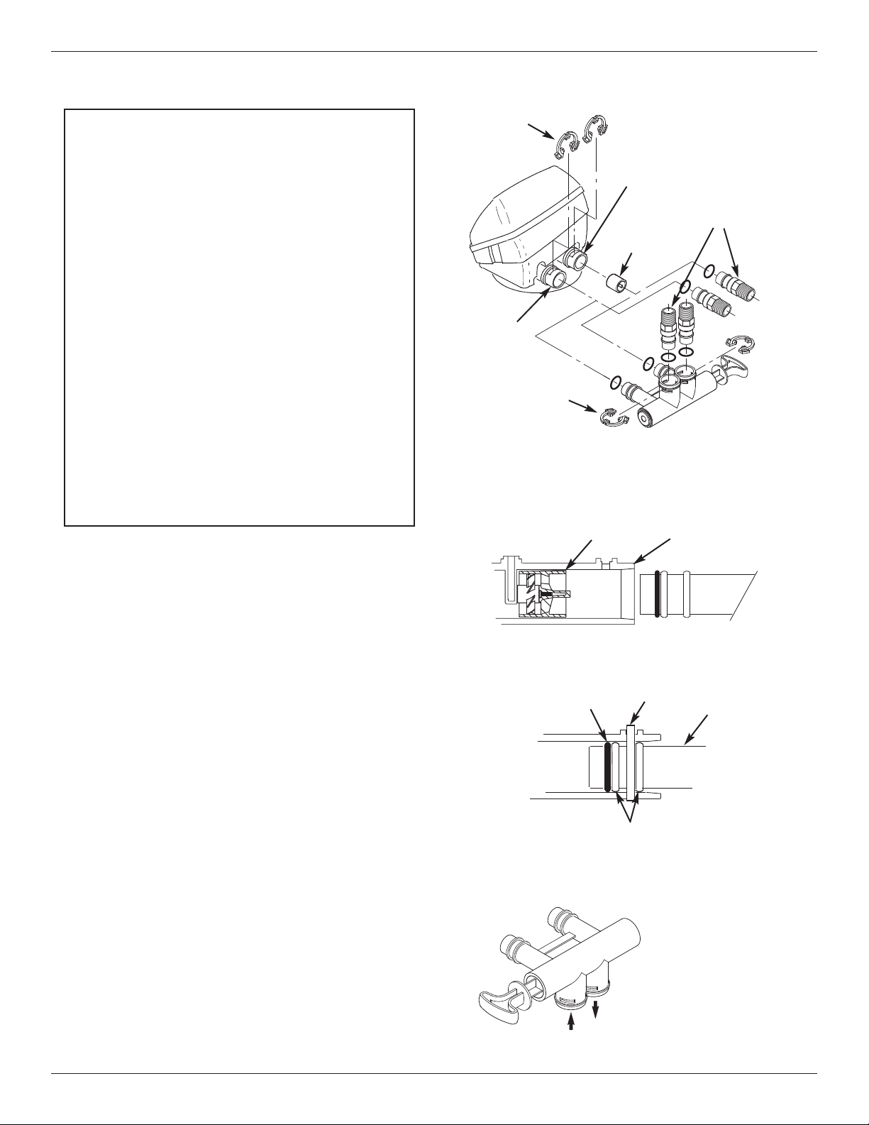
2. INSTALL BYPASS VALVE AND/OR
PLASTIC INSTALLATION ADAPTORS
a. If installing a single bypass valve, push the bypass
valve, with lubricated o-ring seals in place, into the
valve inlet and outlet ports (See Figures 2 & 5).
- OR -
b. If installing a 3-valve bypass system, slide plastic
installation adaptors, with lubricated o-ring seals in
place, into the valve inlet and outlet ports (See
Figures 3 & 5).
c. Make sure the turbine support is in place in the
valve outlet, as shown in Figure 6.
d. Snap the two large plastic clips in place on the inlet
and outlet ports, from the top, down (See Figure 7).
Be sure they snap into place. Pull on the bypass
valve, or installation adaptors, to make sure they
are held securely in place.
Turbine
Support
Valve
Outlet
FIG. 6
FIG. 7
O-ring
Clip
Cross section of
valve inlet or outlet
Bypass valve or
plastic adaptor
Snap clips into place between
larger diameter rings
FIG. 8
Turn the bypass
valve downward if
connecting to floor
level plumbing
INLET
OUTLET
FIG. 5
INLET
OUTLET
Clip (2)
Bypass
Valve
Clip (2)
Turbine
Support
P
lastic installation
adaptors (install in
filter valve or
bypass valve)
IMPORTANT SANITIZING PROCEDURES
C
are is taken at the factory to keep your water filter
clean and sanitary. Materials used to make the fil-
ter will not infect or contaminate your water sup-
ply, and will not cause bacteria to form or grow.
However, during shipping, storage, installing and
operating, bacteria could get into the filter or
media. For this reason, sanitizing as follows is
suggested* when installing.
a. Pour about 1 ounce of the following disinfectant
into the valve inlet fitting:
= Calcium hypochlorite, available in granular
or tablet form, under trade names such as
Perchloron or HTH - OR -
= Common 5.25% household bleach (Clorox
or other brands).
b. Complete the sanitizing procedures in steps 7
and 10, below.
*NOTE: Sanitizing is recommended by the Water Quality
Association for disinfecting. On some water
supplies, they suggest periodic sanitizing.

8
Installation Instructions
4. COLD WATER PIPE GROUNDING
CAUTION: The house cold water pipe (metal only) is
often used as a ground for the house elec-
trical system, The 3-valve bypass type of
installation, shown in Figure 3, will maintain
ground continuity. If you use a plastic
bypass valve at the unit, continuity is bro-
ken. To restore the ground, do the follow-
ing:
a. Install a #4 copper wire across the removed section
of main water pipe, securely clamping it at both
ends (See Figure 9) - parts not included.
NOTE: Check local plumbing and electrical codes for
proper installation of grounding. The installa-
tion must conform to them. In Massachusetts,
plumbing codes of Massachusetts shall be
conformed to. Consult with your licensed
plumber.
5. INSTALL VALVE DRAIN HOSE
a. Take a length of 5/8” inside diameter garden hose
and attach to the valve drain fitting (See Figure 4 on
page 6).
b. Locate the other end of the hose at a suitable drain
point (floor drain, sump, laundry tub, etc.). Check
and comply with local codes. Refer to Figure 4 on
page 6 if codes require a rigid pipe drain run.
IMPORTANT: Use high quality, thick wall hose that will
not easily kink or collapse. The filter will
not backwash properly if water cannot
exit this hose during recharges.
c. Tie or wire the hose in place at the drain point.
Water pressure will cause it to whip during the back-
wash and fast rinse cycles of recharge. Also pro-
vide an air gap of at least 1-1/2” between the end of
the hose and the drain point. An air gap prevents
possible siphoning of sewer water, into the filter, if
the sewer should back up.
d. If raising the drain hose overhead is required to get
to the drain point, do not raise higher than 8 feet
above the floor. Elevating the hose may cause a
back pressure that could reduce backwash flow and
proper mineral bed cleaning.
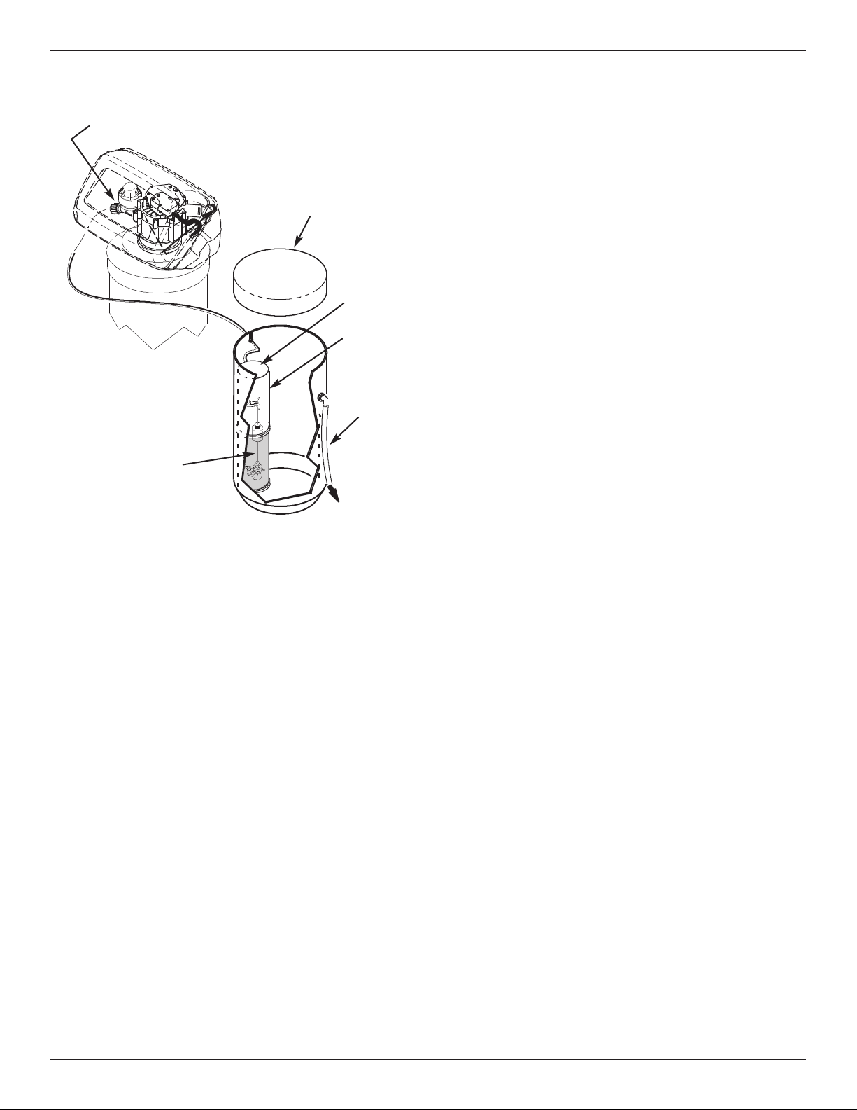
6. CONNECT THE POTASSIUM
PERMANGANATE FEEDER
a. Run the 5/16” tubing from the brine valve to the noz-
zle assembly on the filter (See Figure 10). Use
slots in the tank and both brinewells to hold tubing
in place.
b. Attach a length of 3/8” or 7/16” I.D. drain hose (7
feet included) to the hose fitting on the tank side-
wall. Place the outlet of the hose over the floor
drain. This is a gravity drain, and must flow down-
ward. Provide an air gap as you did with the valve
drain hose.
CAUTION: Do not omit this hose. If the feeder tank
should overfill, the drain hose carries
excess potassium permanganate solution
to the drain. This solution will deeply stain
anything it contacts.
c. With brinewell covers in place, pour the included 2
lbs. of potassium permanganate powder into the
feeder tank, then about 1/2 gallon of water. Install
the tank cover.
3. COMPLETE PLUMBING TO AND FROM
THE FILTER
Using the “Typical Installation Illustrations” on page 6
as a guide, observe all of the following cautions while
you connect inlet and outlet plumbing:
= Be sure incoming, unfiltered water is directed to
the valve INLET port.
= Be sure to install bypass valve(s).
= If making a soldered copper installation, do all
sweat soldering before connecting pipes to the filter
fittings. Torch heat will damage plastic parts.
= Use pipe joint compound on all external pipe
threads.
= When turning threaded pipe fittings onto plastic fit-
tings, use care not to cross-thread.
= Support inlet and outlet plumbing in some manner
(use pipe hangers) to keep the weight off of the
valve fittings.
FIG. 9
Ground Wire
Clamp (2)
9
Installation Instructions
FIG. 10
Brine Valve
(inside brinewell)
Overflow
Drain
Hose
Brinewell
Cover
C
over
TO FLOOR
DRAIN
Brinewell
Nozzle Assembly
7. FLUSH PIPES, CIRCULATE DISINFEC-
TANT, EXPEL AIR FROM FILTER, AND
TEST YOUR INSTALLATION FOR LEAKS
CAUTION: To avoid water or air pressure damage to
filter inner parts, be sure to do the following
steps exactly as listed:
a. Fully open two cold, filtered water faucets nearby
the filter.
b. Place bypass valve(s) into “bypass” position. On a
single valve, slide the stem inward to BYPASS (See
Fig. 4 on page 6). On a 3 valve system, close the
inlet and outlet valves, and open the bypass valve
(See Fig. 3 on page 6).
c. Fully open the house main water pipe shutoff valve.
Observe a steady flow from both opened faucets.
d. Place bypass valve(s) into “service”, EXACTLY as
follows. KEEP FILTERED WATER FAUCETS OPEN.
= Single Bypass Valve: SLOWLY, pull the valve
s
tem outward to ”service” position, pausing sev-
eral times to allow the filter to pressurize slowly.
= 3 Valve Bypass: Fully close the bypass valve
and open the outlet valve. SLOWLY, open the
inlet valve, pausing several times to allow the fil-
ter to pressurize slowly. The sanitizing bleach
also circulates through the filter.
e. After about three minutes, open a HOT water faucet
for one minute, or until all air is expelled, then close.
f. Close both cold water faucets.
g. Check your plumbing work for leaks and, if any are
found, fix right away. Be sure to observe previous
caution notes.
h. Turn on the gas or electric supply to the water
heater. Light the pilot, if applicable.
8. CONNECT TO ELECTRICAL POWER
The filter works on low voltage electric power. The
included power supply changes standard 120V AC
house power to 24V DC. Plug the power supply into a
120V, 60 Hz electrical outlet. Be sure the outlet is
always “live” so it can not be switched off by mistake.
9. PROGRAM THE TIMER
See pages 10 & 11 for instructions to program the timer.
10. CLEANING / SANITIZING PROCEDURE
a. About 20 minutes after completing step 6, use the
RECHARGE NOW feature, on the timer, to start an
immediate recharge. Any remaining sanitizing
bleach is drawn through the filter and discharged to
the drain. The backwash and following fast rinse is
over in about 40 minutes.
b. After the recharge has completed, fully open a cold
water faucet downstream from the filter and allow
50 gallons of water to pass through the filter. This
should take 20 minutes. Close the faucet.
c. Cleaning/sanitizing process is complete.
10
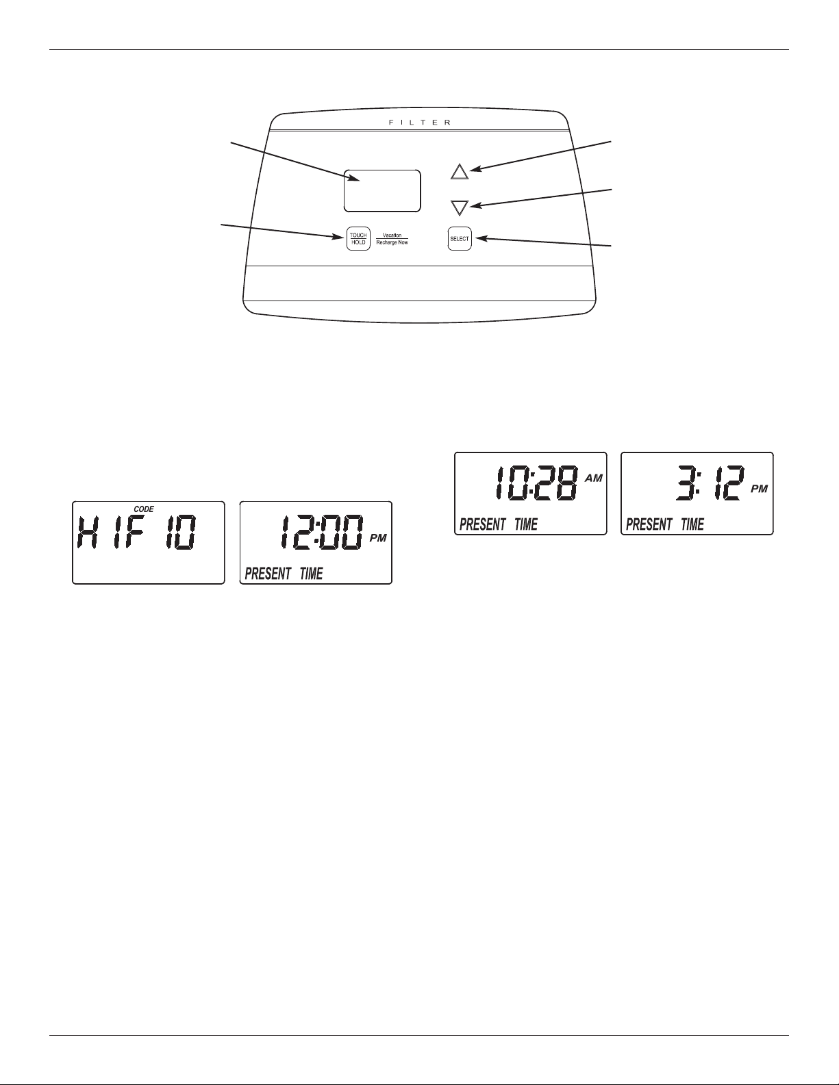
Programming the Electronic Controller
CONTROLLER SETTINGS REQUIRED
upon installation, and after an extended power outage.
When the power supply is plugged into the electrical
outlet, a model code (HIF10) and a test number
(example: J3.8), are briefly shown in the display.
Then the words “PRESENT TIME” appear and 12:00
PM begins to flash.
A. SET PRESENT TIME OF DAY
If the words “PRESENT TIME" do not show in the dis-
play, press the SELECT button several times until
they do.
FIG. 12
FIG. 13
1. Press the r UP or s DOWN buttons to set the
present time. Up moves the display ahead; down
sets the time back. Be sure AM or PM is correct.
NOTE: Press buttons and quickly release to slowly
advance the display. Hold the buttons down
for fast advance.
2. When the correct time is displayed, press the
SELECT button, and the display will change to
show the next setup screen.
FIG. 11
U
P button
DOWN
button
D
isplay
TOUCH/HOLD
button
SELECT
button
11
Programming the Electronic Controller
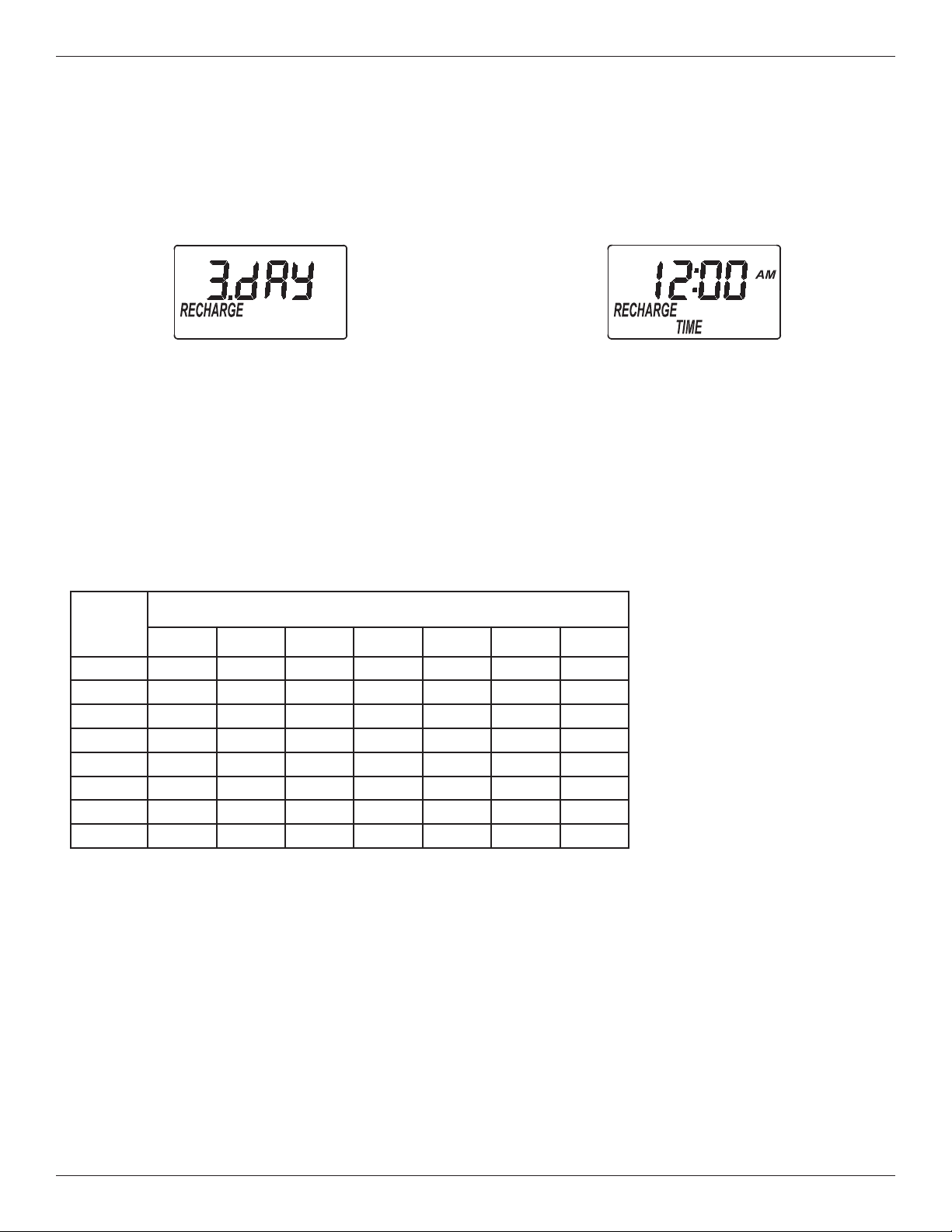
B. SET DAYS BETWEEN RECHARGES
1. If you completed the previous step, the word
“RECHARGE" should show in the display (See
Figure 14). Otherwise, press the SELECT button
several times until it does.
2. The default setting is 3 days. This means that the
filter will recharge every 3 days. See the chart
below to determine the frequency of recharges. To
change the number of days between recharges,
use the r UP or s DOWN buttons to adjust from
1 to 99 days.
3. When the desired number of days is displayed,
press the SELECT button, and the display will
change to show the next setup screen.
FIG. 14
NOTE: If there is an iron bleed or the water supply has high turbidity (sand, silt, sedi-
ments, etc.), set the filter to regenerate more often than the table above shows.
NOTE: In some extreme iron conditions, a fill setting of 2 minutes (3 ounces of
potassium permanganate used), or 3 minutes (4 oz.) could be needed
for each regeneration.
NOTE: If hydrogen sulfide is present, decrease the number of days between
recharges by one or more (to a minimum setting of 1 day between
recharges) until contaminant is removed.
C. SET RECHARGE START TIME
1. If you completed the previous step, the words
“RECHARGE TIME" should show in the display
(See Figure 15). Otherwise, press the SELECT
button several times until they do.
Number
of
People
Iron (parts per million)
2 4 6 8 10 15 20
1 7 days 6 days 5 days 4 days 3 days 3 days 2 days
2 6 days 5 days 3 days 3 days 2 days 1 day 1 day
3 5 days 3 days 2 days 2 days 1 day 1 day 1 day
4 4 days 3 days 2 days 1 day 1 day 1 day 1 day
5 4 days 2 days 1 day 1 day 1 day 1 day 1 day
6 3 days 2 days 1 day 1 day 1 day 1 day 1 day
7 3 days 1 day 1 day 1 day 1 day 1 day 1 day
8 2 days 1 day 1 day 1 day 1 day 1 day 1 day
2. The filter’s default recharge start time is 12:00 AM.
This is normally a time of day when water is not
being used in the household. If you have a water
softener or another filter installed, the recharge
start times should be offset to assure adequate
water flow and pressure. For example, if the water
softener is set to begin recharge at 2:00 AM, set
the filter to start recharge at 12:00 AM, or 4:00 AM.
Use the r UP or s DOWN buttons to adjust the
FIG. 15
SUGGESTED DAYS BETWEEN RECHARGES
recharge start time.
3. When the desired recharge
time is displayed, press
the SELECT button, and
the display will change to
show the normal run (time
of day) display.
12
Controller Features / Options
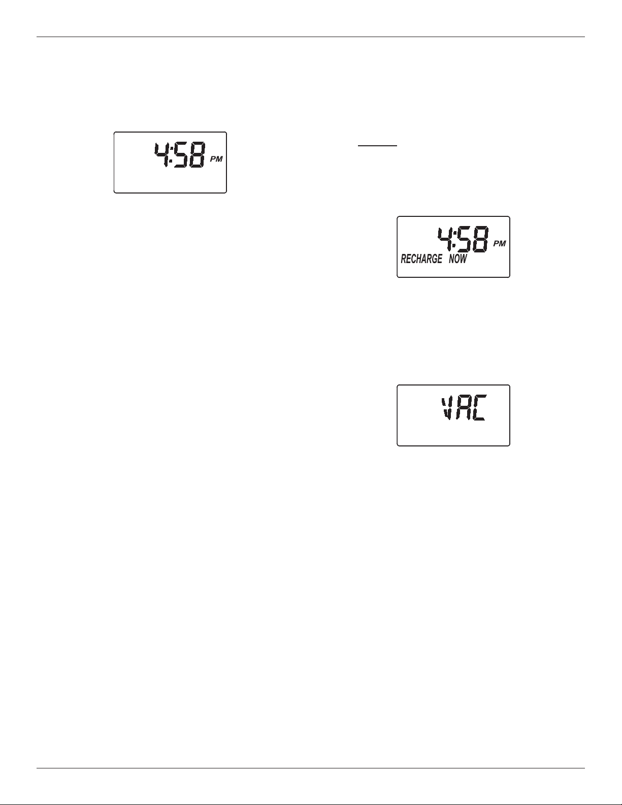
FIG. 16
RECHARGE NOW
For times when you expect to use more water than
usual, it may be desirable to perform a manually initi-
ated recharge. To manually start a recharge cycle,
press and hold the TOUCH/HOLD button for a few
seconds, until “RECHARGE NOW” flashes in the dis-
play. The filter begins an immediate backwash.
Once started, you cannot cancel this recharge. Avoid
using hot water during this time, as the water heater
will refill with unfiltered water.
FIG. 17
VACATION CONTROL
1. Before going on vacation, or other long absence,
press (but do not hold) the TOUCH/HOLD button, so
that “VAC” begins to flash in the display. The timer
continues to keep time, but recharges will not occur,
saving water.
2. When you return, press the TOUCH/HOLD button
again. This cancels the flashing “VAC” and returns
the filter to normal service. You must remember to do
this, or the filter will not recharge.
FIG. 18
NORMAL OPERATION
During normal operation, the present time of day
shows in the display.
POWER OUTAGE MEMORY
If electrical power to the filter’s control is lost, internal
memory will maintain most settings such as the days
between recharge and recharge time. However,
unless the power outage was very brief, the clock’s
present time will need to be reset. During a power
outage, the display will be blank and the filter will not
recharge. When electrical power is restored:
1. Check the display.
2a. If the present time is displayed steadily (not flash-
ing), the controller did not lose time and you do
not need to reset the clock.
2b. If a time is flashing in the display, then the clock
needs to be reset to the correct present time.
See “Set Time of Day” on page 10. The flashing
display is to remind you to reset the clock. If you
do not reset the clock, then recharges will most
likely occur at the wrong time of day.
NOTE: If the filter was recharging when power was
lost, it will finish the cycle when power returns.
13
Controller Features / Options
RECHARGE CYCLE TIME ADJUSTMENTS
The default durations for fill (0 minutes), solution draw
/ rinse (0 minutes), backwash (25 minutes), and fast
rinse ( 5 minutes), are factory set for maximum filter
performance. Use the following procedure to check
for correct cycle times, or to change if desired.
However, only trained technicians should change the
time settings.
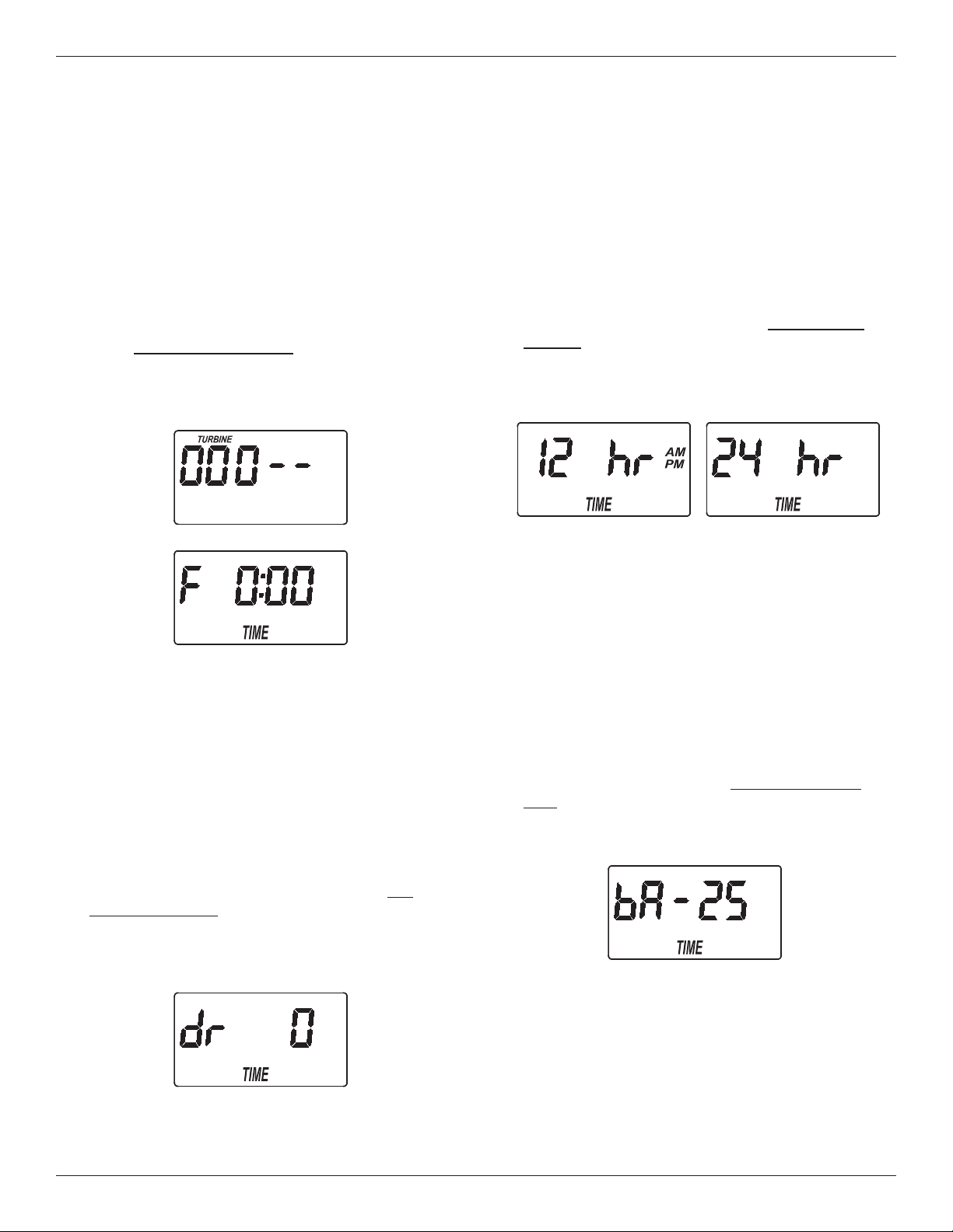
A. ADJUSTABLE FILL TIME
1. Press and hold for 3 seconds the SELECT button,
until the display shows “000 - -“ (See Figure 19),
then press the SELECT button again to display the
fill time adjust screen (See Figure 20).
FIG. 19
2. Use the r UP or s DOWN buttons to adjust fill
time from 0:00 minutes to 99:59 minutes.
3. When the desired fill time is displayed, press the
SELECT button, and the display will change to
show the next cycle time adjust screen.
B. ADJUSTABLE SOLUTION DRAW /
RINSE TIME
1. If you completed the previous step, the solution
draw / rinse time adjust screen should show in the
display (See Figure 21). Otherwise, press and
hold for 3 seconds the SELECT button, until the
display shows “000 - -“, then press the SELECT
button twice to display the solution draw / rinse
time adjust screen.
FIG. 21
2
. Use the
r U
P or
s D
OWN buttons to adjust solu-
tion draw / rinse time from 0 to 255 minutes.
3. When the desired draw time is displayed, press the
SELECT button, and the display will change to
s
how the 12 / 24 hour clock setting screen.
C. 12 OR 24 HOUR CLOCK
1. If you completed the previous step, the 12 / 24 hour
clock setting screen should show in the display
(See Figure 22). Otherwise, press and hold for 3
seconds the SELECT button, until the display
shows “000 - -“, then press the SELECT button
three times to display the 12 / 24 hour clock setting
screen.
2. All time displays are shown in 12 hour (AM/PM)
format at the default setting. If 24 hour time format
is de sired, set to “24 hr” by pressing the r UP
button.
3. Press the SELECT button, and the display will
change to show the next cycle time adjust screen.
D. ADJUSTABLE BACKWASH TIME
1. If you completed the previous step, the backwash
time adjust screen should show in the display (See
Figure 23). Otherwise, press and hold for 3 sec-
onds the SELECT button, until the display shows
“000 - -“, then press the SELECT button four times
to display the backwash time adjust screen.
2. Use the r UP or s DOWN buttons to adjust
backwash time from 0 to 99 minutes.
3. When the desired backwash time is displayed,
press the SELECT button, and the display will
change to show the next cycle time adjust screen.
continued on next page
FIG. 23
FIG. 20
FIG. 22
14
continued from previous page
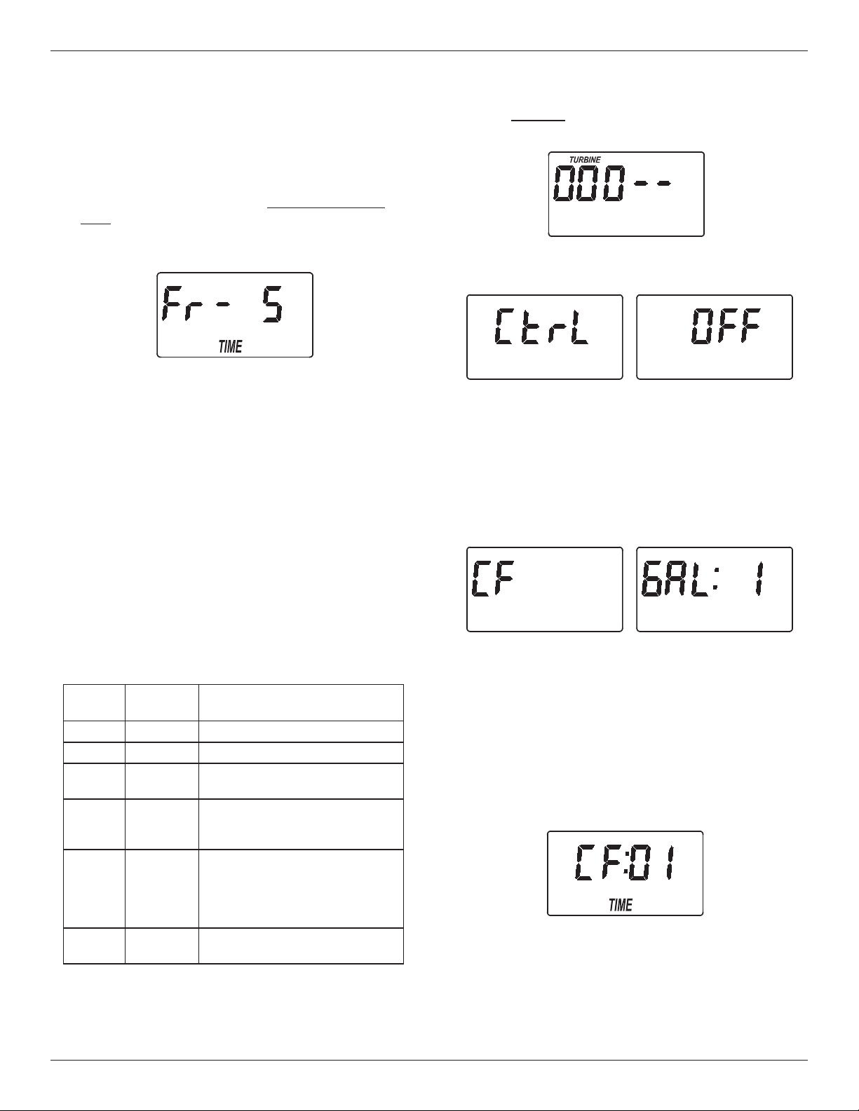
E. ADJUSTABLE FAST RINSE TIME
1. If you completed the previous step, the fast rinse
t
ime adjust screen should show in the display (See
Figure 24). Otherwise, press and hold for 3 sec
-
onds the SELECT button, until the display shows
“000 - -“, then press the SELECT button five times
to display the fast rinse time adjust screen.
Controller Features / Options
1. Press and hold the SELECT button until “000 - -”
s
hows in the display (See Figure 25).
3. Use the
r UP or s DOWN buttons to display the
desired selection, then press the SELECT button.
If you selected anything other than CF, the display
will return to the normal run (time of day) screen.
If setting to CF (Chemical Feeder), there will be
two additional settings to make for operating the
chemical feeder in Steps 4 and 5, below.
2. Use the
r UP or s DOWN buttons to adjust fast
rinse time from 0 to 99 minutes.
3. When the desired fast rinse time is displayed,
press the SELECT button. Press the SELECT but-
ton several times to advance through the remaining
screens and return to the normal run (time of day)
display.
F. AUXILIARY OUTPUT CONTROL
The electronic controller’s auxiliary output may be
used to operate various types of external equipment,
such as a chlorine generator or chemical feeder. It
provides a 24V DC, up to 500 mA, current from termi-
nal J4 on the electronic control board (see Schematic
on page 17). The table below explains the choices
available for when the auxiliary output will be on dur-
ing various portions of the recharge cycle.
FIG. 24
FIG. 26
FIG. 27
FIG. 28
FIG. 25
2. Press the SELECT button six times, until “Ctrl"
flashes in the display (See Figure 26).
* A turbine and turbine cable must be added to the system if auxiliary output selections “FS” or “CF” are to be used.
The default is OFF. If you wish to change to one of
the other selections shown in the table:
4. CHEMICAL FEEDER TRIP VOLUME: If you have
set the auxiliary output control to CF (Chemical
Feeder), you will need to set the volume of water
which must flow past the turbine* before the auxil-
iary output is turned on. With the alternating
screens in Fig. 27 shown, use the r UP or
s DOWN buttons to set the trip volume, in gal-
lons. Then press the SELECT button to display the
screen shown in Fig. 28.
5. CHEMICAL FEEDER TIME: Use the r UP or
s DOWN buttons to set the length of time, in
seconds, that the auxiliary output will be turned on.
Then press the SELECT button to accept and
return to the normal run (time of day) screen.
SELEC-
TION
NAME
AUXILIARY OUTPUT
FUNCTION
OFF Off Remains off indefinitely.
BP Bypass On during the entire recharge.
CL Chlorine
On during the brine draw portion
of the recharge.
FS
Flow
Switch
On when water is flowing past
the turbine*. It will shut off 8
seconds after water flow stops.
CF
Chemical
Feeder
After the set volume of water
has flowed past the turbine*,
turns on for the time set (see
Steps 4 & 5, below, to set vol-
ume and time).
FR
Fast
Rinse
On during the fast rinse por-
tion of the recharge.

15
General Filter Maintenance
ADDING POTASSIUM PERMANGANATE
POWDER TO FEEDER TANK
It is very important to always have some potassium
permanganate powder in the feeder tank. If the filter
goes too long without a regeneration with potassium
permanganate, the filtering mineral will lose its man-
ganese coating. Replacing the filter mineral bed can
be costly. Be sure to check the feeder tank every 2-4
weeks, and stir the potassium permanganate powder
to keep it from solidifying. Refill it with powder if less
than an inch remains. After filling, check the tank
overflow drain hose to be sure it is over the floor drain
(see step 6, page 8).
HOW LONG DOES THE POTASSIUM PERMAN-
GANATE LAST?
Using 2 ounces of powder each regeneration (at 1
minute fill setting), 6 pounds of potassium perman-
ganate powder will last for about 48 regenerations.
Divide 48 by the number of regenerations needed
each week. The answer is the approximate number
of weeks the potassium permanganate should last.
The 2 minute fill setting uses 3 ounces of powder,
and 3 minutes uses 4 ounces.
CLEANING THE NOZZLE & VENTURI
A clean nozzle & venturi (Fig. 29) is needed for the fil-
ter to work properly. The nozzle & venturi creates the
suction to move potassium permanganate solution
from the feeder tank to the mineral tank during regen-
eration. It will not work if it becomes plugged with
sand, silt, dirt, etc. The filter mineral will not be prop-
erly cleaned, and oxidizing capacity restored.
To get access to the nozzle & venturi, remove the fil-
ter’s top cover. Make sure the filter is in “service”
cycle (no water pressure at nozzle and venturi).
Then, while holding the nozzle & venturi housing with
one hand, unscrew the cap. Lift out the screen sup-
port and screen, then the nozzle and venturi. Wash
and rinse the parts in warm water until clean. If need-
ed, use a small brush to remove iron or dirt. Also
check and clean the gasket.
Carefully put all parts back in place in the correct
order. Be sure holes in gasket align with holes in the
housing. Lubricate the o-ring seal with silicone
grease and put in place. Install and tighten the cap,
BY HAND ONLY. DO NOT OVER-TIGHTEN AND
BREAK THE CAP OR HOUSING.
NUMBER OF FULL WEEKS THAT 6 LBS. OF
POTASSIUM PERMANGANATE POWDER LASTS
Number of Regenerations
Each Week
Fill Cycle Minutes
1 2 3
1 48 32 24
2 24 16 12
3 16 10 8
4 12 8 6
5 9 6 4
6 8 5 4
7 6 4 3
Note: The refill container has 6 pounds of potassium
permanganate powder.
PROTECT THE FILTER FROM FREEZING
If the filter is installed where it could freeze (summer
cabin, lake home, etc.), you must drain all water from
it to prevent possible freeze damage.
FIG. 29
Screen
Support
Cap
O-Ring Seal
IMPORTANT: Be sure the
small holes in the gasket
are centered directly over
the small holes in the
nozzle & venturi housing.
Screen
Nozzle &
Venturi
Gasket
Nozzle & Venturi
Housing
*Flow Plug
* Install with numbered side
up and concave side down.

16
Troubleshooting Guide
PROBLEM CAUSE CORRECTION
Filter will not regen-
e
rate
Manual plumbing bypass valve(s) in
b
ypass position.
Refer to figures 3 and 4 on page 6, and posi-
t
ion for filtered water ‘‘service’’.
Power supply unplugged at wall outlet,
fuse blown/circuit breaker popped, circuit
switched off.
Check for loss of power and correct as need-
ed. Reset the timer and use the RECHARGE
NOW feature as described on page 12.
Timer set for vacation (VAC). Press the Touch/Hold button once to return
the filter to service, see page 12.
Timer not programmed for regenerations,
or time too short.
See pages 11 or 13-14 to set.
Error code shows in timer display. See next page.
Backwash flow control, drain hose
restricted or plugged, backwash flow less
than 5 gpm.
Check drain hose. Remove drain elbow on
filter valve to check flow control. See page 22
to check for correct assembly and orientation.
Backwash flow should be 5 gpm or higher.
Nozzle assembly dirty. Follow instructions on page 15 to clean.
Low water pressure
at house faucets
Well pump pressure switch set too low. Adjust to a minimum of 20 psi.
More frequent regeneration needed to
keep filter mineral clean.
See page 11 to set days between recharges.
Filtered water con-
tains iron, sediment,
dirt, etc.
See all conditions above.
Too infrequent regenerations pro-
grammed, or fill time setting too short.
See page 11 to set days between recharges,
see page 13 to adjust fill time.
Feeder tank out of potassium perman-
ganate powder.
Follow instructions on page 15 to refill.
Hot water used while filter regenerating. The water heater will refill with unfiltered
bypass water. See page 11 to set recharge
start time.
Possible increase in supply water iron
content (common with some well water
supplies).
Obtain a new water analysis and adjust the
regeneration schedule and/or fill cycle time.
Leaking faucet or toilet valve. A small leak can waste hundreds of gallons of
water in a few days time. Fix all plumbing
leaks and always fully close faucets.
CHECKLIST BEFORE YOU CALL FOR SERVICE
17
Troubleshooting
AUTOMATIC ELECTRONIC DIAGNOSTICS
This filter has a self-diagnostic function for the electri-
cal system. The computer monitors electronic com-
ponents and circuits for correct operation. If a mal-
function occurs, an error code appears in the display.
The chart above shows the error codes that could
appear, and the possible malfunctions for each code.
While an error code appears in the display, all buttons
are inoperable except the SELECT button. SELECT
remains operational so the service person can per-
form the Manual Initiated Electronic Diagnostics, see
below, to further isolate the problem.
FIG. 31
Code Possible Problems
Err01 Motor, Valve Position Switch
Err03 Motor, Valve Position Switch, Wire Harness
Err04 Valve Position Switch
Err05 Electronic Control Board (PWA)
TO REMOVE AN ERROR CODE:
1. Unplug the power supply.
2. Correct the problem.
3. Plug the power supply back in.
4. Wait for at least 8 minutes while the timer operates
the valve through an entire cycle. The error code
will return if the problem was not corrected.
RESETTING TO FACTORY DEFAULTS
To reset the electronic controller to its factory default
for all settings (time, days between recharges, etc.):
1. Press the SELECT button and hold it until the dis-
play changes twice to show “CODE” and the flash-
ing model code.
2. Press the r UP button (a few times, if necessary)
to display a flashing “SoS”.
3. Press the SELECT button, and the electronic con-
troller will restart.
4. Set the present time, days between recharges,
etc., as described on pages 10 & 11.
FIG. 32
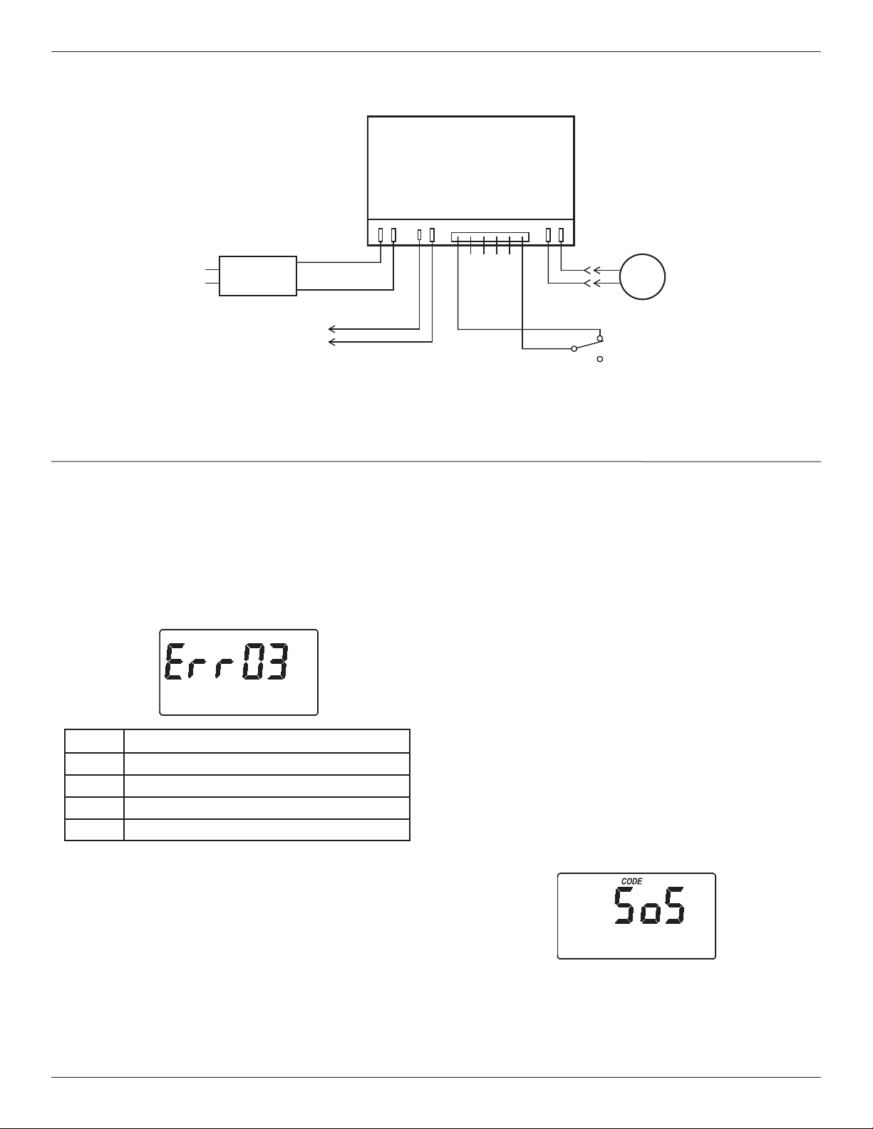
WIRING SCHEMATIC
FIG. 30
NO
Valve
Motor
Position
Switch
NC
Power Supply
B
ack of Electronic Controller
(PWA)
Power
In
Pos./Turbine
Motor
24V DC
Auxiliary Output
J4
24V DC
120V AC
60 Hz
C
org
grn
Schematic
18
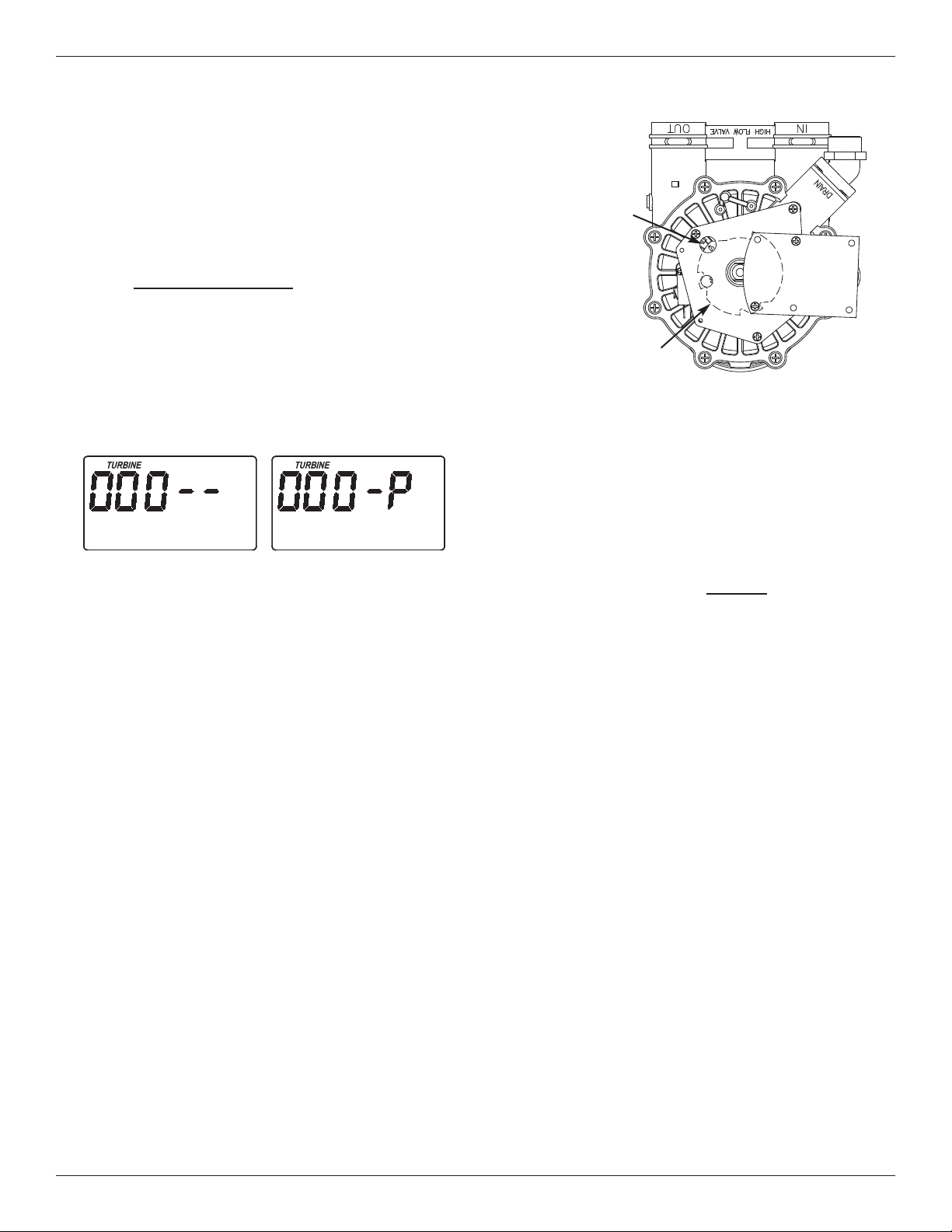
Position markers
(valve in service)
CAM
MOTOR
FIG. 34
Troubleshooting
MANUALLY INITIATED ELECTRONIC
DIAGNOSTICS
U
se the following procedures to advance the filter
through the recharge cycles to check operation.
Remove the top cover faceplate assembly by unlock-
ing the tabs and lifting, to observe cam and switch
operation during valve rotation (See Figure 34).
1. Press and hold for 3 seconds
the SELECT button,
until one of the screens shown in Figure 33 is dis-
played. If the valve is in service, fill, solution draw /
brining, backwash or fast rinse position (observe
markings on the valve cam), the display should
show “000 - -”, meaning the position switch is
open. When the valve is moving, the display
should show “000 - P”, meaning that the position
switch is closed.
2. Only for filter systems modified by adding a
turbine and turbine cable:
If a turbine has been installed in your filter’s valve
outlet port, the first 3 digits of the display in Figure
33 should count upward whenever water is flowing
through the system.
3. Use the TOUCH/HOLD button to manually advance
the valve into each position and check correct switch
operation.
4. While in this diagnostic screen, the following infor-
mation is available and may be beneficial for vari-
ous reasons. This information is retained by the
computer from the first time electrical power is
applied to the electronic controller.
a. Press the r UP button to display the number of
days this electronic control has had electrical
power applied.
b. Press the s DOWN button to display the num-
ber of recharges initiated by this electronic con-
trol since the model code number was entered.
5. Press the SELECT button and hold in for 3 sec-
onds until the model code shows in the display.
This code identifies the filter model. If the wrong
number shows (see table on page 4), the filter will
operate on incorrect configuration data.
6. To change the code number - Press the r UP or
s DOWN button until the correct code shows.
7. To return to the present time display, press the
SELECT button. If the model code was
changed, make all timer settings.
NOTE: If the electronic control is left in a diagnostic
display (or a flashing display when setting
times or hardness), present time automatically
returns if a button is not pressed within 4 min-
utes.
FIG. 33
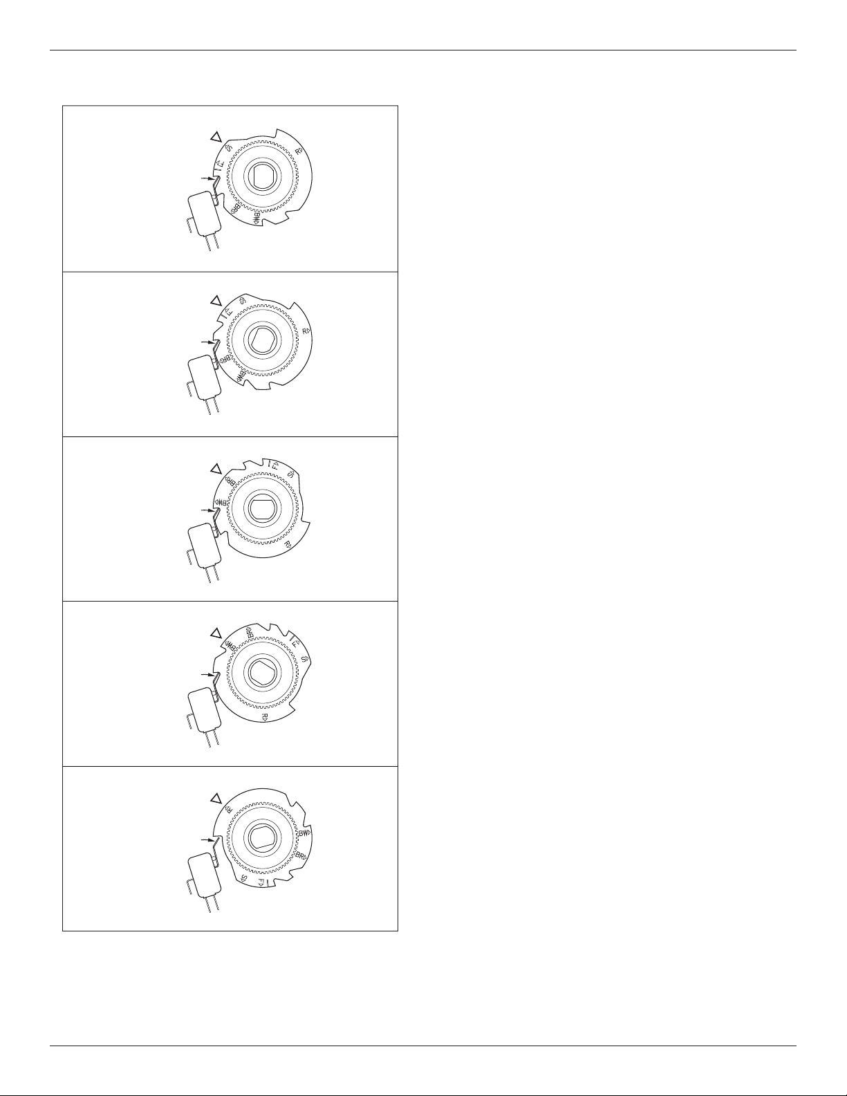
19
Valve Cam
FIG. 35
Position Switch
S
SERVICE
Valve Cam
FIG. 36
BR
FILL
F
BRINE DRAW
Position Switch
Valve Cam
FIG. 37
Position Switch
Valve Cam
FIG. 38
BW
BACKWASH
FAST RINSE
Position Switch
Valve Cam
FIG. 39
Position Switch
R
Troubleshooting
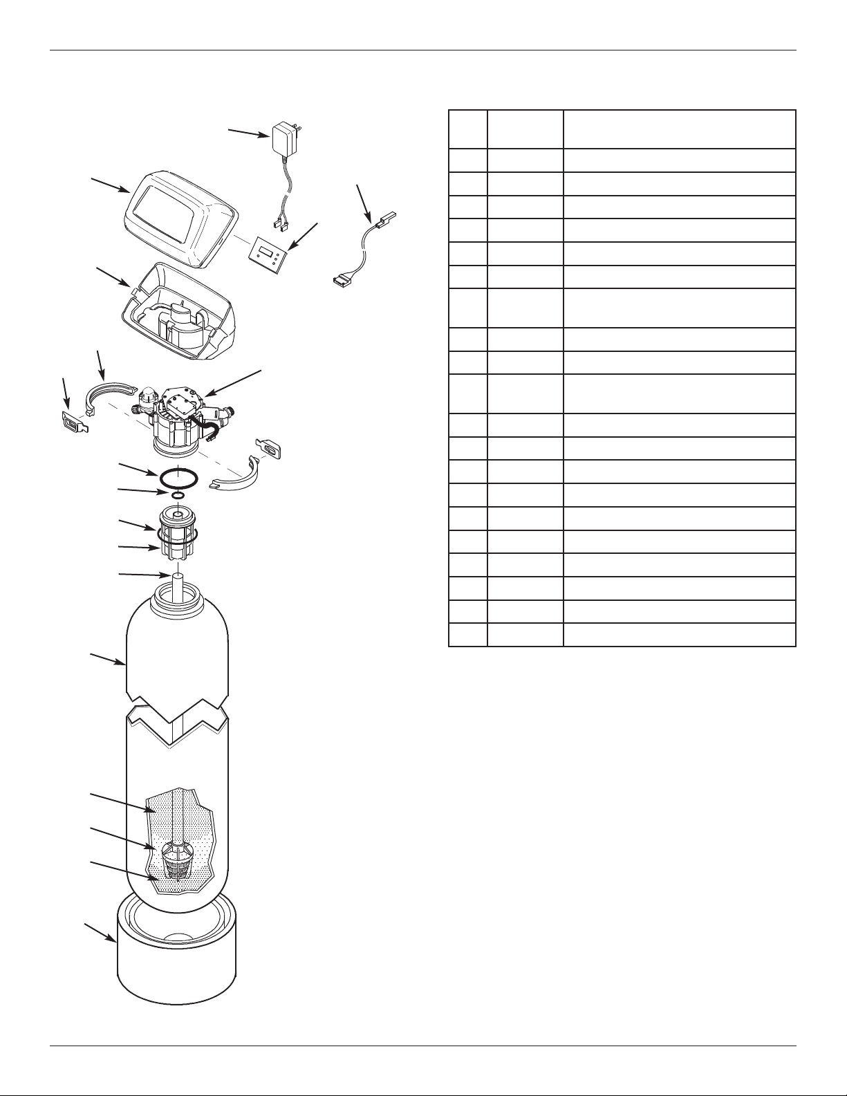
20
Key
No.
Part No. Description
1 7
351054
P
ower Supply, 24V DC
2 7259927 Wire Harness
3 7366677 Repl. Timer (PWA)
4 7260554 Top Cover (order decal below)
¢
7285279 Decal, Filter
5 7189449 Bottom Cover
– 7331177
Tank Neck Clamp Kit
(includes Key Nos. 6 & 7)
6
á
Clamp Section (2 req.)
7
á
Retainer Clip (2 req.)
– 7112963
Distributor O-Ring Kit
(includes Key Nos. 8-10)
8
á
O-Ring, 2-7/8” x 3-1/4”
9
á
O-Ring, 13/16” x 1-1/16”
10
á
O-Ring, 2-3/4” x 3”
11 7088855 Top Distributor
12 7105047 Repl. Bottom Distributor
13 7092202 Mineral Tank, 10” x 47”
14 7331680 Greensand Plus, 1 cu. ft.
15 0501783 Filter Sand, 10 lbs.
16 7124415 Gravel, 17 lbs.
17 7302039 Tank Foot, 10” Tank
¢ Not illustrated.
Manufactured and warranted by
Water Channel Partners
1890 Woodlane Drive
Woodbury, MN 55125
Filter Assembly Parts
1
2
3
4
5
7
6
8
9
10
11
12
13
17
Valve Assembly
See Pages 22 & 23
for parts
14
15
16
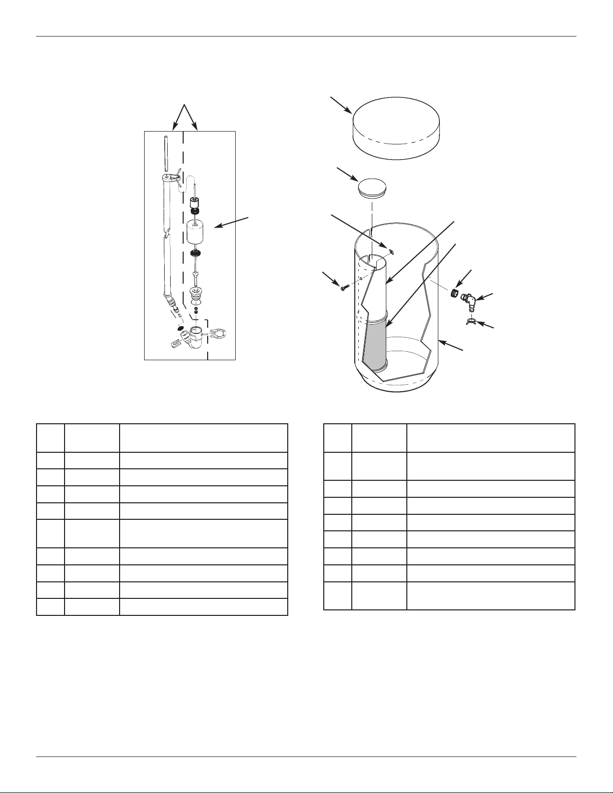
21
Feeder Assembly Parts
Key
No.
Part No. Description
–
7331258
Overflow Hose Adaptor Kit
(includes Key Nos. 33-35)
33
á
Grommet
34
á
Drain Hose Adaptor
35
á
Hose Clamp
36 7182421 Feeder Tank
¢
7161807 Drain Tubing, 5/16” x 20 ft.
¢
7161768 Drain Tubing, 5/16” x 100 ft.
¢
7317424
Potassium Permanganate Powder,
2 lbs.
¢ Not illustrated.
Key
No.
Part No. Description
25 7310155 Brine Valve Assembly
26 7289710 Float, Stem & Guide Assembly
27 7071133 Feeder Tank Cover
28 0500283 Cover, Brinewell
–
7331648
Brinewell Mounting Hardware Kit
(includes Key Nos. 29 & 30)
29
á
Wing Nut, 1/4-20
30
á
Screw, 1/4-20 x 15.9 mm
31 7326928 Brinewell
32 7182390 Screen, Brinewell
25
2
7
28
26
29
30
31
32
33
34
35
36
22
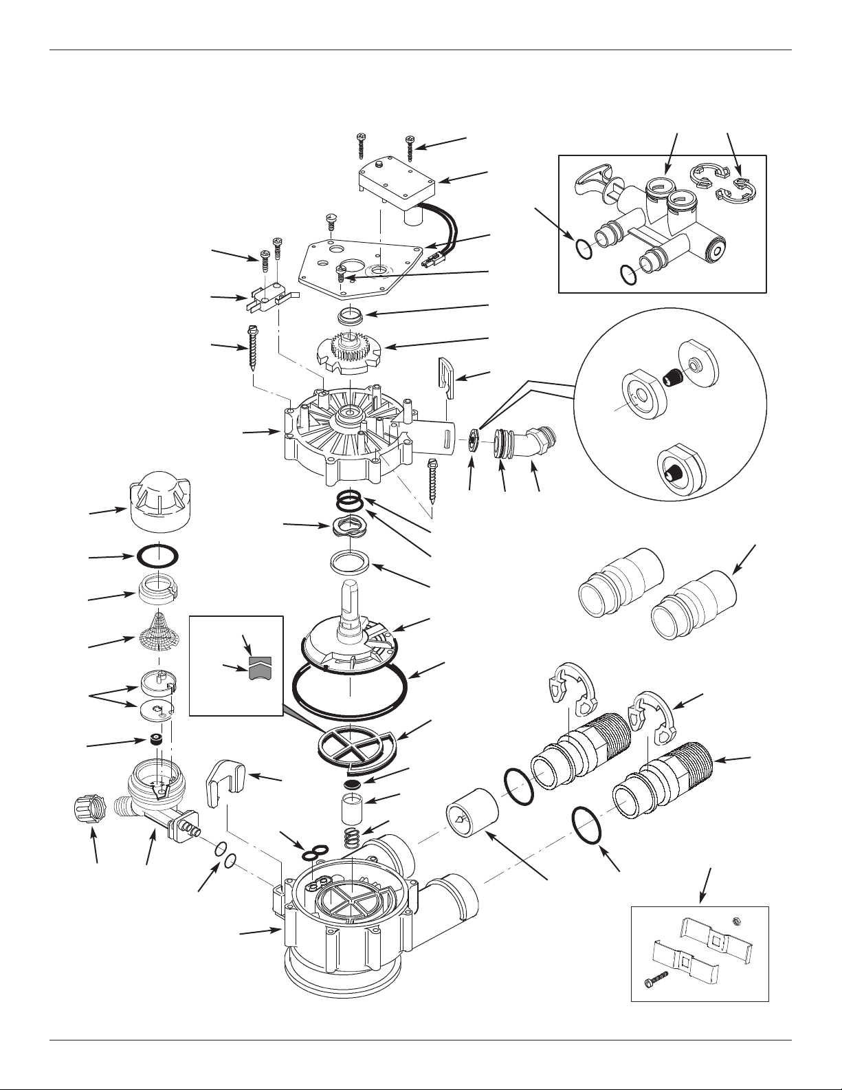
Valve Exploded View
Wear Strip
Seal
Cross-section
View
5
2
50
53
54
55
51
56
57
58
59
60
61
66
67
85
62
63
64
68
69
65
74
70
90
72
70
71
72
73
75
76
78
86
87
88
89
92
Flow Plug
Assembly
Assembled
View
77
84
83
82
81
80
79
91

23
Valve Parts List
Key
No.
Part No. Description
– 7384691
Motor, Cam & Gear Kit, 1”
(includes Key Nos. 50-52)
50
á
Motor
51
á
Cam & Gear
52 7224087 Screw, #8-32 x 1” (2 req.)
53 7231393 Motor Plate
54 0900857 Screw, #6-20 x 3/8” (3 req.)
55 7171250 Bearing
– 7331711
Drain Hose Adaptor Kit
(includes Key Nos. 56-59)
56
á
Clip, Drain
57
á
Drain Hose Adaptor
58
á
O-Ring, 15/16” x 1-3/16”
59
á
Flow Plug, 5.0 gpm
– 7185487 Seal Kit (includes Key Nos. 60-65)
60
á
O-Ring, 5/8” x 13/16”
61
á
O-Ring, 1-1/8” x 1-1/2”
62
á
O-Ring, 4-1/2” x 4-7/8”
63
á
Rotor Seal
64
á
Seal
65
á
Seal, Nozzle & Venturi
66 7174313 Bearing, Wave Washer
67 7185500 Rotor & Disc
– 7342712
Drain Plug Kit, 1”
(includes Key Nos. 64, 68 & 69)
68
á
Plug, Drain Seal
69
á
Spring
70
7089306 Clip, 1”, single (2 req.)
7336428 Clip, 1”, pack of 20
71
7271204 Installation Adaptor, 1”, single
7336614 Installation Adaptor, 1”, pack of 10
Key
No.
Part No. Description
72
7311127
O-Ring, 1-1/16” x 1-5/16”, single
(2 req.)
7336410 O-Ring, 1-1/16” x 1-5/16”, pack of 20
73 7078240 Support
74 7081201 Retainer
75 7171145 Valve Body
76 7342649 O-Ring, 1/4” x 3/8”, pack of 2
77 1202600 Nut - Ferrule
– 7085247
Nozzle & Venturi Assembly
(includes Key Nos. 78-84)
78 7081104 Housing, Nozzle & Venturi
79 1148800 Flow Plug, .3 gpm
80
7114533 Nozzle & Venturi Kit w/Gasket
7204362 Gasket only, single
7336486 Gasket only, pack of 20
81 7146043 Screen
82 7167659 Screen Support
83
7170262 O-Ring, 1-1/8” x 1-3/8”, single
7336436 O-Ring, 1-1/8” x 1-3/8”, pack of 20
84 7199729 Cap
85 7175199 Wave Washer
86 7171161 Valve Cover
87 7342681 Screw, #10 x 2-5/8”, pack of 8
88 7305150 Switch
89 7140738 Screw, #4-24 x 3/4” (2 req.)
90 7214383
Bypass Valve Assembly, 1”,
including 2 ea. Clips & O-Rings
(See Key Nos. 70 & 72)
91 7104546
Adaptor, PVC (2 req.) Ù
92 7248706
Ground Clamp Kit Ù
Manufactured and warranted by
Water Channel Partners
1890 Woodlane Drive
Woodbury, MN 55125
Ù Not included with the system.