ELECTRONIC CONTROL BOARD (PWA) REPLACEMENT
7366716 (Rev. A 6/12/17)
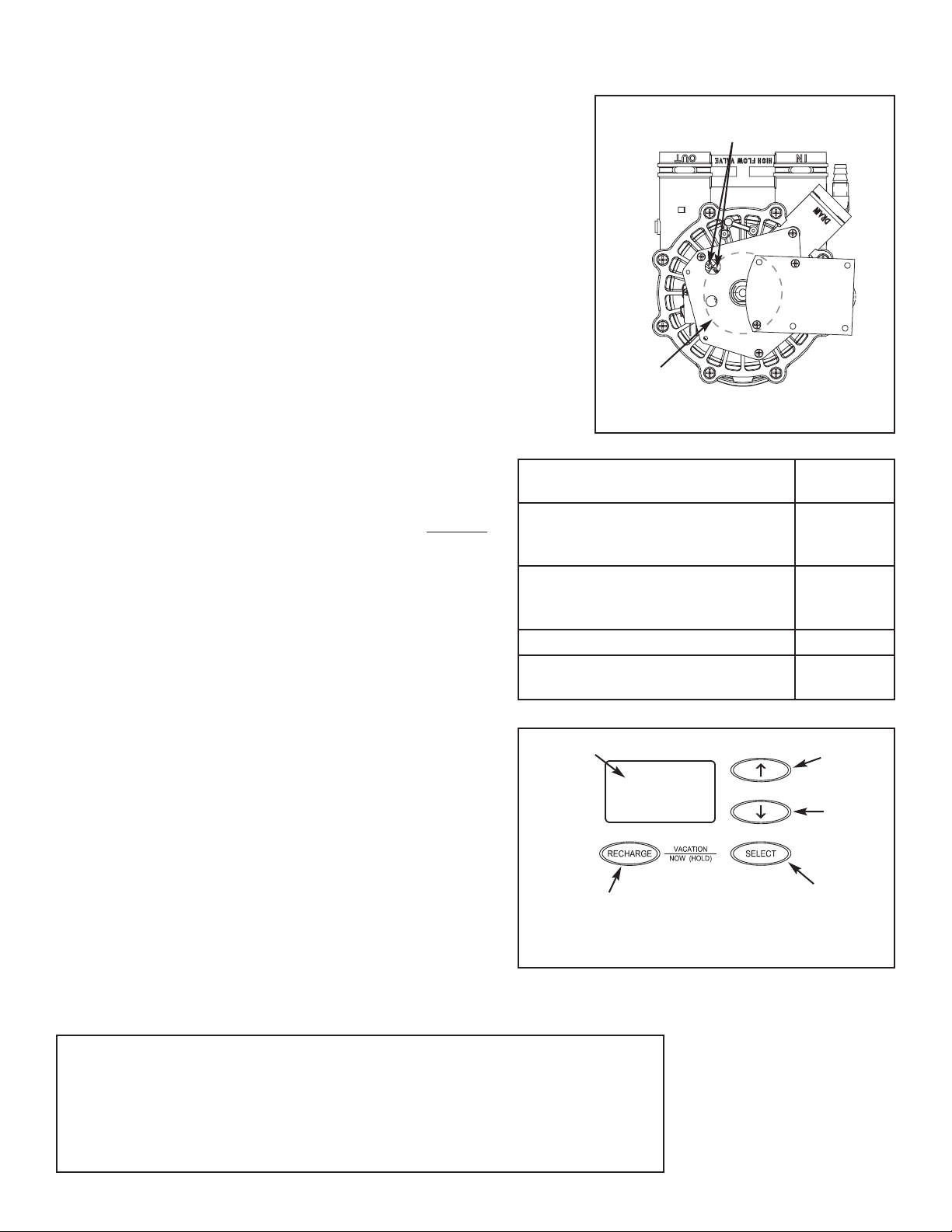
Position markers
(valve in service)
CAM
MOTOR
Figure 1
Water Filter Models
Model Code
to Set
ETF AIV10, ETF AIV12, ETF EIV10,
ETF EIV12, NSAIV-10, NSAIV-12,
NSEIV-10
HAAIF
ETF AIIF-115, ETF AIIF-220,
ETF AIIF10, NS AIIFSS-110,
NS AIIFSS-220, NS AIIF2
HAIIF
ETF2100-IF10, NSIFPPA, AIF10 HIF10
Universal Filter (12”) w/Brine Tank or
Potassium Permanganate Feeder
HIF12
IMPORTANT: BE SURE THE VALVE CAM INDICATES ``SERVICE''
POSITION (See Figure 1) WHEN REPLACING THE ELECTRONIC
CONTROL BOARD (PWA), TO ASSURE BOTH VALVE AND PWA ARE
ORIENTED, OR TIMED, TO THE SAME CYCLE. If the valve is not in
S
ervice position, see step 13 below.
N
OTE: When installing the electronic control board (PWA) on the face-
plate, use care not to twist the circuit board, or force it onto the mounting
pegs. Twisting could damage the printed circuits, or break the LED glass.
Notes for Air Inject Filters:
If your system includes AC solenoid valve P/N 7287645 (valve coil will be pink),
you must replace it with DC solenoid valve P/N 7322699 when replacing the PWA.
If your system includes relay box P/N 7276050 (P/N is printed on the relay box),
you must replace it with relay box P/N 7322681 when replacing the PWA.
1. Unplug the system’s power supply.
2. Remove the system’s top cover to expose the valve.
3. Unplug the wiring connections from the back of the old
Electronic Control Board.
4. Carefully remove the old board by unsnapping it from its
retainer tabs.
5. Carefully snap the new Electronic Control Board into the
retainer tabs.
6. Reconnect the wiring to the new board.
7. Plug the power supply into the electrical outlet. A number
shows in the dsiplay for a few seconds, followed by
flashing “- - - - -”.
NOTE: If “- - - - -” is not flashing in the display, press and hold
the SELECT button until a model code appears.
8. Use the á UP or â DOWN buttons to set the correct
model code for your system (see table at right).
9. With the correct model code displayed, press the SELECT
button. The electronic controller will restart, briefly display-
ing the model code you set.
10. Press the á UP or â DOWN buttons to set the present
time. Up moves the display ahead; down sets the time
back. Be sure AM or PM is correct.
NOTE: Press buttons and quickly release to slowly advance
the display. Hold buttons down for fast advance.
11. Press the SELECT button a few times, until the time
appears on the display, but is not flashing.
12. Program additional water filter features, following instruc-
tions in your owner’s manual.
13. If the valve is not in Service position, press the
RECHARGE (or TOUCH/HOLD) button and hold for 3
seconds to start a recharge cycle. The filter cycles
through the recharge positions during the next 30-90
minutes. After this the electronic controller and valve are
properly oriented together.
NOTE: To save time, use the “manual advance” procedures
to properly time and check operation. See “Trouble -
shooting” section of the manual.
Figure 2
UP
button
DOWN
button
SELECT
button
Display
RECHARGE
button