Loading ...
Loading ...
Loading ...
6 WWW.SENIXTOOLS.COM
ASSEMBLY
INCLUDED PARTS
1. Remove the screw from cutting head guard.
2. Insert the left tab into the slot on the cutting head
guard.
3. Align the screw hole in the mounting bracket with the
screw hole into the cutting head guard.
4. Tighten the screw through the mounting bracket and
into the cutting head guard with the provided screw
driver.
1. Turn the knob counter clockwise to loosen the
coupler.
2. Press and hold the release button.
3. Pull the attachment straight out of the coupler.
The attachment connects to the power head by means
of a coupler device.
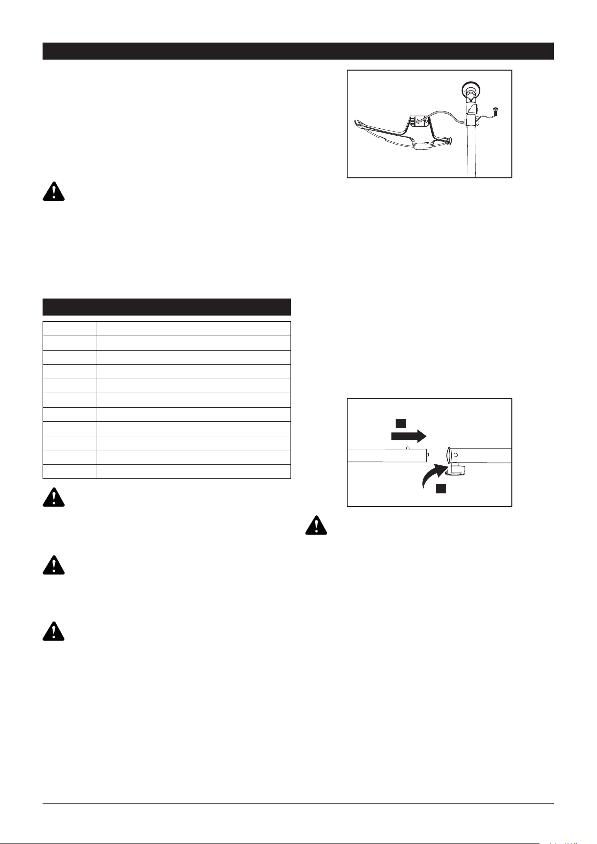
1.Stop the engine and disconnect the spark plug wire.
2.Turn the knob counterclockwise to loosen the coupler
of the power head shaft and remove the end cap
from the attachment (1).
3.Insert while rotating the lower shaft into the coupler
until the button locks into the positioning hole (the
xing hole is opposite the knob).
NOTE: If the button does not release completely in the
positioning hole, the shafts are not locked into place.
Slightly rotate from side to side until the button is locked
into place.
4.Turn the knob (2) clockwise to tighten the coupler.
This product requires assembly. Carefully remove the
product and any accessories from the box. Make sure
that all items listed in the packing list are included.
Inspect the product carefully to make sure no breakage
or damage occurred during shipping.
Do not discard the packing material until you have
carefully inspected and satisfactorily operated the
product. If any parts are damaged or missing, please
call 1-800-261-3981 for assistance.
Do not use this product if any parts on the packing
list are already assembled to your product when you
unpack it. Parts on this list are not assembled to the
product by the manufacturer and require customer
installation. Use of a product that may have been
improperly assembled could result in serious personal
injury.
To prevent an accidental start that could cause serious
personal injury, always disconnect the engine spark
plug wire from the spark plug when assembling parts.
The cutting line spool must be xed rmly with the hub.
Failure to x the cutting line spool with the hub can
result in serious personal injury.
Make sure the knob is fully tightened before operating
the unit, check it periodically for tightness during use to
avoid serious personal injury.
Unless specied otherwise, the release button should
be snaped into the positioning hole only. Using the
wrong hole could lead to personal injury or damage to
the unit.
Never install, remove, or adjust any attachments while
power head is running. Failure to stop the engine can
cause serious personal injury.
WARNING:
WARNING:
WARNING:
WARNING:
WARNING:
Quantity Item
1 Fast Start Guide
1 Operator’s Manual
1 Handle and mounting hardware
1 Cutting line spool
1 Fixed line head
1 Cutting head shield and mounting screw
1
Screw driver
1 Spark plug wrench
1
60 ml bottle (empty)
1 Warranty statement
INSTALL CUTTING HEAD GUARD
REMOVING ATTACHMENT
CONNECT THE UPPER AND LOWER
SHAFT
1.
2.
Loading ...
Loading ...
Loading ...