
Loading ...
Loading ...
Loading ...
English
7
1. Using a 5mm hex wrench, loosen rear pivot bracket fasteners
38
just enough to allow the
bracket to move side-to-side.
2. Adjust the bracket until the blade is parallel to the miter gaugetrack
23
.
3. Tighten the rear pivot bracket fasteners to 110–120 in-lbs (12.5–13.6 Nm).
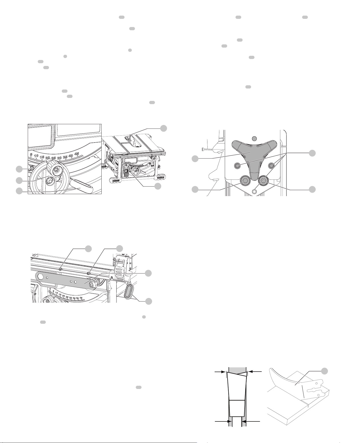
Bevel Stop and Pointer Adjustment (Fig.K)
1. Raise the blade fully by rotating the blade height adjustment wheel
6
clockwise until itstops.
2. Unlock the bevel lock lever
7
by pushing it up and to the right. Loosen the bevel
stopscrew
39
.
3. Place a square
41
flat against the table top and against the blade between teeth, as shown
in FigureM. Ensure the bevel lock lever is in its unlocked, or up,position.
4. Using the bevel lock lever, adjust the bevel angle until it is flat against thesquare.
5. Tighten the bevel lock lever by pushing itdown.
6. Turn the bevel stop screw
39
to rotate the cam until it firmly contacts the bearing block.
Tighten the bevel stop screw
39
.
7. Check the bevel angle scale. If the pointer does not read 0°, loosen pointer screw
40
and
move the pointer so it reads correctly. Retighten the pointerscrew.
8. Repeat at 45°, but do not adjustpointer.
41
40
39
6
7
Fig. K
Fence Alignment Adjustment (Fig.F, L)
(Blade Parallel to Fence)
If you experience fence alignment problems and want to correct an out of parallel alignment
between the fence and the blade, be sure to check the alignment of the blade to the miter slot
first. After confirming that those elements are aligned, proceed with alignment of the blade to
the fence using the following procedure:
Position 2
Position 1
Fig. L
31
31
5
19
Position 1 Fence Alignment
1. Install the fence in position 1 (Refer to Figure F) and unlock the rail lock lever
5
. Locate both
locator pins
31
that support the fence on the front and rearrails.
2. Loosen the rear locator pin screw and adjust the alignment of the fence in the groove until
the fence face is parallel to the blade. Make sure you measure from the fence face to the front
and back of the blade to ensurealignment.
3. Tighten the locator pinscrew.
4. Check rip scale pointeradjustment.
nOTE: Follow the Position 1 Fence Alignment instructions for aligning the fence on the left of
theblade.
Position 2 Fence Alignment
1. To align position 2 fence locator pins, ensure position 1 pins have been aligned, refer to
Position 1 FenceAlignment.
2. Loosen the position 2 locator pins, then using holes in the blade wrench
19
as a guide for
positioning, align the pins (Fig.L).
3. Tighten the locator pins (front and rear).
Aligning Riving Knife to Blade (Fig.O)
1. Remove the throat plate. Refer to Removing the Throat Plate underAssembly.
2. Raise the blade to full depth of cut and 0° bevelangle.
3. Locate the three small set screws
42
adjacent to the riving knife lock knob
30
. These screws
will be used to adjust the riving knifeposition.
4. Lay a straight edge on the table against two blade tips. The riving knife should not touch the
straightedge.
5. Loosen the two larger lock screws
43
.
6. Use the small set screws
42
to adjust the riving knife position. Lay the straight edge on the
opposite side of the blade and repeat adjustments asneeded.
7. Lightly tighten the two larger lock screws
43
.
8. Place a square flat against the riving knife to verify the riving knife is vertical and in-line with
theblade.
9. If needed, use the set screws to bring the riving knife vertical with thesquare.
10. Repeat step 4 to verify position of rivingknife. Repeat 5 through 9 ifnecessary.
11. Fully tighten the two larger lock screws
43
.
WARNING: Before connecting the table saw to the power source or operating the saw,
always inspect the guard assembly and riving knife for proper alignment and clearance with
saw blade. Check alignment after each change of bevel angle. If any dragging or binding
of the material is encountered as it reaches the riving knife, turn unit off and disconnect
machine from power source. Ensure proper riving knife alignment before attempting
anothercut.
Fig. M
42
4343
30
Saw Blades
WARNING: Riving knives must be matched to saw blade dimensions in order to function
effectively. Refer to splitter and Riving Knifeselection. Use only 8-1/4" (210mm)
diameter blades with this tablesaw.
• The saw blade furnished with your new saw is a 8-1/4" (210mm) combination blade,
used for crosscutting (across the grain) and ripping (with the grain) through the
material. The center hole to fit on the arbor is 5/8" (16mm) diameter. This blade will
produce a good quality cut for mostapplications.
• There are many types of blades available to do specific and special jobs such as cross cut
only, rip only, hollow ground, thin plywood, paneling,etc.
• Use only saw blades designed for maximum safe operating speeds of 6000RPM
orgreater.
• Saw blades should always be kept sharp. It is recommended that you locate a reputable
sharpening service to sharpen your blades whenneeded.
• Never stack blades on top of one another to store. Place material such as cardboard
between them to keep the blades from coming in contact with oneanother.
WARNING: To reduce the risk of injury, abrasive wheels or blades (including diamond)
should not be used on thissaw.
Splitter and Riving Knife Selection (Fig.N)
WARNING: To minimize the risk of kickback and to ensure proper cutting, the splitter and
riving knife must be the proper thickness for the bladeused.
The splitter and riving knife supplied with this table saw is the correct size for the blade supplied
with thesaw.
If a different blade is used, check the blade body (plate) thickness and the blade kerf (cutting)
width marked on the blade or on the blade packaging. The splitter and riving knife thickness
must be greater than the body thickness and less than the kerf width as shown in FigureN.
Riving knife thickness
Kerf width (width of cut
made by the blade)
Body (or plate)
thickness of the blade
Fig. N
21
Loading ...
Loading ...
Loading ...