
Loading ...
Loading ...
Loading ...
English
6
nOTE: This saw is fully and accurately adjusted at the factory at the time of manufacture. If
readjustment due to shipping and handling or any other reason is required, follow the sections
below to adjust thissaw.
Once made, these adjustments should remain accurate. Take a little time now to follow these
directions carefully to maintain the accuracy of which this saw iscapable.
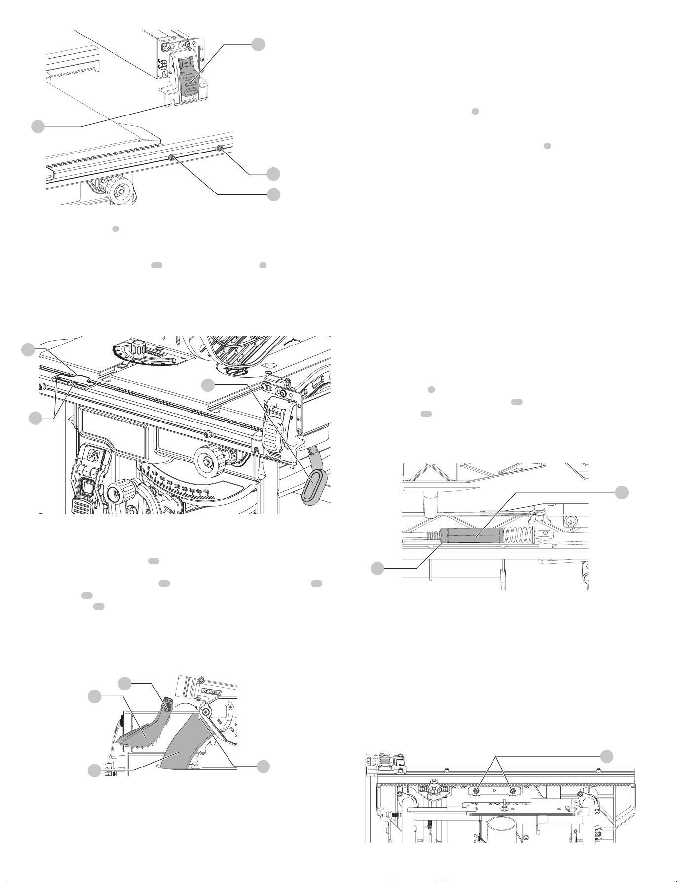
Rail Lock Adjustment (Fig.G, I)
(Tightening Fence Clamping System)
1. Lock the rail lock lever
5
.
2. On the underside of the saw, loosen the jam nut
36
.
3. Tighten the hex rod
37
until the spring on the locking system is more compressed, (not fully
compressed) creating the desired tension on the rail lock lever. Retighten the jam nut against
the hexrod.
4. Check that the fence does not move when the lock lever is engaged. If the fence is still loose,
tighten the springfurther.
Fig. I
36
37
Rip Scale Adjustment
See Adjusting the Rip Scale underAssembly.
Adjusting Blade Alignment (Fig.A, J)
(Blade Parallel to Miter slot)
WARNING: Cut Hazard. Check the blade at 0˚ and 45˚ to make sure blade does not hit the
throat plate, causing personalinjury.
If the blade appears to be out of alignment with the miter slot on the table top, it will require
calibration for alignment. To realign the blade and miter slot, use the following procedure:
WARNING: To reduce the risk of serious personal injury, turn unit off and disconnect
it from power source before making any adjustments or removing/installing
attachments oraccessories. An accidental start-up can causeinjury.
38
Fig. J
ASSEMBLY AND ADJUSTMENTS
WARNING: To reduce the risk of serious personal injury, turn unit off and disconnect
it from power source before making any adjustments or removing/installing
attachments or accessories. An accidental start-up can causeinjury.
31
31
17
32
Fig. F
Position 1
Position 2
Adjusting the Rip Scale (Fig. G)
1. Unlock the rail lock lever
5
.
2. Set the blade at 0° bevel and move the fence in until it touches theblade.
3. Lock the rail locklever.
4. Loosen the rip scale indicator screws
33
and set the rip scale indicator
3
to read zero (0)
Retighten the rip scale indicator screws. The yellow rip scale (top) reads correctly only when
the fence is mounted on the right side of the blade and is in position 1 [for 0 to 20" (508mm)
ripping] [not the 24.5" (622mm) rip position]. The white scale (bottom) reads correctly only
when the fence is mounted on the right side of the blade and in position 2 [for 4" (102mm)
to 24.5" (622mm) ripping].
33
5
Fig. G
3
Anti-Kickback Assembly (Fig. H)
WARNING: To reduce the risk of serious personal injury, the anti-kickback assembly must be
in place for all possiblecuts.
1. Remove the anti-kickback assembly
12
from the storage position by depressing the stem.
Refer toStorage.
2. Locate the anti-kickback mounting slot
34
at the top rear of the blade guard assembly
11
.
3. Align the stem
35
with the mounting slot. Depress the stem and push down on the anti-
kickback assembly
12
until it snaps and locks intoplace.
4. To remove the anti-kickback assembly, depress the stem and pull up and out of the
mountingslot.
With power disconnected, operate the blade tilt and height adjustments through the extremes
of travel and ensure the blade guard assembly clears the blade in all operations and that the anti-
kickback assembly is functioning.
Fig. H
12
34
11
35
Bench Mounting (Fig. A)
nOTE: A portable table saw stand is designed for use with this saw and is available at a local
DEWALT
dealer or service center at extracost.
WARNING: To reduce the risk of serious personal injury, turn unit off and disconnect
it from power source before making any adjustments or removing/installing
attachments oraccessories. An accidental start-up can causeinjury.
WARNING: To reduce the risk of injury, the saw must be secured to prevent unintended
movement duringuse.
The table saw must be securely mounted on a stand, workbench or other rigid and stable support
so that the saw does not move while cutting and cannot be overturned by large overhanging
pieces of material. Four mounting holes
9
are provided in the metal frame to allow the table saw
to be secured to a stand or other means ofsupport.
1. Center the saw on the desired, stable worksurface.
2. Drive four 3-1/2" (88.9 mm) long screws through the holes
9
in the metal frame. Make sure
the screws extend through the frame and securely attach to the supporting worksurface.
nOTE: If marring the supporting work surface is a concern, the table saw can be mounted to
scrap wood which can then be clamped onto the desired worksurface.
3. Cut a piece of 3/4" (19 mm) plywood to fit beneath the footprint of thesaw.
4. Screw the saw to the plywood and clamp the overhang of the plywood to the work surface. If
the screws protrude through the plywood base, set it on two scrap pieces of material of equal
thickness and attach them to the edges of the plywood to hold the saw further off of the
work surface and prevent the screws from marring thesurface.
Loading ...
Loading ...
Loading ...