
Loading ...
Loading ...
Loading ...
English
5
nOTE: To attach this table saw to a stand, please follow the instructions included with the
standassembly.
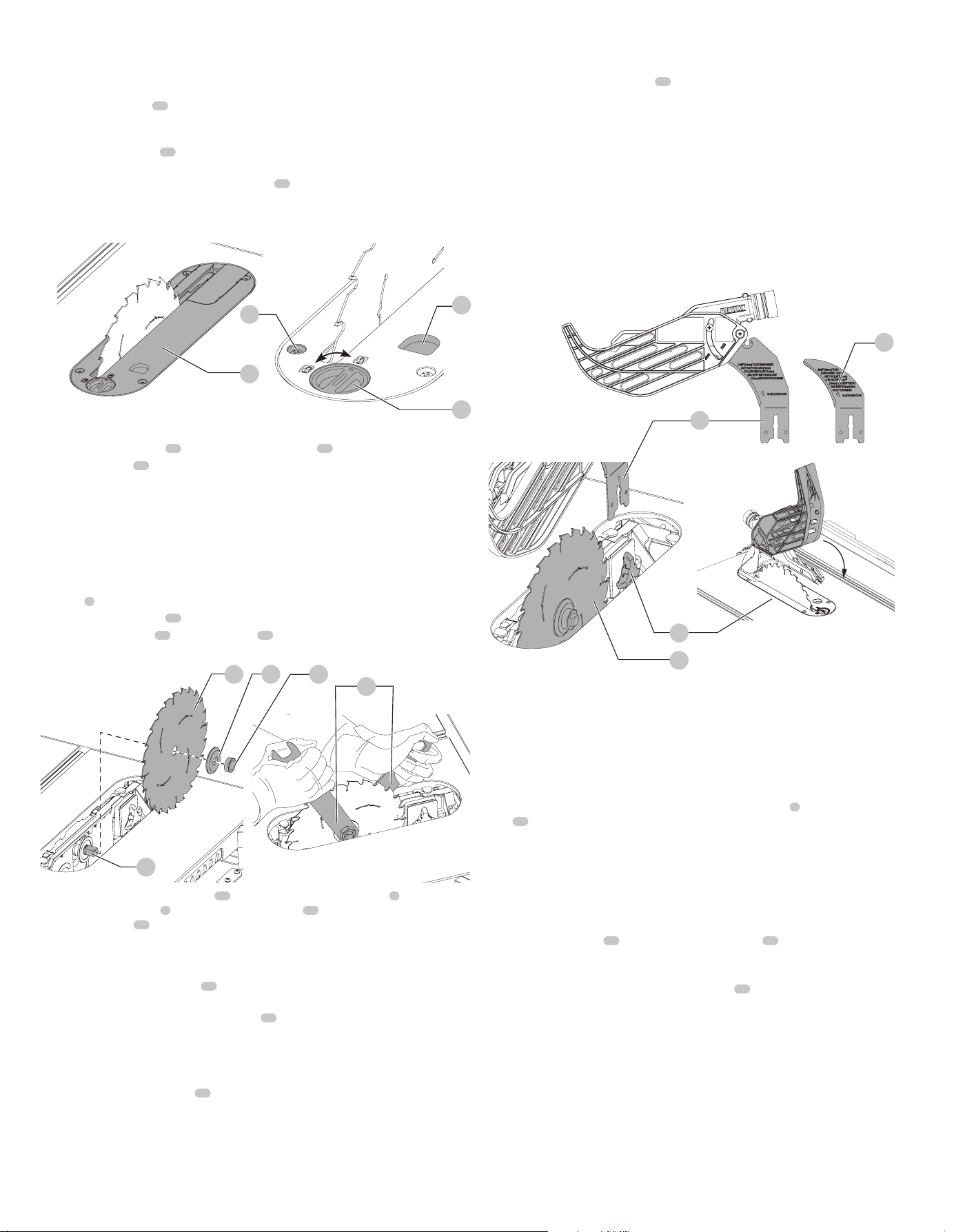
Installing the Throat Plate (Fig.C)
1. Align the throat plate
15
as shown in FigureC, and insert the tabs on the back of the throat
plate into the holes on the back of the tableopening.
2. Rotate cam counterclockwise until the front of throat plate drops into place. Secure by
rotating cam lock knob
24
clockwise 1/4 turn (when cam lock is under the table holding the
throat plate in place).
3. The throat plate includes four adjustment screws
25
which raise or lower the throat plate.
When properly adjusted, the front of the throat plate should be flush or slightly below the
surface of the top and secured in place. The rear of the throat plate should be flush or slightly
above the tabletop.
Fig. C
15
26
24
25
Removing the Throat Plate
1. Remove the throat plate
15
by turning the cam lock knob
24
1/4 turn counterclockwise
2. Using finger hole
26
on the plate, pull throat plate up and forward to expose the inside of
the saw. DO nOT operate the saw without the throatplate.
WARNING: To reduce the risk of serious personal injury, the throat plate must be locked in
place at alltimes.
Installing/Replacing the Blade (Fig.A,C, D)
CAUTION: Always wear gloves for handling saw blades and rough material. Saw blades
should be carried in a holder whereverpracticable.
1. Raise the saw blade arbor to its maximum height by turning the blade height adjustment
wheel
6
clockwise.
2. Remove the throat plate
15
.
3. Remove the arbor nut
27
and clamp washer
28
from the saw arbor by
turningcounterclockwise.
Fig. D
2 28 27
29
19
4. Place the saw blade on to the arbor
29
making sure the teeth of the blade
2
point down
at the front of the table
1
. Assemble the clamp washer
28
and arbor nut to the arbor and
tighten arbor nut
27
as far as possible by hand, making sure that the saw blade is against
the inner flange and the clamp washer is against the blade. Ensure the largest diameter of
the clamp washer is against the blade. Ensure the arbor and clamp washer are free from dust
anddebris.
5. Use the open end of the wrench
19
to keep the arbor from rotating when tightening the
arbornut.
6. Using the other wrench, tighten the arbor nut
27
by turning itclockwise.
nOTE: Different types of blades make different kerfs (width of cuts). Therefore, it is necessary
to check adjustment of rip scale when changing blades. Replacement blade MUST not
exceed the thickness stated on the riving knife. The riving knife provided with the saw is .063"
(1.6mm)thick.
7. Install and lock the throat plate
15
.
Installing/Removing the Blade Guard Assembly and Riving Knife
(Fig. E)
WARNING: Use blade guard assembly for all through-cutting.
nOTE: The saw is shipped with the non-through-cutting riving knifeinstalled.
1. Raise the saw blade arbor to its maximumheight.
2. Loosen the riving knife lock knob
30
(minimum of three turns).
3. To disengage riving knife lock pin, push lock knob toward the riving knife as indicated by the
yellow arrows on theknob.
4. While pushing the lock knob, lift the riving knife out of the clamp. Then slide the blade guard
assembly into the clamp until it bottomsout.
WARNING: Do not insert both blade guard assembly and riving knife into the clamp at the
sametime.
5. Release the lock knob to engage the lock pin. Give the blade guard a slight pull upwards to
ensure pin is engaged.
6. Tighten the riving knife lockknob.
7. Reinstall the throatplate.
8. To remove the bladed guard assembly, follow these steps in reverseorder.
nOTE: Follow the same steps above for riving knifeinstallation.
Fig. E
30
2
11
21
WARNING: Before connecting the table saw to the power source or operating the saw,
always inspect the blade guard assembly and riving knife for proper alignment and
clearance with saw blade. Check alignment after each change of bevel angle.
WARNING: Confirm that the blade remains covered when the guard is lifted and released
from its highest (or deepest) cutting depth, and whenbeveled.
nOTE: DO NOT operate saw if riving knife lock pin is not locked into the blade guard or
rivingknife.
When properly aligned, the riving knife will be in line with the blade at both table top level, and
at the top of the blade. Using a straight edge, ensure that the blade
2
is aligned with the riving
knife
21
. Operate the blade tilt and height adjustments through the extremes of travel and
ensure the blade guard assembly clears the blade in all operations and that the anti-kickback
assembly isfunctioning.
Assembling the Rip Fence (Fig.F)
The rip fence can be installed in two positions on the right [position 1 for 0" to 20" (508mm)
ripping, and position 2 for 4" (102mm) to 24.5" (622mm) ripping and one position on the left of
your tablesaw.
1. Align the locator pins
31
on the fence rails with the slots
32
on each fenceend.
2. Place fence onto the rail as shown in FigureF maintaining pin and slot alignment on both
ends of thefence.
3. Secure the rip fence by snapping down the latches
17
to the rails. Be sure to snap both front
and rear latches inplace.
Loading ...
Loading ...
Loading ...