Loading ...
Loading ...
Loading ...
1. Overview
0008
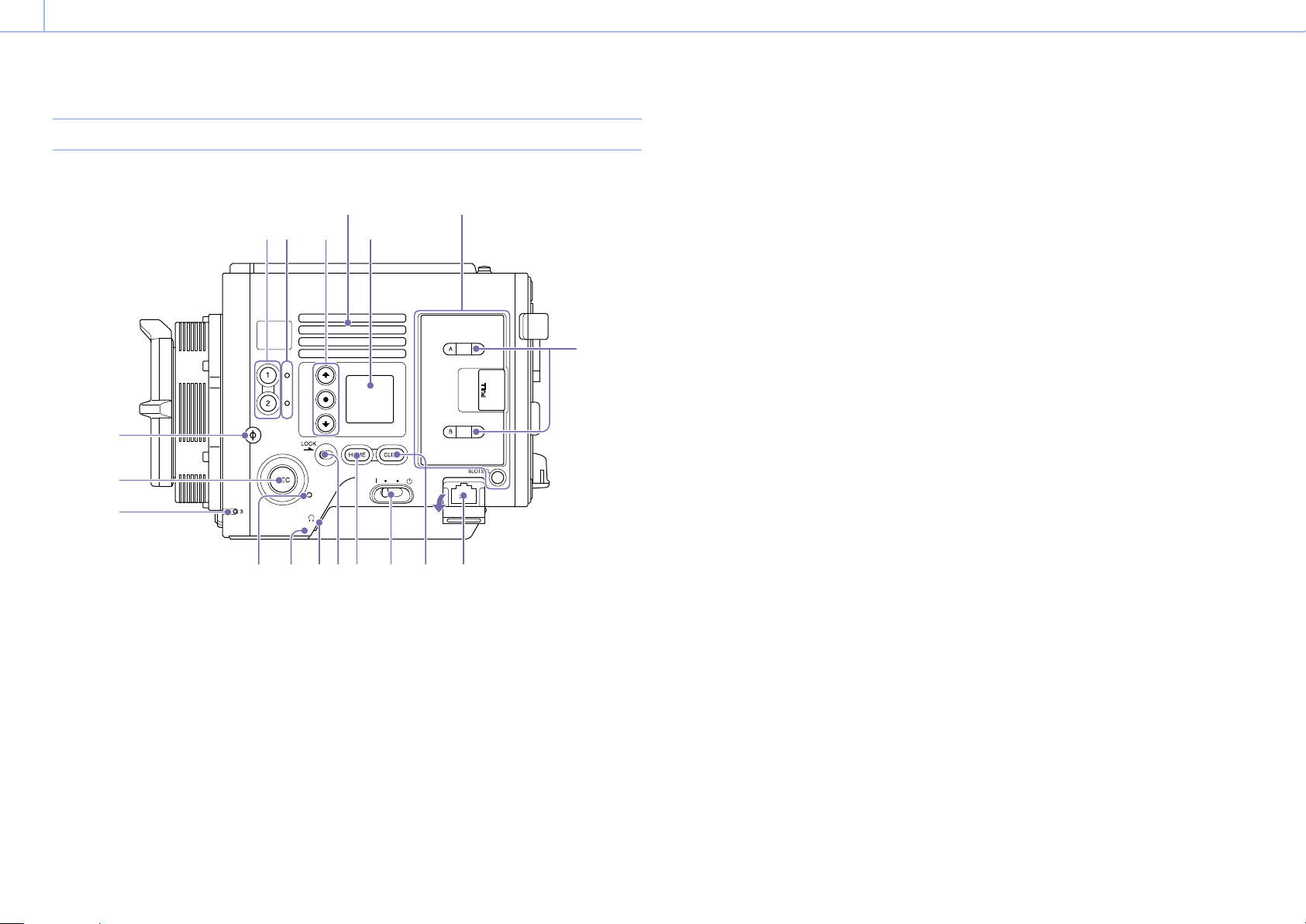
Location and Function of Parts
Operator Side
4
678910111213
15
16
14
1 2 3
5
Air inlet
SxS memory card
slot block (page 9)
1. ASSIGN (assignable) buttons 1/2 (page 39)
Assign functions using the EDIT page of the
user functions screen (page 39).
The assigned function toggles between on/off
(enable/disable) or is activated with each
press.
2. ASSIGN (assignable) lamps 1/2 (page 39)
Each lamp is lit orange when the assigned
function is on (enabled) or activated, and not
lit when the function is off (disabled).
3. Mini display ITEM keys 1 to 3
Controls the operation of functions on the
mini display (page 76).
4. Mini display
Displays various setup items, such as shutter
angle, that you can check or modify
(page 76).
5. ACCESS lamps (SLOT A/B)
Each lamp is lit when the recording media in
SxS card slot A/B is the target for recording/
playback and when data is being written to or
read from the recording media in SxS card slot
A/B (page 24).
6. Network connector (RJ-45)
Connect to a wired LAN network using a LAN
cable (not supplied) for remote control of the
unit (page 79).
7. CLIPS button
Press to display the clip screen on the mini
display to enable clip operations (page 78).
Simultaneously, the clip list screen is displayed
on the sub display and can also be used for
clip operations.
To switch from playback mode to shooting
mode, press the HOME button.
8. Power switch
Set to the ON position () to turn the power on.
Set to the OFF position () to turn the power
off.
[Notes]
This unit uses a small amount of standby power
even when the power switch is set to OFF. Remove
the battery pack if the unit will not be used for a
prolonged period.
When removing the battery pack or the DC IN
power, be sure to first set the power switch to the
OFF position. Interrupting the power supply during
recording or during memory card access could cause
a malfunction.
9. HOME button
Press to clear the item selection display and
return to the Home screen on the mini display.
If pressed when the unit is in playback state,
the unit transitions to shooting mode
(page 76).
10. LOCK switch
Locks the operation of the buttons on the
Operator side. When locked, the switch
background LED lights in orange.
11. Headphones connector (stereo mini jack)
Connect to earphones for audio monitoring.
You can monitor the input audio during
shooting/recording and playback sound
during playback (page 75).
12. Built-in speaker
You can monitor the input audio during
shooting/recording and playback sound
during playback. The speaker also sounds
alarms to reinforce visual warnings
(page 75).
If you connect earphones to the headphones
jack, the speaker output is suppressed
automatically.
13. REC ACTIVE lamp
The lamp is lit green when the REC button is
enabled.
14. ASSIGN (assignable) lamp 3 (page 39)
The lamp is lit orange when the assigned
function is on (enabled) or activated, and not
lit when the function is off (disabled).
15. REC (recording start/stop) button/lamp
Press to start recording, turning the REC lamp
on. Press again to stop recording, turning the
REC lamp off (page 83).
The REC lamp flashes when a device error or
warning occurs.
16. f mark
The f mark is on the same plane as the image
sensor.
To measure the precise distance between the
unit and the subject, use the
f
mark as a
reference.
Loading ...
Loading ...
Loading ...